
SECTION 7C - AUTOMATIC TRANSMISSION (AW30-40LE)
General Description
Construction
Electronic Control Components
Transmission Control Module (TCM)
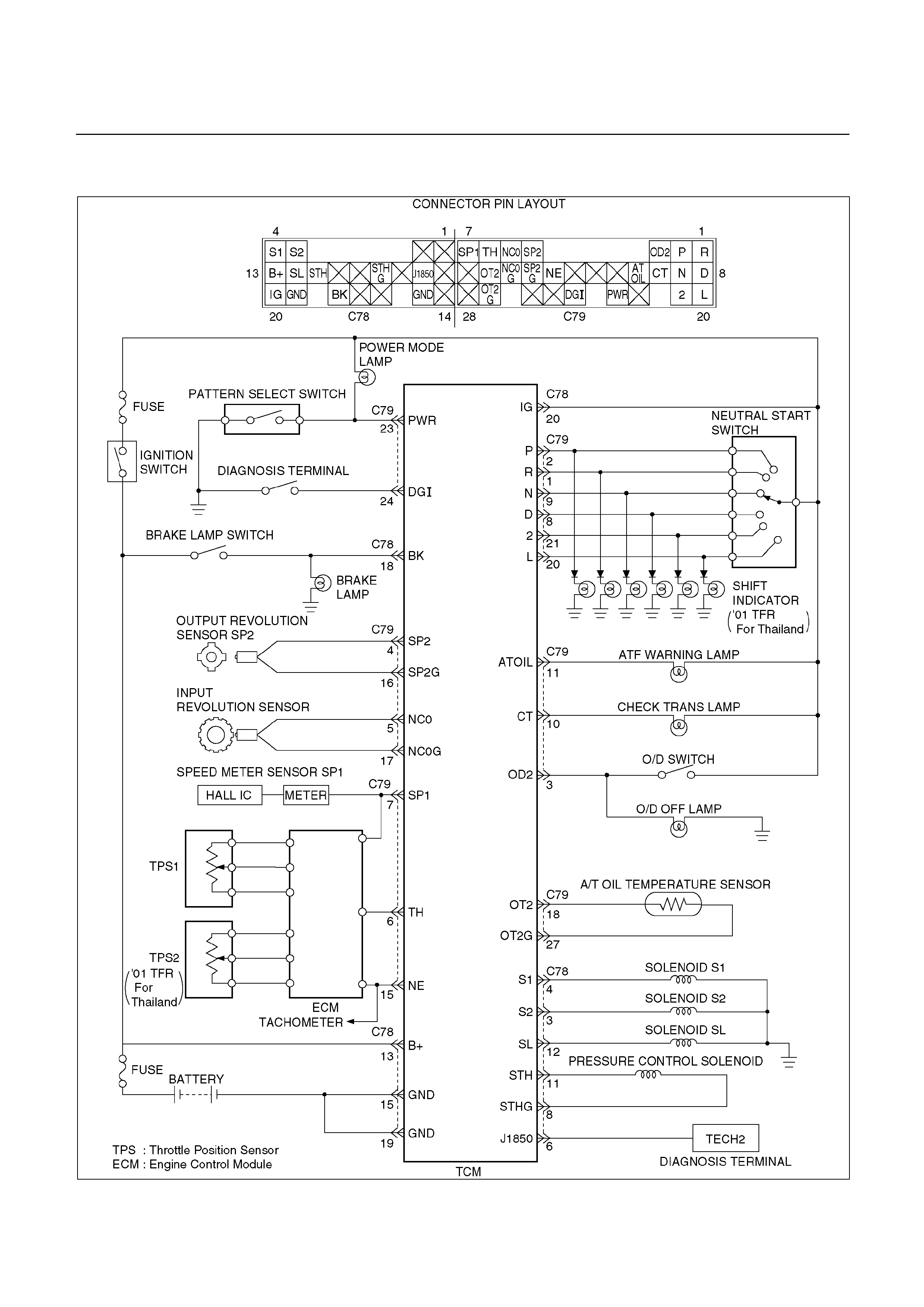
Control System Diagram
Control and Functions
Major Input/Output Components
Location of Clutch, Brake, One-way Clutch and Solenoid
Operation of Clutch, Brake and One-Way Clutch
Speed Change and Lock-up Pattern
Overdrive and Lock-up Operating Conditions
Diagnosis
Basic Troubleshooting
Self Diagnosis
Diagnosis with Tech 2
Using Tech 2 on the Vehicle
Connecting Tech 2 to the Vehicle
Transmission Data
TCC Data
Intermittent Conditions
Identification of Transmission Control Module (TCM)
Diagnostic Trouble Codes (DTC) Check
DTC P0120 (Flashing Code 21) Analog Throttle Signal Failure (VTH) (For UBS)
DTC P0502 (Flashing Code 24) Speed Meter Sensor Failure (SP1)
DTC P0705 (Flashing Code 17) Gear Selector Failure (PRND2L)
DTC P0710 (Flashing Code 16) Oil Temperature Sensor Failure (OT2)
DTC P0717 (Flashing Code 14) Input Revolution Sensor Failure (NC0)
DTC P0722 (Flashing Code 11) Output Revolution Sensor Failure (SP2)

DTC P0727 (Flashing Code 13) Engine Revolution Signal Failure (NE)
DTC P0743 (Flashing Code 33) Torque Converter Clutch Control Lock-up (ON/OFF)
Solenoid Failure (SL)
DTC P0748 (Flashing Code 35) Pressure Control Solenoid Failure (STH)
DTC P0753 (Flashing Code 31) Solenoid 1 Failure (S1)
DTC P0758 (Flashing Code 32) Solenoid 2 Failure (S2)
DTC P1120 (Flashing Code 22) PWM Throttle Signal Failure (TH) (For TFR/S)
DTC P1121 (Flashing Code 23) Analog Throttle Signal Failure (VREF, VGND)
(ForUBS)
Wiring Diagram
Connector List
Troubleshooting Chart
Manual Shifting Test
Stall Test
Time Lag Test
Hydraulic Test
Road Test
Shift Point Chart and Lock-Up Point Chart
TCM Voltage Check
On-Vehicle Service
Transmission Fluid Level and Condition
ATF Replacement
Neutral Start Switch Inspection
Brake Signal Inspection
Vehicle Speed Sensor Inspection
Input and Output Revolution Sensor Inspection
Pattern Select Switch Inspection
Overdrive Switch Inspection
Solenoid Inspection
ATF Temperature Sensor Inspection
Throttle Position Sensor Inspection (UBS and TFR/S)
Throttle Position Sensor Inspection (’01 TFR)
Selector Lever
Transmission Control Module (TCM)
Shift Solenoid and Lock-Up Solenoid

Valve Body Assembly and Pressure Control Solenoid
Rear Oil Seal (Adapter Housing, 44)
Rear Oil Seal (Extension Housing, 42)
Transmission Removal and Installation (UBS)
Transmission Removal and Installation (TFR/S)
Unit Repair
Major Components
Disassembly of Major Components (1)
Reassembly of Major Components (1)
Disassembly of Major Components (2)
Reassembly of Major Components (2)
Disassembly of Major Components (3)
Reassembly of Major Components (3)
Disassembly, Inspection and Reassembly of Minor Components
Oil Pump
OD Planetary Gear and OD Direct Clutch Assembly (C-0)
OD Support Assembly
Direct Clutch Assembly (C-2)
Forward Clutch Assembly (C-1)
Front Planetary Gear
Planetary Sun Gear and No.1 One-Way Clutch
Second Brake Assembly (B-2)
Rear Planetary Gear Assembly and Output Shaft
First and Reverse Brake Assembly (B-3)
Transmission Valve Body Assembly
Lower Valve Body
Upper Valve Body
Transmission Case
Torque Converter
Adapter Housing (44)
Extension Housing (42)
Main Data and Specifications
General Specifications
Torque Specifications
Special Tool

CAUTION:
When fasteners are removed, always reinstall them
at a the same location from which they were
removed. If a fastener needs to be replaced, use
the correct part number fastener for that
application. If the correct part number fastener is
not available, a fastener of equal size and strength
(or stronger) may be used.
Fasteners that are not reused, and those requiring
thread locking compound, will be called out. The
correct torque values must be used when installing
fasteners that require torque. If the above
conditions are not followed, parts or system
damage could result.
GENERAL DESCRIPTION
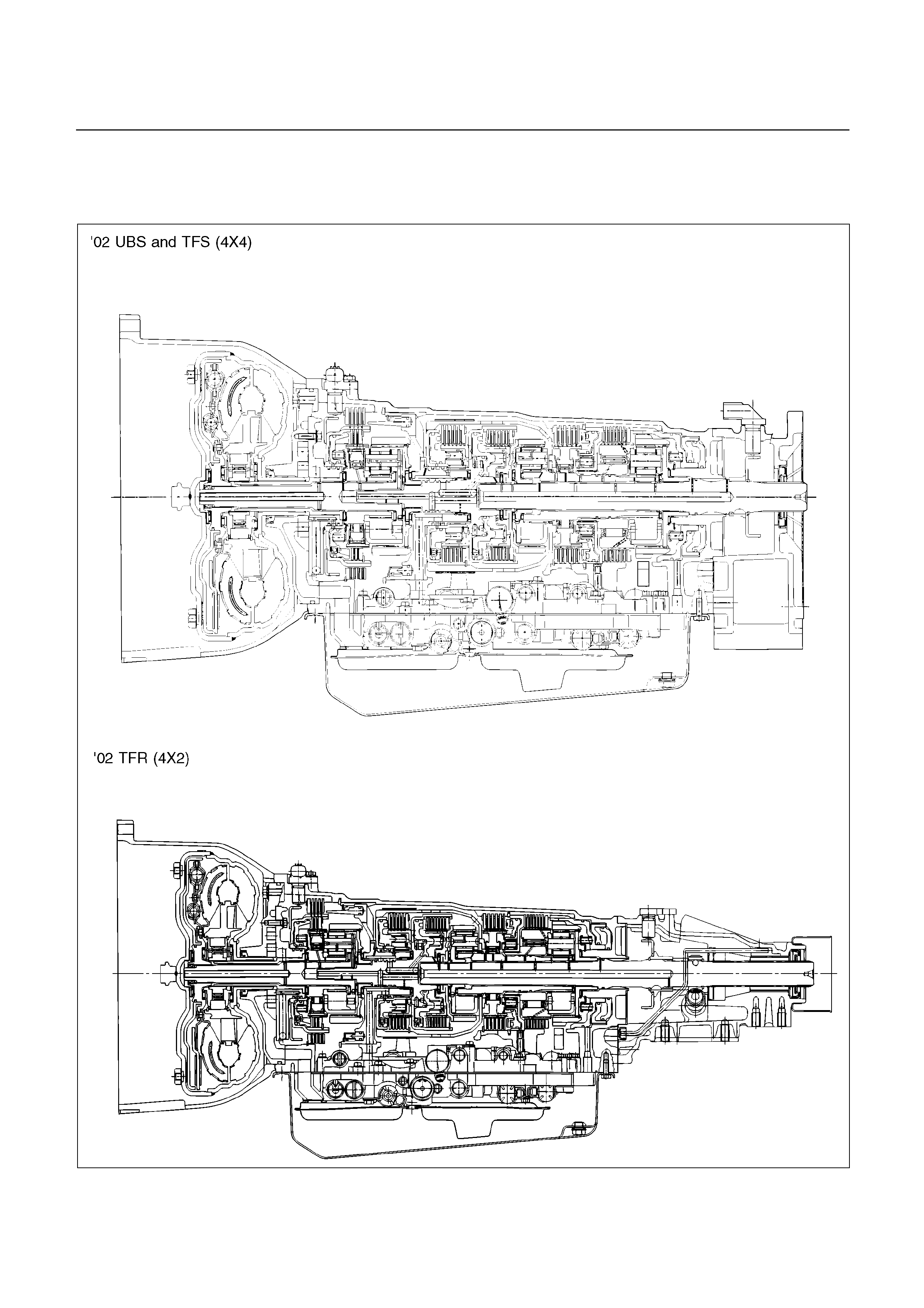
CONSTRUCTION
A07RY00001&A07L200001
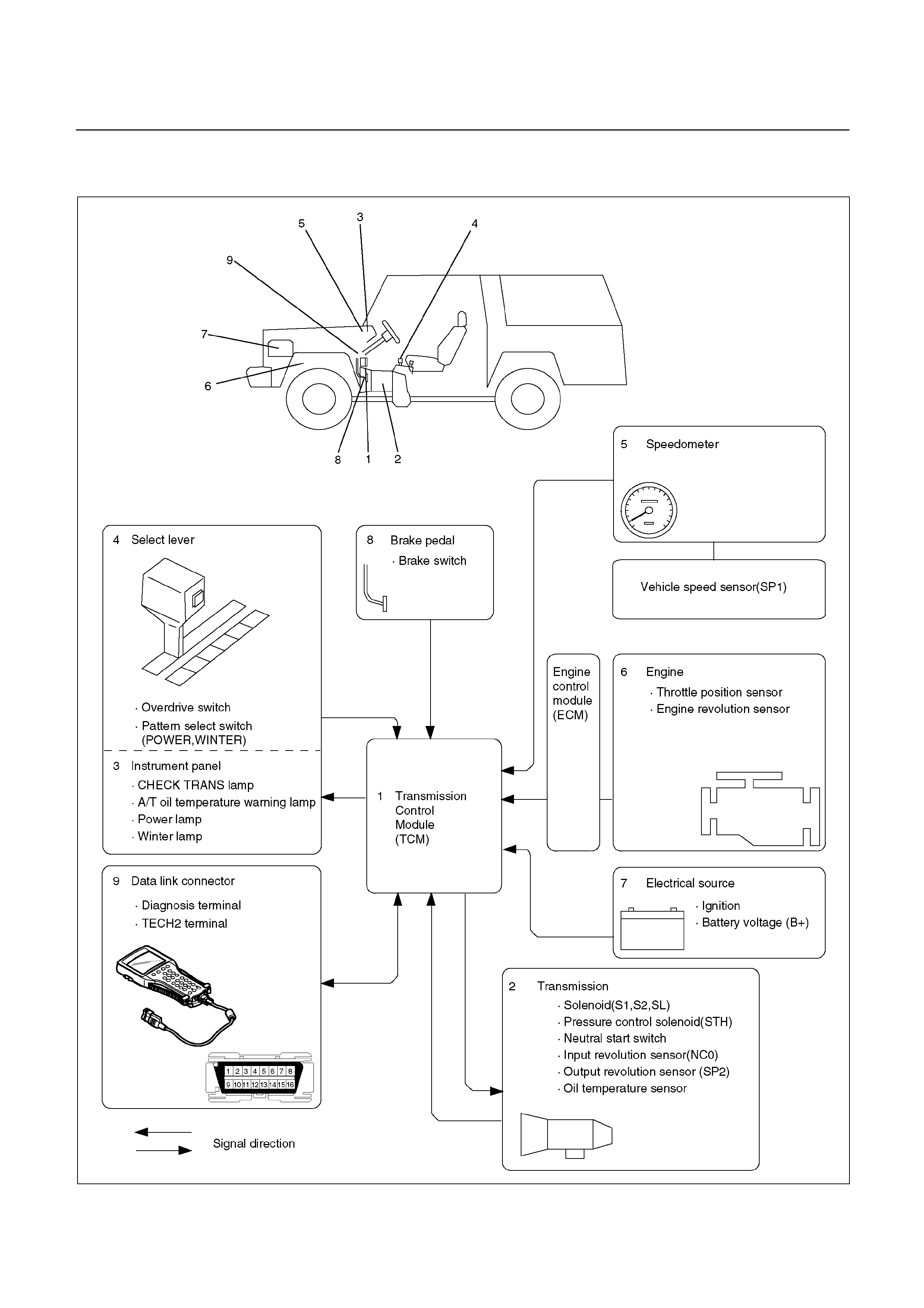
ELECTRONIC CONTROL COMPONENTS - UBS JACKAROO
C07R200019
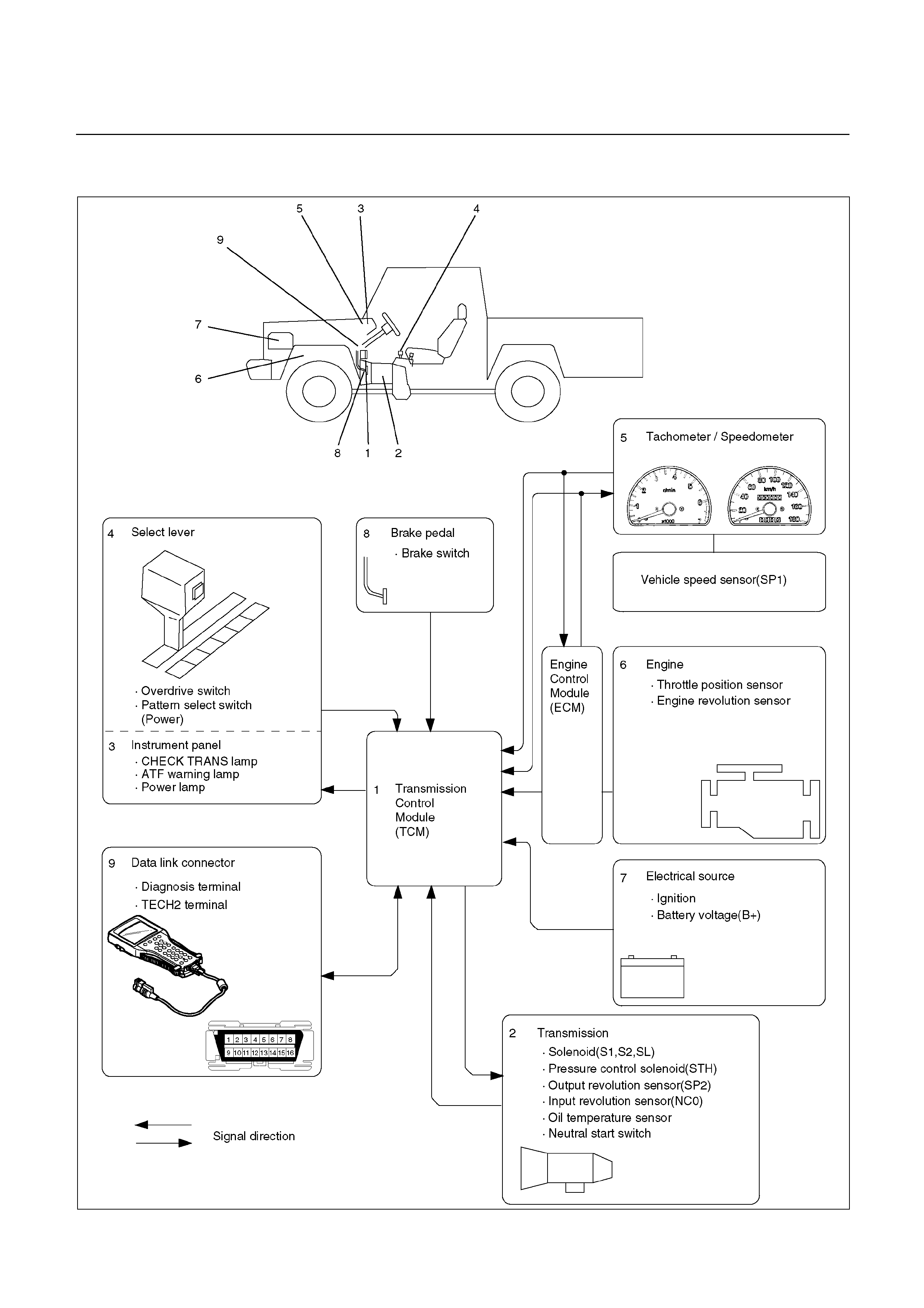
ELECTRONIC CONTROL COMPONENTS - TFR/S RODEO
C07L200001
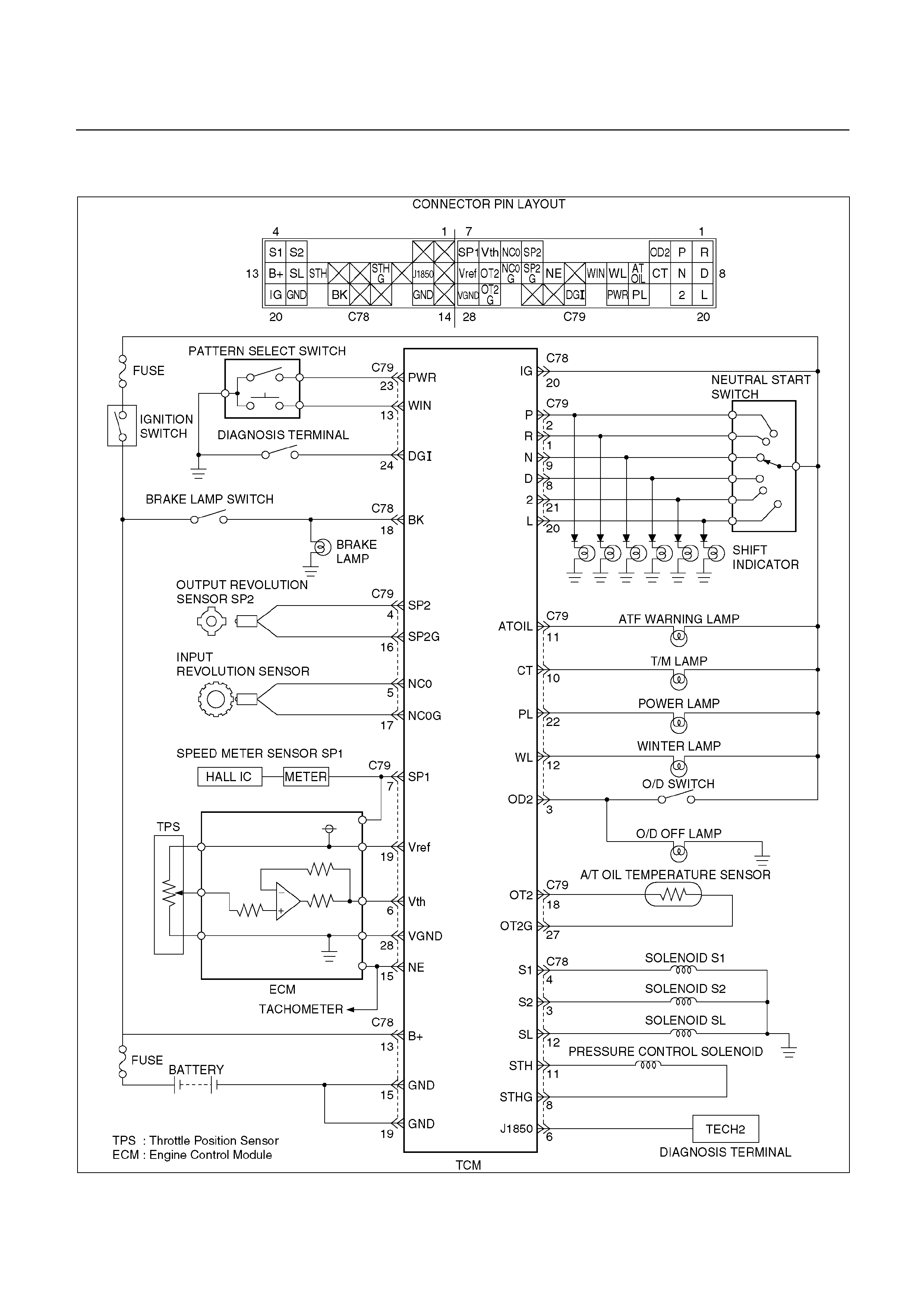
TRANSMISSION CONTROL MODULE (TCM) - UBS JACKAROO
C07R200020
TRANSMISSION CONTROL MODULE (TCM) - TFR/S RODEO
C07L200002
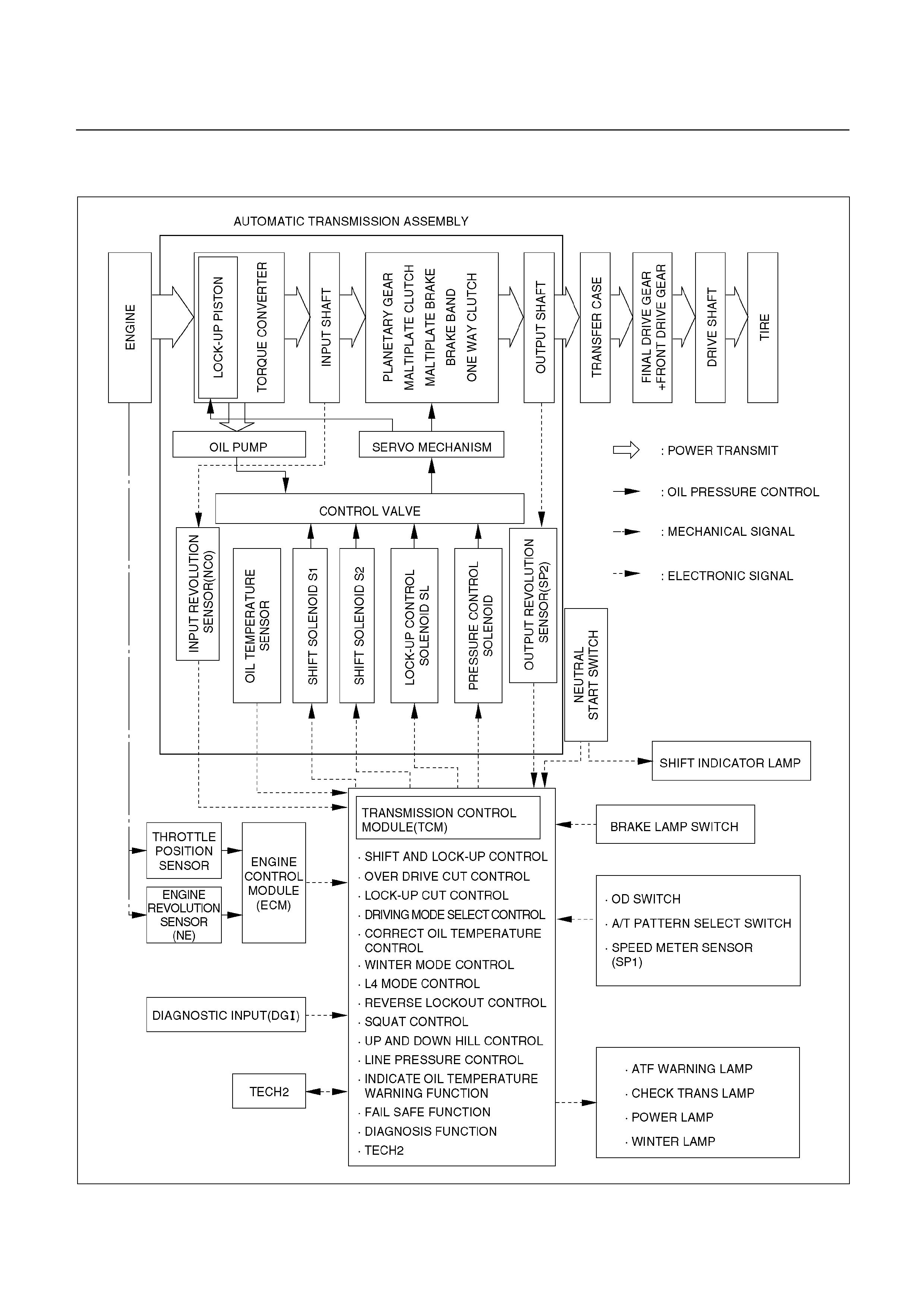
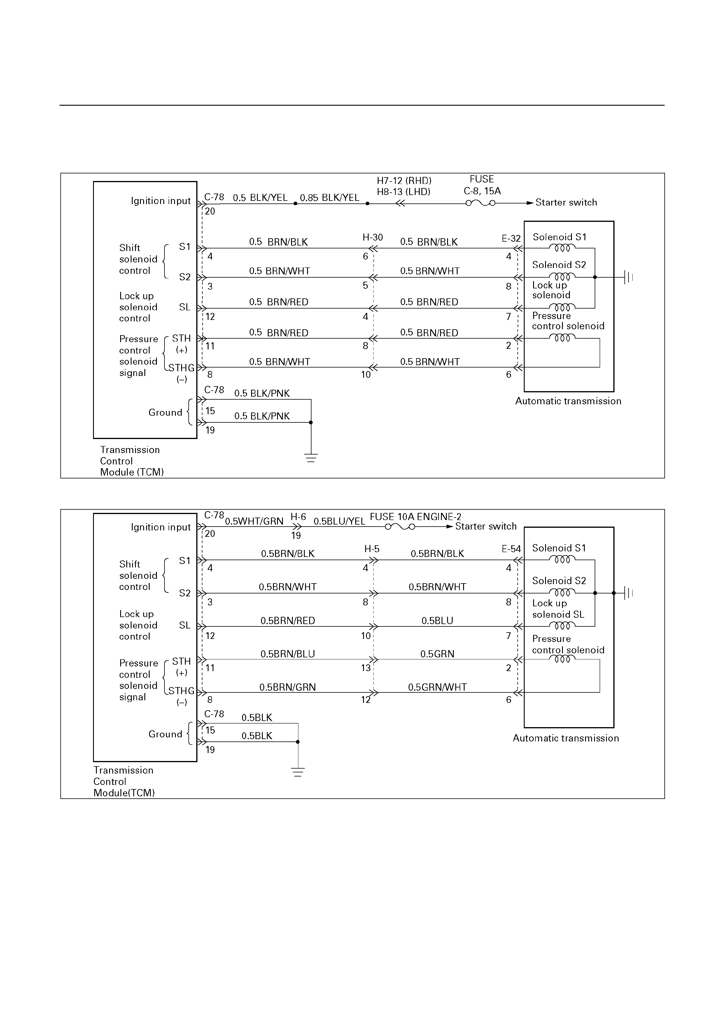
CONTROL SYSTEM DIAGRAM - UBS JACKAROO
C07R200021

CONTROL SYSTEM DIAGRAM - TFR/S RODEO
C07L200003

CONTROL AND FUNCTIONS
Item Description
Shift and lock-up control • In D range, speed change point and Lock-up point can be
changed by setting pattern selection switch to "POWER",
"NORMAL" or "WINTER (UBS)" mode.
• Gear shift position in the conditions made up of transmission shift
positions (D.2.L) combined with pattern selection switch
(POWER, NORMAL, and WINTER) can be controlled in
accordance with vehicle speed and the opening of throttle valve.
Overdrive cut control • If O/D switch is set on in D range (O/D OFF lamp ON), gear shift
to O/ D is not effected.
• Overdrive is released at O/D switch on and high transmission oil
temperature (More than 130°C).
However, to prevent engine over revolution
• 4
→3 shifting at vehicle speed is less than 118 km/h (UBS) or
117 km/h (TF).
• 3
→4 shifting at vehicle speed is more than 131 km/h (UBS) or
125 km/h (TF).
Lock-up cut control • In D range, 2nd (TF), 3rd or O/D lock-up is conducted in
"POWER" or "NORMAL" mode.
• In 2, L range, lock-up is off in the whole area.
• Lock-up timing is controlled to reduce gear shift shock using kind
of gear shift (shift up, etc.) lock-up status at the time of gear shift
judgement, gear step and throttle opening after gear shift.
• Lock-up is released at brake on or high transmission oil
temperature
(More than 130°C UBS) .
(More than 140°C TF).
• Lock-up is prohibited when idling is defected by throttle position
sensor.
Driving mode select control • The TCM selects a suitable driving mode from the nine kinds for
the variety driving condition.
i) Economy mode ii)Power mode iii)Winter mode(UBS) iv)HOT1
mode v)HOT2 mode vi)L4 mode(4×4) vii)Slope mode(UBS)
(Up slope 1, Up slope 2 and Down slope mode)
• The priority of driving mode:
Economy < Power < Slope(UBS) < L4(4×4) < Winter(UBS) <
HOT1 < HOT2
Squat control • When the TCM detects D signal on, the TCM controls 1–3–1 shift
by setting a timer, in order to improve the shift feel at N→D.
Line pressure control • The TCM output current which corresponds to throttle oil pressure
to pressure control solenoid based on throttle opening.
Indicate oil temperature warning function • If the transmission oil temperature sensor senses that
transmission oil temperature is greater than 146°C, the TCM turn
on A/T OIL TEMP warning lamp. (The warning lamp is turned off,
if oil temperature is less than 126°C.)

Item Description
L4 mode control (4×4) • The TCM judges whether the transfer is engaged in high or low
based on the ratio rpm data from output speed sensor in the
transmission and the rpm data from speed meter sensor to select
the shift map.
Up and down hill control (UBS) • The TCM judges up and down hill, and change shift pattern based
on throttle opening and acceleration.
Correct oil temperature control • If the temperature exceeds a predetermined value, the TCM
selects the high oil temperature shift point for downshifting, thus
preventing the oil temperature from rising. (More than 130°C, D
range)
Winter mode control (UBS) • The TCM controls the vehicle start smoothly on low frictional road
(eg. snow or ice) by executing this control.
Activate condition:
1. Excluding "2", "L" range
2. Vehicle speed is less than 11 km/h
3. Transmission oil temperature is less than 115°C
4. Throttle opening is less than 8%
5. Excluding winter mode
Cancel condition:
1. When winter mode switch is pushed again
2. When either "2" or "L" is detected
3. Ignition switch "OFF"
4. Vehicle speed is more than 34 km/h for 1 second or mode
continuously
5. Transmission oil temperature is more than 130°C
Fail-safe function • When trouble occurs to vehicle sensor and each solenoid, TCM
automatically exerts fail-safe control not to spoil driveability.
• This control is exerted when sensor or actuator is in trouble, while
TCM works normally.
Diagnosis function • If there is an abnormality in vehicle sensors, each solenoid (S1-
S3, STH), or throttle position sensor, "CHECK TRANS" lamp is
actuated to warn the drive. But when the abnormality items have
been restored to normal, the light does not blink.
• Faulty parts are memorized in TCM. If self-diagnosis start signal
is inputted, "CHECK TRANS" lamp is blinked and results of
diagnosis are indicated. A history of faults remains recorded even
when IGN switch is off.
TECH 2 • Output of control data in the TCM
• Actuator (Solenoid) operation check
• Erasure of trouble code

MAJOR INPUT/OUTPUT COMPONENTS
Component Function
Vehicle speed sensor (Speedometer) Detects the vehicle speed (Back-up sensor of output revolution
sensor).
Output revolution sensor (Transmission) Detects the vehicle speed
Input revolution sensor (Transmission) Detects the input revolution (O/D direct clutch drum revolution).
Engine revolution sensor Detects the engine revolution.
Throttle position sensor Detects the throttle opening rate.
Neutral start switch Detects the select lever position.
Pattern select switch Detects whether the driver has selected "NORMAL",
"POWER", or "WINTER" (UBS) mode.
Overdrive switch Detects whether the driver has selected O/D.
Brake lamp switch Detects whether the driver has pressed the brake pedal or not.
Oil temperature sensor Detects the oil temperature.
Input
Diagnostic start switch Starts self-diagnosis and displays a code for faulty part if any.
Input/
Output
Data link connector When connected with Tech2 or tester, can communicate the
data for function check, etc.
Shift solenoid S1, S2 Selects shift point and gear position suited to the vehicle
running condition on the basis of TCM output.
Lock-up control solenoid SL Control the lock-up clutch suited to the vehicle running
condition on the basis of TCM output.
Pressure control solenoid STH Adjusts throttle pressure by energizing current of linear
pressure control solenoid to prevent the shift shock and to
obtain shift smoothly.
"CHECK TRANS" lamp When trouble has occurred to throttle position sensor, vehicle
speed sensor, or solenoid, "CHECK TRANS" lamp is blinked to
warn the driver. If also displays the trouble code.
A/T OIL TEMP warning lamp Lights when ATF oil temperature rises. (Turned on at greater
than 146°C. Turned off at less than 126°C.
Power mode lamp Informs the driver whether the vehicle is in power mode or not.
Output
Winter mode lamp (UBS) Informs the driver whether the vehicle is in winter mode or not.
Computer
Transmission Control Module (TCM) Based on the signal from each switch and sensors, judges
necessary shift point and lock-up operation, and send signal to
each solenoid.
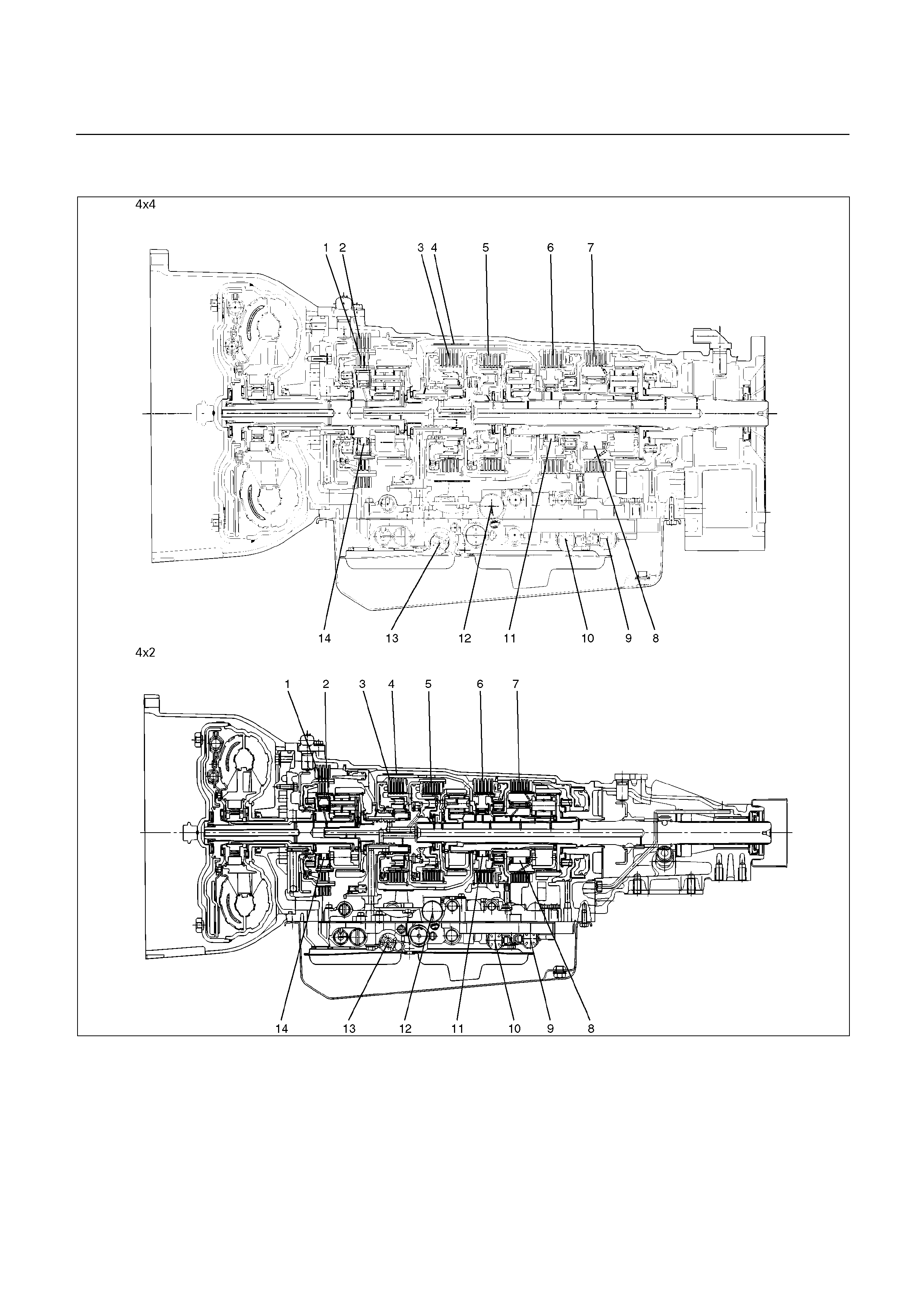
LOCATION OF CLUTCH, BRAKE, ONE-WAY CLUTCH AND SOLENOID
C07R200022
Legend
1. Overdrive direct clutch (C-0)
2. Overdrive brake (B-0)
3. Direct clutch (C-2)
4. Second coast brake (B-1)
5. Forward clutch (C-1)
6. Second brake (B-2)
7. First and reverse brake (B-3)
8. One-way clutch (No.2) (F-2)
9. Shift solenoid (S-1)
10. Shift solenoid (S-2)
11. One-way clutch (No.1) (F-1)
12. Pressure control solenoid (STH)
13. Lock-up solenoid (SL)
14. Overdrive one-way clutch (F-0)
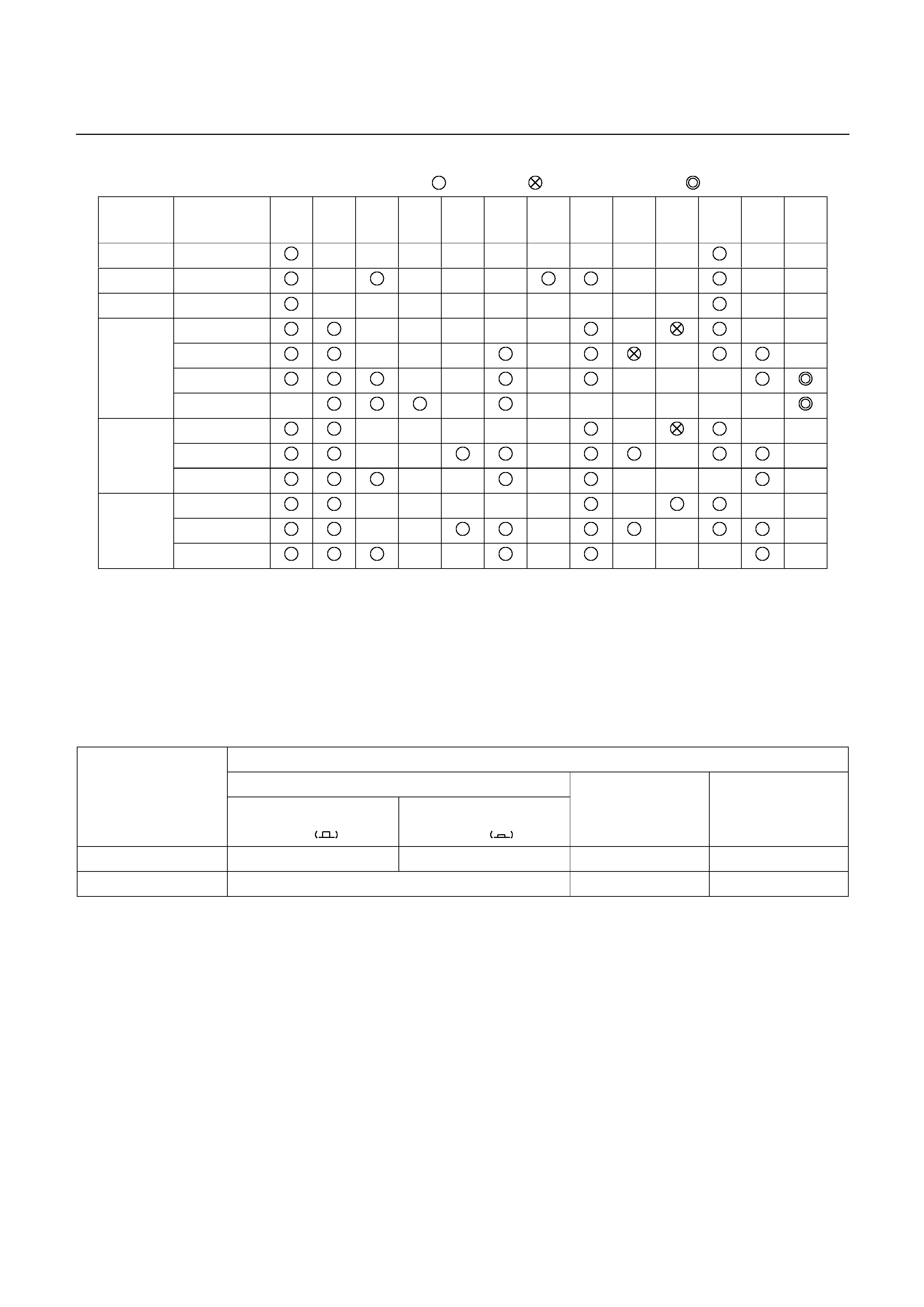
OPERATION OF CLUTCH, BRAKE AND ONE-WAY CLUTCH
: Operating : Free at coast down : Operating at lock-up
Shift lever
position Gear position C-0 C-1 C-2 B-0 B-1 B-2 B-3 F-0 F-1 F-2 S-1 S-2 S-3
P Parking
R Reverse
N Neutral
1st
2nd
3rd
D
O/D
1st
2nd
2
3rd
1st
(1*) 2nd
L
(2*) 3rd
(1*) Down-shift only in the L range and 2nd gear – no up-shift
(2*) Down-shift only in the L range and 3rd gear – no up-shift
SPEED CHANGE AND LOCK-UP PATTERN
If you select a speed range and a lock-up pattern as shown below by specifying respective positions of transmission
shift lever, transfer shift lever and pattern select switch, the transmission control computer controls speed change
and lock-up operations based on the specified pattern in accordance with the degree of throttle opening and vehicle
speed.
Transmission shift position
D
Pattern select sw.
position Overdrive switch
ON
Overdrive switch
OFF
2 L
NORMAL, POWER 1st [2nd]* [3rd] [O/D] 1st [2nd]* [3rd] [O/D] 1st 2nd (3rd) 1st (2nd) (3rd)
WINTER (UBS) 3rd fixing
[ ]: The lock-up operation is available.
( ): Transmission is shifted at high speed to prevent overrun.
*: TF model

OVERDRIVE AND LOCK-UP OPERATING CONDITIONS
The overdrive and lock-up clutch operate if the following conditions are satisfied.
Overdrive Lock-up clutch
Transmission shift position D range (1*)
O/D switch position ON (O/D OFF lamp OFF)
Brake lamp switch OFF
Throttle opening Except fully closed
Vehicle speed
(UBS)
About 49 km/h or more
(TFR/S)
About 34 km/h or more
(UBS)
3rd: About 50 km/h or more
O/D: About 65 km/h or more
(TFR/S)
2nd: About 35 km/h or more
3rd: About 49 km/h or more
O/D: About 59 km/h or more
(1*): If transmission oil temperature is more than 130°C (UBS and or 140°C (TFR/S), lock-up is
inhibit.
DIAGNOSIS
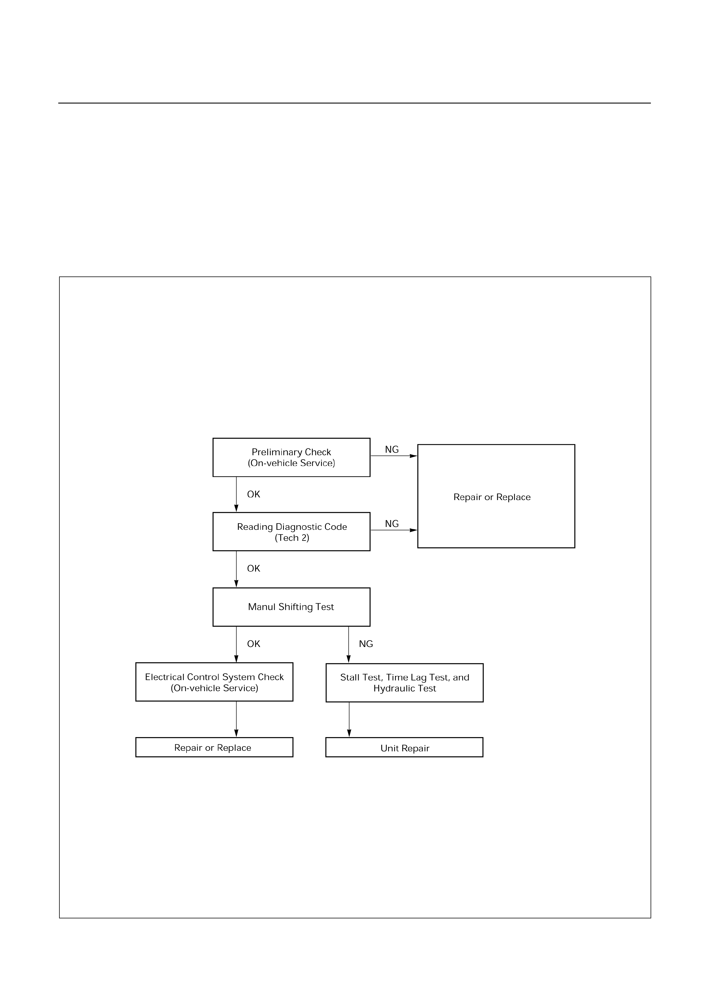
BASIC TROUBLESHOOTING
AW30-40LE transmission, called Electronic Controlled Transmission (ECT), differs from oil pressure control type
transmissions in that it is controlled by a microcomputer. Accordingly, its troubleshooting procedure differs also.
Before troubleshooting an ECT, first determine whether the problem is electrical or mechanical. To do this, just refer
to the basic troubleshooting flowchart provided below.
If the cause is already known, using the basic troubleshooting chart below along with the troubleshooting chart
should speed the procedure.
F07R200005
UBS
825R200084
TFR/S
825R200085
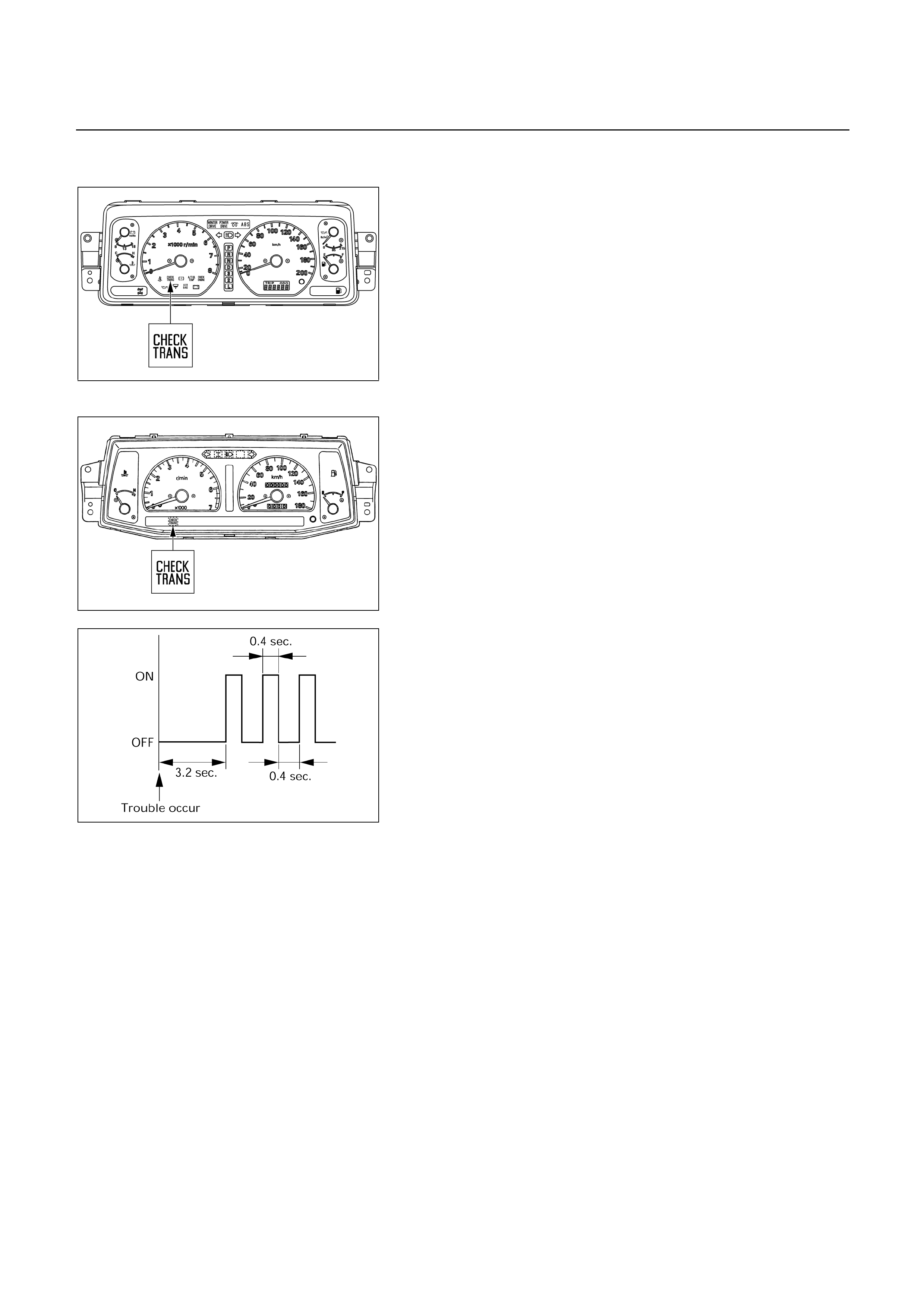
SELF DIAGNOSIS
Warning to the driver
When trouble has occurred to throttle position sensor,
vehicle speed sensor, or solenoid, “CHECK TRANS” lamp
is blinked (1.25 Hz) even during driving to warn the driver.
The trouble is recorded by trouble code is TCM.
When temporary trouble has been shooted, the “CHECK
TRANS” lamp stops blinking. This blinking can be stopped
by setting the ignition key off. But the trouble code remains
memorized in TCM.
F07LV002
UBS
TFR/S
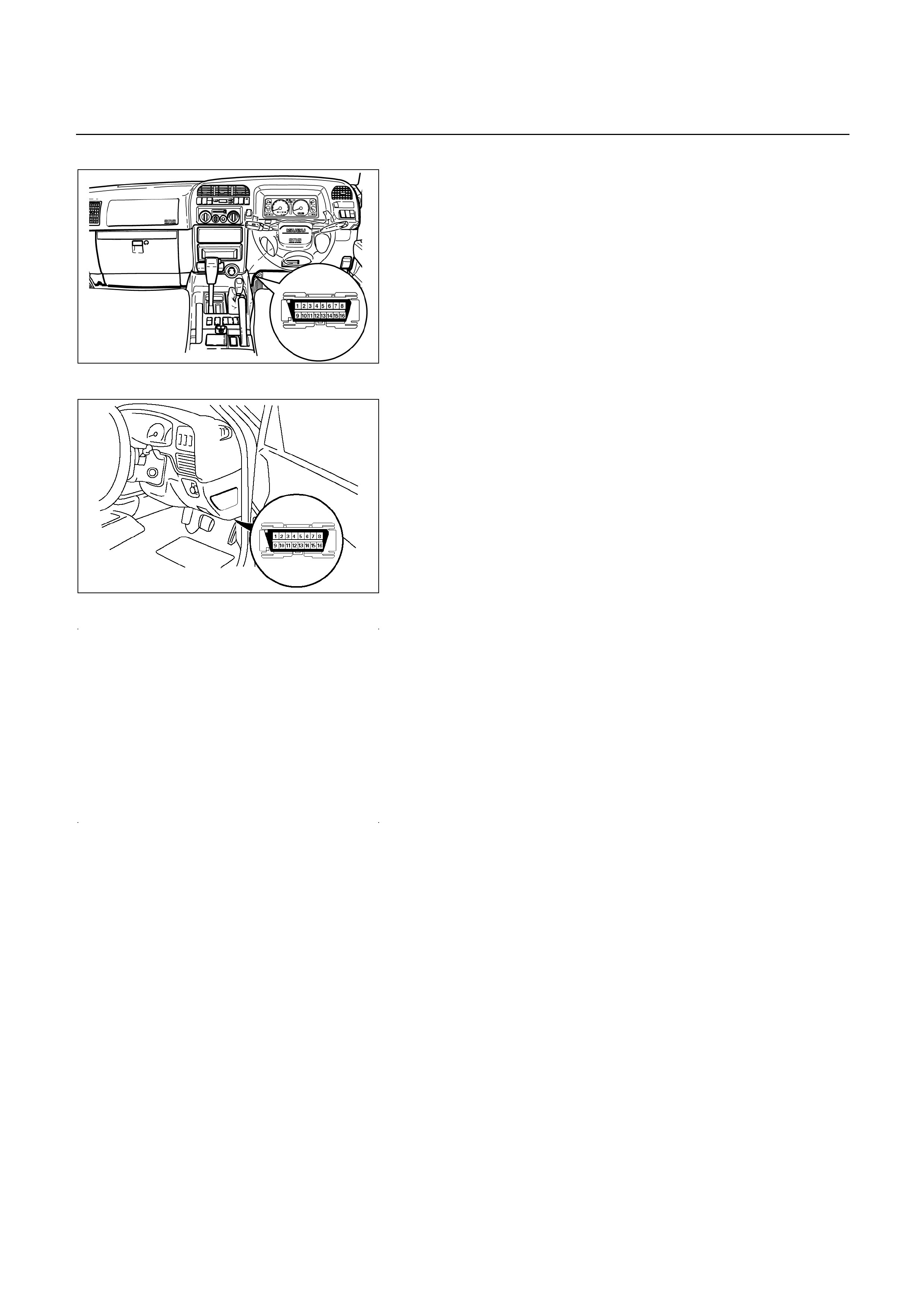
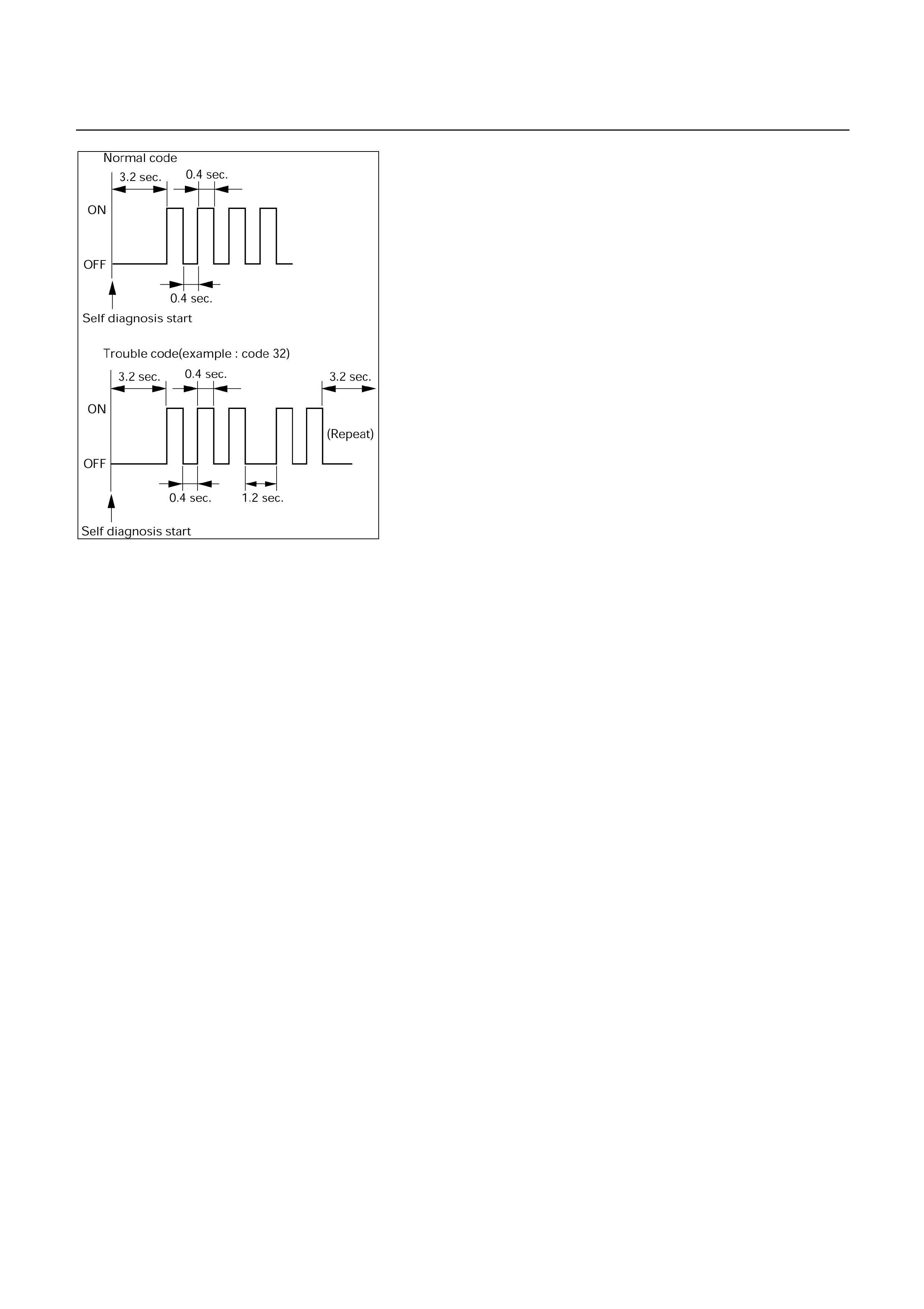
Self-diagnosis code display
For quick search for faulty parts, 11 (TF) or 12 (UBS)
different items of trouble code are indicated by “CHECK
TRANS” lamp blinking.
The storaged trouble codes can be identified by shorting
the terminals No.11 and No.4 or 5 (ground) of diagnosis
connector with a lead wire.
F07LV001
Indication Method:
(1) Terminals No.11 and No.4 or 5 (ground) of diagnosis
connector are short circuited.
(2) Turn the ignition key to the ON position.
(3) In case there no trouble, normal code is indicated.
(4) In case a plurality of trouble codes have occurred at a
time, each code is indicated three times in numerical
order.
NOTE:
Power line runs through diagnosis connector.
Be careful shorting with a lead wire, etc.
(The vehicle side of control module may be damaged.)
For identification of trouble code, connect Tech 2 to
diagnosis connector.
Clear of trouble code memory
1. Clear the trouble code memory using F1: Clear DTC
Information for Tech 2.
2. After more than 1 second has elapsed after the ignition
key has been turned ON, short between NO.11 and No.4
or 5 (ground) of data link connector. Then, after 1 second,
but within 6 seconds, discontinue shorting.

Flashing code
Trouble Code
(P-Code) Mode Diagnostic area and Failure
11
(P0722)
Output revolution sensor failure (SP2)
13
(P0727)
Engine revolution signal failure (NE)
14
(P0717)
Input revolution sensor failure (NC0)
16
(P0710)
Oil temperature sensor failure (OT2)
17
(P0705)
Gear selector failure (PRND2L)
21
(P0120)
Analog throttle signal failure (VTH)
(For UBS)
22
(P1120)
PWM throttle signal failure (TH)
(For TFR/S)
23
(P1121)
Analog throttle signal failure (VREF, VGND)
(For UBS)
24
(P0502)
Speed meter sensor failure (SP1)
31
(P0753)
Solenoid 1 failure (S1)
32
(P0758)
Solenoid 2 failure (S2)
33
(P0743)
Torque converter clutch control lock-up
(ON/OFF) solenoid failure (SL)
35
(P0748)
Pressure control solenoid failure (STH)
F07R200014

DIAGNOSIS WITH TECH 2
In this AW30-40LE transmission, troubleshooting can be
performed for electrical faults using the Tech 2 scan tool.
If the CHECK TRANS lamp blinks, or if an electrical fault in the
transmission may probably exist, check trouble codes using
the Tech 2 scan tool.
In the diagnostic procedures described in this manual, first
repair the faulty positions indicated by trouble code in the orde
r
of numbers and then perform troubleshooting for the fault
y
positions that are not indicated by trouble code. For correct
troubleshooting, it is necessary to first repair the trouble codes
of lower-order numbers, then to repair the trouble codes o
f
higher-order numbers in sequence.
How to Use This Manual:
Check trouble codes using the Tech 2 scan tool.
If no codes are set:
Refer to Data List and identify the electrical faults that are
not indicated by trouble code.
If codes are set:
Record all the codes displayed by the Tech 2 and check i
f
the codes are intermittent (intermittent faults).
Clear the codes.
Drive the vehicle for a test to reproduce the faulty status.
Check trouble codes again using the Tech 2.
If no code is displayed by test driving, the fault is
intermittent. In this case, refer to the cautions on
intermittent conditions.
If a code is present, refer to “DIAGNOSTIC TROUBLE
CODES (DTC) CHECK” for diagnosis.
Because a code of high-order number may be set for the
reason that a code of low-order number has been set afte
r
occurrence of a fault, perform repair work starting with a
lower-order number is ascending order.
USING TECH 2 ON THE VEHICLE
NOTE: Due to the constant evolution of TECH 2
software, the screens shown in this section may
differ slightly from those displayed for the vehicle
being tested.
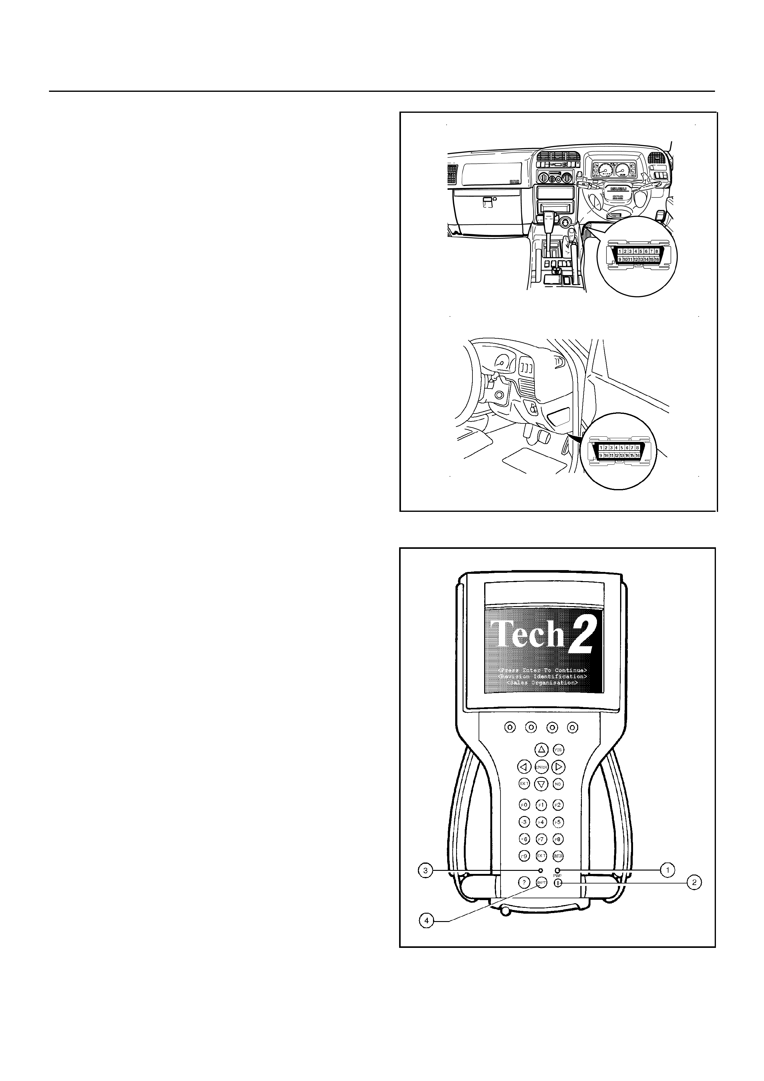
Connecting TECH 2 To The Vehicle
1. Connect Tech 2 to the vehicle DLC, with the DLC
cable and the 16/19 pin adapter.
2. Switch the unit on by pressing the power button (2).
A green light (1) should come on indicating that the
tool is receiving power.
NOTE: At this time the technician should see the Power
On Self Test (POST) run. The POST is a built in
diagnostic self test for the TECH 2 that should find most
common system faults. The POST is run on every
power up to ensure the best operation of the tool. After
the completion of the POST, the TECH 2 unit will briefly
show the POST results. If POST passes, the tool will
continue onto the title screen. If POST fails, results of all
tests will be displayed, and this should show which test
failed. POST failures may be classified as fatal or non-
fatal. A fatal error will not allow the user to continue
using the tool. Failure of the keypad would be an
example of a fatal error. Non-fatal errors found during
the POST will allow continued use of the TECH 2, but
with some limitations. If either a fatal or non-fatal error
occurs, refer to the Troubleshooting section of the
TECH 2 User's Guide.
1. Power Status Indicator Light
2. PWR (Power) Key
3. SHIFT Key Status Indicator Light
4. SHIFT Key
3. At the Tech 2 title screen press the ENTER key to
continue.
UBS
TFR/S
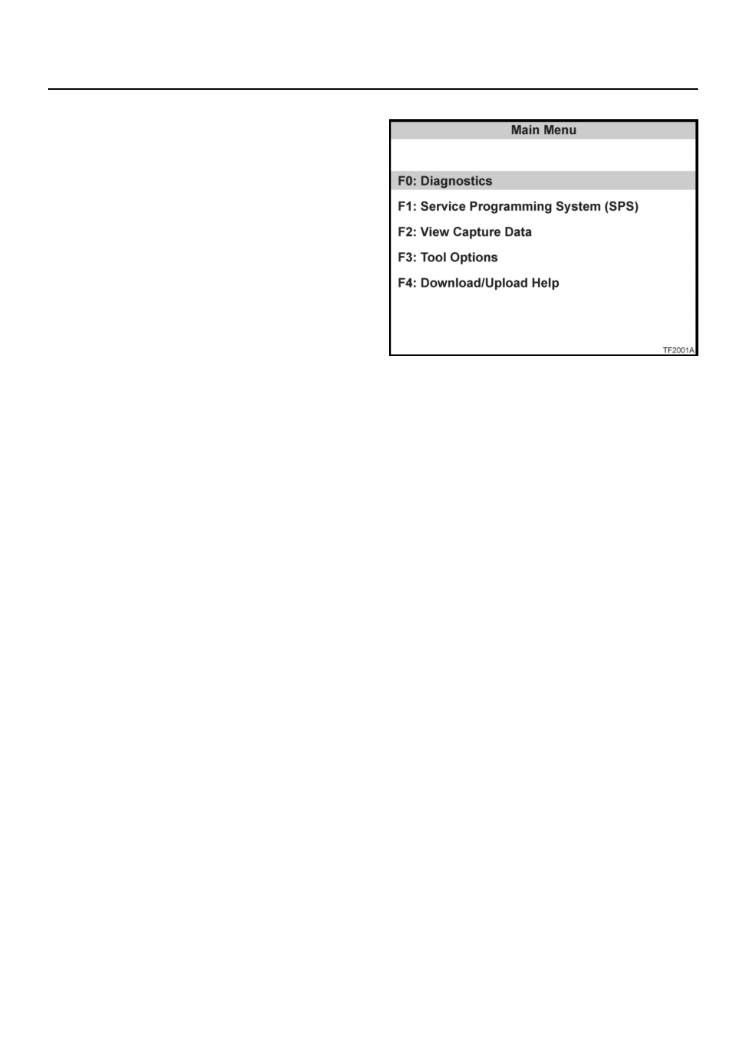
4. A selection can be made from the Main Menu,
either by using a function key or by using the arrow
keys to highlight a menu choice and pressing
ENTER.
•NOTE: You will then need to supply some additional
information to the TECH 2. This requires navigation
through a series of lists (called picklists). On some
menus or picklists, the user can use a function key to
make a menu selection, but most of the picklists
require using the selection and action keys. If a
mistake is made in the selection process, or if a
different application or function is desired, press EXIT
to back up one level. Within an application, there may
be soft keys which are available for use. These soft
keys allow access to additional tool functions without
exiting a current tool function. Soft keys are made up
of sets which will appear together. To see the next set
of soft keys, select the More soft key.
The TECH 2 Main Menu contains the following:
F0: Diagnostics
Contains all functions to test, diagnose, monitor and
program the different vehicle systems.
F1: Service Programming System (SPS)
SPS is used in conjunction with Technical
Information System (TIS) 2000 to program vehicle
control units.
F2: View Capture Data
Contains all functions to work with one or two
previously recorded snapshots on one or two
vehicles. This function is to enable the viewing of
captured data without a vehicle.
F3: Tool Options
Contains the TECH 2 self test, set clock, set units,
set screen contrast and Getting Started.
F4: Download/Upload Help
Contains help information on the downloading and
uploading from the TECH 2 to the TIS 2000 CD-
ROM.
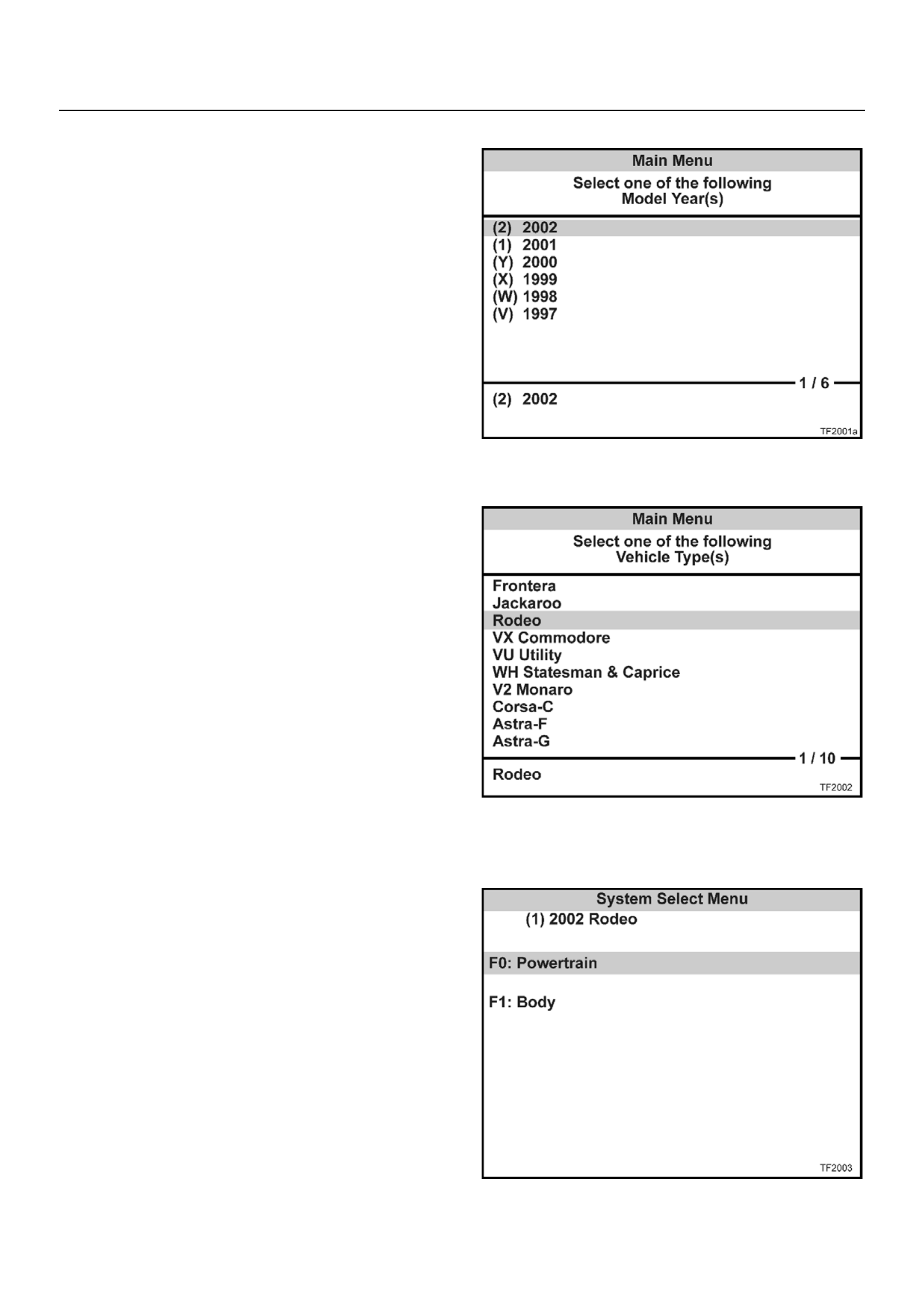
5. Select the correct Model Year with the arrow keys
and the press ENTER. The Vehicle identification
screen will then be displayed.
6. Select the correct Vehicle Type with the arrow keys
and the press ENTER. The System Select Menu
will then be displayed.
7. The desired system can be selected from the
System Select Menu with the function keys or with
arrow keys and then press ENTER.
F0:Powertrain contains all functions to test,
diagnose, and monitor the engine and transmission
systems that communicate with the Tech 2 via the
Powertrain Control Module (PCM).
F1: Chassis contains all functions to test,
diagnose, monitor the vehicles chassis systems;
TOD and ABS modules.
F2: Body contains all functions to test, diagnose,
monitor the instruments and Supplemental
Restraint System.

Once the test vehicle has been identified an
“Application (Powertrain) Menu" screen appears.
Please select the appropriate application.
The following table shows, which functions are used for
the available equipment versions.
F0: Diagnostic Trouble Codes
F0: Read DTC Info Ordered By Priority
F1: Clear DTC Information
F2: DTC Information
F0: History
F1: MIL SVS or Message Requested
F2: Last Test Failed
F3: Test Failed Since Code Cleared
F4: Not Ran Since Code Cleared
F5: Failed This Ignition
F1: Data Display
F0: Transmission Data
F1: TCC Data
F2: Snapshot
F3: Actuator Tests
F0: Lamps
F0: Check Light Test
F1: Power Lamp Test
F2: Winter Lamp Test
F3: AT Oil Temperature Lamp Test
F1: Solenoids
F0: Solenoid 2-3 Test
F1: Solenoid 1-2/3-4 Test
F2: TCC Solenoid Test
F3: Pressure Control Solenoid (PCS)
Diagnostic Trouble Codes
The purpose of the “Diagnostic Trouble Codes" mode
is to display stored TCM trouble codes.
When “Diagnostic Trouble Codes" is selected an
“Application Menu" screen appears.
Clear DTC Information
The purpose of the “Clear DTC Information" mode is to
command the clearing of stored TCM trouble codes.
When “Clear DTC Information" is selected, a “Clear
DTC Information", warning screen appears. This
screen informs you that by cleaning DTC's, “all stored
DTC information in controller will be erased".
Do you want to clear DTC's (Yes/No).
Press either the Yes or No key when answering.
After clearing codes, confirm system operation by test
driving the vehicle.
Allow the vehicle to shift through all four forward gears
in a manner which attempts to repeat the failure
condition.
NOTE: When the trouble has not been repaired and
the trouble code cannot be erased, check the vehicle
again.
DTC Information
When “DTC Information" is selected, an “Application
Menu" appears with a list of DTC information function
keys addressing DTC specifics and their origins.
Function key selections may vary for particular vehicle
and/or system.
Data Display
The purpose of the “Data Display" mode is to
continuously monitor data parameters.
The current actual values of all important sensors and
signals in the system are display through F1 mode.
When “Data Display" is selected an “Application Menu"
appears.
See “TRANSMISSION DATA" and “TCC DATA” on
next page.
Snapshot
When “Snapshot" is selected an “Application Menu"
appears.
When “Transmission Snapshot" application is selected
from the “Application Menu", a “Snapshot Menu"
appears, displaying several options. “Snapshot" options
may vary from one system to another.
“Snapshot" allows a recording of all vehicle
parameters. There parameters may then be replayed
at a future point in time.
This action allows you to focus on making the condition
occur, rather than trying to view all of the data in
anticipation of the fault. The snapshot will collect
parameter information around a trigger point that you
select.
When a snapshot is taken. It is recorded onto the
PCMCIA memory card. When the Tech2 is powered
down. Snapshots are not lost.
Actuator Tests
The purpose of “Actuator Tests" mode is to check for
correct operation of electronic system actuators.
Lamps
You can operate the lamps by pressing the ON and
OFF buttons.
Preconditions: P or N position
Solenoid
Solenoid S1(1-2/3-4), S2(2-3) and TCC Solenoid
(Torque Converter Clutch)
You can operate the solenoids by pressing the ON and
OFF buttons.
Preconditions: P or N position, no vehicle speed, no
engine speed
Pressure Control Solenoid (PCS)
You can operate the PC Solenoid by pressing the ON
and OFF buttons. ON will command a maximum
current of 1000 mA and OFF a minimum of 200 mA.
Preconditions: P or N position, no vehicle speed,
engine running

TRANSMISSION DATA
Item Unit Engine running at idle
Current Gear 1
Lock Up Inactive, Active Inactive
Selector Position Park
AT Output Speed (Automatic Transmission) RPM 0 RPM
Output Speed (Meter Signal Side) RPM 0 RPM
AT Input Speed (Automatic Transmission) RPM 0 RPM
Engine Speed RPM 695 ~ 745 RPM (UBS)
Vehicle Speed (Output Side) km/h 0 km/h
Throttle Position % 0%
Throttle Position Sensor V 0.25 ~ 0.45V
AT Oil Temperature (Automatic Transmission) °C, °F 70 ~ 80°C (158 ~ 176°F)
Shift Pattern
Desired PCS Pressure (Pressure Control
Solenoid) kPa
PCS Desired Current (Pressure Control Solenoid) mA
PCS Actual Current (Pressure Control Solenoid) mA
Overdrive Off Switch Off, On
Brake Switch Open 0V, Closed 12V Closed 12V
Winter Switch Open, Closed 0V Open
Power Switch Open, Closed 0V Open
Diagnostic Request Open, Closed Open
Winter Lamp Inactive 12V, Active 0V Inactive 12V
Power Lamp Inactive 12V, Active 0V Inactive 12V
Check Light Inactive 12V, Active 0V Inactive 12V
AT Oil Temperature Lamp (Automatic
Transmission) Inactive 12V, Active 0V Inactive 12V
Solenoid 2-3 Inactive 0V, Active 12V Inactive 0V
Solenoid 1-2/3-4 Inactive 0V, Active 12V Active 12V
TCC Solenoid (Torque Converter Clutch) Inactive 0V, Active 12V Inactive 0V

TCC DATA
Item Unit Engine running at idle
Current Gear 1
Lock Up Inactive, Active Inactive
AT Output Speed (Automatic Transmission) RPM 0 RPM
Output Speed (Meter Signal Side) RPM 0 RPM
AT Input Speed (Automatic Transmission) RPM 0 RPM
Engine Speed RPM 695 ~ 745 RPM (UBS)
Vehicle Speed (Output Side) km/h 0 km/h
Throttle Position % 0%
Gear Ratio :1 2.804
AT Oil Temperature (Automatic Transmission) °C, °F 70 ~ 80°C (158 ~ 176°F)
TCC Slip Speed RPM 695 ~ 745 RPM
TCC Solenoid Pressure Desired kPa 0 kPa
Desired TCC Solenoid Current mA 0 mA
Actual TCC Solenoid Current mA 0 mA

INTERMITTENT CONDITIONS
If the Tech2 displays a code as intermittent, or if after a test
drive a code does not reappear, the problem is most likely a
faulty electrical connection or loose wiring.
Terminals should always be the prime suspect.
Intermittent rarely occur in sophisticated electronic
components such as the Transmission Control Module (TCM).
When an intermittent problem is encountered, check suspect
circuits for:
Poor terminal to wire connection.
Terminals not fully seated in the connector body (backed
out).
Improperly formed or damaged terminals.
Loose, dirty, or corroded ground connections.
HINT: Any time you have an intermittent in more than one
circuit, check whether the circuits share a common
ground connection.
Pinched or damaged wires.
Electro-Magnetic Interference (EMI)
HINT: Check that all wires are properly routed away from
coil, and generator. Also check for improperl
y
installed electrical options, such as lights, 2-wa
y
radios, etc.
Use the F2: SNAPSHOT mode of the Tech2 to help isolate the
cause of an intermittent fault. The snapshot mode will record
information before and after the problem occurs. Set the
snapshot to "trigger" on the suspect code (or codes) or, if you
notice the reported symptom during test drive, trigger the
snapshot manually.
After the snapshot has been triggered, command the Tech2 to
play back the flow of data recorded from each of the various
sensors. Signs of an intermittent fault in a sensor circuit are a
sudden unexplainable jump in data values out of the normal
range.
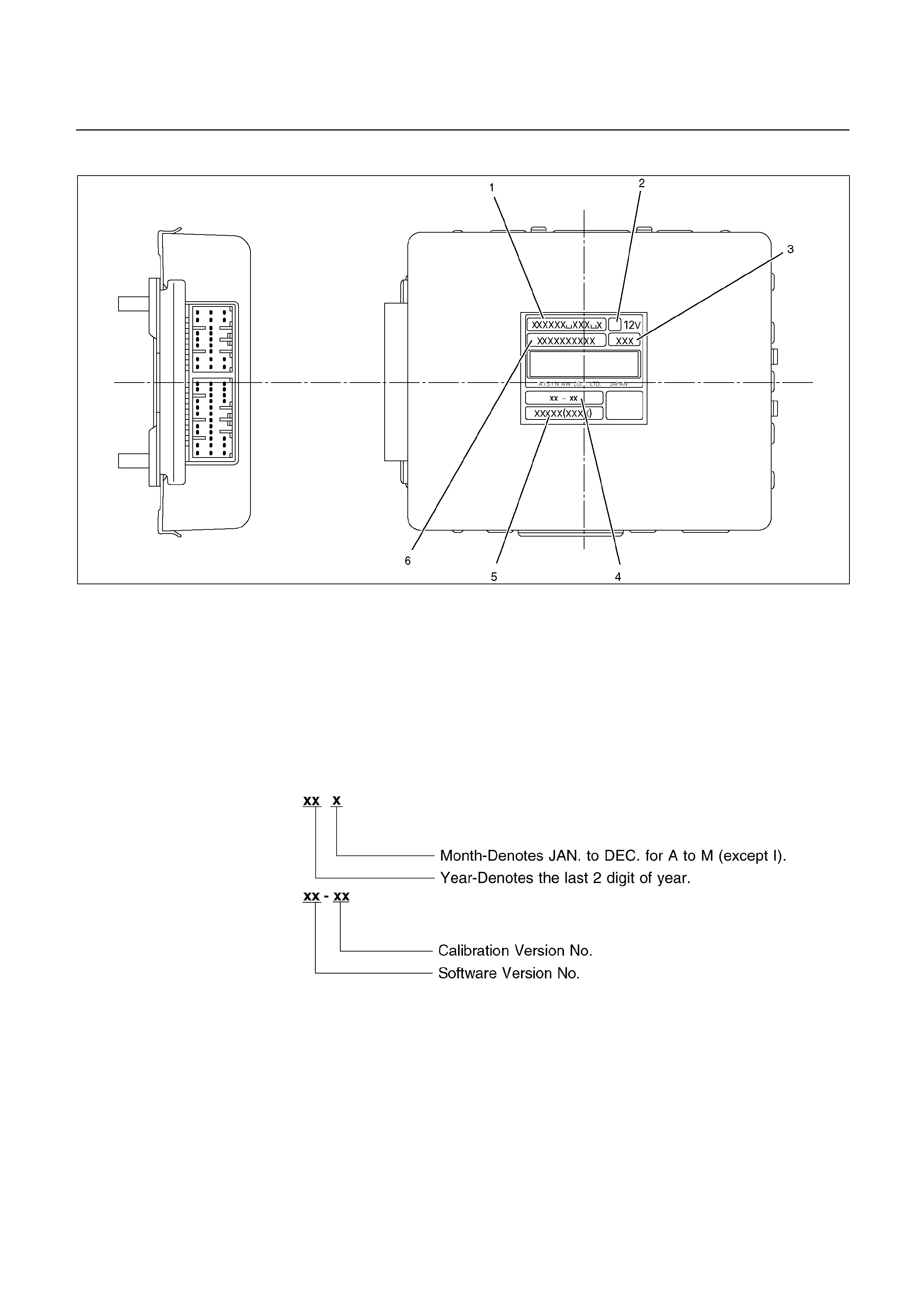
IDENTIFICATION OF TRANSMISSION CONTROL MODULE (TCM)
826R200032
Legend
1. HOLDEN Part No:
‘02UBS 8-97230-821-0
‘02TFS 8-97303-885-0
‘02TFR 8-97303-884-0
2. Calibration Code
3. Production Date:
4. Software Version No.:
5. Model Year, Vehicle Model, Engine Type

DIAGNOSTIC TROUBLE CODES (DTC) CHECK
DTC
NUMBER
FLASHING
CODE DESCRIPTION
P0120 21 ANALOG THROTTLE SIGNAL FAILURE (VTH) (FOR UBS)
P0502 24 SPEED METER SENSOR FAILURE (SP1)
P0705 17 GEAR SELECTOR FAILURE (PRND2L)
P0710 16 OIL TEMPERATURE SENSOR FAILURE (OT2)
P0717 14 INPUT REVOLUTION SENSOR FAILURE (NC0)
P0722 11 OUTPUT REVOLUTION SENSOR FAILURE (SP2)
P0727 13 ENGINE REVOLUTION SIGNAL FAILURE (NE)
P0743 33 TORQUE CONVERTER CLUTCH CONTROL LOCK-UP (ON/OFF) SOLENOID
FAILURE (SL)
P0748 35 PRESSURE CONTROL SOLENOID FAILURE (STH)
P0753 31 SOLENOID 1 FAILURE (S1)
P0758 32 SOLENOID 2 FAILURE (S2)
P1120 22 PWM THROTTLE SIGNAL FAILURE(TH) (FOR TFR/S)
P1121 23 ANALOG THROTTLE SIGNAL FAILURE (VREF, VGND) (FOR UBS)
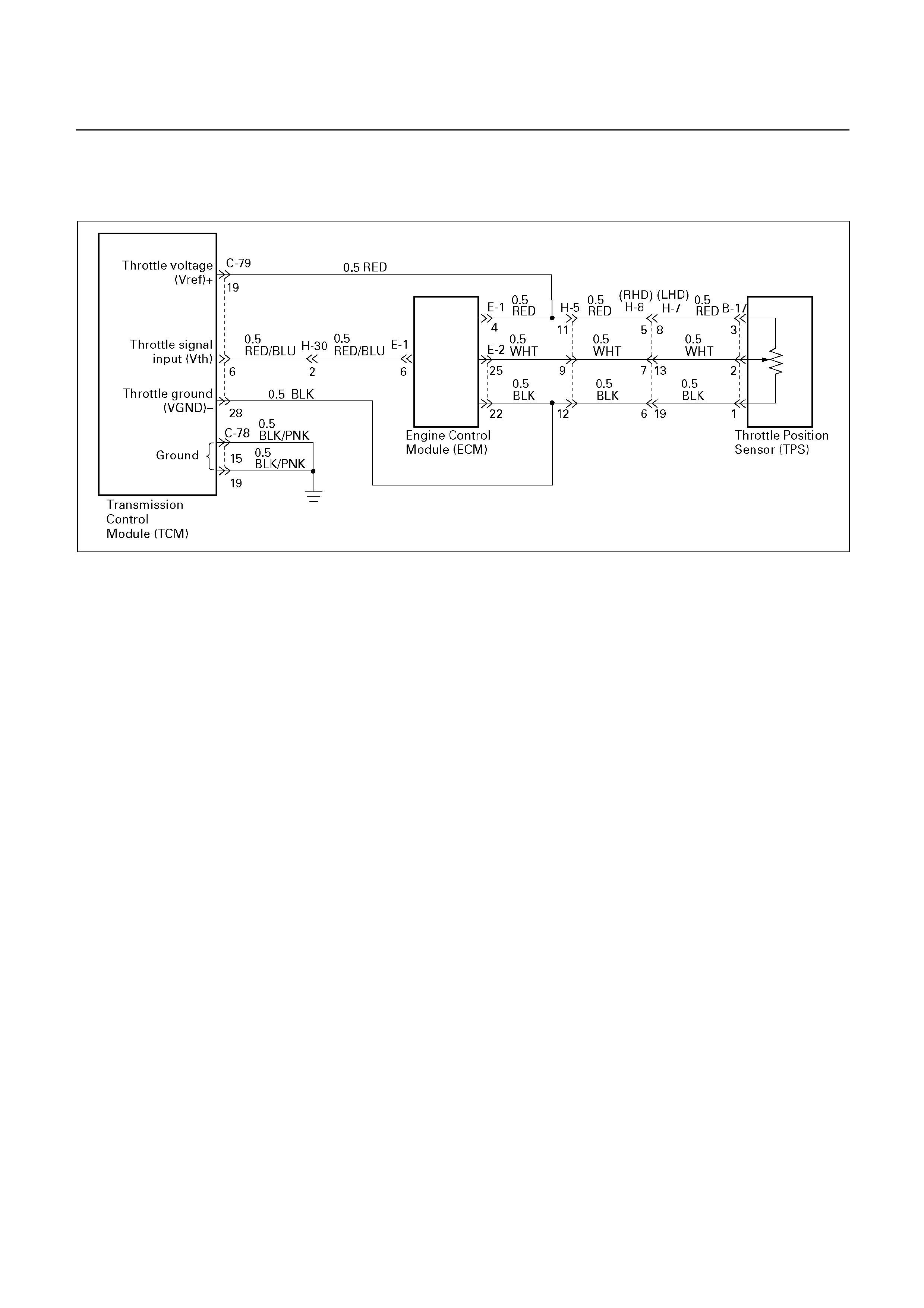
DTC P0120 (FLASHING CODE 21)
ANALOG THROTTLE SIGNAL FAILURE (VTH) (FOR UBS)
D07R200063
Circuit Description:
When the signal of the engine throttle position sensor
located on the accelerator pedal is supplied to the
TCM, the TCM judges the opening condition of the
throttle.
The shift point of the transmission is determined by this
opening condition of the throttle.
Fail-safe control:
The TCM controls fail-safe by detecting analog throttle
signal (VTH) failure.
Failure detection:
• When the throttle input voltage is detected less
than 0.112V or more than 4.417V for 2.0 seconds.
Contents of control:
At failure detection
• Throttle opening for line pressure control ... Throttle
opening 100%
• Throttle opening for shift control ... Throttle opening
0%
• Lock-up control inhibit
• Up hill and down hill control inhibit
• Squat control inhibit
At failure decision
Executes following items in addition to above
control items at failure detection.
• Blinks "CHECK TRANS" lamp
• Stores the failure information in failure-memory
Conditions of turning "CHECK TRANS" lamp
off:
Turns “CHECK TRANS” lamp off when judged 0km/h
by output revolution sensor after throttle signal input
voltage is detected more than 0.112V and less than
4.717V.
(however, uses 0 km/h judgment by back-up vehicle
speed at output revolution failure)
Reversion conditions from fail-safe:
At failure detection
Immediately recovers when the throttle input
voltage is detected more than 0.112V and less than
4.717V.
At failure decision
Recovers at the same time as the conditions of
turning “CHECK TRANS” lamp off are satisfied.
Test description:
The following numbers correspond to the step numbers
on the diagnostic chart.
1. Check that the throttle input voltage is 0.25 to
0.45V.
2. At this test, check that as the throttle opens, the
voltage goes up and that the voltage reaches 3.74
to 4.56V at the full open status.
6. Check the power supply voltage (4.75 – 5.25V) of
the throttle position sensor.

Diagnostic aids:
An intermittent may be caused by a poor connection,
rubbed through wire insulation or a wire broken inside
the insulation. Inspect related harness connector for
backed out terminals, improper mating, broken locks,
improperly formed or damaged terminals, poor terminal
to wire connection and damaged harness.
.

DTC P0120 (FLASHING CODE 21)
ANALOG THROTTLE SIGNAL FAILURE (VTH) (FOR UBS)
Step Action Value(s) Yes No
1
1. With the engine “OFF”, turn the ignition “ON”.
2. Connect a voltmeter between the TCM 28
pin connector terminal (6) and ground
terminal (28).
Is the voltage within the specified valve?
0.25 0.45 V Go to Step 2 Go to Step 3
2
Open the throttle fully.
Is the voltage within the specified value?
3.74 4.56 V The problem is
intermittent.
Refer to
“Diagnostic
aids”.
Go to Step 3
3
Connect a voltmeter between the ECM 32 pin
connector terminal (E1-6) and (E2-22).
Is the voltage within the specified value?
0.25 0.45 V Go to Step 4 Go to Step 6
4 Open the throttle fully.
Is the voltage within the specified value?
3.74 4.56 V Go to Step 5 Go to Step 6
5
1. Check the wiring harness between the TCM
28 pin connector terminal (6) and ECM 32
pin connector terminal (E1-6).
2. Or TCM is faulty.
Was a problem found and corrected?
Go to Step 9
6
1. Disconnect the TPS 3 pin connecter.
2. Connect a voltmeter between the TPS 3 pin
connector terminal (3) and (1).
Is the voltage within the specified value?
4.75 5.25 V Go to Step 7 Go to Step 8
7
Check the TPS connector. If OK, replace the
TPS.
Is the replacement complete?
Go to Step 9
8
Check the wiring harness between the TPS and
ECM. If OK, replace the ECM.
Is the replacement complete?
Go to Step 9
9
1. After the repair is complete, use the scan tool
to select “DTC”, then “clear Info” function.
2. Make a road running test for the vehicle.
3. Review the scan tool “DTC Info”.
Has the last test failed or is the current DTC
displayed?
Begin the
diagnosis
again.
Go to Step 1
System OK

DTC P0502 (FLASHING CODE 24)
SPEED METER SENSOR FAILURE (SP1)
UBS
D07R200056
TFR/S
D07L200001

Circuit description:
Speed information is provided by the speed meter
sensor to the meter.
In the meter, the pulses of the speed meter sensor are
converted to speed signals (pulses), and these signals
are output to the TCM and ECM(TF). The TCM
converts these pulse voltages to km/h signals.
Fail-safe control:
The TCM controls fail-safe by detecting speed meter
signal failure.
Failure detection:
• When not even 1 pulse is input in the speed meter
signal during the time 100 pulses are input in the
output revolution sensor signal.
• When not even 1 pulse is input in the speed meter
signal during the time 27 pulses are input in the
output revolution sensor signal.
Contents of control:
At failure detection
• Keeps the condition of transfer (High/Low
judgment) just before detection until vehicle speed
is 0km/h, and changes shift map to L4 map (3→4
UP None) at vehicle speed is 0km/h. (For UBS)
• Uses high oil temperature map according to shift
map priority at correct oil temperature control.
• Up hill and down hill control inhibit. (For UBS)
• Stores the failure information in failure -memory.
• The failure detection of oil temperature sensor
inhibit
At failure decision
Executes following items in adition to above control
items at failure detection.
• Blinks "CHECK TRANS" lamp
Conditions of turning "CHECK TRANS" lamp
off:
Turns "CHECK TRANS" lamp off when judged 0km/h
by speed meter sensor after more than 1 pulse are
input in the speed meter signal during the time 27
pulses are input in the output revolution sensor.
Reversion conditions from fail-safe:
At failure detection and decision
Recovers at the same time as the conditions of turning
“CHECK TRANS” lamp off are satisfied.
Test description:
The following numbers correspond to the step numbers
on the diagnostic chart.
2. The cause of DTC P0502 setting is due to the
operation fault of the speed meter.
3. Speed signals are output from the meter. The
sensor power supply is given from the TCM.
Diagnostic aids:
An intermittent may be caused by a poor connection,
rubbed through wire insulation or a wire broken inside
the insulation. Inspect related harness connector for
backed out terminals, improper mating, broken locks,
improperly formed or damaged terminals, poor terminal
to wire connection and damaged harness.

DTC P0502 (FLASHING CODE 24)
SPEED METER SENSOR FAILURE (SP1)
Step Action Value(s) Yes No
1
1. Lift the driving wheels.
2. With the engine idling in gear D range.
Is the Tech 2 displayed speed the specified
value?
0 km/h Go to Step 2 DTC P0502 is
intermittent.
If other DTCs
are not stored
in memory.
Refer to
“Diagnostic
aids”.
2 Does the speed meter operate? Go to Step 3 Go to Step 4
3
1. Open the throttle and increase the revolution
speed of the driving wheels
2. Measure the voltage between the TCM 28
pin connector terminal (7) and TCM 20 pin
connector ground terminal (15 or 19) with a
voltmeter.
Does the voltage vary intermittently in the
specified value?
1.4 about 5V
(AC) (Vehicle
speed 10-20 km/h)
Go to Step 5 Go to Step 6
4
The speed meter or speed meter sensor is
faulty.
Was a problem found and corrected?
Go to Step 7
5 The TCM connect is faulty or the TCM is faulty.
Was a problem found and corrected?
Go to Step 7
6
The wiring harness between the speed meter
and TCM is open or the speed meter sensor is
faulty.
Was a problem found and corrected?
Go to Step 7
7
1. After the repair is complete, use the scan tool
to select “DTC”, then “Clear Info” function.
2. Make the road running test for the vehicle.
3. Review the scan tool “DTC Info”.
Has the last test failed or is the current DTC
displayed?
Begin the
diagnosis
again.
Go to Step 1
System OK
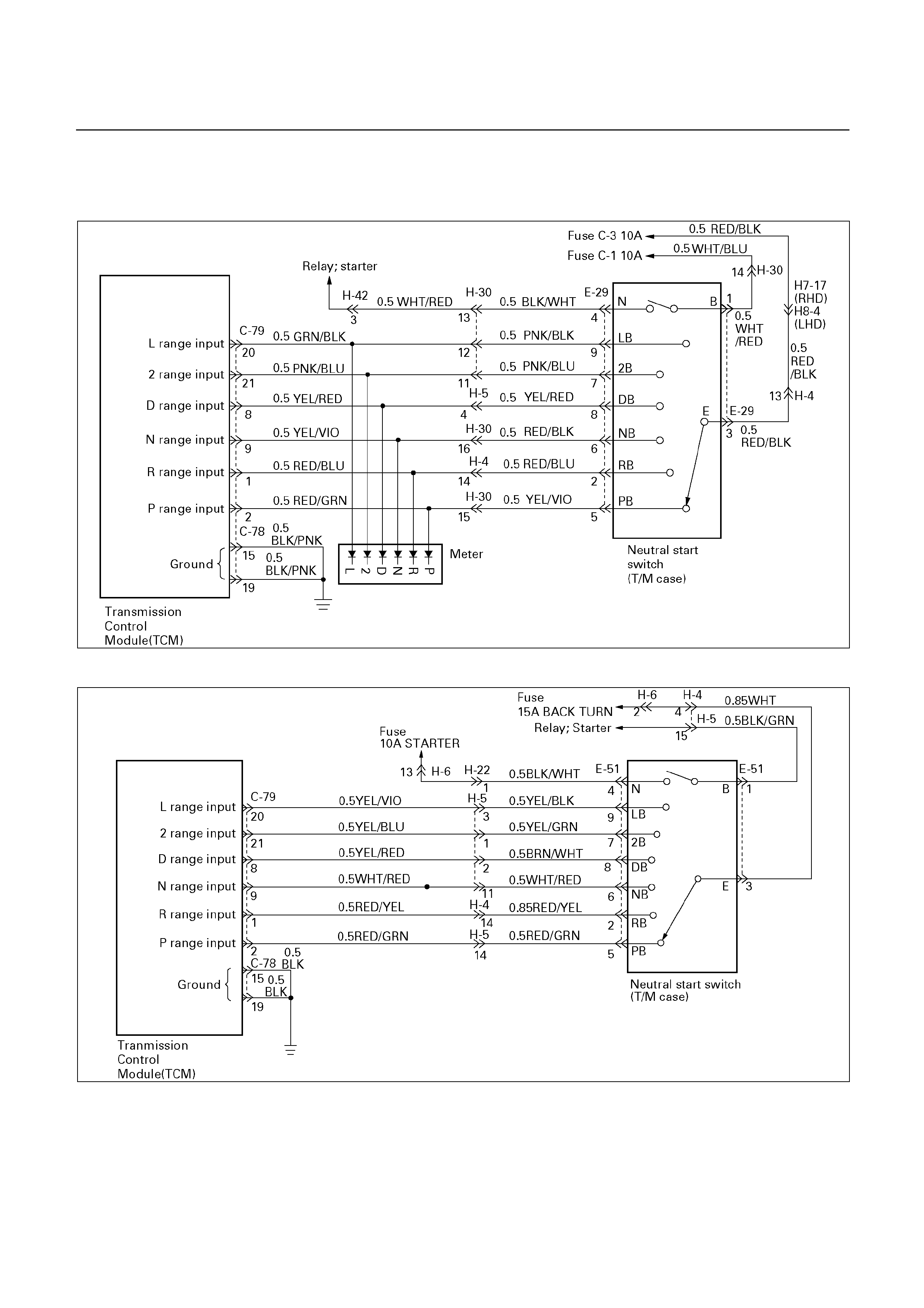
DTC P0705 (FLASHING CODE 17)
GEAR SELECTOR FAILURE (PRND2L)
UBS
D07R200057
TFR/S
D07L200002

Circuit description:
The neutral start switch gives the signals related to the
selector lever position (PRND2L) to the Transmission
Control Module (TCM). The neutral start switch turns
on when the select lever is shifted to the P, R, N, D, 2
or L range. The neutral start switch, which is connected
to the starter switch circuit, is available only when the
select lever is in the P or N range
The neutral start switch is connected to the
transmission manual shaft and installed in the
transmission case.
Fail-safe condition:
The TCM controls fail-safe by detecting selector
position switch failure.
Failure detection:
(1) OPEN:
• When all switches are OFF
• When the failure criteria continues for 30 seconds if
the vehicle speed which is calculated by output
revolution sensor is more than 30 km/h and the
engine revolution is more than 1500 rpm.
(2) SHORT:
• When more than two switches are ON at the same
time.
• When the failure criteria condition for 10 seconds.
Contents of control:
At failure detection
(1) OPEN: D range judgment
(2) SHORT: Judged by priority D>2>L>R>N>P
• Up hill and down hill control inhibit (For UBS)
• Winter mode inhibit (For UBS)
At failure decision
Excutes following items in addition to above control
items at failure detection.
• Blinks "CHECK TRANS" lamp
• Stores the failure information in failure-memory
• Reverse lockout control inhibit
Conditions of turning “CHECK TRANS” off:
Turns “CHECK TRANS” lamp off when only one of all
switches is ON.
Reversion conditions from fail-safe:
Turns “CHECK TRANS” lamp off when only one of all
switches is ON.
Test description:
The following numbers correspond to the step numbers
on the diagnostic chart.
1. It is judged whether the input signal received from
the neutral start switch by the TCM is proper or not.
5. The power status of the neutral start switch is
checked.
6. The continuity between neutral start switch
terminals and the continuity of the wire connected
to the neutral start switch are checked.
Diagnostic aids:
An intermittent may be caused by a poor connection,
rubbed through wire insulation or a wire broken inside
the insulation. Inspect related harness connector for
backed out terminals, improper mating, broken locks,
improperly formed or damaged terminals, poor terminal
to wire connection and damaged harness.

DTC P0705 (FLASHING CODE 17)
GEAR SELECTOR FAILURE (PRND2L)
Step Action Value(s) Yes No
1
1. With the engine "OFF", turn the ignition
"ON".
2. Connect a voltmeter to the each terminals of
the TCM 28 pin connector and TCM 20 pin
connector ground terminal (15 or 19).
3. Measure the voltage shifting the selector
lever to very position.
(Comparison with table 1)
Is the displayed voltage at every position
normal?
See table 1 Go to Step 2 Go to Step 3
2
1. Clear the TCM memory.
2. Make a running test. (Greater than 30
seconds).
Is DTC P0705 displayed by self-diagnosis?
Go to Step 4 The continuity
of wiring is
temporarily
faulty.
Refer to
“Diagnostic
aids”.
3 Is the displayed voltage at every position
abnormal?
Go to Step 5 Go to Step 6
4
The TCM is faulty or the continuity of wiring is
temporarily faulty.
Refer to "Diagnostic aids".
Was a problem found and corrected?
Go to Step 9
5
1. Check if there is any breaking in the fuse and
wire connected to the 10 pin connector
terminal (3) of the neutral start switch.
2. Check the adjusted condition of the neutral
start switch.
3. If no fault is found, replace the neutral start
switch.
Was a problem found and corrected?
Go to Step 9
6
1. Disconnect the 10 pin connector of the
neutral start switch.
2. Make a continuity check between each
terminals of the neutral start switch with an
ohmmeter.
Is the continuity at every position normal?
See table 2 Go to Step 7 Go to Step 8
7
The wiring harness between the TCM and
neutral start switch is open or shorted.
Was a problem found and corrected?
Go to Step 9
8 Replace the neutral start switch.
Is the replacement complete?
Go to Step 9
9
1. After the repair is complete, use the scan tool
to select "DTC", then "Clear Info" function.
2. Make a road running test for the vehicle.
3. Review the scan tool "DTC Info".
Has the last test failed or is the current DTC
displayed?
Begin the
diagnosis
again.
Go to Step 1
System OK
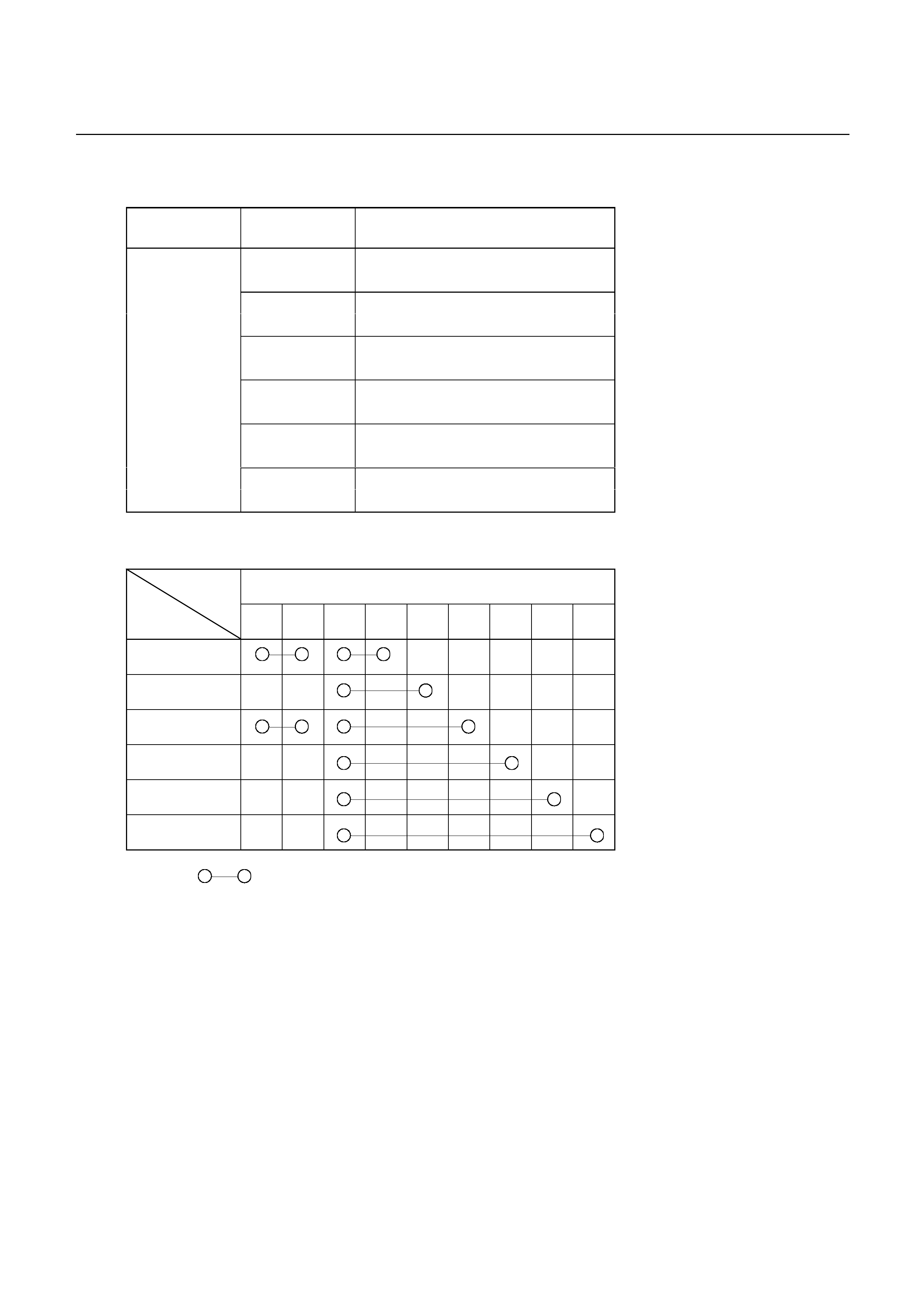
(Table 1)
TCM 20 pin
terminal (-)
TCM 28 pin
terminal (+) Voltage (V)
8-16: P range
2 1 or less: Other than P range
8-16: R range
1 1 or less: Other than R range
8-16: N range
9 1 or less: Other than N range
8-16: D range
8 1 or less: Other than D range
8-16: 2 range
21 1 or less: Other than 2 range
8-16: L range
15 or 19
20 1 or less: Other than L range
(Table 2)
Terminal Neutral start switch 10 pin connector
Range 1 4 3 5 2 6 8 7 9
P
R
N
D
2
L
Continuity
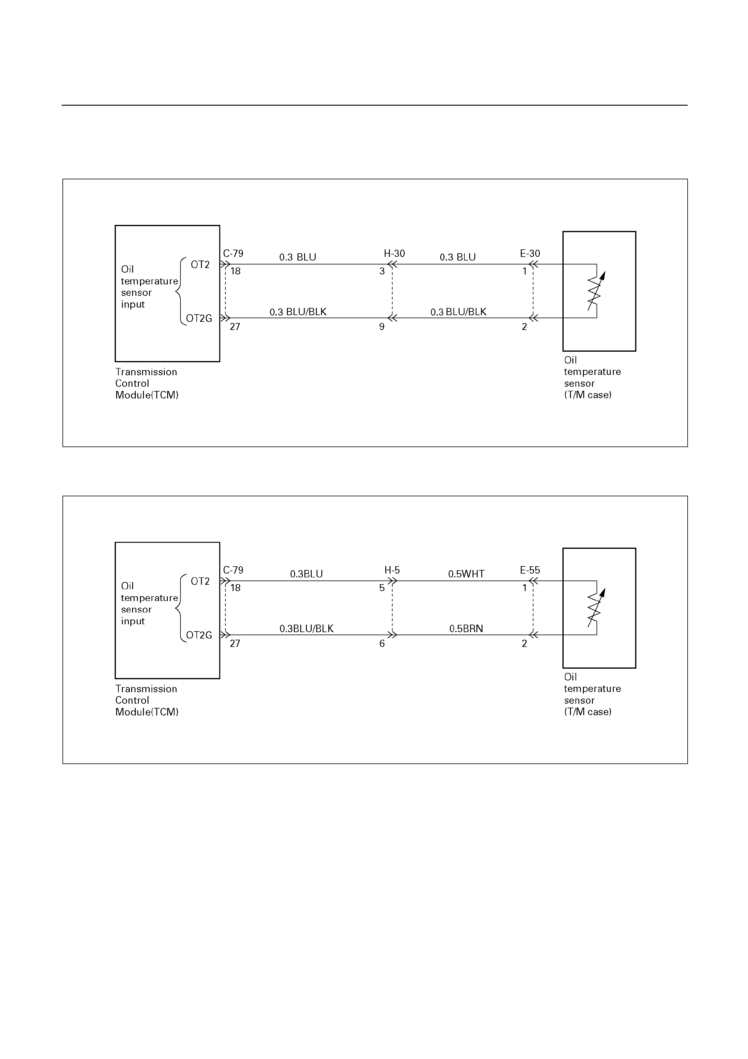
DTC P0710 (FLASHING CODE 16)
OIL TEMPERATURE SENSOR FAILURE (OT2)
UBS
D07R200058
TFR/S
D07L200003

Circuit Description:
The oil temperature sensor is a thermistor sensor that
is installed in the transmission case and converts
temperature changes into continuous electric signals,
then outputs them to the Transmission Control Module
(TCM). When the ATF temperature is low, the
resistance of the sensor (thermistor) goes up, so that
the voltage of the TCM signal becomes high.
As the ATF is gradually warmed, the resistance of the
sensor goes down and the voltage becomes low. At the
normal operating ATF temperature (80°C/176°F) of the
transmission, the voltage of the TCM is about 3.7V.
Fail-safe condition:
The TCM controls fail-safe by detecting oil temperature
sensor failure.
Failure detection:
Short detection
• When the A/D value is detected less than 10
(220°C) for 5 minutes continuously while normal
judgment is not satisfied from ignition on.
Open detection
• After 15 minites passed when the engine revolution
is more than 400 rpm and the selector position
switch is selected on R, D, 2, L range.
• When the change of the A/D value from engine
start is less than 15 and the minnum A/D value is
more than 1000 (-10°C) from engine start.
Contents of control:
At failure detection
• Changes shift map to HOT2 map
• Controls as A/T oil temperature 200°C
• Lock-up control inhibit
• Up hill and down hill control inhibit (For UBS)
• Blinks "CHECK TRANS" lamp
• Stores the failure information in failure-memory
At failure decision
• Same as failure detection.
Conditions of turning "CHECK TRANS" off:
Turns "CHECK TRANS" lamp off when judged 0km/h
by output revolution sensor after the normal area of oil
temperature 40°C – 150°C is detected for 10 sec
continuously.
Reversion conditions from fail-safe:
Recovers at the same time as the conditions of turning
“CHECK TRANS” lamp off are satisfied.
Test description:
The following numbers correspond to the step numbers
on the diagnostic chart.
1. Check that the voltage of the oil temperature
sensor varies with ATF temperatures.
3. Check that the resistance of the oil temperature
sensor varies with ATF temperatures.
Diagnostic aids:
An intermittent may be caused by a poor connection,
rubbed through wire insulation or a wire broken inside
the insulation. Inspect related harness connector for
backed out terminals, improper mating, broken locks,
improperly formed or damaged terminals, poor terminal
to wire connection and damaged harness.

DTC P0710 (FLASHING CODE 16)
OIL TEMPERATURE SENSOR FAILURE (OT2)
Step Action Value(s) Yes No
1
1. With the engine "OFF", turn the ignition
"ON".
2. Connect a voltmeter between the TCM 28
pin connector terminal (18) and (27).
Is the voltage as shown in the table?
See table Go to Step 2 Go to Step 3
2
1. Replace the TCM with a new one.
2. Make a running test.
Is DTC P0710 displayed by self-diagnosis?
Go to Step 4 The TCM is
faulty.
(TCM before
replacement)
Go to Step 9
3
1. Disconnect the TCM 28 pin connector.
2. Measure the resistance between the TCM 28
pin connecter terminal (18) and (27).
Is the resistance as shown in the table?
See table Go to Step 5 Go to Step 6
4
Check the wiring harness or connector
connection between the TCM and oil
temperature sensor.
Was a problem found and corrected?
Go to Step 9
5
The TCM is faulty or the continuity of wiring is
temporarily faulty.
Refer to "Diagnostic aids".
Was a problem found and corrected?
Go to Step 9
6
1. Disconnect the A/T 2 pin connector.
2. Measure the resistance between the A/T 2
pin connector terminal (1) and (2).
Is the resistance as shown in the table?
See table Go to Step 7 Go to Step 8
7
The wiring harness between the TCM and oil
temperature sensor connector is ground-shorted.
Was a problem found and corrected?
Go to Step 9
8 Replace the oil temperature sensor.
Is the replacement complete?
Go to Step 9
9
1. After the repair is complete, use the scan tool
the select "DTC", then "Clear Info" function.
2. Make a road running test for the vehicle.
3. Review the scan tool "DTC Info".
Has the last test failed or is the current DTC
displayed?
Begin the
diagnosis
again.
Go to Step 1
System OK
(Table)
ATF temperature (°C/°F) Voltage (V) Resistance (kΩ)
20/68 Approx. 4.7
80/176 Approx. 3.7
0.5 − 30
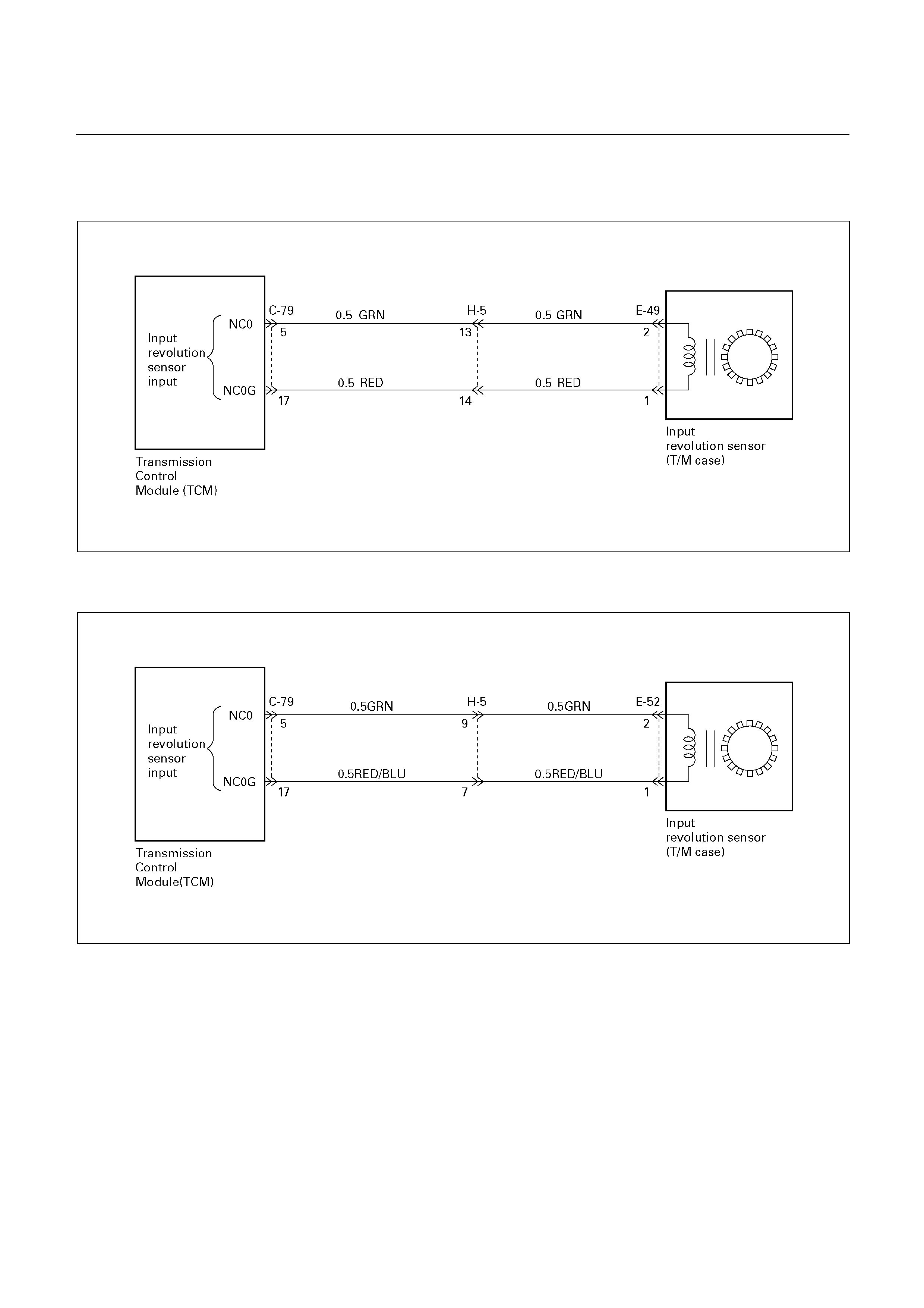
DTC P0717 (FLASHING CODE 14)
INPUT REVOLUTION SENSOR FAILURE (NC0)
UBS
D07R200059
TFR/S
D07L200004

Circuit description:
Input revolution information is provided to TCM by the
input revolution sensor. This sensor is located in the
transmission case.
The input revolution sensor is an electromagnetic pulse
pickup type that generates a speed signal according to
the revolution of the transmission OD direct clutch
drum.
As a result, the sensor sends a sine wave signal (AC)
to the TCM, which converts this sine wave signal (pulse
voltage) to a RPM signal.
Fail-safe control:
The TCM controls fail-safe by detecting input revolution
sensor failure.
Failure detection:
• When not even 1 pulse is input in the input
revolution sensor during the time 4 pulses are input
in the output revolution sensor.
• When the failure criteria is continuously 1000 times
from the time ignition is turned ON until it is turned
OFF.
Prohibits failure detection when at least one among the
following conditions is satisfied.
• When D, 2 and L range signal is not fixed.
• When output revolution is less than 775 rpm.
• When the failure detection timer T1 (*1) is less than
25 seconds.
• Solenoid S1, S2, and selector position switch is on
failure detection or decision.
• At 4th gear.
• When passed less than 10 seconds after shift
command output.
*1: Failure detection inhibit timer T1
Timer starts when D, 2 or L range are detected (fixation
signal).
Contents of control:
At failure detection
• Lock-up control inhibit
• Up hill and down hill control inhibit (For UBS)
At failure decision
Executes following items in addition to above
control items at failure detection.
• Blinks "CHECK TRANS" lamp
• Stores the failure information in failure-memory
Conditions of turning "CHECK TRANS" off:
At D, 2 or L range and not shifting, turns "CHECK
TRANS" lamp off when judged 0km/h by output
revolution sensor after more than 1 pulse input in the
input revolution sensor and finished vehicle speed
calculation during the time 4 pulse are input in the
output revolution sensor.
Reversion conditions from fail-safe:
Recovers at the same time as the conditions of turning
“CHECK TRANS” lamp off are satisfied.
Test description:
The following numbers correspond to the step numbers
on the diagnostic chart.
1. When the engine is running, a revolution signal is
input from the input revolution sensor to the TCM.
2. At this test, the continuity of circuit wiring and the
input revolution sensor is checked.
4. At this test, the continuity of the input revolution
sensor is checked.

Diagnostic aids:
An intermittent may be caused by a poor connection,
rubbed through wire insulation or a wire broken inside
the insulation. Inspect related harness connector for
backed out terminals, improper mating, broken locks,
improperly formed or damaged terminals, poor terminal
to wire connection and damaged harness.

DTC P0717 (FLASHING CODE 14)
INPUT REVOLUTION SENSOR FAILURE (NC0)
Step Action Value(s) Yes No
1
1. Turn the ignition "ON" and the engine "ON".
2. With the engine edling, connect a voltmeter
between the TCM 28 pin connector terminal
(5) and ground terminal (17).
Does the voltage rary in the specified value?
(The voltage increases in proportion to the
speed.)
0-3 V (AC)
or more
DTC P0707 is
intermittent.
If other codes
are not stored,
refer to
“Diagnostic
aids”.
Go to Step 2
2
1. Turn the ignition "OFF".
2. Disconnect the TCM 28 pin connector.
3. Connect an ohmmeter between the TCM 28
pin connector terminal (5) and (17).
Is the resistance within the specified value?
560-680 Ω
(at 20°C, 4×4)
387-473 Ω
(at 20°C, 4×2)
Go to Step 3 Go to Step 4
3
1. Replace the TCM with a new one.
2. Make a road running test for the vehicle.
Is DTC P0717 displayed?
Go to Step 5 Go to Step 7
4
1. Disconnect the 2 pin connector of the input
revolution sensor.
2. Measure the resistance between each
terminals of the input revolution sensor 2 pin
connector with an ohmmeter.
Is the resistance within the specified value?
560-680 Ω
(at 20°C, 4×4)
387-473 Ω
(at 20°C, 4×2)
Go to Step 6 Go to Step 5
5 Replace the input revolution sensor.
Is the replacement complete?
Go to Step 7
6
Check the wiring harness between the TCM and
input revolution sensor for an open or shorted.
Was a problem found and corrected?
Go to Step 7
7
1. After the repair is complete, use the scan tool
to select "DTC", then "Clear Info" function.
2. Make a road running test for the vehicle.
3. Reviews the scan tool "DTC Info".
Has the last test failed or is the current
DTC displayed?
Begin the
diagnosis
again.
Go to Step 1
System OK
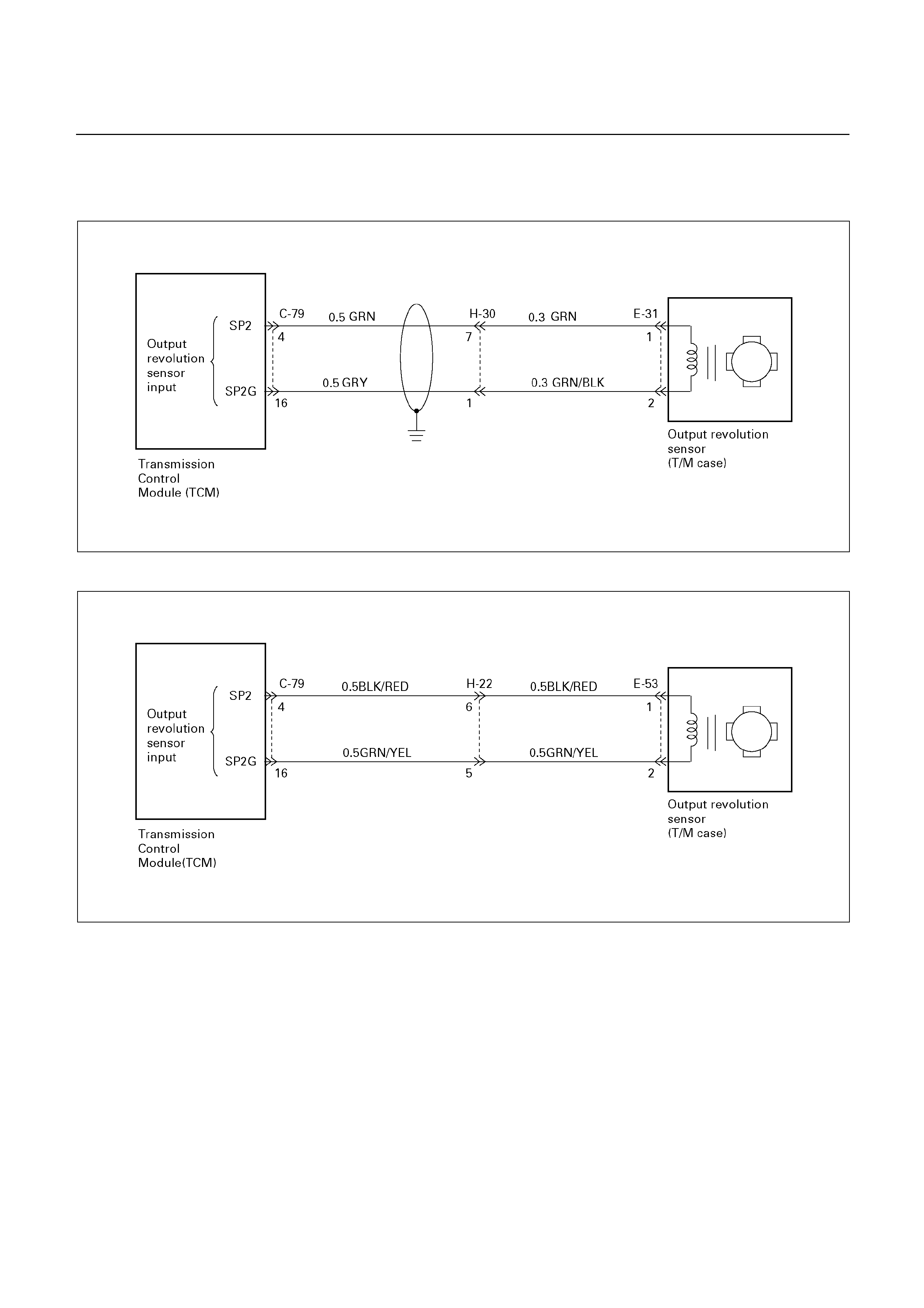
DTC P0722 (FLASHING CODE 11)
OUTPUT REVOLUTION SENSOR FAILURE (SP2)
UBS
D07R200060
TFR/S
D07L200005

Circuit description:
Vehicle speed information is provided to the TCM by
the output revolution sensor. This sensor is located in
the transmission adapter housing (4 4) or extension
housing (4 2). The output revolution sensor is an
electromagnetic pulse pickup type that generates a
speed signal according to the revolution of the
transmission output shaft. As a result, the sensor
sends a sine wave signal (AC) to the TCM, which
converts this sine wave signal (pulse voltage) to a km/h
signal.
Fail-safe control:
The TCM controls fail-safe by detecting output
revolution sensor failure.
Failure detection:
• When not even 1 pulse is input in the output
revolution sensor during the time 4 pulses are input
in the speed meter sensor.
• When the failure criteria is continuously 500 times
from the time ignition is turned ON until it is turned
OFF.
• Detection inhibit condition:
When speed meter sensor revolution is less than
80 rpm.
Contents of control:
At failure detection
• Uses the vehicle speed calculated by speed meter
sensor for shift control
• Keeps the condition of transfer (High/Low
judgment) just before detection until vehicle speed
is 0km/h, and changes shift map to L4 map
(3→4UP None) at vehicle speed 0km/h. (For UBS)
• Use high oil temperature map according to shift
map priority at correct oil temperature control.
• Squat control inhibit
• Up hill and down hill control inhibit (For UBS)
• Reverse lockout control inhibit
• Stores the failure information in failure-memory
At failure decision
Executes following items in addition to above
control items at failure detection.
• Blinks "CHECK TRANS" lamp
Conditions of turning "CHECK TRANS" off:
Turns "CHECK TRANS" lamp off when judged 0km/h
by speed meter sensor after more than 1 pulse input in
the output revolution sensor and finished vehicle speed
calculation during the time 4 pulse are input in the
speed meter sensor.
Reversion conditions from fail-safe:
Recovers at the same time as the conditions of turning
“CHECK TRANS” lamp off are satisfied.
Test description:
The following numbers correspond to the step numbers
on the diagnostic chart.
1. When the vehicle is running, a speed signal is input
from the output revolution sensor to the TCM.
2. At this test, the continuity of circuit wiring and the
output revolution sensor is checked.
4. At this test, the continuity of the output revolution
sensor is checked.
Diagnostic aids:
An intermittent may be caused by a poor connection,
rubbed through wire insulation or a wire broken inside
the insulation. Inspect related harness connector for
backed out terminals, improper mating, broken locks,
improperly formed or damaged terminals, poor terminal
to wire connection and damaged harness.

DTC P0722 (FLASHING CODE 11)
OUTPUT REVOLUTION SENSOR FAILURE (SP2)
Step Action Value(s) Yes No
1
1. Lift the driving wheels.
2. With the engine idling in gear, connect a
voltmeter between the TCM 28 pin connector
terminal (4) and ground terminal (16).
Does the voltage vary in the specified value?
(The voltage increase in proportion to the
speed.)
0-3 V or more DTC P0722 is
intermittent. If
other codes
are not stored,
refer to
"Diagnostic
aids".
Go to Step 2
2
1. Turn the ignition "OFF".
2. Disconnect the TCM 28 pin connector.
3. Connect an ohmmeter between the TCM 28
pin connector terminal (4) and (16).
Is the resistance within the specified value?
560-680
(at 20 )
Go to Step 3 Go to Step 4
3
1. Replace the TCM with a new one.
2. Make a road running test for the vehicle.
Is DTC P0722 displayed?
Go to Step 5 The TCM is
faulty.
(TCM before
replacement)
Go to Step 7
4
1. Disconnect the 2 pin connector of the output
revolution sensor.
2. Measure the resistance between each
terminals of the 2 pin connector with an
ohmmeter.
Is the resistance within the specified value?
560-680
(at 20 )
Go to Step 6 Go to Step 5
5 Replace the output revolution sensor.
Is the replacement complete?
Go to Step 7
6
Check the wiring harness between the TCM and
output revolution sensor for an open or shorted.
Was a problem found and corrected?
Go to Step 7
7
1. After the repair is complete, use the scan tool
to select "DTC", then "Clear Info" function.
2. Make a road running test for the vehicle.
3. Review the scan tool "DTC Info".
Has the last test failed or is the current DTC
displayed?
Begin the
diagnosis
again.
Go to Step 1
System OK
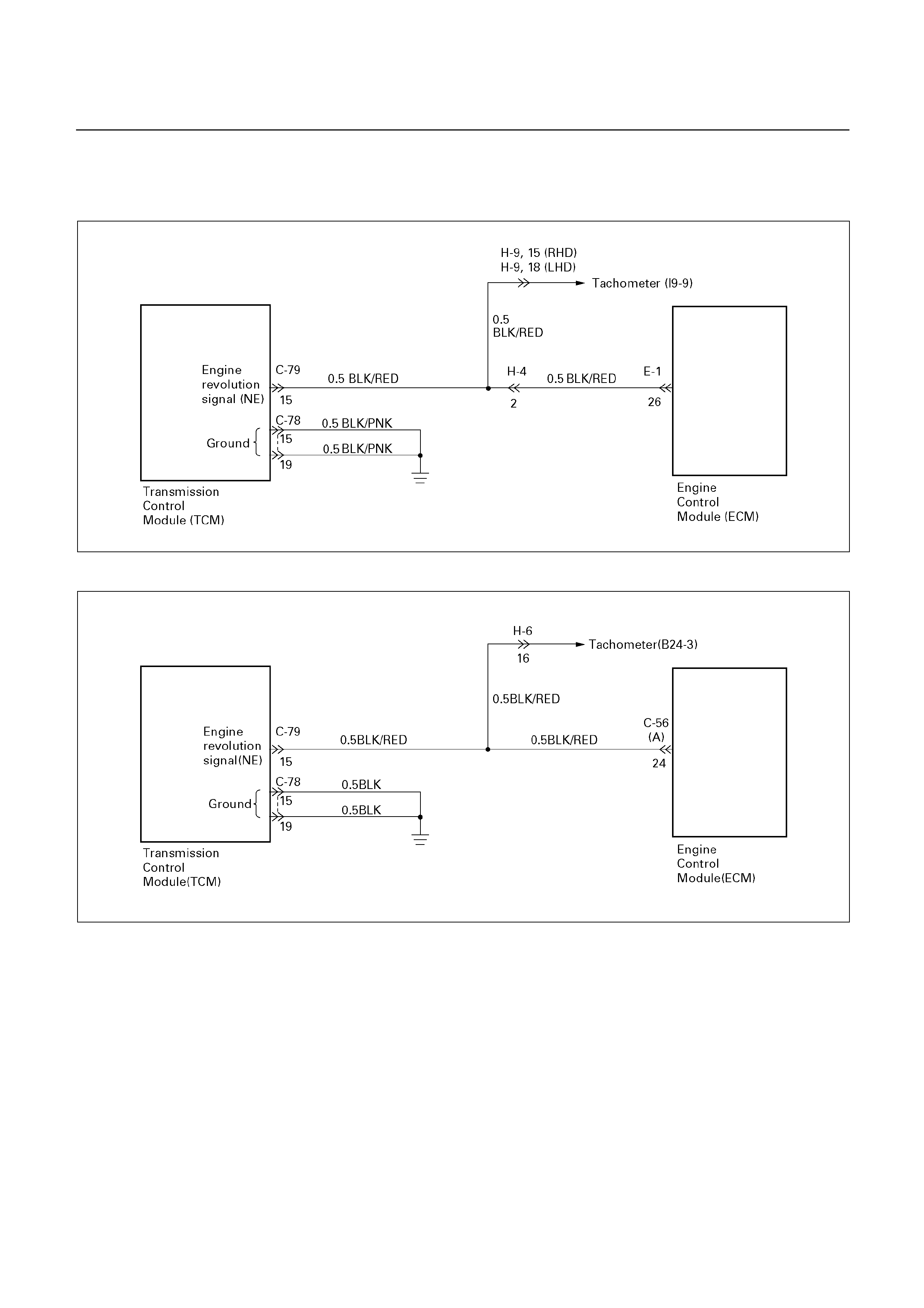
DTC P0727 (FLASHING CODE 13)
ENGINE REVOLUTION SIGNAL FAILURE (NE)
UBS
D07R200061
TFR/S
D07L200006

Circuit description:
Engine revolution (rpm) signals are sent from Engine
Control Module (ECM) to the Transmission Control
Module (TCM).
The engine speed sensor is an electromagnetic pulse
pickup type that generates signals when the flywheel
gear revolves (2 pulses at a single revolution of the
flywheel gear).
The TCM converts these sine wave signals into engine
revolution (RPM) signals.
Fail-safe control:
The TCM controls fail-safe by detecting engine
revolution sensor failure.
Failure detection:
• When input revolution is more than 2000 rpm
• When not even 1 pulse is input in the engine
revolution signal during 5 seconds
• Detection inhibit condition: At 4th gear
Contents of control:
At failure detection
• Up hill and down hill control inhibit (For UBS)
• Oil temperature sensor failure detection inhibit
• Blinks "CHECK TRANS" lamp
• Stores the failure information in failure memory.
At failure decision
Same as failure detection
Conditions of turning "CHECK TRANS" lamp
off:
Turns "CHECK TRANS" lamp off when judged 0km/h
by speed meter sensor after the engine revolution
signal pulses are input 250 pulses normally.
(however, uses 0 km/h judgment by back-up vehicle
speed at output revolution failure)
Reversion conditions from fail-safe:
Recovers at the same time as the conditions of turning
“CHECK TRANS” lamp off are satisfied.
Test description:
The following numbers correspond to the step numbers
on the diagnostic chart.
2. Engine revolution signals are input from the ECM
into the TCM.
3. When the engine idling, voltage fluctuates with (AC
intermittent) range of less than 1.4V ⇔ 9 ∼ 16V.
Diagnostic aids:
An intermittent may be caused by a poor connection,
rubbed through wire insulation or a wire broken inside
the insulation. Inspect related harness connector for
backed out terminals, improper mating, broken locks,
improperly formed or damaged terminals, poor terminal
to wire connection and damaged harness.

DTC P0727 (FLASHING CODE 13)
ENGINE REVOLUTION SIGNAL FAILURE (NE)
Step Action Value(s) Yes No
1
1. Clear the TCM memory.
2. Turn the ignition "ON" and start the engine.
3. With the engine "OFF", turn the ignition
"ON".
Is DTC P0727 displayed by self-diagnosis?
Go to Step 2 DTC P0727
was
temporarily
stored into
TCM memory.
Refer to
"Diagnostic
aids".
2
1. With the engine "OFF", turn the ignition
"ON".
2. Connect a voltmeter to the TCM 28 pin
connector terminal (15) and TCM 20 pin
connector ground terminal (15 or 19).
Is the voltage within the specified value?
9-16V Go to Step 3 Go to Step 4
3
1. With the ignition "ON" and the engine "ON".
2. Connect a voltmeter between the TCM 28
pin connector terminal (15) and TCM 20 pin
connector ground terminal (15 or 19).
Does the voltage vary in the specified value at
the engine idling?
Less than
1.4-9 16 V
(AC intermittently)
Go to Step 5 Go to Step 6
4
Check the wiring harness between the TCM and
ECM for breaking or voltage shorted.
Was a problem found and corrected?
Go to Step 7
5
Check the TCM connection. If OK, replace the
TCM.
Is the replacement complete?
Go to Step 7
6
Check the wiring harness between the TCM and
ECM for ground shorted. If OK, the ECM or the
engine revolution sensor is faulty.
Was a problem found and corrected?
Go to Step 7
7
1. After the repair is complete, use the scan tool
to select "DTC", then "Clear Info" function.
2. Make a road running, test for the vehicle.
3. Review the scan tool "DTC Info".
Has the last test failed or is the current DTC
displayed?
Begin the
diagnosis
again.
Go to Step 1
System OK
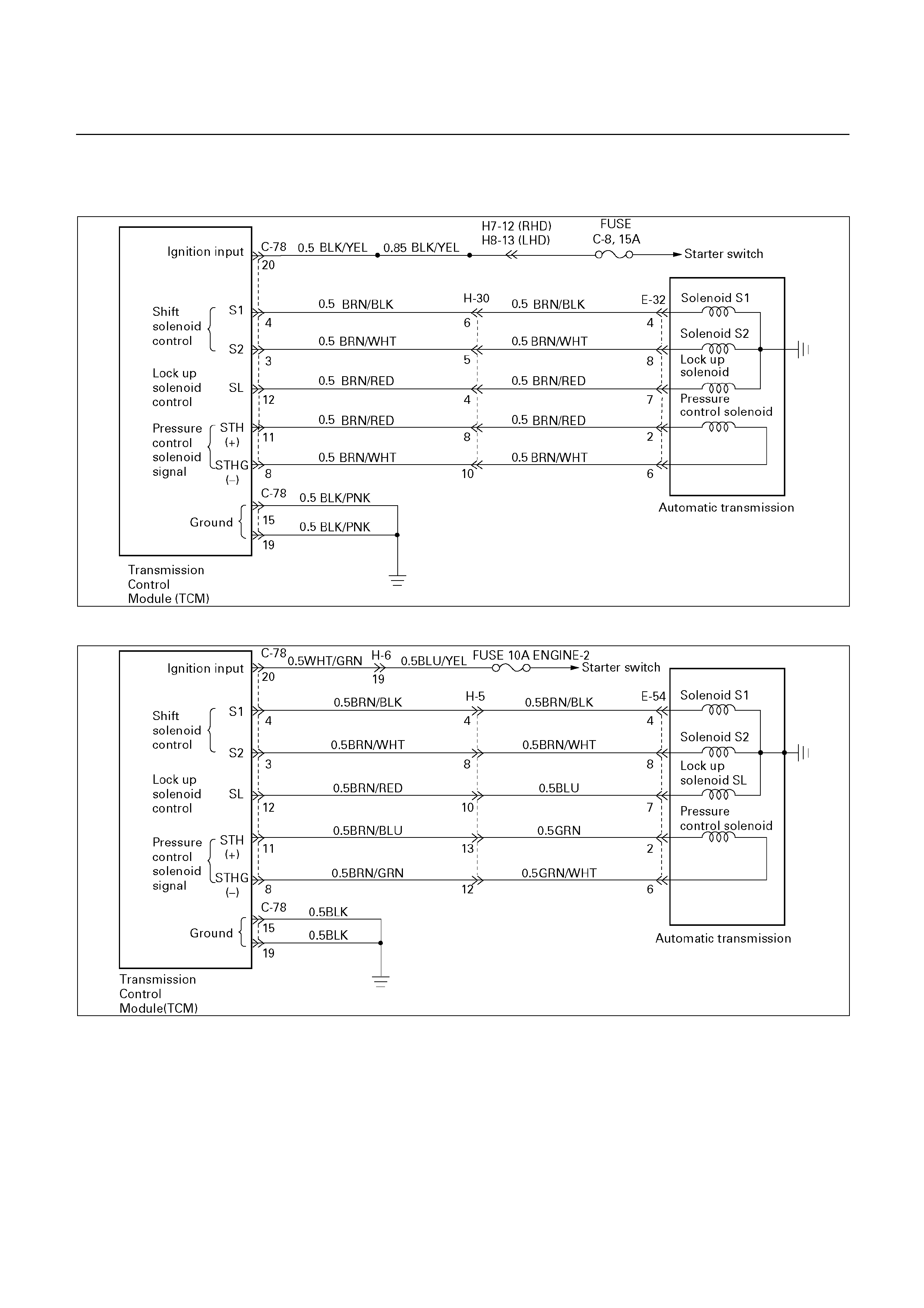
DTC P0743 (FLASHING CODE 33) TORQUE CONVERTER CLUTCH
CONTROL LOCK-UP (ON/OFF) SOLENOID FAILURE (SL)
UBS
D07R200062
TFR/S
D07L200007

Circuit description:
The lock-up solenoid SL of the torque converter clutch
(TCC) controls the lock-up clutch by a signal according
to the lock-up range judgement of the TCM when the
vehicle runs.
This function can improve the fuel consumption to
almost the same extent as the manual transmission.
The lock-up solenoid SL is put into B+ by the TCM, so
that the solenoid is actuated with the result of lock-up.
Fail-safe control:
The TCM controls fail-safe by detecting SL solenoid
failure.
Failure detection:
GND SHORT detection
• When SHORT detection continues for 0.3 sec.
• When SHORT failure detection continues 8 times.
Open detection
• When OPEN detection continues for 0.5 sec.
• When OPEN failure detection continues 8 times.
Contents of control:
At failure detection
• Lock-up control inhibit
• If + B short failure is detected, keeps 1st gear when
the vehicle speed calculated by output revolution
sensor is less than 10km/h to prevent stall.
(Canceled at more than 15km/h)
At failure decision
• Executes following items in addition to above
control items at failure detection.
• Stores the failure information in failure-memory.
Conditions of turning “CHECK TRANS” lamp
off:
None
Reversion conditions from fail-safe:
When a normal condition is judged by rechecking on
the state of lock-up ON/OFF
Test description:
The following numbers correspond to the step numbers
on the diagnostic chart.
1. When the key is ON, the voltage between the TCM
20 pin connector terminals (12) and (15 or 19) is
1.0 V or less.
2. When the gear is of the 2nd speed in the D range
and the throttle opening is about 50% at a higher
speed than about 40km/h, the TCM supplies 8 to
16 V, so that the solenoid is actuated with the result
of lock-up.
3.5.7.8. The resistance range of the solenoid is 11 to
15Ω (at 20°C).
Diagnostic aids:
In case of faulty connection, open or shorted circuit. to
the TCM 20 pin connector terminal (12), DTC P0743 is
displayed. A intermittent failure may be caused by a
poor connection, rubbed through wire insulation or a
wire broke inside the insulation.

DTC P0743 (FLASHING CODE 33) TORQUE CONVERTER CLUTCH
CONTROL LOCK-UP (ON/OFF) SOLENOID FAILURE (SL)
Step Action Value(s) Yes No
1
1. With the engine "OFF", turn the ignition "ON"
after warming up.
2. Connect a voltmeter between the TCM 20
pin connector terminal (12) and ground
terminal (15 or 19).
Is the voltage less than the specified value?
1 V Go to Step 2 Go to Step 3
2
1. Lift the driving sheels and support them.
2. At the D range and 2nd speed gear.
3. Make a test at a speed of about 40 km/h or
more with 50% or more opening of the
throttle.
Is the voltage between the TCM 20 pin connector
terminal (12) and ground terminal (15 or 19)
within the specified value?
8-16V Go to Step 4 Go to Step 5
3
1. Turn the ignition "OFF".
2. Disconnect the TCM 20 pin connector.
3. Measure the resistance between the terminal
(12) and ground.
Is the resistance within the specified value?
11-15Ω
(at 20 )
Go to Step 6 Go to Step 7
4
1. Clear the TCM memory.
2. Make a running test.
Is DTC P0743 displayed by self-diagnosis?
Go to Step 6 The continuity
of wiring is
intermittent.
Refer to
"Diagnostic
aids".
5
1. Turn the ignition "OFF".
2. Disconnect the TCM 20 pin connector.
3. Measure the TCM 20 pin connector terminal
(12) and ground.
Is the resistance within the specified value?
11-15Ω
(at 20 )
Go to Step 6 Go to Step 8
6
The TCM is faulty or the continuity of wiring
harness is intermittent.
Was a problem found and corrected?
Go to Step 12
7
Disconnect the A/T 8 pin connector.
Is the resistance between the lock-up solenoid
connector terminal (7) and ground within the
specified value?
11-15Ω
(at 20 )
Go to Step 9 Go to Step 10
8
Disconnect the A/T 8 pin connector.
Is the resistance between the lock-up solenoid
connector terminal (7) and ground within the
specified value?
11-15Ω
(at 20 )
Go to Step 11 Go to Step 10
9
Check the wiring harness between the TCM 20
pin connector terminal (12) and A/T 8 pin
connector terminal (7) for open.
Was a problem found and corrected?
Go to Step 12

Step Action Value(s) Yes No
10 Replace the lock-up solenoid (SL).
Is the replacement complete?
Go to Step 12
11
Check the wiring harness between the TCM 20
pin connector terminal (12) and A/T 8 pin
connector terminal (7) for ground shorted.
Was a problem found and corrected?
Go to Step 12
12
1. After the repair is complete, use the scan tool
to select "DTC", then "Clear Info" function.
2. Make a road running test for the vehicle.
3. Review the scan tool "DTC Info".
Has the last failed or is the current DTC
displayed?
Begin the
diagnosis
again.
Go to Step 1
System OK
DTC P0748 (FLASHING CODE 35)
PRESSURE CONTROL SOLENOID FAILURE (STH)
UBS
D07R200062
TFR/S
D07L200007

Circuit description:
The pressure control solenoid is a PWM duty control
solenoid located in the valve body.
The pressure control solenoid is a TCM-controled
device used to regulate transmission throttle pressure
by energizing current from the TCM.
Fail-safe control:
The TCM controls fail-safe by detecting pressure
control solenoid failure.
Failure detection:
IG short failure
• When the feedback A/D value is more than 1020
for 500 milli-second continuously.
• Detection inhibit condition: Prohibition during 1
second after reversion from open failure, because
the possibility of the mis-detection is high.
Open failure (Including GND Short)
• When the feedback A/D value is less than 15 for
more than 70 milli-second continuously, judges as
faliure, and turns the current of target output off,
after 1.5 second passed turns the current of target
value to normal. The A/D value is checked, and this
operation is repeated during 70 milli-second again.
• When it continues for 12.5 second in total.
Contents of control:
At failure detection
• Lock-up control inhibit
• Up hill and down hill control inhibit (For UBS)
• Squat control inhibit
At failure decision
• Executes following items in addition to above
control items at failure detection.
• Turns Solenoid power supply OFF
• Blinks "CHECK TRANS" lamp
• Stores the failure information in failure memory
*Prohibits failure detection of S1, S2, SL, STH, selector
position switch, and oil temperature sensor.
Conditions of turning "CHECK TRANS" off:
Turns "CHECK TRANS" lamp off after ignition is turned
ON→ OFF→ ON.
Reversion conditions from fail-safe:
At failure detection
When IG short failure···The feedback A/D value is
less than 1020 for 1 second continuously.
When open failure···Detection criteria is not
satisfied or the feedback A/D value is more than 15
for 1 second continuously.
At failure decision
Recovers at the same time as the conditions of
turning “CHECK TRANS” lamp off are satisfied.
Test description:
The following numbers correspond to the step numbers
on the diagnostic chart.
1. The solenoid resistance is within the range of 5 to
5.6Ω. (at 20°C)
2. This test checks for shorted circuit at the TCM.

Diagnostic aids:
An intermittent may be caused by a poor connection,
rubbed through wire insulation or a wire broken inside
the insulation. Inspect related harness connector for
backed out terminals, improper mating, broken locks,
improperly formed or damaged terminals, poor terminal
to wire connection and damaged harness.

DTC P0748 (FLASHING CODE 35)
PRESSURE CONTROL SOLENOID FAILURE (STH)
Step Action Value(s) Yes No
1
1. Turn the ignition "OFF".
2. Disconnect the TCM 20 pin connector.
3. Connect an ohmmeter between the TCM 20
pin connector terminal (11) and (8).
Is the resistance within the specified value?
5-5.6Ω (at 20°C) Go to Step 2 Go to Step 3
2
1. Connect an ohmmeter between the TCM 20
pin connector terminal (11) and ground
terminal (15 or 19).
2. Then, connect between the TCM 20 pin
connector terminal (11) and ignition terminal
(20).
3. Then, connect TCM 20 pin connector
terminal (8) and ground terminal (15 or 19),
then between TCM 20 pin connector
terminal (8) and ignition terminal (20).
Does display a short circuit?
Go to Step 4 The problem is
intermittent.
Refer to
"Diagnostic
aids".
3
1. Disconnect the A/T 8 pin connector.
2. Connect an ohmmeter between the A/T 8 pin
connector terminal (2) and (6).
Is the resistance within the specified value?
5-5.6Ω (at 20°C) Go to Step 5 Go to Step 6
4 Repair the short circuit.
Is the repair complete?
Go to Step 7
5
Repair the wiring harness for open between TCM
20 pin connector and A/T 8 pin connector.
Is the repair complete?
Go to Step 7
6
1. Check the wiring harness for open between
A/T 8 pin connector and pressure control
solenoid.
2. If OK, replace pressure control solenoid
(valve body assembly).
Go to Step 7
7
1. After the repair is complete, use the scan tool
to select "DTC", then "Clear Info" function
2. Make a road running test for the vehicle.
3. Review the scan tool "DTC Info".
Has the last test failed or is the current DTC
displayed?
Begin the
diagnosis
again.
Go to Step 1
System OK

DTC P0753 (FLASHING CODE 31) SOLENOID 1 FAILURE (S1)
UBS
D07R200062
TFR/S
D07L200007

Circuit description:
The shift solenoid S1 changes the hydraulic route with
the signals from the TCM according to the vehicle
speed and the throttle opening to control shifting. When
the solenoid S1 or S2 fails, the hydraulic circuit is
mechanically operated as a backup.
Fail-safe control:
The TCM controls fail-safe by detecting S1, S2 shift
solenoid failure.
Failure detection:
GND SHORT detection
• When SHORT detection continues for 0.3 sec.
• When SHORT failure detection continues 8 times.
Open detection
• When OPEN detection continues for 0.5 sec.
• When OPEN failure detection continues 8 times.
Contents of control:
At failure detection
• Lock-up control inhibit
• Up hill and down hill control inhibit (For UBS)
• Squat control inhibit
• Changes solenoid output pattern as following figure
The shift theory at shift solenoid failure
Normal S1 failure S2 filure S1 and S2 failure
Shift
lever
Position Gear S1 S2 Gear S1 S2 Gear S1 S2 Gear S1 S2
1 ×
××
× 1
2
3 ×
××
×
3
×
××
×
D
O/D ×
××
× ×
××
× O/D
×
××
×
O/D
×
××
×
O/D
1 ×
××
× 1
2
2
3 ×
××
×
3
O/D ×
××
×
3
1 ×
××
× 1
L
2
3
O/D
3
At failure decision
Executes following items in addition to above control
items at failure detection.
• Turns Solenoid power supply OFF
• Blinks "CHECK TRANS" lamp
• Stores the failure information in failure-memory
*Prohibits failure detection of S1, S2, SL, STH,
Selector position switch, and Oil temp. sensor.
Conditions of turning "CHECK TRANS" off:
Turns "CHECK TRANS" lamp off after ignition is turned
ON→ OFF→ ON.
Reversion conditions from fail-safe:
At failure detection
When a normal judgment is obtained by rechecking
during shifting.
At failure decision
Recovers at the same time as the conditions of
turning “CHECK TRANS” lamp off are satisfied.
Test description:
The following numbers correspond to the step numbers
on the diagnostic chart.
1. With the key "ON", the voltage between the TCM
20 pin connector terminals (4) and (15 or 19) is 8 to
16V.
4. When the driving wheels revolve with the 3rd speed
gear, the voltage is 1 V or less.
3.6.8.11. The solenoid resistance is within the range of
11 to 15Ω (at 20°C).
Diagnostic aids:
In case of faulty connection, open or shorted circuit to
the TCM 20 pin connector terminal (4), DTC P0753 is
displayed. A intermittent failure may be caused by a
poor connection, rubbed through wire insulation or a
wire broke inside the insulation.

DTC P0753 (FLASHING CODE 31) SOLENOID 1 FAILURE (S1)
Step Action Value(s) Yes No
1
1. With the engine "OFF", turn the ignition
"ON".
2. Connect a voltmeter between the TCM 20
pin connector terminal (4) and ground
terminal (15 or 19).
Is the voltage within the specified value?
8-16 V Go to Step 2 Go to Step 3
2
1. Lift the driving wheels and support them.
2. Turn the ignition "ON", and the engine "ON".
Can the speed be changed normally by
acceleration is the "NORMAL" mode and the D
range?
Go to Step 4 Go to Step 8
3
1. Turn the ignition "OFF".
2. Disconnect the TCM 20 pin connector.
3. Measure the resistance between the TCM 20
pin connector terminal (4) and ground.
Is the resistance within the specified value?
11-15Ω (at 20°C)
12-16Ω (at 40°C)
Go to Step 5 Go to Step 6
4
At the 3rd speed gear.
Is the voltage between the TCM 20 pin connector
terminal (4) and ground terminal (15 or 19) less
than the specified value?
1 V Go to Step 7 Go to Step 8
5
The TCM is faulty or the continuity of wiring
harness is intermittent.
Was a problem found and corrected?
Go to Step 13
6
Disconnect the A/T 8 pin connector.
Is the resistance between the solenoid S1
connector terminal (4) and ground within the
specified value?
11-15Ω (at 20°C)
12-16Ω (at 40°C)
Go to Step 9 Go to Step 10
7
1. Clear the TCM memory.
2. Make a running test.
Is DTC P0753 displayed by self-diagnosis?
Go to Step 5 The continuity
of wiring is
intermittent.
Refer to
"Diagnostic
aids".
8
1. Turn the ignition "OFF".
2. Disconnect the TCM 20 pin connector.
3. Measure the resistance between the TCM 20
pin connector terminal (4) and ground.
Is the resistance within the specified value?
11-15Ω (at 20°C)
12-16Ω (at 40°C)
Go to Step 5 Go to Step 11
9
Check the wiring harness between the TCM 20
pin connector terminal (4) and A/T 8 pin
connector terminal (4) for ground shorted.
Was a problem found and corrected?
Go to Step 13
10 Replace the solenoid S1.
Is the replacement complete?
Go to Step 13
11
1. Disconnect the A/T 8 pin connector.
2. Measure the resistance between the A/T 8
pin connector terminal (4) and ground.
Is the resistance within the specified value?
11-15Ω (at 20°C)
12-16Ω (at 40°C)
Go to Step 12 Go to Step 10

Step Action Value(s) Yes No
12
Check the wiring harness between the TCM 20
pin connector terminal (4) and A/T 8 pin
connector terminal (4) for open.
Was a problem found and corrected?
Go to Step 13
13
1. After the repair is complete, use the scan tool
to select "DTC", then "Clear Info" function.
2. Make a road running test for the vehicle.
3. Review the scan tool "DTC Info".
Has the last test failed or is the current DTC
displayed?
Begin the
diagnosis
again.
Go to Step 1
System OK
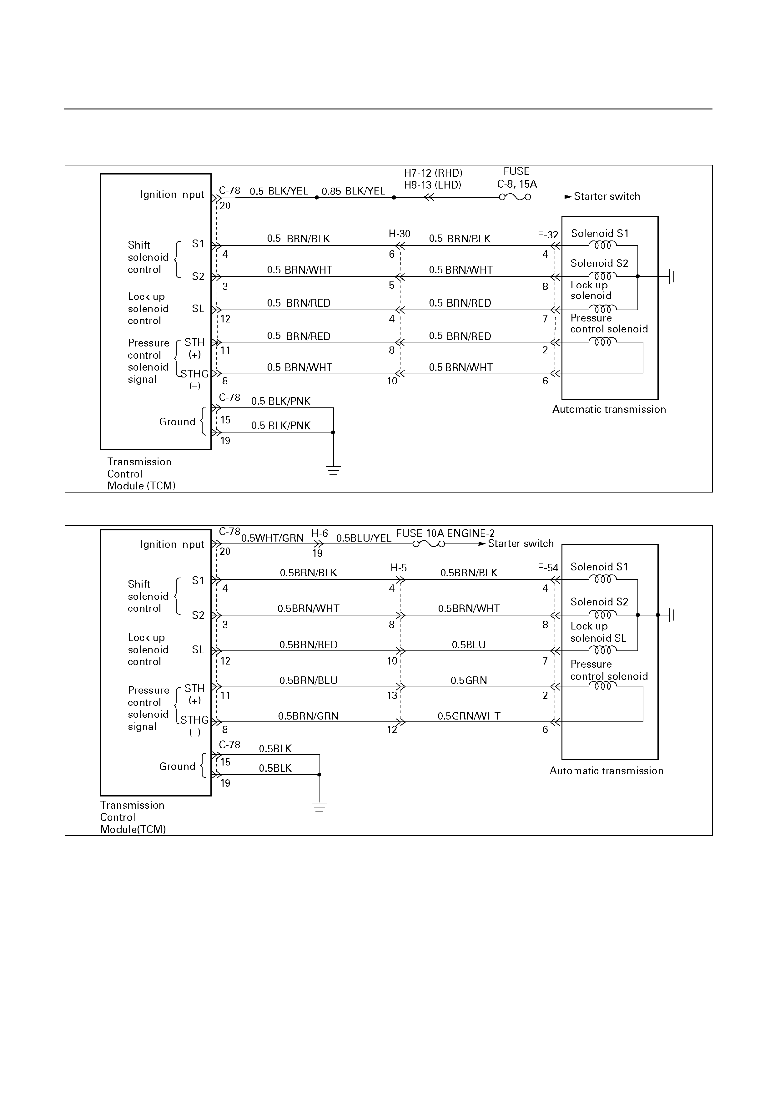
DTC P0758 (FLASHING CODE 32) SOLENOID 2 FAILURE (S2)
UBS
D07R200062
TFR/S
D07L200007

Circuit description:
The solenoid S2 changes the hydraulic route with the
signals from the TCM according to the vehicle speed
and the throttle opening to control shifting. When the
solenoid S1 or S2 fails, the hydraulic circuit is
mechanically operated as a backup.
Fail-safe control:
The TCM controls fail-safe by detecting S1, S2 shift
solenoid failure.
Failure detection:
GND SHORT detection
• When SHORT detection continues for 0.3 sec.
• When SHORT failure detection continues 8 times.
Open detection
• When OPEN detection continues for 0.5 sec.
• When OPEN failure detection continues 8 times.
Contents of control:
At failure detection
• Lock-up control inhibit
• Up hill and down hill control inhibit (For UBS)
• Squat control inhibit
• Changes solenoid output pattern as "The shift
theory at shift solenoid failure". (See DTC P0753)
At failure decision
• Executes following items in addition to above
control items at failure detection.
• Turns Solenoid power supply OFF
• Blinks "CHECK TRANS" lamp
• Stores the failure information in failure-memory
*Prohibits failure detection of S1, S2, SL, STH,
Selector position switch, and Oil temperature
sensor.
Conditions of turning "CHECK TRANS" off:
Turns "CHECK TRANS" lamp off after ignition is turned
ON→ OFF→ ON.
Reversion conditions from fail-safe:
At failure detection
When a normal judgment is obtained by rechecking
during shifting.
At failure decision
Recovers at the same time as the conditions of
turning “CHECK TRANS” lamp off are satisfied.
Test description:
The following numbers correspond to the step numbers
on the diagnostic chart.
1. With the key "ON", the voltage between the TCM
20 pin connector terminals (3) or (15 or 19) is 1V or
less.
4. When the driving wheels revolve with the 2nd
speed gear, the voltage is 8 to 16V.
3.6.8.11. The resistance of the solenoid is in the range
of 11 to 15Ω (at 20).
Diagnostic aids:
In case of faulty connection, open or shorted circuit to
the TCM 20 pin connector terminal (3), DTC P0758 is
displayed. A intermittent failure may be caused by a
poor connection, rubbed through wire insulation or a
wire broken inside the insulation.

DTC P0758 (FLASHING CODE 32) SOLENOID 2 FAILURE (S2)
Step Action Value(s) Yes No
1
1. With the engine "OFF", turn the ignition
"ON".
2. Connect a voltmeter between the TCM 20
pin connector terminal (3) and ground
terminal (15 or 19).
Is the voltage less than the specified value?
1 V Go to Step 2 Go to Step 3
2
1. Lift the driving wheels and support them.
2. Turn the ignition "ON", and the engine "ON".
Can the speed be changed normally by
acceleration is the "NORMAL" mode and the D
range?
Go to Step 4 Go to Step 8
3
1. Turn the ignition "OFF".
2. Disconnect the TCM 20 pin connector.
3. Measure the resistance between the TCM 20
pin connector terminal (3) and ground.
Is the resistance within the specified value?
11-15Ω (at 20°C)
12-16Ω (at 40°C)
Go to Step 5 Go to Step 6
4
At the 2nd speed gear.
Is the voltage between the TCM 20 pin connector
terminal (3) and ground terminal (15 or 19) within
the specified value?
8-16 V Go to Step 7 Go to Step 8
5
The TCM is faulty or the continuity of wiring
harness is intermittent.
Was a problem found and corrected?
Go to Step 13
6
Disconnect the A/T 8 pin connector.
Is the resistance between the solenoid S2
connector terminal (3) and ground within the
specified value?
11-15Ω (at 20°C)
12-16Ω (at 40°C)
Go to Step 9 Go to Step 10
7
1. Clear the TCM memory.
2. Make a running test.
Is DTC P0758 displayed by self-diagnosis?
Go to Step 5 The continuity
of wiring is
intermittent.
Refer to
"Diagnostic
aids".
8
1. Turn the ignition "OFF".
2. Disconnect the TCM 20 pin connector.
3. Measure the resistance between the TCM 20
pin connector terminal (3) and ground.
Is the resistance within the specified value?
11-15Ω (at 20°C)
12-16Ω (at 40°C)
Go to Step 5 Go to Step 11
9
Check the wiring harness between the TCM 20
pin connector terminal (3) and A/T 8 pin
connector terminal (8) for ground shorted.
Was a problem found and corrected?
Go to Step 13
10 Replace the solenoid S2.
Is the replacement complete?
Go to Step 13
11
1. Disconnect the A/T 8 pin connector.
2. Measure the resistance between the A/T 8
pin connector terminal (8) and ground.
Is the resistance within the specified value?
11-15Ω (at 20°C)
12-16Ω (at 40°C)
Go to Step 12 Go to Step 10

Step Action Value(s) Yes No
12
Check the wiring harness between the TCM 20
pin connector terminal (3) and A/T 8 pin
connector terminal (8) for open.
Was a problem found and corrected?
Go to Step 13
13
1. After the repair is complete, use the scan tool
to select "DTC", then "Clear Info" function.
2. Make a road running test for the vehicle.
3. Review the scan tool "DTC Info".
Has the last test failed or is the current DTC
displayed?
Begin the
diagnosis
again.
Go to Step 1
System OK
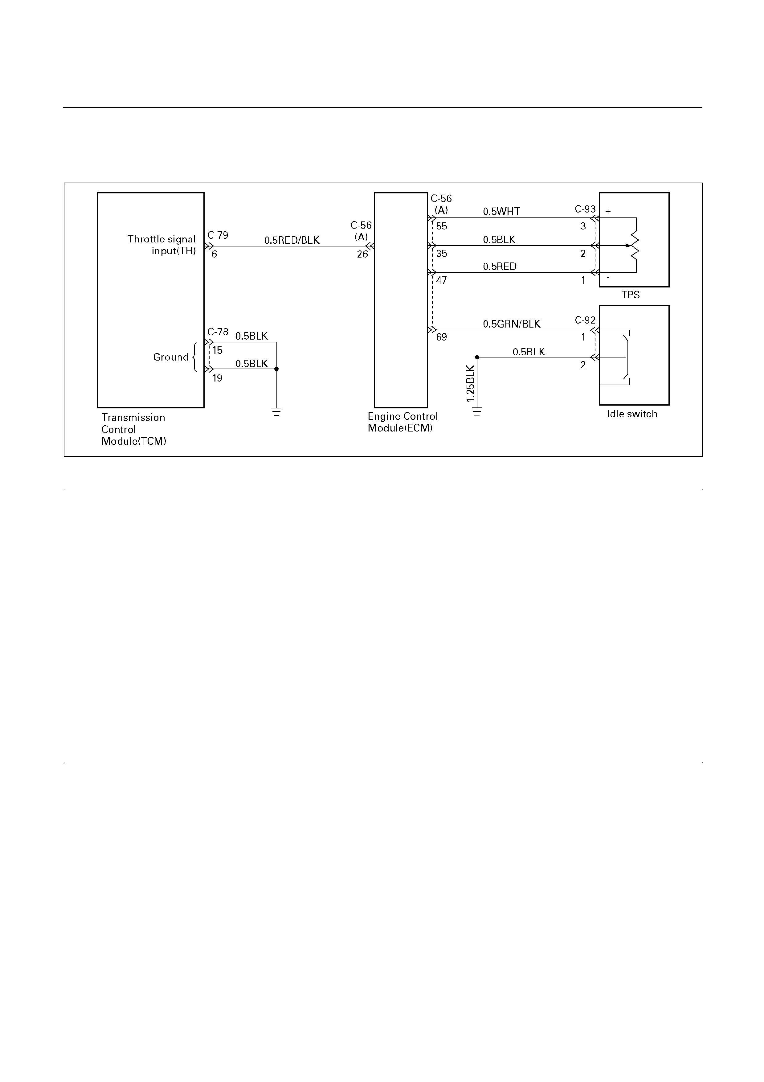
DTC P1120 (FLASHING CODE 22)
PWM THROTTLE SIGNAL FAILURE (TH) (For TFR/S)
TFR/S
Circuit description:
When the PWM signal of the engine throttle position
sensor located on the engine manifold (‘01TFR, For
Thailand) or accelerator pedal assembly (TFR/S) is
supplied to the TCM via the ECM, the TCM judges the
opening condition of the throttle
The shift point of th transmission is determined by this
PWM throttle signal.
Fail-safe control:
The TCM controls fail-safe by detecting PWM throttle
signal (TH) failue.
Failure detection:
When the throttle input duty ratio is detected less
than 1%or more than 99% for 2.0 seconds.
Contents of control:
At failure detection
Throttle opening for line pressure control = 100%
Throttle opening for shift control = 0%
Lock-up control inhibit
Squat control inhibit
Flash the 'CHECK TRANS' lamp
Conditions of turning “CHECK TRANS” lamp
off:
Turns “CHECK TRANS” lamp off when judged 0km/h
by output revolution sensor after throttle signal input
duty ratio is detected at more than 1% and less than
99%.
(however, uses 0km/h judgment by back-up vehicle
speed at output revolution sensor failure)
Conditions to exit from fail-safe:
At failure detection
• Immediately recovers when the throttle input duty
ratio is detected more than 1% and less than 99%.
At failure detection
• Recovers at the same time as the conditions of
turning “CHECK TRANS” lamp off are satisfied.
Test description:
The following numbers correspond to the step numbers
on the diagnostic chart.
1. Check that the throttle input voltage is 4.4 to 4.6V.
2. At this test, check that as the throttle opens, the
voltage goes up and that the voltage reached 0.4 to
0.6V at the full open status.
6. Check the power supply voltage (4.99-5.01V) of the
each throttle position sensors.
Diagnostic aids:
An intermittent may be caused by a poor connection,
rubbed through wire insulation or a wire broken inside
the insulation. Inspect related harness connector for
backed out terminals, improper mating, broken locks,
improperly formed or damaged terminals, poor terminal
to wire connection and damaged harness.

DTC P1120 (FLASHING CODE 22)
PWM THROTTLE SIGNAL FAILURE (TH) (For TFR/S)
Step Action Value(s) Yes No
1
1. Connect a analog voltmeter between the
TCM 28 pin connector terminal (6) and TCM
20 pin connector terminal (15 or 19).
2. Turn the ignition "ON".
Is the voltage within the specified value?
4.4-4.6 V
*
Go to Step 2 Go to Step 3
2
Open the throttle fully.
Is the voltage within the specified value?
0.4-0.6 V
*
The problem is
intermittent.
Refer to
"Diagnostic
aids".
Go to Step 3
3
1. Turn the ignition "ON".
2. Measure the voltage between the ECM 81
pin connector terminal (26) and ground
terminal (47) (TFR/S), or ECM 32 pin
connector terminal (14) and ground terminal
(33 or 49) (
Is the voltage within the specified value?
4.4-4.6 V
*
Go to Step 4 Go to Step 6
4 Open the throttle fully.
Is the voltage within the specified value?
0.4-0.6 V
*
Go to Step 5 Go to Step 6
5
Check the wiring harness between the TCM 28
pin connector terminal (6) and ECM 81 pin
connector terminal (26) (TFR/S), or ECM 32 pin
connector terminal (14) ('01 TFR, for Thailand).
Or TCM is faulty.
Was a problem found and corrected?
Go to Step 9
6
1. Disconnect the TPS connector.
2. Connect a voltmeter between the TPS
connector terminal (C93-3) and (C93-1)
(TFR/S), or TPS connector terminal (B17-2)
and (B17-1), or (B18-3) and (B18-2) ('01
TFR, for Thailand).
Is the voltage within the specified value?
4.99-5.01 V Go to Step 7 Go to Step 8
7
Check the TPS connectors. If OK, replace the
TPS.
Is the replacement complete?
Go to Step 9
8
Check the wiring harness between the TPS and
ECM.
If OK, replace the ECM.
Is the replacement complete?
Go to Step 9
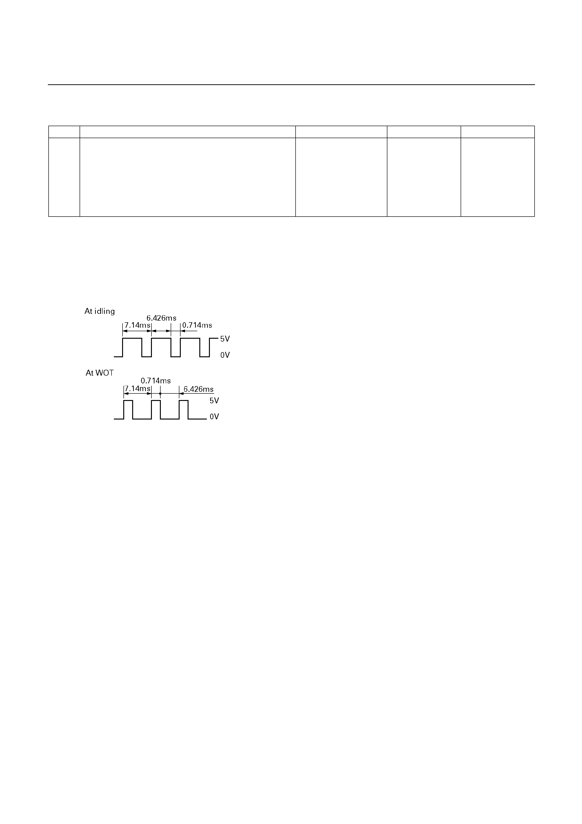
Step Action Value(s) Yes No
9
1. After the repair is complete, use the scan tool
to select "DTC", then "Clear Info" function.
2. Make a road running test for the vehicle.
3. Review the scan tool "DTC Info".
Has the last test failed or is the current DTC
displayed?
Begin the
diagnosis
again.
Go to Step 1
System OK
*Reference (Oscilloscope waveform)
(TFR/S)
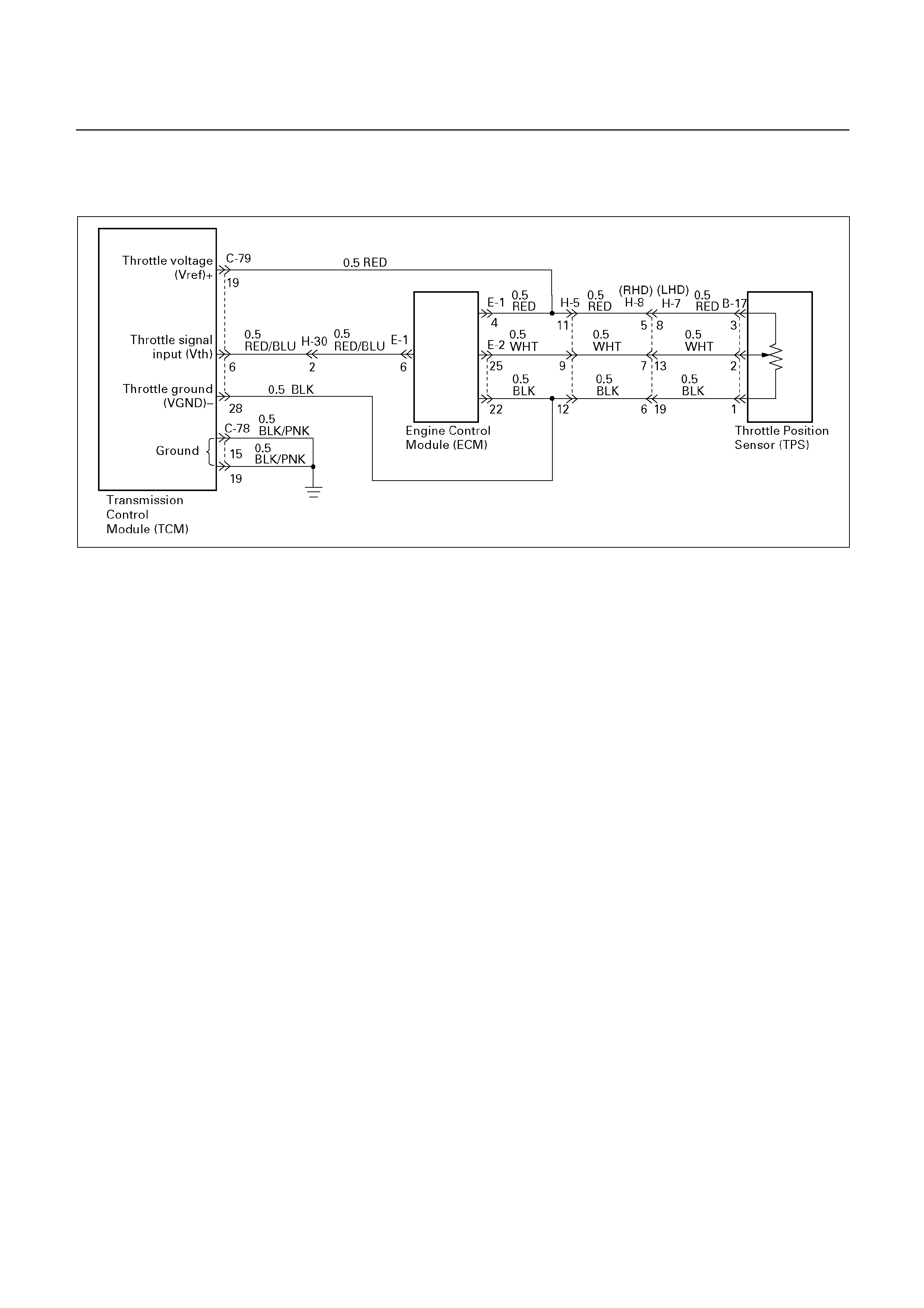
DTC P1121 (FLASHING CODE 23)
ANALOG THROTTLE SIGNAL FAILURE (VREF, VGND)(For UBS)
D07R200063
Circuit description:
When the signal of the engine throttle position sensor
located on the accelerator pedal is supplied to the
transmission TCM, the TCM judges the opening
condition of the throttle.
The shift point of the transmission is determined by this
opening condition of the throttle.
Fail-safe control:
The TCM controls fail-safe by detecting analog throttle
signal (VREF, VGND) failure.
Failure detection:
• When the Vref input voltage is detected more than
5.55V or less than 4.45V.
• When the Vgnd input voltage is detected more than
0.40V or less than -0.40V.
• When the failure criteria is continuously for 1.0 sec.
Contents of control:
At failure detection
• Judges throttle opening of linear sensor (Vth) as
Vref:5V, Vgnd:0V
• Throttle learning control inhibit
• Up hill and down hill control inhibit
At failure decision
Executes following items in addition to above
control items at failure detection.
• Stores the failure information in failure-memory
Conditions of turning “CHECK TRANS” lamp
off:
None
Reversion conditions from fail-safe:
At failure detection
When the Vref input voltage is detected less than 5.55
V and more than 4.45 V.
When the Vgnd input voltage is detected less than 0.40
V and more than -0.40 V.
At failure decision
• Recovers when judged 0km/h by output revolution
sensor after the Vref input voltage is detected less
than 5.55V and more than 4.45V.
(however, uses 0 km/h judgment by back-up
vehicle speed at output revolution failure)
• Recovers when judged 0km/h by output revolution
sensor after the Vgnd input voltage is detected less
than 0.40V and more than -0.40V.
(however, uses 0 km/h judgment by back-up
vehicle speed at output revolution failure)
Test description:
The following numbers correspond to the step numbers
on the diagnostic chart.
1. Check the power supply voltage (4.75-5.25V) of
throttle position sensor.
Diagnostic aids:
An intermittent may be caused by a poor connection,
rubbed through wire insulation or a wire broken inside
the insulation. Inspect related harness connector for
backed out terminals, improper mating, broken locks,
improperly formed or damaged terminals, poor terminal
to wire connection and damaged harness.

DTC P1121 (FLASHING CODE 23)
ANALOG THROTTLE SIGNAL FAILURE (VREF, VGND)(For UBS)
Step Action Value(s) Yes No
1
1. With the engine "OFF", turn the ignition
"ON".
2. Connect a voltmeter between the TCM 28
pin connector terminal (19) and (28).
Is the voltage within the specified value?
4.75-5.25 V The problem is
intermittent.
Refer to
"Diagnostic
aids".
Go to Step 2
2
Connect a voltmeter between the ECM 32 pin
connector terminal (E1-4) and (E2-22).
Is the voltage within the specified value?
4.75-5.25 V Go to Step 3 Go to Step 4
3
Check the wiring harness between the TCM and
ECM.
Was a problem found and corrected?
Go to Step 5
4
Check the ECM 32 pin connectors. If OK,
replace the ECM.
Is the replacement complete?
Go to Step 5
5
1. After the repair is complete, use the scan tool
to select "DTC", then "Clear Info" function.
2. Make a road running test for the vehicle.
3. Review the scan tool "DTC Info".
Has the last test failed or is the current DTC
displayed?
Begin in the
diagnosis
again. Go to
Step 1
System OK
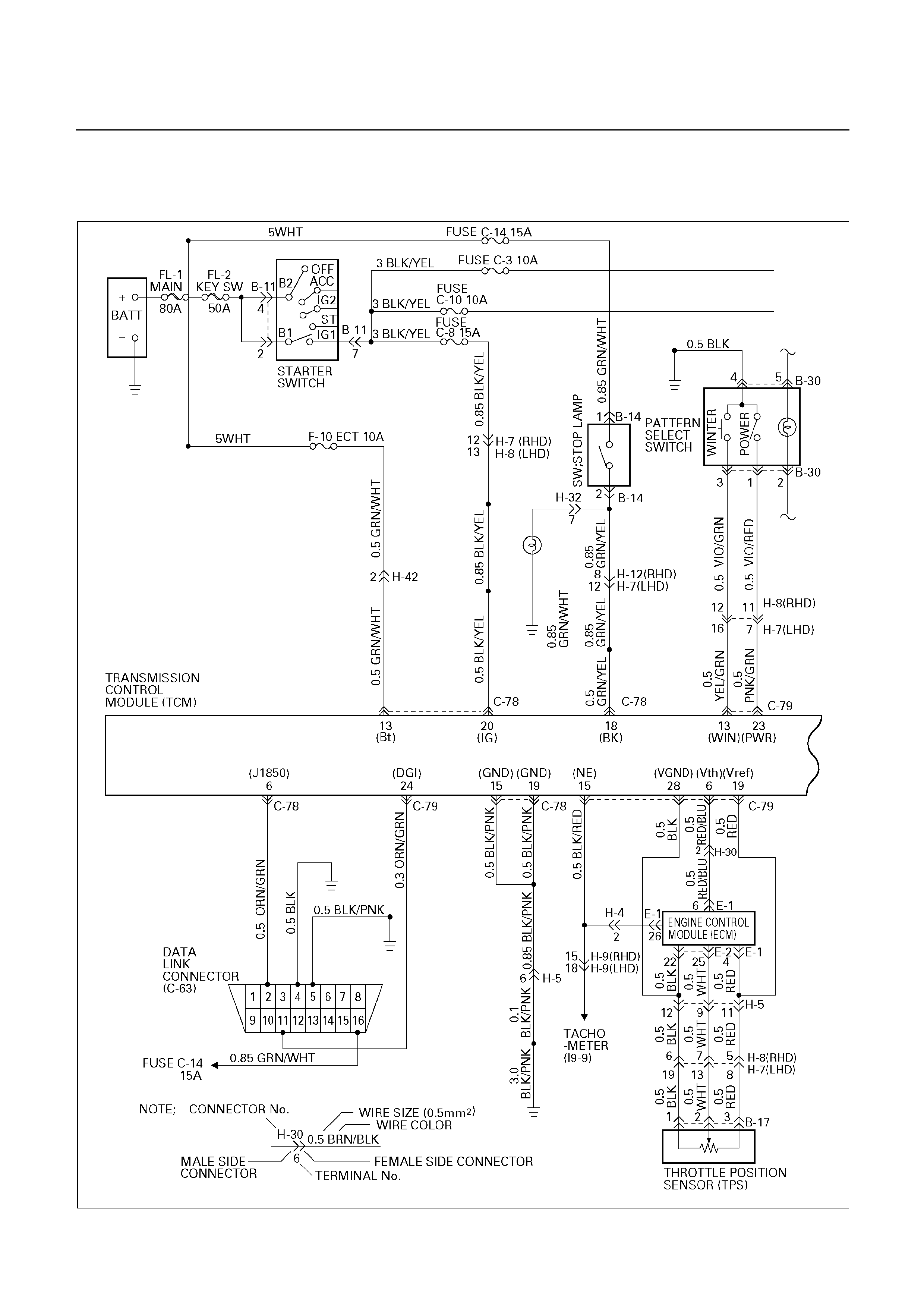
WIRING DIAGRAM
UBS
D07R200064
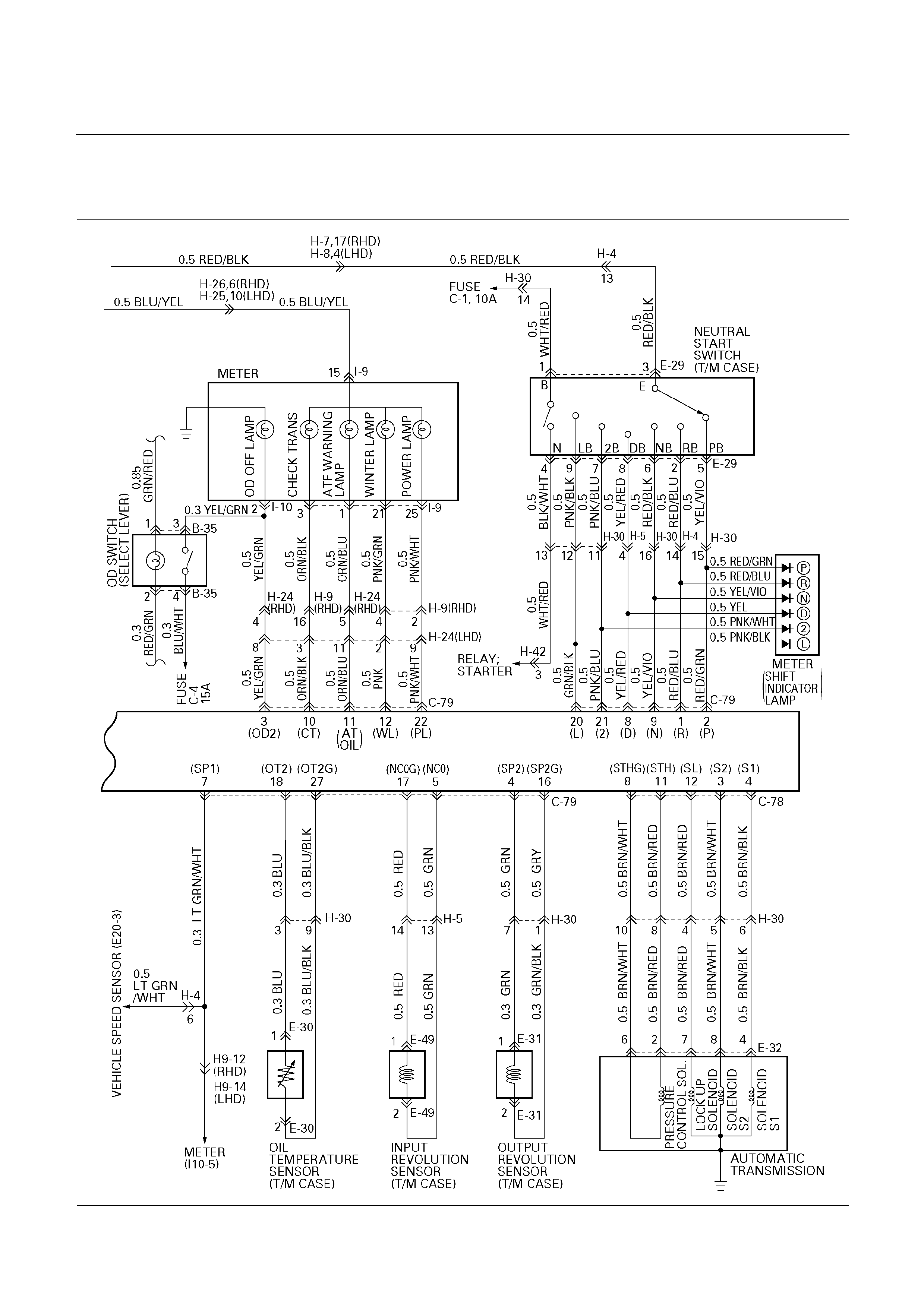
UBS
D07R200065
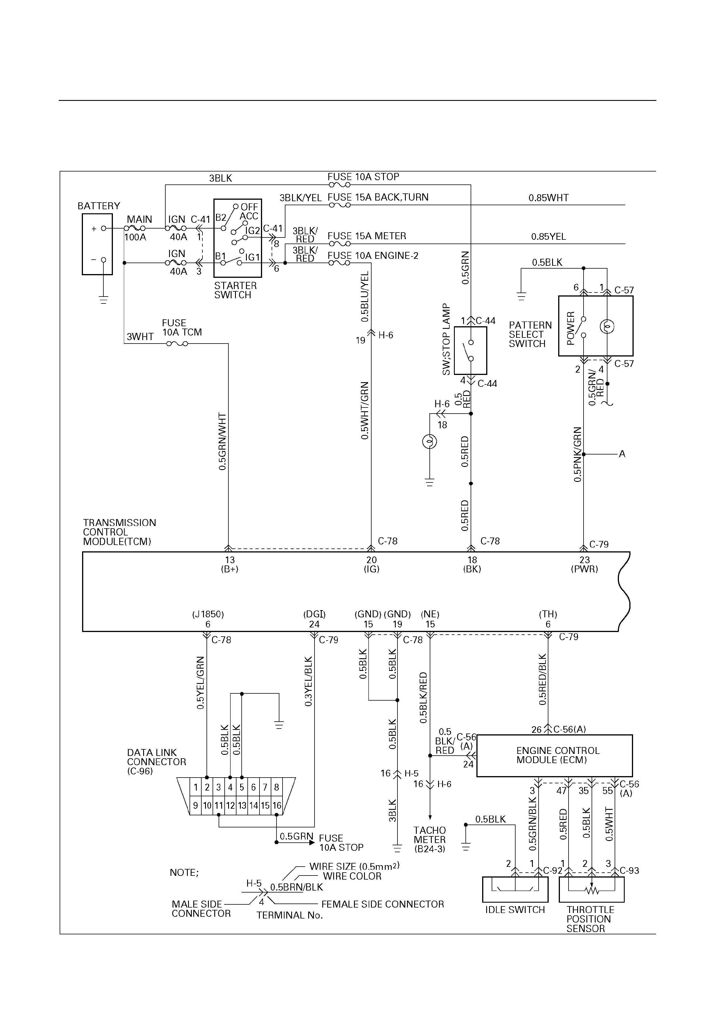
TFR/S
D07L200009
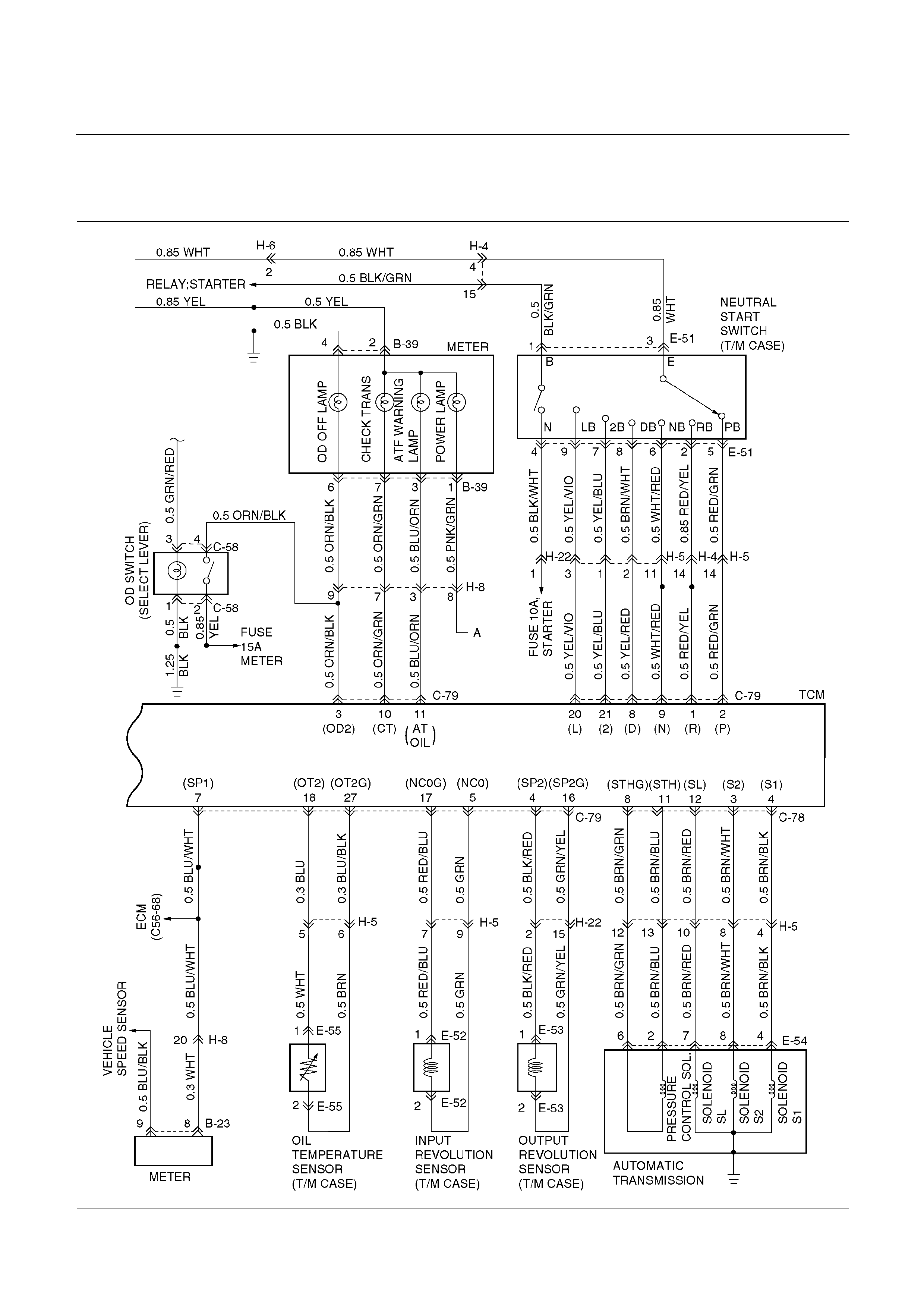
TFR/S
D07L200010
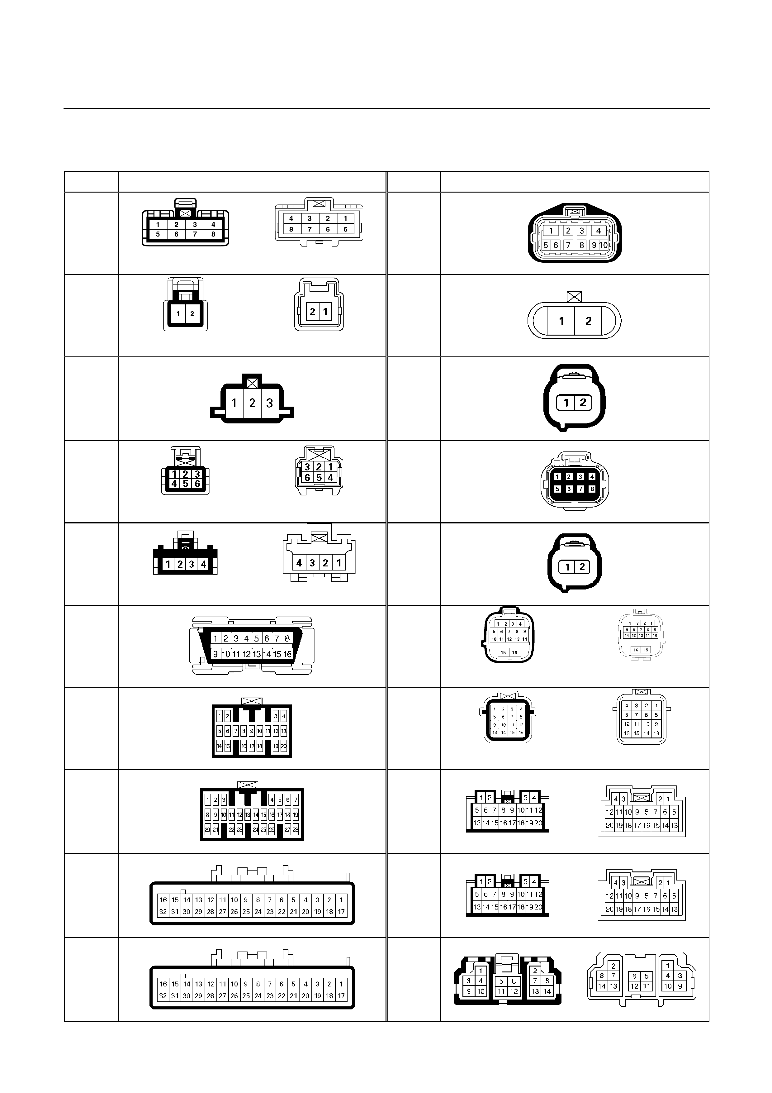
CONNECTOR LIST
UBS (For General Export)
No. Connector face No. Connector face
B-11
(WHITE)
E-29
B-14
(BLACK)
E-30
B-17
E-31
B-30
(WHITE)
E-32
B-35
(WHITE)
E-49
C-63
H-4
(BLACK)
C-78
H-5
(GREEN)
C-79
H-7
(RHD)
E-1
H-7
(LHD)
E-2
H-8
(RHD)
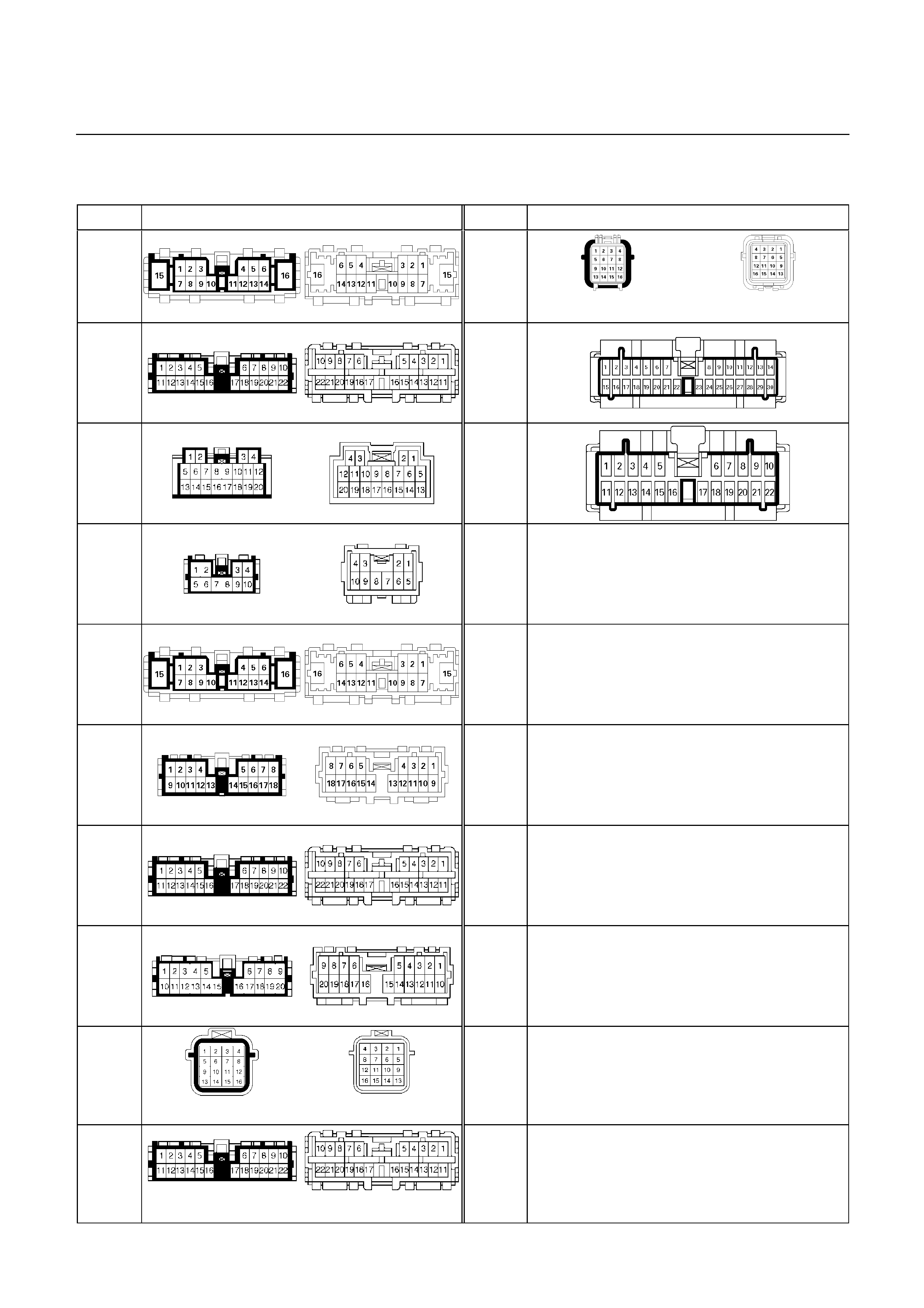
UBS
No. Connector face No. Connector face
H-8
(LHD)
H-42
(BLACK)
H-9
(RHD)
I-9
H-9
(LHD)
I-10
H-12
(RHD)
H-24
(RHD)
H-24
(LHD)
H-25
(LHD)
H-26
(RHD)
H-30
(NATURAL)
H-32
(BLACK)
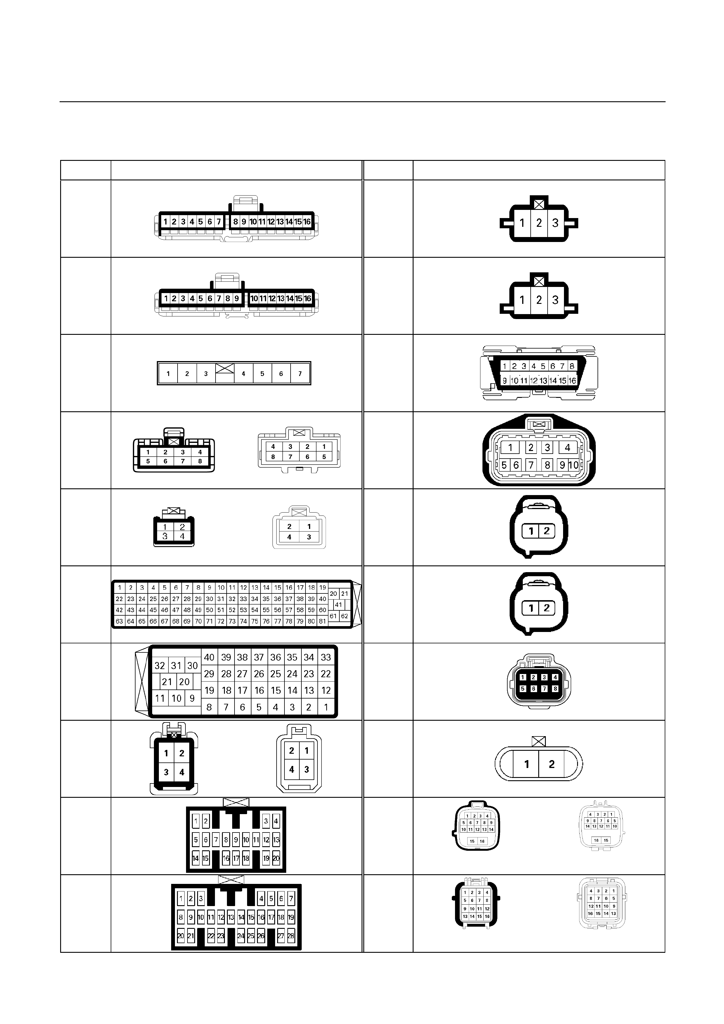
TFR/S
No. Connector face No. Connector face
B-23
C-92
B-24
C-93
B-39
C-96
C-41
E-51
C-44
E-52
C-56
E-53
C-57
E-54
C-58
E-55
C-78
H-4
(BLACK)
C-79
H-5
(BLACK)
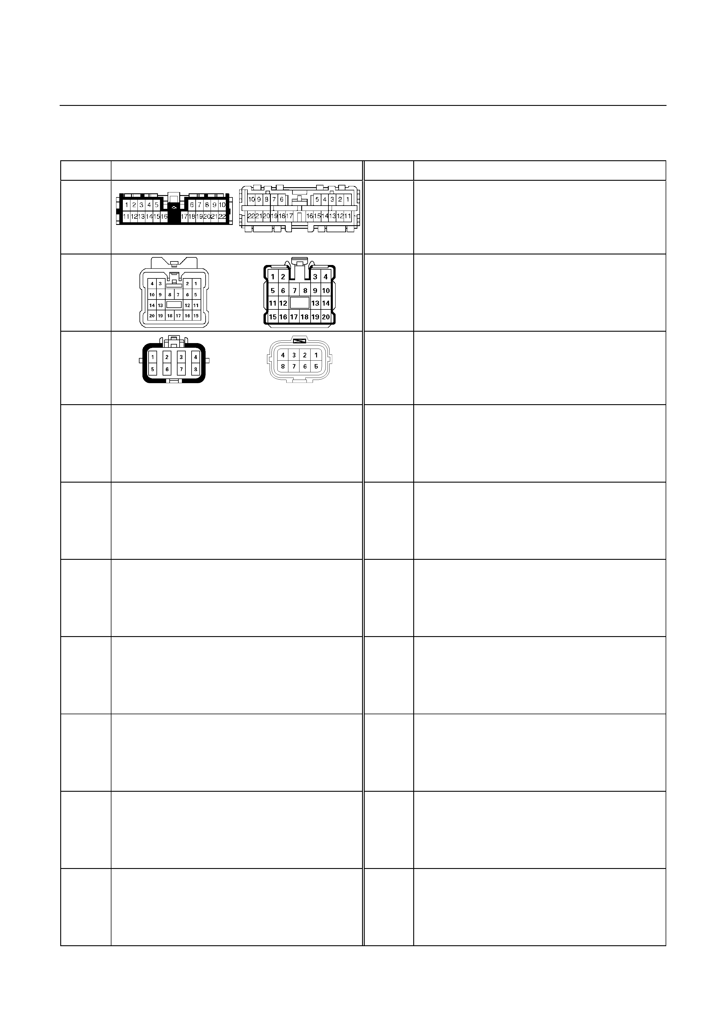
TFR/S
No. Connector face No. Connector face
H-6
(WHITE)
H-8
H-22
(GRAY)
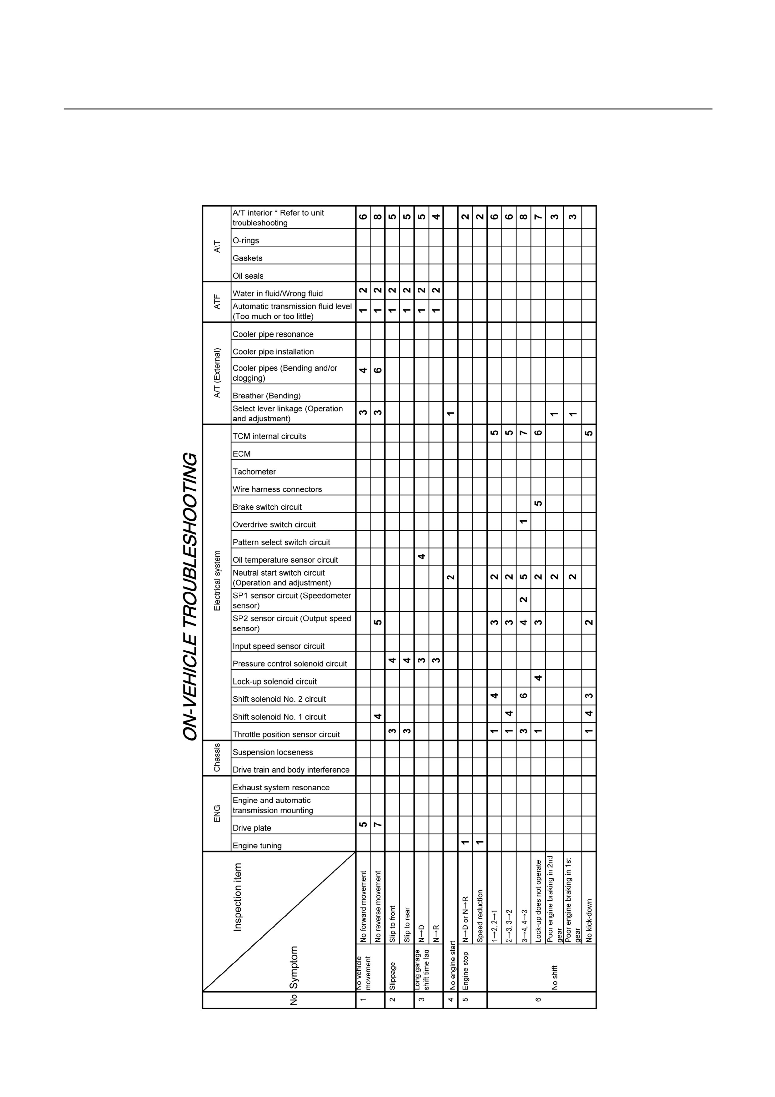
TROUBLESHOOTING CHART
Number are arranged in order of probability.
Parform inspections starting with number one and working up.
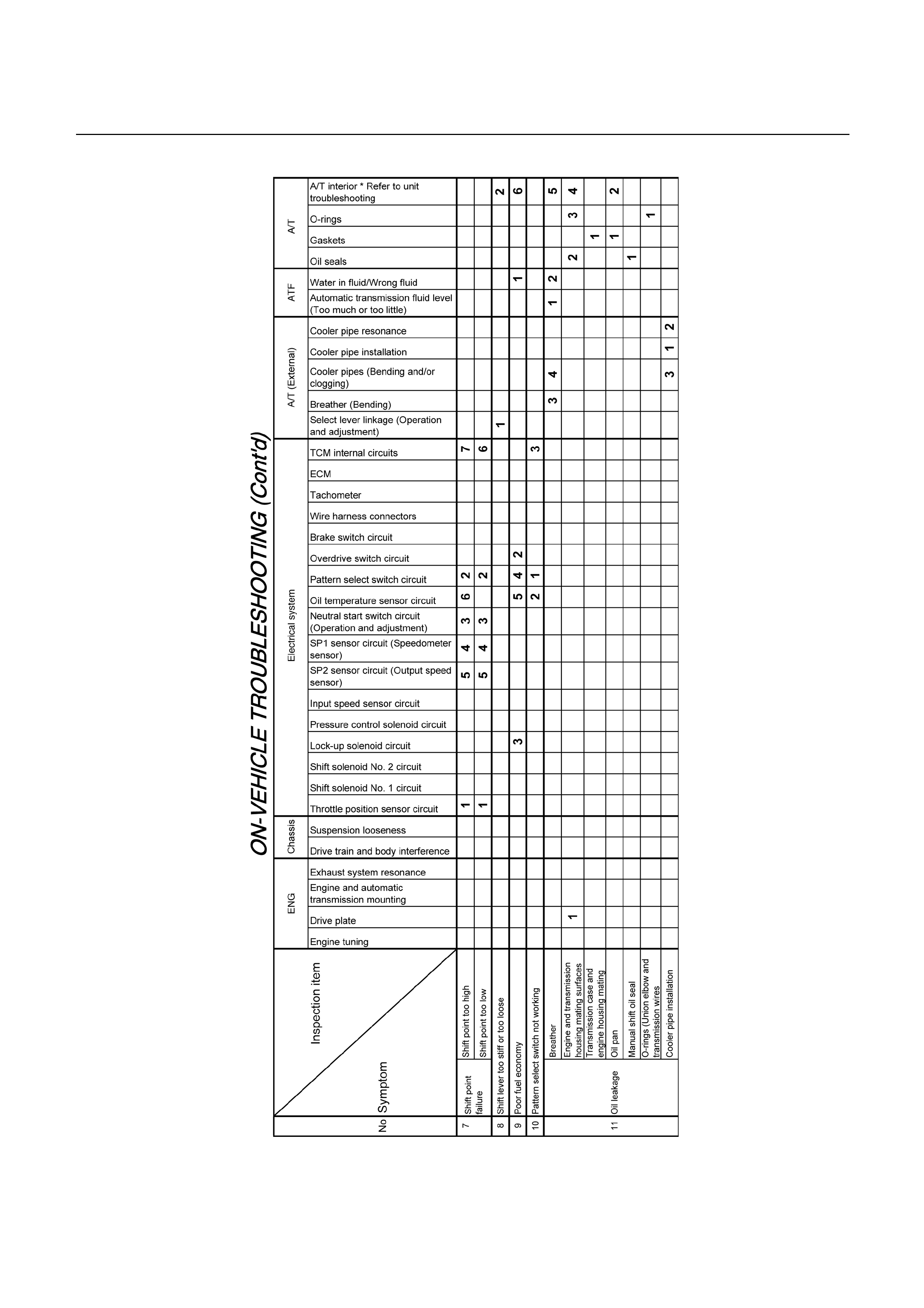
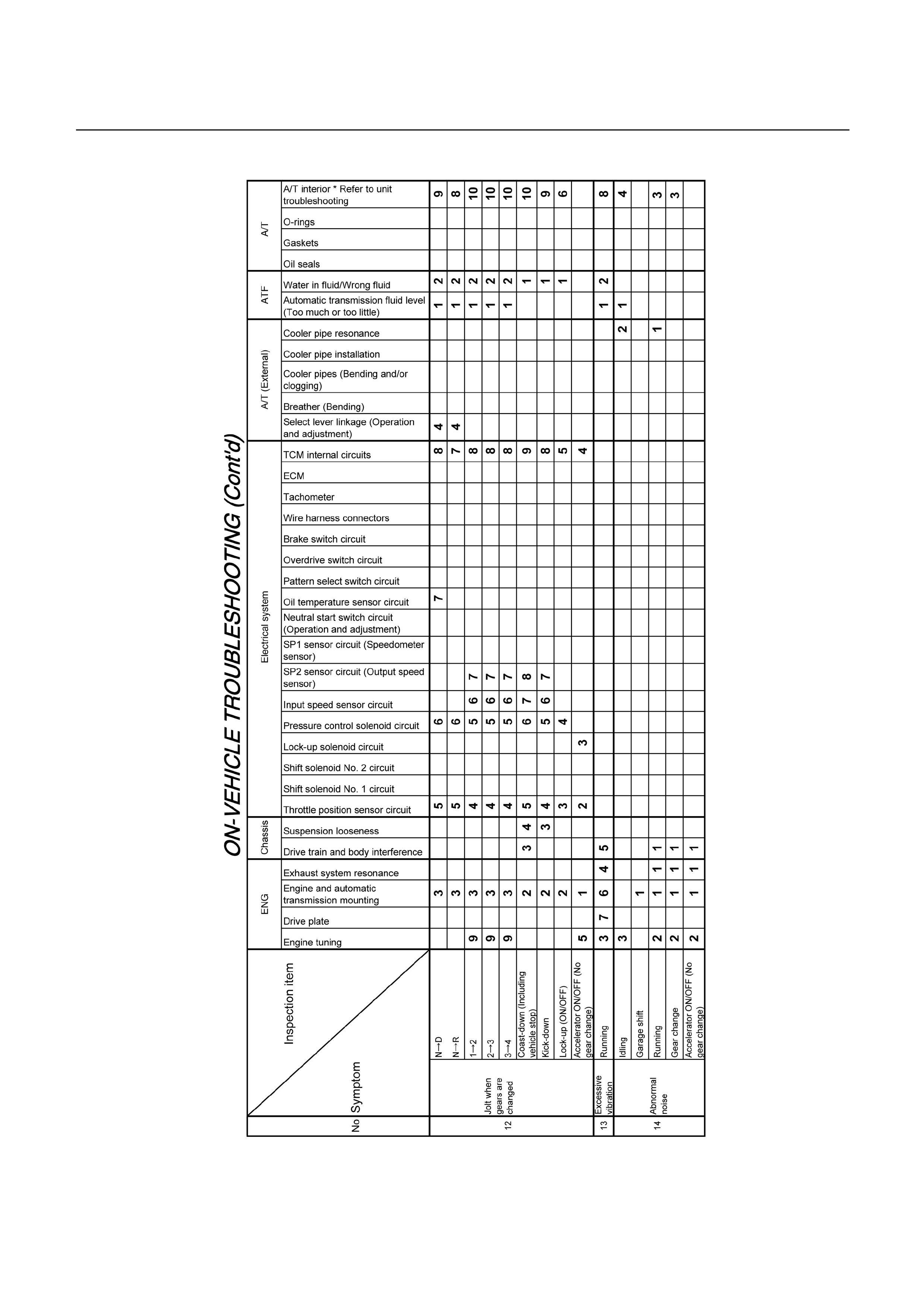
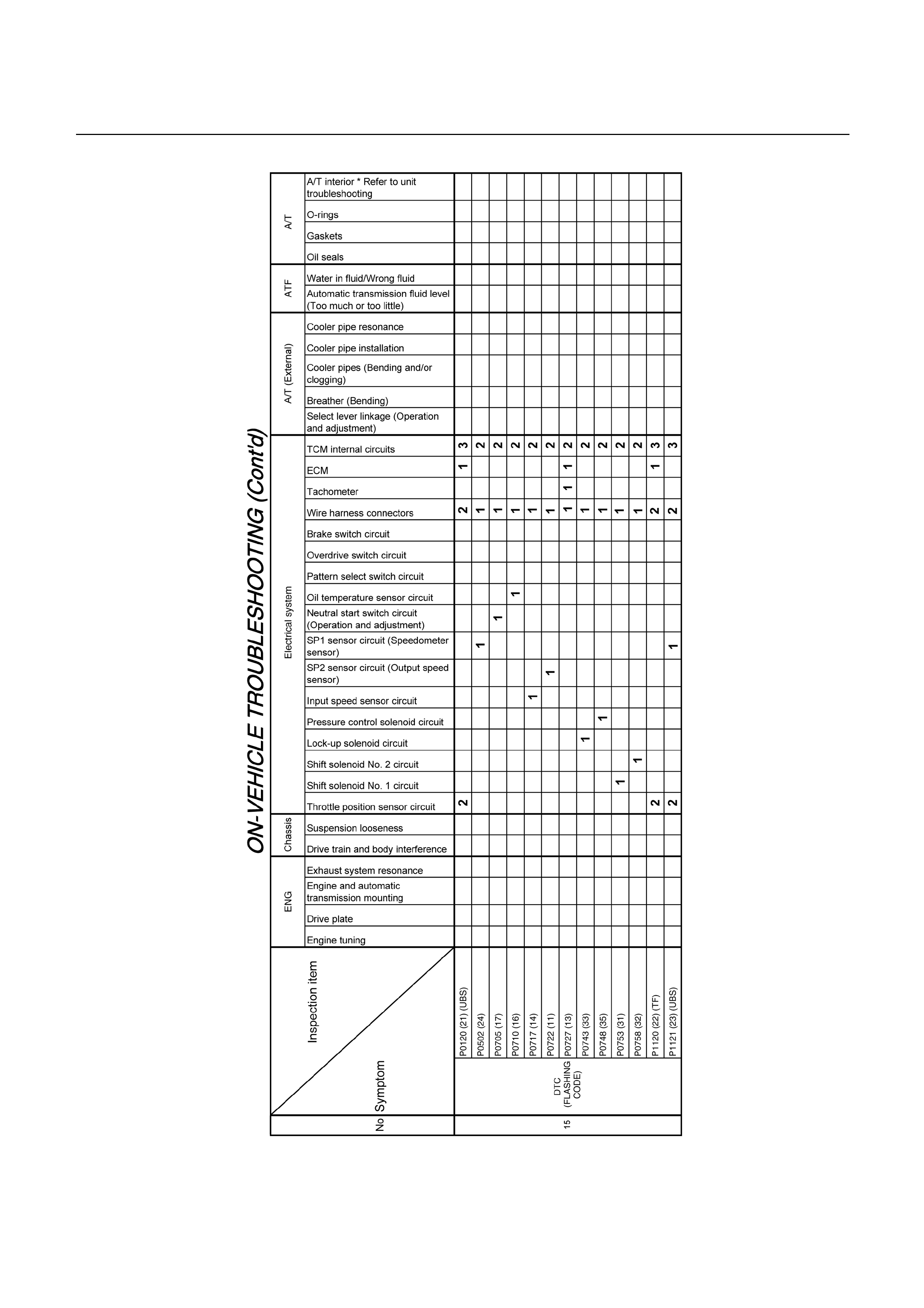
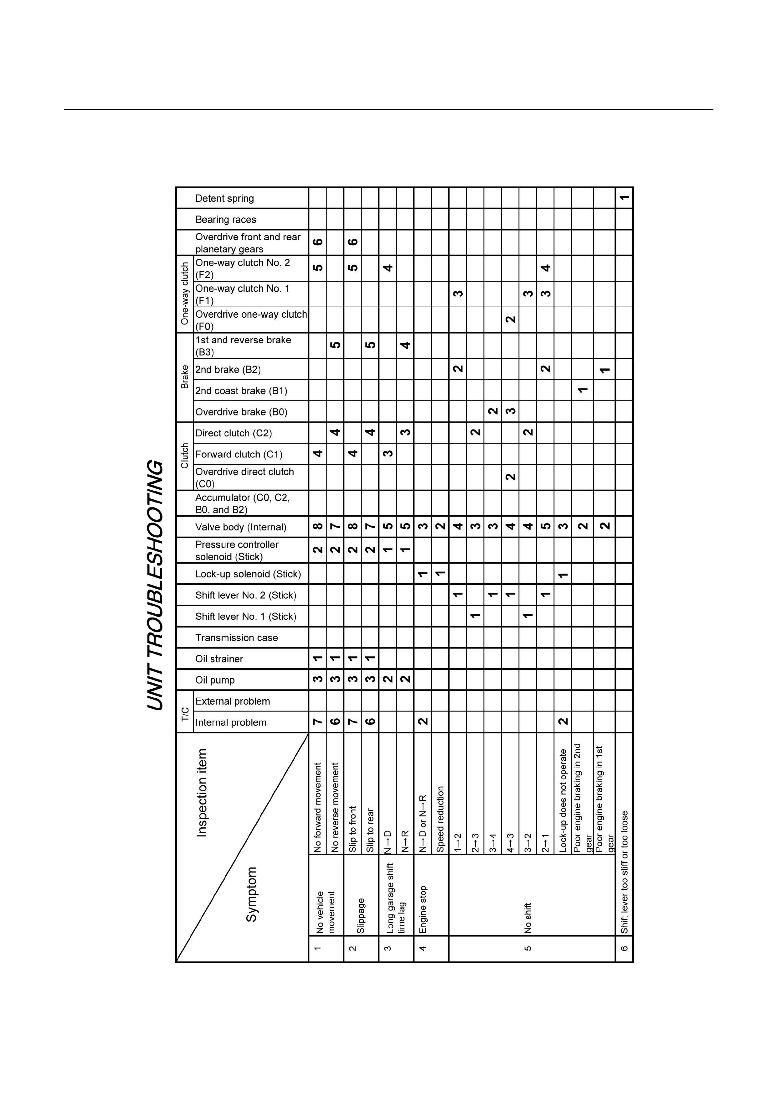
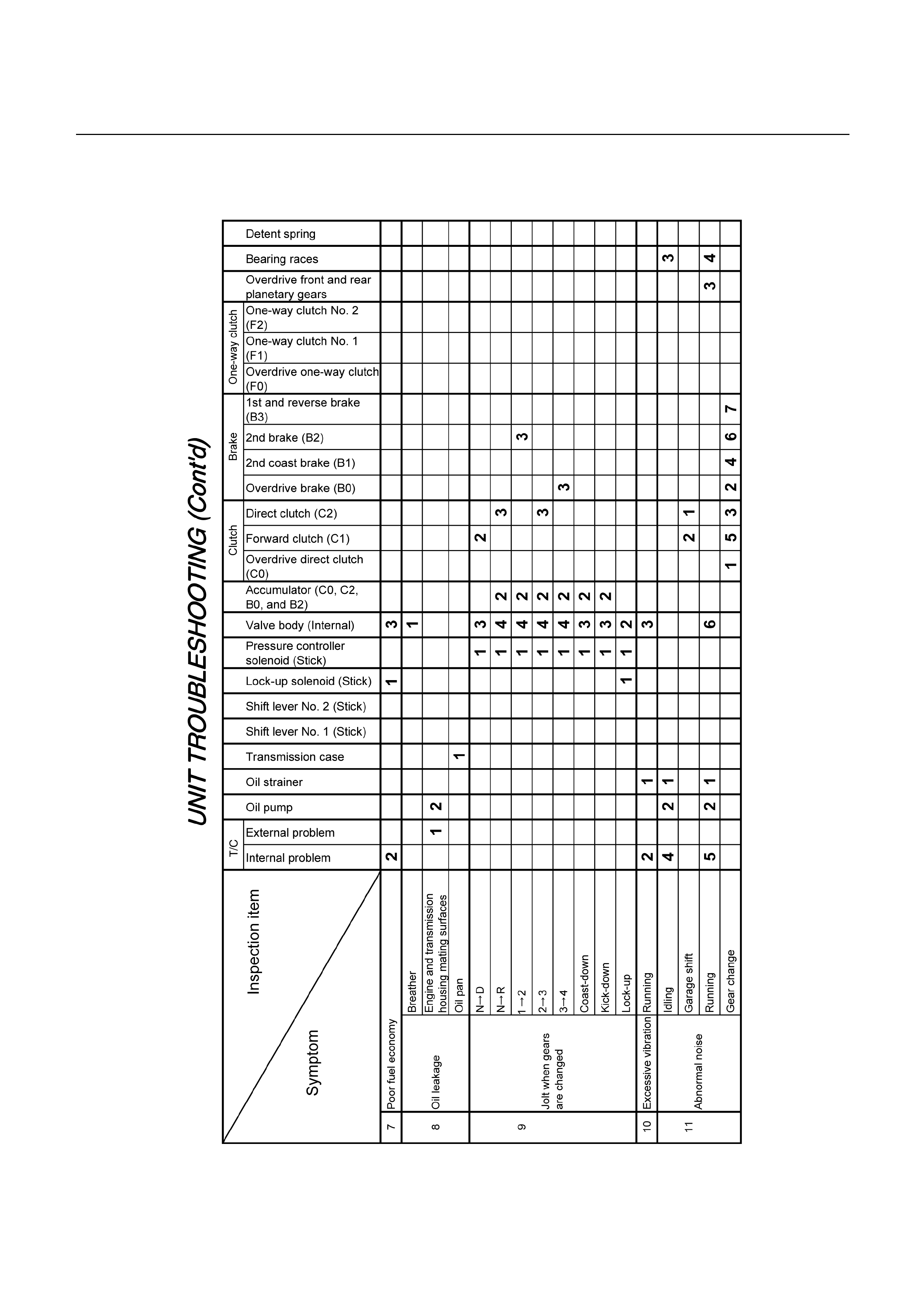
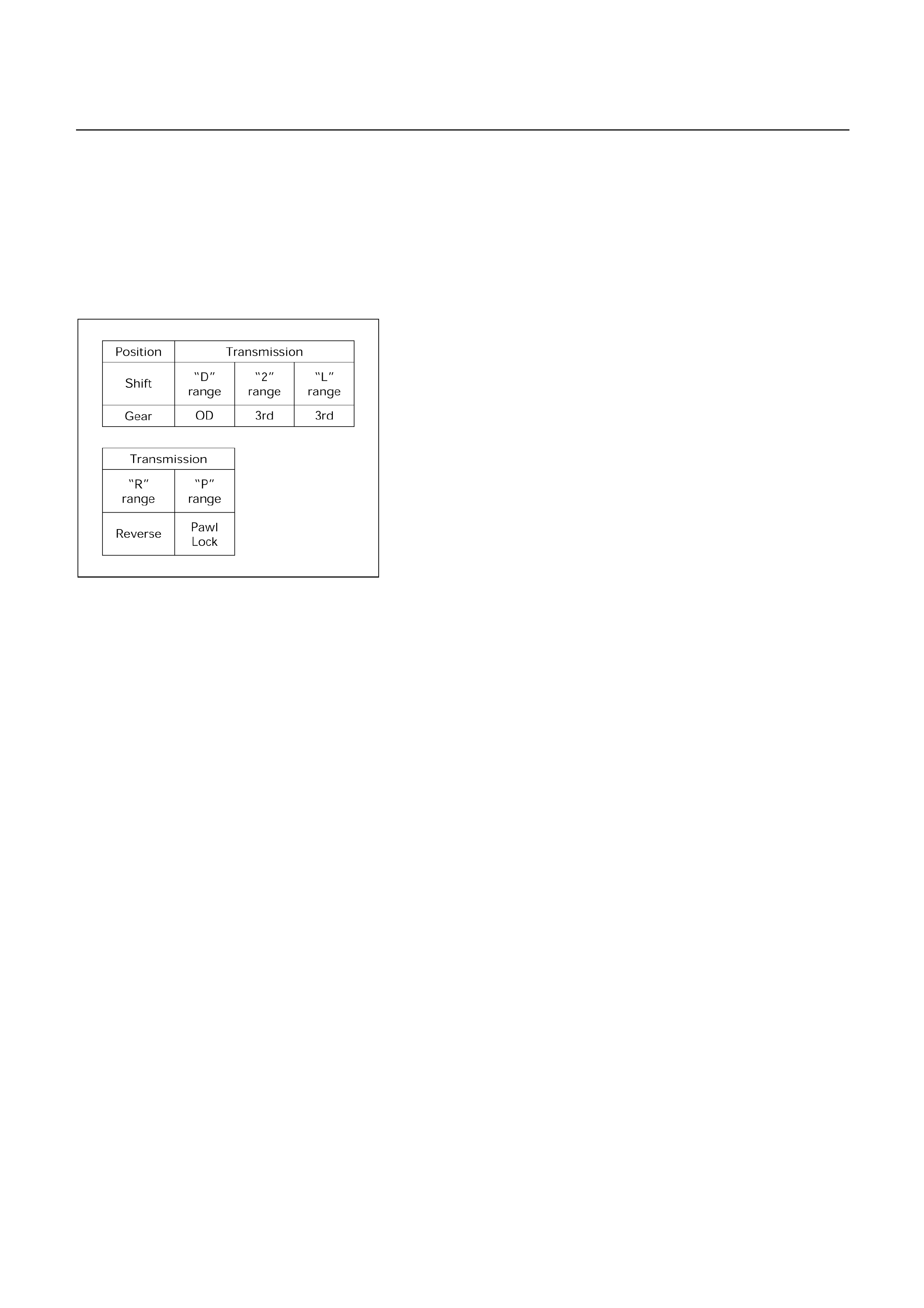
MANUAL SHIFTING TEST
NOTE:
With this test, it can be determined whether the trouble
lies within the electrical circuit or is a mechanical
problem in the transmission.
1. Disconnect TCM connector
With the engine OFF, disconnect the TCM connector.
F07RY00024
2. Inspect manual driving operation
Check that the shift and gear positions correspond with
the table.
If the “L”, “2” and “D” range gear positions are difficult to
distinguish, do perform the following road test.
While driving, shift through the “L”, “2” and “D” renges.
Check that the gear change corresponds to the gea
r
position.
If any abnormality is found in the above test, do perform
the stall, time lag or gear change tests.
3. Connect TCM connector
With the engine off, connect the TCM connector.
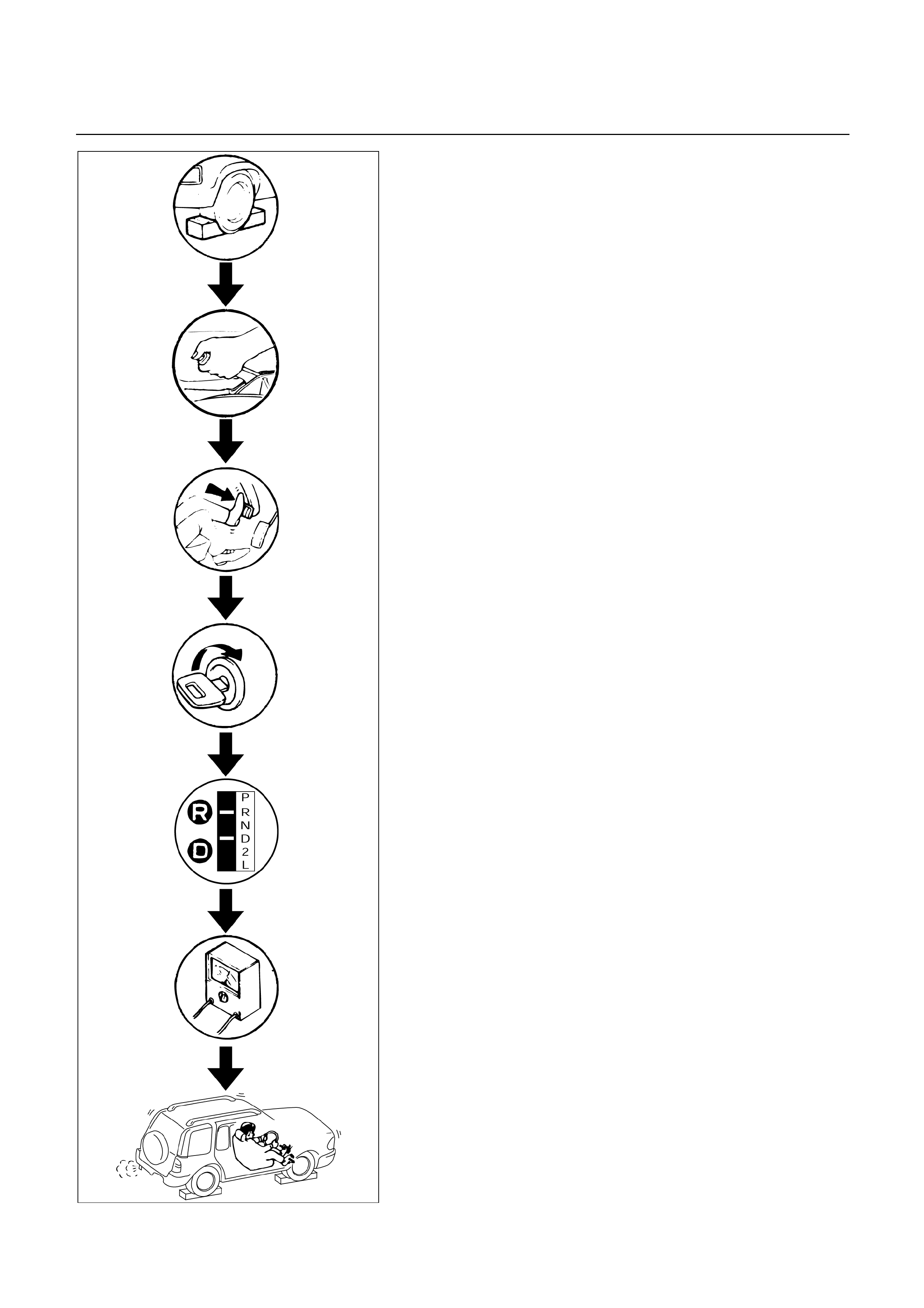
F07RY00002
STALL TEST
The object of this test is to check the overall performance
of the transmission and engine by measuring the maximum
engine speeds at the “D” and “R” ranges.
NOTE:
(1) Perform the test at normal operation fluid
temperature (50 – 80º
ºº
ºC or 122-176 º
ºº
ºF).
(2) Do not continuously run this test longer than 5
seconds.
MEASURE STALL SPEED
1. Chock all four wheels.
2. Connect an engine tachometer.
3. Fully apply the parking brake.
4. Step down strongly on the brake pedal with your left
foot.
5. Start the engine.
6. Shift into the “D” range. Step all the way down on the
accelerator pedal with your right foot. Quickly read the
highest engine rpm.
Stall speed: 2450 150 rpm (UBS)
: 2300 150 rpm (TFR/S)
7. Perform the same test in the “R” range.
EVALUATION
1. If the engine speed is the same for both ranges but
lower than the specified value:
Engine output is insufficient.
Stator one-way clutch is not operating properly.
NOTE:
If more than 600 rpm below the specified value, the
torque converter could be faulty.
2. If the stall speed is “D” range is higher than specified:
Line pressure too low
Forward clutch slipping
No.2 one-way clutch not operating properly
3. If the stall speed in “R” range is higher than specified:
Line pressure too low
Direct clutch slipping
No.3 brake slipping
4. If the stall speed in the “R” and “D” ranges are highe
r
than specified:
Line pressure too low
Improper fluid level
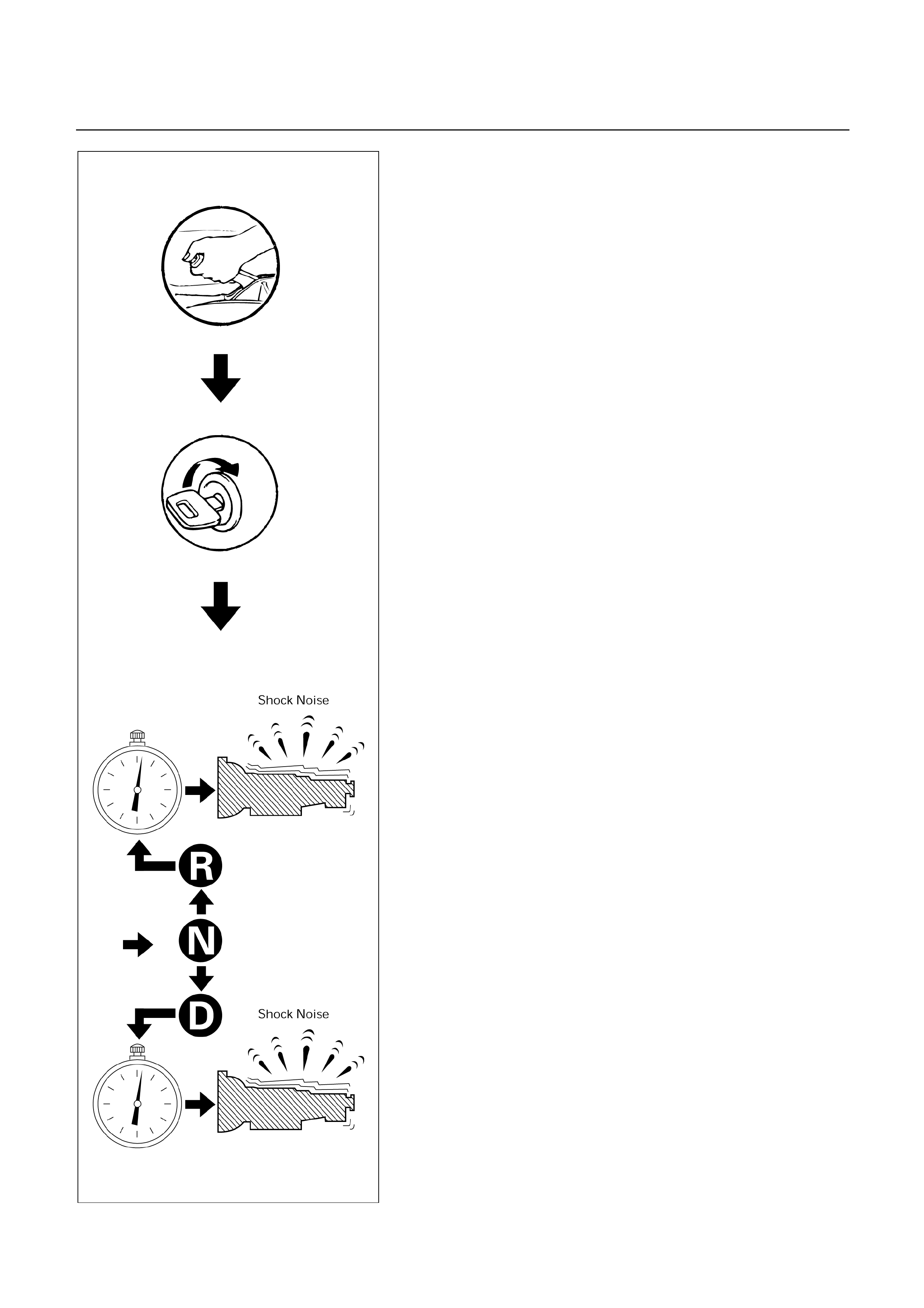
F07RY00003
TIME LAG TEST
If the shift lever is shifted while the engine is idling, there
will be a certain time elapse or lag before the shock can be
felt. This is used for checking the condition of the forward
clutch, direct clutch, No.3 brake, and No.2 one-way clutch.
NOTE:
(1) Perform the test at normal operation fluid
temperature (50 – 80º
ºº
ºC or 122 – 176º
ºº
ºF)
(2) Be sure to allow one minute interval between
tests.
(3) Make three measurements and take the average
value.
MEASURE TIME LAG
1. Fully apply the parking brake.
2. Start the engine.
Check idling speed (A/C OFF).
3. Shift the shift lever from “N” to “D” range. Using a stop
watch, measure the time it takes from sihfting the leve
r
until the shock is felt.
Time lag: Less than 0.7 seconds
4. In same manner, measure the time lag for “N” “R”.
Time lag: Less than 1.2 seconds
EVALUATION
1. If “N” “D” time lag is longer than specified:
Line pressure too low
Forward clutch malfunction
No.2 one-way clutch not operating properly
2. If “N” “R” time lag is longer than specified:
Line pressure too low
Direct clutch malfunction
No.3 brake malfunction
3. If both time lag is longer than specified:
Line pressure too low
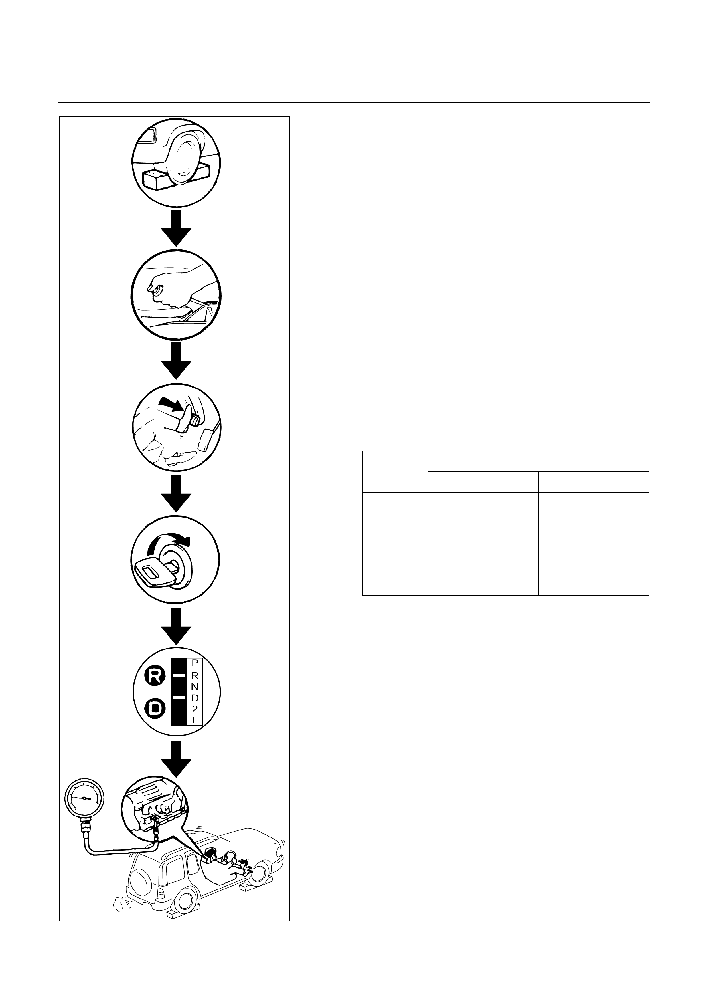
HYDRAULIC TEST
PREPARATION
1. Warm up the transmission fluid.
2. Remove the transmission case test plug and mount the
hydraulic pressure gauge.
Oil pressure gauge: 5-8840-0093-0
NOTE:
Perform the test at normal operation fluid temperature
(50 – 80º
ºº
ºC or 122 – 176º
ºº
ºF).
MEASURE LINE PRESSURE
1. Fully apply the parking brake and chock the fou
r
wheels.
2. Start the engine and check idling rpm.
3. Shift into “D” range, step down strongly on the brake
pedal with your left foot and, while manipulating the
accelerator pedal with the right foot, measure the line
pressures at the engine speeds specified in the table.
4. In the same manner, perform the test in “R” range.
Line pressure kPa (kg/cm2/psi)
Engine
speed “D” range “R” range
Idling
358 – 417
(3.6 – 4.3/
51 – 61)
588 – 686
(6.0 – 7.0/
85 – 100)
Stall
1,176 – 1,323
(12.0 – 13.5/
171 – 192)
1,607 – 1,940
(16.4 – 19.8/
233 – 282)
F07RY00004
EVALUATION
1. If the measured values at all ranges are higher than
specified:
Pressure control solenoid defective
Primary regulator valve defective
2. If the measured values at all ranges are lower than
specified:
Primary regulator valve defective
Oil pump defective
Pressure control solenoid defective
3. If pressure is low in “D” range only:
“D” range circuit fluid leakage
4. If pressure is low in “R” range only:
“R” range circuit fluid leakage
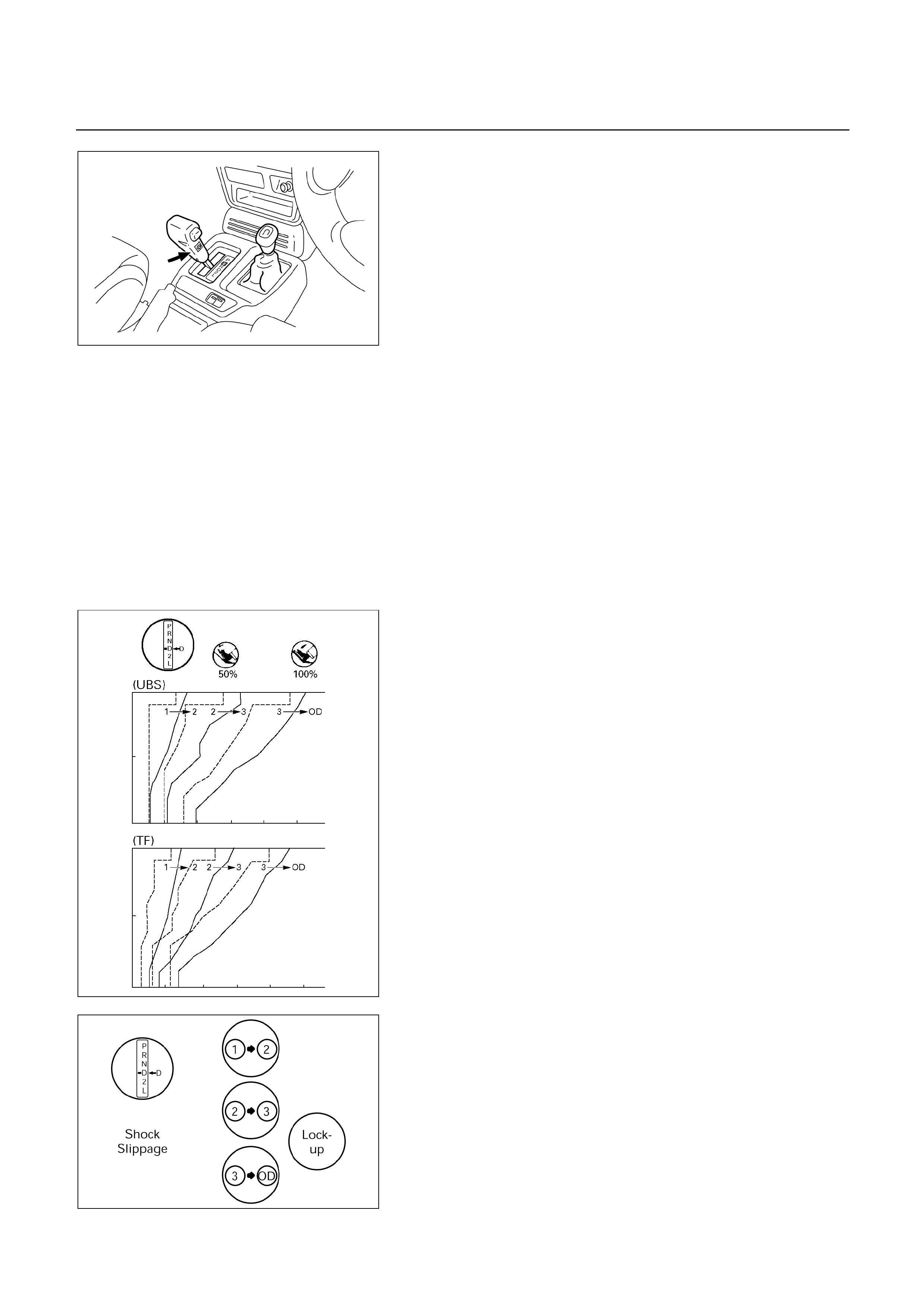
255RT004
F07R200015
F07RY00006
ROAD TEST
NOTE:
Perform the test at normal operation fluid temperature
(50 – 80ººººC or 122 – 176ººººF).
“D” RANGE TEST IN “NORMAL”, AND “POWER”
PATTERN RANGES
Shift into the “D” range and hold the accelerator pedal
constant at the 50% and 100% throttle valve opening
positions.
Push in one of the pattern selector buttons and check the
following:
1. 1-2, 2-3, 3-OD and lock-up, up-shifts should take place,
and shift points should conform to those shown in the
automatic shift diagram.
NOTE:
Drive the vehicle on level ground.
EVALUATION
(1) If there is no 12 up-shift:
Solenoid S2 is stuck
1-2 shift valve is stuck
(2) If there is no 23 up-shift:
Solenoid S1 is stuck
2-3 shift valve is stuck
(3) If there is no 3OD up-shift (throttle valve opening
1/2):
Solenoid S2 is stuck
3-OD shift valve is stuck
(4) If the shift point is defective:
Refer to “TROUBLESHOOTING CHART” in this
section.
(5) If the lock-up is defective:
Refer to “TROUBLESHOOTING CHART” in this
section.
2. In the same manner, check the shock and slip at the 1
2, 2 3 and 3 OD up-shifts.
EVALUATION
If the shock is excessive:
Refer to “TROUBLESHOOTING CHART” in this
section.
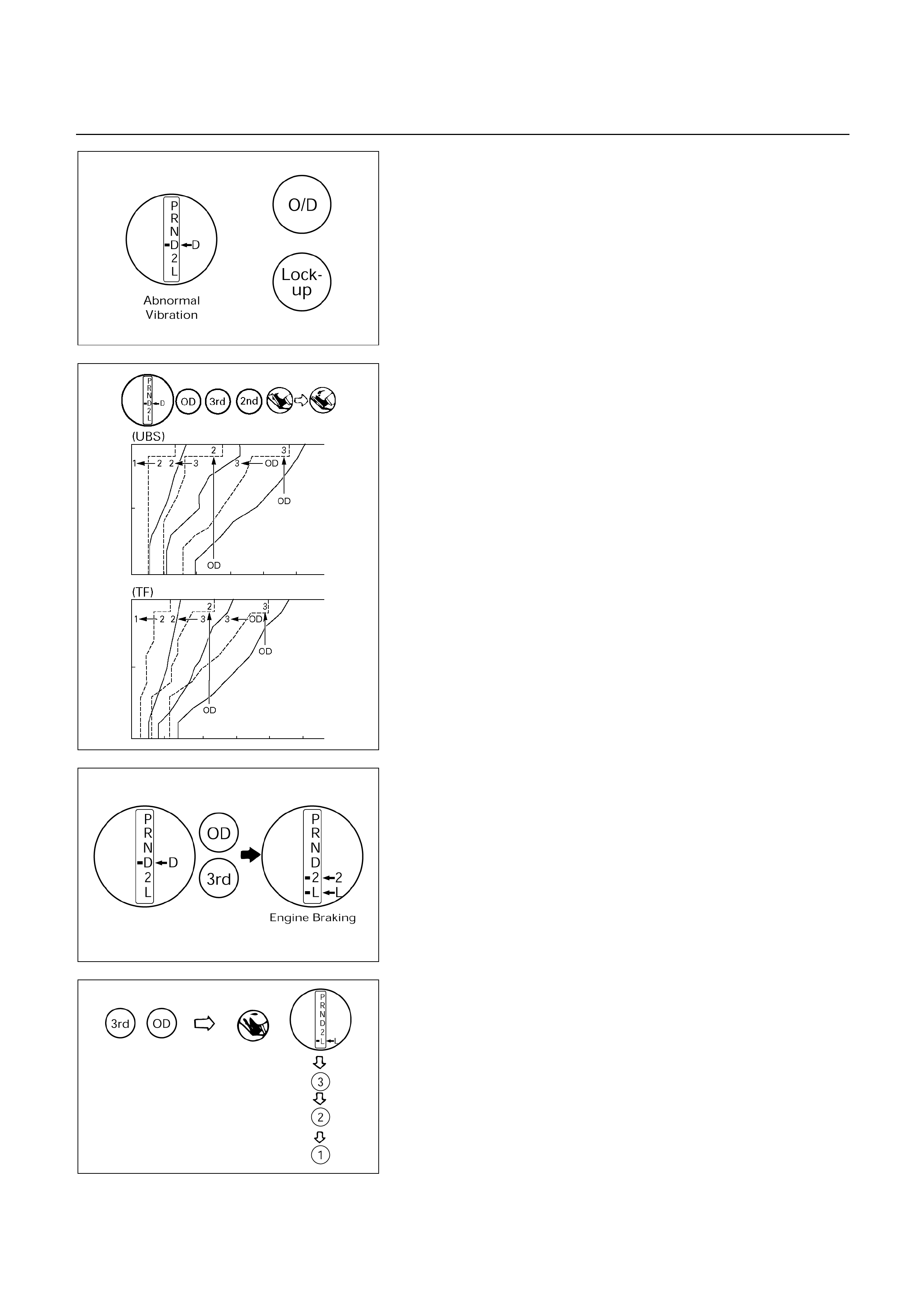
F07RY00007
3. Run at “D” range lock-up or OD gear and check fo
r
abnormal noise and vibration.
NOTE:
The check for the cause of abnormal noise and
vibration must be made with extreme care as it could
also be due to loss of balance in the propeller shaft,
differential, the torque converter, etc. or insufficient
bending, rigidity, etc. in the power train.
F07R200016
4. While running in “D” range, 2nd, 3rd gears and OD,
check to see that the possible kick-down vehicle speed
limits for 2 1, 3 1, 3 2, OD 3 and OD 2 kick-
downs conform to those indicated on the automatic shift
diagram.
5. Check for abnormal shock and slip at kick-down.
6. While running in “D” range, OD gear or “lock-up”, shift
to “2” and “L” ranges and check the engine braking
effect at each of these ranges.
7. Also check to see that downshift is made from 3 2 o
r
from OD to 3 and then to 2 immediately and that 2 1
downshift point is within the limits shown in the diagram
when tested by releasing the accelerator pedal and
shifting into position of “L” while driving in the third gea
r
or in overdrive.
F07RY00009
EVALUATION
(1) If there is no engine braking effect in the “2” range:
Second coast (No.1) brake is defective.
(2) If there is no engine braking effect in the “L” range:
First and reverse (No.3) brake is defective.
F07RY00010
(3) Also check to see that downshift is made from 3 2 o
r
from OD to 3 and then to 2 immediately and that 2 1
downshift point is within the limits shown in the
diagram when tested by releasing the accelerato
r
pedal and shifting into “L” position while driving in the
third gear or in overdrive.
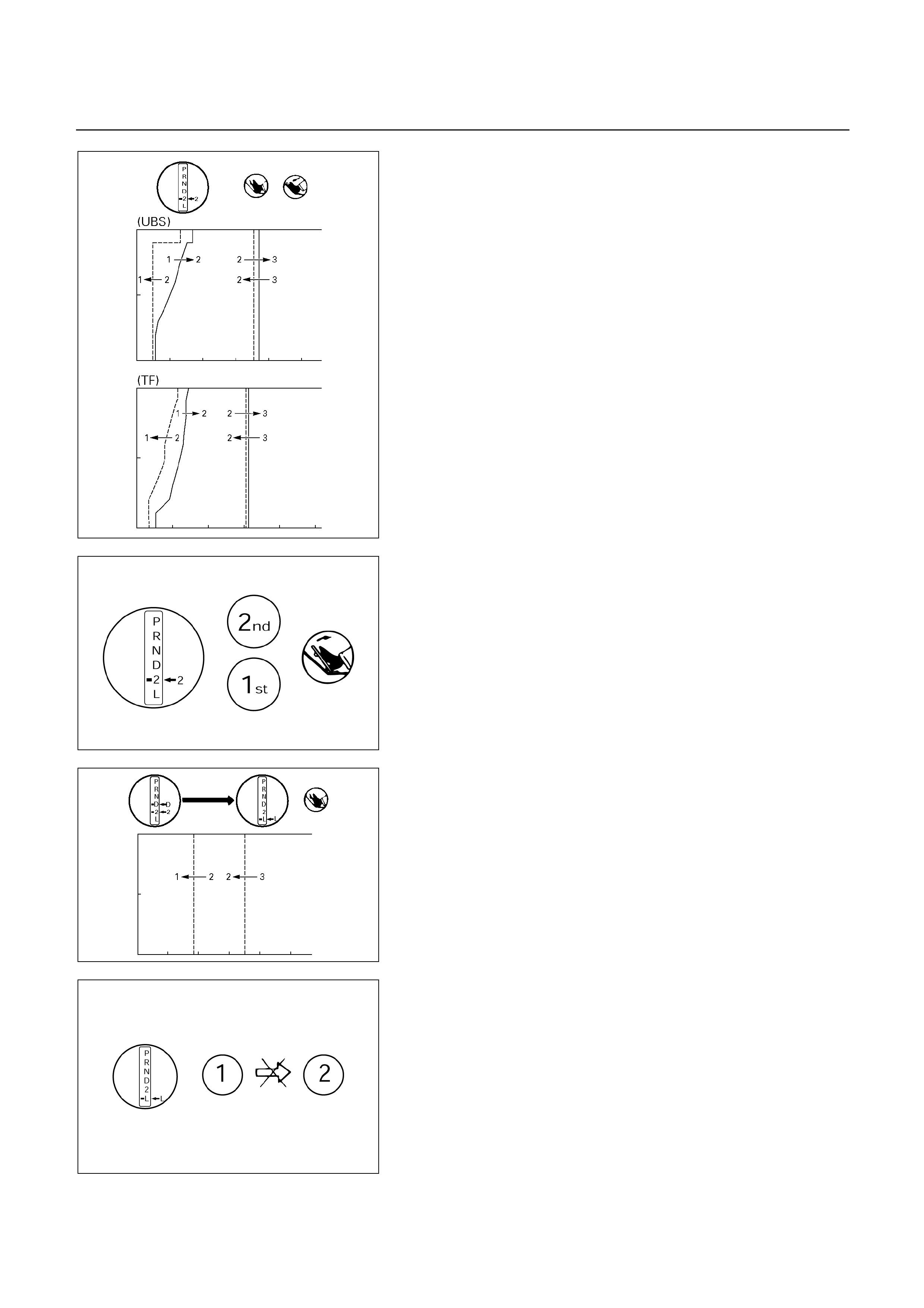
F07R200017
F07RY00012
“2” RANGE TEST
Shift into “2” range and, while driving with the accelerato
r
pedal held constantly at the specified point (throttle valve
opening 50% and 100%), push in one of the pattern
selectors (only for 4 4) and check on the following points.
1. At each of the above throttle openings, check to see
that the 1 2 up-shift takes place and that the shift
points conform to those shown on the automatic shift
diagram.
NOTE:
There is no OD and no lock-up in the “2” range.
2. While running in the “2” range and 2nd gear, release
the accelerator pedal and check the engine’s braking
effect.
3. Check for 2 1 down-shift and abnormal noise at
acceleration and deceleration, and for shock at upshift
and down-shift.
F07R200018
“L” RANGE TEST
1. While running above 80 km/h (50 mph) in the “D” range,
release your foot from the accelerator pedal and shift
into the “L” range.
Then check to see that the 2 1 down-shift occurs at
the specified point shown on the automatic shift
diagram.
F07RY00014
2. While running in the “L” range, check to see that there
is no up-shift to 2nd gear.
3. While running in the “L” range, release the accelerato
r
pedal and check the engine braking effect.
4. Check for abnormal noise during acceleration and
deceleration.

F07RY00015
“R” RANGE TEST
Shift into the “R” range and, while starting at full throttle,
check for slipping.
“P” RANGE TEST
Stop the vehicle on a grade (more than 9%) and afte
r
shifting into the “P” range, release the parking brake.
Then check to see that the parking lock pawl holds the
vehicle in place.

SHIFT POINT CHART AND LOCK-UP POINT CHART
SHIFT POINT CHART (UBS)
(H2, H4)
(REAR AXLE RATIO: 4.300)
(RADIUS OF TIRE: 0.363m)
“NORMAL” mode
Up shift km/h
Range Throttle Opening 12 2 3 3 4
Fully opened 39 – 45 78 – 84 128 – 134
D Half throttle 22 – 28 48 – 54 89 – 95
Fully opened 39 – 45 89 – 95
2 Half throttle 22 – 28 89 – 95
Down shift km/h
Range Throttle Opening 12 2 3 3 4
Fully opened 30 – 36 65 – 71 115 – 121
Half throttle 9 – 15 27 – 33 64 – 70
D
Fully closed 9 – 15 22 – 28 37 – 43
Fully opened 30 – 36 85 – 91
Half throttle 9 – 15 85 – 91
2
Fully closed 9 – 15 85 – 91
Fully opened 43 – 49 85 – 91
Half throttle 43 – 49 85 – 91
L
Fully closed 43 – 49 85 – 91
“POWER” mode
Up shift km/h
Range Throttle Opening 12 2 3 3 4
Fully opened 39 – 45 78 – 84 128 – 134
D Half throttle 29 – 35 58 – 64 89 – 95
Fully opened 39 – 45 89 – 95
2 Half throttle 22 – 28 89 – 95
Down shift km/h
Range Throttle Opening 12 2 3 3 4
Fully opened 30 – 36 65 – 71 115 – 121
Half throttle 11 – 17 45 – 51 74 – 80
D
Fully closed 9 – 15 22 – 28 37 – 43
Fully opened 30 – 36 85 – 91
Half throttle 9 – 15 85 – 91
2
Fully closed 9 – 15 85 – 91
Fully opened 43 – 49 85 – 91
Half throttle 43 – 49 85 – 91
L
Fully closed 43 – 49 85 – 91

LOCK-UP POINT CHART (UBS)
(H2, H4)
(REAR AXLE RATIO: 4.300)
(RADIUS OF TIRE: 0.363m)
km/h
Throttle Opening: 20 %
Lock-up ON Lock-up OFF
Range A/T Mode
3rd 4th 3rd 4th
NORMAL 47 – 53 62 – 68 45 – 51 55 – 61
D POWER 47 – 53 66 – 72 45 – 51 62 – 68
SHIFT POINT CHART (TFR/S)
(H2, H4)
(REAR AXLE RATIO: 4.555)
(RADIUS OF TIRE: 0.348m)
“NORMAL” mode
Up shift km/h
Range Throttle Opening 12 2 3 3 4
Fully opened 34 – 40 71 – 77 112 – 118
D Half throttle 24 – 30 44 – 50 75 – 81
Fully opened 34 – 40 76 – 82
2 Half throttle 28 – 34 76 – 82
Down shift km/h
Range Throttle Opening 12 2 3 3 4
Fully opened 26 – 32 57 – 63 97 – 103
Half throttle 9 – 15 27 – 33 49 – 55
D
Fully closed 5 – 11 13 – 19 26 – 32
Fully opened 26 – 32 74 – 80
Half throttle 17 – 23 74 – 80
2
Fully closed 5 – 11 74 – 80
Fully opened 38 – 44 74 – 80
Half throttle 38 – 44 74 – 80
L
Fully closed 38 – 44 74 – 80
“POWER” mode
Up shift km/h
Range Throttle Opening 12 2 3 3 4
Fully opened 34 – 40 71 – 77 112 – 118
D Half throttle 28 – 34 52 – 58 79 – 85
Fully opened 34 – 40 76 – 82
2 Half throttle 28 – 34 76 – 82
Down shift km/h
Range Throttle Opening 12 2 3 3 4
Fully opened 26 – 32 57 – 63 97 – 103
Half throttle 17 – 23 42 – 48 66 – 72
D
Fully closed 5 – 11 13 – 19 26 – 32
Fully opened 26 – 32 74 – 80
Half throttle 17 – 23 74 – 80
2
Fully closed 5 – 11 74 – 80
Fully opened 38 – 44 74 – 80
Half throttle 38 – 44 74 – 80
L
Fully closed 38 – 44 74 – 80

LOCK-UP POINT CHART (TFR/S)
(H2, H4)
(REAR AXLE RATIO: 4.555)
(RADIUS OF TIRE: 0.348m)
km/h
Throttle Opening: 20 %
Lock-up ON Lock-up OFF
Range A/T Mode
2nd 3rd 4th 2nd 3rd 4th
NORMAL 32 – 38 46 – 52 56 – 62 26 – 32 42 – 48 54 – 60
D POWER 32 – 38 46 – 52 56 – 62 26 – 32 42 – 48 54 – 60
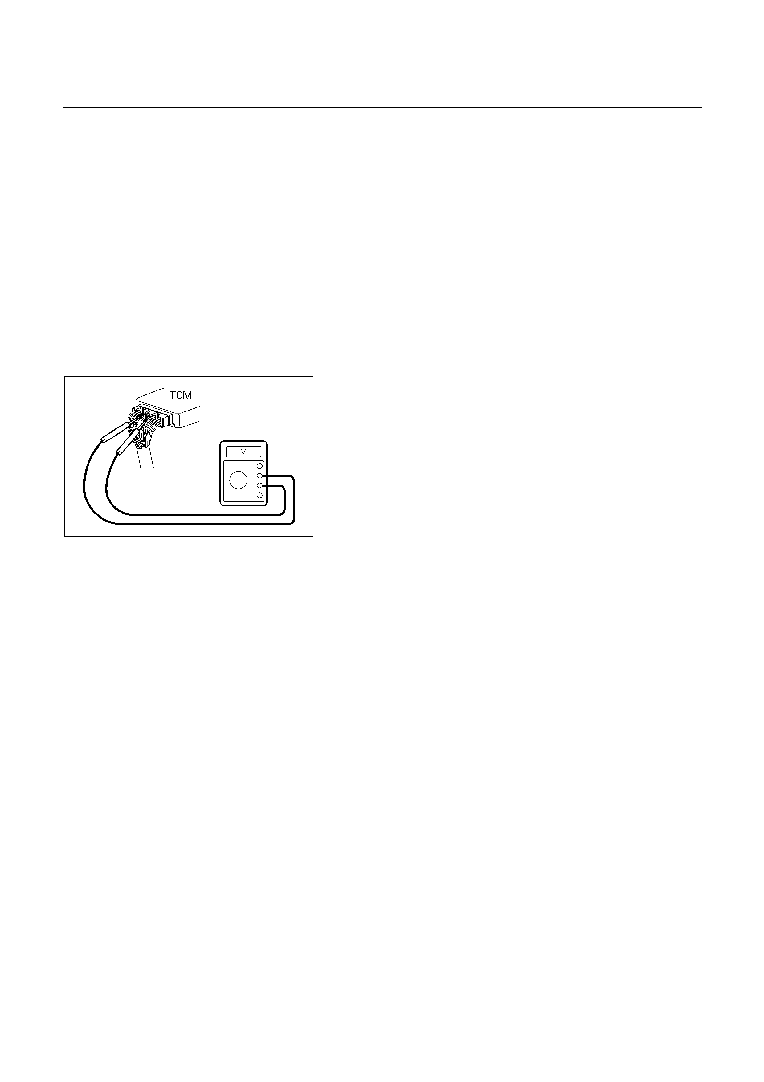
TCM VOLTAGE CHECK
TCM voltage check is done to check for transmission and
transmission control module (TCM) problems which cannot
be detected by self-diagnosis.
Additionally, it serves as a back-up check for self-
diagnosis.
Measure the voltage drop and make a continuity test fo
r
each of the sensors, solenoids, and switches.
If the voltage is within the specified range and continuit
y
exists, that particular area of the TCM and automatic
transmission assembly is normal.
If voltage deviation or lack of continuity is discovered,
disconnect the applicable parts and check each of them
individually.
This will allow you to determine the trouble location (TCM,
automatic transmission unit, or another area of the
vehicle).
826RY00017
Inspection Tool
Use a circuit tester to measure voltage and circuit
continuity.
Insert the test probes from the connector wiring side. TCM
terminals are extremely small.
Wrap a piece of thin wire around the probe of tester.
This will make measurement easier.
NOTE:
TCM is located in the behind instrument panel of the
driver’s compartment.
TCM Voltage Check Procedure
1. Remove the TCM.
2. Turn the ignition switch on. Do not start the engine.
3. Measure the voltage at the terminal.
Refer the following table for the specified voltage
ranges.
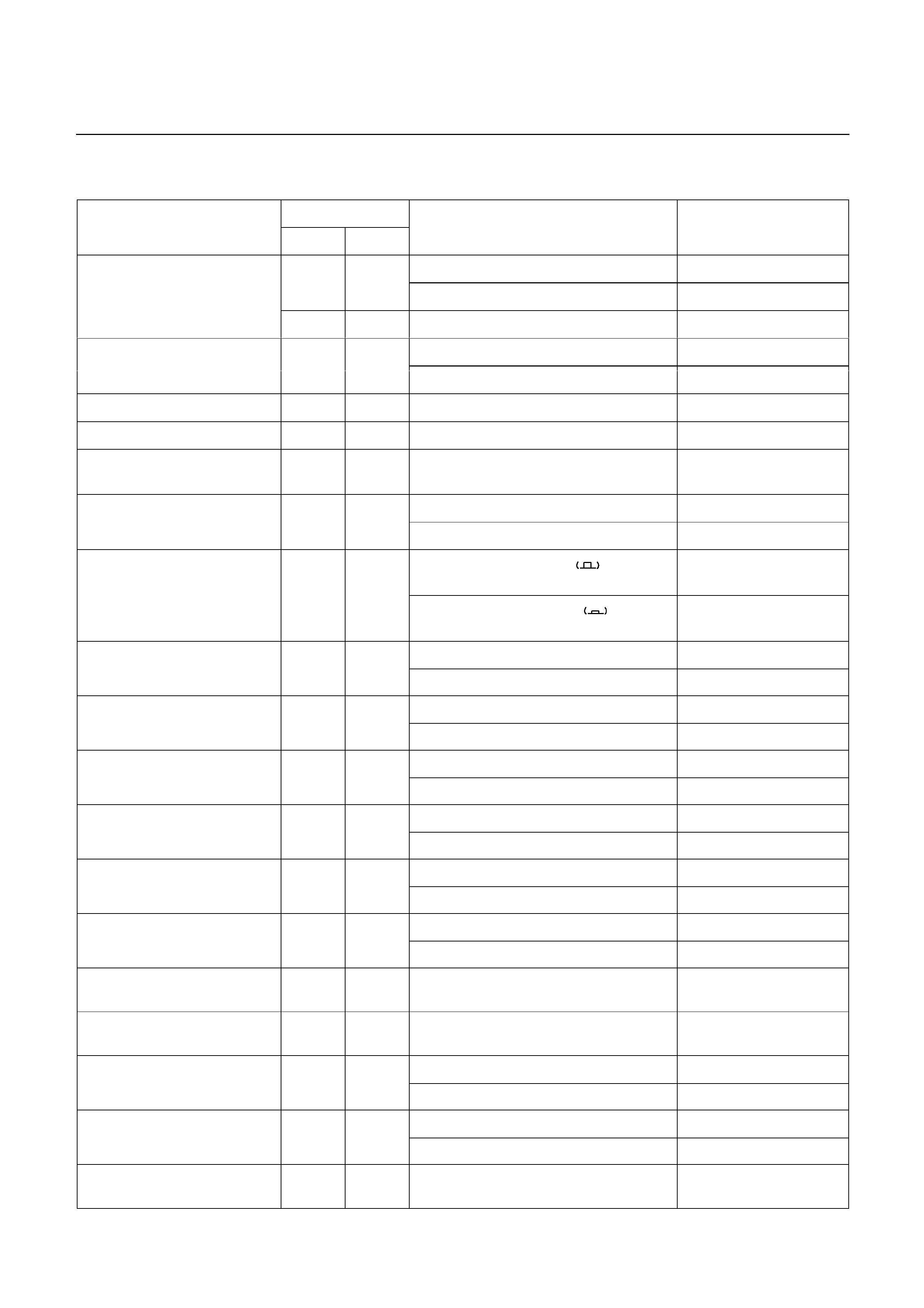
TCM STANDARD VOLTAGE
Terminal
Check circuit
+ –
Measuring condition Voltage (V)
Throttle fully closed (Idling) 0.25 ∼ 0.45
C79-6 C79-28
Throttle fully opened (WOT) 3.47 ∼ 4.56
Throttle position sensor
(UBS)
C79-19 C79-28 Key switch ON 4.75 ∼ 5.25
Throttle fully closed (Idling) (*1) 4.4 ∼ 4.6
Throttle position sensor
(TFR/S) C79-6 C78-15
or –19 Throttle fully opened (WOT) (*1) 0.4 ∼ 0.6
Output revolution sensor C79-4 C79-16 Engine idling in gear 0 ∼ 3
Input revolution sensor C79-5 C79-17 Engine idling 0 ∼ 3
Speed meter sensor C79-7 C78-15
or –19
Vehicle speed 10 ∼ 20 km/h Less than 1.4
⇔ about 5
Depress brake 7 ∼ 16
Brake switch C78-18 C78-15
or –19 Release brake Less than 1
O/D switch position ON
(O/D OFF lamp OFF) Less than 1
O/D switch C79-3 C78-15
or –19 O/D switch position OFF
(O/D OFF lamp ON) 7 ∼ 16
Selector “P” range 7 ∼ 16
Neutral start switch
(P) C79-2 C78-15
or –19 Selector all ranges except “P” Less than 1
Selector “R” range 7 ∼ 16
Neutral start switch
® C79-1 C78-15
or –19 Selector all ranges except “R” Less than 1
Selector “N” range 7 ∼ 16
Neutral start switch
(N) C79-9 C78-15
or –19 Selector all ranges except “N” Less than 1
Selector “D” range 7 ∼ 16
Neutral start switch
(D) C79-8 C78-15
or –19 Selector all ranges except “D” Less than 1
Selector “2” range 7 ∼ 16
Neutral start switch
(2) C79-21 C78-15
or –19 Selector all ranges except “2” Less than 1
Selector “L” range 7 ∼ 16
Neutral start switch
(L) C79-20 C78-15
or -19 Selector all ranges except “L” Less than 1
Engine revolution signal C79-15 C78-15
or -19
Engine idling Less than 1.4 ⇔ 9 ∼ 16
Diagnosis terminal C79-24 C78-15
or -19
Self-diagnosis ON 0 ∼ 1.5
Power pattern switch OFF (NORMAL) 8 ∼ 16
Power pattern switch C79-23 C78-15
or -19 Power pattern switch ON (POWER) Less than 1.4
Switch OFF 8 ∼ 16
Winter select switch C79-13 C78-15
or -19 Switch ON Less than 1.4
Electrical source (Battery) C78-13 C78-15
or -19
9 ∼ 16
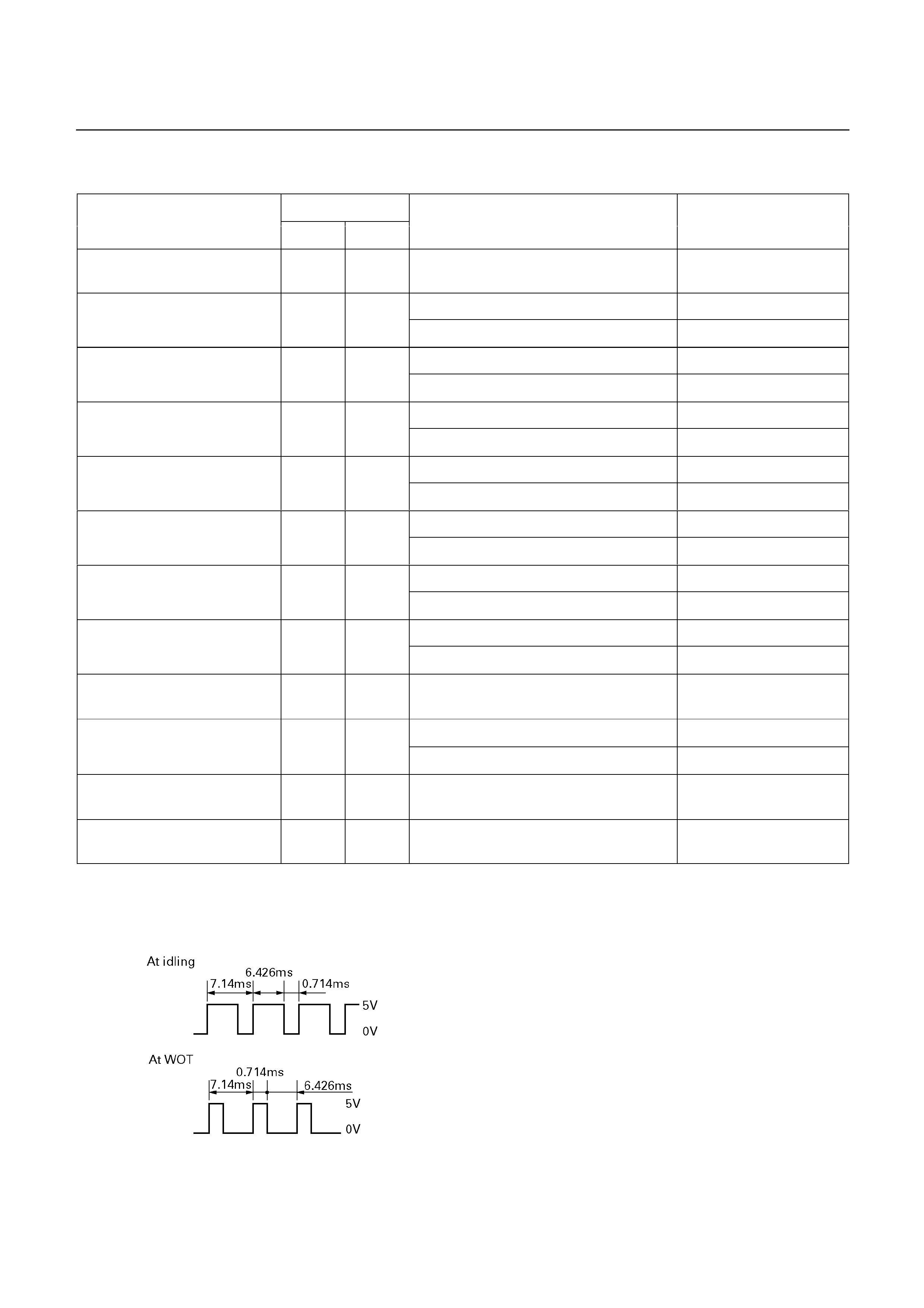
Terminal
Check circuit
+ –
Measuring condition Voltage (V)
Electrical source (Ignition) C78-20 C78-15
or -19
Key switch ON 9 ∼ 16
Oil temperature warning lamp ON Less than 1
Oil temperature warning
lamp C79-11 C78-15
or -19 Oil temperature warning lamp OFF 8 ∼ 16
“CHECK TRANS” lamp ON Less than 1
“CHECK TRANS lamp” C79-10 C78-15
or -19 “CHECK TRANS” lamp OFF 8 ∼ 16
Power lamp ON Less than 1
Power lamp (UBS) C79-22 C78-15
or -19 Power lamp OFF 8 ∼ 16
Winter lamp ON Less than 1
Winter lamp (UBS) C79-12 C78-15
or -19 Winter lamp OFF 8 ∼ 16
OFF (3rd or O/D) Less than 1
Solenoid S1 C78-4 C78-15
or -19 ON (1st or 2nd) 8 ∼ 16
OFF (1st or O/D) Less than 1
Solenoid S2 C78-3 C78-15
or -19 ON (2nd or 3rd) 8 ∼ 16
OFF (Lock up OFF) Less than 1
Lock up solenoid SL C78-12 C78-15
or -19 ON (Lock up ON) 8 ∼ 16
Pressure control solenoid C78-11 C78-8 At throttle pressure changing Less than
1 ⇔ 8-16
ATF temperature 20° 4.70
Oil temperature sensor C79-18 C79-27
ATF temperature 80°C 3.65
Tech 2 diagnosis terminal
(J1850) C78-6 C78-15
or -19
On diagnosis communication 0-1.5 ⇔
6.25-8.0
Throttle position sensor
(ground) (UBS) C79-19 C78-15
or -19
Key switch ON -0.1 ∼ 0.1
*1: Reference (Oscilloscope waveform)
(TFR/S)
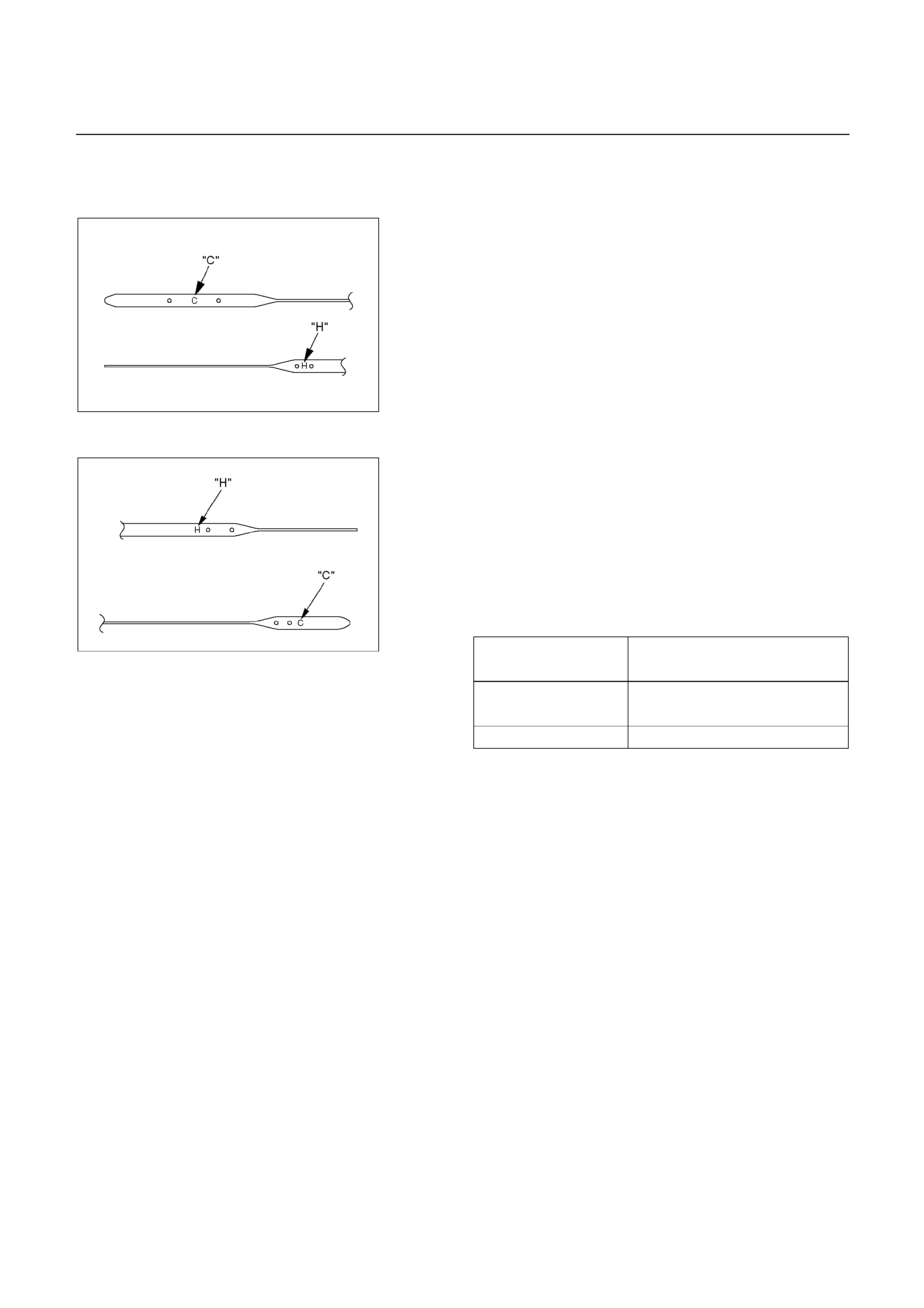
ON-VEHICLE SERVICE
UBS
242R200004
TRANSIMISSION FLUID LEVEL AND
CONDITION
Park vehicle on level ground and set parking brake.
With the engine idling, move the shift lever through all
positions from "P" to "L", then return to position "P".
Check to see If the level of fluid comes to "HOT" range o
f
about 80°C (176°F) on the dipstick gauge.
If the level of fluid is too low, replenish to bring it to
maximum level in "HOT" range.
Inspection of fluid condition
If the ATF is black or smells burnt, replace it.
ATF REPLACEMENT
NOTE:
Do not overfill.
1. Remove the drain plug from oil pan and drain the fluid.
2. Reinstall the drain plug securely.
Torque: 19 N m (1.9 kg m/14 Ib ft)
3. With the engine OFF, add new fluid through the fille
r
tube.
5.2 litres
Drain and refill
8.7 litres
Dry fill
Fluid DEXRON ATF
TF
242R200005
4. Start the engine and shift the selector into all position
from "P" through "L", and then shift into "P".
5. With the engine idling, check the fluid level. Add fluid up
to the "COLD" level on the dipstick.
6. The ATF level must be checked again for correct level
with the "HOT" level.
NOTE:
To prevent fluid leaks, the drain plug gasket must be
replaced each time this plug is removed.
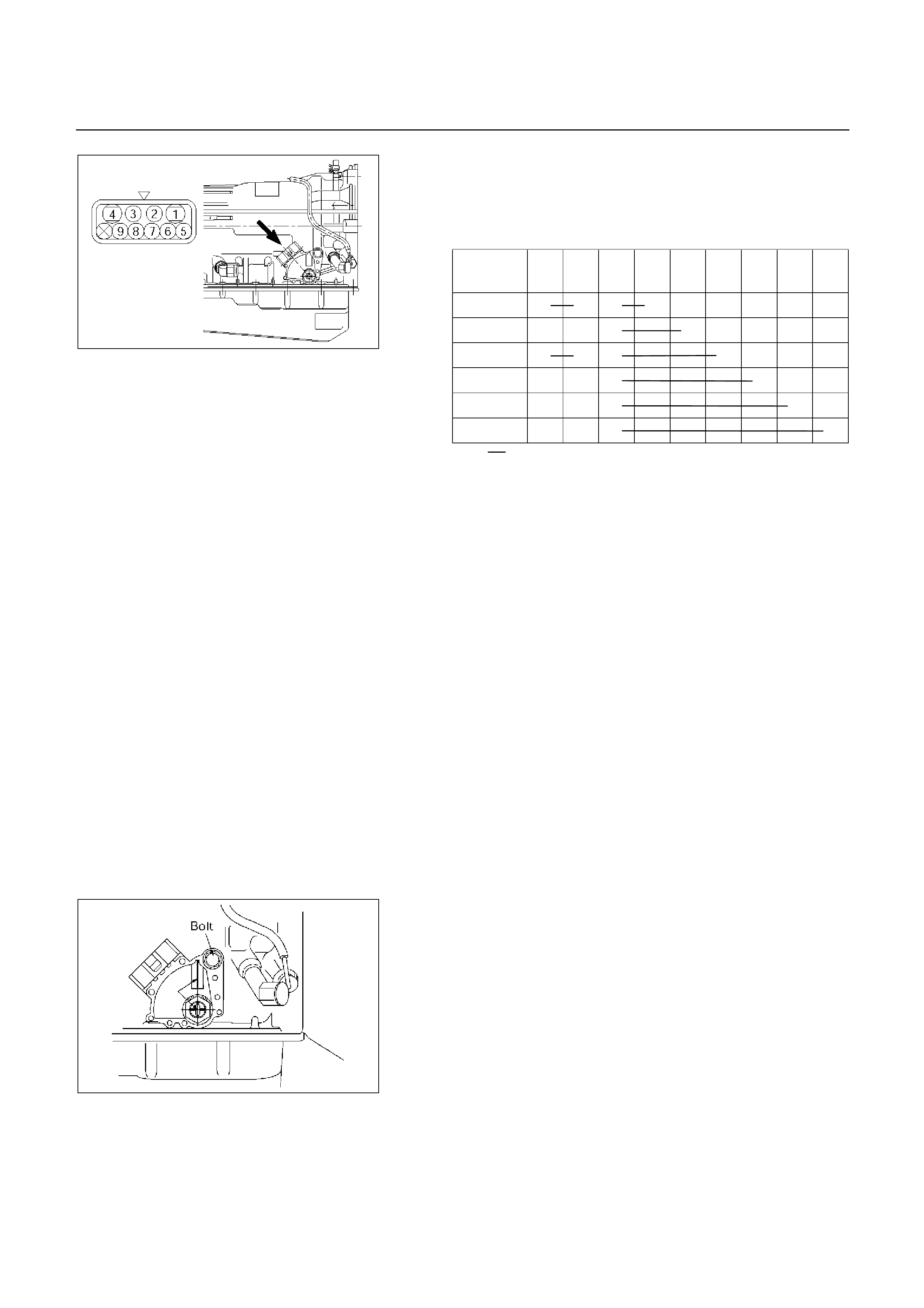
NEUTRAL START SWITCH INSPECTION
Inspection
With a circuit tester, make a continuity test on the neutral
start switch with the moving piece set in each position.
Terminal
Position 1 4 3 5 2 6 8 7 9
P
R
N
D
2
L
249RY00010
Continuity
Removal
Preparation:
Disconnect negative (-) battery cable.
1. Remove rear sound cover (UBS).
2. Remove the rear side ATF cooler pipe from the
transmission elbow.
3. Disconnect neutral start switch connector.
4. Unstake the lock washer, and then remove the shaft
nut.
5. Remove the neutral start switch.
Installation
To install, follow the removal steps in the reverse order,
noting the following points;
Torque:
Nut – 7 N m (0.7 kg m/61 Ib in)
Bolt – 13 N m (1.3 kg m/113 Ib in)
249RY00008
Adjustment
1. Loosen the neutral start switch bolt and set the shift
selector to the “N” range.
2. Align the groove and neutral basic line.
3. Hold in position and tighten the bolt.
Torque: 13 N m (1.3 kg m/113 Ib in)
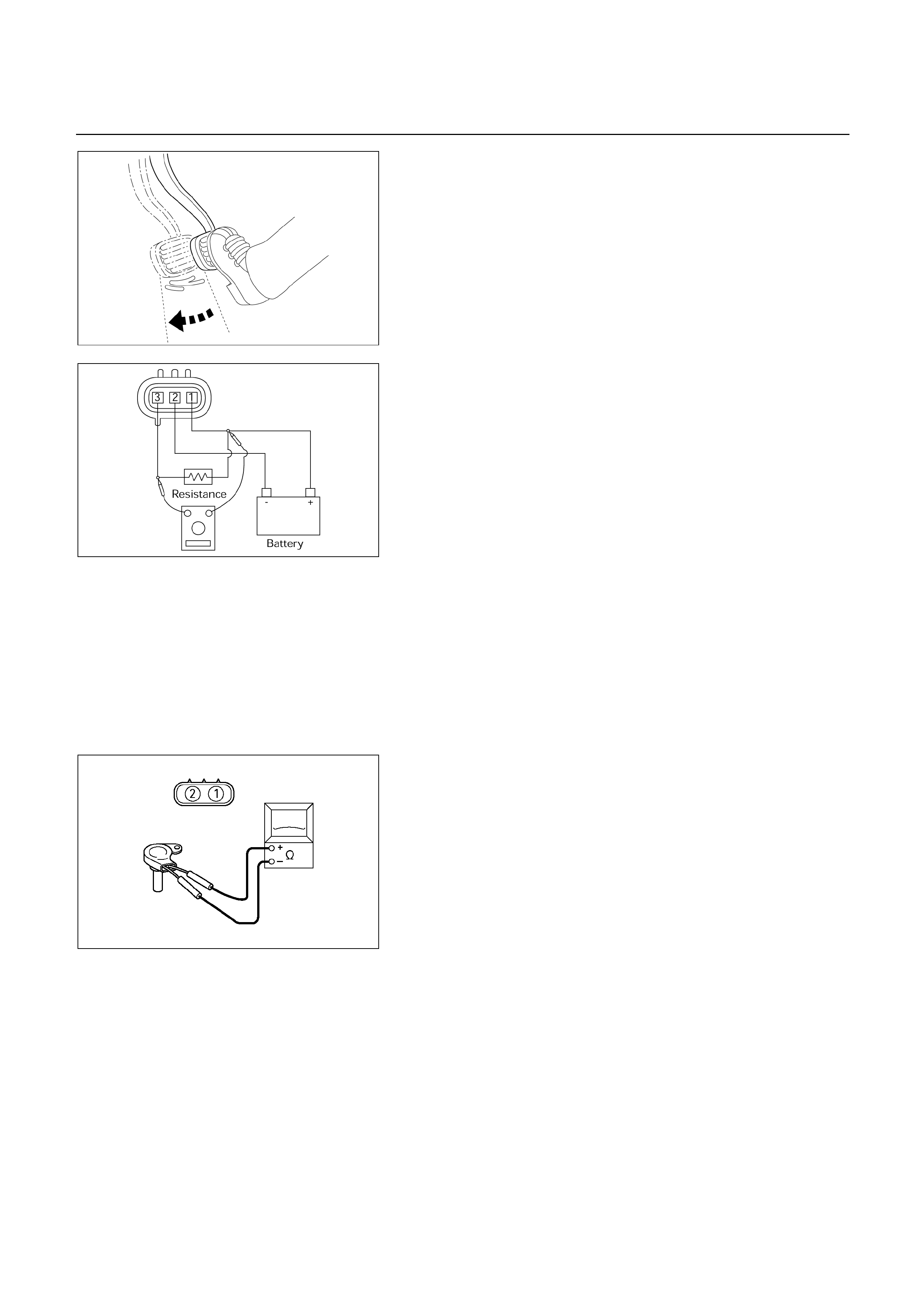
310RW020
BRAKE SIGNAL INSPECTION
Check that the brake light comes on when the brake pedal
is depressed.
F07RY00017
VEHICLE SPEED SENSOR INSPECTION
1. Connect the vehicle speed sensor connector terminal
(1) to the battery ( +) terminal and terminal (2) to the
battery (-) terminal.
2. Connect a resistance of 1.3k ohm to 5k ohm (1.4W o
r
more) between terminals (1) and (3).
NOTE:
Be extremely careful not to connect the battery (+)
terminal to the terminal (3).
This may damage the vehicle speed sensor.
3. Rotate the shaft of the vehicle speed sensor slowly and
measure the voltage at both ends with a digital tester.
The voltage, with one rotation of shaft, fluctuates fou
r
times in the following range: 10 to 14V 2V or less.
Replace the sensor when the result of inspection is
found abnormal.
F07RY00018
INPUT AND OUTPUT REVOLUTION
SENSOR INSPECTION
1. Disconnect the input and output revolution senso
r
connector.
2. Use an ohmmeter to measure the resistance between
terminals 1 and 2.
Standard resistance
Input revolution sensor: 387 – 473 (at 20 , 4 2)
560 – 680 (at 20 , 4 4)
Output revolution sensor: 560 – 680 (at 20 )
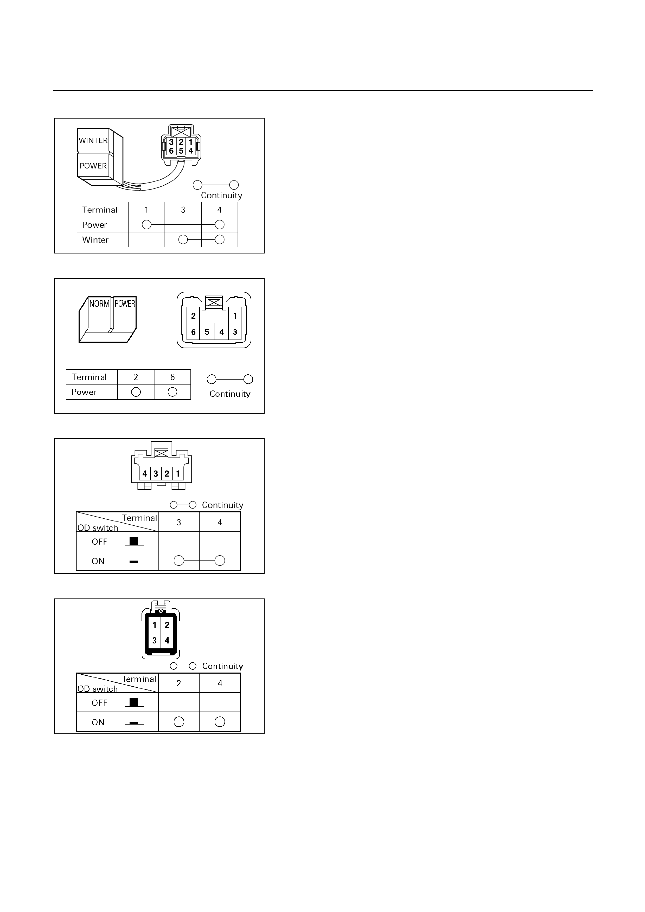
UBS
F07RY00019
TF
F07L100005
PATTERN SELECT SWITCH INSPECTION
Inspect that there is continuity between each terminals.
UBS
225R200003
TF
225L200001
OVERDRIVE SWITCH INSPECTION
Inspect that there is continuity between each terminals.
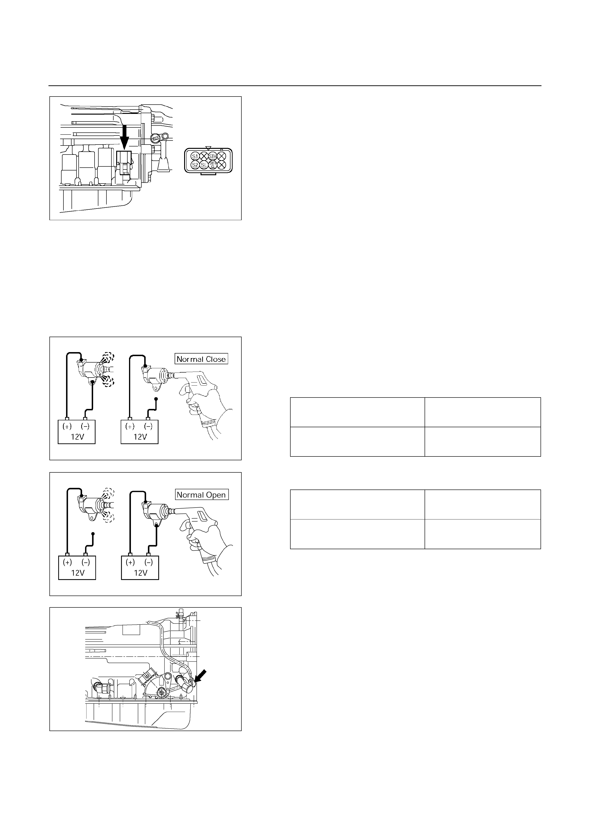
220L100001
SOLENOID INSPECTION
1. Resistance check
Using an ohmmeter, check the resistance between
each terminals (S1/S2/SL) and body.
Solenoid S1, S2 and lock-up solenoid resistance:
11 – 15 (at 20 )
12 – 16 (at 40 )
Using an ohmmeter, check the resistance between
each terminals (STH) and (STHG).
Pressure control solenoid resistance:
5 – 5.6 (at 20 )
5.4 – 6.1 (at 40 )
NOTE:
If the pressure control solenoid resistance is not
within specification, replace the valve body
assembly.
2. Operation check
Check the solenoid operation by blowing into an oil hole
as shown in the figure.
Solenoid S1 and S2 (Normal close type)
When battery terminal is
disconnected No air leaks
When battery terminal is
connected Air passes through
244RX00001
Lock-up solenoid S3 (Normal open type)
When battery terminal is
disconnected Air passes through
When battery terminal is
connected No air leaks
244RY00005
249L100001
ATF TEMPERATURE SENSOR
INSPECTION
1. Disconnect the front side ATF cooler pipe from the
elbow and remove the elbow.
2. Remove the ATF temperature sensor from the
transmission case.
3. Place the ATF temperature sensor in a container o
f
ATF.
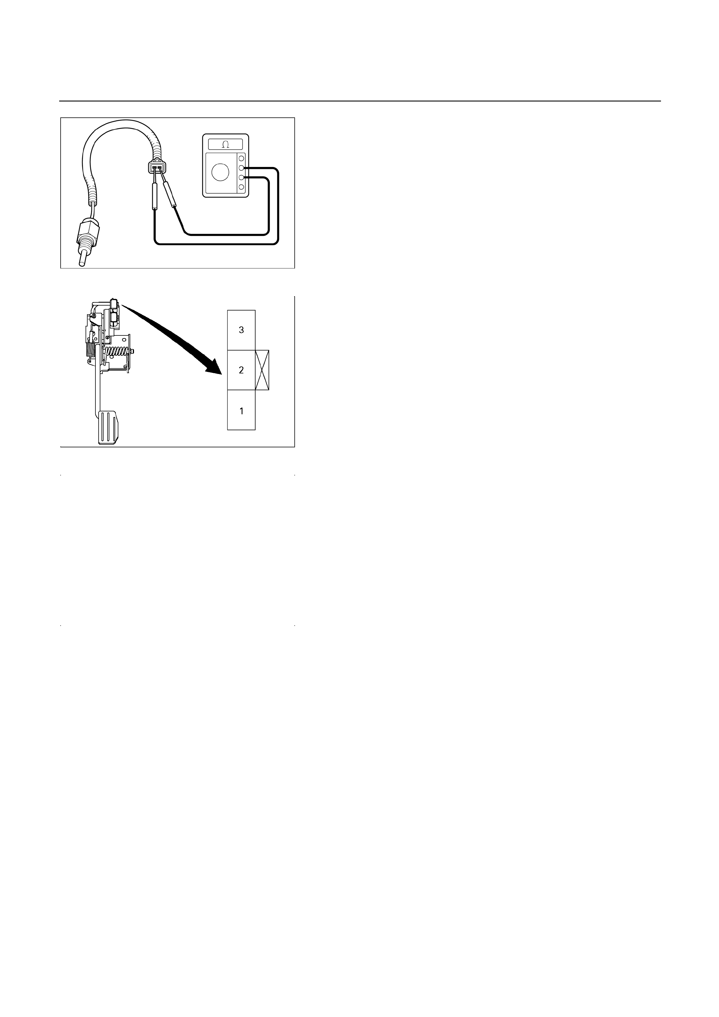
242RW013
4. Measure the resistance between each terminals.
Resistance: 0.5 – 30 k (at 0 - 120)
5. If either of the measured values exceeds the specified,
replace the ATF temperature sensor.
Torque: 15 Nm (1.5 kgm/11 Ibft)
THROTTLE POSITION SENSOR
INSPECTION (UBS and TFR/S)
1. Turn the starter switch to the “ON” position.
2. Measure the voltage between throttle position senso
r
connector terminals 2 (output) and 1 (ground).
NOTE:
Do not remove the sensor connector.
Make sure that power source (4.75 – 5.25V) is
measured between terminals 1 and 3 before
measurement at step 2.
Standard voltage:
Idling 0.25 – 0.45V
WOT 3.74 – 4.56V
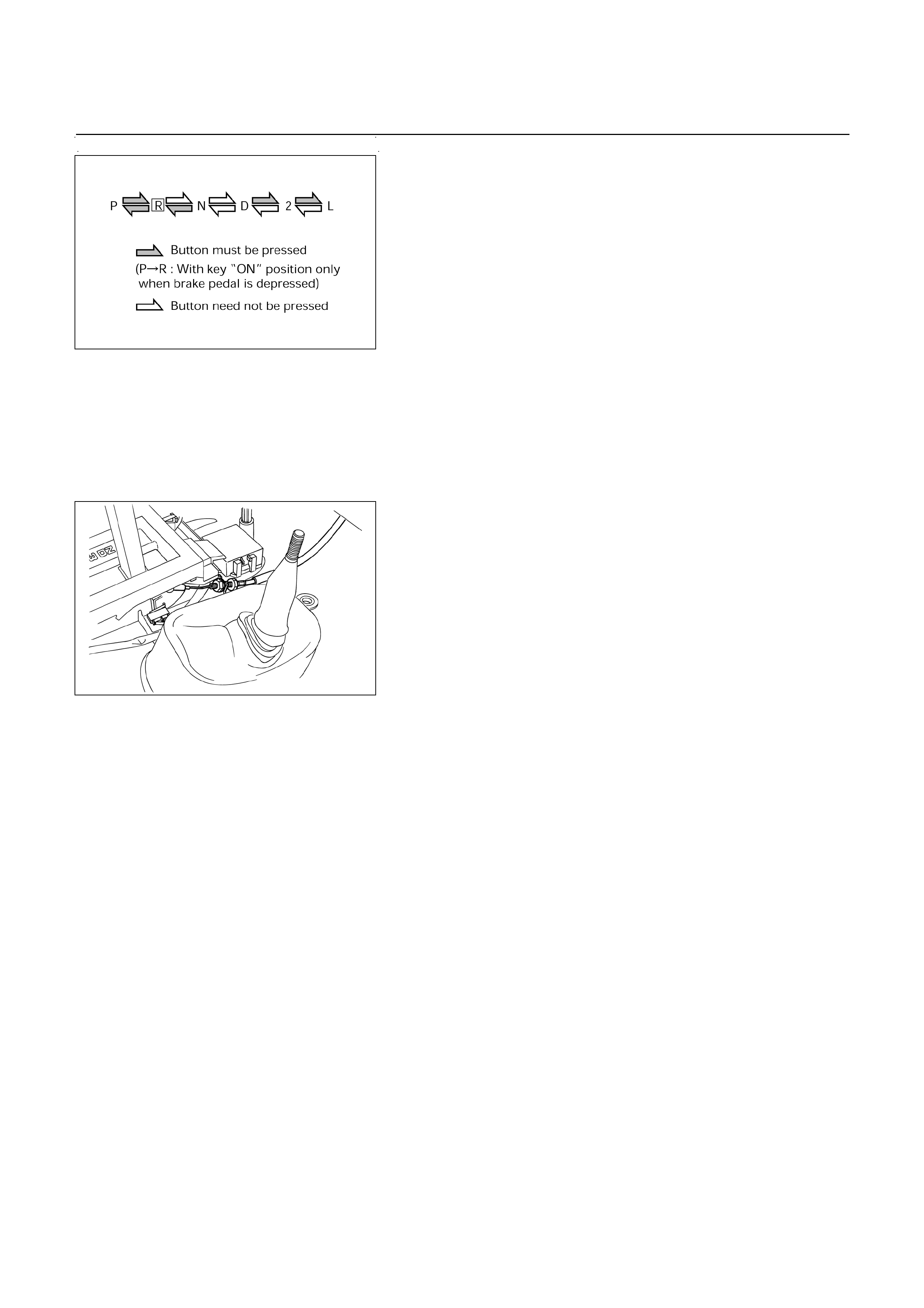
256RY00001
SELECTOR LEVER
Inspection
1. Make sure that when the selector lever is shifted from
"P" to "L", a "clicking" can be felt at each shift position.
Make sure that the gear corresponds to that of the
position plate indicator.
2. Check to see if the selector lever can be shifted as
shown.
REMOVAL
Preparation:
Disconnect negative (-) battery cable.
1. Transfer Control Lever Knob (4 4)
2. Front Console
Disconnect wiring harness connectors.
UBS
256RW012
3. Selector Lever Assembly
1. Disconnect shift lock cable from the selector leve
r
assembly side (UBS).
2. Disconnect wiring harness connectors.
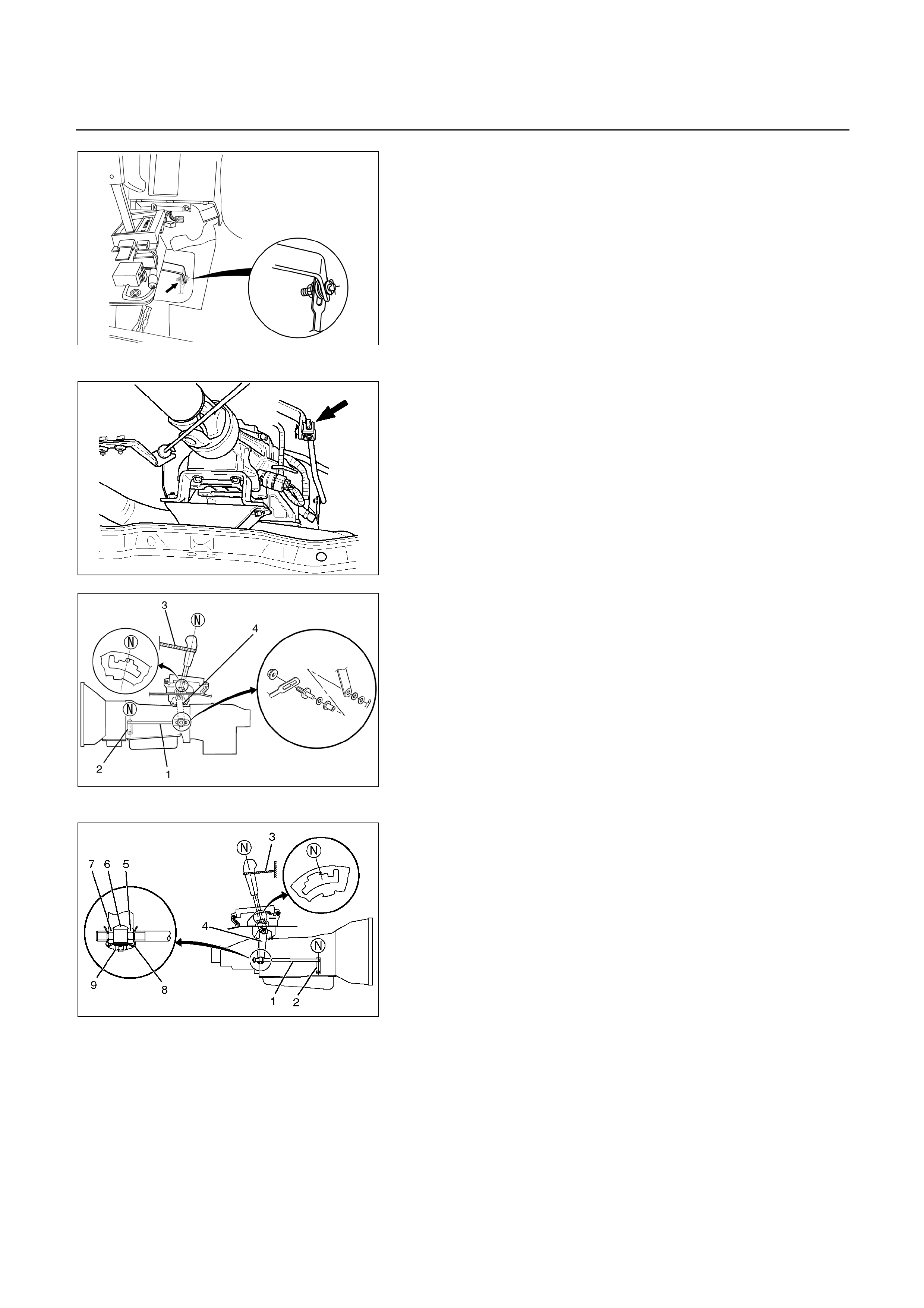
256RW013
3. Disconnect shift control rod from the selector leve
r
assembly side.
’01 TFR
220L200001
256RW014
’01 TFR
256L200001
INSTALLATION
To install, follow the removal steps in the reverse order,
noting the following points;
Adjustment of select lever and control rod
1. Place the vehicle on a level surface.
NOTE:
If the vehicle is not on a level surface, the shift
select cable set position will vary with the
movement of the engine. To prevent possible
misadjustment of the cable, the vehicle must be
placed on a level surface.
2. Install the shift control rod (1) to the transfmission
select lever (2), and then place the lever in the "N"
position.
3. Set select lever in the "N" position.
4. Push selector lever forward and secure it (using a
rubber band (3), etc.) so that pin comes into contact
with the wall of detent plate.
5. Install the shift control rod (1) to the selector lever arm
(4).
Nut torque: 27 N m (2.8 kg m/20 Ib ft)
NOTE:
Do not apply oil to threaded portions.

6. (’01 TFR)
a. Turn nut (5) until it butts against boss (6).
b. Tighten nut (7) to lock boss while keeping nut (5)
stationary with a tool.
Nut torque: 27 N m (2.8 kg m/20 Ib ft)
c. Attach clip (8) and fix it with nut (9).
Nut torque: 7 N m (70 kg cm/61 Ib in)
7. After adjustment, operate select lever on a trial basis to
makes sure of its smooth operation and no abnormal
indication in each position.
256RW015
Adjustment of shift lock cable (UBS)
1. Set ignition key in "LOCK" position and selector lever in
"P" position.
2. Adjust cable screw cap on selector lever side to provide
a gap (slack for cable) of 1-2mm between rod on
steering lock side and stopper
Adjust cap as follows:
a. Pull screw cap (1) in arrow direction to put off slack o
f
inner cable.
b. With cable kept as (a), adjust gap between nut (2)
and bracket to 5mm (0.2in).
c. Lock inner cable by turning nut (3) while holding nut
(2) in place.
Lock nut torque: 3.7 N m (38 kg cm/33 Ib in)
NOTE:
Clean the rod threads and do not apply oil to the
threaded portions.
3. Make sure of proper operation of shift lock through
checks as follows:
a. Selector lever shall not be moved out of "P" position
with ingition key in "Lock" position.
b. Selector lever can be moved out of "P" position with
ignition key in "ON" position only when brake pedal is
depressed.
c. Ignition key can be turned to "LOCK" position onl
y
when selector lever is in "P" position (key can be
pulled out).
If (a) and (c) fail, readjust cable. If (b) fails, readjust
connector wiring and brake pedal switch.
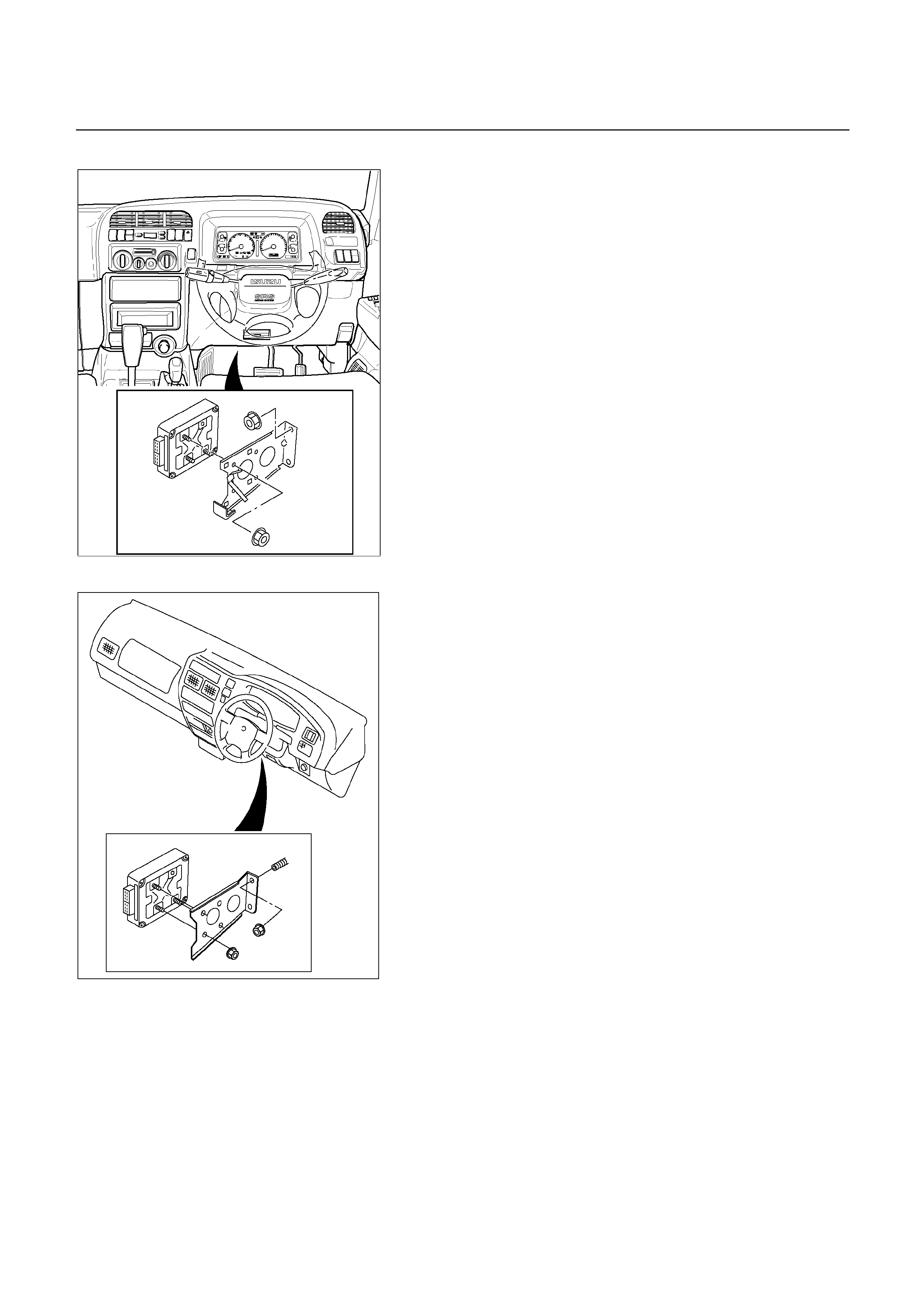
UBS (RHD)
826R200033
TF
826L100002
TRANSMISSION CONTROL MODULE
(TCM)
REMOVAL
Preparation:
Disconnect negative (-) battery cable.
1. Disconnect the TCM harness connectors.
2. Remove fixing nuts (3 pieces) and TCM from the
bracket.
NOTE:
The TCM is fitted under instrument panel of the
driver’s compartment by means of two stud bolts.
INSTALLATION
To install, follow the removal steps in reverse order.

249RY00011
249RY00012
SHIFT SOLENOID AND LOCK-UP
SOLENOID
REMOVAL
Preparation:
Disconnect negative (-) battery cable.
Remove the rear sound cover. (UBS)
Drain the fluid.
Refer to "ATF REPLACEMENT" in this section.
1. Remove the nineteen bolts and oil pan.
2. Remove the oil strainer assembly.
3. Disconnect the solenoid wiring connectors from the
shift solenoid S1(1), S2(2) and lock-up solenoid (3).
4. Remove each retaining bolts and solenoids.
INSTALLATION
To install, follow the removal steps in reverse order noting
the following point;
Torque:
Solenoid S1, S2 bolt 7 N m (0.7 kg m/61 Ib in)
Lock-up solenoid bolt 10 N m (1.0 kg m/87 Ib in)
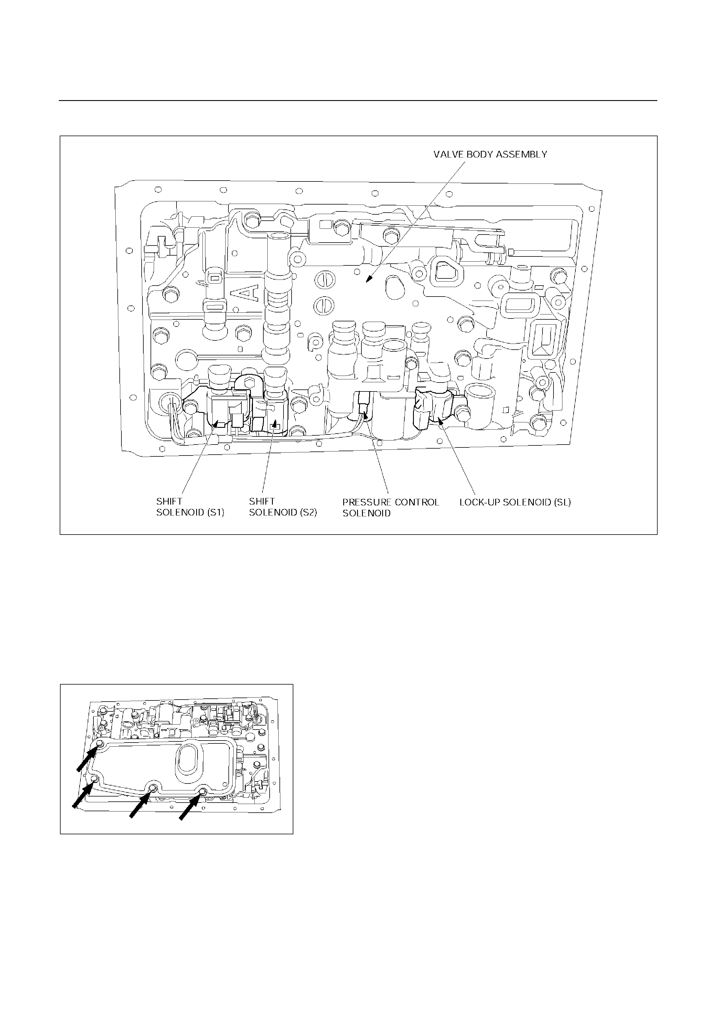
VALVE BODY ASSEMBLY AND PRESSURE CONTROL SOLENOID
244RY00009
REMOVAL
Preparation:
Disconnect negative (-) battery cable.
Remove the rear sound cover. (UBS)
Drain the fluid.
Refer to "ATF REPLACEMENT" in this section.
1. Remove the nineteen bolts and oil pan.
244RY00003
2. Remove the oil strainer assembly.
3. Disconnect the solenoid wiring connectors from the
solenoids.
4. Remove the twenty bolts from the valve body.
5. Remove the valve body assembly and pressure control
solenoid.
When removing valve body assembly from the
transmission case, loosen the solenoid clamp bolt
and remove the pressure control solenoid from the
upper valve body assembly.
Also disconnect the harness connector from the
pressure control solenoid.
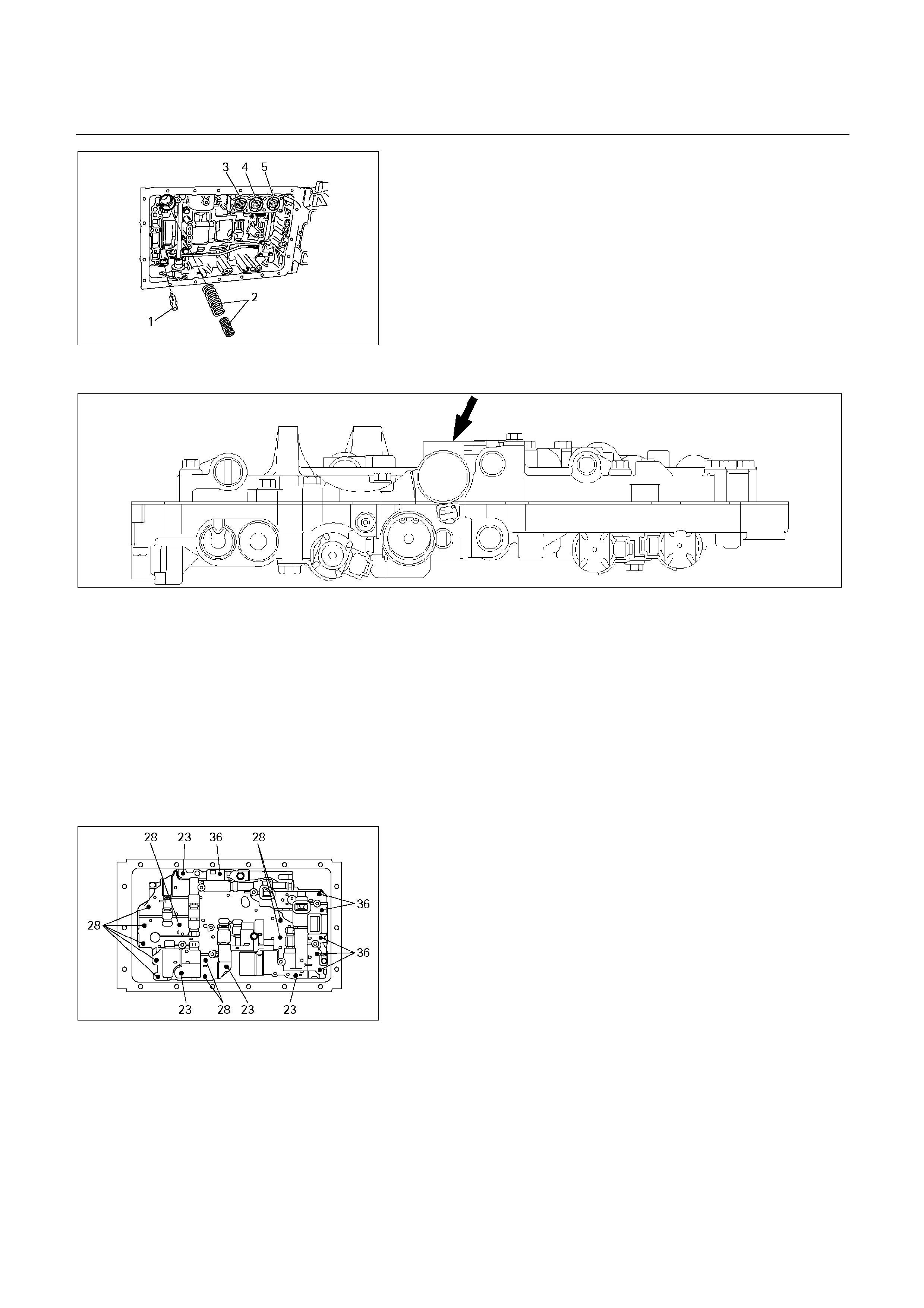
244RY00018
NOTE:
1. Two or more persons are required for removal
and installation of the valve body assembly and
pressure control solenoid.
2. The check valve assembly (1) and the C0
accumulator piston springs (2) will fall from the
transmission case during removal of valve body
assembly.
Protect these parts from damage.
The B0 (3), C2 (4), and B2 (5) accumulator piston
and springs may also fall free and must be
protected.
244RY00006
INSTALLATION
To install, follow the removal steps in reverse order noting
the following point;
1. Reinstall the parts removed with the valve bod
y
assembly to their assigned positions in the
transmission case (check valve assembly, C0
accumulator pistons, etc). Install the valve bod
y
assembly to the transmission case.
Refer to “REASSEMBLY OF MAJOR COMPONENT
S
(2).”
244RY00017
2. Solenoid clamp bolt
Torque : 7 N m (0.7 kg m/61 Ib in)
3. Valve body fixing bolts
Each bolt location and length (mm) is indicated in the
figure.
Torque : 10 N m (1.0 kg m/87 Ib in)
4. Oil strainer fixing bolts
Torque : 10 N m (1.0 kg m/87 Ib in)
5. Oil pan fixing bolts
Torque : 8 N m (0.8 kg m/69 Ib in)
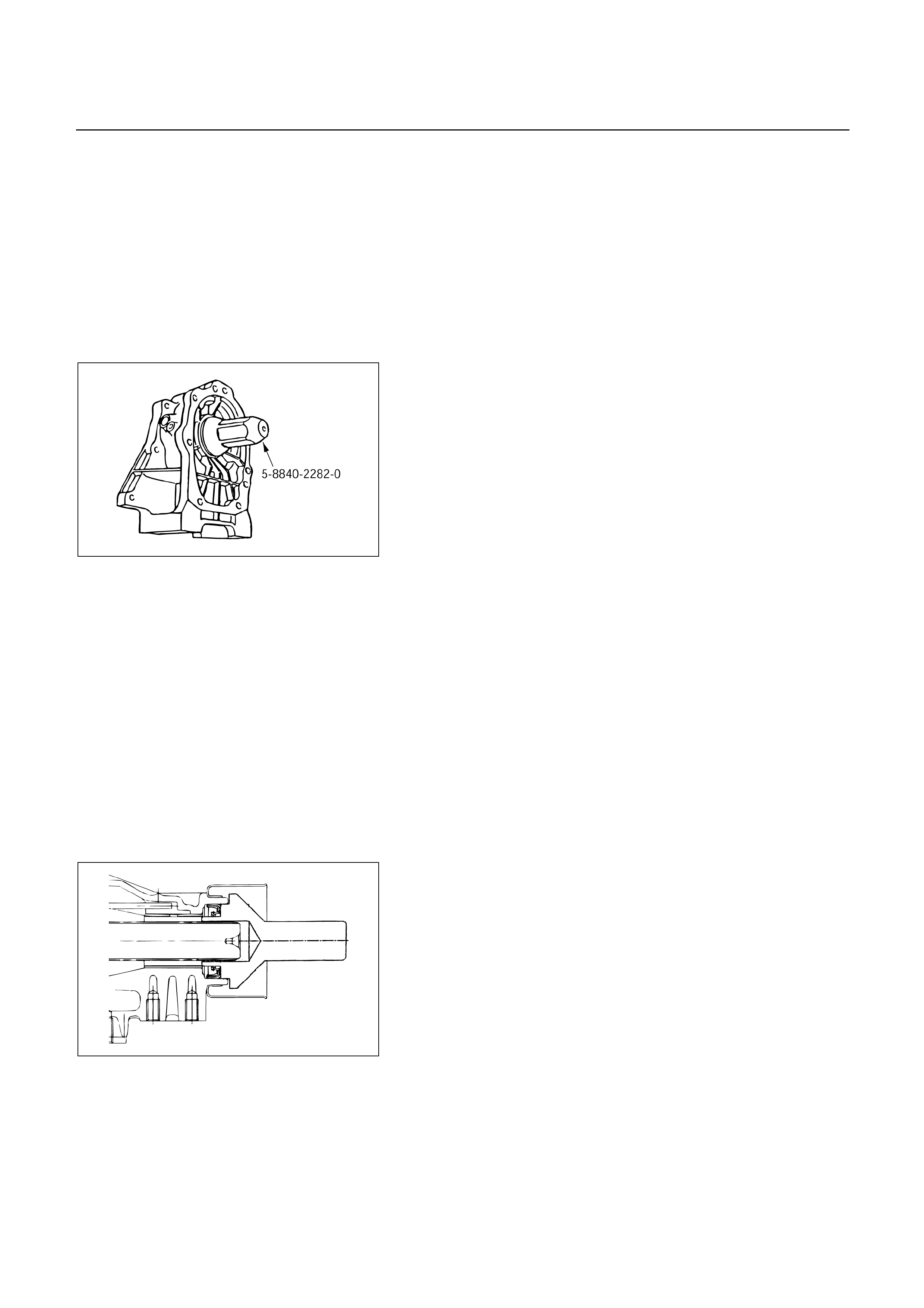
REAR OIL SEAL (ADAPTER HOUSING, 4X4)
REMOVAL
1. Remove the front and rear propeller shaft assembl
y
form the transfer case.
2. Remove the transfer case assembly from the
transmission case.
Refer to Section 4 “DRIVELINE/AXLE”.
3. Using a screwdriver, remove the rear oil seal.
240RY00003
INSTALLATION
1. Apply ATF to a new rear oil seal lip.
2. Using oil seal installer, install the rear oil seal to the
adapter housing.
Oil seal installer : 5-8840-2282-0
3. Install the transfer case assembly.
4. Install the front and rear propeller shaft assembly.
Torque:
Flange bolt : 63 Nm (6.4 kgm/46 Ibft)
Center bearing retainer bolt
: 69 Nm (7.0 kgm/51 Ibft)
REAR OIL SEAL (EXTENSION HOUSING, 4X2)
REMOVAL
1. Remove the rear propeller shaft assembly.
2. Using a screwdriver, remove the rear oil seal.
249L100005
INSTALLATION
1. Apply ATF to a new rear oil seal lip.
2. Using oil seal installer, install the rear oil seal to the
extension housing.
Oil seal installer : 5-8840-2702-0
3. Install the rear propeller shaft.
Torque:
Flange bolt : 63 N m (6.4 kg m/46 Ib in)
Center bearing retainer bolt
: 69 N m (7.0 kg m/51 Ib ft)
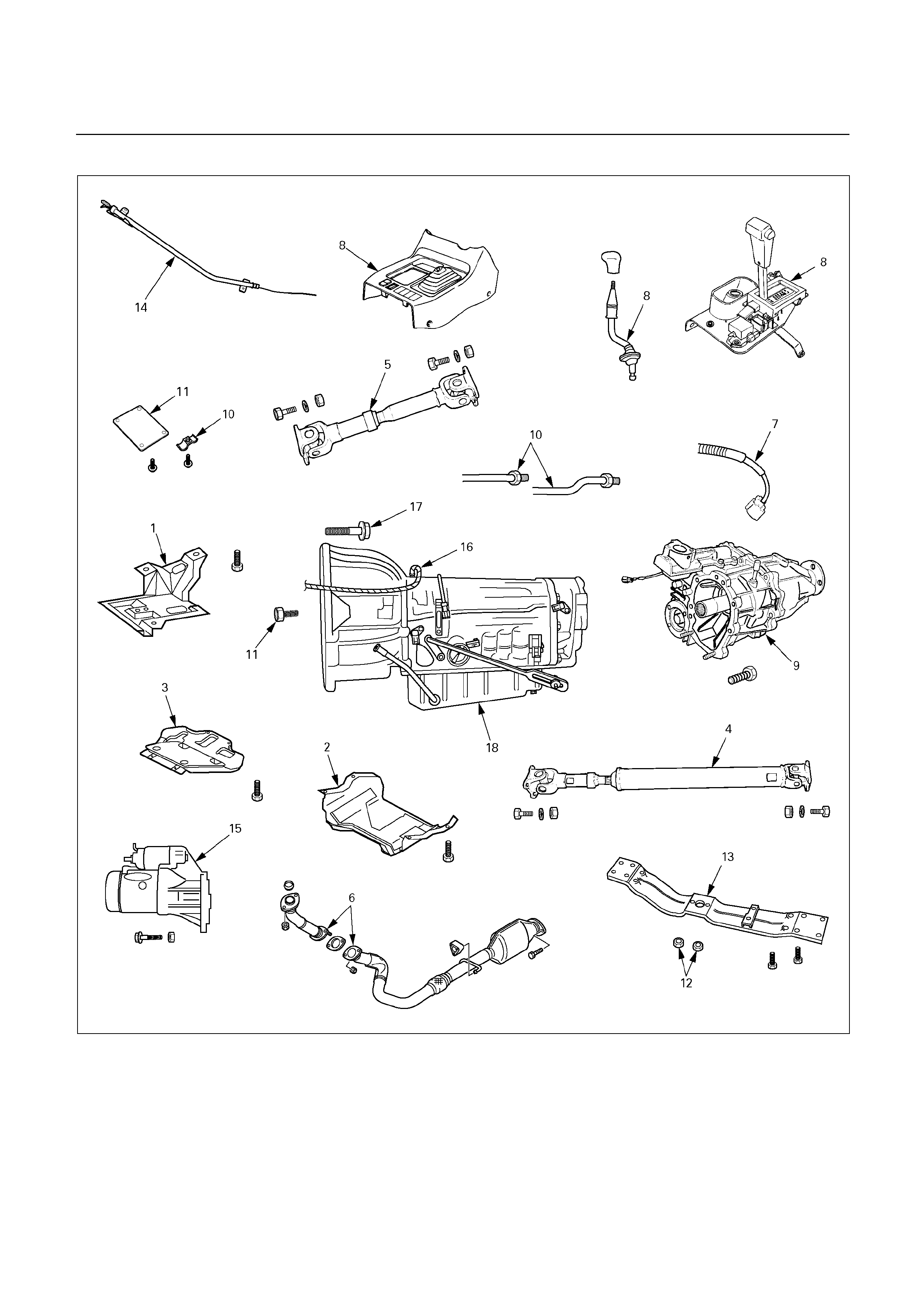
TRANSMISSION REMOVAL AND INSTALLATION (UBS)
240R200031

Removal Steps
11. Under cover and flex plate-torque
converter bolt
12. Rear mounting nut
13. 3rd crossmember
14. Oil level gauge and tube
15. Starter
16. Breather hose
17. Engine-transmission bolt
18. Transmission assembly
Installation Steps
1. Transfer protector
2. Rear sound cover
3. Front sound cover
4. Rear propeller shaft
5. Front propeller shaft
6. Exhaust pipe
7. Harness connector
8. Front console, selector lever assembly,
and transfer control lever
9. Transfer case assembly
10. ATF cooler pipe and clamp To install, follow the removal steps in reverse
order.
REMOVAL
Preparation:
Remove engine hood.
Disconnect negative (-) battery cable.
1. Transfer protector
2. Rear sound cover
3. Front sound cover
4. Rear propeller shaft
5. Front propeller shaft
NOTE:
A
pply alignment marks on the flange at both front
and rear sides.
6. Exhaust pipe
Remove the 2nd front exhaust pipe from the 1st front
exhaust pipe and exhaust silencer.
7. Harness connector
Disconnect the engine harness connectors from the
transmission side.
8. Front console, selector lever assembly, and
transfer control lever
Disconnect the transfer control lever knob.
Remove the front console.
Disconnect the harness connector.
Remove the transfer control lever.
Remove the selector lever assembly.
Disconnect the shift control rod from the selecto
r
lever assembly.
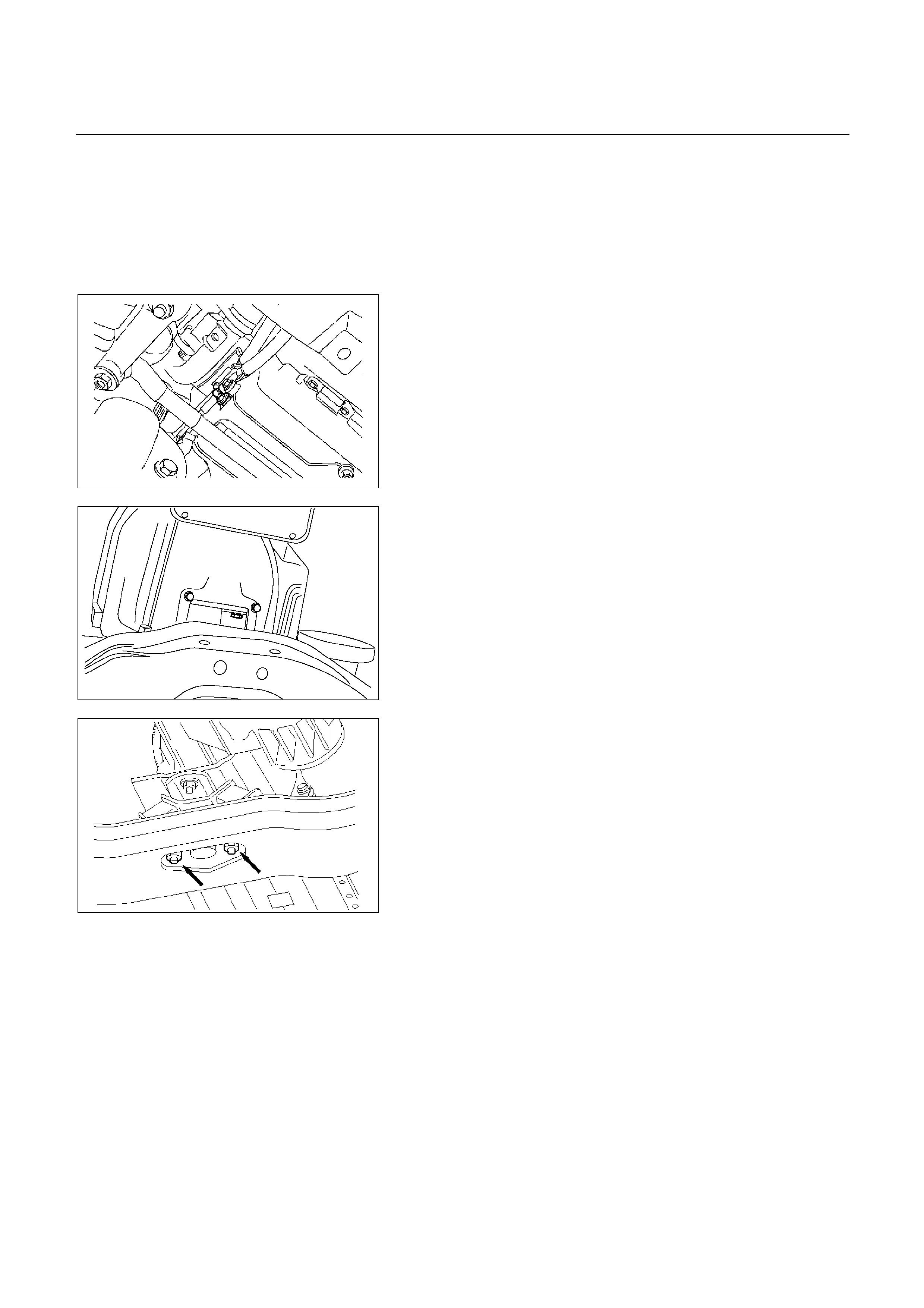
9. Transfer case assembly
Disconnect the breather hose from the transfer case.
Remove the transfer case assembly from the
transmission.
10. ATF cooler pipe and clamp
Disconnect two ATF cooler pipes from A/T side.
253RY00001
Remove oil pipe clamp from torque converter housing
side.
Loosen oil pipe clamp bolt at engine mount side.
240RY00026
11. Under cover and flex plate-torque converter bolt
Remove the under cover.
Turn the crankshaft to gain access to each bolt.
Remove the six torque coverter fixing bolts.
NOTE:
New fixing bolts should be replaced fo
r
reassembly.
022RY00001
12. Rear mounting nut
Support transmission with a jack.
Remove two rear mounting nuts from the 3rd
crossmember.
13. 3rd crossmember
14. Oil level gauge and tube
15. Starter
Remove the mounting bolts, and pull the starte
r
toward the front of the vehicle.
Lay the starter alongside the engine.
16. Breather hose
17. Engine-transmission bolt
Remove engine-transmission fixing bolts.
Disconnect the breather hose from the breather hose
2 way.

18. Transmission assembly
NOTE:
Keep the oil pan positioned down.
Be careful not to let the torque converter slide out.
INSTALLATION
To install, follow the removal steps in reverse order, noting
the following point;
1. Torque
Rear mounting to 3rd
crossmember 50 N m (5.1 kg m/37 Ib ft)
Torque converter bolt 29 N m (3.0 kg m/22 Ib ft)
ATF cooler pipe to
transmission 44 N m (4.5 kg m/33 Ib ft)
Exhaust pipe flange to
flange 43 N m (4.4 kg m/32 Ib ft)
3rd crossmember to flame 76 N m (7.8 kg m/56 Ib ft)
Front propeller shaft bolt 63 N m (6.4 kg m/46 Ib ft)
Rear propeller shaft bolt 63 N m (6.4 kg m/46 Ib ft)
Under cover bolt 6 N m (0.6 kg m/52 Ib in)
Transfer protector 37 N m (3.8 kg m/27 Ib ft)
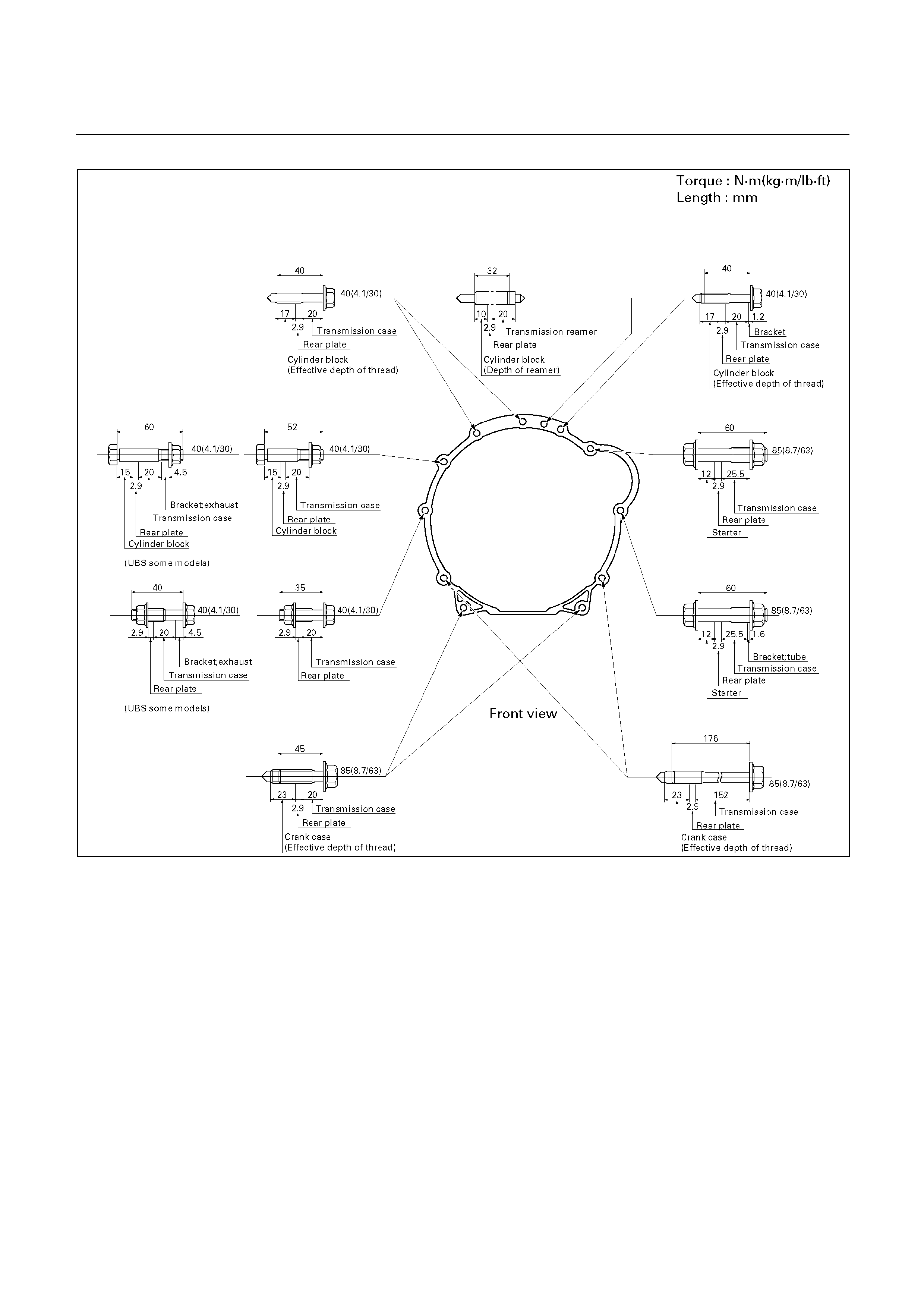
Engine-Transmission Bolt Torque
225R200006
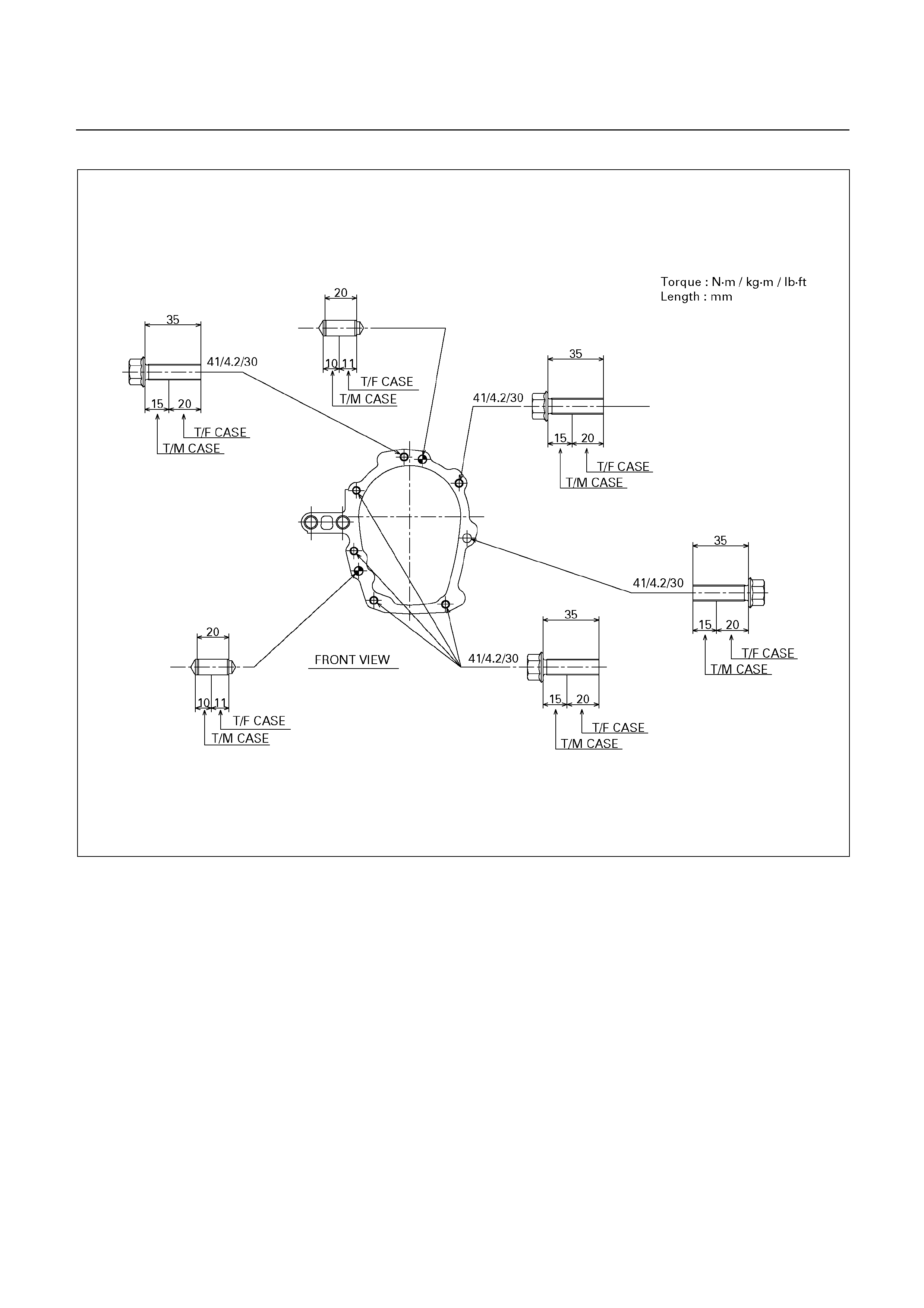
Transmission-Transfer Case Bolt Torque
260RY00001
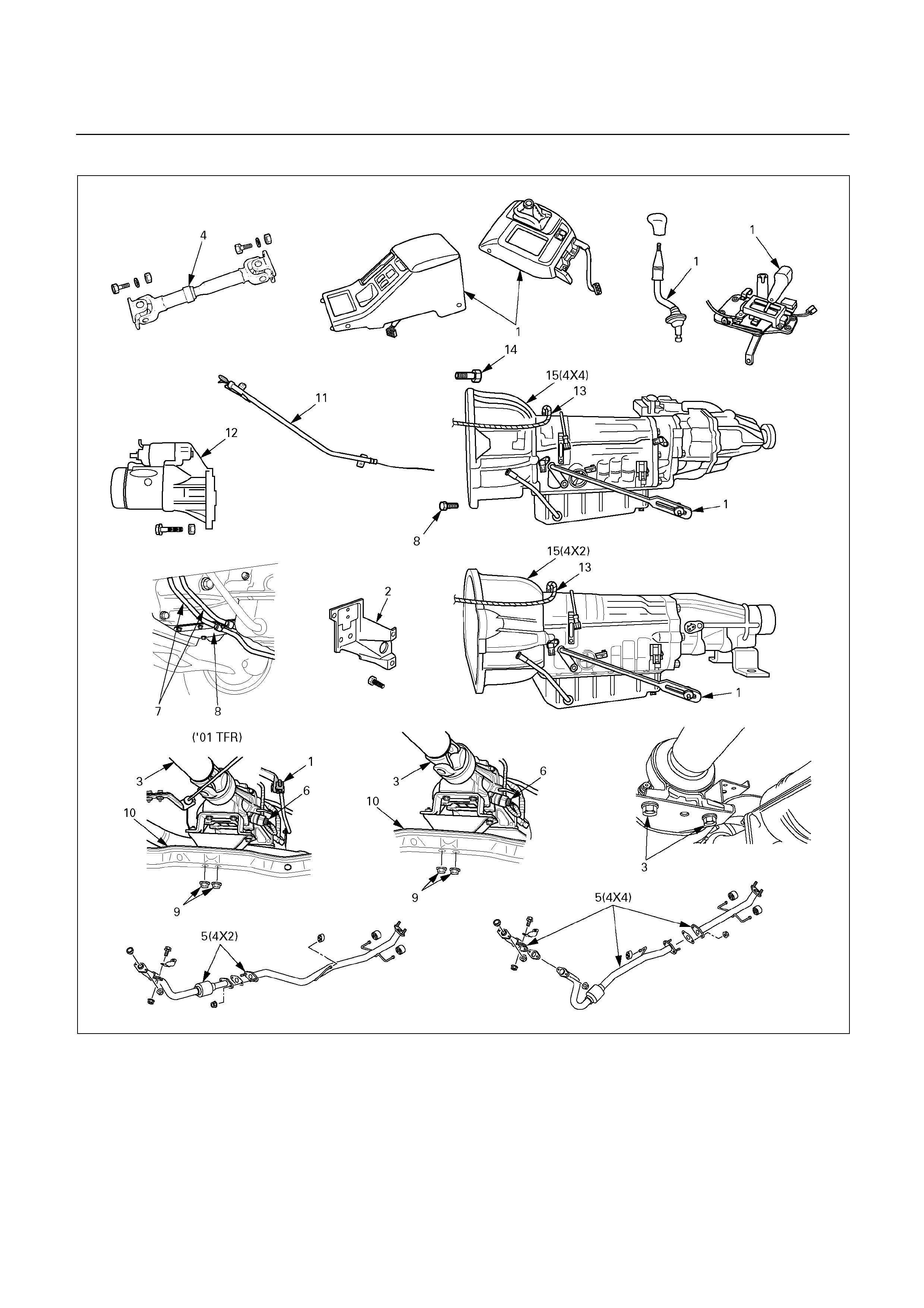
TRANSMISSION REMOVAL AND INSTALLATION (TFR/S)
240L200001
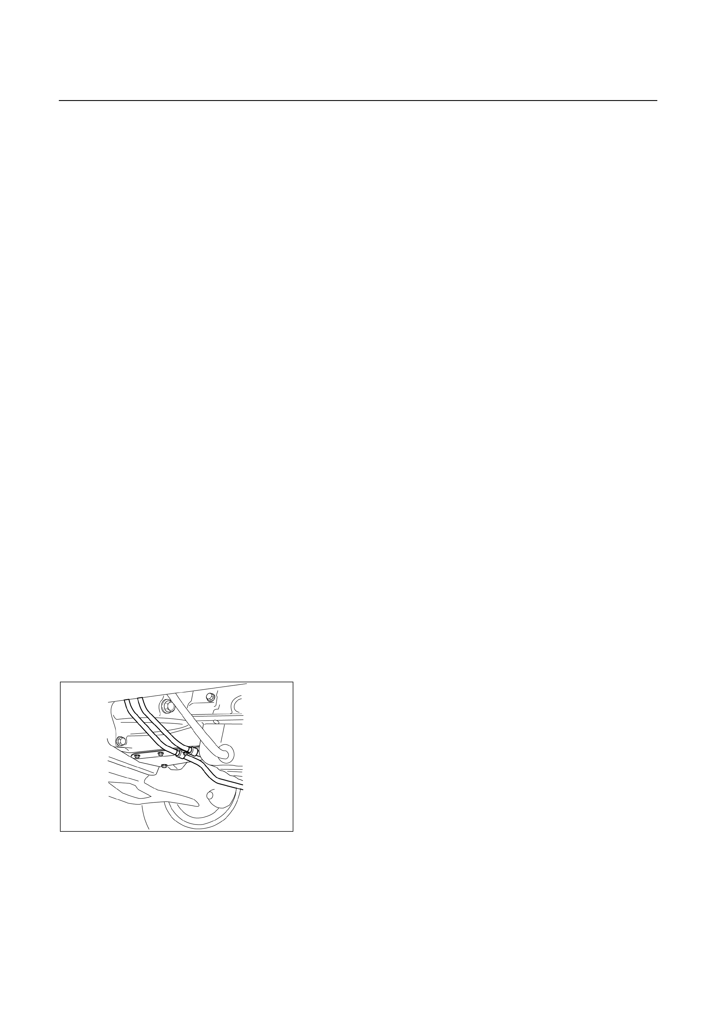
Removal Steps
9. Rear mounting nut
10. 3rd crossmember
11. Oil level gauge and tube
12. Starter
13. Breather hose
14. Engine – transmission bolt
15. Transmission assembly
1. Center console, rear console, select
lever assembly, and transfer control
lever (4 4)
2. Transfer protector (4 4)
3. Rear propeller shaft
4. Front propeller shaft (4 4)
5. Exhaust pipe
6. Harness connector
7. ATF cooler pipe and clamp
8. Under cover and flex plate-torque
converter bolt
Installation Steps
To install, follow the removal steps in reverse
order.
REMOVAL
Preparation:
Remove engine hood.
Disconnect negative (-) battery cable.
1. Center console, rear console, select leve
r
assembly, and transfer control lever (4 4)
Disconnect the control rod from the select leve
r
assembly.
2. Transfer protector (4 4)
3. Rear propeller shaft
Disconnect the center bearing bracket, and remove
rear propeller shaft.
4. Front propeller shaft (4 4)
5. Exhaust pipe
6. Harness connector
Disconnect the engine harness connectors from the
transmission side.
253LV001
7. ATF cooler pipe and clamp
Disconnect two ATF cooler pipes from A/T side.
Remove oil pipe clamp from the under cover and
torque converter housing side.

240RW037
8. Under cover and flex plate-torque converter bolt
Remove the under cover.
Turn the crankshaft to gain access to each bolt.
Remove the six torque converter fixing bolts.
NOTE:
New fixing bolts should be replaced fo
r
reassembly.
9. Rear mounting nut
Support transmission with a jack.
Remove two rear mounting nuts from the 3rd
crossmember.
If necessary, remove the rear mounting from the
transmission.
10. 3rd crossmember
11. Oil level dipstick and tube
12. Starter
Remove the mounting bolts, and pull the starte
r
toward the front of the vehicle.
Lay the starter alongside the engine.
13. Breather hose
14. Engine-transmission bolt
Remove engine-transmission fixing bolts.
15. Transmission assembly
If necessary, remove the transfer case from the
transmission assembly. (44)
Refer to Section 4 “DRIVE LINE/AXLE” for removal
and installation.
NOTE:
Keep the oil pan positioned down.
Be careful not to let the torque converter slide out.

INSTALLATION
To install, follow the removal steps in the reverse order,
noting the following points;
1. Torque
Rear mounting to
crossmember 41 N m (4.2 kg m/30 Ib ft)
Rear mounting to
transmission 41 N m (4.2 kg m/30 Ib ft)
Torque converter bolt 29 N m (3.0 kg m/22 Ib ft)
ATF cooler pipe to
elbow 44 N m (4.5 kg m/33 Ib ft)
Exhaust pipe flange to
flange 43 N m (4.4 kg m/32 Ib ft)
Exhaust pipe to exhaust
manifold 67 N m (6.8 kg m/4.9 Ib ft)
Rear propeller shaft bolt 63 N m (6.4 kg m/46 Ib ft)
Center bearing retainer
bolt 69 N m (7.0 kg m/51 Ib ft)
Front propeller shaft bolt 63 N m (6.4 kg m/46 Ib ft)
3rd crossmember bolt 76 N m (7.8 kg m/56 Ib ft)
Under cover bolt 6 N m (0.6 kg m/52 Ib in)
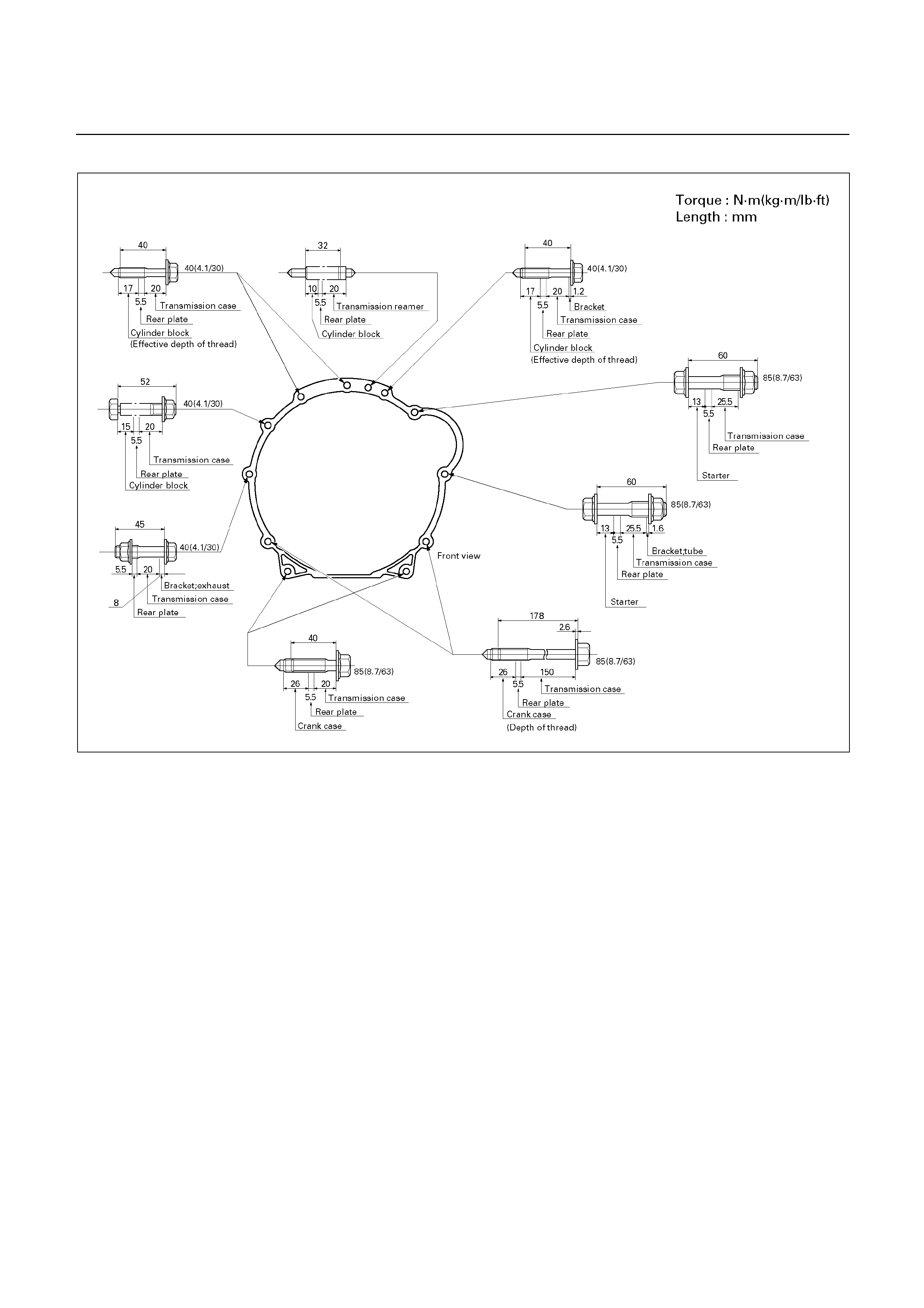
Engine – Transmission Bolt Torque
E07L200003
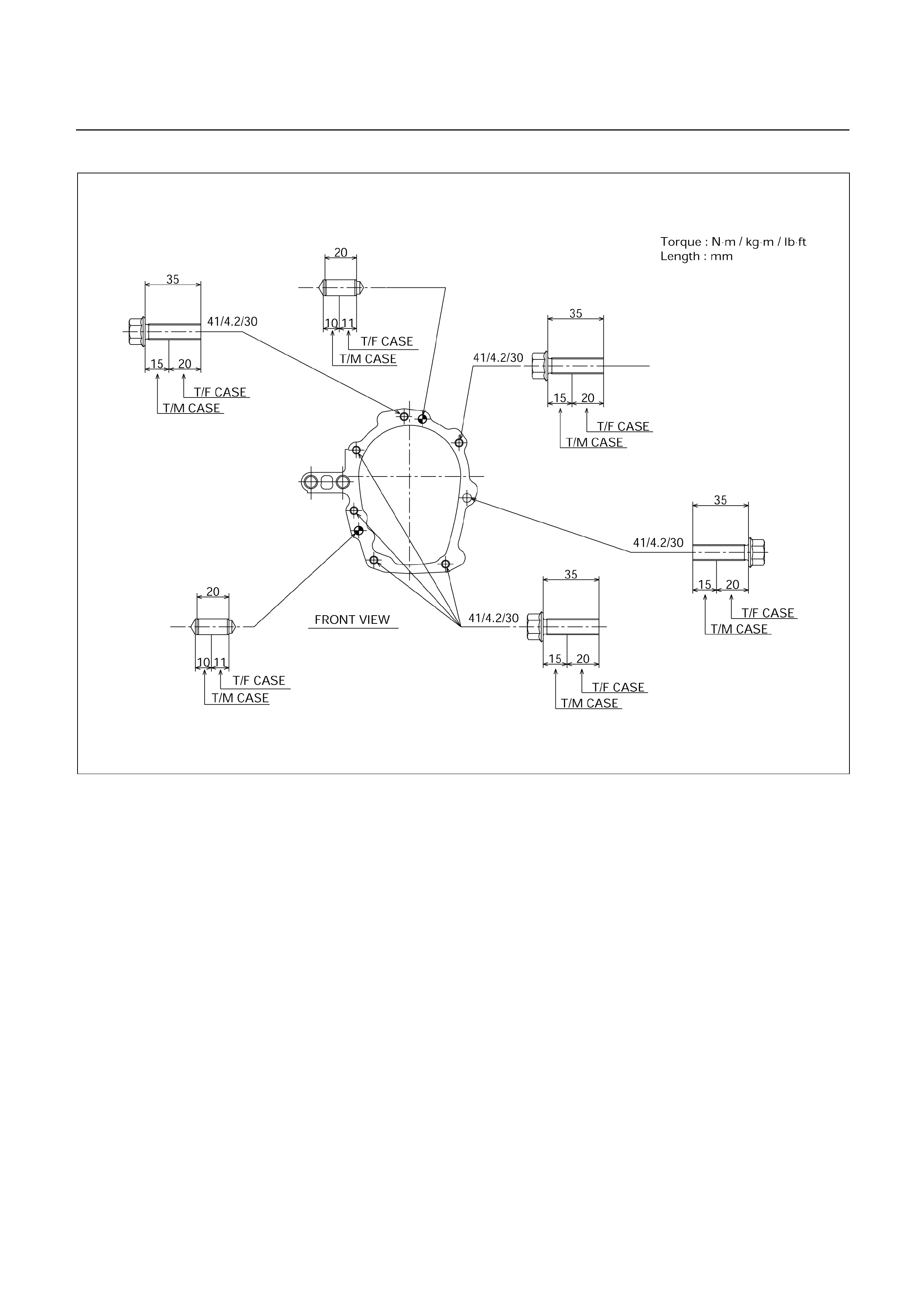
Transmission-Transfer Case Bolt Torque (Reference)
260RY00001

UNIT REPAIR
MAJOR COMPONENTS
Disassembly, inspection and reassembly of each
component group is indicated in the following chapter.
Before reassembly, make sure, again, that all component
groups are assembled correctly.
If something wrong is found in a certain component group
during assembly, inspect and repair this group
immediately.
GENERAL ASSEMBLY NOTES:
1. The automatic transmission is composed of highl
y
precision-finished parts, necessitating careful inspection
before assembly because even a small nick could cause
fluid leakage or affect performance.
2. Before assembling new clutch discs and brake bands,
soak them in automatic transmission fluid for at least thirt
y
minutes.
3. Apply automatic transmission fluid on the sliding or rotating
surfaces of parts before assembly.
4. Use petroleum jelly to keep small parts in their palces.
5. Do not use adhesive cements on gaskets and simila
r
parts.
6. When assembling the transmission, be sure to use new
gaskets and O-rings.
7. Dry all parts with compressed air – never use shop rags.
8. Be sure to install the thrust bearings and races in the
correct direction and position.
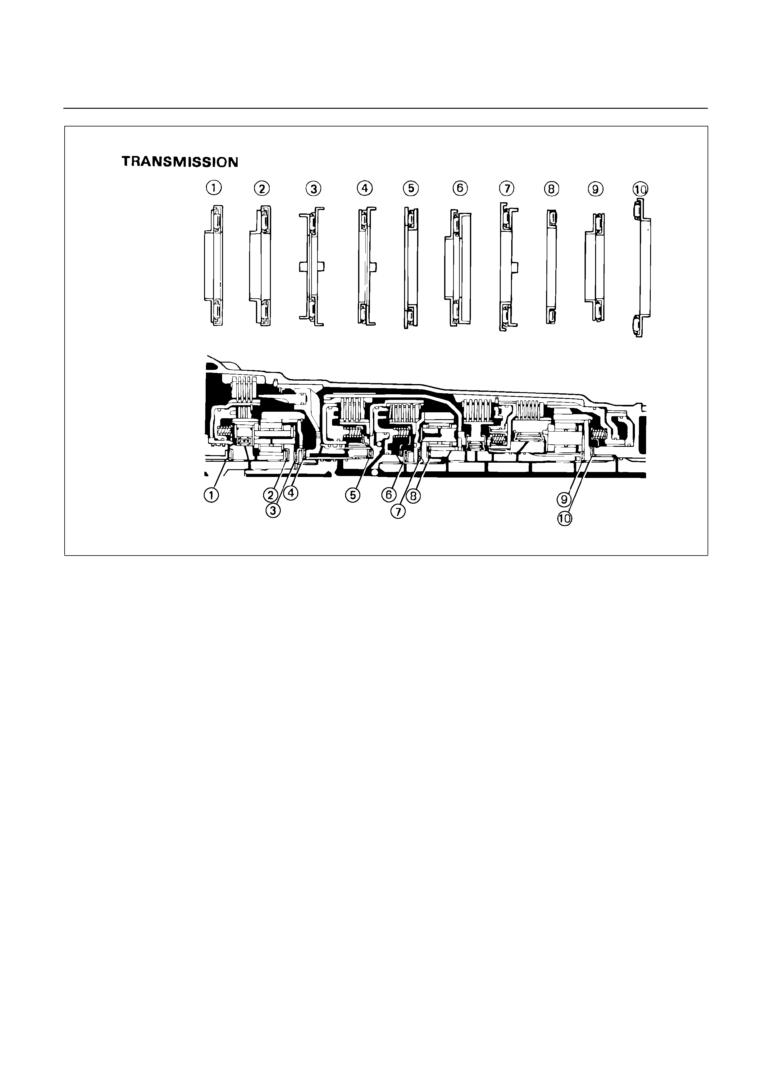
240RY00022
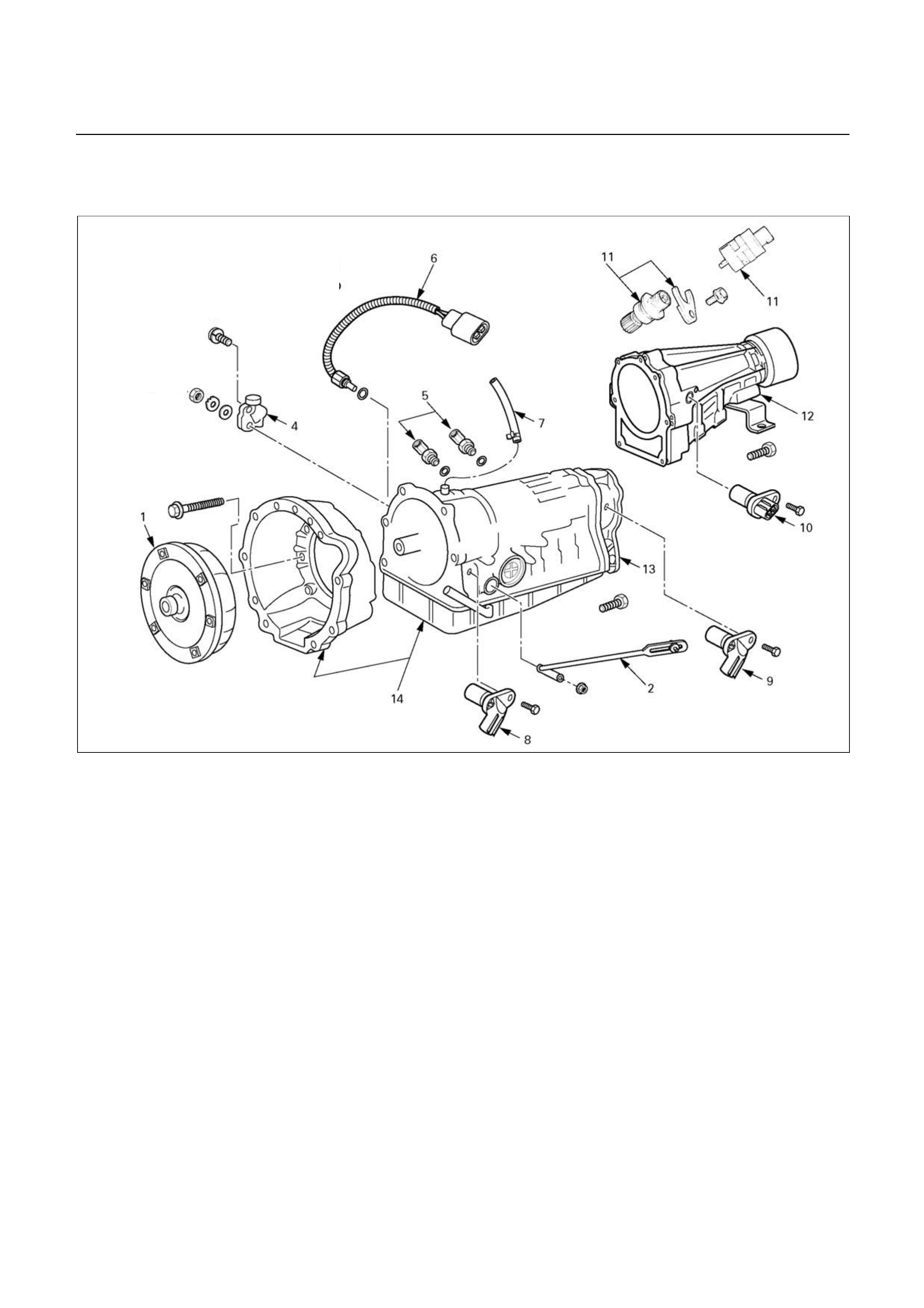
DISASSEMBLY OF MAJOR
COMPONENTS (1)
240R200036
Disassembly steps
1. Torque converter
2. Transmission control rod and select
lever (UBS and TFR/S)
4. Neutral start switch
5. Elbow
6. Oil temperature sensor
7. Breather hose
8. Input revolution sensor
9. Output revolution sensor (4x4)
10. Output revolution sensor (4x2)
11. Speedometer sensor, speedometer
driven gear and plate (4
x2)
12. Extension housing (4
x2)
13. Adapter housing (4 x4)
14. Transmission assembly
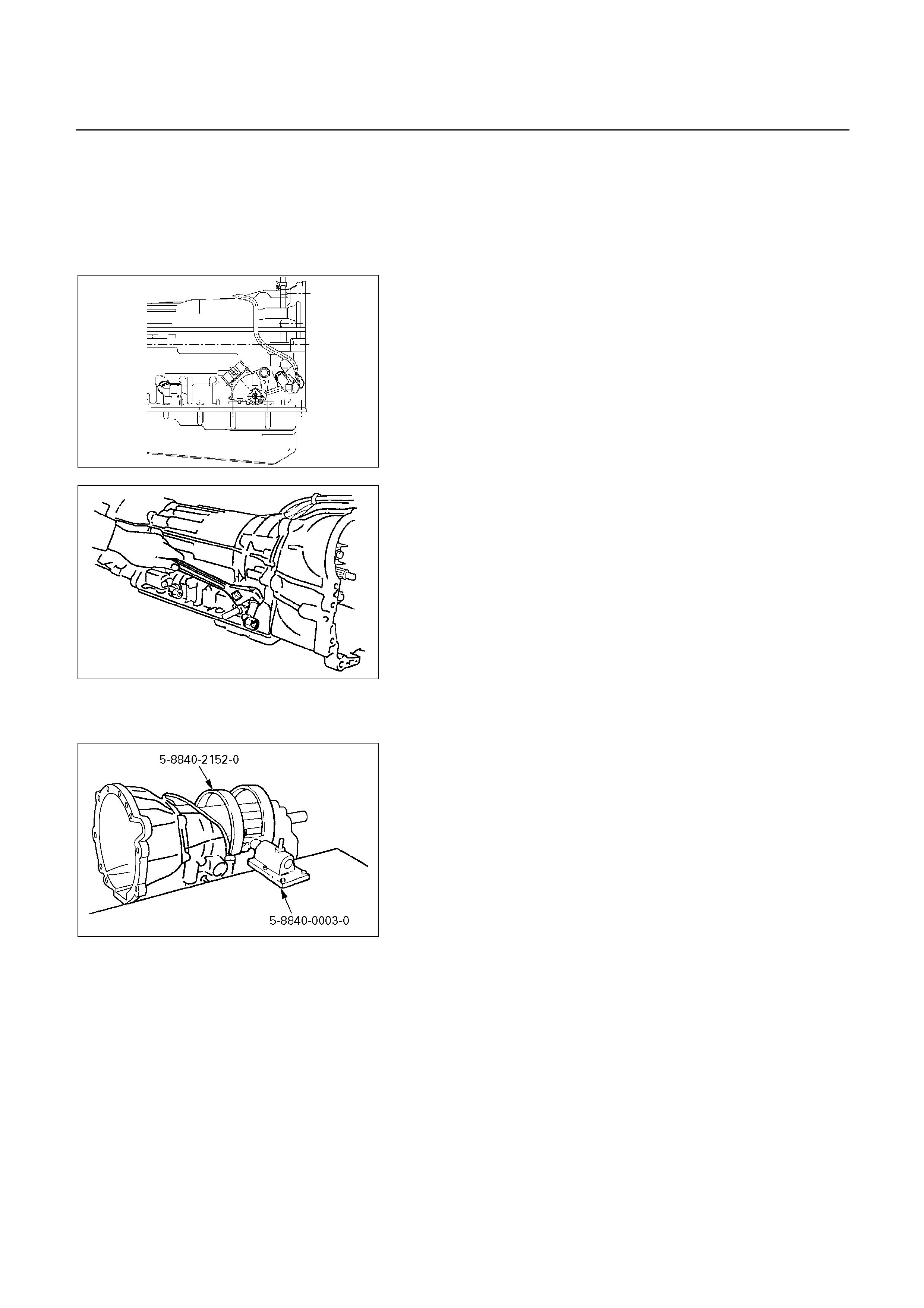
Disassembly steps
1. Torque converter
2. Transmission control rod and select lever (UBS and
TFR/S)
3. Not applicable for Australian vehicles
249RW003
4. Neutral start switch
Unstake the lock washer.
Remove the nut and bolts, and then remove the neutral
start switch.
Remove the lock washer and grommet.
240RY00001
5. Elbow
Remove two elbows from transmission case.
6. Oil temperature sensor
7. Breather hose
8. Input revolution sensor
9. Output revolution sensor (4 4)
10. Output revolution sensor (4 2)
11. Speedometer sensor, speedometer driven gear and
plate (4 ×
××
× 2)
12. Extension housing (4 ×
××
× 2)
13. Adapter housing (4 ×
××
× 4)
240R200021
14. Transmission assembly
Install special tool to the transmission unit.
Holding fixture: 5-8840-2152-0 (J-37227)
Fixture base: 5-8840-0003-0 (J-3289-20)

REASSEMBLY OF MAJOR
COMPONENTS (1)
240R200035
Reassembly steps
1. Transmission assembly
2. Extension housing (4 2)
3. Speedometer driven gear, plate, and
speedometer sensor (4 2)
4. Adapter housing (4 4)
5. Neutral start switch
6. Oil temperature sensor
7. Elbow
8. Transmission control rod and select
lever (UBS and TFR/S)
9. Transmission control rod and select
lever - Not applicable for Australian vehicles
10. Output revolution sensor (4 2)
11. Output revolution sensor (4 4)
12. Input revolution sensor
13. Breather hose
14. Torque converter
Reassembly steps
1. Transmission assembly
2. Extension housing (4 2)
Install a new gasket and the extension housing to the
transmission case.
Torque: 51 N m (5.2 kg m/38 Ib ft)

3. Speedometer driven gear, plate, and speedomete
r
sensor (4 2)
Torque:
Plate bolt – 15 N m (1.5 kg m/11 Ib ft)
Speedometer sensor – 25 N m (2.5 kg m/18 Ib ft)
241RY00020
4. Adapter housing (4 4)
Remove any gasket material on the contacting surfaces
of the adapter housing and transmission case.
Apply liquid gasket (TB1281-B or its equivalent) (1) and
install the apply gaskets (2) to the adapter housing as
shown in the figure.
Install the adapter housing to the transmission case.
Torque: 34 N m (3.5 kg m/25 Ib ft)
249L100003
5. Neutral start switch
Using the transmission select lever, fully turn the
manual valve lever shaft back and return two notches.
It is now in neutral.
Insert the neutral start switch onto the manual valve
lever shaft and temporarily tighten the adjusting bolt.
Install the lock washer and nut.
Torque: 7 N m (0.7 kg m/61 Ib in)
Align the neutral standard line and the switch groove
and tighten the adjusting bolt.
Torque: 13 N m (1.3 kg m/113 Ib in)
Bend the tabs of the lock washer.
NOTE:
Bend at least two of the lock washer tabs.
249L100001
6. Oil temperature sensor
Install the oil temperature sensor to the transmission
case.
Torque: 15 N m (1.5 kg m/11 Ib ft)
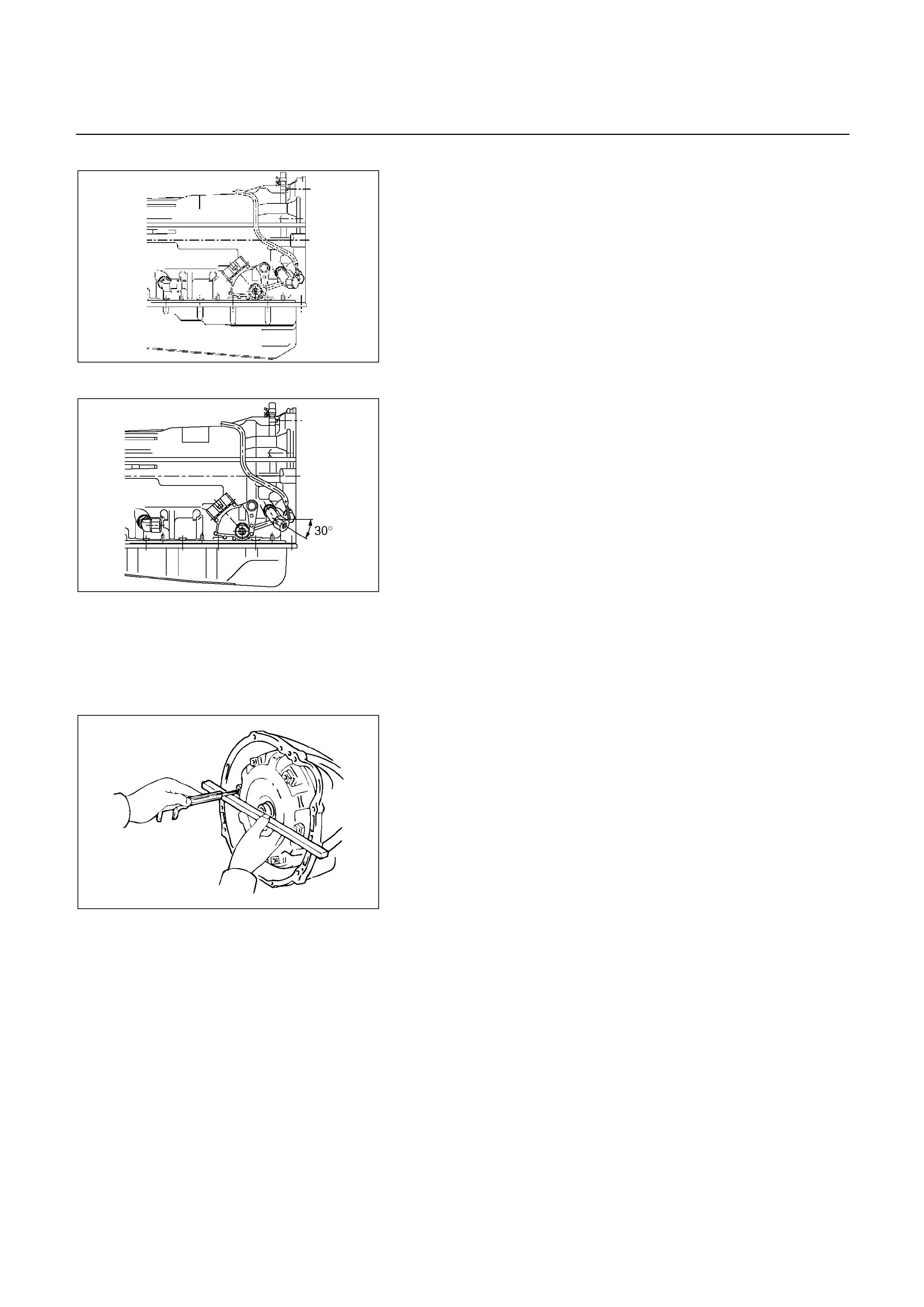
UBS
249RW003
TF
249R200009
7. Elbow
Coat new O-rings with ATF, install them to the two
elbows.
Install the two elbows as shown in the figure.
Torque: 29 N m (3.0 kg m/22 Ib ft)
8. Transmission control rod and select lever (UBS and
TFR/S)
9. N/A Australian vehicles
Torque: 29 N m (3.0 kg m/22 Ib ft)
10. Output revolution sensor (4 2)
11. Output revolution sensor (4 4)
12. Input revolution sensor
13. Breather hose
240RY00005
14. Torque converter
Using calipers and a straight edge, measure from the
installed surface of the transmission housing.
Correct distance: 67 mm (2.64 in) or more
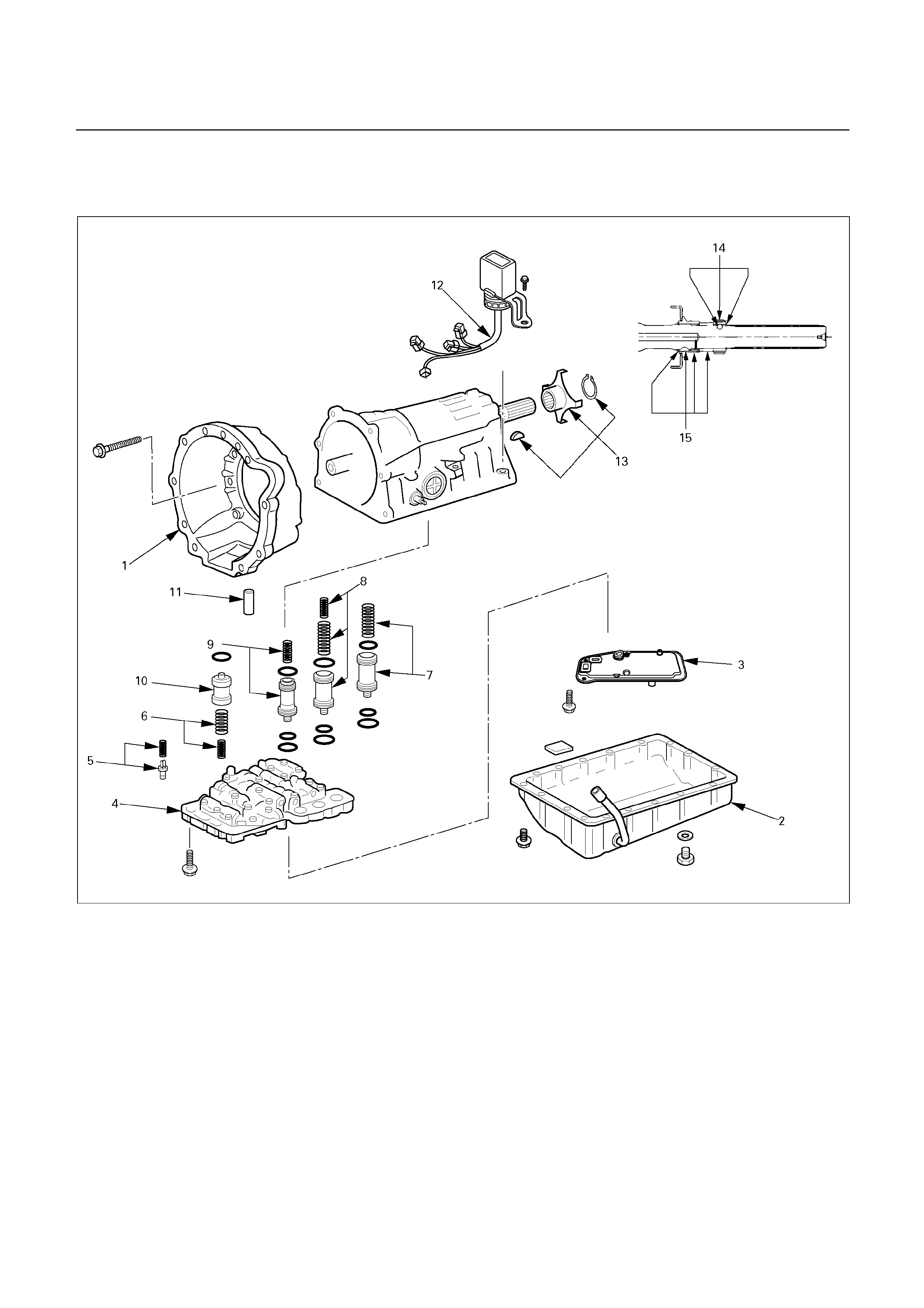
DISASSEMBLY OF MAJOR
COMPONENTS (2)
242R200006
Disassembly steps
1. Converter housing
2. Oil pan
3. Oil strainer assembly
4. Valve body
5. Check valve, spring
6. Spring
7. Accumulator piston (B-2)
8. Accumulator piston (C-2)
9. Accumulator piston (B-0)
10. Accumulator piston (C-0)
11. Second brake drum gasket
12. Solenoid wiring
13. Snap ring, rotor, key (4 4)
14. Snap ring, speedometer sensor drive
gear, ball (4 2)
15. Spacer, rotor, key, snap ring (4 2)
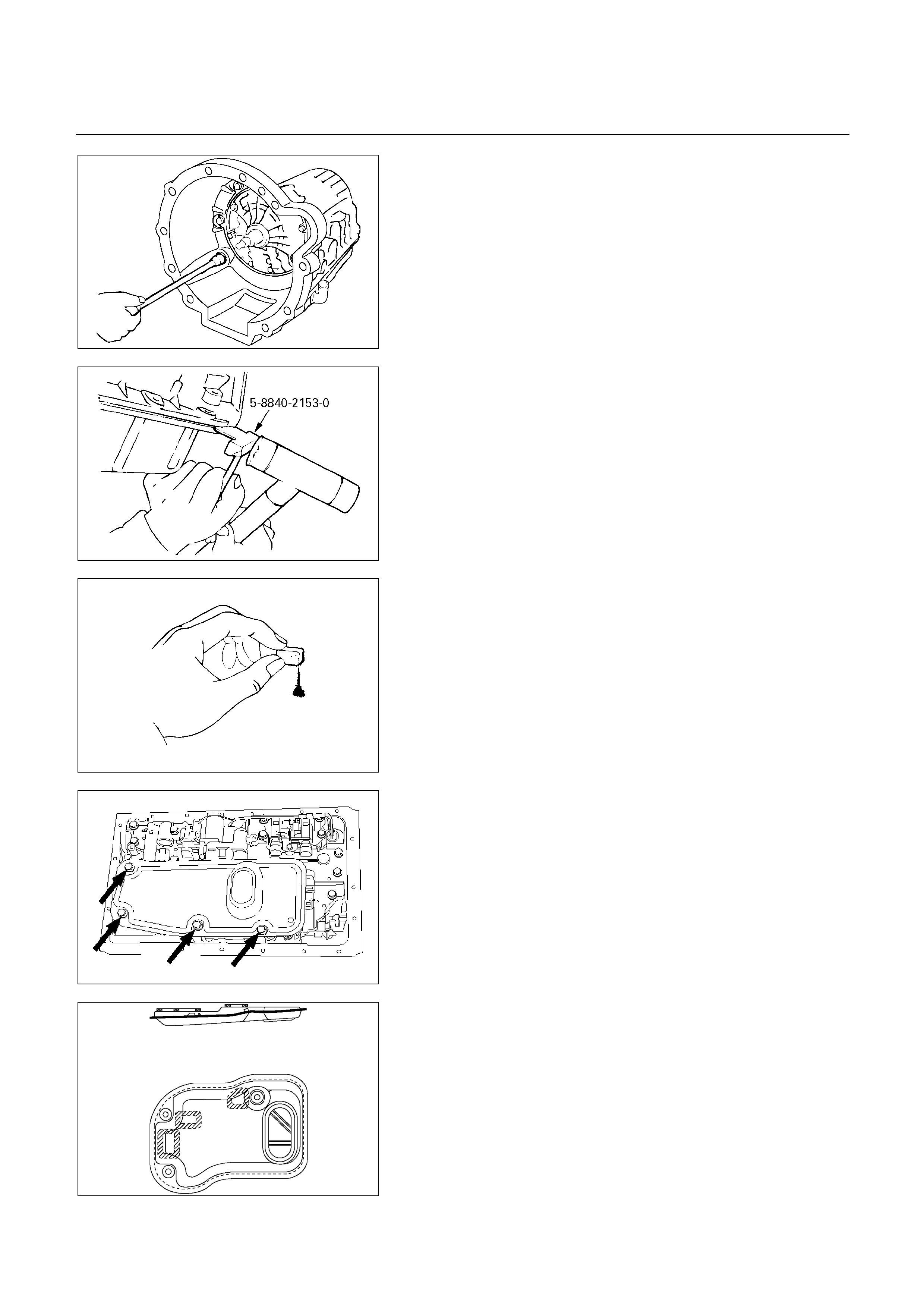
240R200022
Disassembly steps
1. Converter housing
Remove the six bolts.
Remove the converter housing.
240RY00007
2. Oil pan
NOTE:
Do not turn over the transmission as this will
contaminate the valve body with foreign materials
in the bottom of the oil pan.
Remove the nineteen bolts.
Remove oil pan by lifting the transmission case.
Seal cutter: 5-8840-2153-0 (J-37228)
240RY00008
Examine particles in oil pan
Remove the magnet and use it to collect any steel
chips.
Look carefully at the chips and particles in the oil pan
and on the magnet to anticipate what type of wear you
will find in the transmission:
Steel (magnetic) …… bearing, gear and clutch plate
wear
Brass (non-magnetic)… bushing wear
244RY00003
3. Oil strainer assembly
Remove four bolts holding the oil strainer (UBS and
TFR/S).
244L100001
Remove three bolts holding the oil strainer (’01 TFR).
NOTE:
When reassembling components, install a new oil
strainer assembly.
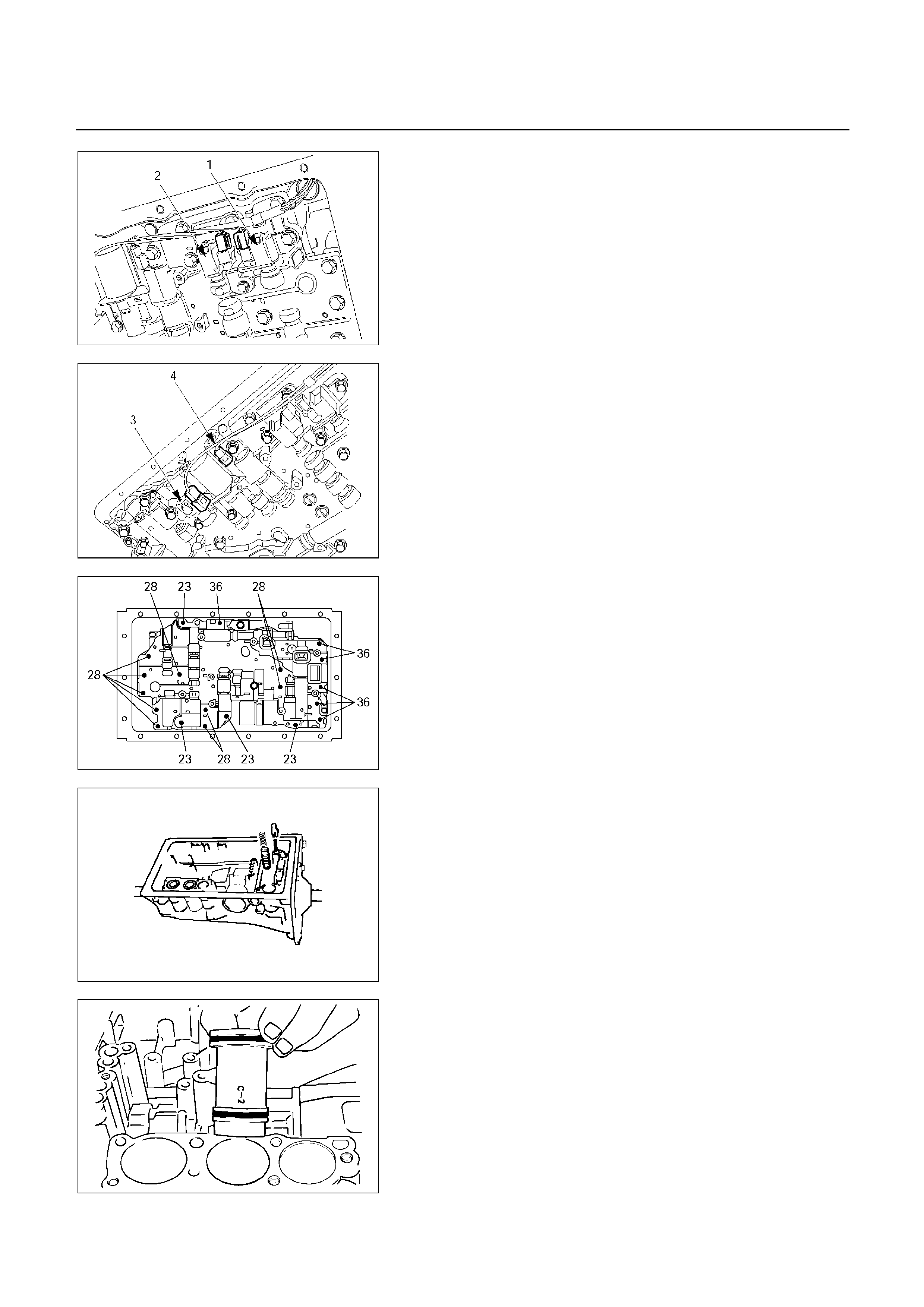
249RY00011
4. Valve body
Disconnect the connectors from the solenoid S1 (1), S2
(2), lock-up solenoid (3) and pressure control solenoid
(4).
249RY00012
244RY00017
Remove the twenty bolts from valve body.
240RY00028
5. Check valve, spring
6. Spring
Remove the check valve and spring.
Remove two springs from C-0 accumulator piston.
240RY00010
7. Accumulator piston (B-2)
8. Accumulator piston (C-2)
Remove accumulator pistons and springs from
transmission case.

240RY00011
9. Accumulator piston (B-0)
Applying compressed air to the oil hole, remove the B-0
accumulator piston and spring.
240RY00012
10. Accumulator piston (C-0)
Remove the C-0 accumulator piston.
11. Second brake drum gasket
12. Solenoid wiring
Turn over transmission, remove the solenoid wiring
stopper plate from the case.
Pull the wiring out of the transmission case.
247R200002
13. Snap ring, rotor, key (4 4)
Remove the snap ring from the output shaft.
Remove the rotor and key.
247L100001
14. Snap ring, speedometer sensor drive gear, ball
(4 2)
Remove the snap ring from the output shaft.
Remove the speedometer sensor drive gear, and ball.
15. Spacer, rotor, key, snap ring (4 2)
Remove the spacer, rotor and key.
Remove the snap ring from the output shaft.
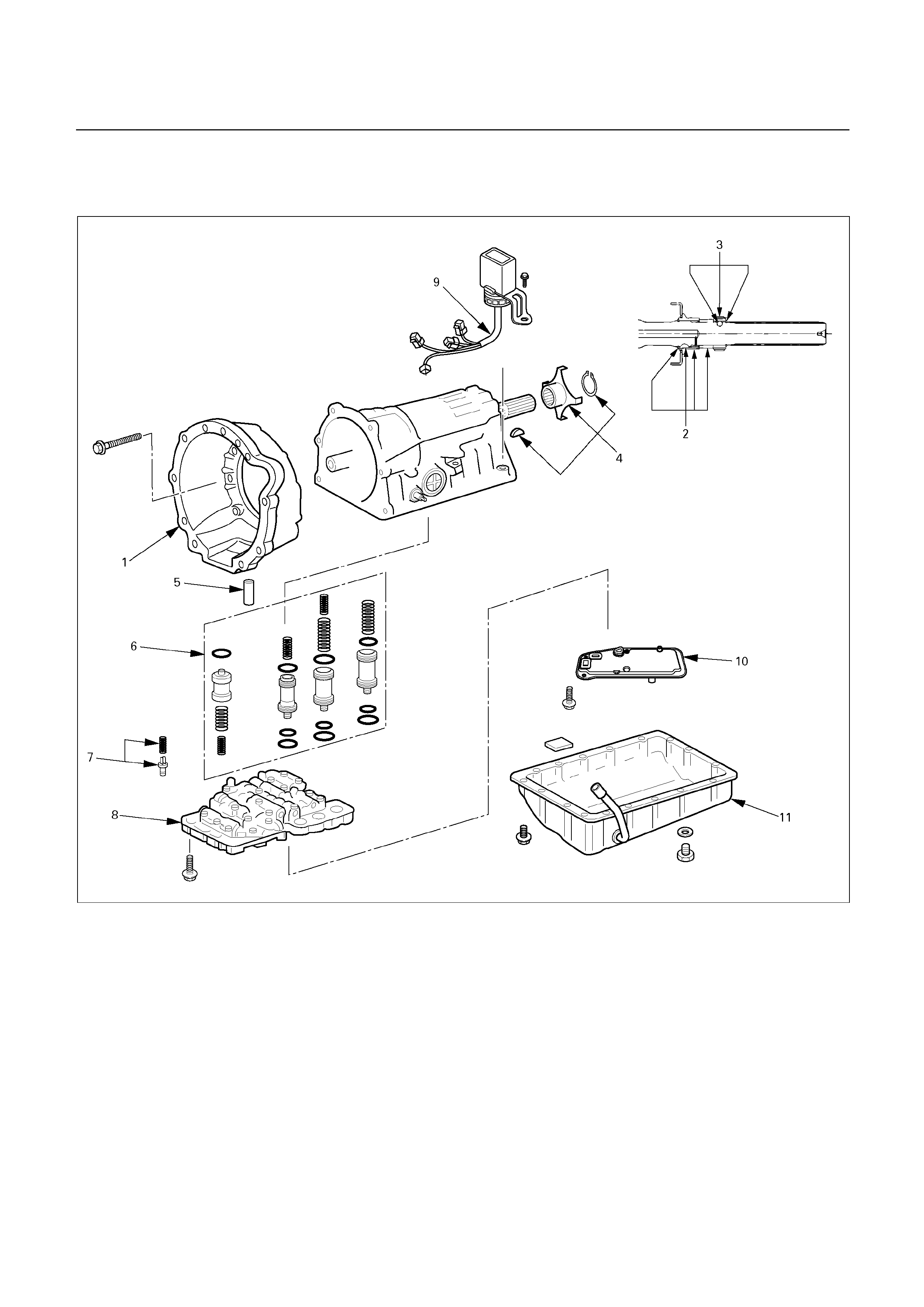
REASSEMBLY OF MAJOR
COMPONENTS (2)
242R200007
Reassembly steps
1. Converter housing
2. Snap ring, key, rotor (4 2)
3. Spacer, ball, speedometer sensor drive
gear, snap ring (4 2)
4. Key, rotor, snap ring (4 4)
5. Second brake drum gasket
6. Accumulator piston
7. Check valve, spring
8. Valve body
9. Solenoid wiring
10. Oil strainer assembly
11. Oil pan
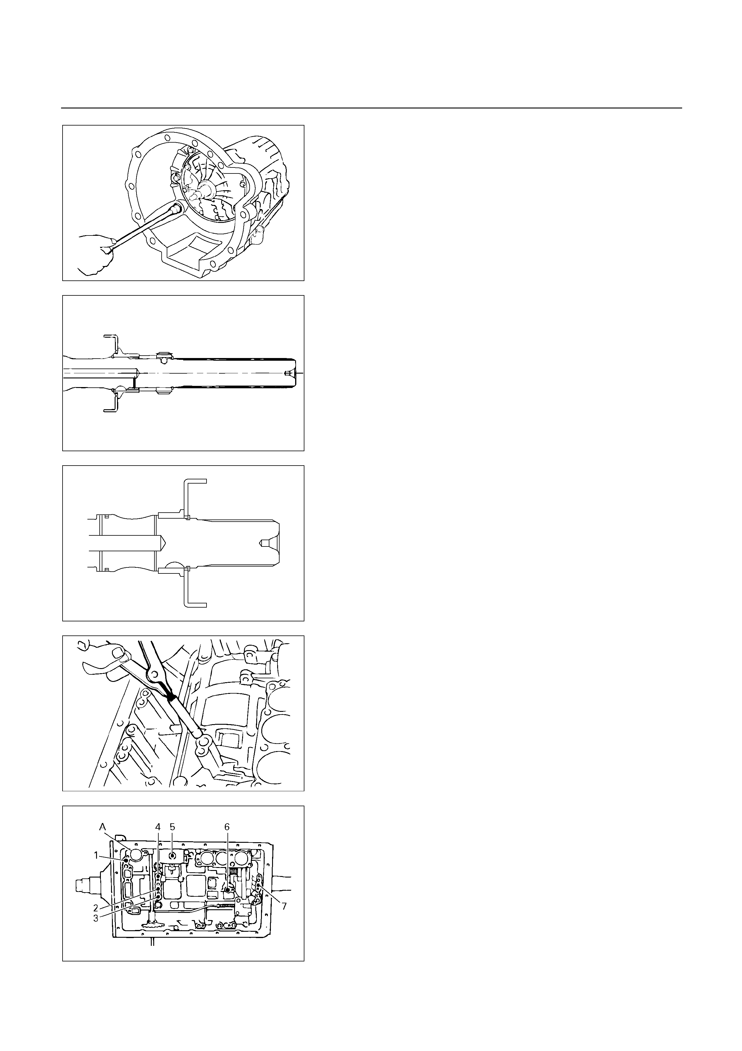
240R200022
Reassembly steps
1. Converter housing
Torque:
M10 - 34 N m (3.5 kg m/25 Ib ft)
M12 - 57 N m (5.8 kg m/42 Ib ft)
247L100001
2. Snap ring, key, rotor (4 2)
Install the snap ring to the output shaft.
Install the key and rotor.
3. Spacer, ball, speedometer sensor drive gear, snap
ring (4 2)
Install the spacer, ball and speedometer sensor drive
gear.
Install the snap ring to the output shaft.
247R200002
4. Key, rotor, snap ring (4 4)
Install the key and rotor.
Install the snap ring to the output shaft.
240RY00013
5. Second brake drum gasket
Install a new second brake drum gasket to the
transmission case.
Individual piston operation inspection
Check for the sound of operation while injecting
compressed air into the oil hole indicated in the figure.
240RY00014
1: OD direct clutch
2: Direct clutch
3: Forward clutch
4: OD brake
5: Second coast brake
6: Second brake
7: First and reverse brake
A
: C-0 Accumulator piston
hole

NOTE:
When inspecting the direct clutch, check with the
C-0 accumulator piston hole closed. If there is no
noise, disassemble and check the condition of the
parts.
240RY00027
6. Accumulator piston
Coat the O-ring with ATF and install it to the piston.
Install the three springs and four accumulator pistons to
the bore as shown in th figure.
Piston Outer diameter Height
B-2 36.8 mm (1.449 in) 62.5 mm (2.461 in)
C-2 36.8 mm (1.449 in) 56.6 mm (2.228 in)
B-0 31.8 mm (1.252 in) 52.0 mm (2.047 in)
C-0 29.8 mm (1.173 in) 44.0 mm (1.732 in)
UBS
Spring Free length Outer diameter
B-2 75.8 mm (2.984 in) 20.1 mm (0.791 in)
C-2 (Outer) 64.0 mm (2.520 in) 20.2 mm (0.795 in)
C-2 (Inner) 42.1 mm (1.658 in) 14.7 mm (0.579 in)
B-0 63.6 mm (2.504 in) 16.0 mm (0.630 in)
C-0 (Outer) 74.6 mm (2.937 in) 20.9 mm (0.823 in)
C-0 (Inner) 46.0 mm (1.811 in) 14.0 mm (0.551 in)
TFR/S
Spring Free length Outer diameter
B-2 73.4 mm (2.890 in) 19.9 mm (0.783 in)
C-2 (Outer) 70.3 mm (2.768 in) 20.2 mm (0.795 in)
C-2 (Inner) 42.1 mm (1.658 in) 14.7 mm (0.579 in)
B-0 62.0 mm (2.441 in) 16.0 mm (0.630 in)
C-0 (Outer) 74.6 mm (2.937 in) 20.9 mm (0.823 in)
C-0 (Inner) 46.0 mm (1.811 in) 14.0 mm (0.551 in)
240RY00029
240RY00010
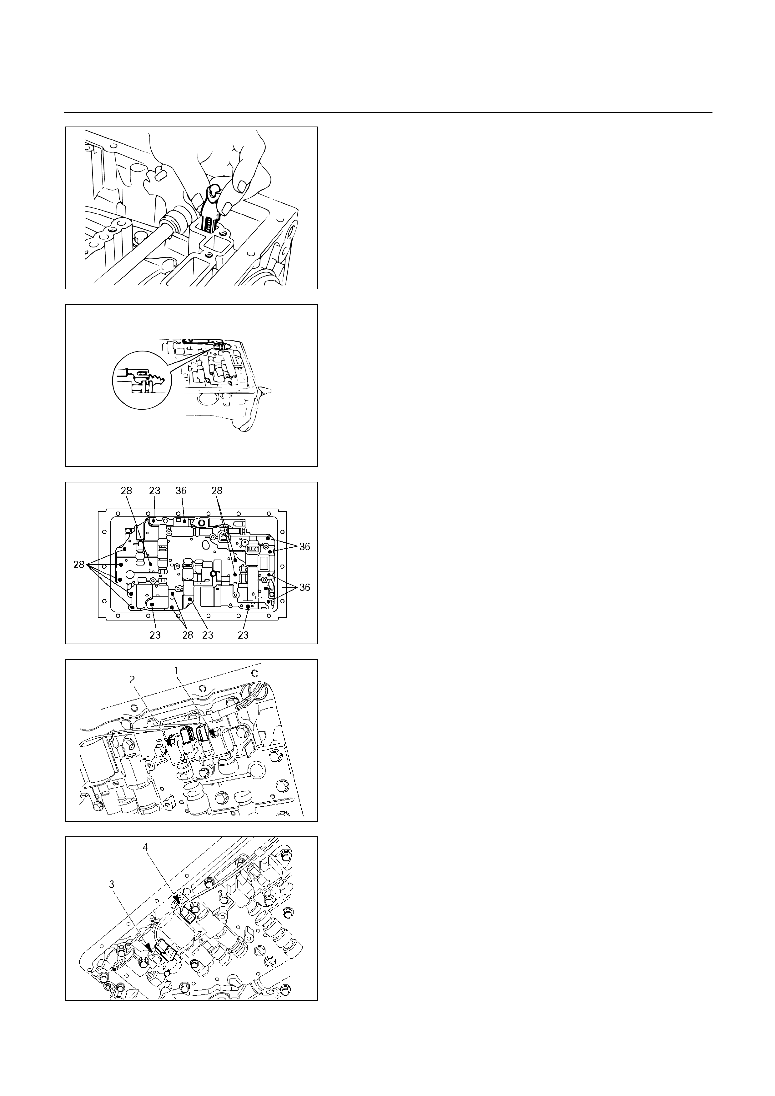
240RY00016
7. Check valve, spring
Install new check valve and spring.
240RY00017
8. Valve body
Align the groove of the manual valve to the pin of the
lever.
244RY00017
Install the twenty bolts.
NOTE:
Each bolt length (mm) is indicated in the figure.
Torque: 10 N m (1.0 kg m/87 Ib in)
249RY00011
9. Solenoid wiring
Coat a new O-ring with ATF, and install it to the
solenoid wiring.
Insert the solenoid wiring to the case and install the
stopper plate.
Connect the connectors to the solenoid S1 (1), S2 (2),
lock-up solenoid (3), and pressure control solenoid (4).
249RY00012
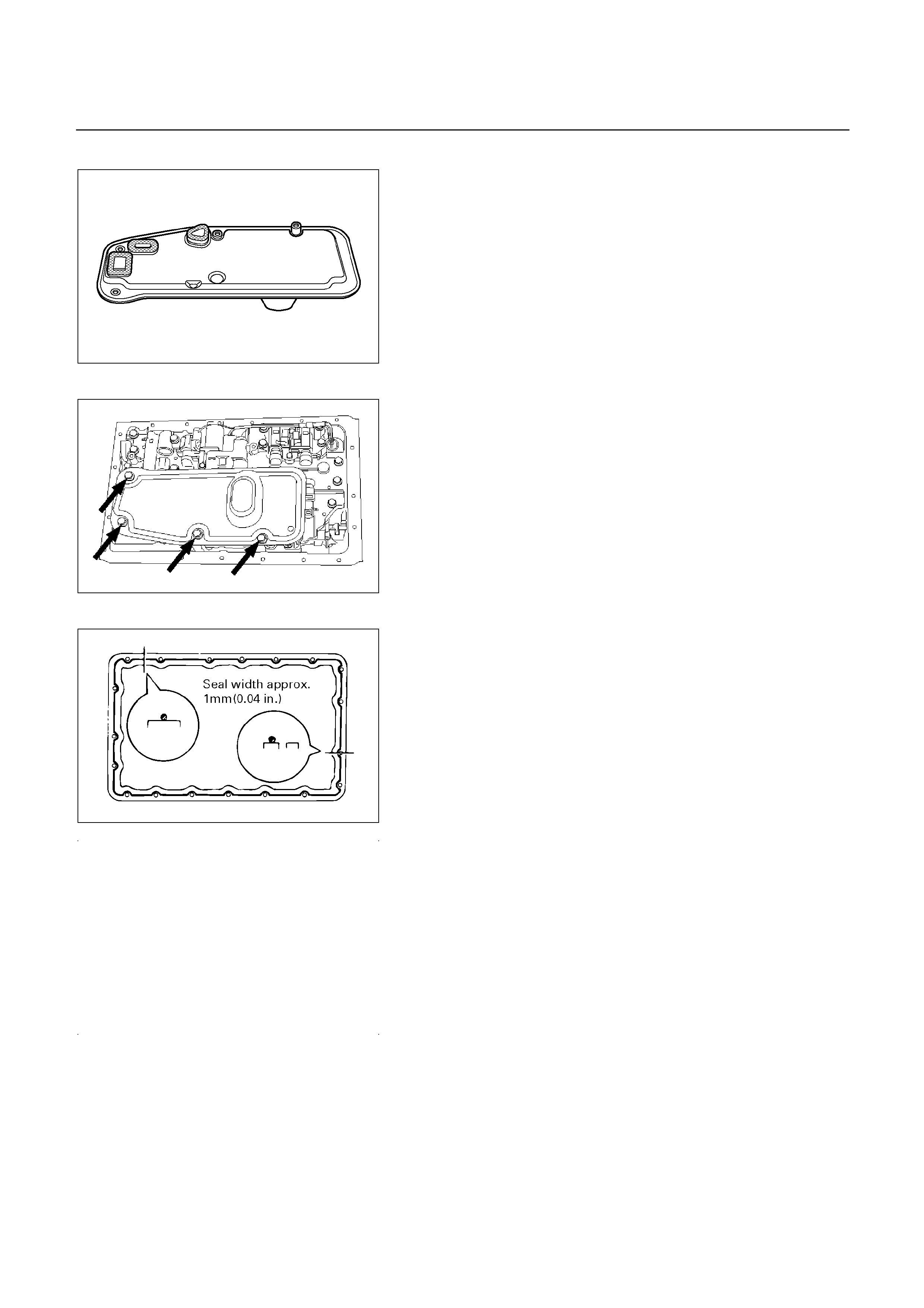
UBS and TFR/S
244RY00002
10. Oil strainer assembly
Install a new oil strainer assembly with gaskets.
244RY00003
Install the oil strainer with the gaskets to the valve body.
Tighten the four bolts.
Torque: 10 N m (1.0 kg m/87 Ib in)
244L100001
11. Oil pan
Install two magnets in oil pan.
Remove any gasket material and be careful not to drop
oil on the contacting surfaces of the transmission case
and oil pan.
Apply liquid gasket (TB1281 or its equivalent) to the oil
pan as shown in the figure.
NOTE:
Install the oil pan as soon as the seal gasket is
applied.

240RY00020
Install and tighten the nineteen bolts.
Torque: 8 N m (0.8 kg m/69 Ib in)
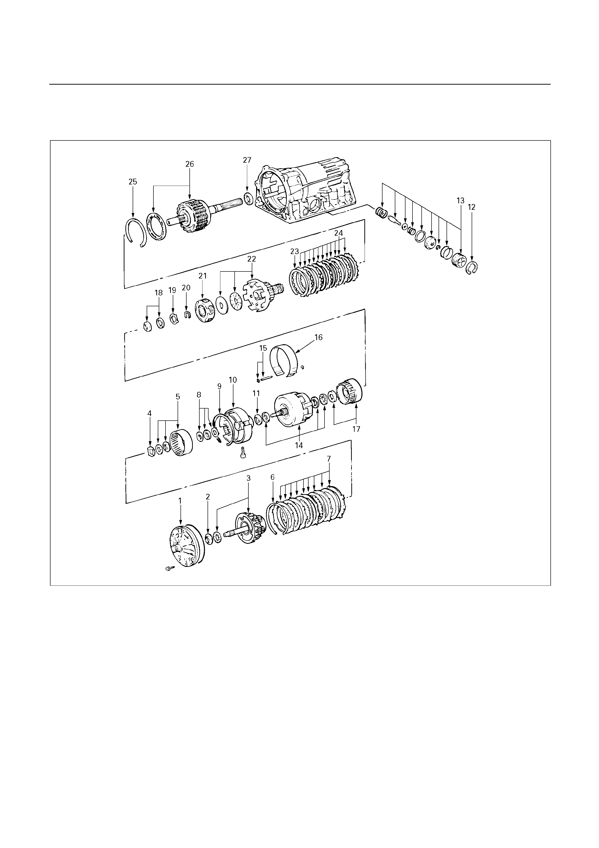
DISASSEMBLY OF MAJOR
COMPONENTS (3)
248L100001

Disassembly steps
1. Oil pump
2. Race
3. OD planetary gear and OD direct clutch
4. Race
5. OD planetary ring gear
6. Snap ring
7. Flange, plate and disc (B-0)
8. Bearing and race
9. Snap ring
10. OD support
11. Race
12. Snap ring
13. Second coast brake piston assembly
14. Direct clutch and forward clutch
15. E-ring and pin
16. Second coast brake band
17. Front planetary ring gear
18. Bearing and race
19. Race
20. Snap ring
21. Front planetary gear
22. Drum and one-way clutch
23. Snap ring
24. Flange, plate and disc (B-2)
25. Snap ring
26. Rear planetary gear, second brake
drum and output shaft
27. Bearing
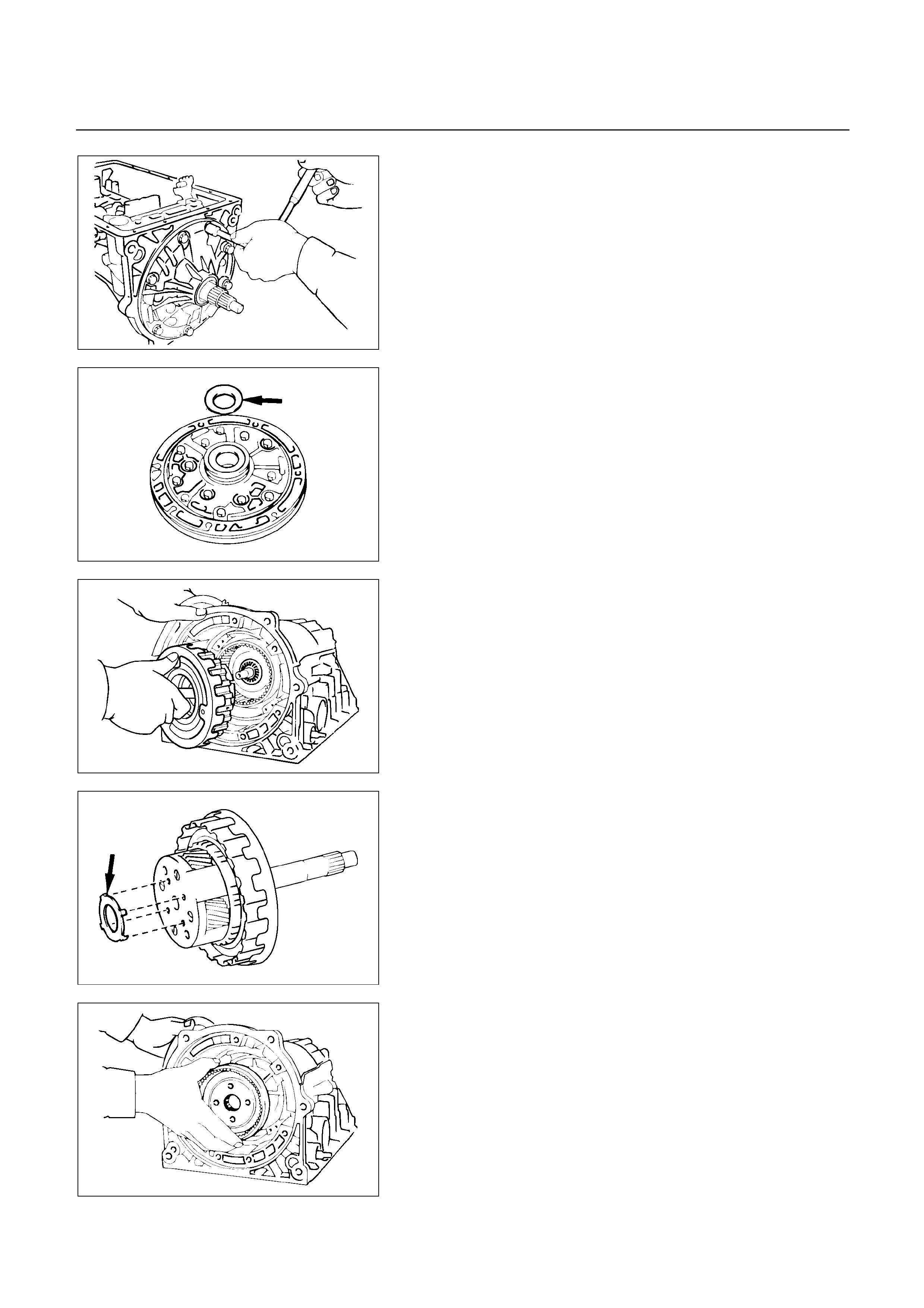
241RY00003
Disassembly steps
1. Oil pump
Remove seven bolts fixing the oil pump to the
transmission case.
Remove the oil pump.
241RY00002
2. Race
Remove race from oil pump.
252L100001
3. OD planetary gear and OD direct clutch
Remove the overdrive planetary gear and overdrive
direct clutch with thrust needle bearing from the
transmission case.
252L100017
4. Race
Remove the race from OD planetary gear.
252RY00002
5. OD planetary ring gear
Remove the overdrive planetary ring gear from the
transmission case.
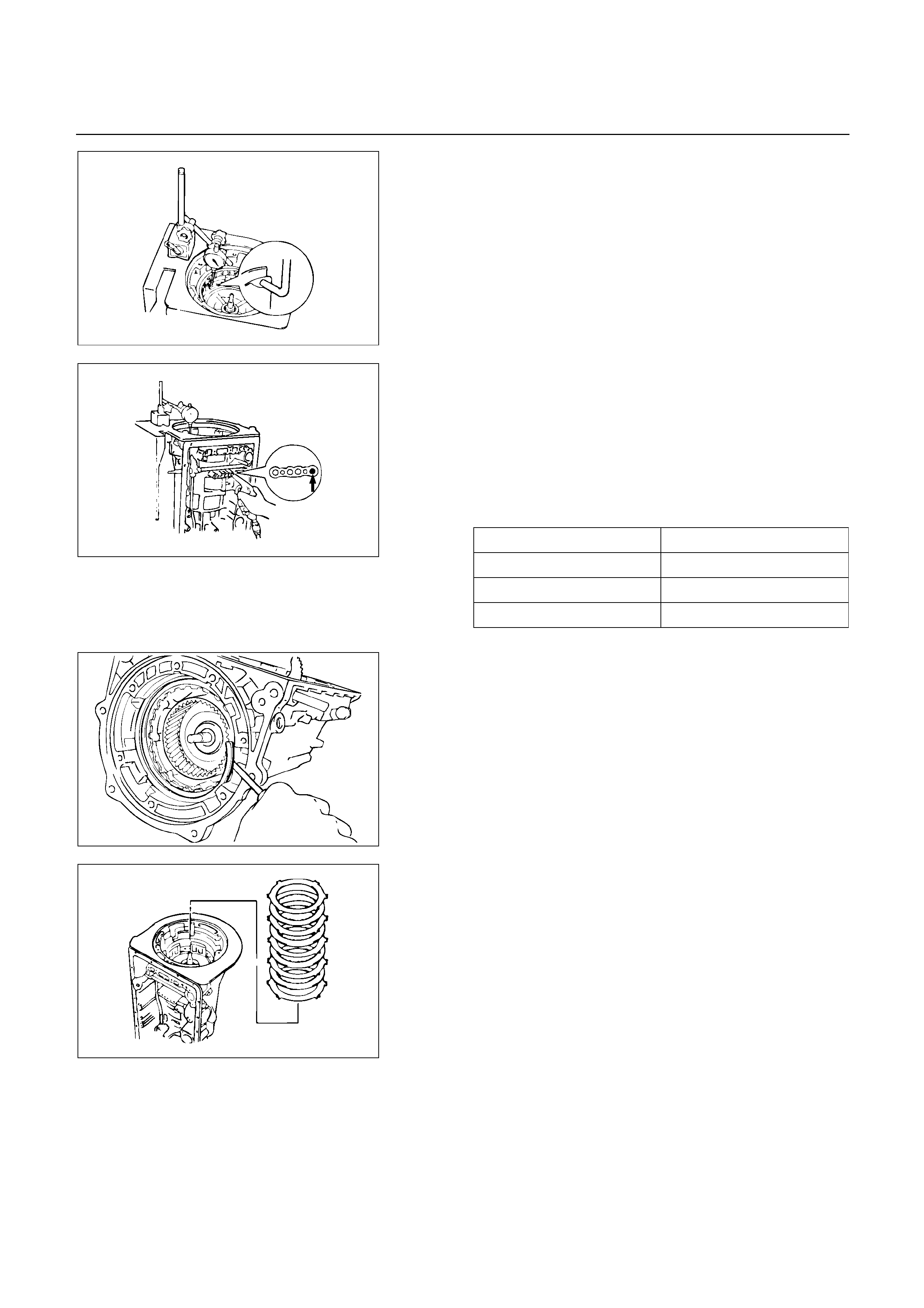
252RY00003
Check piston stroke of overdrive brake
Place a dial indicator onto the overdrive brake piston as
shown in the figure.
Measure the stroke applying and releasing the
compressed air (390 – 780 kPa, 4 – 8 kg/cm2 or 57 –
114 psi) as shown in the figure.
Piston stroke: 1.40 – 1.70 mm (0.0551 – 0.0669 in)
If the values are nonstandard, select another flange.
Available flange sizes
3.3 mm (0.130 in) 3.8 mm (0.150 in)
3.5 mm (0.138 in) 3.9 mm (0.154 in)
3.6 mm (0.142 in) 4.0 mm (0.158 in)
3.7 mm (0.146 in)
244RY00001
246RY00001
6. Snap ring
Remove the snap ring.
246RY00026
7. Flange, plate and disc (B-0)
Remove two flange, three plates and four discs.
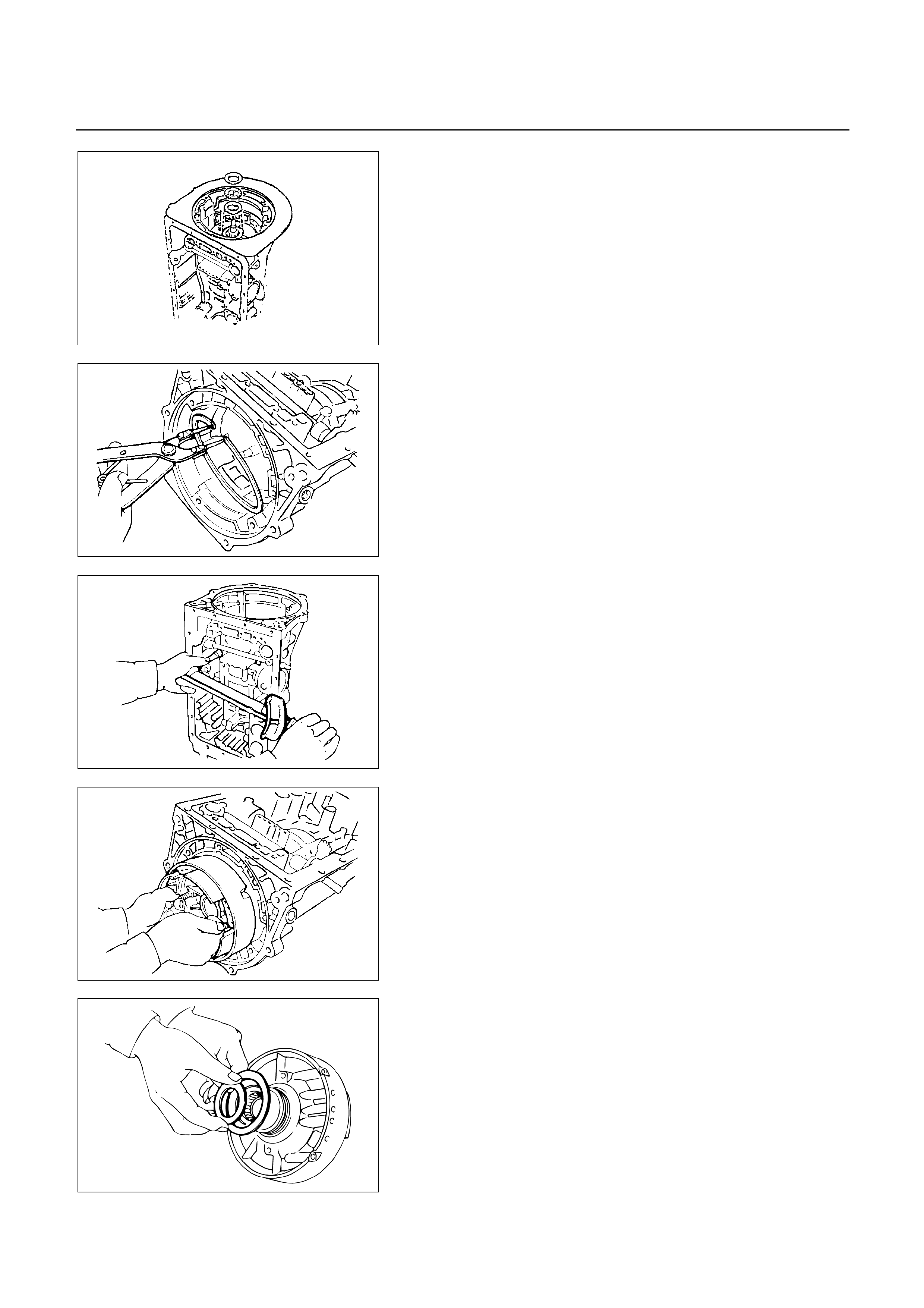
247RY00003
8. Bearing and race
Remove the thrust bearing and two races.
246RY00002
9. Snap ring
Using snap ring pliers, remove the snap ring.
252RY00004
10. OD support
Remove two bolts fixing the overdrive support assembl
y
to the transmission case.
252RY00005
Install two removed bolts to the OD support, and pull
out the OD support assembly.
252RY00006
11. Race
Remove the race from OD support.
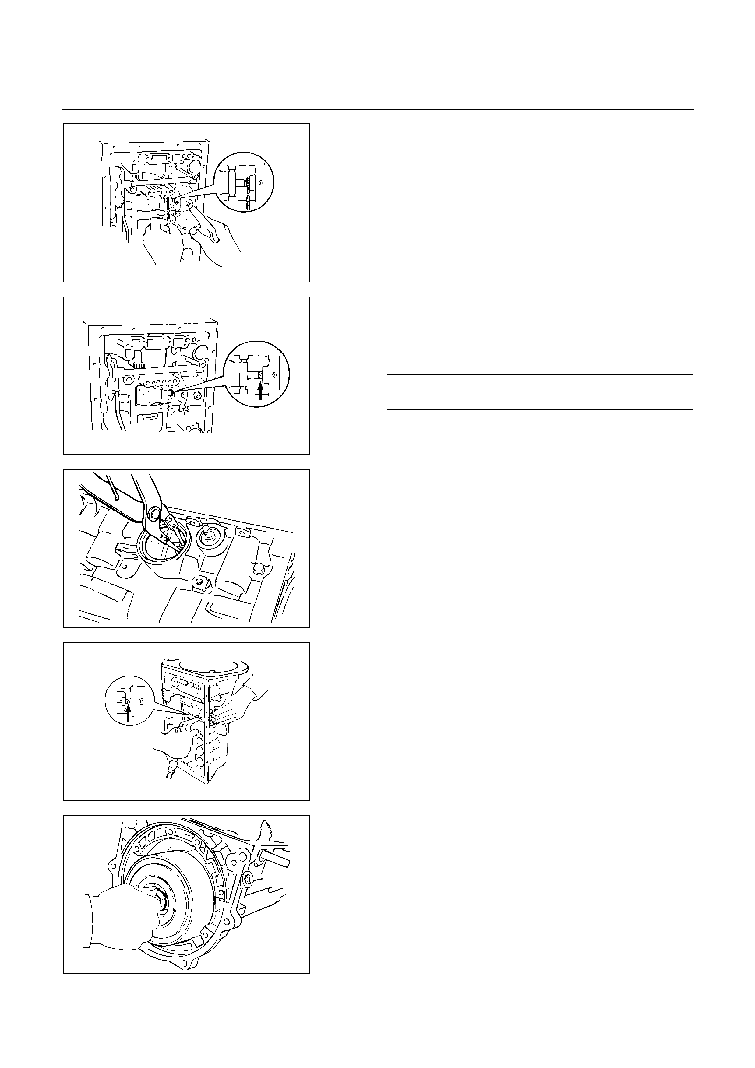
248RY00004
Check piston stroke of second coast brake (B-1)
Place a mark on the second coast brake piston rod as
shown in the figure.
Using feeler gauge, measure the stroke applying the
compressed air (390 – 780 kPa, 4 – 8 kg/cm2 or 57 –
114 psi) as shown in the figure.
Piston stroke: 1.5 – 3.0 mm (0.059 – 0.118 in)
If the values are nonstandard, replace piston rod and
recheck piston stroke.
If piston stroke is nonstandard, replace brake band.
There are two piston rods.
71.4 mm
(
2.811 in
)
Rod length
72.9 mm
(
2.870 in
)
248RY00005
248RY00006
12. Snap ring
Using snap ring pliers, remove the snap ring.
248RY00007
13. Second coast brake piston assembly
Applying compressed air to the oil hole, remove the
second coast brake piston assembly.
248RY00008
14. Direct clutch and forward clutch
Remove the direct clutch and forward clutch from the
transmission case.
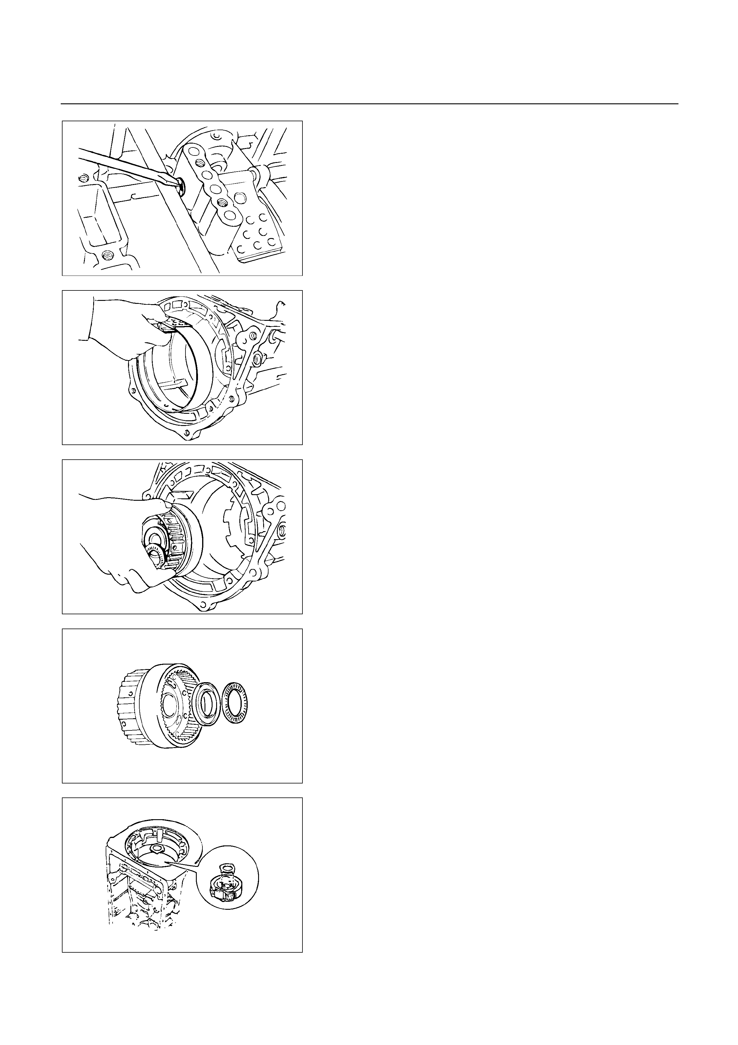
248RY00009
15. E-ring and pin
Remove the E-ring from the pin.
Remove the pin from the brake band.
248RY00010
16. Second coast brake band
Remove the second coast brake band from the
transmission case.
247RY00004
17. Front planetary ring gear
Remove the front planetary ring gear from the
transmission case.
247RY00005
18. Bearing and race
Remove the bearing and race.
247RY00006
19. Race
Remove the race.
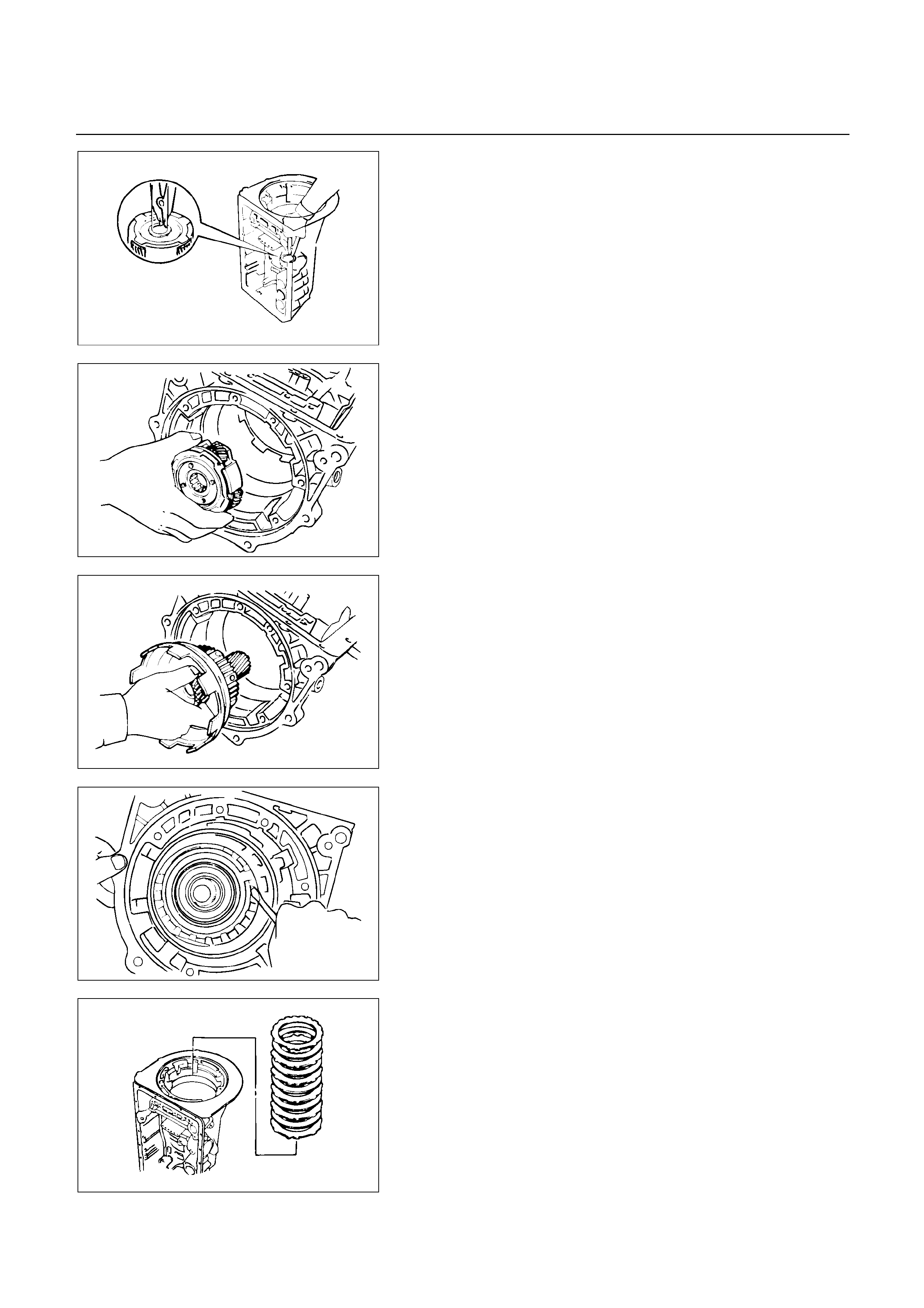
248RY00011
20. Snap ring
Using snap ring pliers, remove the snap ring.
NOTE:
Hold the output shaft to prevent it from falling.
The output shaft falls when the snap ring is
removed.
247RY00007
21. Front planetary gear
Remove the front planetary gear from the transmission
case.
248RY00012
22. Drum and one-way clutch
Remove sun gear input drum and one-way clutch.
248RY00014
23. Snap ring
Using two screwdrivers, remove the snap ring.
248RY00015
24. Flange, plate and disc (B-2)
Remove the flange, five discs and five plates.
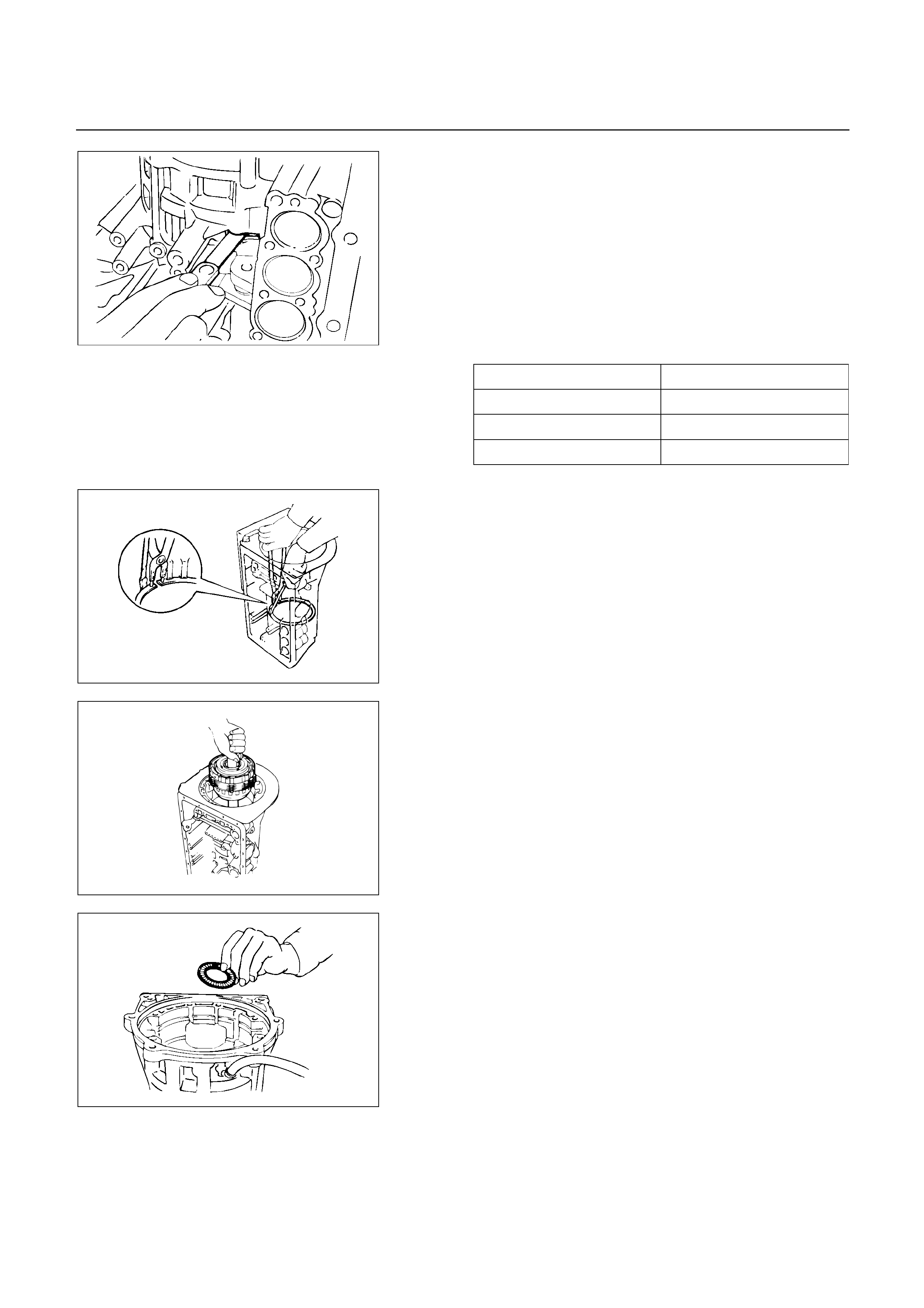
248RY00016
Check pack clearance of first and reverse brake (B-3)
Using a feeler gauge, measure the clearance between
the plate and second brake drum as shown in the
figure.
Clearance: 0.7 – 1.0 mm (0.0276 – 0.0394 in) (UBS)
: 0.6 – 0.9 mm (0.0236 – 0.0354 in) (TFR/S)
If the values are nonstandard, replace the discs.
Available flange sizes
4.0 mm (0.158 in) 4.8 mm (0.189 in)
4.2 mm (0.165 in) 5.0 mm (0.197 in)
4.4 mm (0.173 in) 5.2 mm (0.205 in)
4.6 mm (0.181 in) 5.4 mm (0.213 in)
248RY00017
25. Snap ring
Using snap ring pliers, remove the snap ring.
247R200001
26. Rear planetary gear, second brake drum and output
shaft
Remove the rear planetary gear, second brake drum
and output shaft as an assembly.
248RY00018
27. Bearing
Remove the assembled thrust bearing and race from
the transmission case.
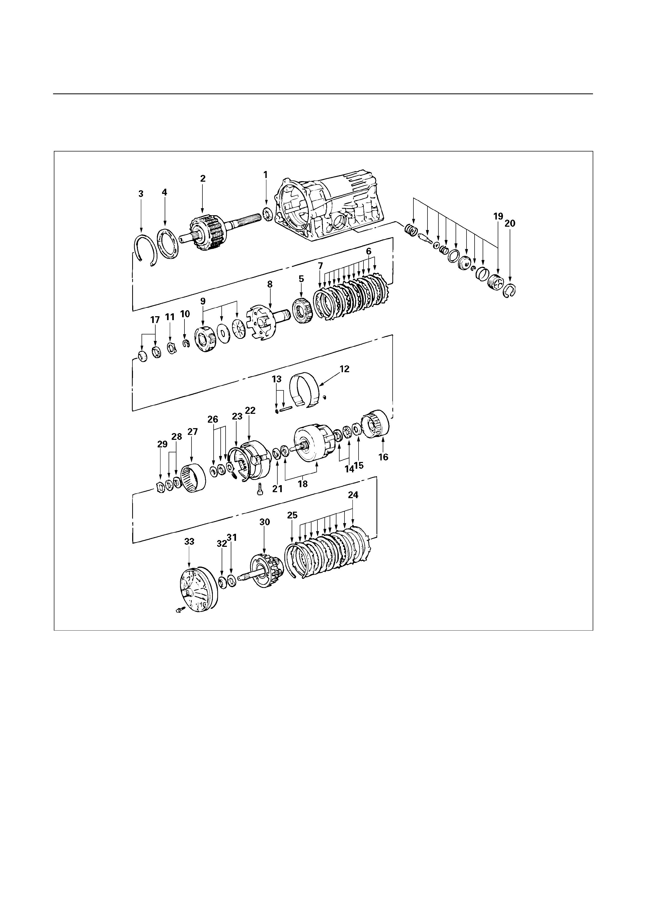
REASSEMBLY OF MAJOR
COMPONENTS (3)
248L100002

Reassembly steps
1. Bearing
2. Rear planetary gear, second brake
drum and output shaft
3. Snap ring
4. Second brake piston sleeve
5. One-way clutch
6. Flange, plate and disc (B-2)
7. Snap ring
8. Drum
9. Front planetary gear and bearing
10. Snap ring
11. Race
12. Second coast brake band
13. E-ring and pin
14. Bearing and race
15. Race
16. Front planetary ring gear
17. Bearing and race
18. Direct clutch and forward clutch
19. Second coast brake piston assembly
20. Snap ring
21. Race
22. OD support
23. Snap ring
24. Flange, plate and disc (B-0)
25. Snap ring
26. Bearing and race
27. OD planetary ring gear
28. Bearing and race
29. Race
30. OD planetary gear and OD direct clutch
31. Bearing
32. Race
33. Oil pump
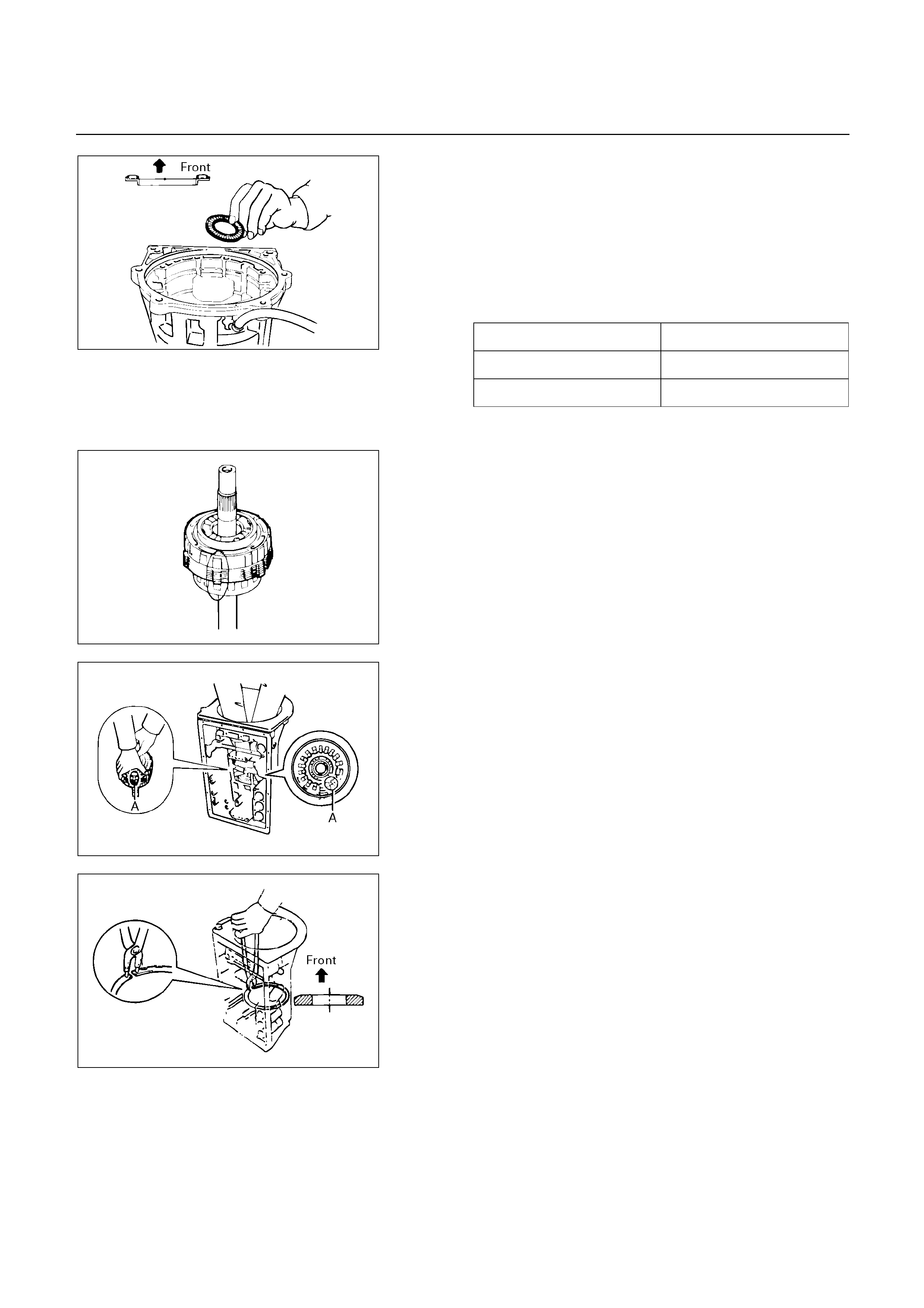
Reassembly steps
1. Bearing
Coast the assembled bearing and race with petroleum
jelly and install it onto the transmission case.
Assembled bearing and race
(Reference)
Bearing and race Diameter
Inside 39.2 mm (1.543 in)
Outside 57.7 mm (2.272 in)
247RY00008
247RY00009
2. Rear planetary gear, second brake drum and output
shaft.
Align the teeth of the second brake drum, flanges, discs
and plates as shown in the figure.
247RY00010
Align the splines of the transmission case and the
assembled rear planetary gear, second brake drum and
output shaft, indicated by A in the figure.
246RY00003
3. Snap ring
Using snap ring pliers, install the snap ring.
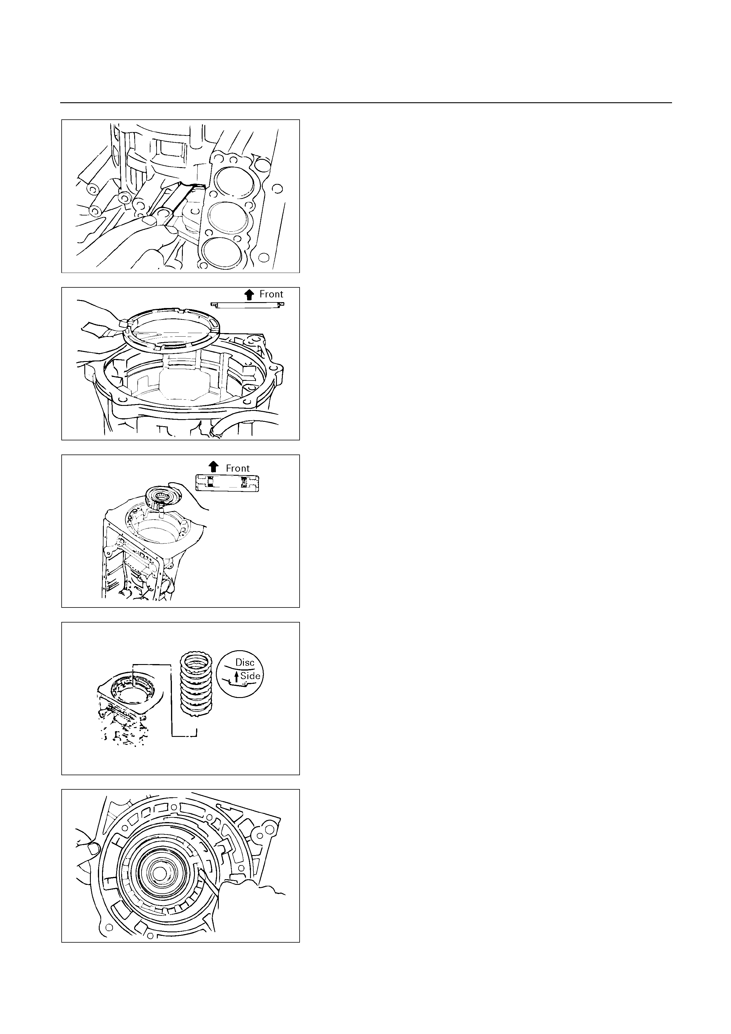
248RY00016
Check pack clearance of first and reverse brake
Using a thickness gauge, measure the clearance
between the plate and second brake drum as shown in
the figure.
Clearance: 0.7 – 1.0 mm (0.0276 – 0.0394 in) (UBS)
0.6 – 0.9 mm (0.0236 – 0.0354 in) (TFR/S)
If the values are nonstandard, check for an improper
installation.
246RY00004
4. Second brake piston sleeve
Install second brake piston sleeve.
247RY00011
5. One-way clutch
Install one-way clutch.
246RY00005
6. Flange, plate and disc (B-2)
Install flange, discs and plates.
Install the 2.5 mm (0.098 in) thick plate with the
rounded edge side of the plate facing the disc.
Alternately install five discs and five plates (Disc first)
Install the flange with the rounded edge of the flange
facing the disc.
248RY00014
7. Snap ring
Install the snap ring.
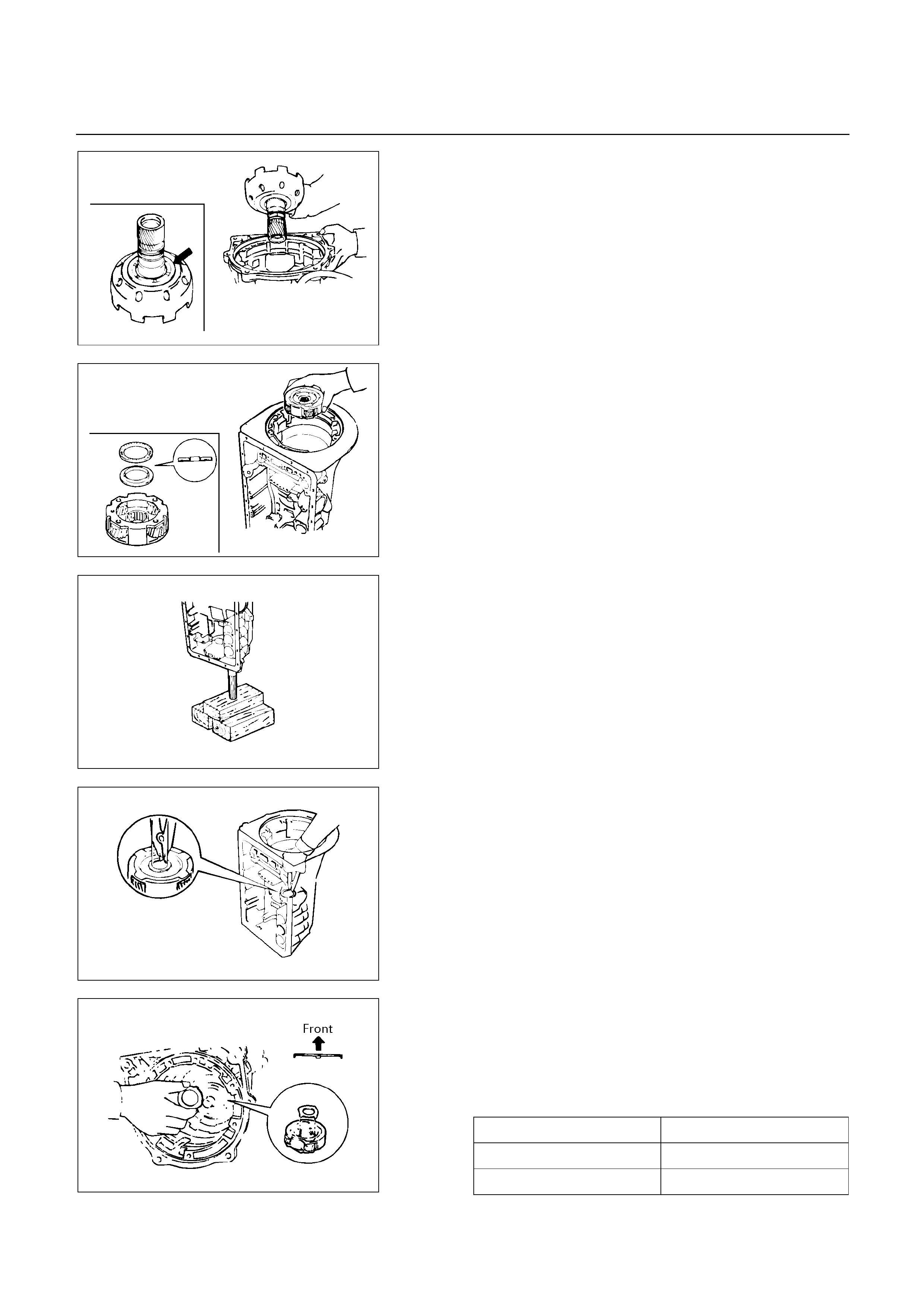
248RY00020
8. Drum
While turning the sun gear input drum clockwise.
Install it into the one-way clutch.
NOTE:
Confirm the thrust washers are installed correctly.
247RY00012
9. Front planetary gear and bearing
Install the front planetary gear to the sun gear.
NOTE:
Confirm the bearing and race is installed correctly.
247RY00013
With wooden blocks under the output shaft, stand the
transmission on the output shaft.
248RY00011
10. Snap ring
Using snap ring pliers, install the snap ring.
11. Race
Coat the bearing race with petroleum jelly and install it
onto the front planetary gear.
Bearing race diameter (Reference)
Bearing race Diameter
Inside 34.3 mm (1.350 in)
Outside 47.8 mm (1.882 in)
247RY00014
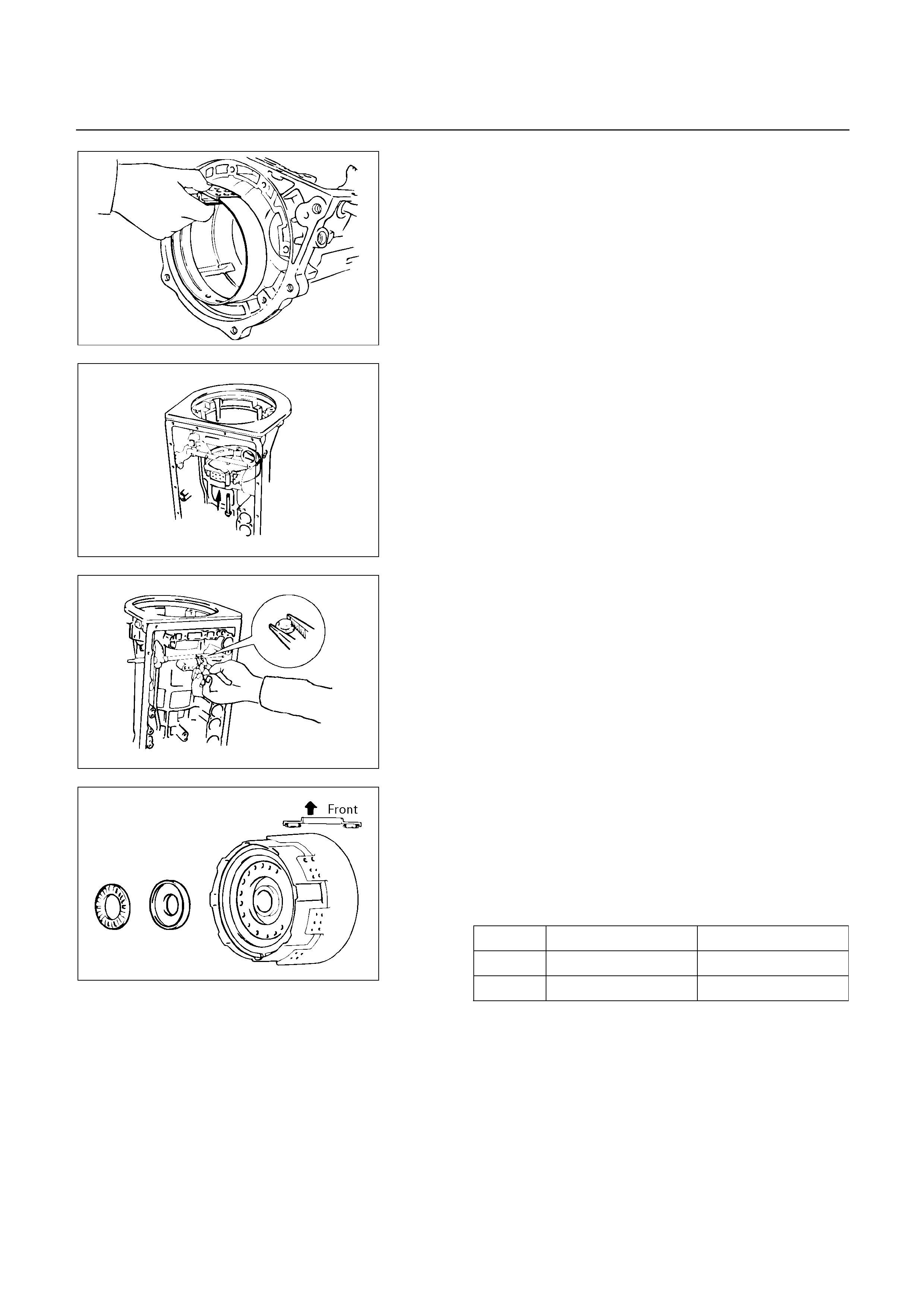
248RY00010
12. Second coast brake band
Insert the second coast brake band to the transmission
case.
248RY00021
13. E-ring and pin
Install the pin through the brake band.
248RY00022
Install the E-ring to the pin.
14. Bearing and race
Coat the bearing and race with petroleum jelly and
install them onto the forward clutch.
Bearing and race diameter (Reference)
Inside Outside
Bearing 26.0 mm (1.024 in) 46.7 mm (1.839 in)
Race 26.0 mm (1.024 in) 48.9 mm (1.925 in)
248RY00023
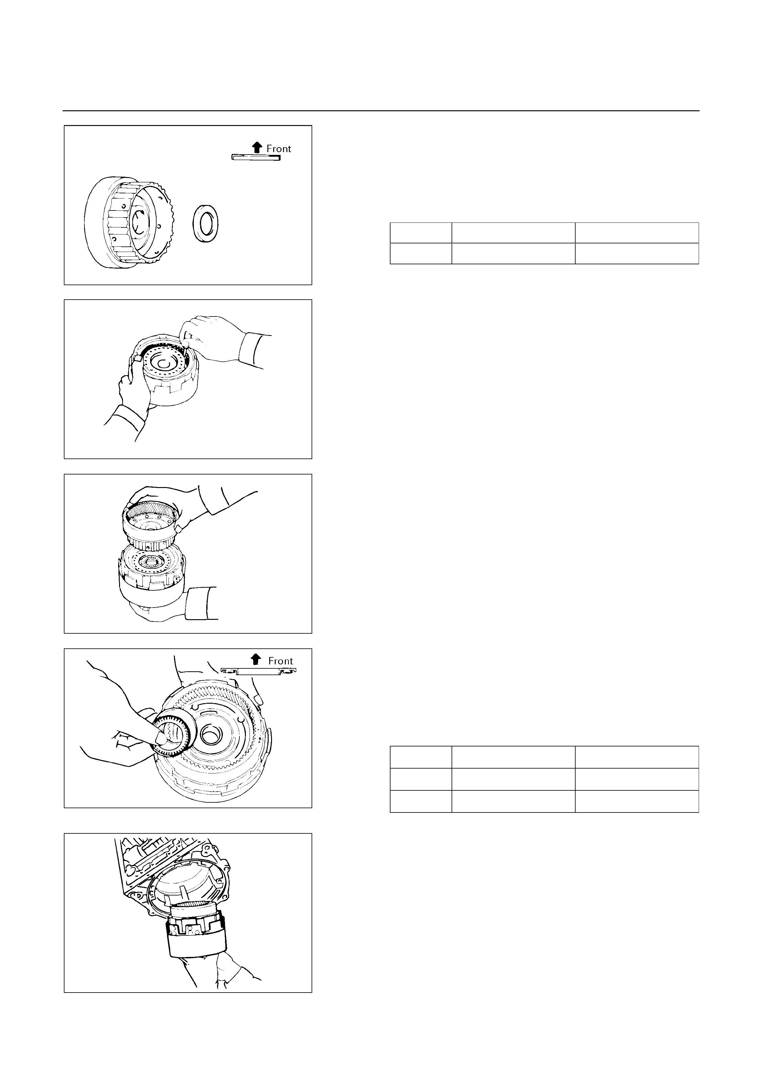
15. Race
Coat the race with petroleum jelly and install it onto the
front planetary ring gear.
Race diameter (Reference)
Inside Outside
Race 26.8 mm (1.055 in) 47.0 mm (1.850 in)
247RY00015
247RY00016
Align the flukes of the discs in the forward clutch.
247RY00017
16. Front planetary ring gear
Align the spline of the front planetary gear with the
flukes of the discs and install the front planetary gear to
the forward clutch.
17. Bearing and race
Coat the bearing and race with petroleum jelly and
install them onto the ring gear.
Bearing and race diameter (Reference)
Inside Outside
Bearing 32.6 mm (1.283 in) 47.7 mm (1.878 in)
Race 30.6 mm (1.205 in) 53.6 mm (2.110 in)
247RY00019
247RY00018
18. Direct clutch and forward clutch
Install the assembled direct clutch, forward clutch and
front planetary ring gear into the transmission case.

248RY00024
Using vernier calipers, measure the distance between
the sun gear input drum and direct clutch drum as
shown in the figure.
Height: 9.8 – 11.8 mm (0.386 – 0.465 in)
If the values are nonstandard, check for an improper
installation.
Coat the assembled bearing and race with petroleum
jelly and install it onto the forward clutch.
Assembled bearing and race diameter
(Reference)
Inside Outside
Bearing
and race 33.7 mm (1.327 in) 47.8 mm (1.882 in)
248RY00025
248RY00026
19. Second coast brake piston assembly
Coat the oil seal ring with ATF and install it to the
second coast brake piston.
Install the washer, spring and piston to the piston rod.
Install the E-ring.
: Second coast brake piston
: Oil seal
: Piston rod
248RY00027
20. Snap ring
Coat two new oil seals with ATF and install them to the
piston cover.
Install the spring, second coast brake piston assembl
y
and piston cover to the transmission case.
Using snap ring pliers, install the snap ring.
248RY00005
Check piston stroke of second coast brake
Place a mark on the second coast brake piston rod as
shown in the figure.
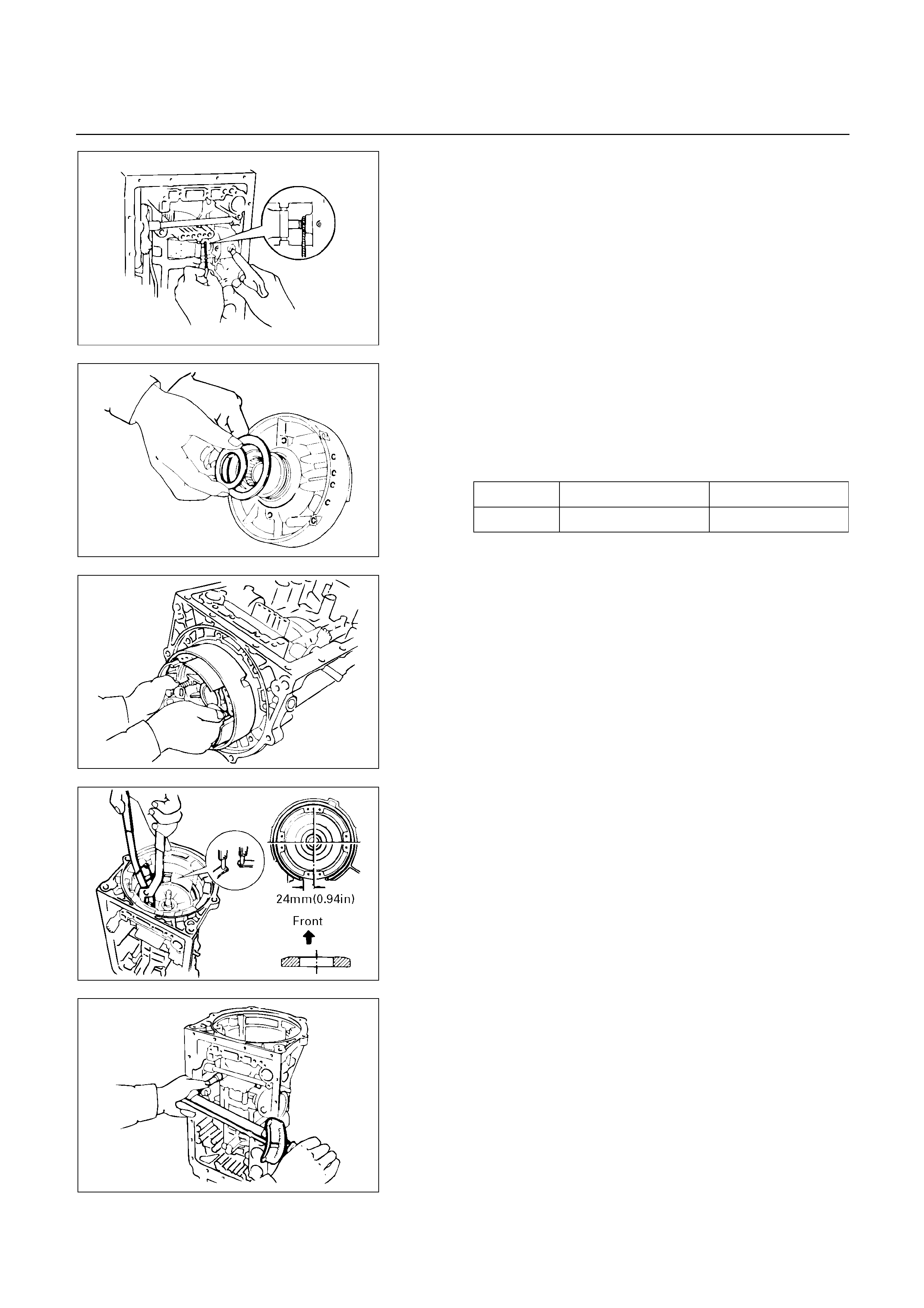
248RY00004
Using wire gauge, measure the stroke by applying the
compressed air (390 – 780 kPa, 4 – 8 kg/cm2 or 57 –
114 psi) as shown in the figure.
Piston stroke: 1.5 – 3.0 mm (0.059 – 0.118 in)
If the values are nonstandard, check for an improper
installation.
21. Race
Coat the race with petroleum jelly and install it onto the
overdrive support assembly.
Race diameter (Reference)
Inside Outside
Race 36.8 mm (1.449 in) 50.9 mm (2.004 in)
252RY00007
252RY00005
22. OD support
Aim the bolt and oil holes of the overdrive support
toward the valve hole side, and align them with the bolt
hole of the transmission case and insert.
252RY00008
23. Snap ring
Using snap ring pliers, install the snap ring as shown in
the figure.
252RY00004
Install and tighten the two bolts.
Torque: 25 N m (2.6 kg m/19 Ib ft)
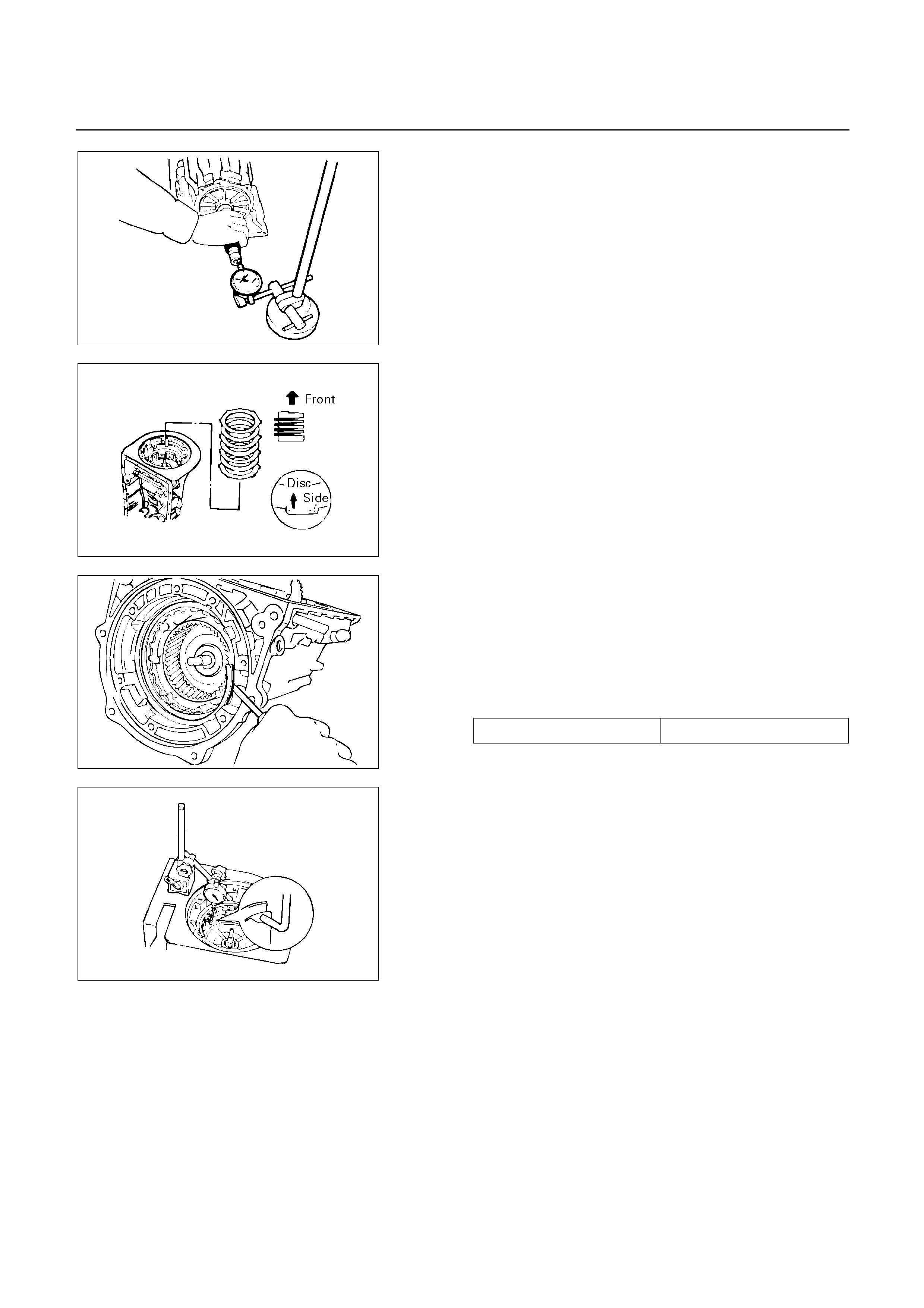
247RY00020
Check end of output shaft
Using a dial indicator, measure the end play of the
output shaft by hand.
End play: 0.27 – 0.86 mm (0.0106 – 0.0339 in)
252RY00009
24. Flange, plate and disc (B-0)
Install the (flat ring) 4.0 mm (0.157 in) thick flange with
the rounded edge side of the flange facing the disc.
Alternately install four discs and three plates. (Disc first)
25. Snap ring
Install the (stepped ring) flange with the flat side of the
flange facing the disc.
Install the snap ring.
Snap ring (Reference)
Inside diameter 167.9 mm (6.61 in)
246RY00001
252RY00003
Check piston stroke of overdrive brake
Place a dial indicator onto the overdrive brake piston as
shown in the figure.
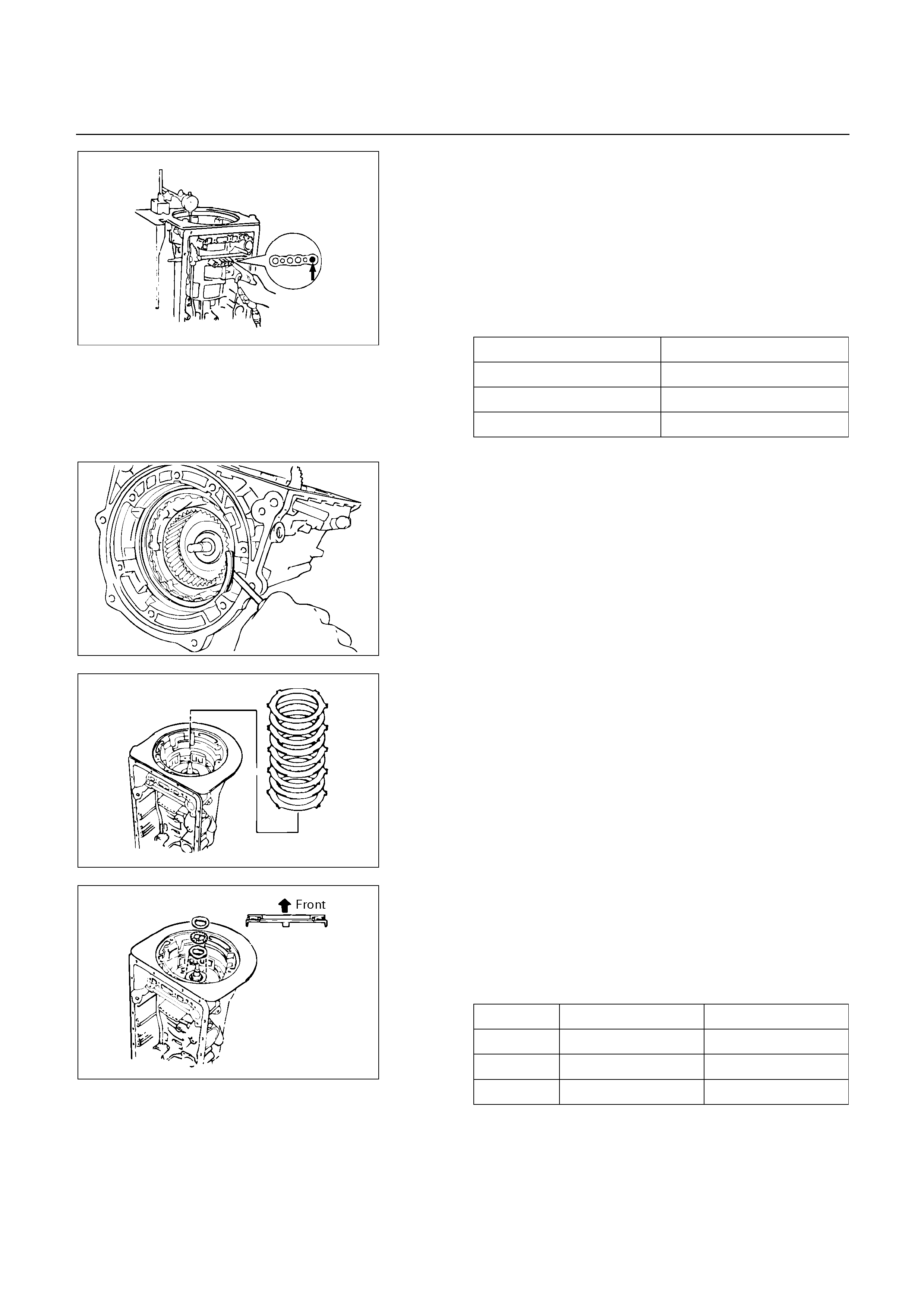
Measure the stroke by applying and releasing the
compressed air (390 – 780 kPa, 4 – 8 kg/cm2 or 57 –
114 psi) as shown in the figure.
Piston stroke: 1.40 – 1.70 mm (0.0551 – 0.0669 in)
If the values are nonstandard, check for an improper
installation.
Available flange size
3.3 mm (0.130 in) 3.8 mm (0.150 in)
3.5 mm (0.138 in) 3.9 mm (0.154 in)
3.6 mm (0.142 in) 4.0 mm (0.158 in)
3.7 mm (0.146 in)
244RY00001
246RY00001
Remove the snap ring.
246RY00026
Remove two flanges, three plates and four discs.
26. Bearing and race
Coat the bearing and races with petroleum jelly and
install them onto the overdrive support.
Bearing and races diameter (Reference)
Inside Outside
Bearing 36.5 mm (1.437 in) 48.4 mm (1.906 in)
Race (Front) 37.2 mm (1.465 in) 58.8 mm (2.315 in)
Race (Rear) 33.7 mm (1.327 in) 50.1 mm (1.972 in)
252RY00010
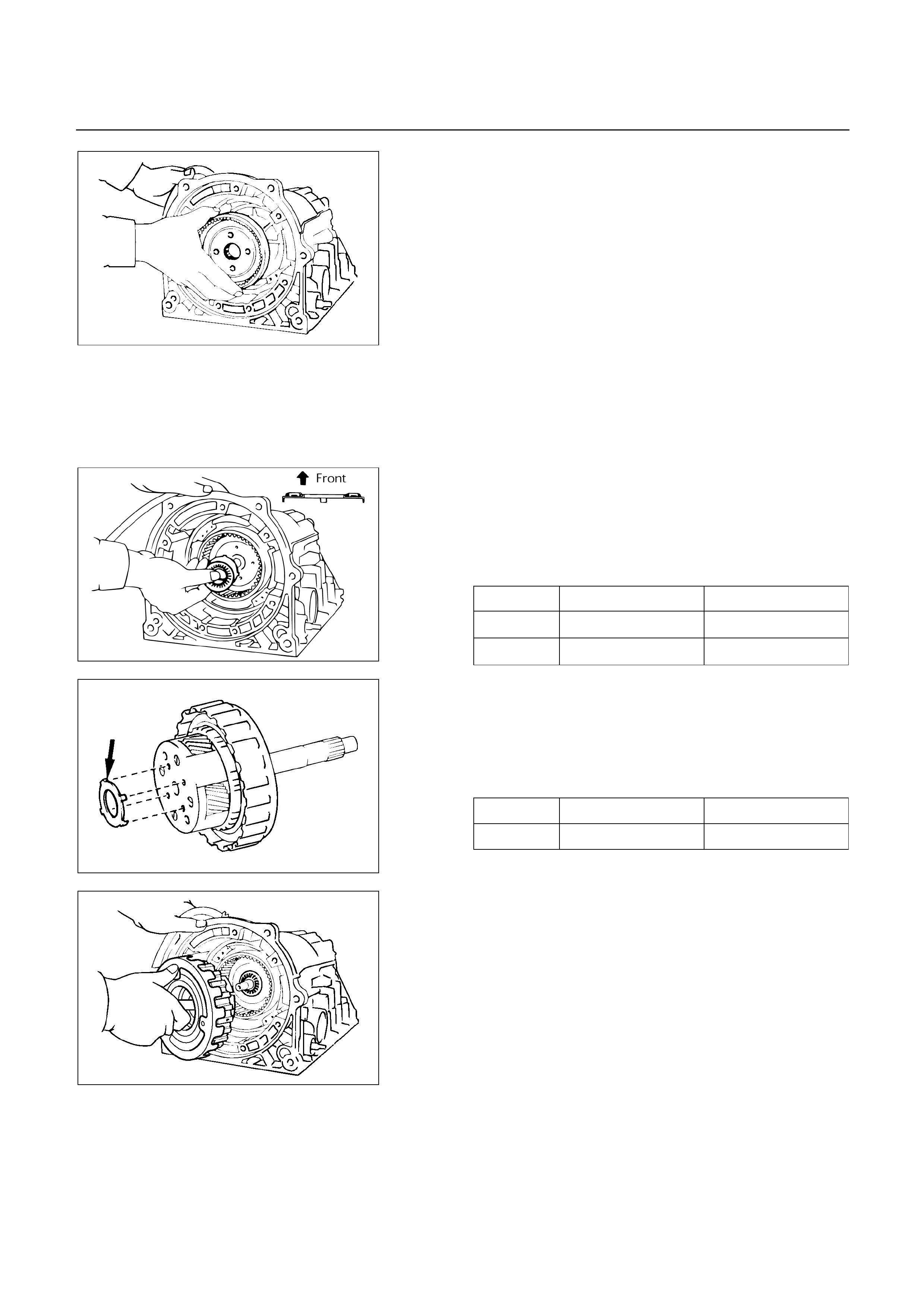
252RY00002
27. OD planetary ring gear
Install the overdrive planetary ring gear.
28. Bearing and race
Coat the bearing and race with petroleum jelly and
install them onto the planetary ring gear.
Bearing and race diameter (Reference)
Inside Outside
Bearing 26.0 mm (1.024 in) 46.8 mm (1.843 in)
Race 24.2 mm (0.953 in) 47.8 mm (1.882 in)
252RY00011
29. Race
Coat the race with petroleum jelly and install it onto the
planetary gear.
Race diameter (Reference)
Inside Outside
Race 27.3 mm (1.075 in) 41.8 mm (1.646 in)
252RY00001
252L100001
30. OD planetary gear and OD direct clutch
Install the overdrive planetary gear and direct clutch.
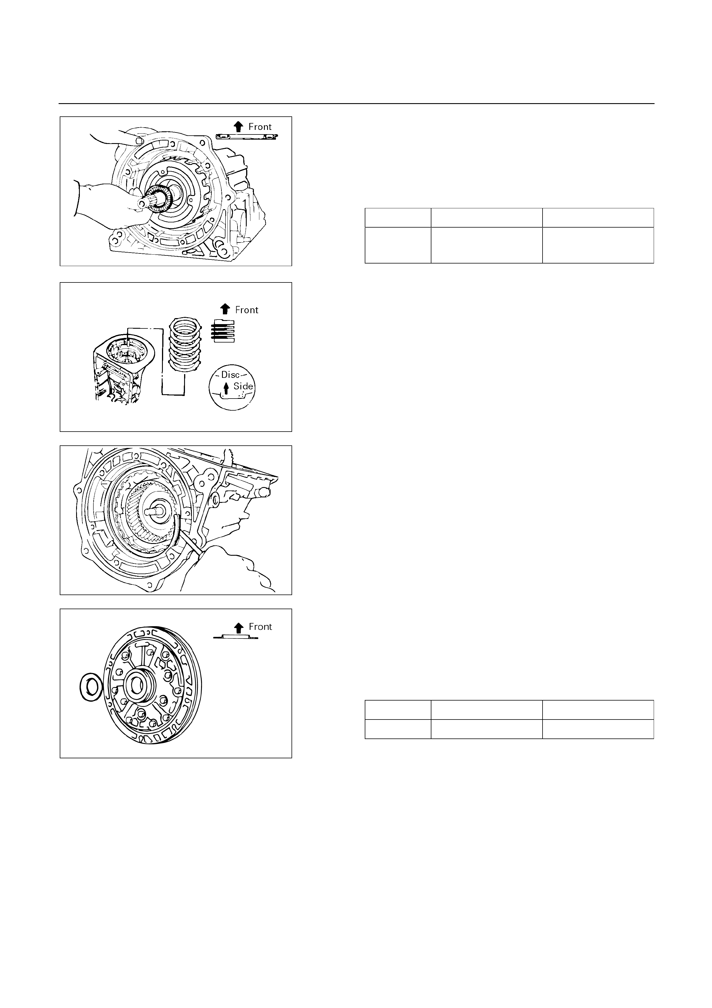
31. Bearing
Coat the assembled bearing and race with petroleum
jelly and install it onto the direct clutch.
Bearing and race diameter (Reference)
Inside Outside
Bearing
and race 28.9 mm (1.138 in) 50.2 mm (1.976 in)
252L100018
252RY00009
Install the (flat ring) 4.0 mm (0.157 in) thick flange with
the rounded edge side of the flange facing the disc.
Alternately install four discs and three plates. (Disc first)
246RY00001
Install the (stepped ring) flange with the flat side of the
flange facing the disc.
Install the snap ring.
32. Race
Coat the race with petroleum jelly and install it onto the
oil pump.
Race diameter (Reference)
Inside Outside
Race 28.1 mm (1.106 in) 47.3 mm (1.862 in)
252RY00014

241RY00003
33. Oil pump
Coat the O-ring with ATF and install it around the pump
body.
Place the oil pump through the input shaft, and align the
bolt holes of the pump body with the transmission case.
Hold the input shaft, and lightly press the oil pump bod
y
to slide the oil seal rings on the stator shaft through the
direct clutch drum.
CAUTION:
Do not push on the oil pump strongly or the oil seal
ring will stick to the direct clutch drum.
Install the seven bolts.
Torque: 22 N m (2.2 kg m/16 Ib ft)
Check input shaft rotation
Make sure the input shaft rotates smoothly.

DISASSEMBLY, INSPECTION AND
REASSEMBLY OF MINOR COMPONENTS
NOTE:
The instructions here are organized so that you work on
only one component group at a time.
This will help avoid confusion from similar-looking parts of
different subassemblies being on your workbench at the
same time.
The component groups are inspected and repaired from
the converter housing side.
As much as possible, complete the inspection, repair and
reassembly before proceeding to the next component
group. If a component group cannot be reassembled
because parts are being ordered, be sure to keep all parts
of that group in separate container while proceeding with
disassembly, inspection, repair and reassembly of other
component groups.
Recommended ATF type BESCO ATF .
GENERAL CLEANING NOTES:
1. All disassembled parts should be washed clean and an
y
fluid passages and holes blown through with compressed
air.
2. When using compressed air to dry parts, always aim
away from yourself to prevent accidentally spraying
automatic transmission fluid in your face.
3. The recommended automatic transmission fluid should be
used for cleaning.
PARTS ARRANGEMENT:
1. After cleaning, the parts should be arranged in prope
r
order to allow performing inspection, repairs, and
reassembly with efficiency.
2. When disassembling a valve body, be sure to keep each
valve together with the corresponding spring.
3. New brakes and clutches that are to be used fo
r
replacement must be soaked in transmission fluid for at
least thirty minutes before assembly.
GENERAL ASSEMBLY:
1. All oil seal rings, clutch discs, clutch plates, rotating parts,
and sliding surfaces should be coated with transmission
fluid prior to reassembly.
2. All gaskets and rubber O-ring should be replaced.
3. Make sure that the ends of a snap ring are not aligned
with one of the cutouts and are installed in the groove
correctly.
4. If a worn bushing is to be replaced, the subassembl
y
containing that bushing must be replaced.
5. Check thrust bearings and races for wear or damage.
Replace if necessary.
6. Use petroleum jelly or vaseline to keep parts in place.

OIL PUMP
DISASSEMBLY
241R200003
Disassembly steps
1. Oil seal ring
2. O-ring
3. Stator shaft
4. Oil pump drive gear
5. Oil pump driven gear
6. Oil pump body
241RY00005
Disassembly steps
1. Oil seal ring
Use torque converter as work stand.
Remove 2 oil seal rings from stator shaft.
2. O-ring
Remove O-ring.

241RY00006
3. Stator shaft
4. Oil pump drive gear
5. Oil pump driven gear
6. Oil pump body
Remove 13 bolts, and then remove the stator shaft from
oil pump body.
Then remove drive and driven gear.
INSPECTION AND REPAIR
Make necessary correction or parts replacement i
f
wear, damage or any abnormal conditions are found
through inspection.
241RY00007
Check oil pump body bushing
Using a dial indicator, measure the inside diameter o
f
the oil pump body bushing.
Maximum inside diameter: 38.19 mm (1.5035 in)
If the inside diameter is greater than the maximum,
replace the oil pump body.
241RY00008
Check stator shaft bushing
Using a dial indicator, measure the inside diameter o
f
the stator shaft bushing.
Maximum inside diameter:
Front side: 21.58 mm (0.8496 in)
Rear side: 27.08 mm (1.0661 in)
If the inside diameter is greater than the maximum,
replace the stator shaft.
241RY00009
Check tip clearance of both gears
Measure between the gear teeth and the cresent-
shaped part of the pump body.
Standard tip clearance: 0.11 – 0.14 mm
(0.0043 – 0.0055 in)
Maximum tip clearance: 0.3 mm (0.012 in)
If the tip clearance is greater than the maximum,
replace the drive gear, driven gear or pump body.
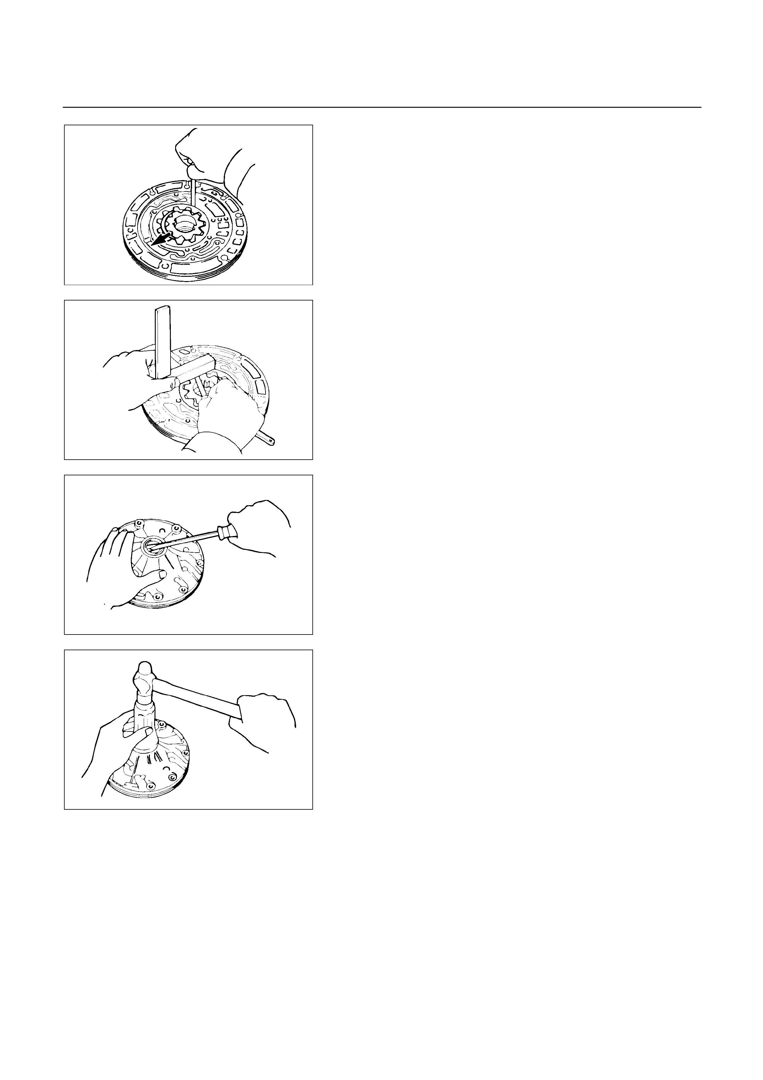
241RY00010
Check body clearance of driven gear
Push the driven gear to one side of the body.
Use a feeler gauge, measure the clearance.
Standard body clearance: 0.07 – 0.15 mm
(0.0028 – 0.0059 in)
Maximum body clearance: 0.3 mm (0.012 in)
If the body clearance is greater than the maximum,
replace the drive gear, driven gear or pump body.
241RY00011
Check side clearance of both gears
Using a steel straightedge and a feeler gauge, measure
the side clearance of both gears.
Standard side clearance: 0.02 – 0.05 mm
(0.0008 – 0.0020 in)
Maximum side clearance: 0.1 mm (0.004 in)
If the side clearance is greater than the maximum,
replace the drive gear, driven gear or pump body.
241RY00012
Check oil seal
Check for wear, damage or cracks.
If necessary, replace oil seal.
Pry off the oil seal with a screwdriver.
241RY00013
Using special tool, install a new oil seal.
The oil seal end should be flush with the outer edge o
f
the pump body.
Oil seal installer : 5-8840-2256-0 (J-9617)
Coat the oil seal lip with multi purpose grease.
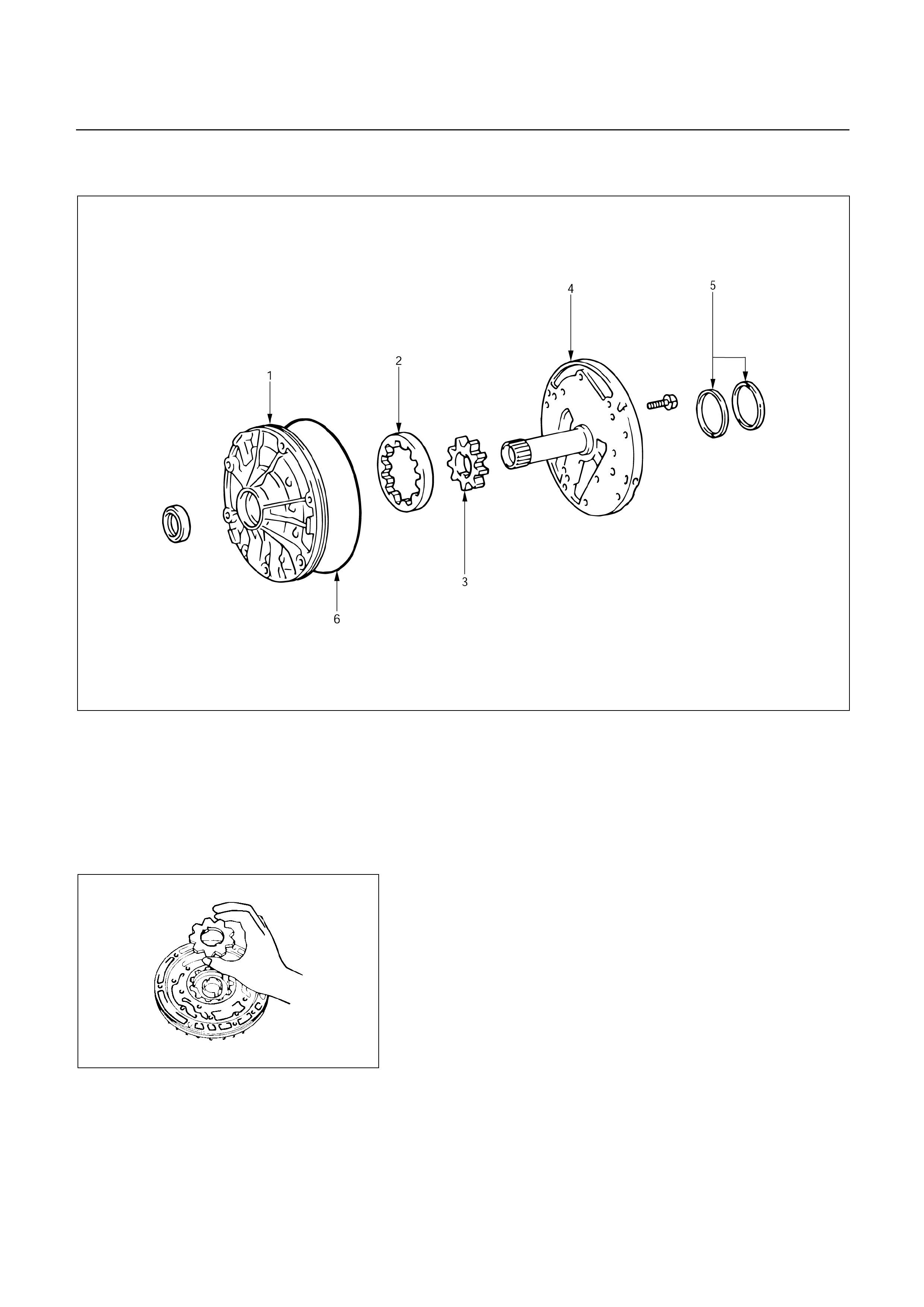
REASSEMBLY
241R200004
Reassembly steps
1. Oil pump body
2. Oil pump driven gear
3. Oil pump drive gear
4. Stator shaft
5. Oil seal ring
6. O-ring
241RY00014
Reassembly steps
1. Oil pump body
2. Oil pump driven gear
3. Oil pump drive gear
Place the oil pump body on the torque converter.
Coat the driven gear and drive gear with ATF.
Install the driven gear and drive gear.
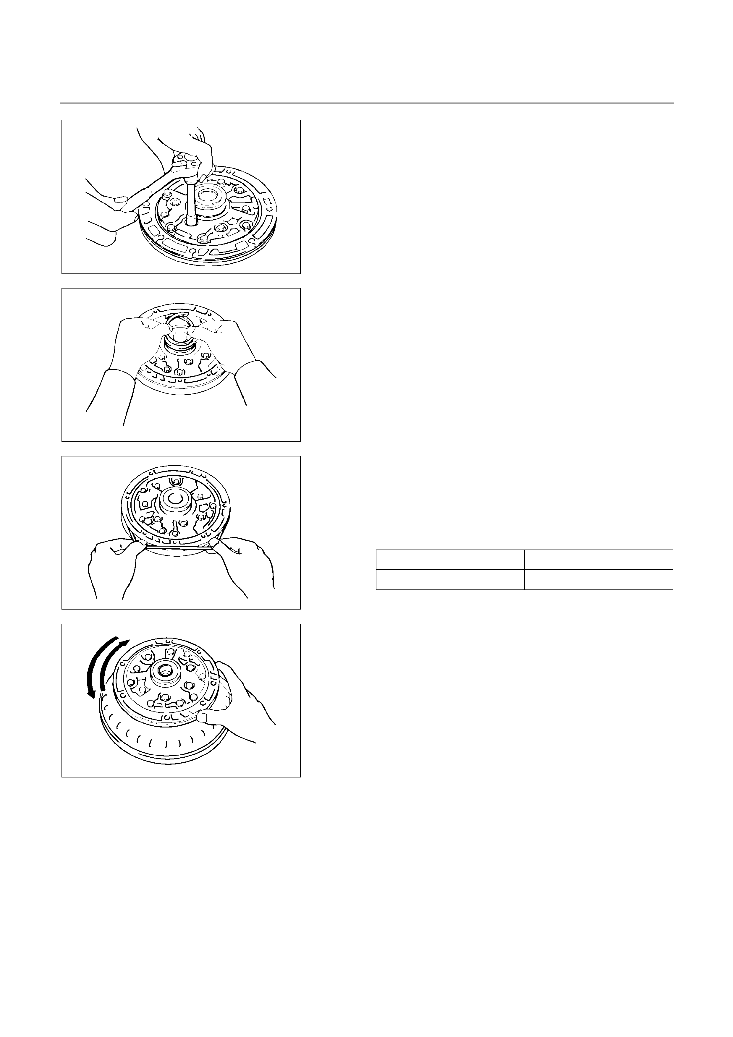
241RY00006
4. Stator shaft
Align the stator shaft with the bolt holes.
Tighten the thirteen bolts.
Torque: 11 N m (1.1 kg m/95 Ib in)
241RY00015
5. Oil seal ring
Coat the oil seal rings with ATF.
Contract the oil seal rings as shown, and install them
onto the stator shaft.
NOTE:
Do not spread the ring ends too much.
6. O-ring
Coat a new O-ring with ATF and install it to the oil pump
body.
O-ring size (Reference)
Inside diameter 204.9 mm (8.067 in)
Thickness 3.5 mm (0.138 in)
241RY00016
241RY00017
Check oil pump drive gear rotation
Make sure the drive gear rotates smoothly when
installed to the torque converter.
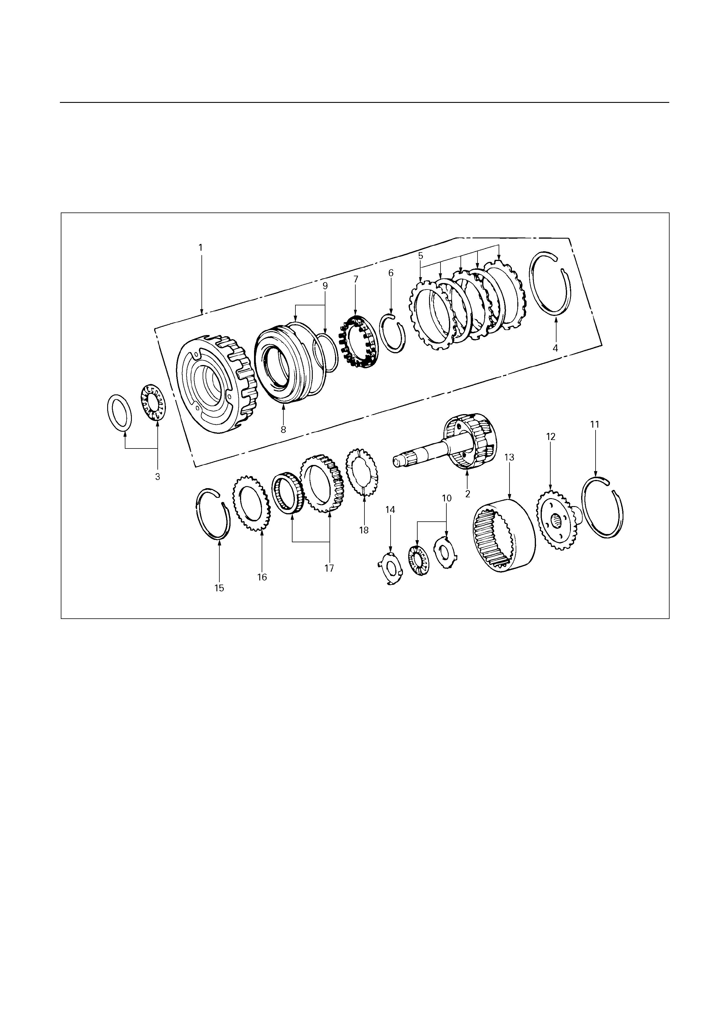
OD PLANETARY GEAR AND OD
DIRECT CLUTCH ASSEMBLY (C-0)
DISASSEMBLY
252R200007
Disassembly steps
1. OD direct clutch assembly
2. OD planetary gear assembly
3. Thrust bearing
4. Snap ring
5. Flange, disk and plate
6. Snap ring
7. Piston return spring
8. OD direct clutch piston with O-ring
9. O-ring
10. Thrust bearing
11. Snap ring
12. Ring gear flange
13. OD planetary ring gear
14. Race
15. Snap ring
16. Retaining plate
17. OD one-way clutch
18. Thrust washer
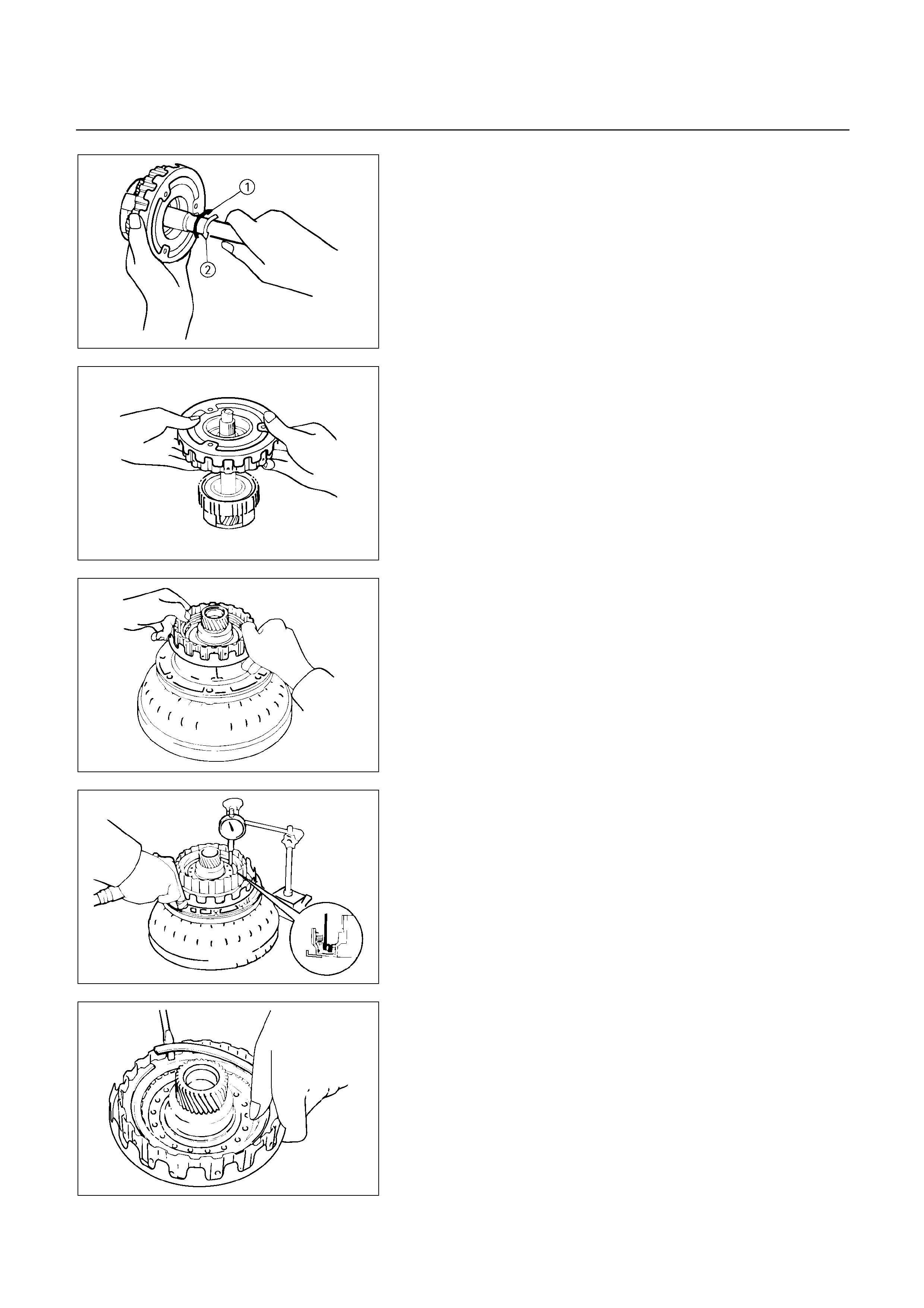
252L100003
Disassembly steps
Check operation of one-way clutch
Hold the OD direct clutch drum and turn the input shaft.
The input shaft should turn freely clockwise and should
lock counterclockwise.
1 : Free
2 : Lock
252L100004
1. OD direct clutch assembly
2. OD planetary gear assembly
Remove OD direct clutch assembly from OD planetar
y
gear assembly.
3. Thrust bearing
Then remove thrust bearing with the race from OD
direct clutch drum.
252L100005
Check piston stroke of OD direct clutch (C-0)
Place the oil pump onto the torque converter, and then
place the OD direct clutch assembly onto the oil pump.
252L100016
Use a dial indicator, measure the OD direct clutch
piston stroke applying and releasing the compressed ai
r
(390 – 780 kPa, 4 – 8 kg/cm2 or 57 – 114 psi) as
shown.
Piston stroke: 1.85 – 2.15 mm (0.0728 – 0.0846 in)
252L100006
4. Snap ring
Remove snap ring from clutch drum.
5. Flange, disc and plate
Remove flange, two discs and two plates.
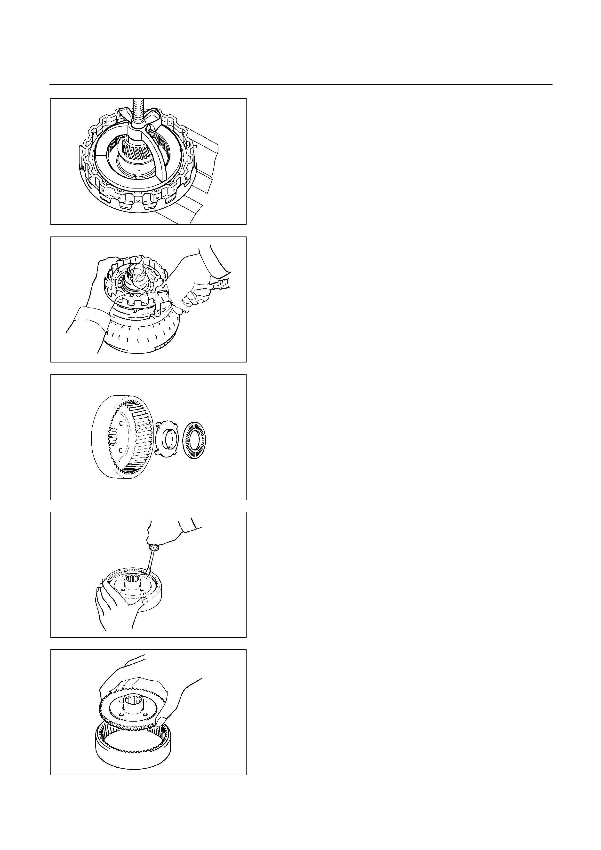
252L100007
6. Snap ring
Place special tool on the spring retainer and compress
the return spring.
Using snap ring pliers, remove the snap ring.
Spring compressor : 5-8840-0195-0 (J-23327-1)
7. Piston return spring
Remove piston return spring
252L100008
8. OD direct clutch piston with O-ring.
Place the oil pump onto the torque converter and then
place the OD direct clutch onto the oil pump.
Holding the OD direct clutch piston by hand, appl
y
compressed air to the oil pump to remove the OD direct
clutch piston.
Remove the OD direct clutch piston.
9. O-ring
Remove two O-rings from piston.
252RY00021
10. Thrust bearing
Remove bearing and race from OD planetary ring gear.
252RY00022
11. Snap ring
Remove snap ring.
252RY00023
12. Ring gear flange
13. OD planetary ring gear
Remove ring gear flange from OD planetary ring gear.
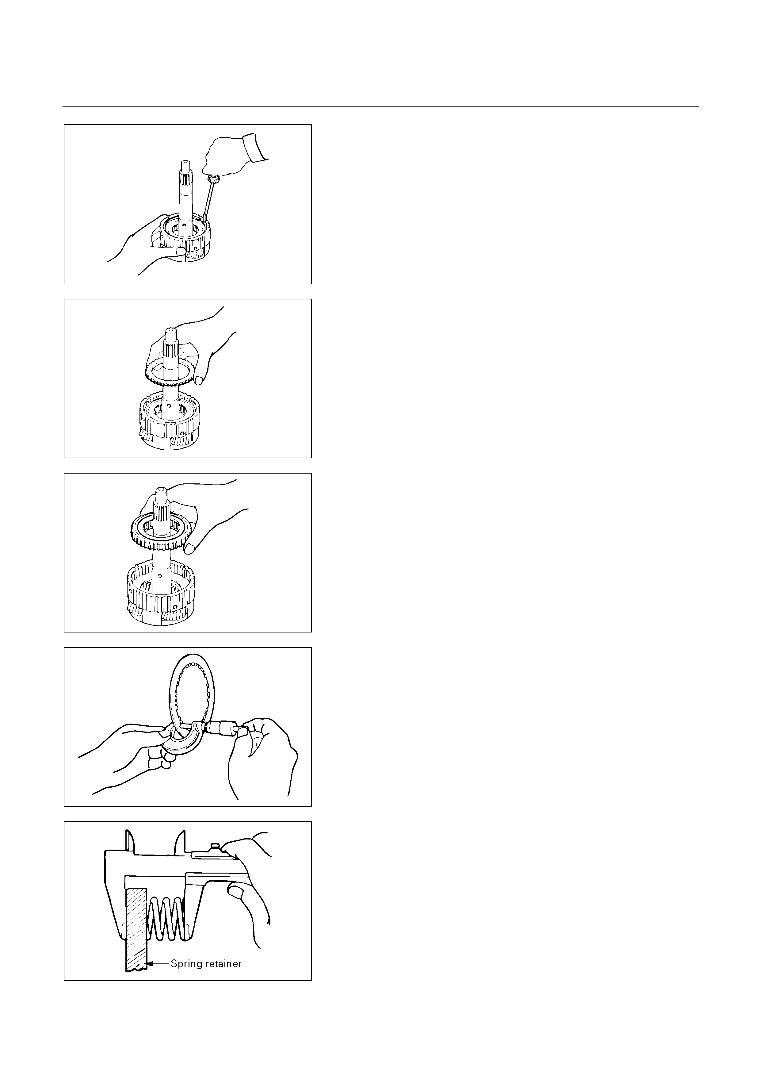
252RY00024
14. Race
15. Snap ring
Remove snap ring, using screwdriver.
252RY00025
16. Retaining plate
Remove retaining plate from OD planetary gear.
252RY00026
17. OD one-way clutch
Remove OD one-way clutch with outer race.
18. Thrust washer
252RY00027
INSPECTION AND REPAIR
Check discs
Using a micrometer, measure the thickness of the
discs.
Minimum thickness: 1.84 mm (0.0724 in)
If the thickness is less than the minimum, replace the
disc.
252RY00028
Check piston return spring
Using calipers, measure the free length of the return
spring.
Standard length: 15.8 mm (0.622 in)
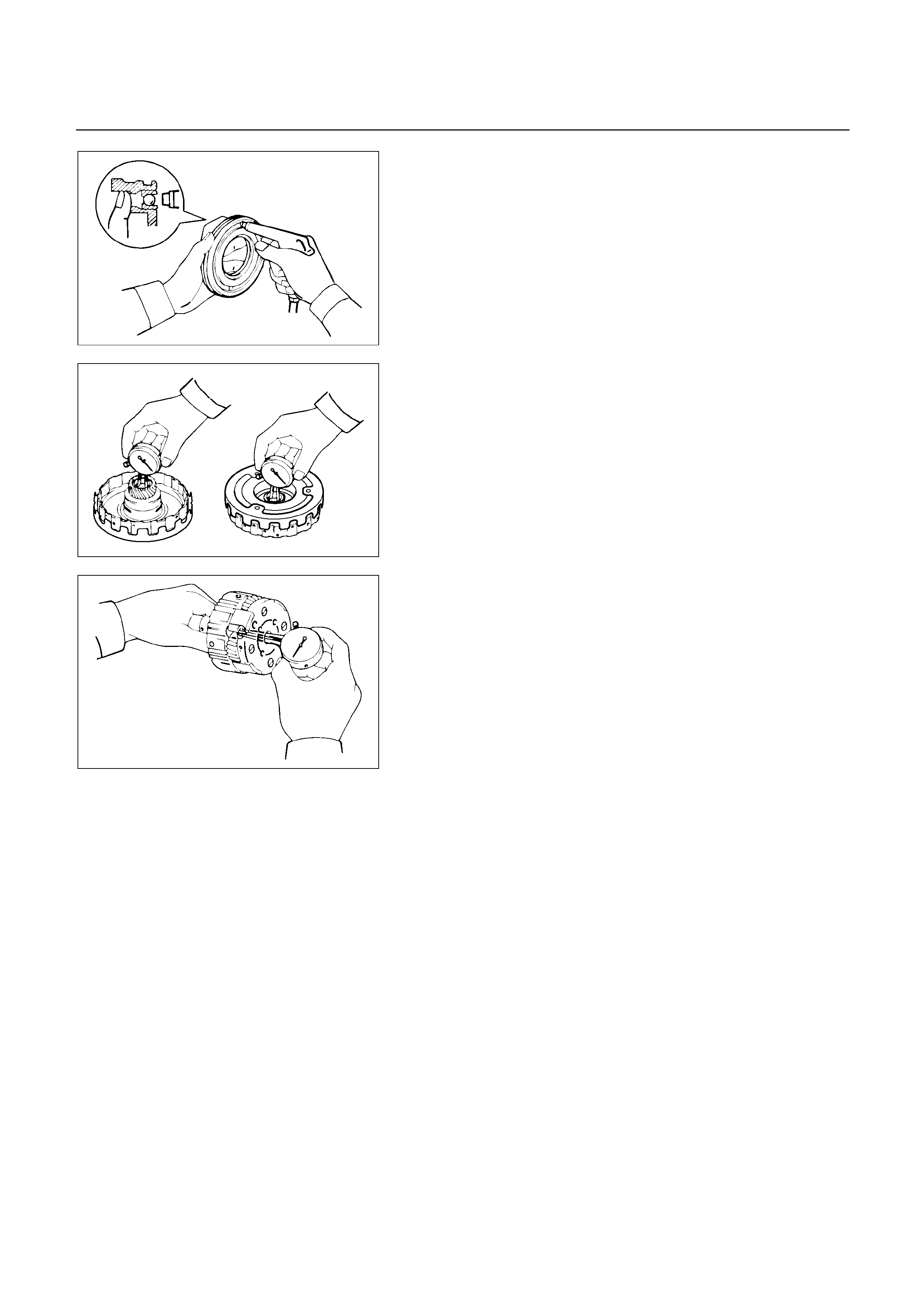
252RY00029
Check OD direct clutch piston
Check that the check ball is free by shaking the piston.
Check that the valve does not leak by applying low-
pressure compressed air.
252L100009
Check OD direct clutch drum bushings
Using a dial indicator, measure the inside diameter o
f
the OD direct clutch drum bushings.
Maximum inside diameter: 27.11 mm (1.0673 in)
If the inside diameter is greater than the maximum,
replace the OD direct clutch drum.
252RY00031
Check OD planetary gear bushing
Using a dial indicator, measure the inside diameter o
f
replace the OD planetary gear bushing.
Maximum inside diameter: 11.27 mm (0.4437 in)
If the inside diameter is greater than the maximum,
replace the OD planetary gear.
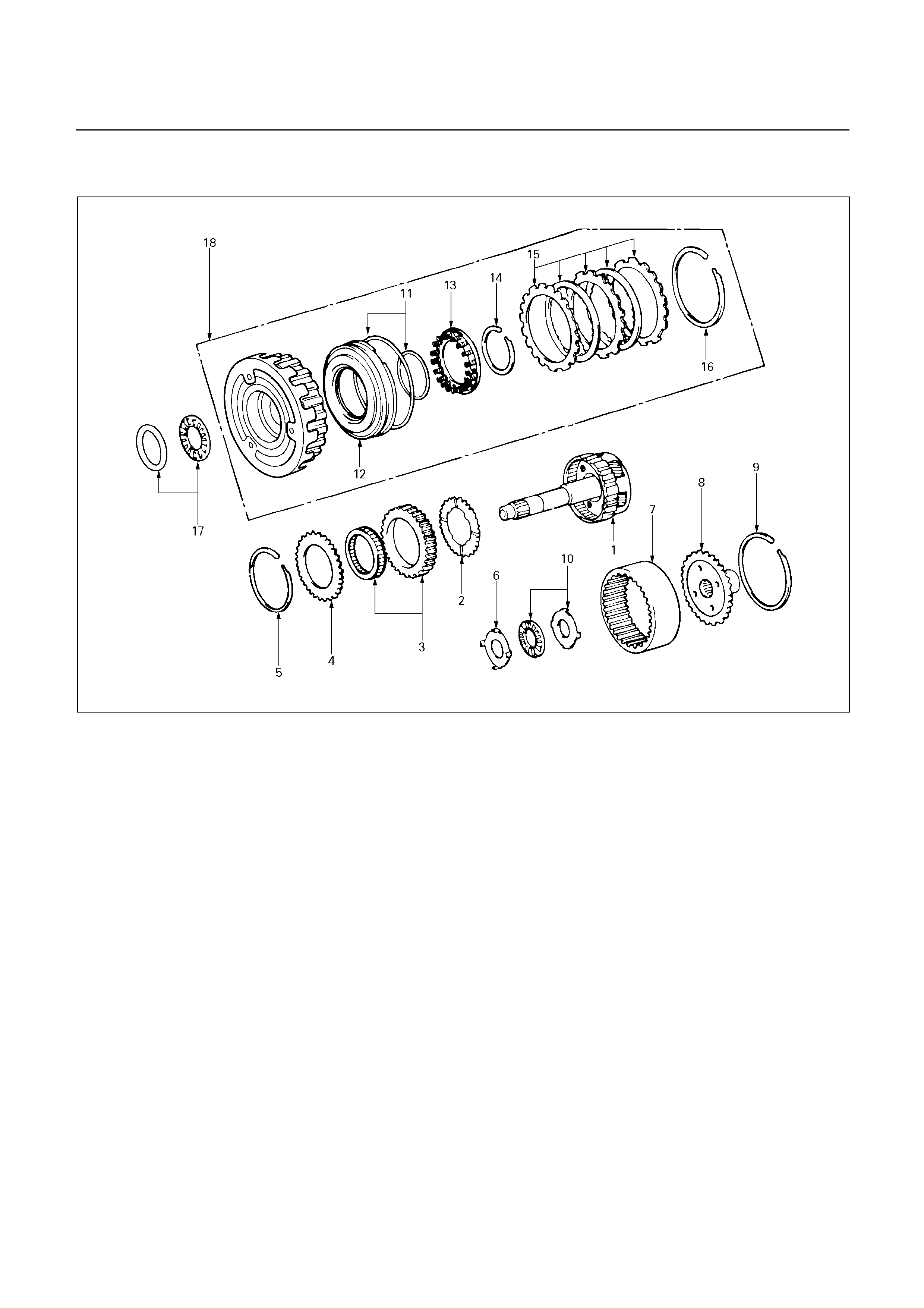
REASSEMBLY
252R200008
Reassembly steps
1. OD planetary gear assembly
2. Thrust washer
3. OD one-way clutch
4. Retaining plate
5. Snap ring
6. Race
7. OD planetary ring gear
8. Ring gear flange
9. Snap ring
10. Thrust bearing
11. O-ring
12. OD direct clutch piston with O-ring
13. Piston return spring
14. Snap ring
15. Flange, disc and plate
16. Snap ring
17. Thrust bearing
18. OD direct clutch assembly
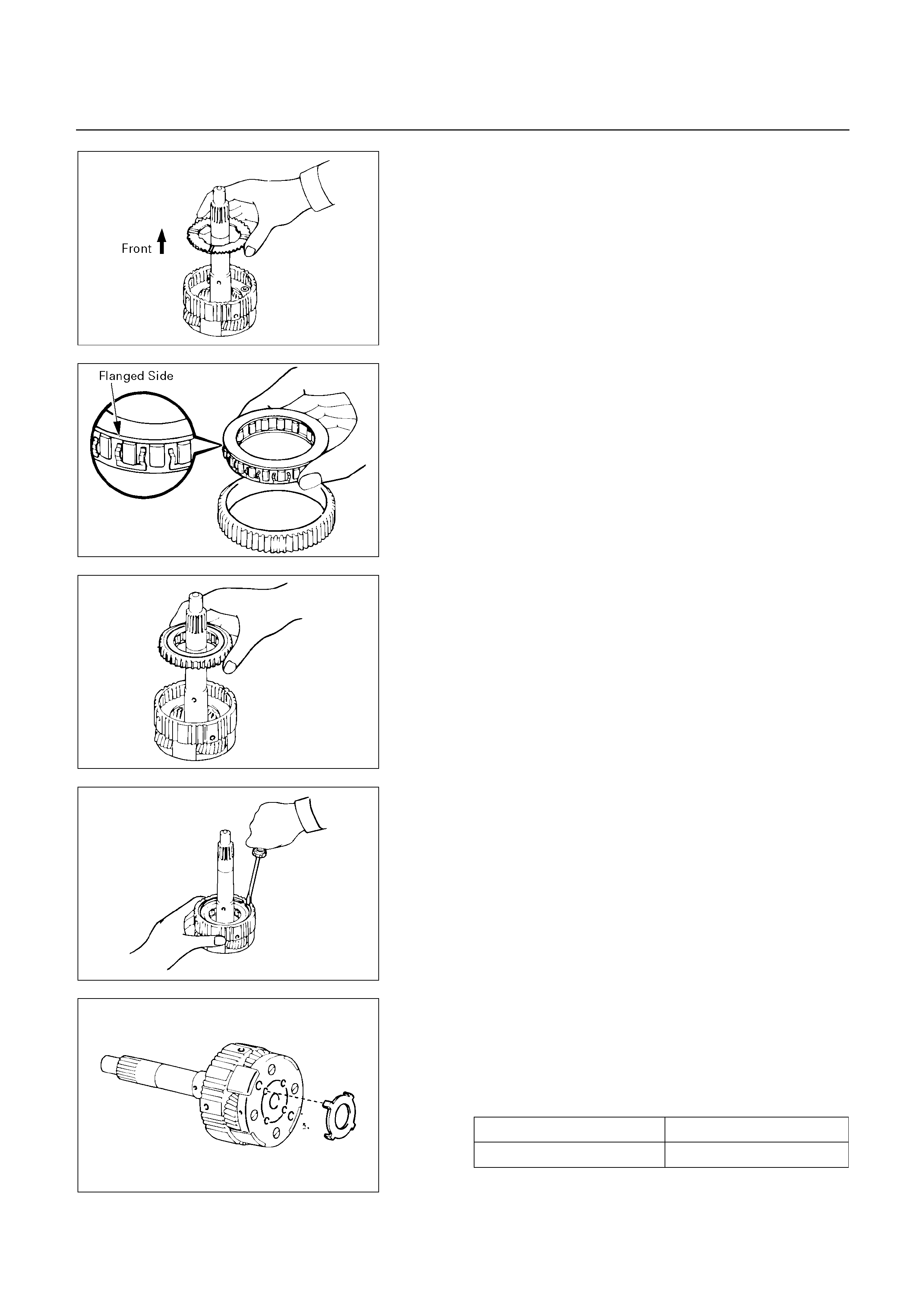
252RY00032
Reassembly steps
1. OD planetary gear assembly
2. Thrust washer
Install the thrust washer to the OD planetary gear,
facing the grooved side upward.
252RY00033
3. OD one-way clutch
Install the one-way clutch into the outer race, with the
flanged side of the one-way clutch facing upward.
252RY00026
Install OD one-way clutch with outer race to overdrive
planetary gear.
252RY00024
4. Retaining plate
5. Snap ring
Install retaining plate, then install snap ring, using a
screwdriver.
6. Race
Coat the race with petroleum jelly and install it to the
planetary gear.
Race diameter (Reference)
Inside diameter 27.3 mm (1.075 in)
Outside diameter 41.8 mm (1.646 in)
252RY00034
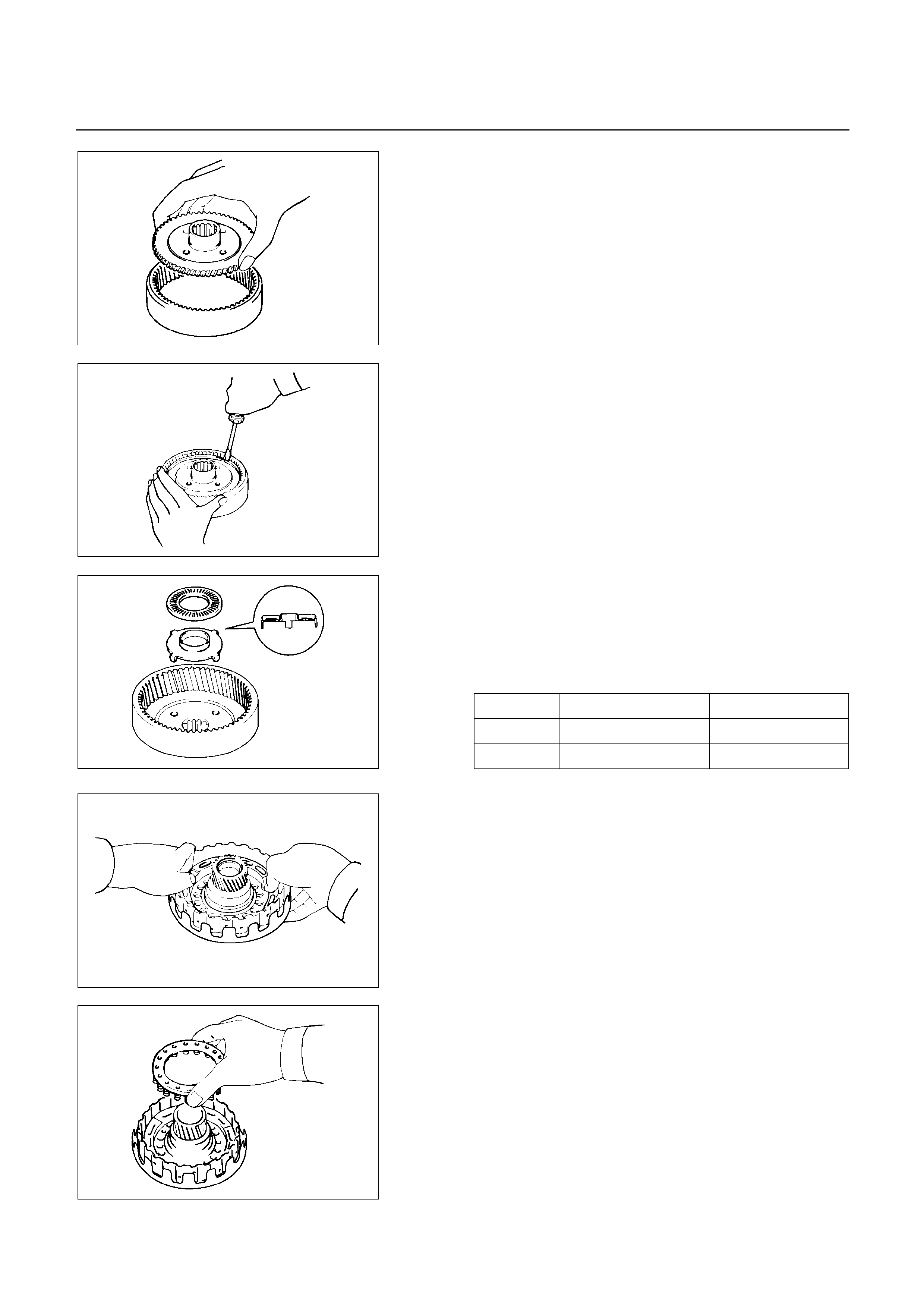
252RY00023
7. OD planetary ring gear
8. Ring gear flange
Install ring gear flange to OD planetary ring gear.
252RY00022
9. Snap ring
Install snap ring, using a screwdriver.
10. Thrust bearing
Coat the race and bearing with petroleum jelly and
install them onto the OD planetary ring gear.
Race and bearing diameter (Reference)
Inside Outside
Race 24.2 mm (0.953 in) 47.8 mm (1.882 in)
Bearing 26.0 mm (1.024 in) 46.8 mm (1.843 in)
252RY00035
252L100011
11. O-ring
Coat new O-rings with ATF and install them on the OD
direct clutch piston.
12. OD direct clutch piston with O-ring
Being careful not to damage the O-rings, press in the
OD direct clutch piston into the clutch drum, using both
hands.
252L100012
13. Piston return spring
Install piston return spring.
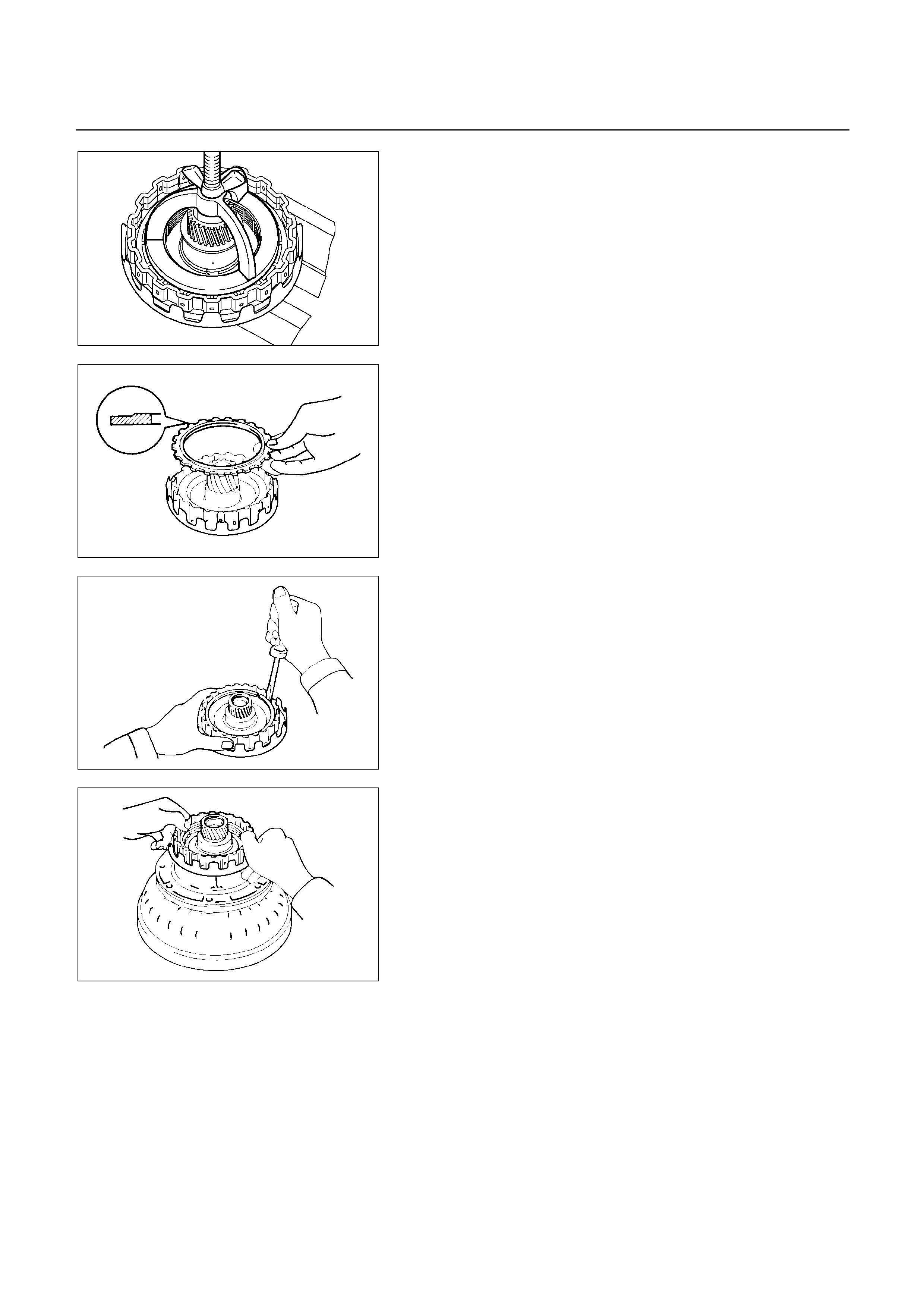
252L100007
14. Snap ring
Place special tool on the spring retainer, and compress
the return spring.
Spring compressor : 5-8840-0195-0 (J-23327-1)
Install the snap ring with snap ring pliers.
Be sure the end gap of the snap ring is not aligned with
the spring retainer claw.
252L100013
15. Flange, disc and plate
Install two plates and tow discs then install the flange,
with the flat side facing downward.
252L100014
16. Snap ring
Install snap ring.
252L100005
Check piston stroke of OD direct clutch (C-0)
Place the oil pump onto the torque converter, and then
place the OD direct clutch assembly onto the oil pump.
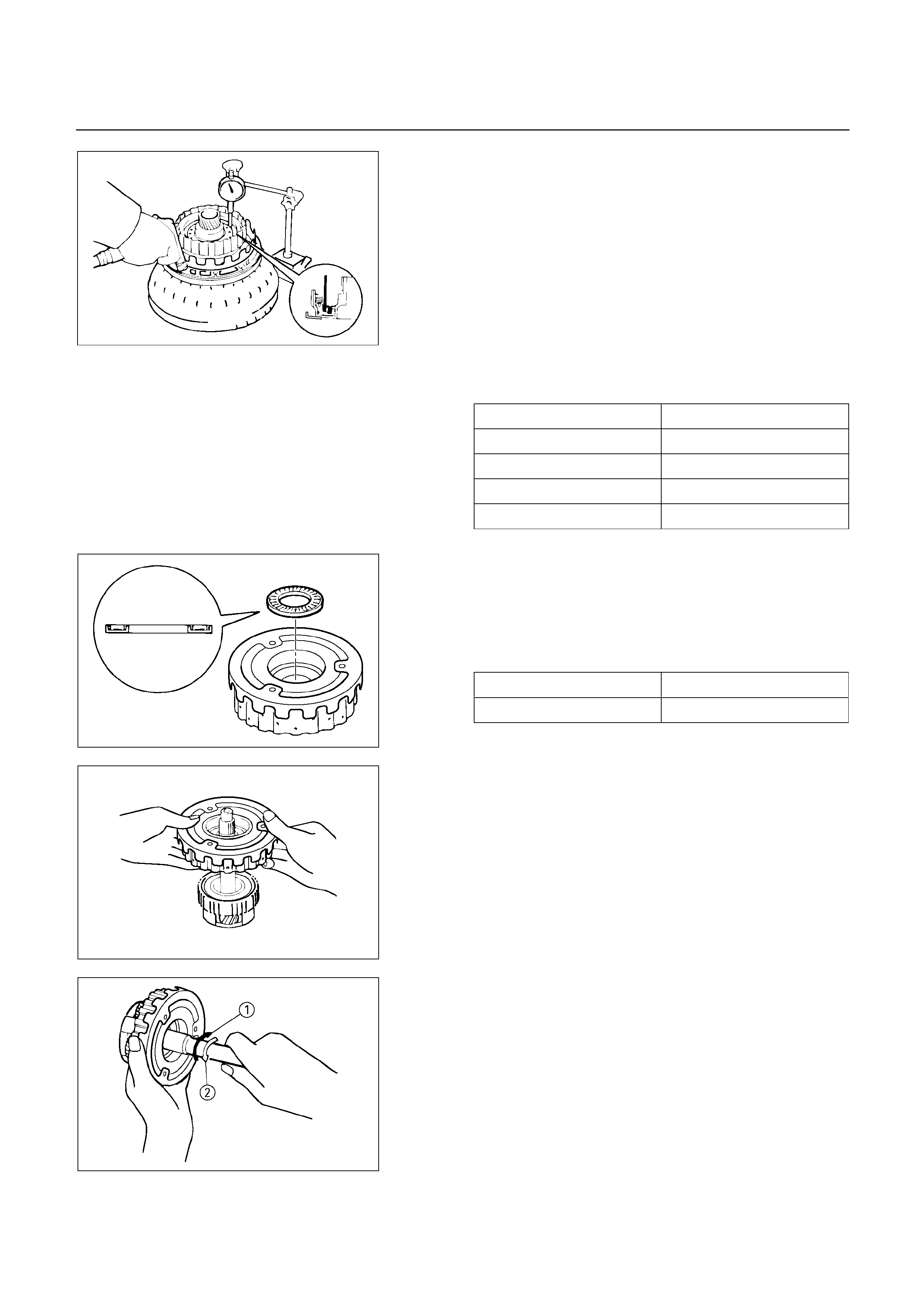
Using a dial indicator, measure the OD direct clutch
piston stroke by applying and releasing the compressed
air (390 – 780 kPa, 4 – 8 kg/cm2 or 57 – 114 psi) as
shown.
Piston stroke: 1.85 – 2.15 mm (0.0729 – 0.0847 in)
If the piston stroke is not within specification, replace
the disc and recheck the piston stroke.
If the piston stroke is non standard, select anothe
r
flange.
Flange sizes
Flange thickness Flange thickness
3.8 mm (0.150 in) 3.4 mm (0.134 in)
3.7 mm (0.146 in) 3.3 mm (0.130 in)
3.6 mm (0.142 in) 3.2 mm (0.126 in)
3.5 mm (0.138 in) 3.1 mm (0.122 in)
252L100016
17. Thrust bearing
Coat the assembled bearing and race with petroleum
jelly and install it with the race side facing downward.
Bearing and race (Reference)
Inside diameter 28.9 mm (1.138 in)
Outside diameter 50.2 mm (1.976 in)
252L100015
252L100004
18. OD direct clutch assembly
Align the flukes of discs in the direct clutch.
Install the OD direct clutch assembly onto the OD
planetary gear.
252L100003
Check operation of one-way clutch
Hold the OD direct clutch drum and turn the input shaft.
The input shaft should turn freely clockwise and should
lock counterclockwise.
1 : Free
2 : Lock
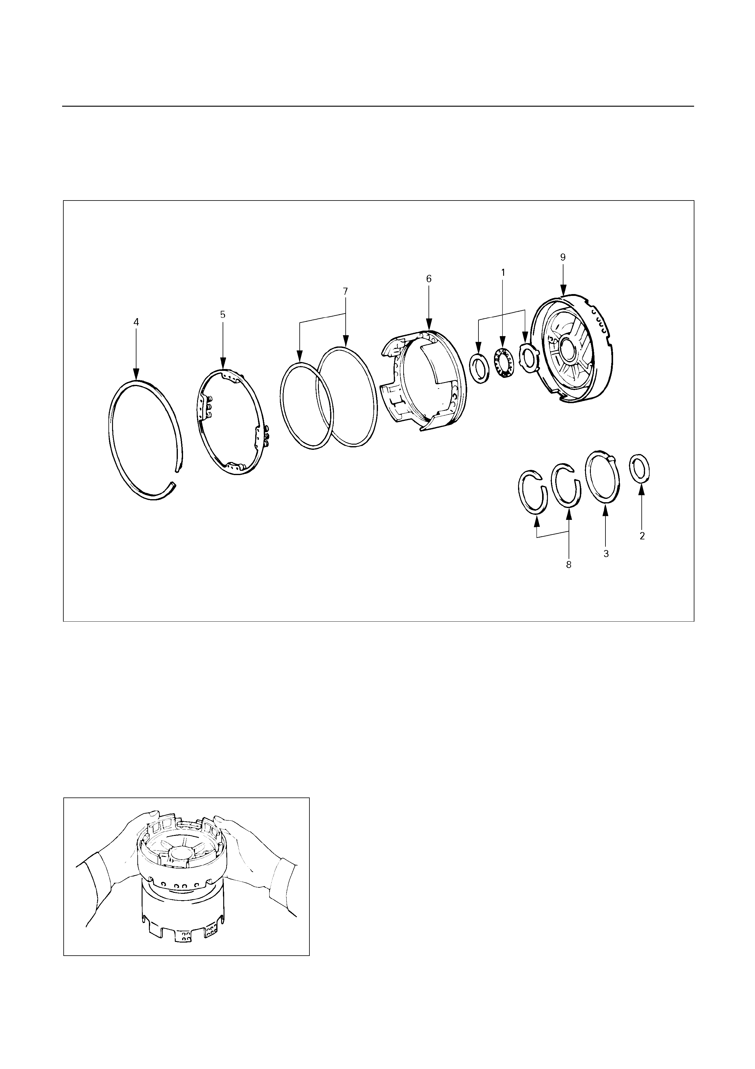
OD SUPPORT ASSEMBLY
DISASSEMBLY
252R200003
Disassembly steps
1. Thrust bearing
2. Race
3. Thrust washer (plastic)
4. Snap ring
5. Piston return spring
6. OD brake piston
7. O-ring
8. Oil seal ring
9. OD support
252RY00042
Disassembly steps
Check OD brake piston movement
Place the OD support assembly onto the direct clutch
assembly.
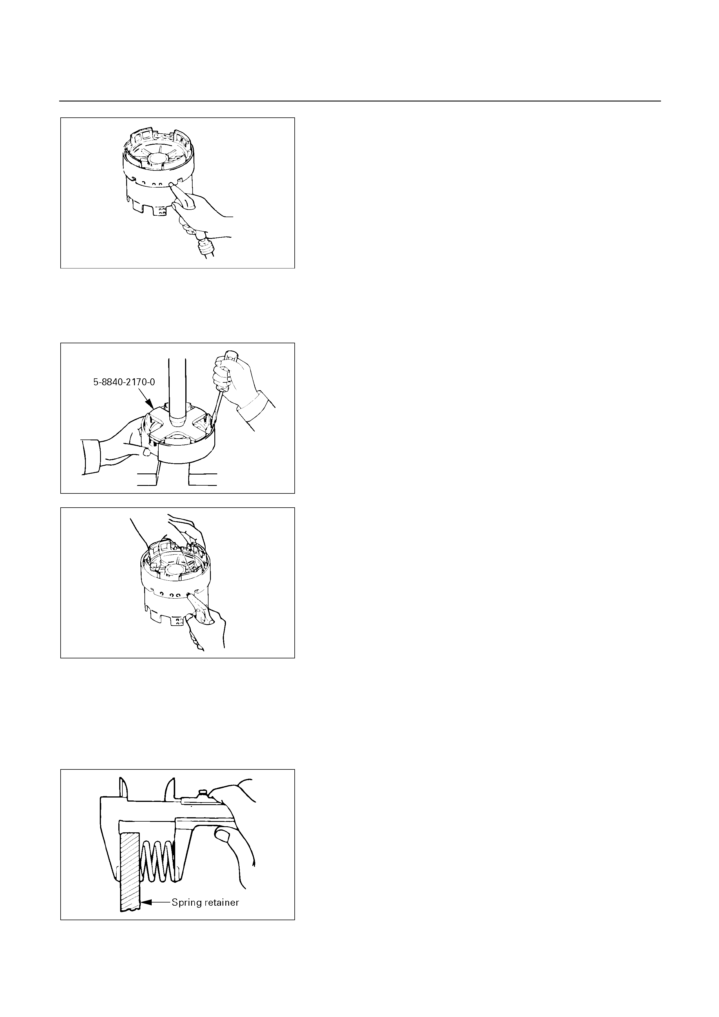
252RY00043
Apply compressed air into the oil passage as shown,
and be sure that the OD brake piston moves smoothly.
1. Thrust bearing
2. Race
3. Thrust washer (plastic)
252RY00044
4. Snap ring
Place special tool on the spring retainer, and compress
the return spring with a shop press.
Spring compressor : 5-8840-2170-0 (J-37233)
Remove the snap ring with a screwdriver.
5. Piston return spring
252RY00045
6. OD brake piston
Place the OD support onto the direct clutch assembly.
Hold the OD brake piston so it is not slanted and appl
y
compressed air into the passage to remove the OD
brake piston.
Remove the OD brake piston.
7. O-ring
8. Oil seal ring
9. OD support
INSPECTION AND REPAIR
Make necessary correction or parts replacement i
f
wear, damage or any abnormal conditions are found
through inspection.
252RY00046
Check piston return spring
Using calipers, measure the free length of the return
spring.
Standard length: 17.2 mm (0.677 in)
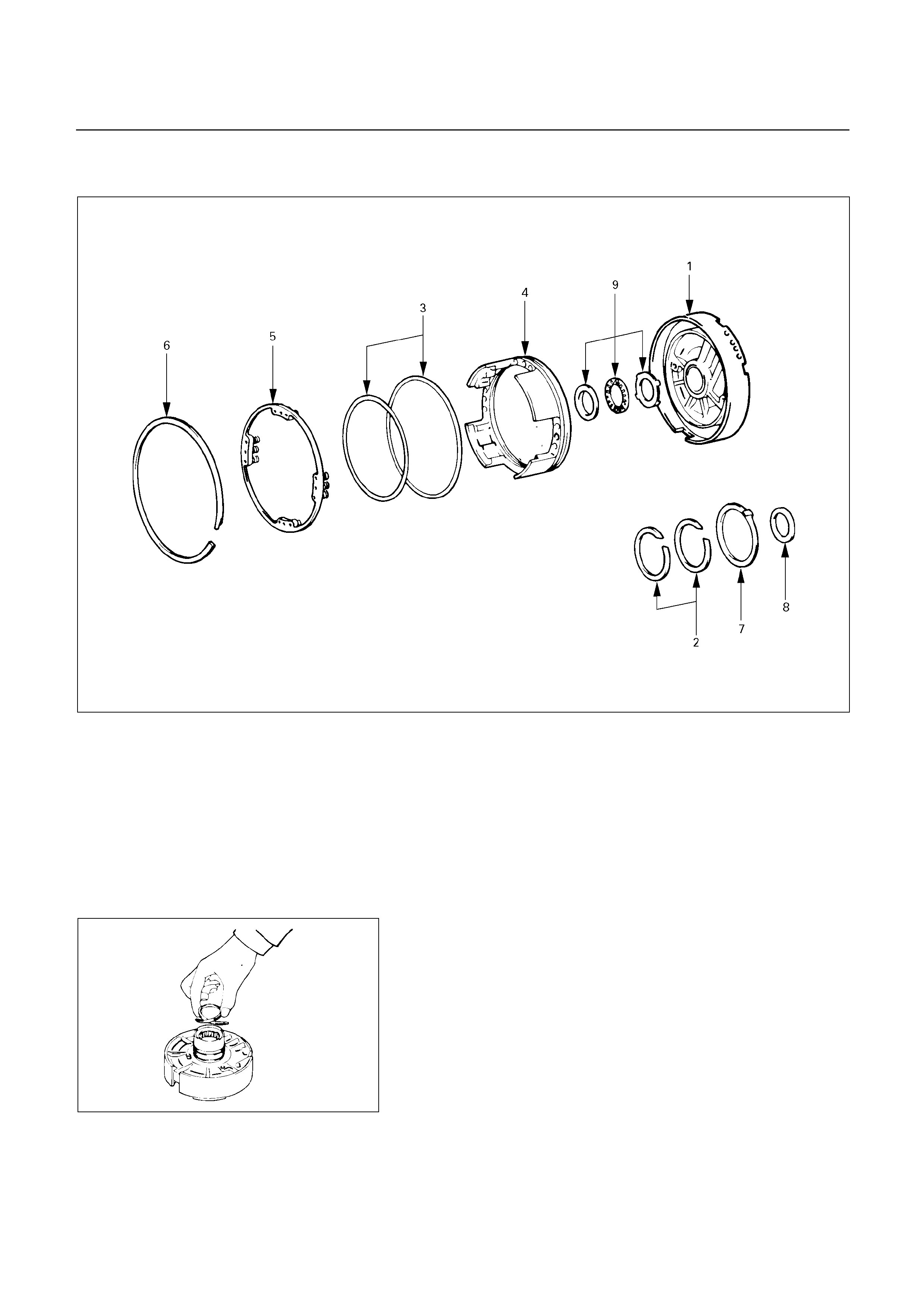
REASSEMBLY
252R200004
Reassembly steps
1. OD support
2. Oil seal ring
3. O-ring
4. OD brake piston
5. Piston return spring
6. Snap ring
7. Thrust washer (Plastic)
8. Race
9. Thrust bearing
252RY00047
Reassembly steps
1. OD support
2. Oil seal ring
Coat the two oil seal rings with ATF.
Contract the oil seals as shown, and install them onto
the OD support.
NOTE :
Do not spread the ring ends more than necessary.
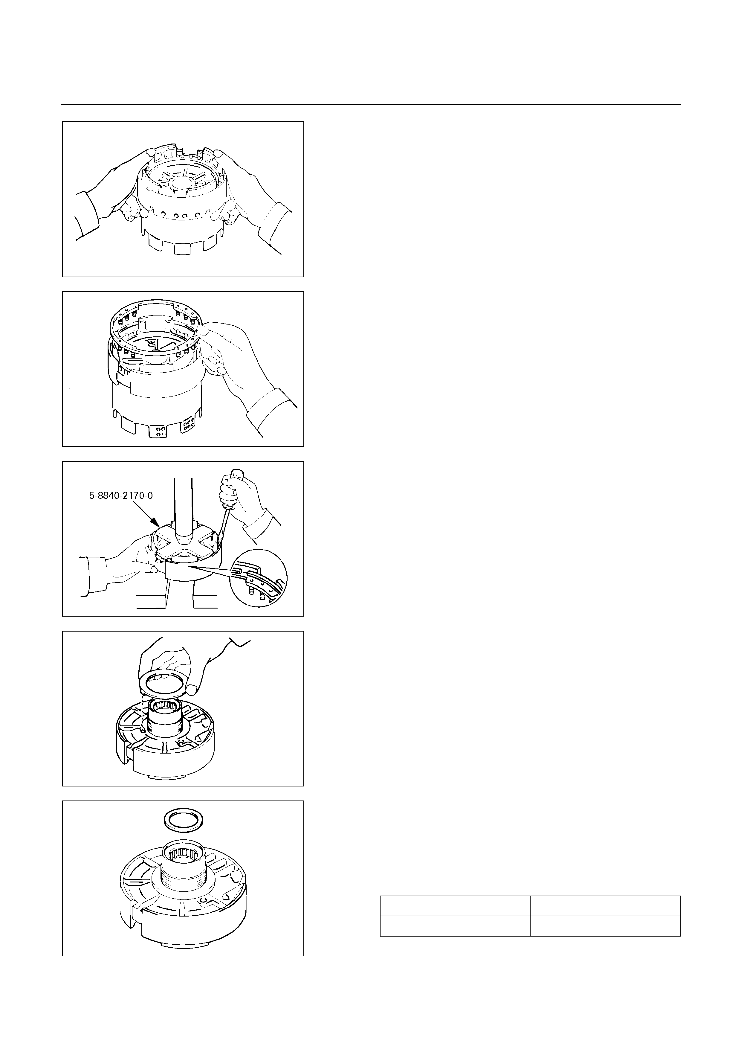
252RY00048
3. O-ring
Coat two new O-rings with ATF and install them on the
OD brake piston.
4. OD brake piston
Being careful not to damage the O-rings, press in the
brake piston into the OD support, using both hands.
252RY00049
5. Piston return spring
Install piston return spring.
252RY00050
6. Snap ring
Place special tool on the spring retainer, and compress
the return spring with a shop press.
Spring compressor : 5-8840-2170-0 (J-37233)
Install the snap ring with a screwdriver.
Be sure the end gap of the snap ring is not aligned with
cutout portion of the OD support.
252RY00051
7. Thrust washer (plastic)
Coat the thrust washer with petroleum jelly and install it
onto the OD support.
NOTE :
Make sure that the lug fits into the hole on the OD
support.
8. Race
Coat the race with petroleum jelly, and install it onto the
OD support.
Race diameter (Reference)
Inside diameter 36.8 mm (1.450 in)
Outside diameter 50.9 mm (2.004 in)
252RY00052
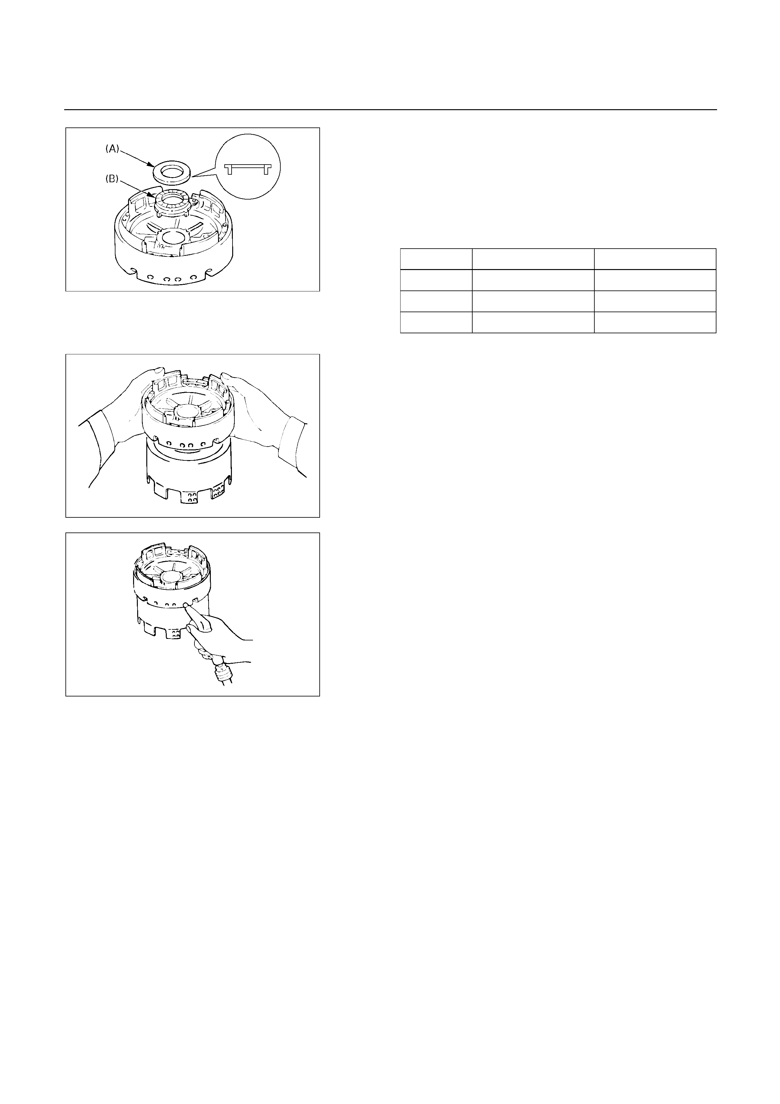
9. Thrust bearing
Turn over OD support.
Coat the two races with petroleum jelly, and install them
onto the OD support.
Race and bearing diameter (Reference)
Inside Outside
Race (A) 37.2 mm (1.465 in) 58.8 mm (2.315 in)
Bearing 36.5 mm (1.437 in) 48.4 mm (1.906 in)
Race (B) 33.7 mm (1.327 in) 50.1 mm (1.972 in)
252RY00069
252RY00042
Check OD brake piston movement
Place the OD support assembly onto the direct clutch
assembly.
252RY00043
Apply compressed air into the oil passage as shown,
and be sure that the OD brake piston moves smoothly.
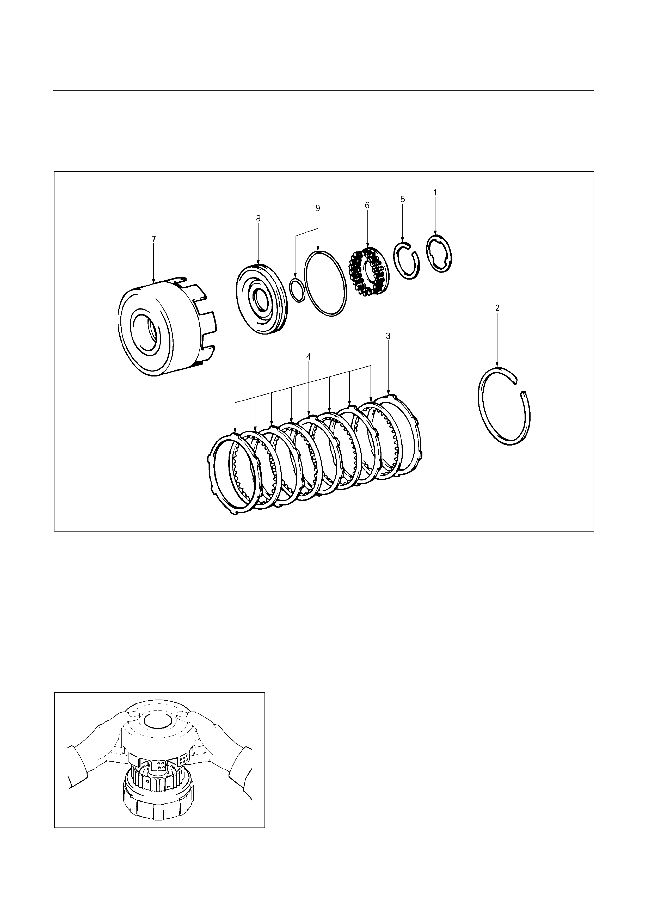
DIRECT CLUTCH ASSEMBLY (C-2)
DISASSEMBLY
248R200001
Disassembly steps
1. Clutch drum thrust washer (Plastic)
2. Snap ring
3. Flange
4. Plate and disc
Five plates and five discs (UBS)
Four plates and four discs (TFR/S)
5. Snap ring
6. Piston return spring
7. Direct clutch drum
8. Direct clutch piston
9. O-ring
248RY00028
Disassembly steps
Remove direct clutch drum assembly from forward
clutch assembly.
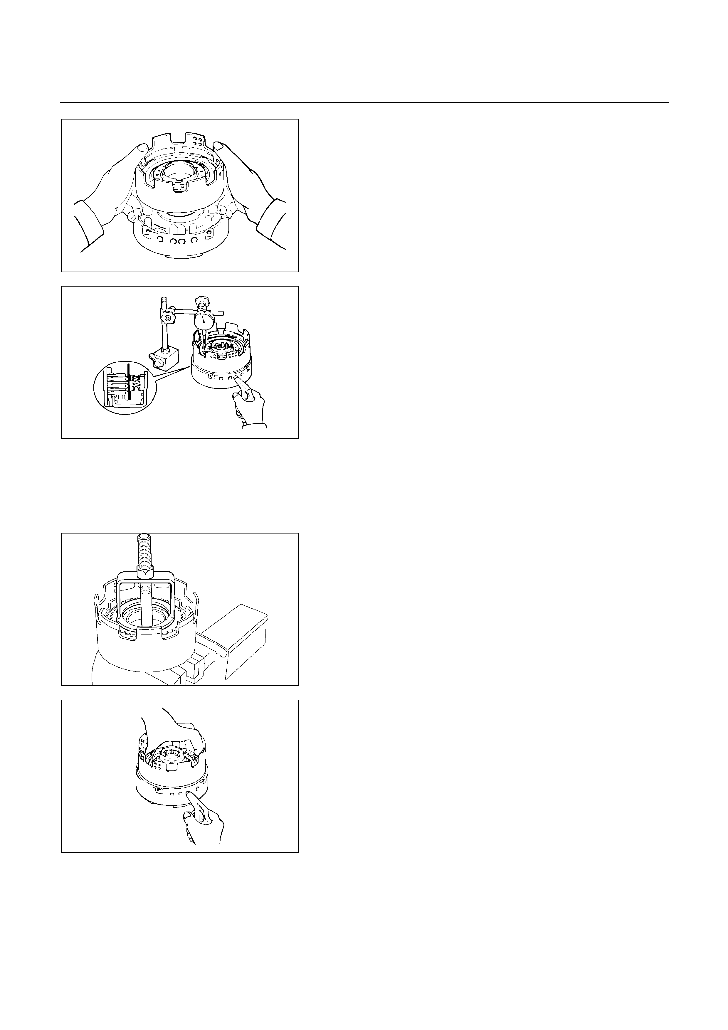
248RY00029
Check piston stroke of direct clutch (C-2)
Place the direct clutch assembly onto the OD support
assembly.
248RY00061
Using a dial indicator, measure the direct clutch piston
stroke by applying and releasing compressed air (390 –
780 kPa, 4 – 8 kg/cm2 or 57 – 114 psi) as shown.
Piston stroke: 1.6 – 1.9 mm (0.0630 – 0.0748 in)
(UBS)
Pack clearance: 0.4 – 0.7 mm (0.0157 – 0.0276 in)
(TFR/S)
1. Clutch drum thrust washer (Plastic)
2. Snap ring
3. Flange
4. Plate and disc
248RY00002
5. Snap ring
Place special tool on the spring retainer and compress
the return spring.
Using snap ring pliers, remove the snap ring.
Spring compressor : 5-8840-0254-0 (J-25048)
6. Piston return spring
248RY00030
7. Direct clutch drum
8. Direct clutch piston
9. O-ring
Place the direct clutch drum onto the OD support.
Holding the direct clutch piston by hand, appl
y
compressed air to the OD support to remove the direct
clutch piston.
Remove the direct clutch piston.
Remove two O-rings from piston.
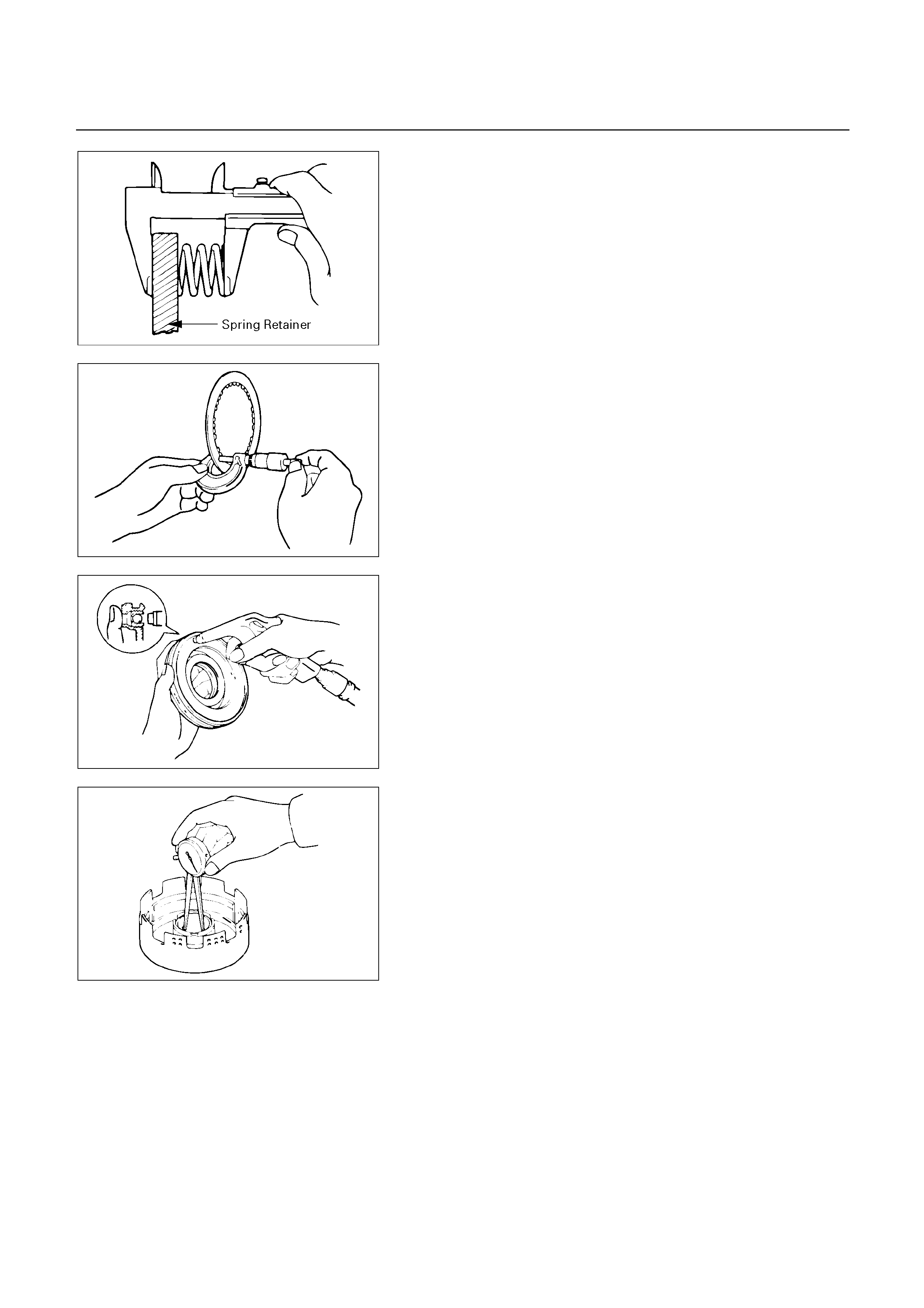
247RY00034
INSPECTON AND REPAIR
Check piston return spring
Using calipers, measure the free length of the return
spring.
Standard length: 21.3 mm (0.839 in)
252RY00027
Check discs
Using micrometer, measure the thickness of the discs.
Minimum thickness: 1.84 mm (0.0724 in)
If the thickness is less than the minimum, replace the
disc.
248RY00031
Check direct clutch piston
Check that check ball is free by shaking the piston.
Check that the valve does not leak by applying low-
pressure compressed air.
248RY00032
Check direct clutch drum bushing
Using a dial indicator, measure the inside diameter o
f
the clutch drum bushing.
Maximum inside diameter: 53.99 mm (2.1256 in)
If the inside diamater is greater than the maximum,
replace the clutch drum.

REASSEMBLY
248R200002
Reassembly steps
1. O-ring
2. Direct clutch piston
3. Direct clutch drum
4. Piston return spring
5. Snap ring
6. Disc and plate
Five discs and five plates (UBS)
Four discs and four plates (TFR/S)
7. Flange
8. Snap ring
9. Clutch drum thrust washer (Plastic)
248RY00033
Reassembly steps
1. O-ring
2. Direct clutch piston
3. Direct clutch drum
Coat new O-rings with ATF and install them on the
direct clutch piston.
Install direct clutch piston to direct clutch drum.
Being careful not to damage the O-rings, press in the
direct clutch piston into the clutch drum, using both
hands.
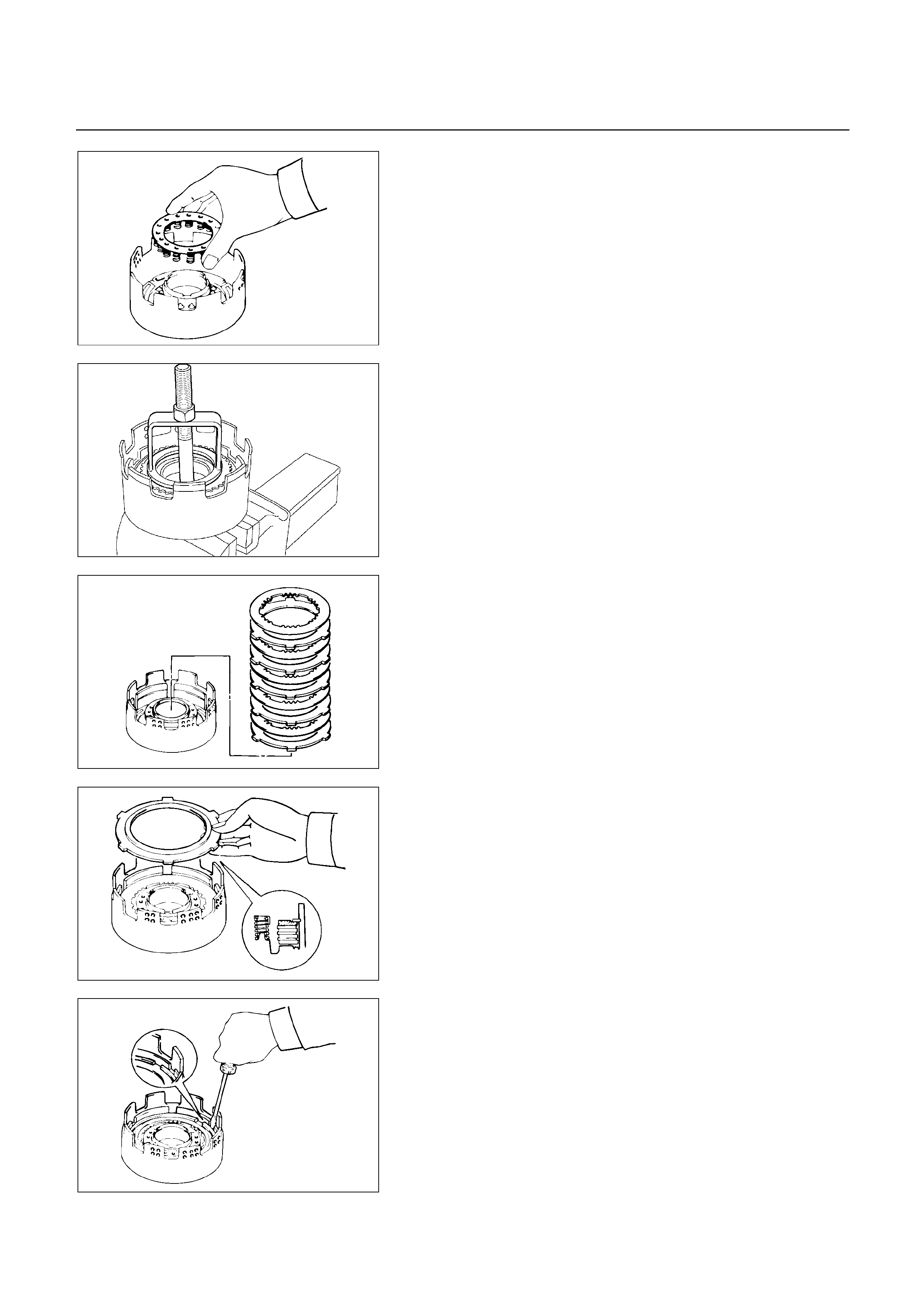
248RY00034
4. Piston return spring
Install piston return spring.
248RY00002
5. Snap ring
Compress piston return spring and install snap ring in
groove.
Place special tool on the spring retainer, and compress
the return spring.
Install the snap ring with snap ring pliers.
Be sure the end gap of the snap ring is not aligned with
the spring retainer claw.
Spring compressor: 5-8840-0254-0 (J-25048)
248RY00062
6. Disc and plate
Install plates and discs.
Install in order : P-D-P-D-P-D-P-D-P-D (UBS)
: P-D-P-D-P-D-P-D (TFR/S)
P : Plate, D : Disc
248RY0035
7. Flange
Install the flange, with the flat side facing downward.
248RY00036
8. Snap ring
Install the snap ring with a screwdriver.
Be sure the end gap of the snap ring is not aligned with
the cutout portion of the direct clutch drum.
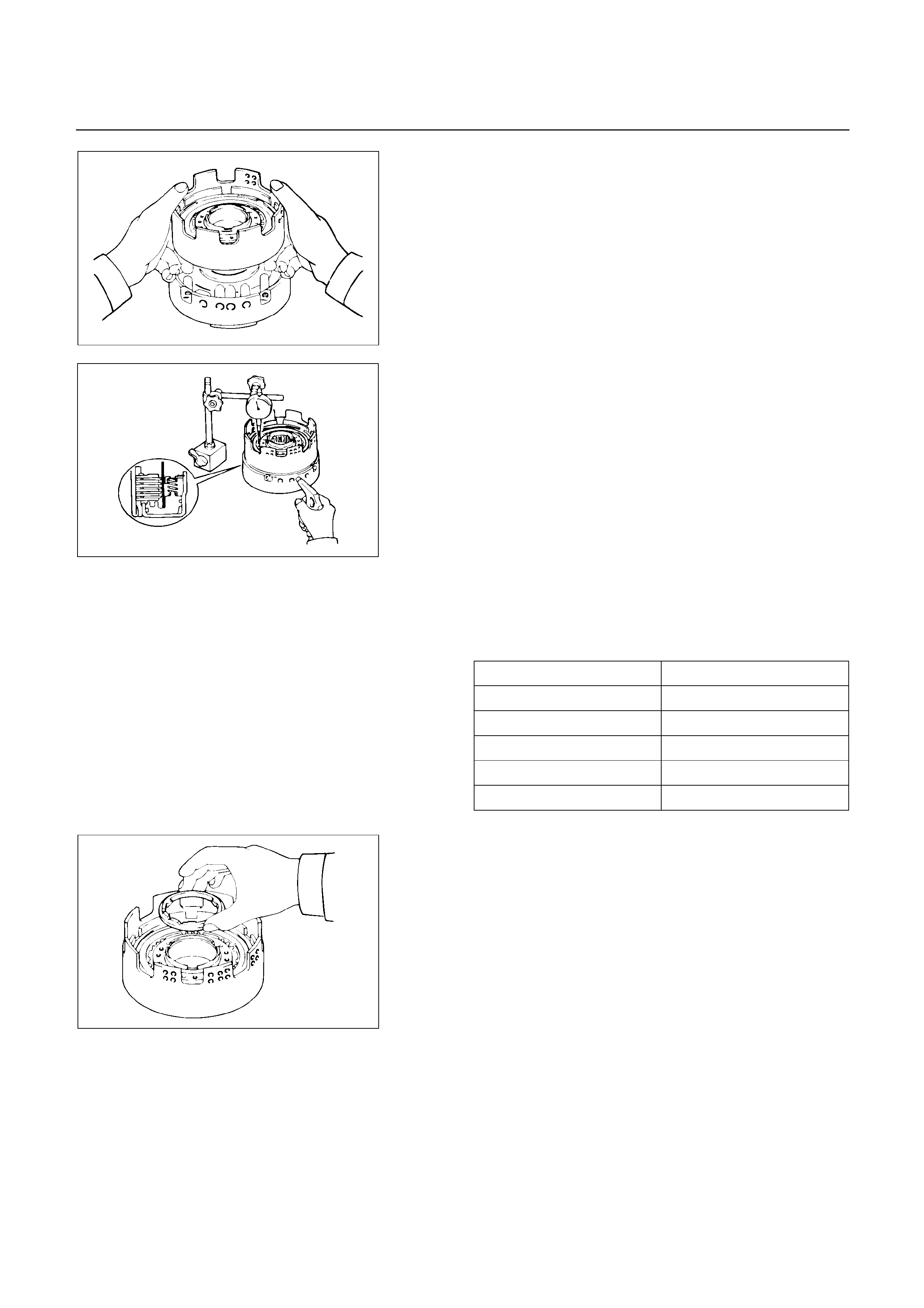
248RY00029
Check piston stroke of direct clutch (C-2)
Place the direct clutch assembly onto the OD support
assembly.
Using a dial indicator, measure the direct clutch piston
stroke by applying and releasing compressed air (390 –
780 kPa, 4 – 8 kg/cm2 or 57 – 114 psi) as shown.
Piston stroke: 1.6 – 1.9 mm (0.0630 – 0.0748 in)
(UBS)
Pack clearance: 0.4 – 0.7 mm (0.0157 – 0.0276 in)
(TFR/S)
If the piston stroke is not within specification, replace
the discs and recheck the piston stroke.
If the piston stroke is non standard, select anothe
r
flange.
Flange sizes
Flange thickness Flange thickness
3.3 mm (0.130 in) 3.8 mm (0.150 in)
3.4 mm (0.134 in) 3.9 mm (0.154 in)
3.5 mm (0.138 in) 4.0 mm (0.157 in)
3.6 mm (0.142 in) 4.1 mm (0.161 in)
3.7 mm (0.146 in) 4.2 mm (0.165 in)
248RY00061
248RY00037
9. Clutch drum thrust washer (plastic)
Coat the thrust washer with petroleum jelly and install it
onto the direct clutch.
NOTE :
Make sure that the lugs fit into the cutout portions
on the direct clutch.

248RY00038
Align the flukes of discs in the direct clutch.
Install the direct clutch assembly onto the forward clutch
assembly.
Check that the distance from the direct clutch end to the
forward clutch end is 71.2 mm (2.803 in).
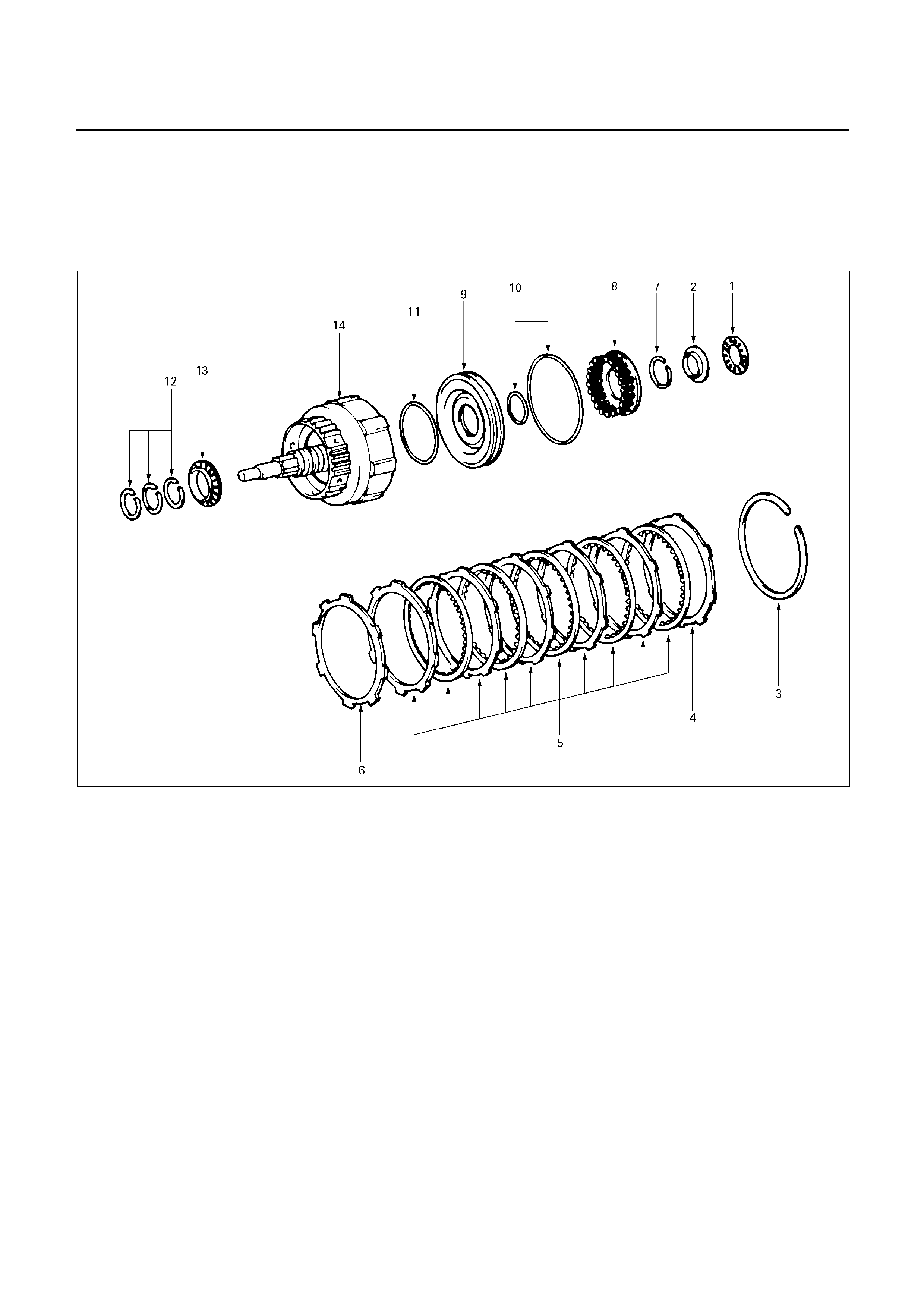
FORWARD CLUTCH ASSEMBLY (C-1)
DISASSEMBLY
248R200003
Disassembly steps
1. Thrust bearing
2. Race
3. Snap ring
4. Flange
5. Disc and plate
Six discs and six plates (UBS)
Five discs and five plates (TFR/S)
6. Cushion plate
7. Snap ring
8. Piston return spring
9. Piston
10. O-ring
11. O-ring
12. Oil seal ring
13. Thrust bearing
14. Forward clutch drum
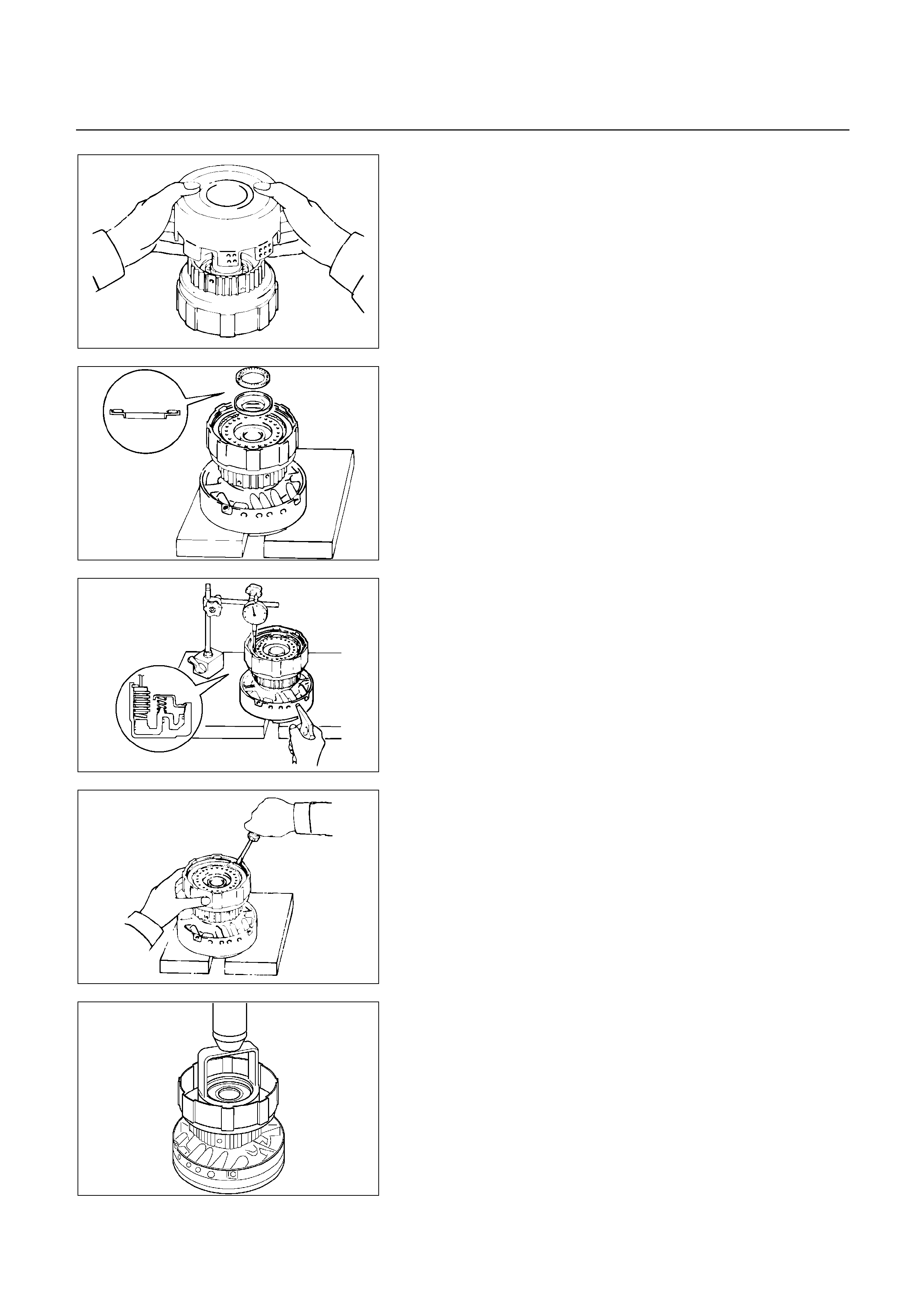
248RY00039
Disassembly steps
Remove forward clutch assembly from direct clutch
assembly.
248RY00048
1. Thrust bearing
2. Race
Place wooden blocks, etc. to prevent forward clutch
shaft from touching the work stand, and place the OD
support on them.
Place the forward clutch onto the OD support and
remove the bearing and race.
248R200008
Check piston stroke of forward clutch (C-1)
Using a dial indicator, measure the forward clutch
piston stroke by applying and releasing compressed ai
r
(390 – 780 kPa, 4 – 8 kg/cm2 or 57 – 114 psi) as
shown.
Pack clearance: 0.6 – 1.0 mm (0.0236 – 0.0394 in)
(UBS)
: 0.5 – 0.9 mm (0.0197 – 0.0354 in)
(TFR/S)
248RY00041
3. Snap ring
Remove snap ring from clutch drum.
4. Flange
5. Disc and plate
6. Cushion plate
248RY00003
7. Snap ring
Place special tool on the sparing retainer and compress
the return spring.
Using snap ring pliers, remove the snap ring.
Spring compressor : 5-8840-0254-0 (J-25048)
8. Piston return spring
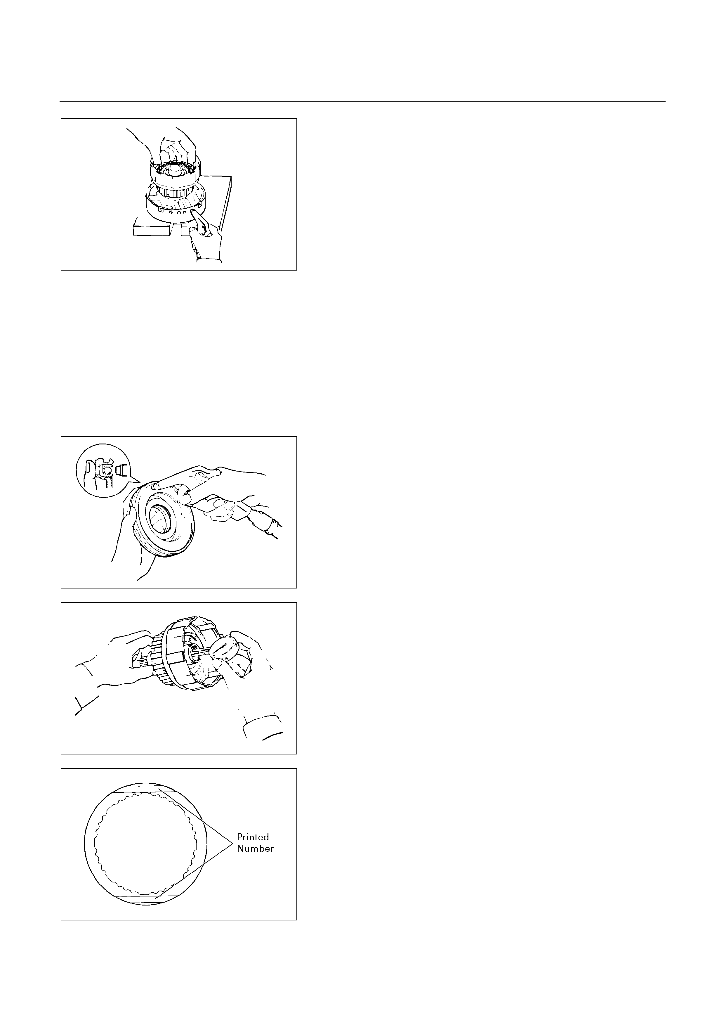
248RY00042
9. Piston
Place the forward clutch drum onto the OD support.
Holding the forward clutch piston by hand, appl
y
compressed air to the OD support to remove the
forward clutch piston.
10. O-ring
11. O-ring
12. Oil seal ring
13. Thrust bearing
14. Forward clutch drum
248RY00031
INSPECTION AND REPAIR
Check forward clutch piston
Check that check ball is free by shaking the piston.
Check that the valve does not leak by applying low-
pressure compressed air.
248RY00043
Check forward clutch drum bushing
Using a dial indicator, measure the inside diameter o
f
the forward clutch drum bushing.
Maximum inside diameter: 24.08 mm (0.948 in)
If the inside diameter is greater then the maximum,
replace the forward clutch drum.
248RY00045
Check disc, plate and flange
Check to see if the sliding surface of the disc, plate and
flange are worn or burnt. If necessary, replace them.
If the lining of the disc is peeling off or discolored, o
r
even if parts of the printed numbers are defaced,
replace all discs.
Before assembling new discs, soak them in ATF fo
r
at least fifteen minutes.

247RY00034
Check piston return spring
Using calipers, measure the free length of the return
spring.
Standard length: 19.47 mm (0.7665 in)
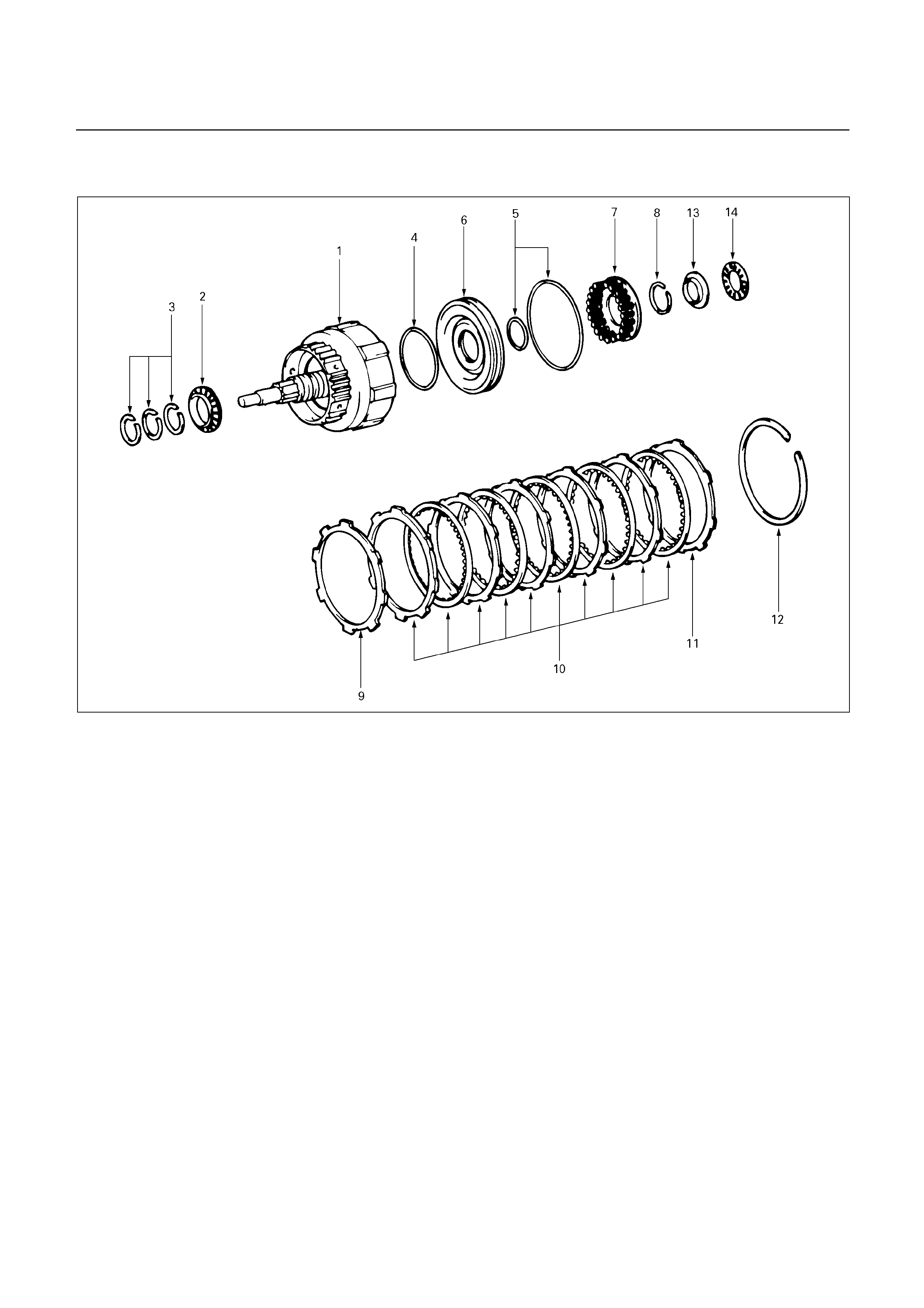
REASSEMBLY
248R200004
Reassembly steps
1. Forward clutch drum
2. Thrust bearing
3. Oil seal ring
4. O-ring
5. O-ring
6. Forward clutch piston
7. Piston return spring
8. Snap ring
9. Cushion plate
10. Disc and plate
Six discs and six plates (UBS)
Five discs and five plates (TFR/S)
11. Flange
12. Snap ring
13. Race
14. Thrust bearing
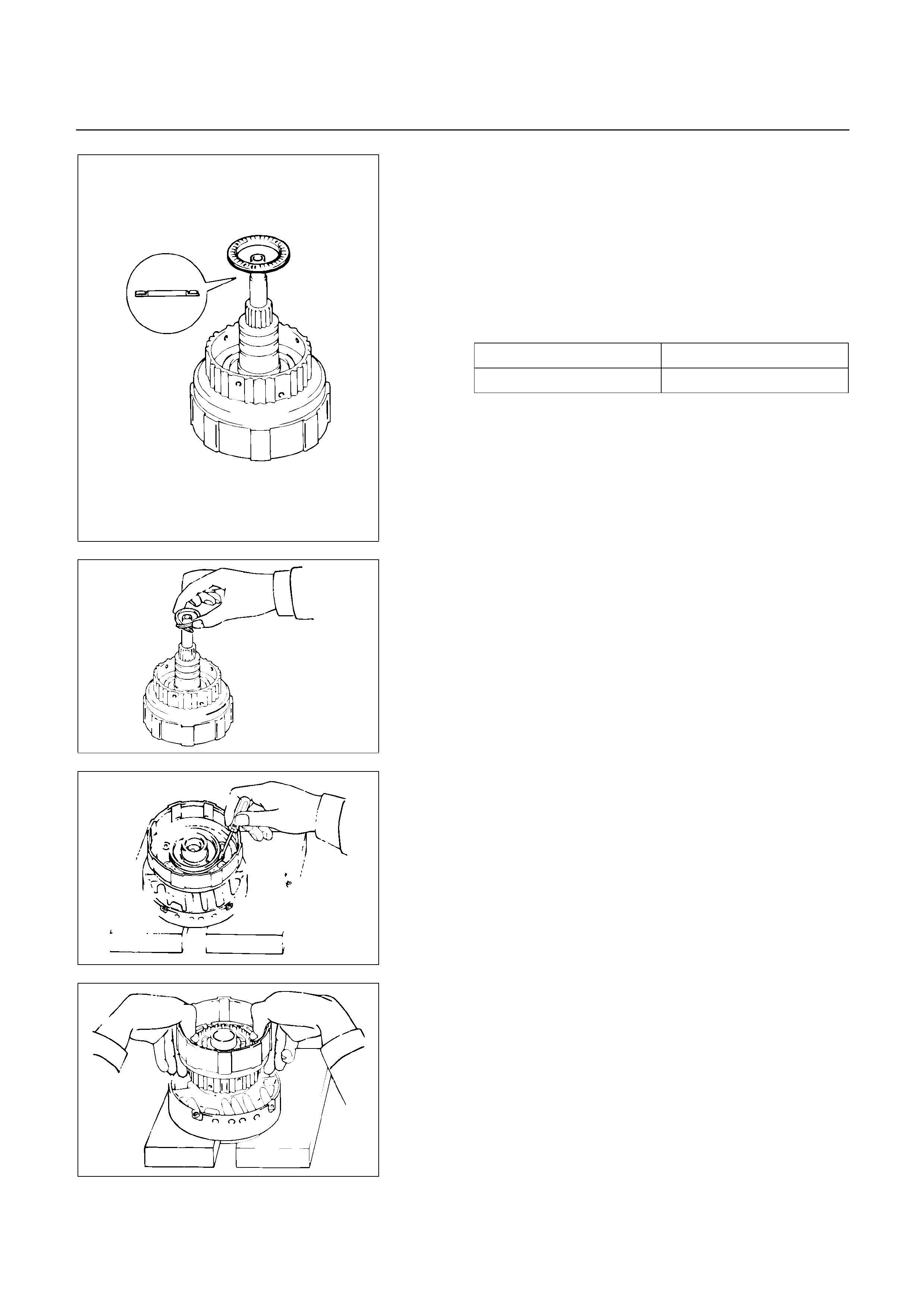
Reassembly steps
1. Forward clutch drum
2. Thrust bearing
Coat the assembled bearing and race with petroleum
jelly and install it onto the forward clutch drum, with the
race side facing downward.
Bearing and race (Reference)
Inside diameter 33.7 mm (1.327 in)
Outside diameter 47.8 mm (1.882 in)
248RY00044
248RY00046
3. Oil seal ring
Coat the three oil rings with ATF.
Contract the oil seal rings as shown, and install three oil
seal rings onto the forward clutch drum.
NOTE:
Do not spread the ring ends more than necessary.
248RY00047
4. O-ring
Coat a new O-ring with ATF and install O-ring on the
forward clutch drum.
5. O-ring
Coat new O-rings with ATF and install two O-rings on
the forward clutch piston.
248RY00049
6. Forward clutch piston
Being careful not to damage the O-rings, press the
forward clutch piston into the forward clutch drum.
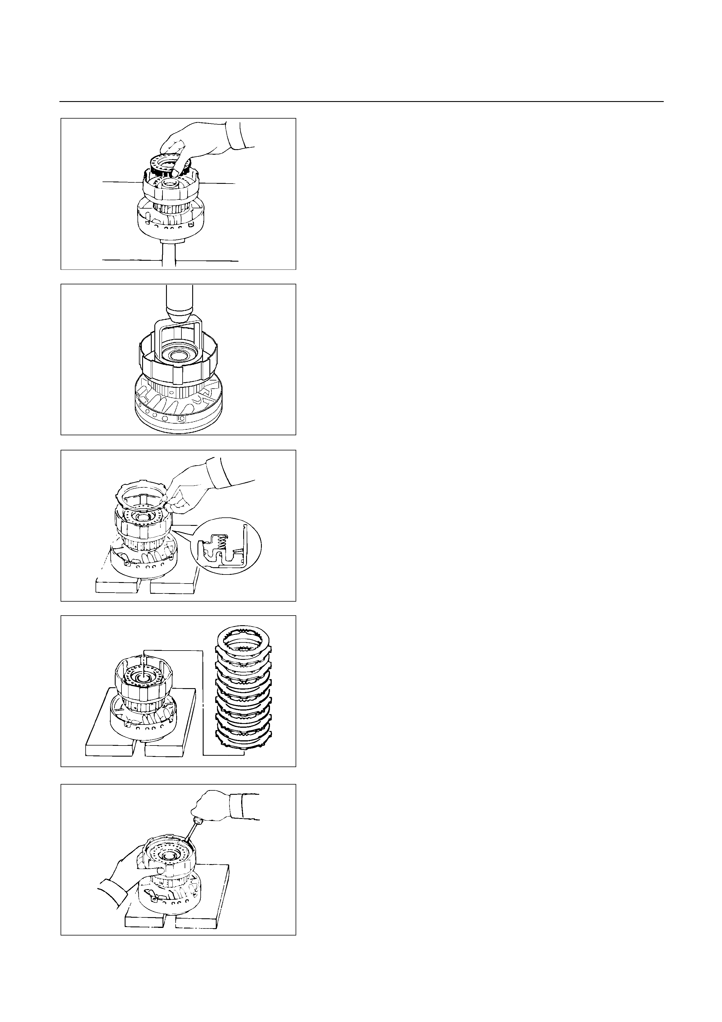
248RY00065
7. Piston return spring
Install piston return spring.
248RY00003
8. Snap ring
Place special tool on the spring retainer, and compress
the return spring.
Spring compressor: 5-8840-0245-0 (J-25048)
Install the snap ring with snap ring pliers.
Be sure the end gap of the snap ring is not aligned with
the spring retainer claw.
248RY00069
9. Cushion plate
Install cushion plate rounded side down as shown.
248RY00070
10. Disc and plate
Install discs and plates.
Install in order: P-D-P-D-P-D-P-D-P-D-P-D (UBS)
: P-D-P-D-P-D-P-D-P-D (TFR/S)
11. Flange
And then install the flange, with the rounded edge
facing downward.
248RY00041
12. Snap ring
Install the snap ring with a screwdriver.
Be sure the end gap of the snap ring is not aligned with
the cutout portion of the forward clutch drum.
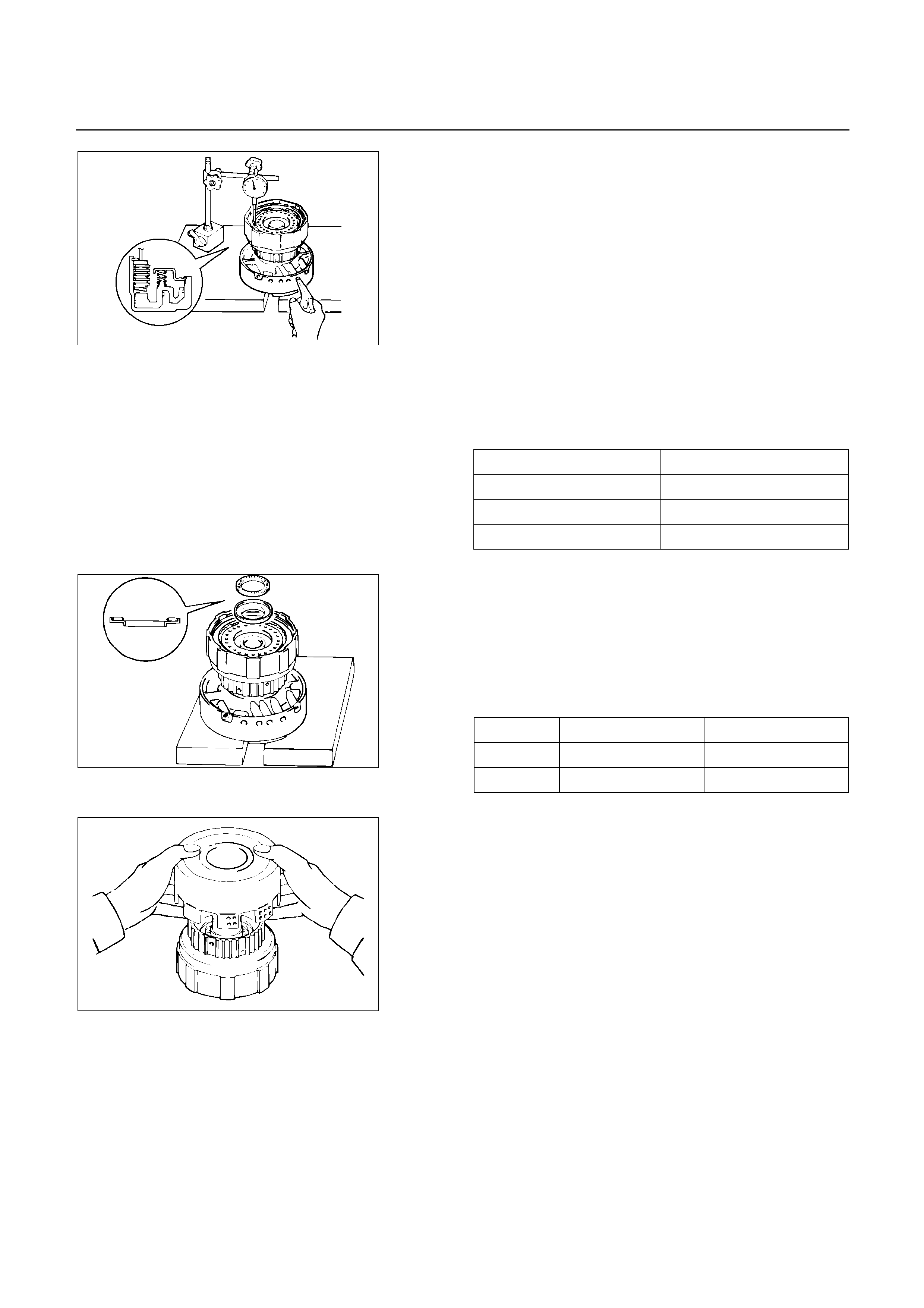
248R200008
Check piston stroke of forward clutch (C-1)
Using a dial indicator, measure the forward clutch
piston stroke by applying and releasing the compressed
air (380 – 780 kPa, 4 – 8 kg/cm2 or 57 – 114 psi) as
shown.
Pack clearance: 0.6 – 1.0 mm (0.0236 – 0.0394 in)
(UBS)
: 0.5 – 0.9 mm (0.0197 – 0.0354 in)
(TFR/S)
If the piston stroke is not within specification, replace
the discs, and recheck the piston stroke.
Available flange sizes
3.0 mm (0.118 in) 3.4 mm (0.134 in)
4.2 mm (0.165 in) 3.6 mm (0.142 in)
4.4 mm (0.173 in) 3.8 mm (0.150 in)
3.2 mm (0.126 in) 4.0 mm (0.158 in)
13. Race
14. Thrust bearing
Coat the race and bearing with petroleum jelly, and
install them onto the forward clutch drum.
Race and bearing diameter (Reference)
Inside Outside
Race 26.0 mm (1.024 in) 48.9 mm (1.925 in)
Bearing 26.0 mm (1.024 in) 46.7 mm (1.839 in)
248RY00048
248RY00039
Align the flukes of discs in the direct clutch.
Install the direct clutch assembly onto the forward clutch
assembly.

248RY00038
Check that the distance from the direct clutch end to the
forward clutch end is 71.2 mm (2.803 in).
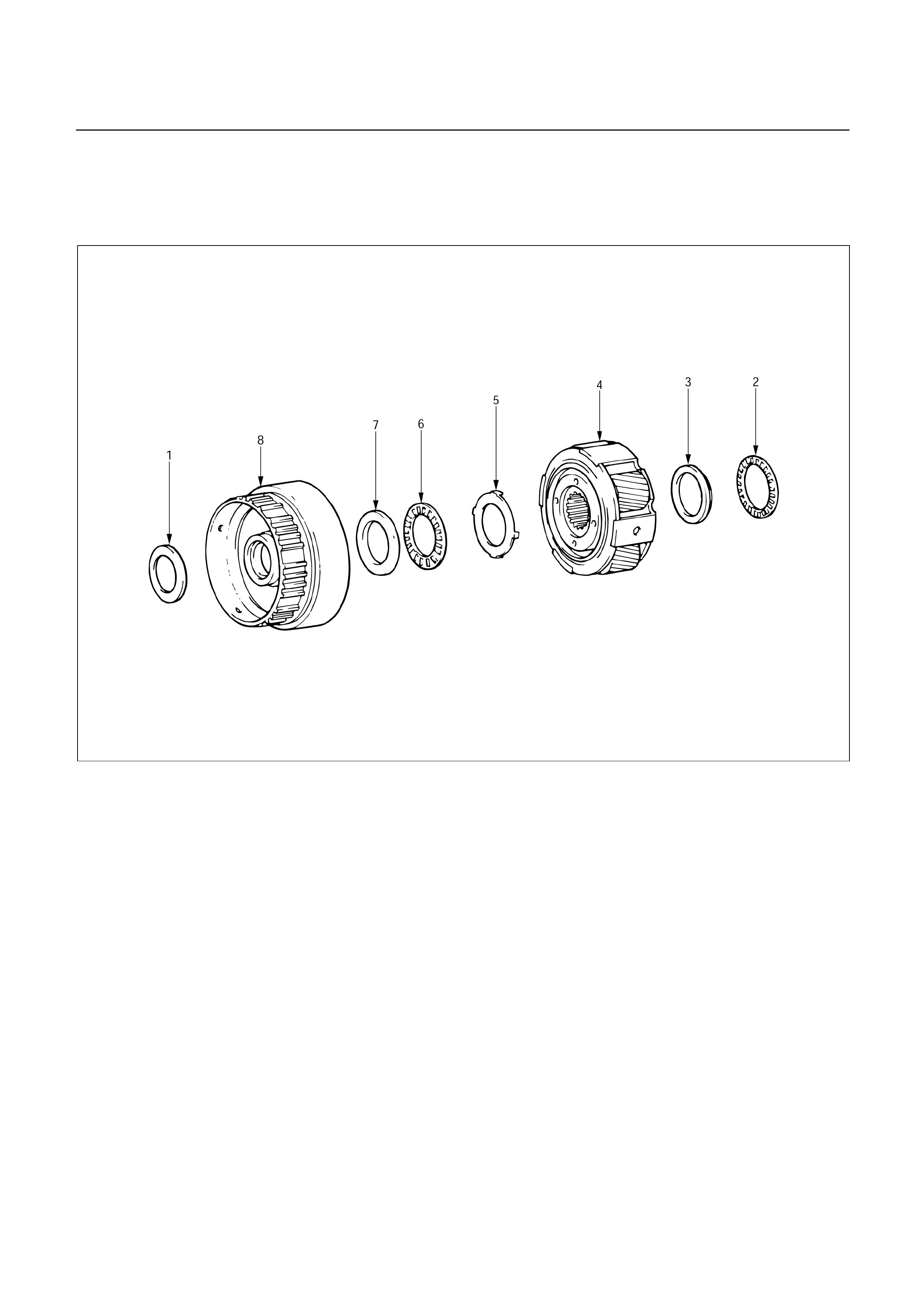
FRONT PLANETARY GEAR
DISASSEMBLY
247R200003
Disassembly steps
1. Race
2. Thrust bearing
3. Race
4. Front planetary gear
5. Race (Metal)
6. Thrust bearing
7. Race
8. Front planetary ring gear
Disassembly steps
1. Race
2. Thrust bearing
3. Race
4. Front planetary gear
5. Race (Metal)
6. Thrust bearing
7. Race
8. Front planetary ring gear

247RY00021
INSPECTION AND REPAIR
Check front planetary ring gear bushing
Using a dial indicator, measure the inside diameter o
f
the front planetary ring gear bushing.
Maximum inside diameter: 24.08 mm (0.9480 in)
If the inside diameter is greater than the maximum,
replace the front planetary ring gear.
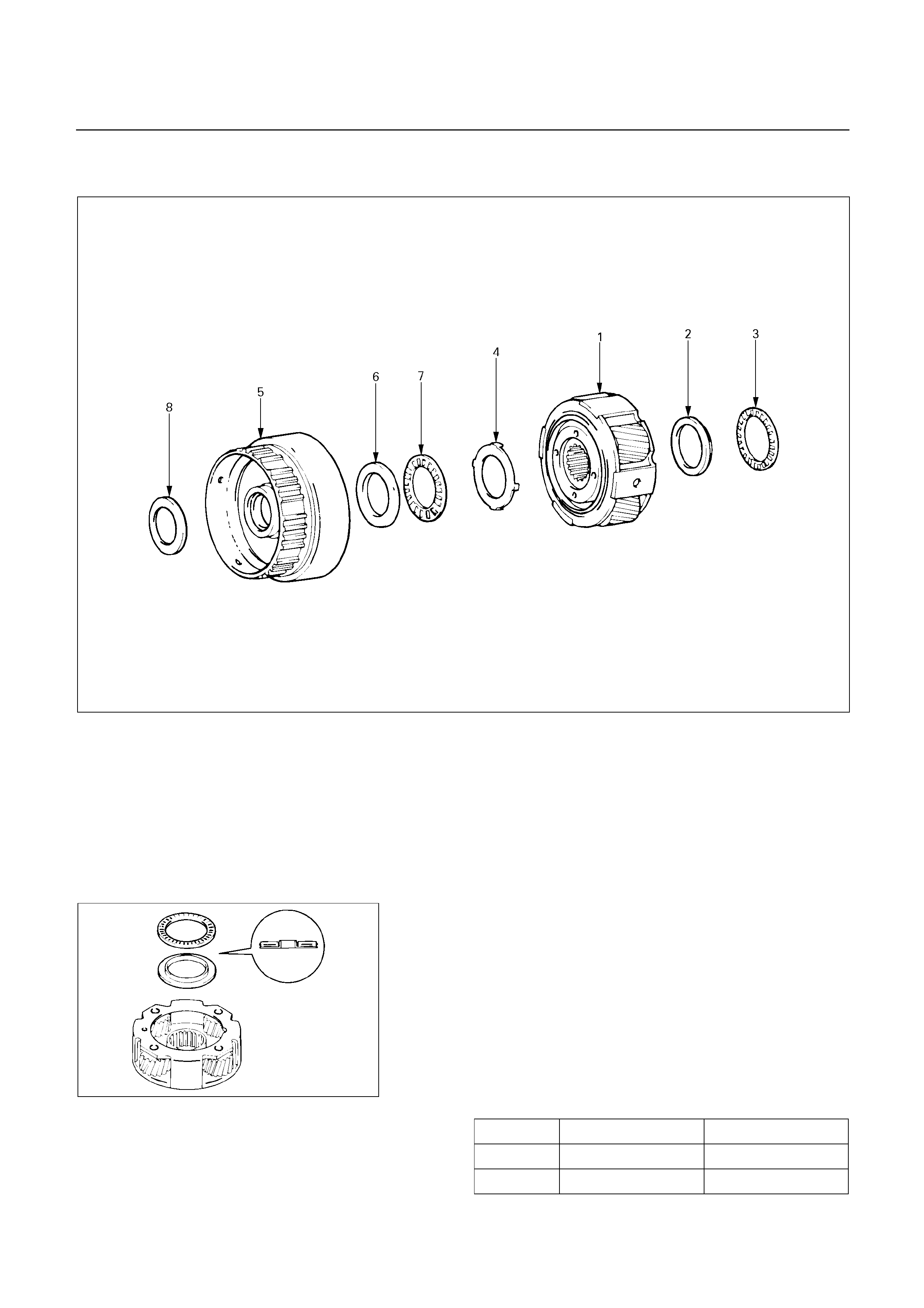
REASSEMBLY
247R200004
Reassembly steps
1. Front planetary gear
2. Race
3. Thrust bearing
4. Race (Metal)
5. Front planetary ring gear
6. Race
7. Thrust bearing
8. Race
Reassembly steps
1. Front planetary gear
2. Race
3. Thrust bearing
Coat the race and bearing with petroleum jelly.
Install the race and bearing to the rear side of the front
planetary gear.
Bearing and race diameter (Reference)
Inside Outside
Bearing 35.6 mm (1.402 in) 47.7 mm (1.878 in)
247RY00023
Race 33.7 mm (1.327 in) 47.6 mm (1.874 in)
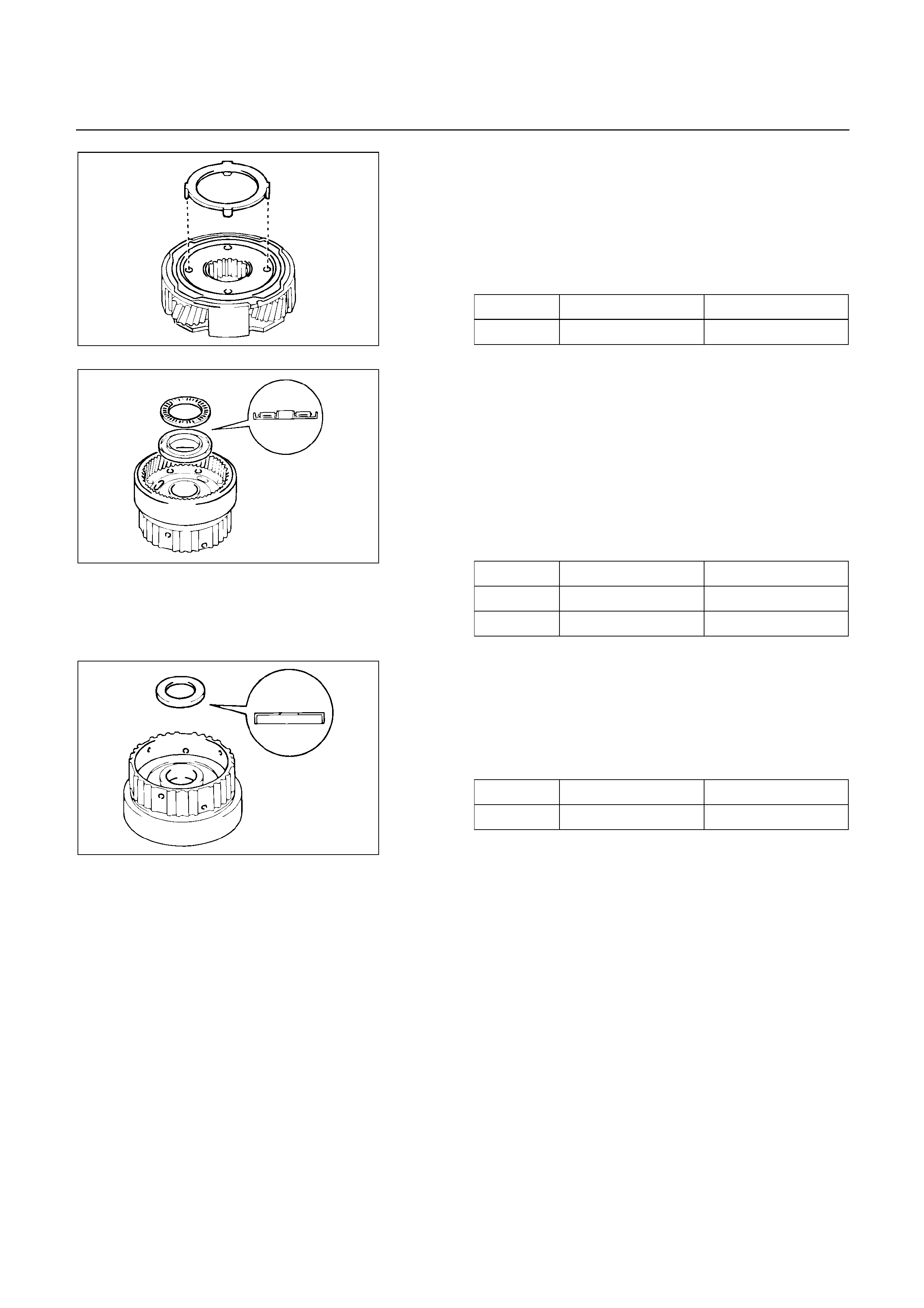
4. Race (Metal)
Turn over the planetary gear and install the race.
Make sure that the lugs fit into the holes on the front
planetary gear.
Race diameter (Reference)
Inside Outside
Race 34.3 mm (1.350 in) 47.8 mm (1.882 in)
247RY00024
5. Front planetary ring gear
6. Race
7. Thrust bearing
Coat the race and bearing with petroleum jelly.
Install the race and bearing onto the rear side of the
front planetary ring gear.
Race and bearing diameter (Reference)
Inside Outside
Race 30.6 mm (1.205 in) 53.6 mm (2.110 in)
Bearing 32.7 mm (1.287 in) 47.7 mm (1.878 in)
247RY00025
8. Race
Turn over the planetary ring gear and install the race
onto the front side of the front planetary ring gear.
Race diameter (Reference)
Inside Outside
Race 26.8 mm (1.055 in) 47.0 mm (1.850 in)
247RY00026
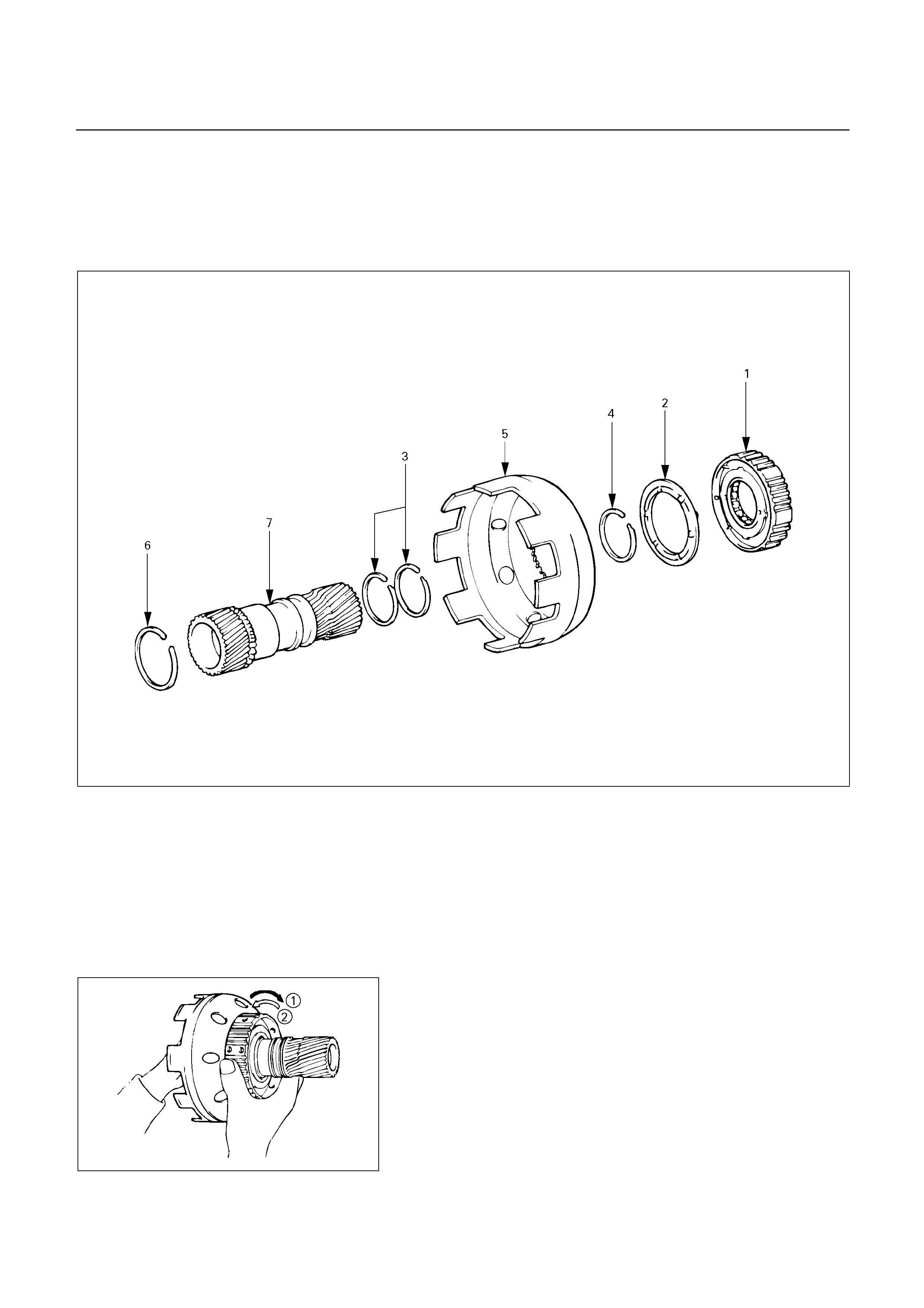
PLANETARY SUN GEAR AND NO.1
ONE-WAY CLUTCH
DISASSEMBLY
248R200005
Disassembly steps
1. One-way clutch and second brake hub
2. Thrust washer (plastic)
3. Oil seal ring (Metal)
4. Snap ring
5. Sun gear input drum
6. Snap ring
7. Planetary sun gear
248RY00051
Disassembly steps
Check operation of No.1 one-way clutch
Hold the planetary sun gear and turn the second brake
hub.
The second brake hub should turn freely clockwise and
should lock counterclockwise.
: Free
: Lock
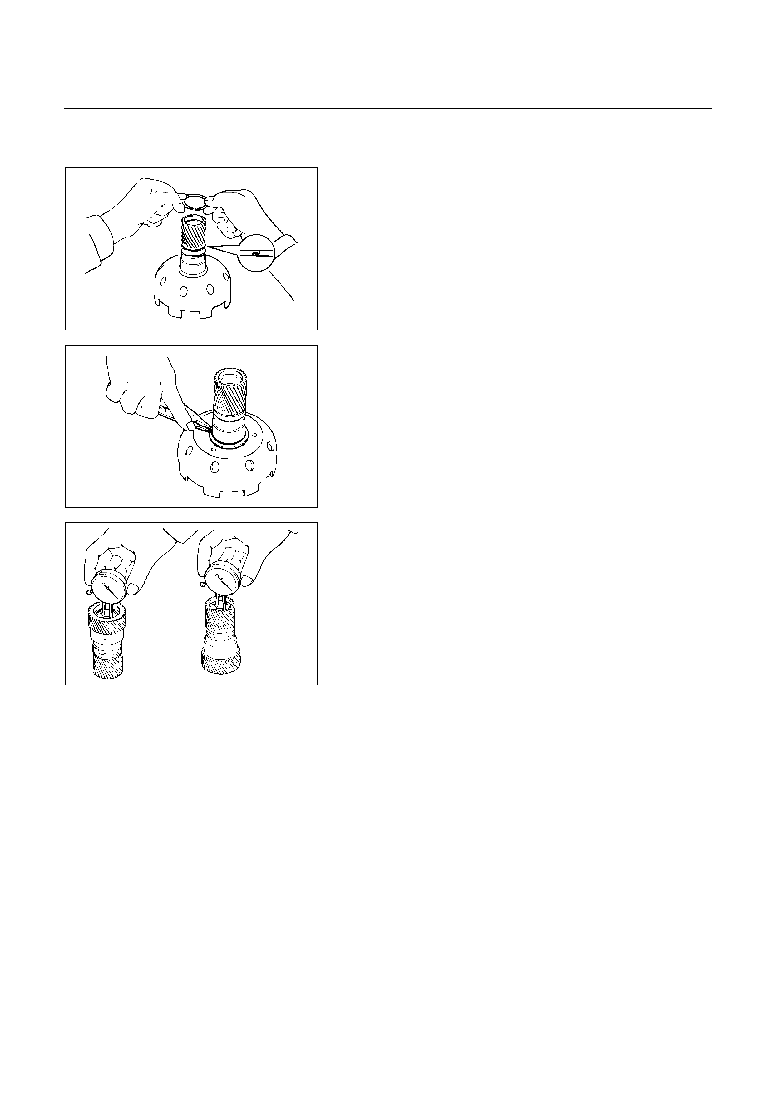
1. One-way clutch and second brake hub
2. Thrust washer (plastic)
248RY00052
3. Oil seal ring (Metal)
Remove two oil seal rings.
248RY00053
4. Snap ring
Remove the snap ring with snap ring pliers.
5. Sun gear input drum
6. Snap ring
7. Planetary sun gear
248RY00054
INSPECTION AND REPAIR
Check planetary sun gear bushing
Using a dial indicator, measure the inside diameter o
f
the planetary sun gear bushing.
Maximum inside diameter: 27.08 mm (1.0661 in)
If the inside diameter is greater than the maximum,
replace the planetary sun gear.
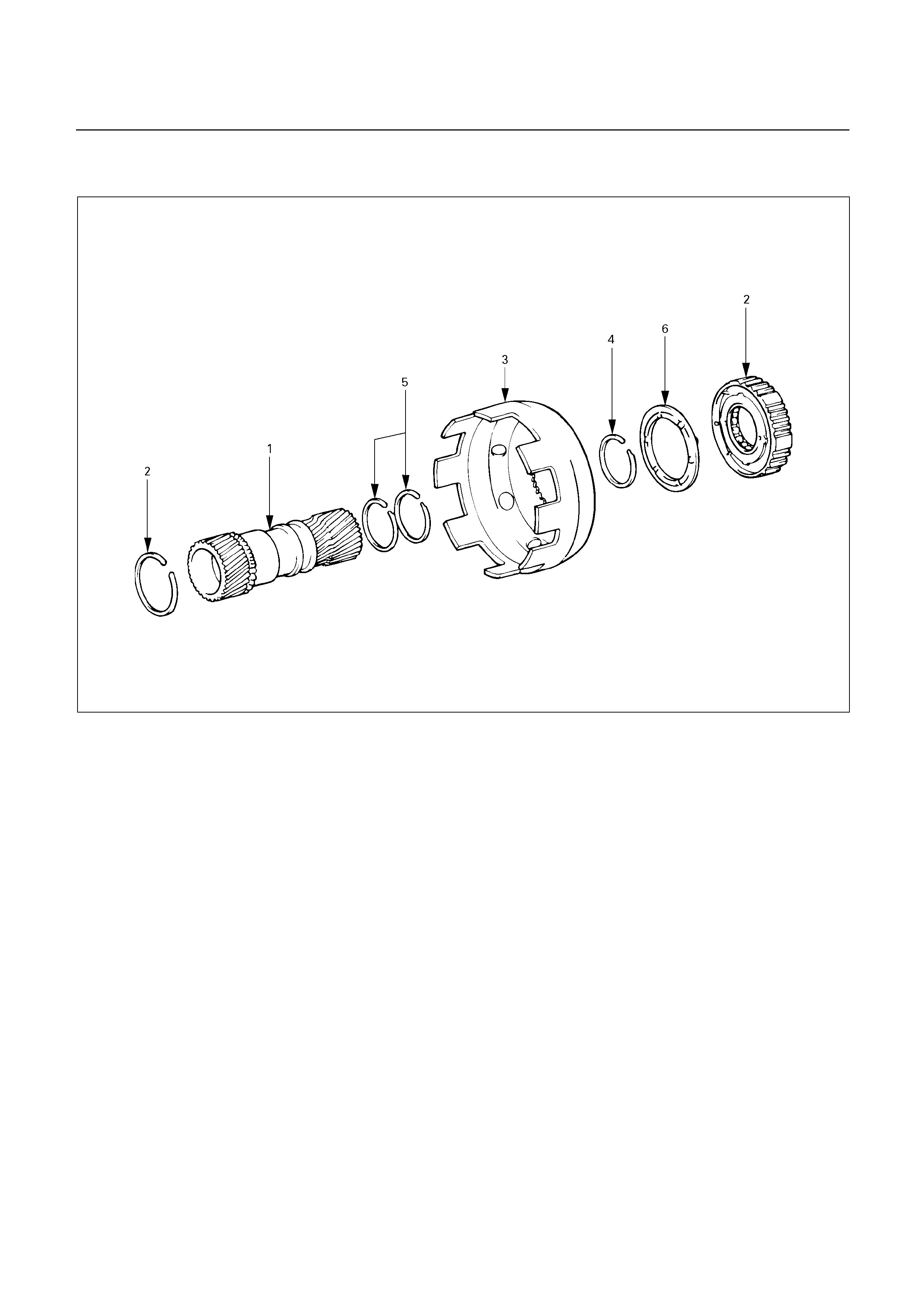
REASSEMBLY
248R200006
Reassembly steps
1. Planetary sun gear
2. Snap ring
3. Sun gear input drum
4. Snap ring
5. Oil seal ring (Metal)
6. Thrust washer (Plastic)
7. One-way clutch and second brake hub
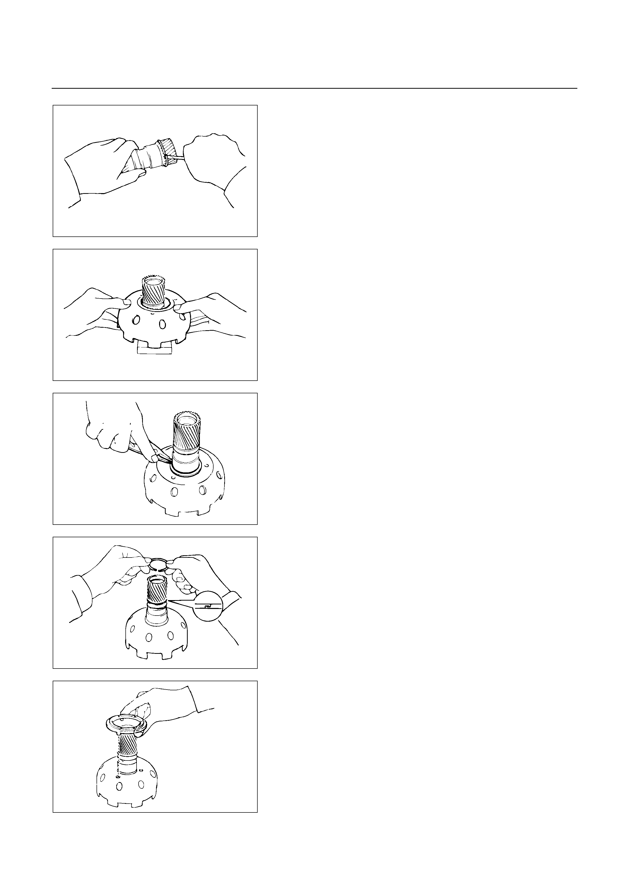
248RY00055
Reassembly steps
1. Planetary sun gear
2. Snap ring
Install snap ring to planetary sun gear.
248RY0056
3. Sun gear input drum
Place a wooden block, etc. as a work stand and place
the planetary sun gear onto it.
Install the sun gear input drum onto the planetary sun
gear.
248RY00053
4. Snap ring
Install snap ring with snap ring pliers.
248RY00052
5. Oil seal ring (Metal)
Coat the two oil seal rings with ATF.
Install the two oil seal rings onto the planetary sun gear.
NOTE:
Do not spread the ring ends too much.
248RY00057
6. Thrust washer (Plastic)
Install thrust washer.
NOTE:
Make sure that the lugs fit into the holes on the sun
gear input drum.
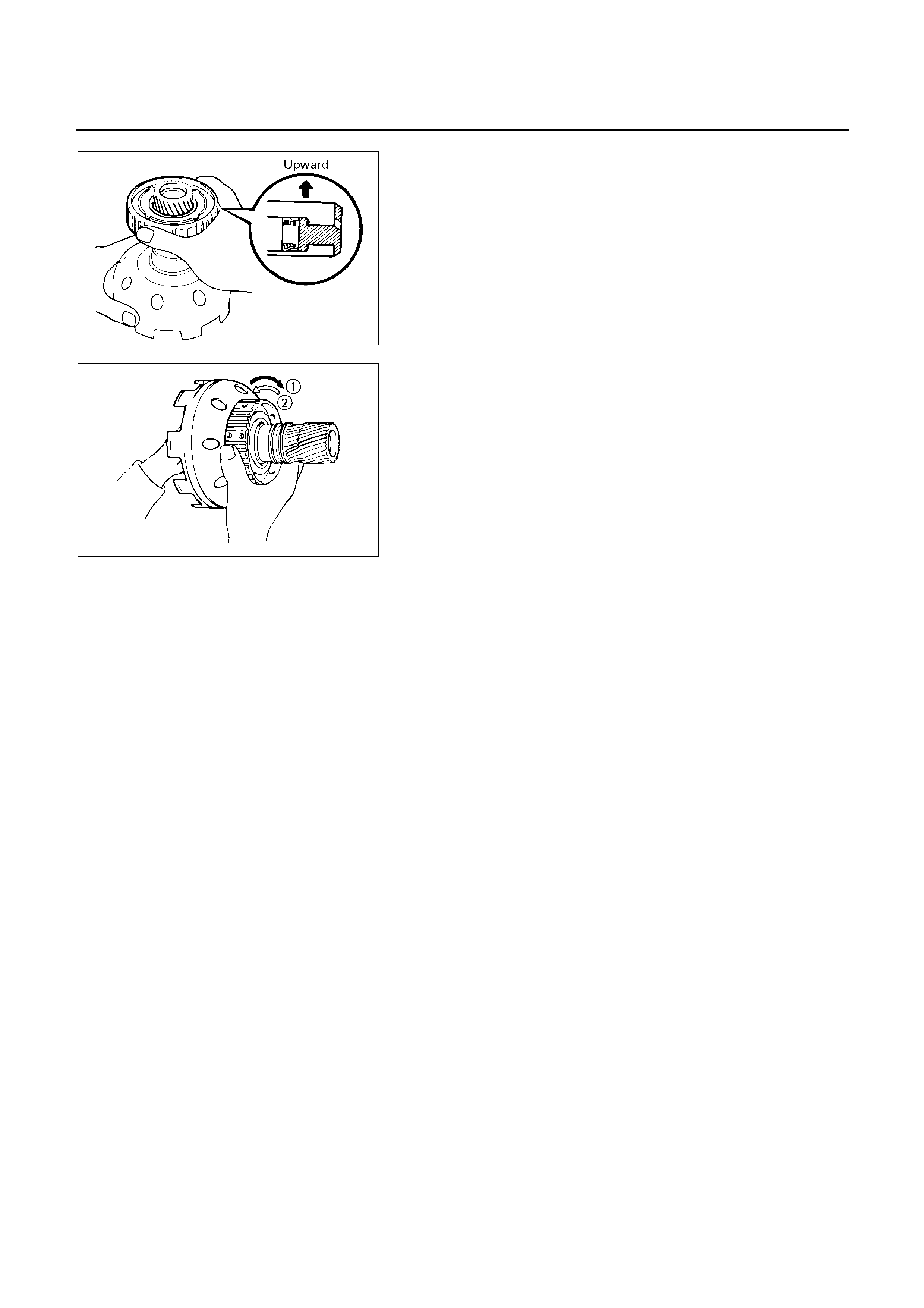
248RY00058
7. One-way clutch and second brake hub
Install assembled No.1 one-way clutch and second
brake hub onto planetary sun gear as shown.
248RY00051
Check operation of No.1 one-way clutch
Hold the planetary sun gear and turn the second brake
hub.
The second brake hub should turn freely clockwise and
should lock counterclockwise.
: Free
: Lock
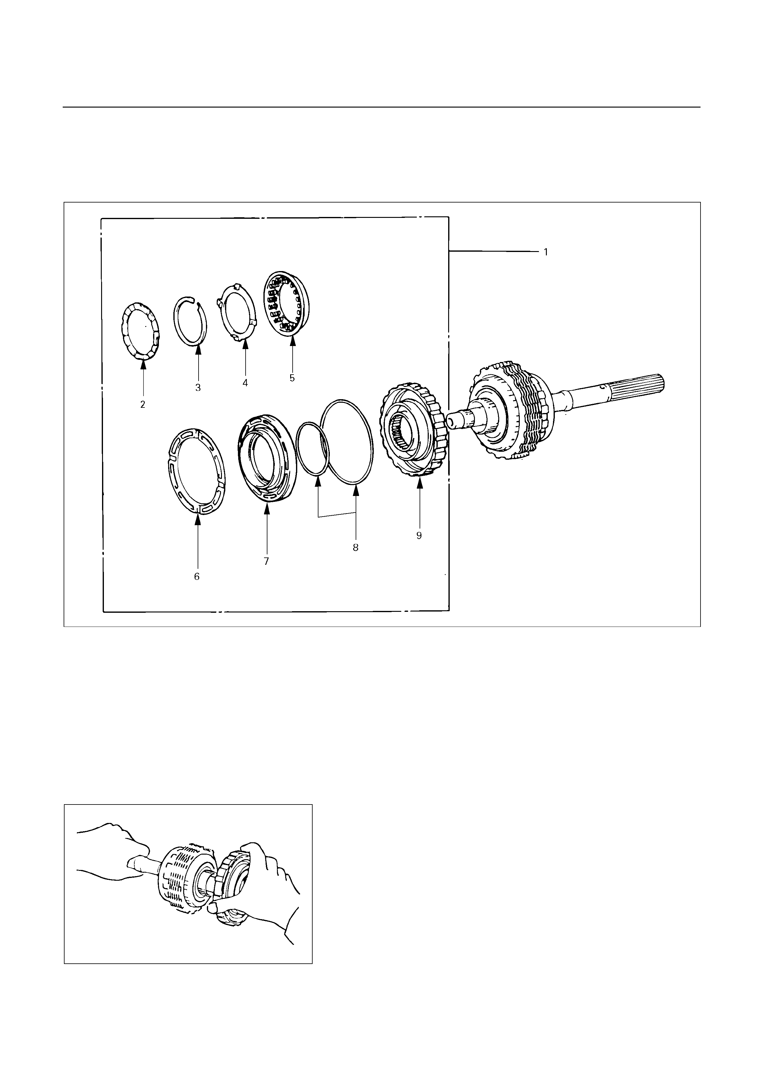
SECOND BRAKE ASSEMBLY (B-2)
DISASSEMBLY
246R200001
Disassembly steps
1. Second brake assembly
2. Thrust washer (Plastic)
3. Snap ring
4. Spring retainer
5. Piston return spring
6. Piston sleeve
7. Second brake piston
8. O-ring
9. Second brake drum
246RY00007
Disassembly steps
1. Second brake assembly
Remove second brake assembly from output shaft.
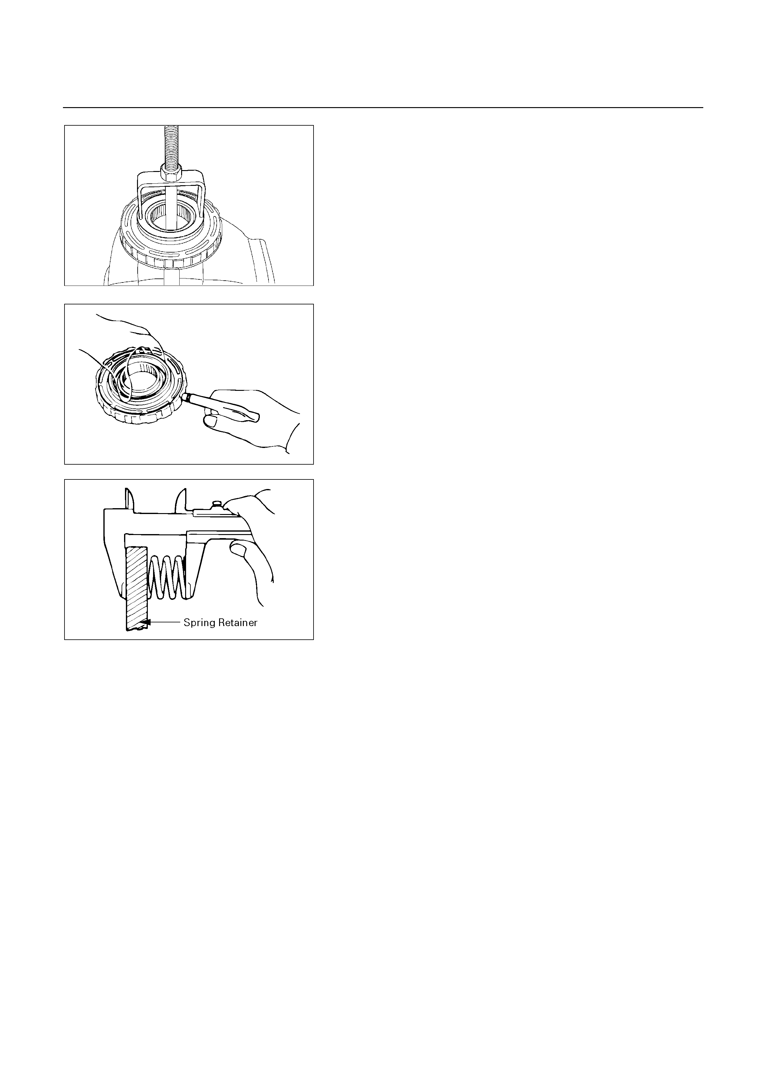
247RY00001
2. Thrust washer (Plastic)
3. Snap ring
Place special tool on the spring retainer, and compress
the return spring.
Spring compressor: 5-8840-0254-0 (J-25048)
Remove the snap ring with snap ring pliers.
4. Spring retainer
5. Piston return spring
6. Piston sleeve
246RY00008
7. Second brake piston
Holding the second brake piston by hand, appl
y
compressed air to the second brake drum to remove
the second brake piston.
Remove the second brake piston.
8. O-ring
9. Second brake drum
247RY00034
INSPECTION AND REPAIR
Check piston return spring
Using calipers, measure the free length of the return
spring.
Standard length: 16.05 mm (0.6319 in)
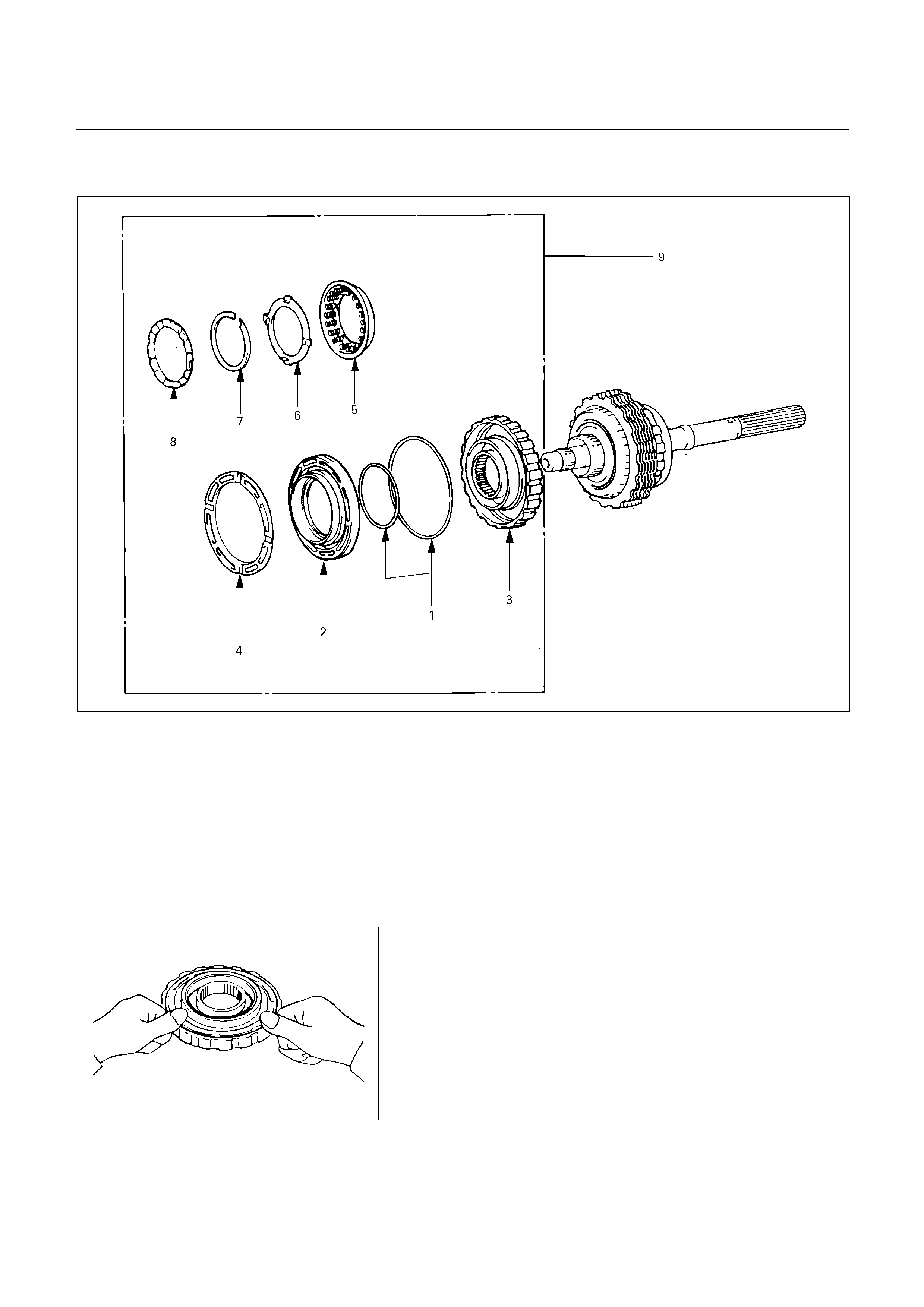
REASSEMBLY
246R200002
Reassembly steps
1. O-ring
2. Second brake piston
3. Second brake drum
4. Piston sleeve
5. Piston return spring
6. Spring retainer
7. Snap ring
8. Thrust washer (Plastic)
9. Second brake assembly
246RY00009
Reassembly steps
1. O-ring
Coat new O-rings with ATF and install them on the
second brake piston.
2. Second brake piston
3. Second brake drum
Being careful not to damage the O-rings, press in the
second brake piston into the second brake drum.
4. Piston sleeve
Install piston sleeve.
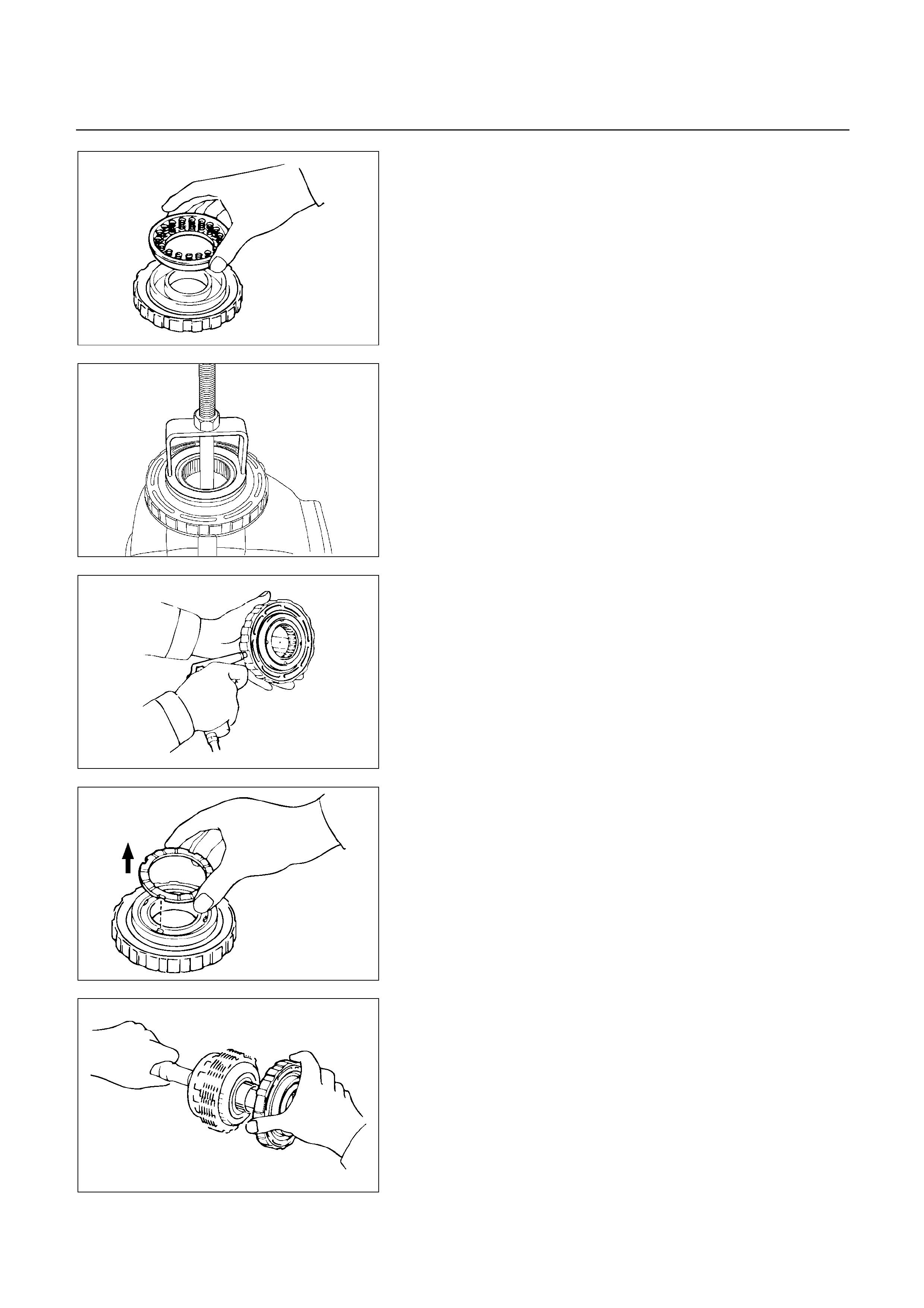
246RY00010
5. Piston return spring
Install piston return spring.
6. Spring retainer
Install spring retainer.
247RY00001
7. Snap ring
Place special tool on the spring retainer, and compress
the return spring.
Spring compressor: 5-8840-0254-0 (J-25048)
Install the snap ring with snap ring pliers.
Be sure the end gap of the snap ring is not aligned with
the spring retainer claw.
246RY00011
Check second brake piston movement
Make sure the second brake piston moves smoothl
y
when applying and releasing the low compressed air to
the second brake drum.
246RY00012
8. Thrust washer (plastic)
Coat the thrust washer with petroleum jelly and install it
to the second brake piston, with the grooved side facing
upward.
NOTE:
Make sure that the cutout portions of the thrust
washer match the teeth of the spring retainer.
246RY00014
9. Second brake assembly
Install second brake assembly to output shaft.
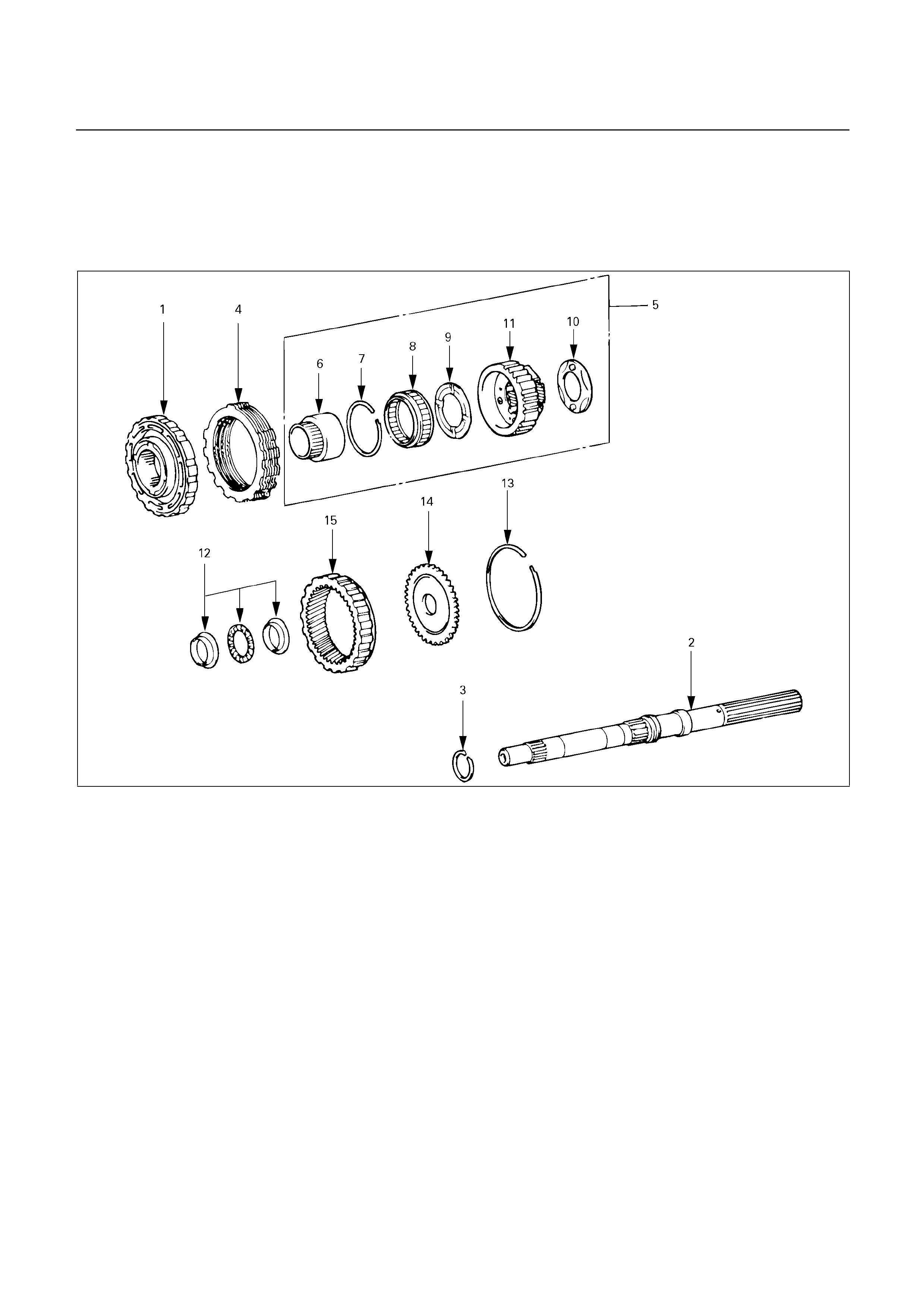
REAR PLANETARY GEAR
ASSEMBLY AND OUTPUT SHAFT
DISASSEMBLY
247R200005
Disassembly steps
1. Second brake assembly
2. Output shaft
3. Oil seal ring
4. Disc, plate and flange (B-3)
Seven discs and seven plates (UBS)
Six discs and six plates (TFR/S)
5. Rear planetary gear assembly
6. One-way clutch inner race
7. Snap ring
8. One-way clutch
9. Thrust washer (Plastic)
10. Thrust washer (Plastic)
11. Rear planetary gear
12. Thrust bearing and race
13. Snap ring
14. Ring gear flange
15. Rear planetary ring gear
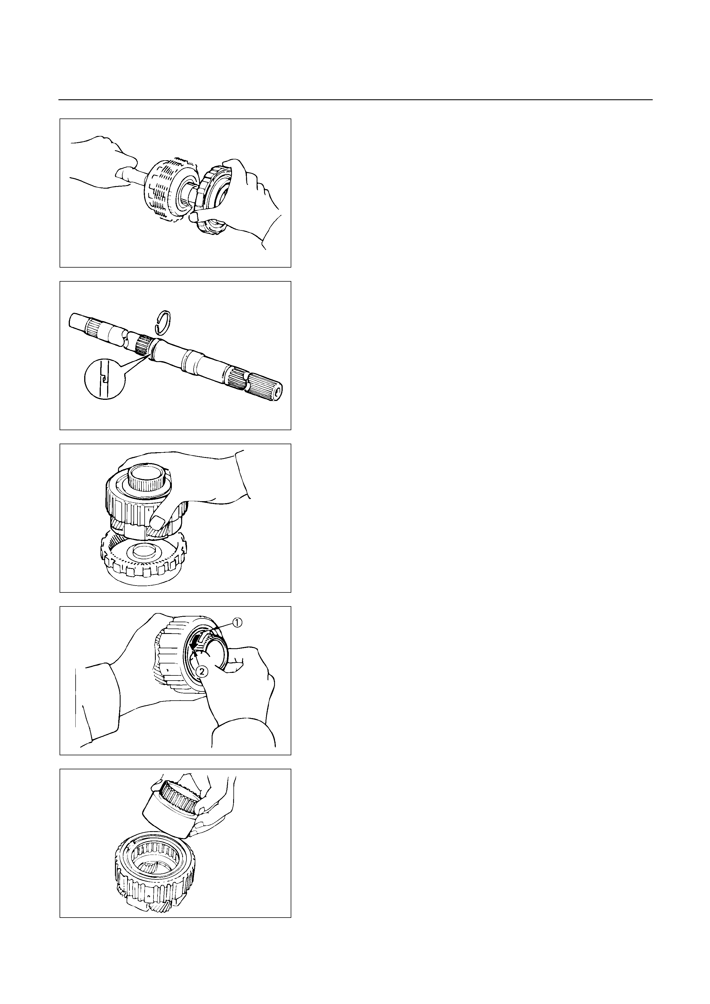
246RY00014
Disassembly steps
1. Second brake assembly
2. Output shaft
Remove second brake assembly from output shaft.
247RY00028
3. Oil seal ring
Remove oil seal ring from output shaft.
4. Disc, plate and flange (B-3)
Seven discs and seven plates (UBS)
Six discs and six plates (TFR/S)
247RY00029
5. Rear planetary gear assembly
Remove rear planetary gear from rear planetary ring
gear.
247RY00030
Check operation of No.2 one-way clutch
Hold the planetary gear and turn the one-way clutch
inner race.
The one-way clutch inner race should turn freel
y
counterclockwise and should lock clockwise.
: Lock
: Free
247RY00031
6. One-way clutch inner race
Remove the one-way clutch inner race from the rea
r
planetary gear.
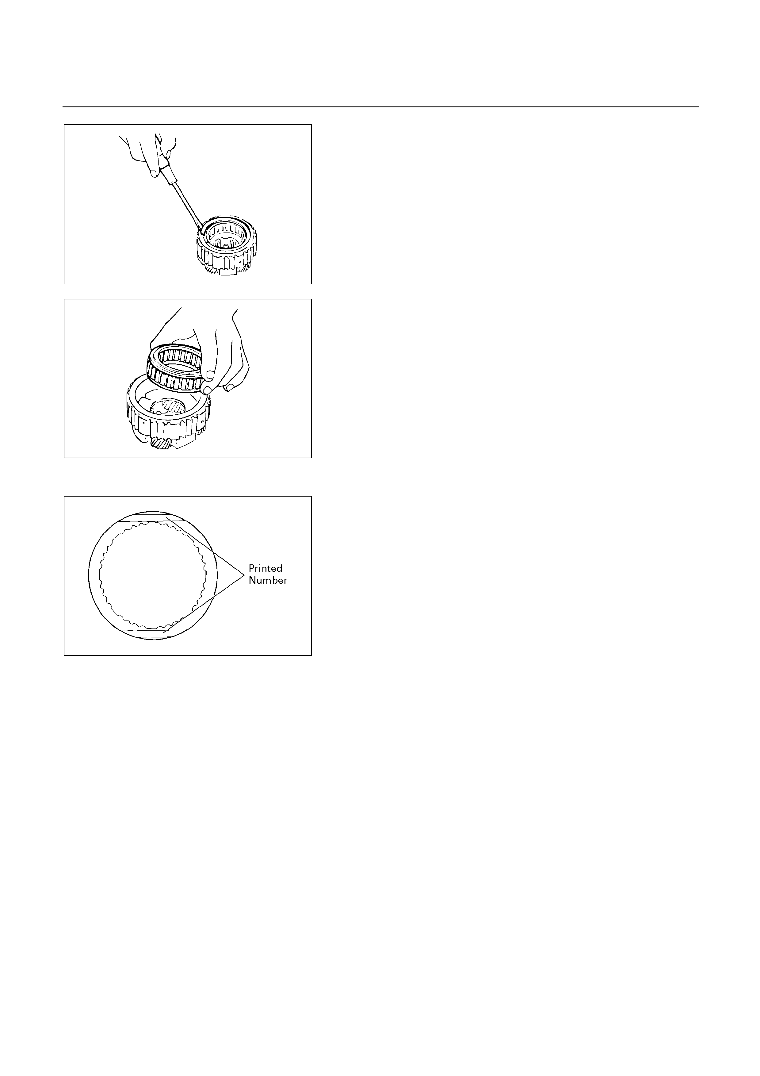
247RY00032
7. Snap ring
Remove the snap ring with a screwdriver.
247RY00033
8. One-way clutch
Remove the one-way clutch with retainers from the
planetary gear.
9. Thrust washer (Plastic)
10. Thrust washer (Plastic)
11. Rear planetary gear
12. Thrust bearing and race
13. Snap ring
14. Ring gear flange
15. Rear planetary ring gear
248RY00045
Check disc, plate and flange
Check to see if the sliding surface of the disc, plate and
flange are worn or burnt. If necessary, replace them.
If the lining of the disc is peeling off or discolored, o
r
even if parts of the printed numbers are defaced,
replace all discs.
Before assembling new discs, soak them in ATF fo
r
at least fifteen minutes.
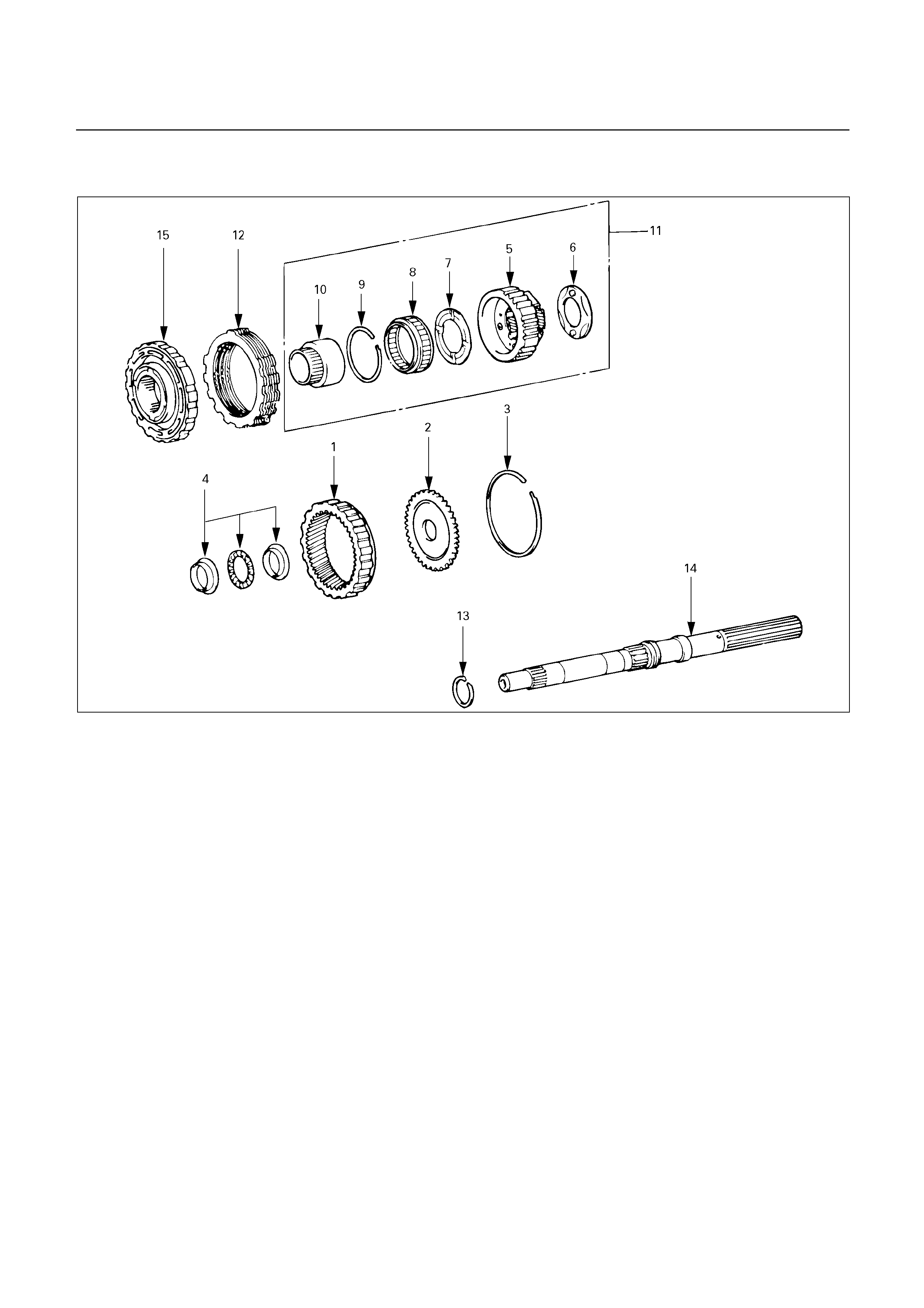
REASSEMBLY
247R200006
Reassembly steps
1. Rear planetary ring gear
2. Ring gear flange
3. Snap ring
4. Thrust bearing and race
5. Rear planetary gear
6. Thrust washer (Plastic)
7. Thrust washer (Plastic)
8. One-way clutch
9. Snap ring
10. One-way clutch inner race
11. Rear planetary gear assembly
12. Disc, plate and flange (B-3)
Seven discs and seven plates (UBS)
Six discs and six plates (TFR/S)
13. Oil seal ring
14. Output shaft
15. Second brake assembly
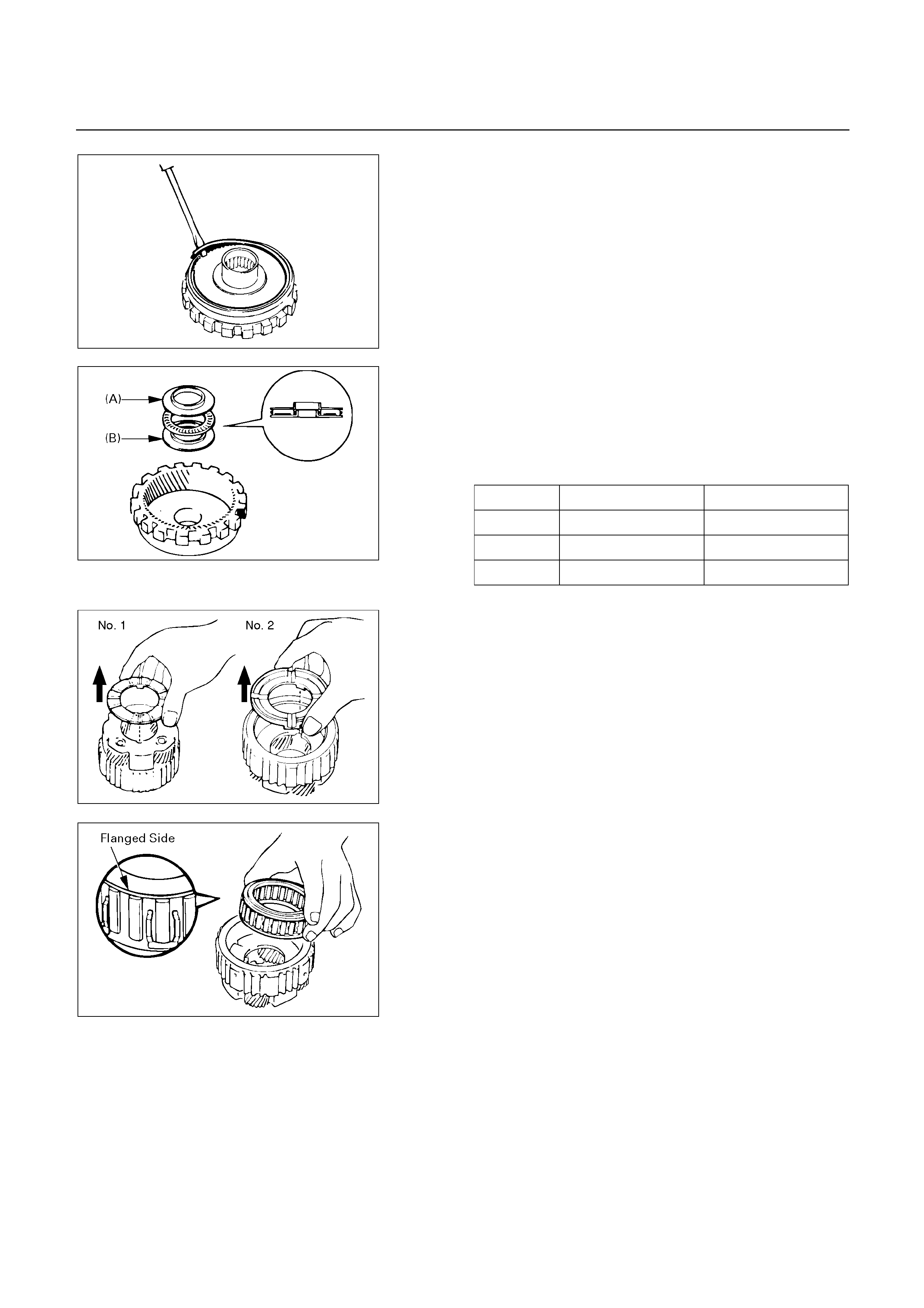
247RY00035
Reassembly steps
1. Rear planetary ring gear
2. Ring gear flange
Install ring gear flange to the rear planetary ring gear.
3. Snap ring
Install snap ring to the rear planetary ring gear.
4. Thrust bearing and race
Coat the races and bearing with petroleum jelly, and
install them onto the rear planetary ring gear.
Races and bearing diameter (Reference)
Inside Outside
Race (A) 28.8 mm (1.134 in) 44.8 mm (1.764 in)
Bearing 30.1 mm (1.185 in) 44.7 mm (1.760 in)
Race (B) 27.8 mm (1.094 in) 44.8 mm (1.764 in)
247RY00036
247RY00037
5. Rear planetary gear
6. Thrust washer (Plastic)
7. Thrust washer (Plastic)
Coat the thrust washers with petroleum jelly.
Install the thrust washers onto both sides of the rea
r
planetary gear, facing the grooved side upward.
NOTE:
Make sure that the lugs fit into the cutout portions
on the rear planetary gear.
247RY00038
8. One-way clutch
Install the one-way clutch with the flanged side facing
upward onto the rear planetary gear.
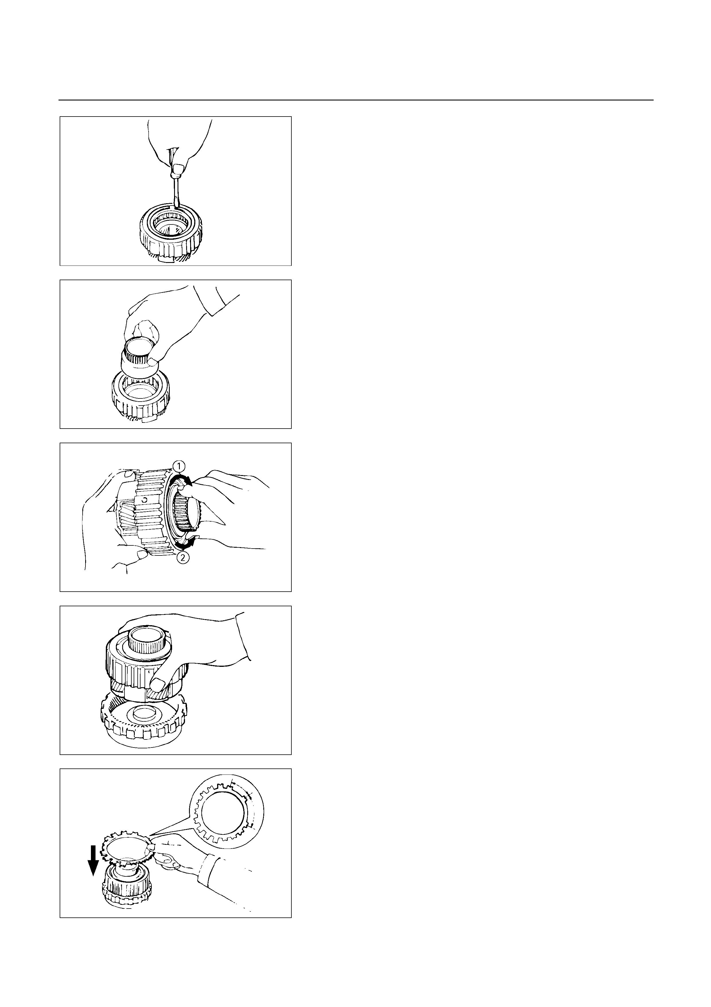
247RY00039
9. Snap ring
Install snap ring.
247RY00040
10. One-way clutch inner race
While turning counterclockwise, install one-way clutch
inner race to rear planetary gear.
247RY00041
Check operation of one-way clutch
Hold the planetary gear and turn the one-way clutch
inner race.
The one-way clutch inner race should turn freel
y
counterclockwise and should lock clockwise.
: Lock
: Free
247RY00029
11. Rear planetary gear assembly
Install rear planetary gear onto rear planetary ring gear.
246RY00013
12. Disc, plate and flange (B-3)
Install a brake flange onto the rear planetary gea
r
assembly.
Install a clutch plate onto the rear planetary gea
r
assembly.
NOTE:
The claw interval of the plate should be as shown in
the figure when viewing the clutch plate from the
arrow direction.
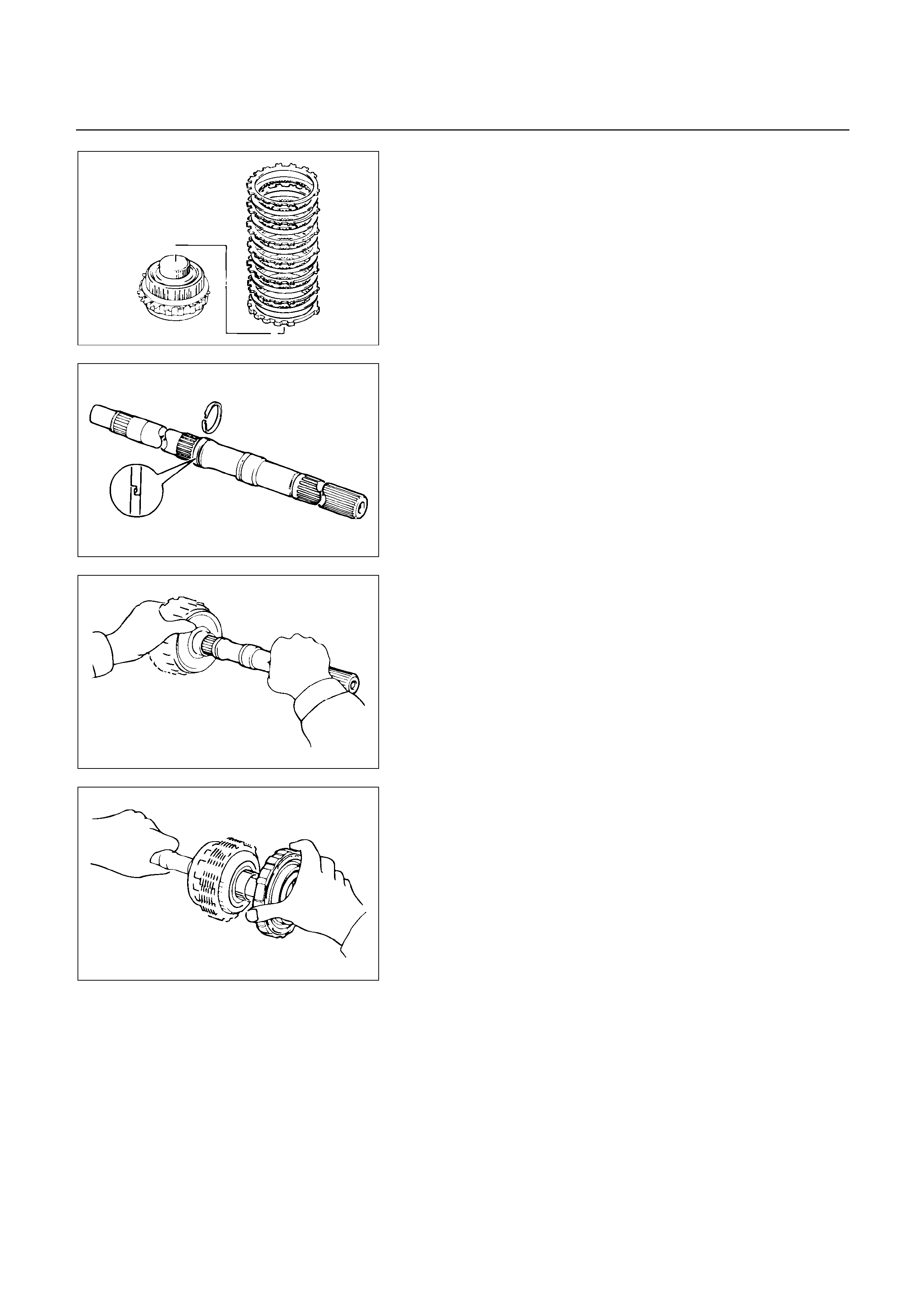
247RY00047
Install seven clutch discs and seven brake plates (UBS)
or six clutch discs and six brake plates (TFR/S)
alternately, starting with clutch disc, onto the rea
r
planetary gear assembly.
247RY00028
13. Oil seal ring
Coat the oil seal ring with ATF and install it to the output
shaft.
NOTE:
Do not spread the ring ends too much.
247RY00042
14. Output shaft
Install output shaft into rear planetary gear assembly.
246RY00014
15. Second brake assembly
Install second brake assembly to output shaft.
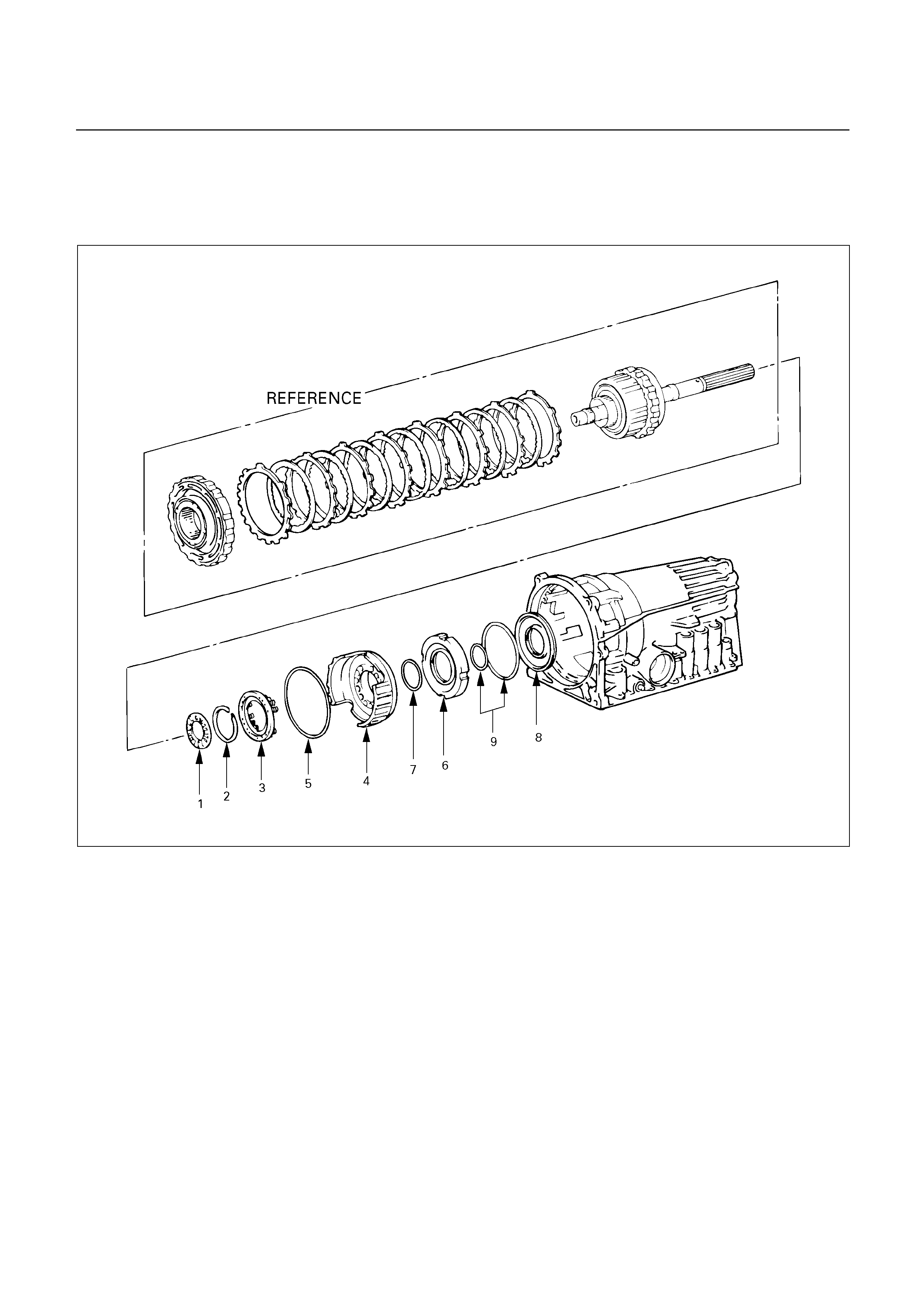
FIRST AND REVERSE BRAKE (B-3)
DISASSEMBLY
246RY00024
Disassembly steps
1. Thrust bearing and race
2. Snap ring
3. Piston return spring
4. First and reverse brake piston No.2
5. O-ring
6. Reaction sleeve
7. O-ring
8. First and reverse brake piston No.1
9. O-ring
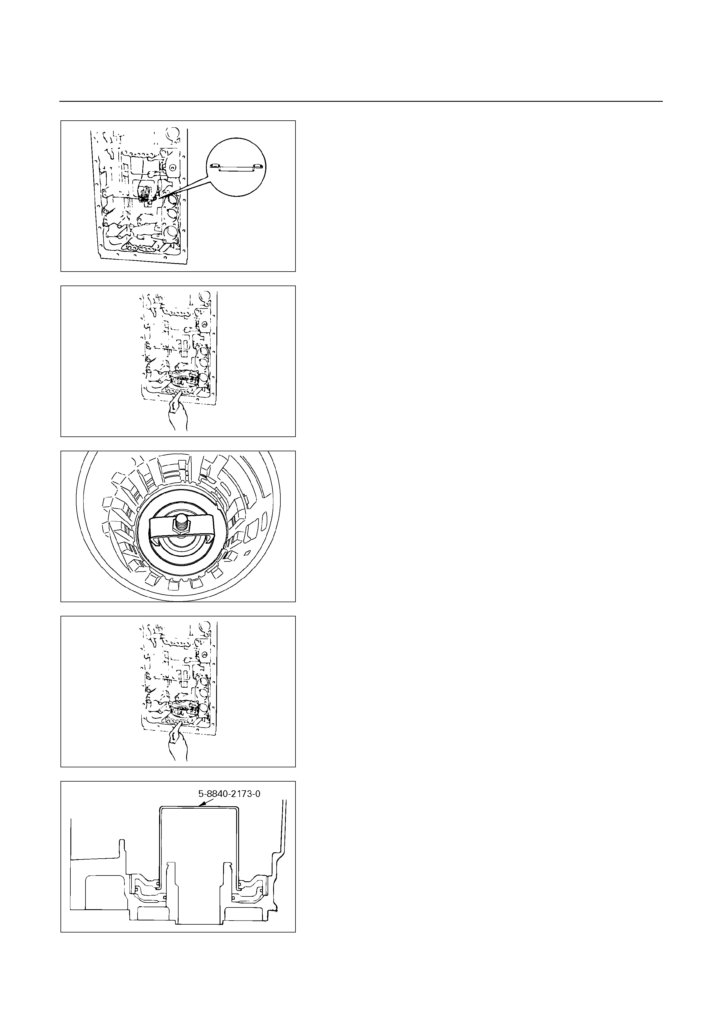
247RY00043
Disassembly steps
1. Thrust bearing and race
Remove assembled bearing and race from
transmission case.
246RY00016
Check first and reverse brake piston movement
Make sure that first and reverse brake piston moves
smoothly when applying and releasing the compressed
air into the transmission case.
247RY00002
2. Snap ring
Set special tool on the spring retainer, and compress
the return spring.
Spring compressor: 5-8840-0254-0 (J-25048)
Remove the snap ring with snap ring pliers.
3. Piston return spring
246RY00016
4. First and reverse brake piston No.2
Holding the first and reverse brake piston No.2 by hand,
apply compressed air to the transmission case to
remove the first and reverse brake piston No.2.
Remove the first and reverse brake piston No.2.
If the piston does not pop out with compressed air, lift
the piston out with needle-nose pliers.
5. O-ring
246RY00017
6. Reaction sleeve
Insert special tool behind the reaction sleeve and
gradually lift it out of the transmission case.
Reaction sleeve puller: 5-8840-2173-0 (J-37236)
7. O-ring
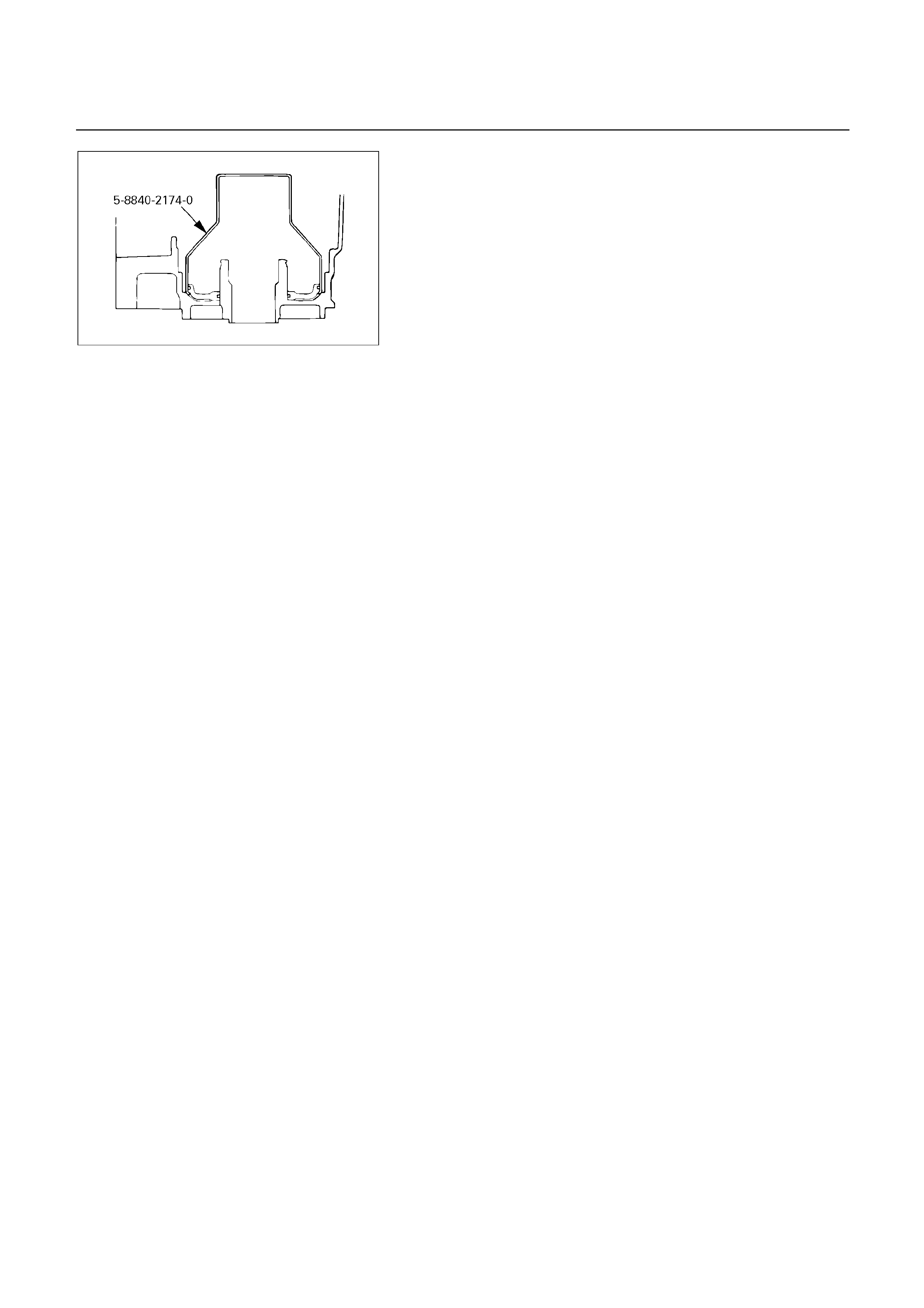
247RY00044
8. First and reverse brake piston No.1
Insert special tool behind the first and reverse brake
piston No.1 and gradually lift it out of the transmission
case.
Piston puller: 5-8840-2174-0 (J-37237)
9. O-ring
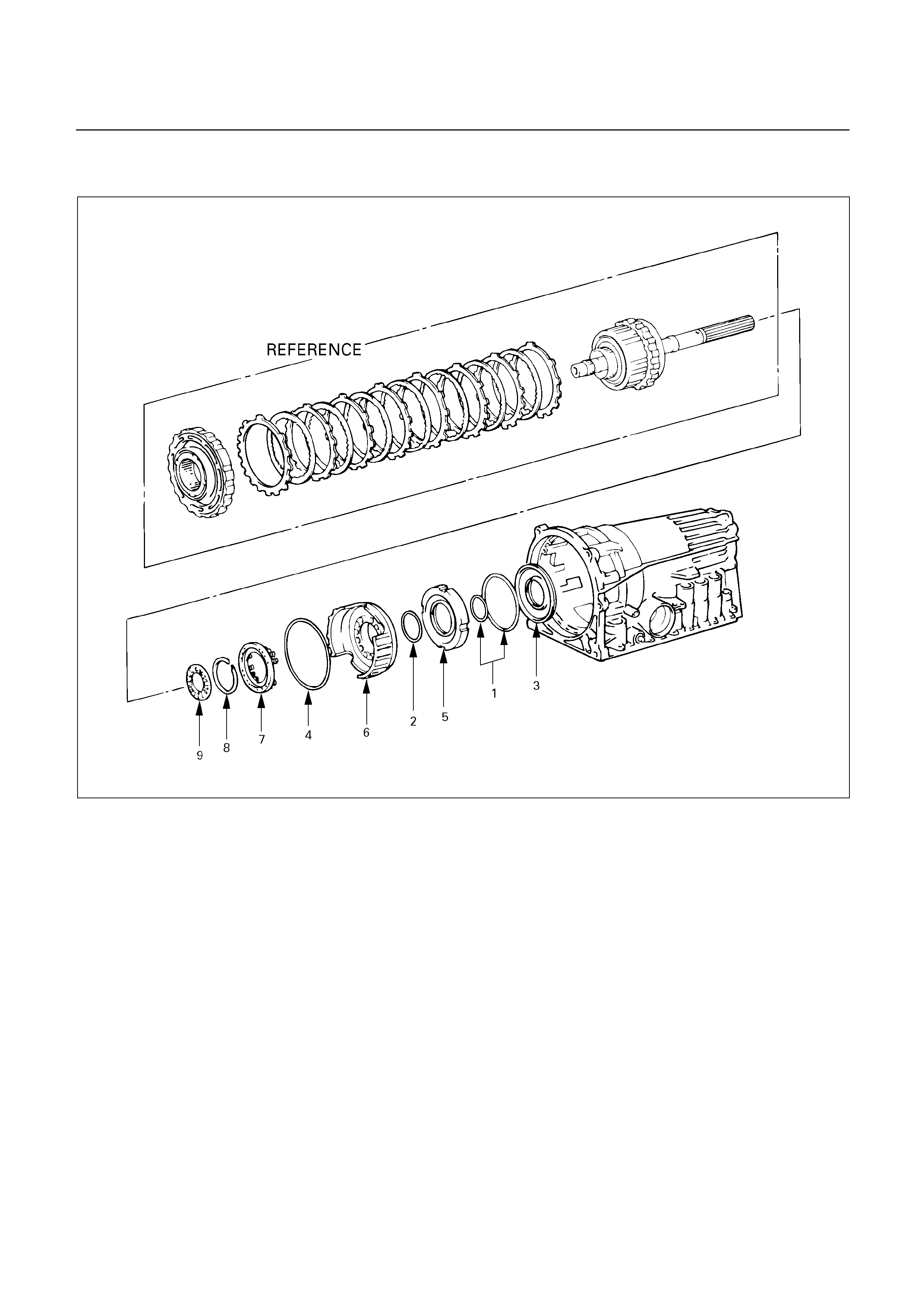
REASSEMBLY
246RY00025
Reassembly steps
1. O-ring
2. O-ring
3. First and reverse brake piston No.1
4. O-ring
5. Reaction sleeve
6. First and reverse brake piston No.2
7. Return spring
8. Snap ring
9. Thrust bearing and race
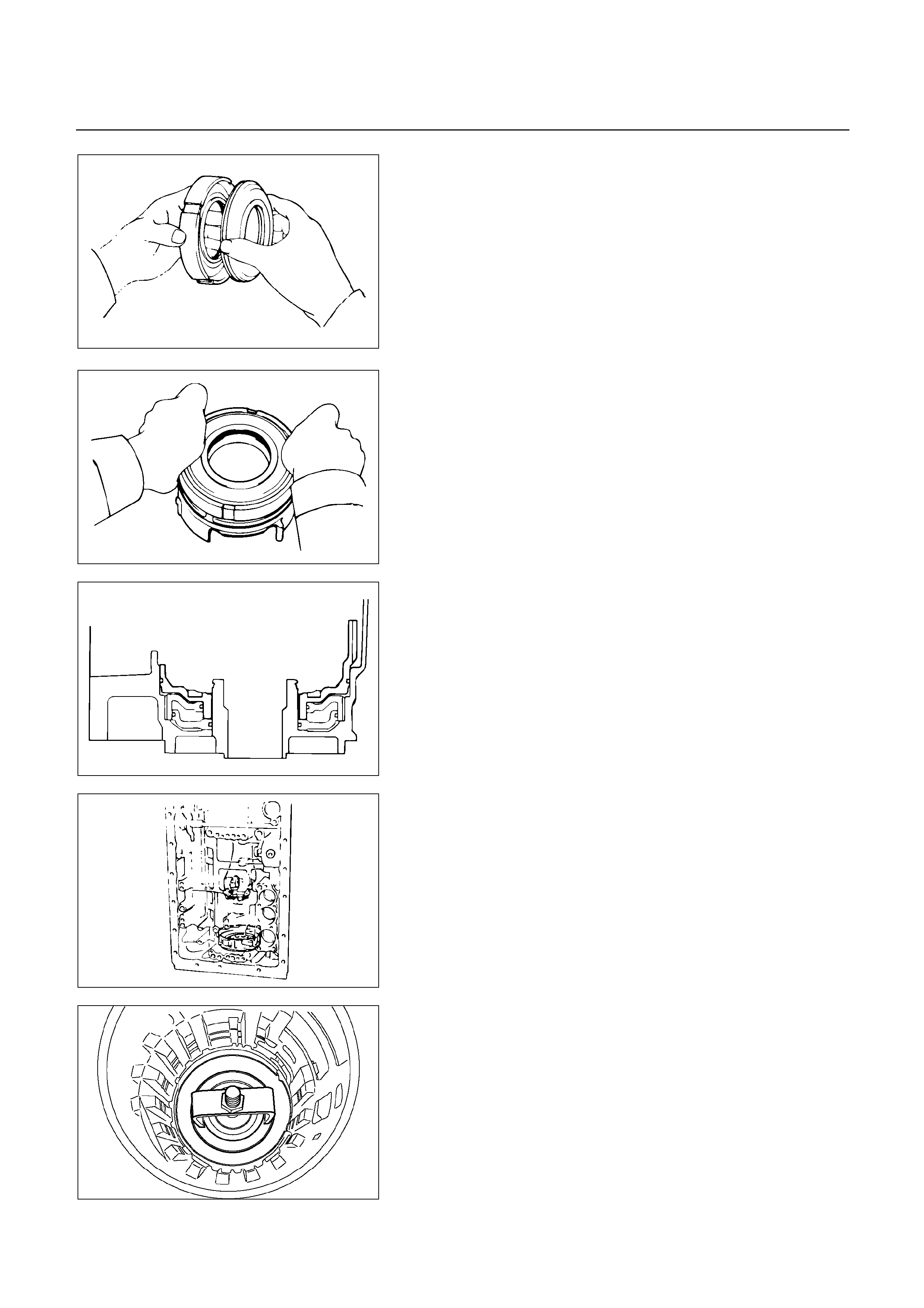
246RY00018
Reassembly steps
1. O-ring
Coat three new O-rings with ATF.
Install the two O-rings on the No.1 piston.
2. O-ring
Install the O-ring on the reaction sleeve.
3. First and reverse brake piston No.1
Install the first and reverse brake piston No.1 to the
reaction sleeve.
246RY00019
4. O-ring
Coat a new O-ring with ATF and install it on the first and
reverse brake piston No.2.
5. Reaction sleeve
Install the first and reverse brake piston No.1 with
reaction sleeve onto the first and reverse brake piston
No.2.
246RY00020
6. First and reverse brake piston No.2
Align the teeth of the first and reverse brake piston No.2
into the proper grooves.
Being careful not to damage the O-rings, press in the
first and reverse brake piston No.2 with No.1 into the
transmission case.
246RY00021
7. Return spring
Place piston return spring onto first and reverse brake
piston No.2.
247RY00002
8. Snap ring
Set special tool as shown, and compress the return
spring with special tool.
Spring compressor: 5-8840-0254-0 (J-25048)
Install the snap ring with snap ring pliers.
Be sure the end gap of the snap ring is not aligned with
the spring retainer claw.
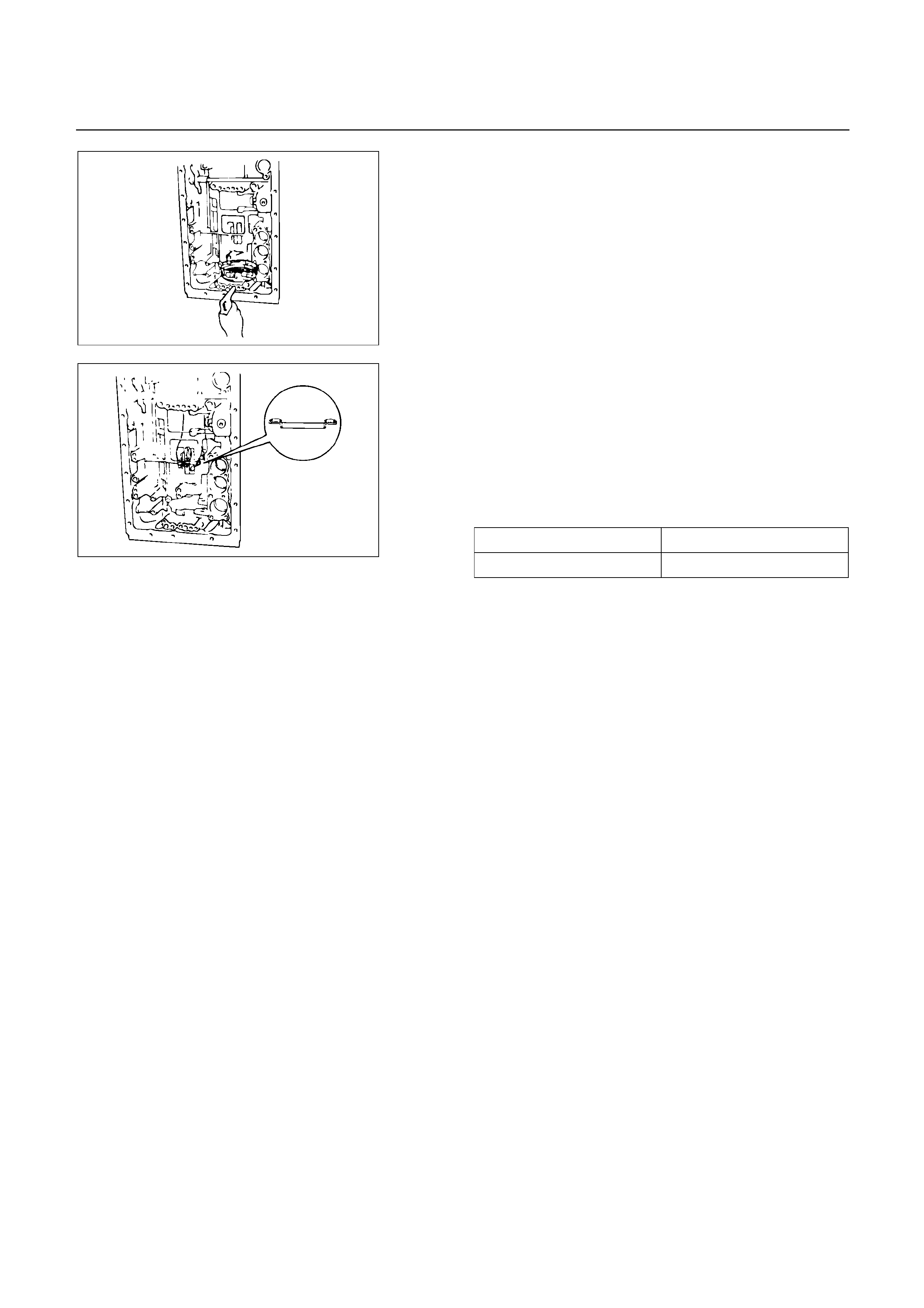
246RY00022
Check first and reverse brake piston movement
Make sure the first and reverse brake piston moves
smoothly when applying and releasing the compressed
air into the transmission case.
9. Thrust bearing and race
Coat the assembled bearing and race with petroleum
jelly.
Install the assembled bearing and race facing the
bearing side upward.
Bearing and race diameter (Reference)
Inside diameter 39.2 mm (1.543 in)
Outside diameter 57.7 mm (2.272 in)
247RY00043
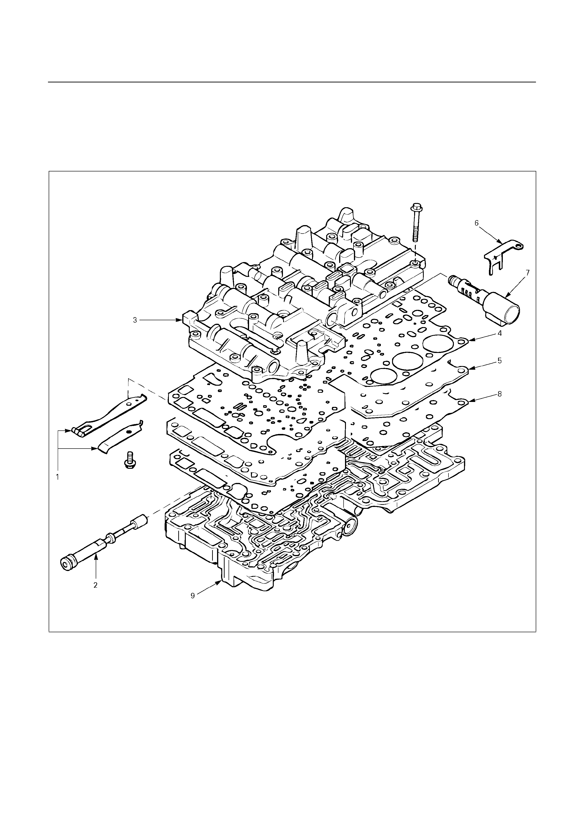
TRANSMISSION VALVE BODY
ASSEMBLY
DISASSEMBLY
240R200039
Disassembly steps
1. Detent spring
2. Manual shift valve
3. Upper valve body
4. No.1 gasket (Upper valve body side)
5. Valve body plate
6. Clamp
7. Pressure control solenoid
8. No.2 gasket (Lower valve body side)
9. Lower valve body
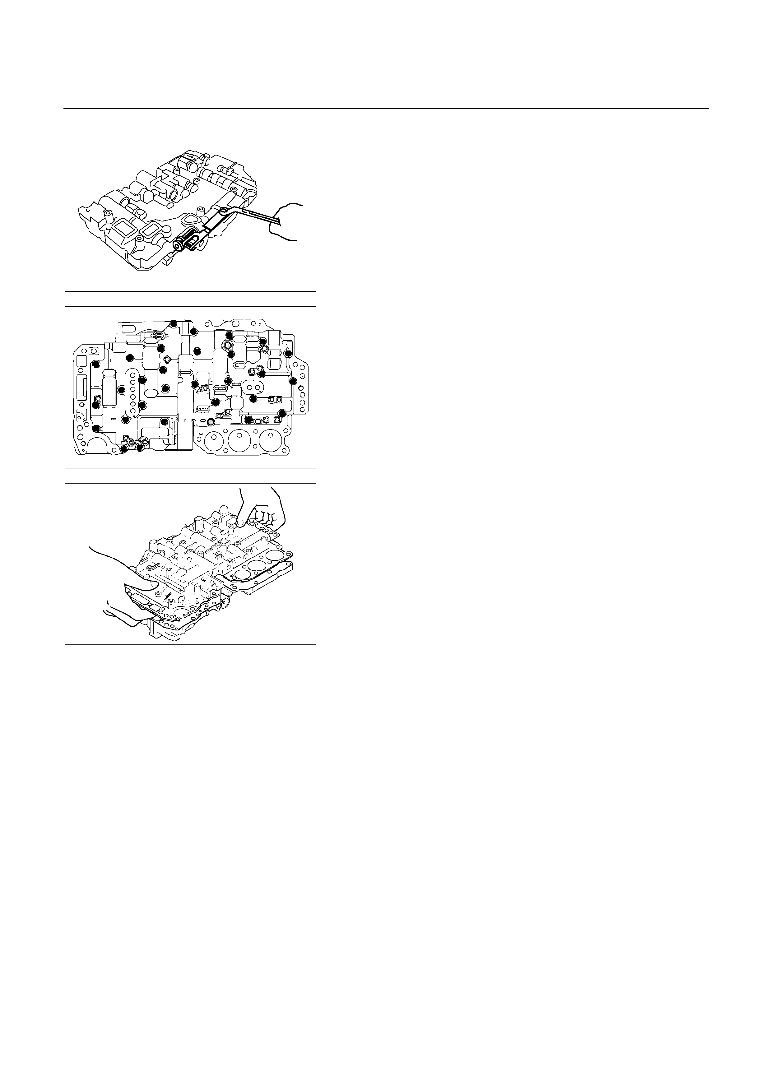
240R200040
Disassembly steps
1. Detent spring
Remove detent spring from valve body.
2. Manual shift valve
Remove manual shift valve.
244R200049
3. Upper valve body
4. No.1 gasket (Upper valve body side)
5. Valve body plate
Turn over assembly and remove thirty bolts.
6. Clamp
7. Pressure control solenoid
244R200061
Hold the valve body plate to the upper valve body.
Lift off upper valve body and plate as a single unit.
NOTE:
Be careful that the check balls and strainers do not
fall out.
8. No.2 gasket (Lower valve body side)
9. Lower valve body
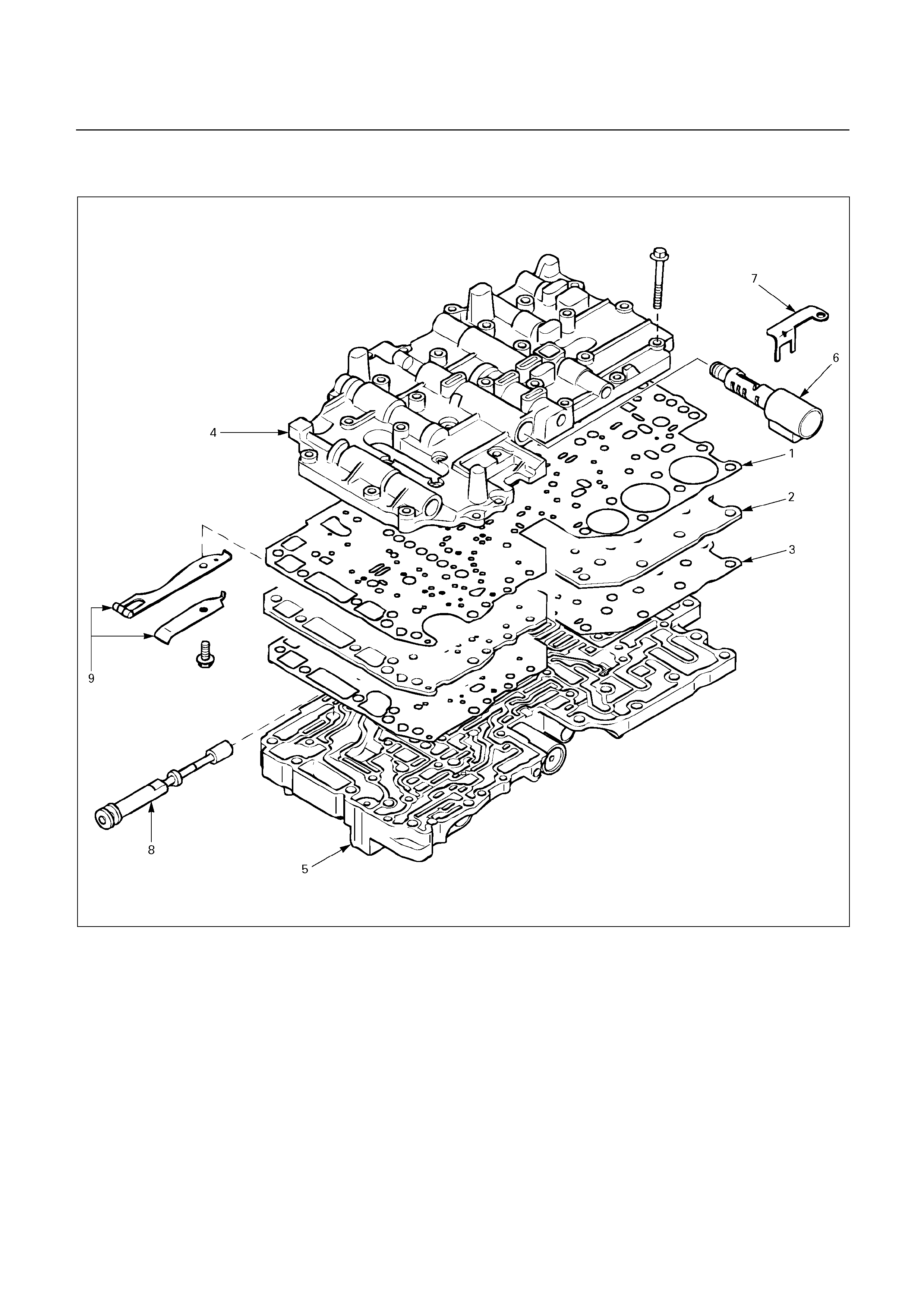
REASSEMBLY
240R200041
Reassembly steps
1. No.1 gasket (Upper valve body side)
2. Valve body plate
3. No.2 gasket (Lower valve body side)
4. Upper valve body
5. Lower valve body
6. Pressure control solenoid
7. Clamp
8. Manual shift valve
9. Detent spring
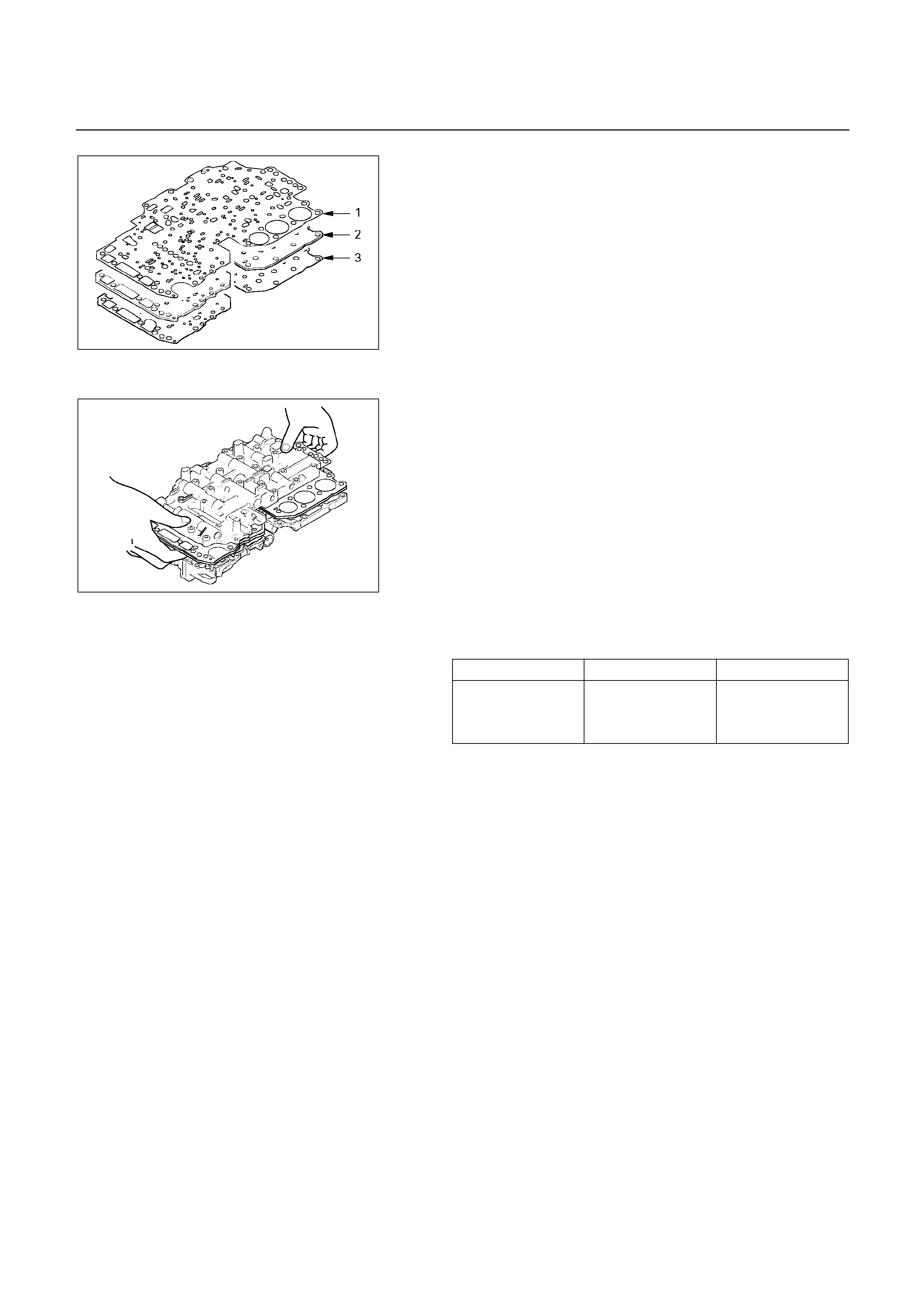
244R200073
Reassembly steps
1. No.1 gasket (Upper valve body side)
Position a new No.1 gasket (1) on upper valve body.
Align the No.1 gasket at each bolt hole.
2. Valve body plate
Position valve body plate (2) on No.1 gasket (1).
Align the plate at each bolt hole.
3. No.2 gasket (Lower valve body side)
Position a new No.2 gasket (3) on valve body plate (2).
Align the No.2 gasket at each bolt hole.
244R200074
4. Upper valve body
5. Lower valve body
Place upper valve body with plate and gaskets on top
lower valve body.
Align each bolt hole and gasket in the valve body.
6. Pressure control solenoid
7. Clamp
Install thirty bolts to upper valve body.
Each bolt is indicated in the figure.
Length (mm) Quantity
A 20 7
B 28 12
C 40 11
Torque: 6.4 N m (0.65 kg m/57 Ib in)
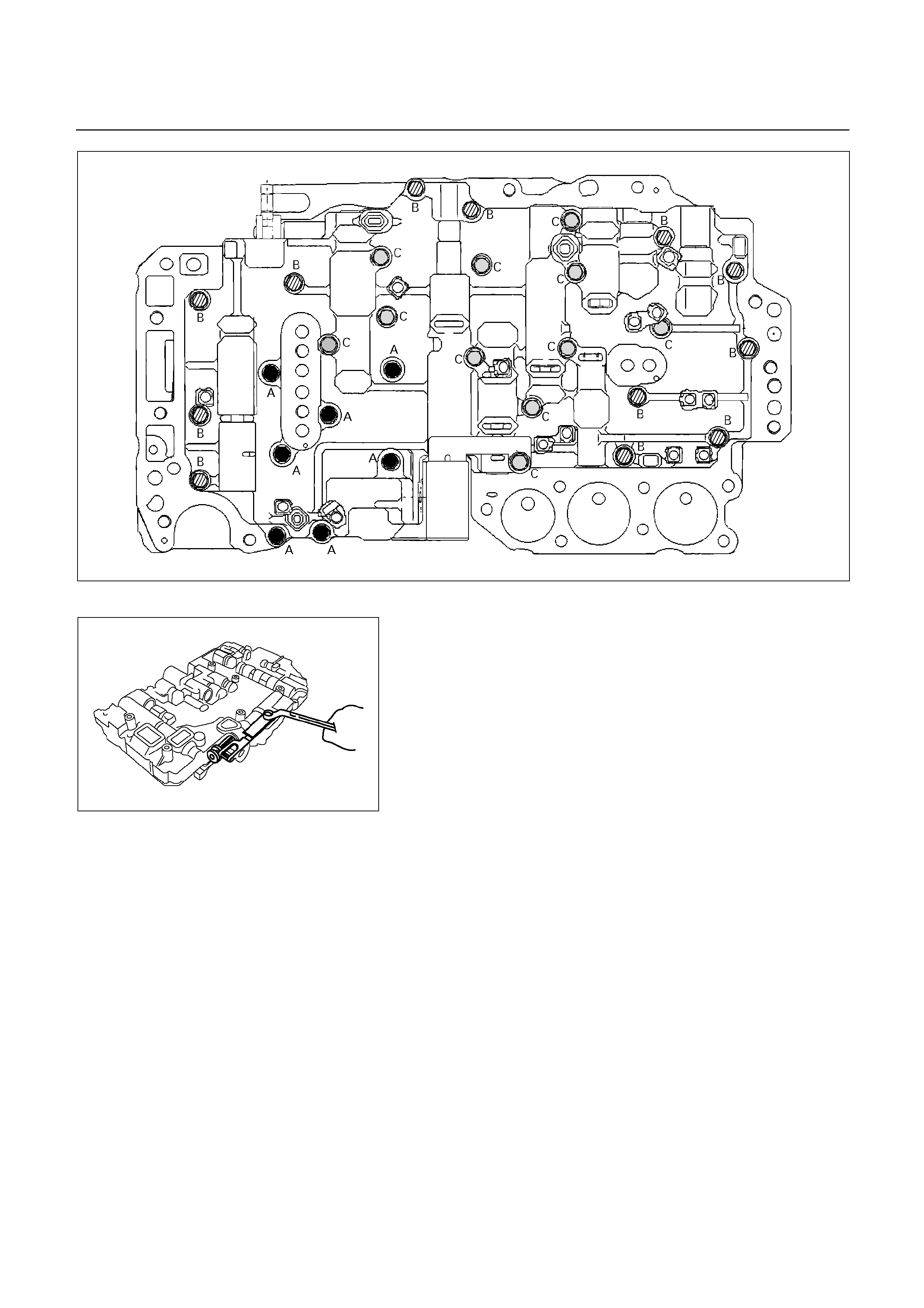
244R200050
240R200040
8. Manual shift valve
Install manual shift valve.
9. Detent spring
Install detent spring.
Torque: 10 N m (1.0 kg m/87 Ib in)
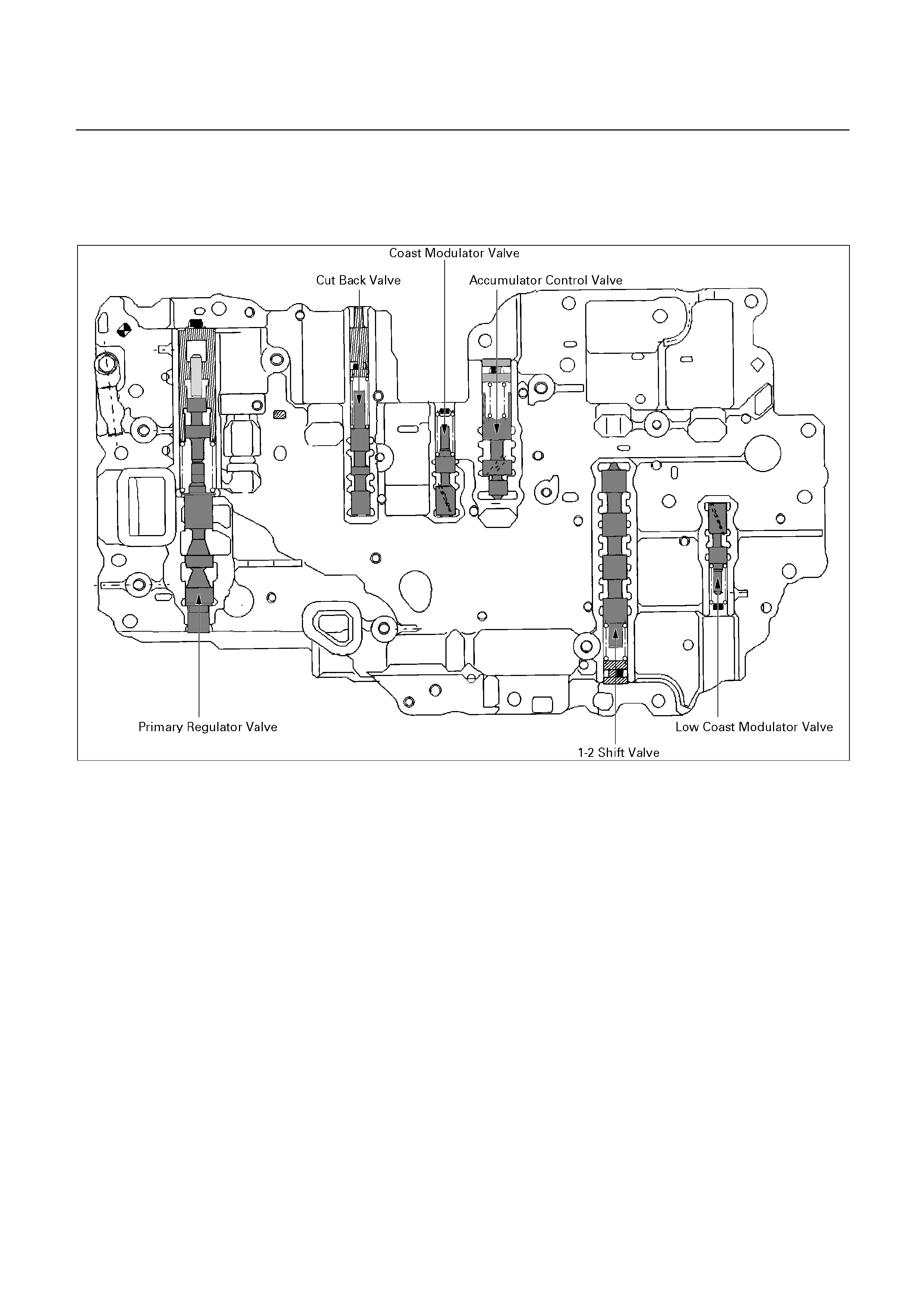
LOWER VALVE BODY
DISASSEMBLY
244R200046
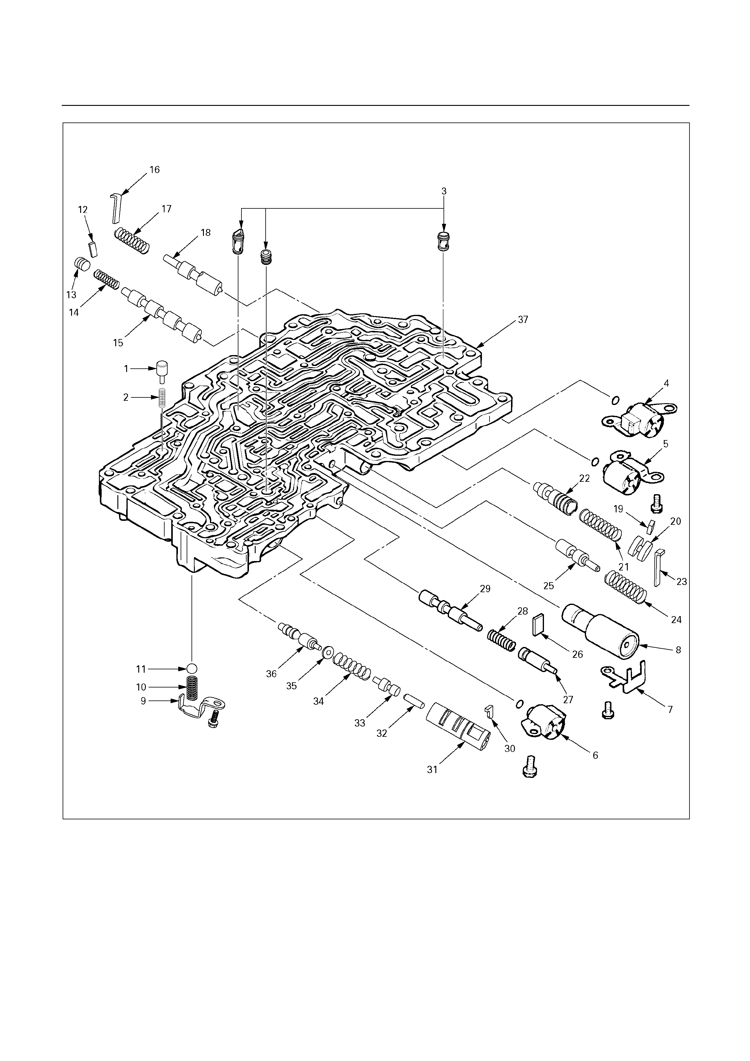
244R200075
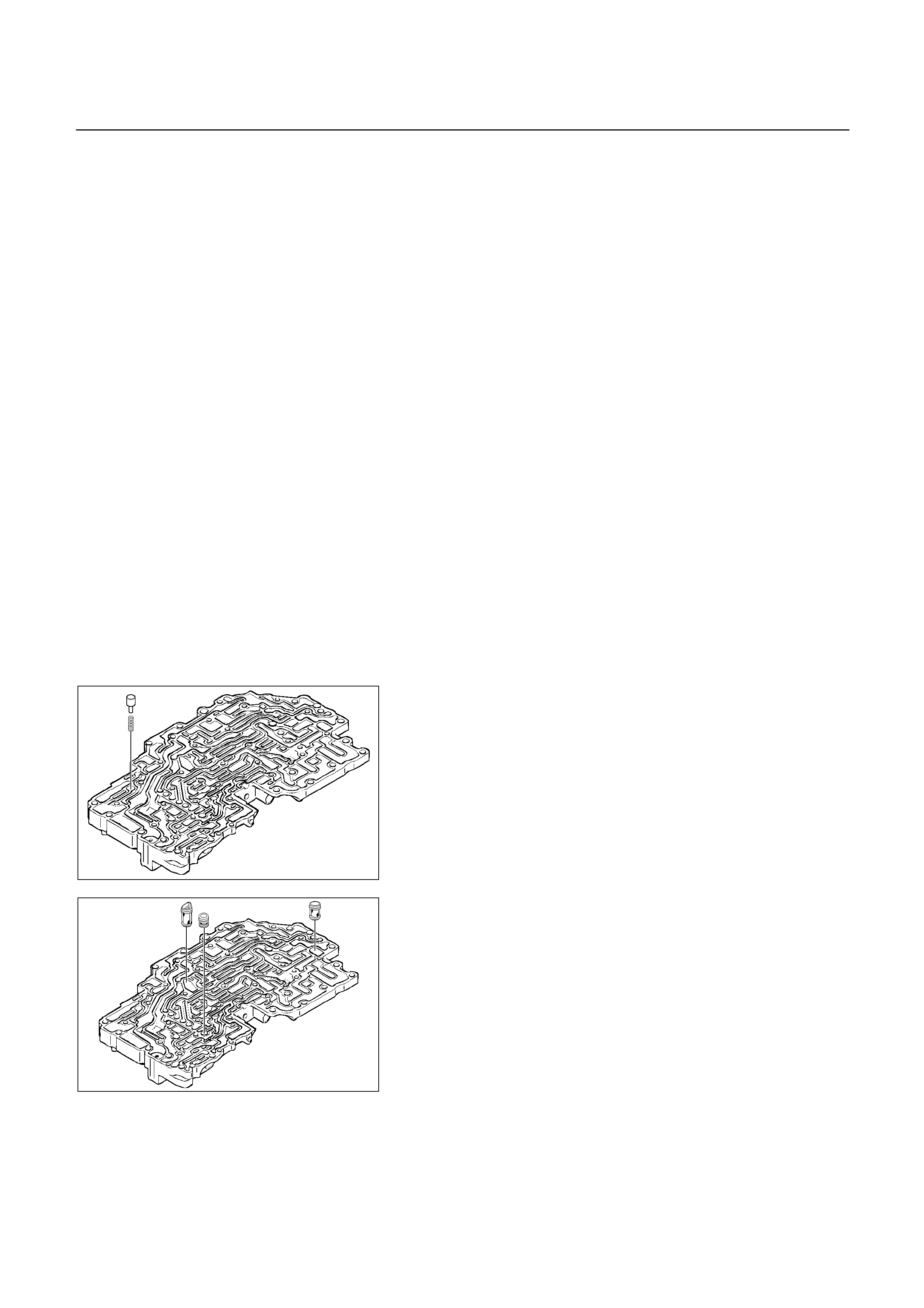
Disassembly steps
1. By-pass valve
2. Spring
3. Strainer
4. Shift solenoid S1
5. Shift solenoid S2
6. Lock-up solenoid SL
7. Clamp
8. Accumulator sub-assembly
9. Retainer
10. Spring
11. Ball
12. Retainer
13. Plug
14. Spring
15. 1-2 shift valve
16. Retainer
17. Spring
18. Low coast modulator valve
19. Retainer
20. Plug
21. Spring
22. Accumulator control valve
23. Retainer
24. Spring
25. Coast modulator valve
26. Retainer
27. Plug
28. Spring
29. Cut back valve
30. Retainer
31. Sleeve
32. Plunger
33. Plunger
34. Spring
35. Washer
36. Primary regulator valve
37. Lower valve body
244R200063
Disassembly steps
1. By-pass valve
2. Spring
Remove by-pass valve and spring.
244R200064
3. Strainer
Remove three strainers.
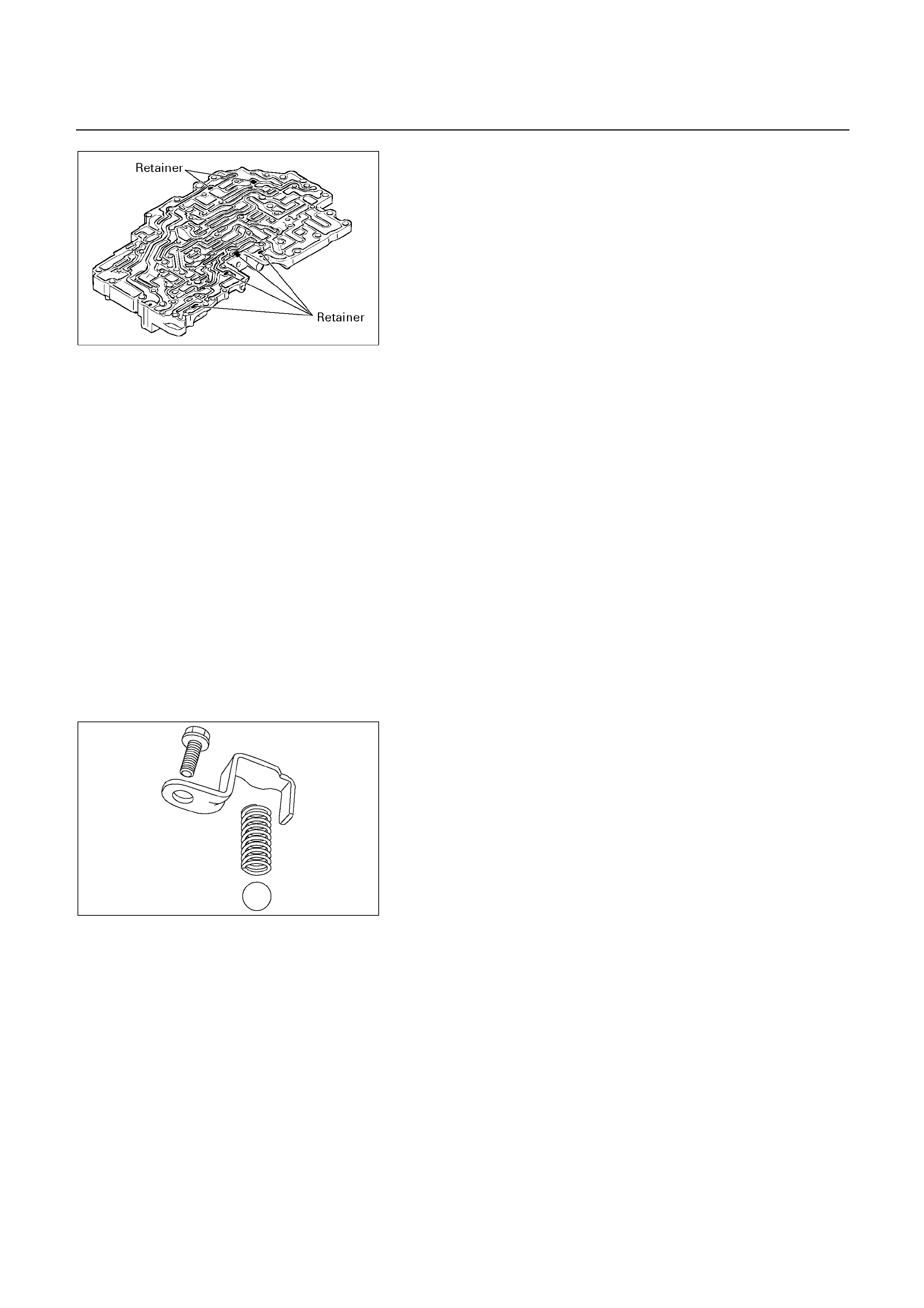
244R200066
NOTE:
Confirm six retainers are installed correctly.
4. Shift solenoid S1
5. Shift solenoid S2
Remove the fixing bolt.
Remove the shift solenoid S1 (2) and S2 (1) from each
bore.
Remove the O-rings from each solenoid.
6. Lock-up solenoid SL
Remove the fixing bolt.
Remove the lock-up solenoid SL (3) from the bore.
Remove the O-ring from solenoid.
7. Clamp
8. Accumulator sub-assembly
Remove the clamp.
Remove the accumulator sub-assembly (4) from the
bore.
244R200052
9. Retainer
10. Spring
11. Ball
Remove the retainer (5).
Remove the spring and ball from the valve body.
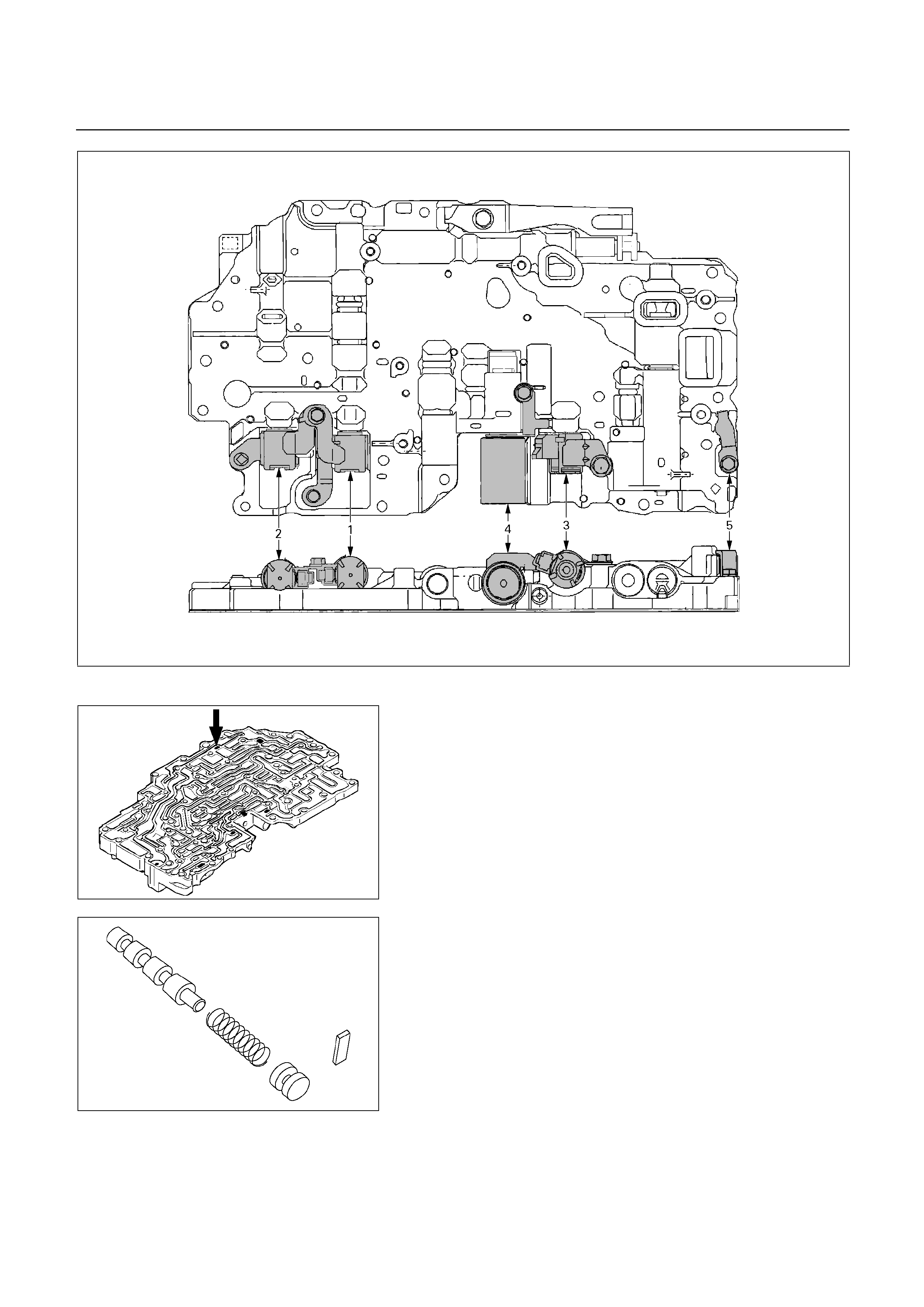
240R200042
244R200067
12. Retainer
Remove the retainer with a magnetic finger by pushing
in the plug.
13. Plug
14. Spring
15. 1-2 shift valve
Remove the plug, spring and 1-2 shift valve.
244R200054
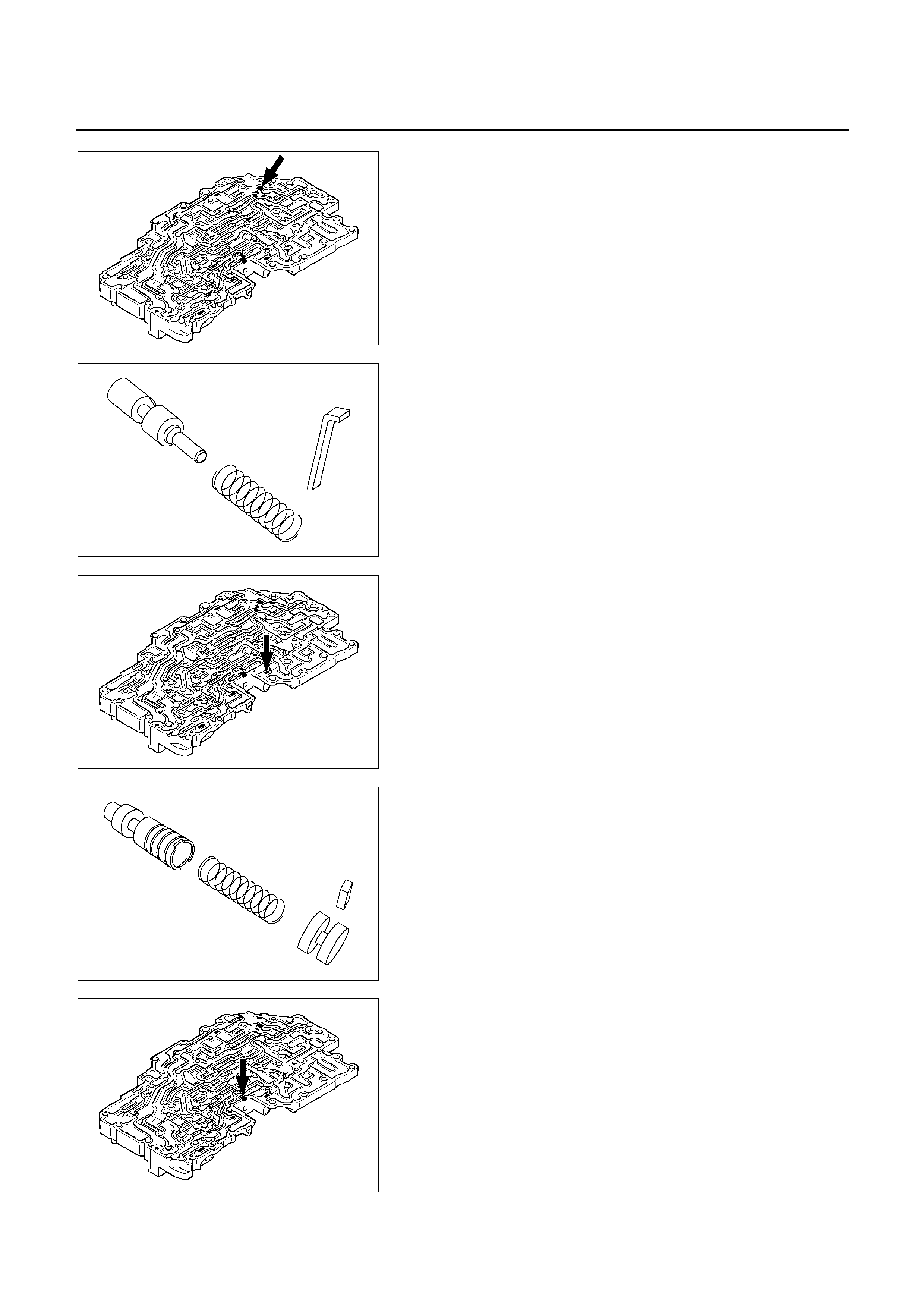
244R200068
16. Retainer
Remove the retainer by pushing in the spring with a
screwdriver.
17. Spring
18. Low coast modulator valve
Remove the spring and low coast modulator valve.
244R200056
244R200069
19. Retainer
Remove the retainer with a magnetic finger by pushing
in the plug.
20. Plug
21. Spring
22. Accumulator control valve
Remove the plug, spring and accumulator control valve.
244R200057
244R200070
23. Retainer
Remove the retainer by pushing in the spring with a
screwdriver.
24. Spring
25. Coast modulator valve
Remove the spring and coast modulator valve.
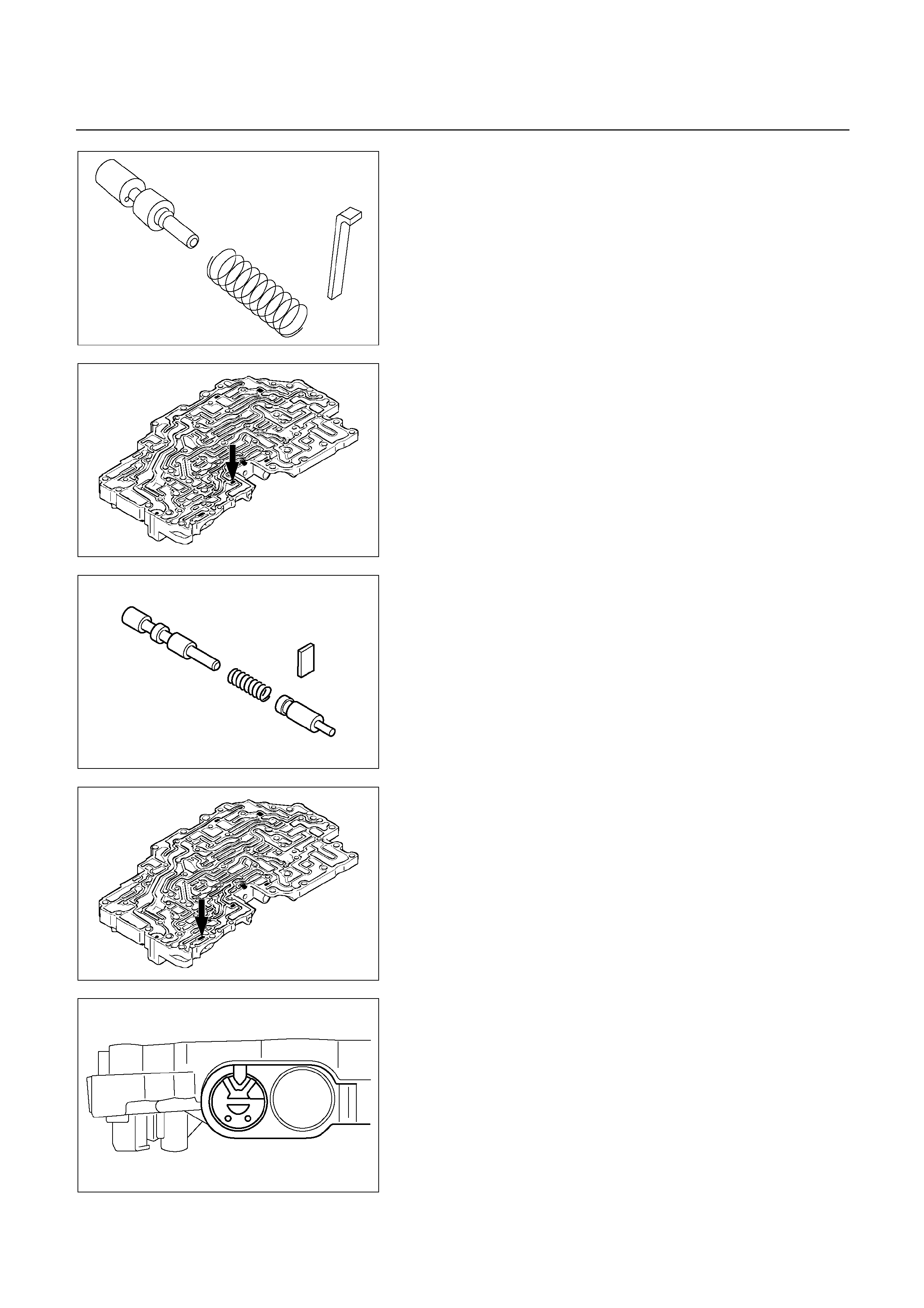
244R200058
244R200071
26. Retainer
Remove the retainer with a magnetic finger by pushing
in the plug.
27. Plug
28. Spring
29. Cut back valve
Remove the plug, spring and cut back valve.
244R200065
244R200072
244R200059
30. Retainer
Place a mark on the bevel when the retainer is
positioned.
NOTE:
When reassembling, position the retainer in the
same position.
Remove the retainer with a magnetic finger by pushing
in the sleeve.
31. Sleeve
32. Plunger
33. Plunger
34. Spring
35. Washer
36. Primary regulator valve
Remove the sleeve with the plungers, spring and
washer.
Remove the two plungers from the sleeve.

244R200060
Remove the primary regulator valve from the valve
body.
37. Lower valve body
244R200051
INSPECTION AND REPAIR
Inspect strainer
Inspect strainer for residual adhesive and damage, and
clean and replace as necessary.
Inspect valve springs
Check for damage, squareness, rust and distorted coils.
Measure the spring free height and replace if less than
shown below.
Spring Free length
(1) By-pass valve 21.3 mm (0.839 in)
(2) Steel ball 20.5 mm (0.807 in)
(3) 1-2 shift valve 30.8 mm (1.213 in)
(4) Low coast modulator valve 30.4 mm (1.197 in)
(5) Accumulator control valve 33.8 mm (1.331 in)
(6) Coast modulator valve 26.6 mm (1.047 in)
(7) Cut back valve 34.0 mm (1.339 in)
(8) Primary regulator valve 41.6 mm (1.638 in)
244R200077
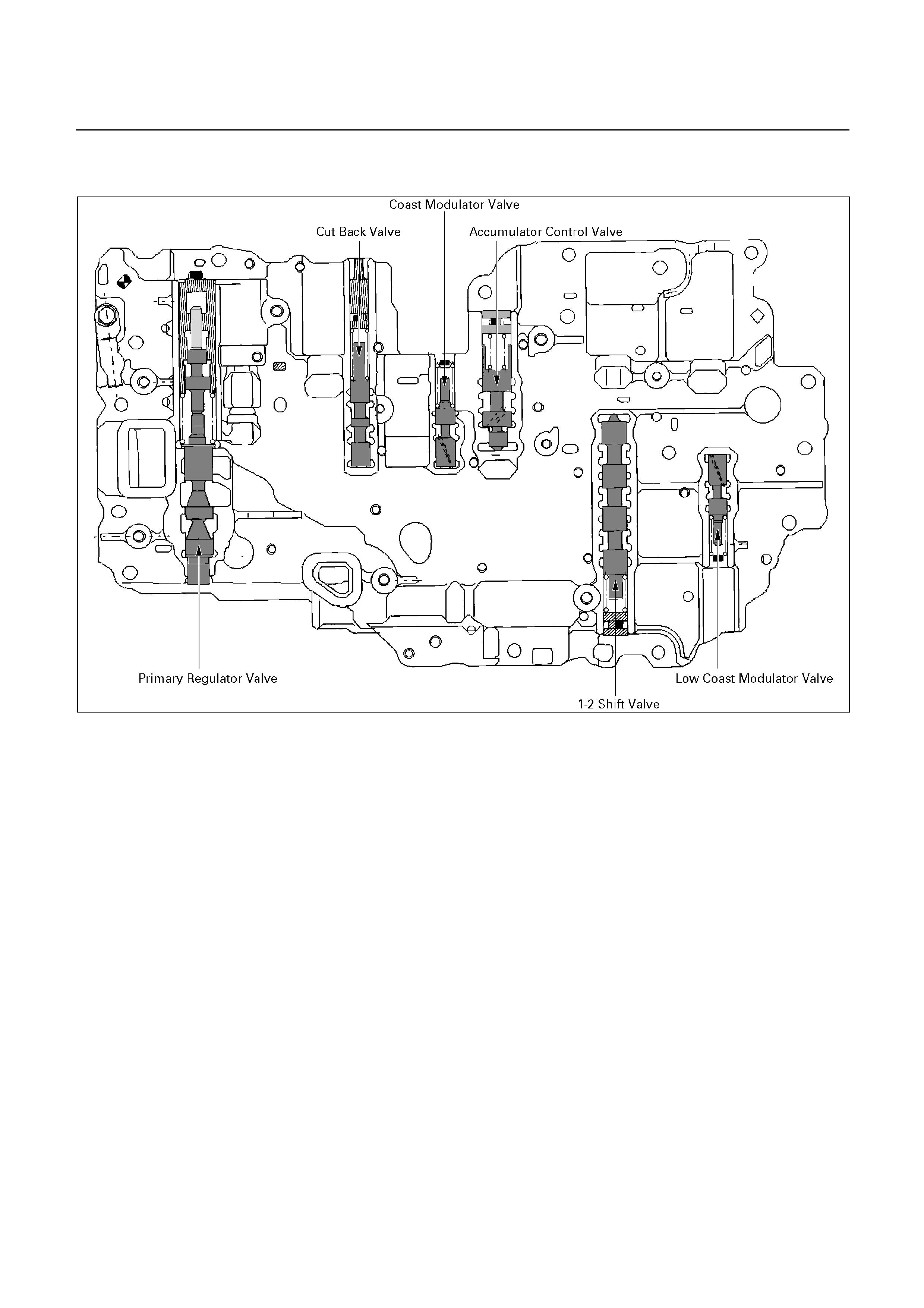
REASSEMBLY
244R200046
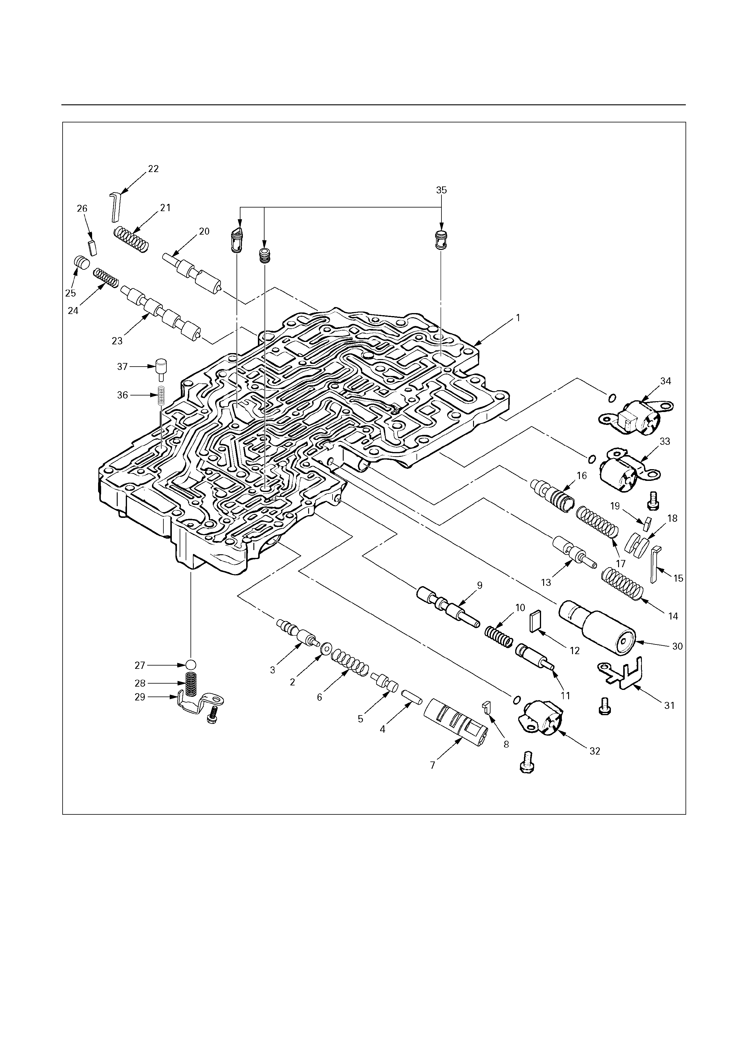
244R200076

Reassembly steps
1. Lower valve body
2. Washer
3. Primary regulator valve
4. Plunger
5. Plunger
6. Spring
7. Sleeve
8. Retainer
9. Cut back valve
10. Spring
11. Plug
12. Retainer
13. Coast modulator valve
14. Spring
15. Retainer
16. Accumulator control valve
17. Spring
18. Plug
19. Retainer
20. Low coast modulator valve
21. Spring
22. Retainer
23. 1-2 shift valve
24. Spring
25. Plug
26. Retainer
27. Ball
28. Spring
29. Retainer
30. Accumulator sub-assembly
31. Clamp
32. Lock-up solenoid SL
33. Shift solenoid S2
34. Shift solenoid S1
35. Strainer
36. Spring
37. By-pass valve
244R200060
Reassembly steps
1. Lower valve body
2. Washer
3. Primary regulator valve
Install the washer onto the primary regulator valve.
Install the primary regulator valve with the washer into
the bore.
4. Plunger
5. Plunger
Install the two plungers into the sleeve.
6. Spring
7. Sleeve
Install the sleeve with the two plungers and spring into
the bore.
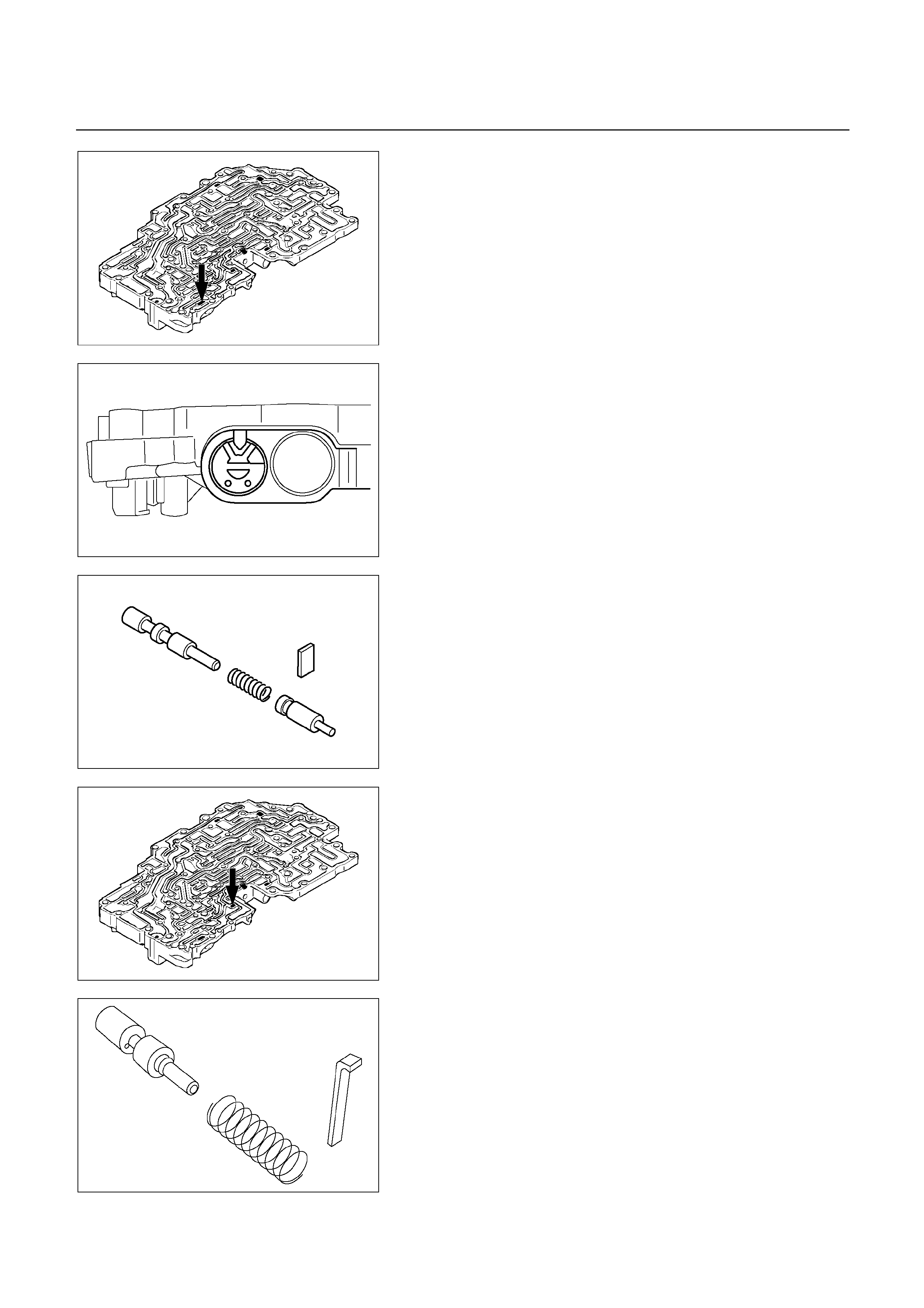
244R200072
8. Retainer
Install the retainer to the bevel by pushing in the sleeve.
NOTE:
Install the retainer to the same position on the
sleeve, as when disassembling.
244R200059
244R200065
9. Cut back valve
10. Spring
11. Plug
Install the cut back valve, spring and plug into the bore.
12. Retainer
Install the retainer by pushing in the plug.
244R200071
244R200058
13. Coast modulator valve
14. Spring
15. Retainer
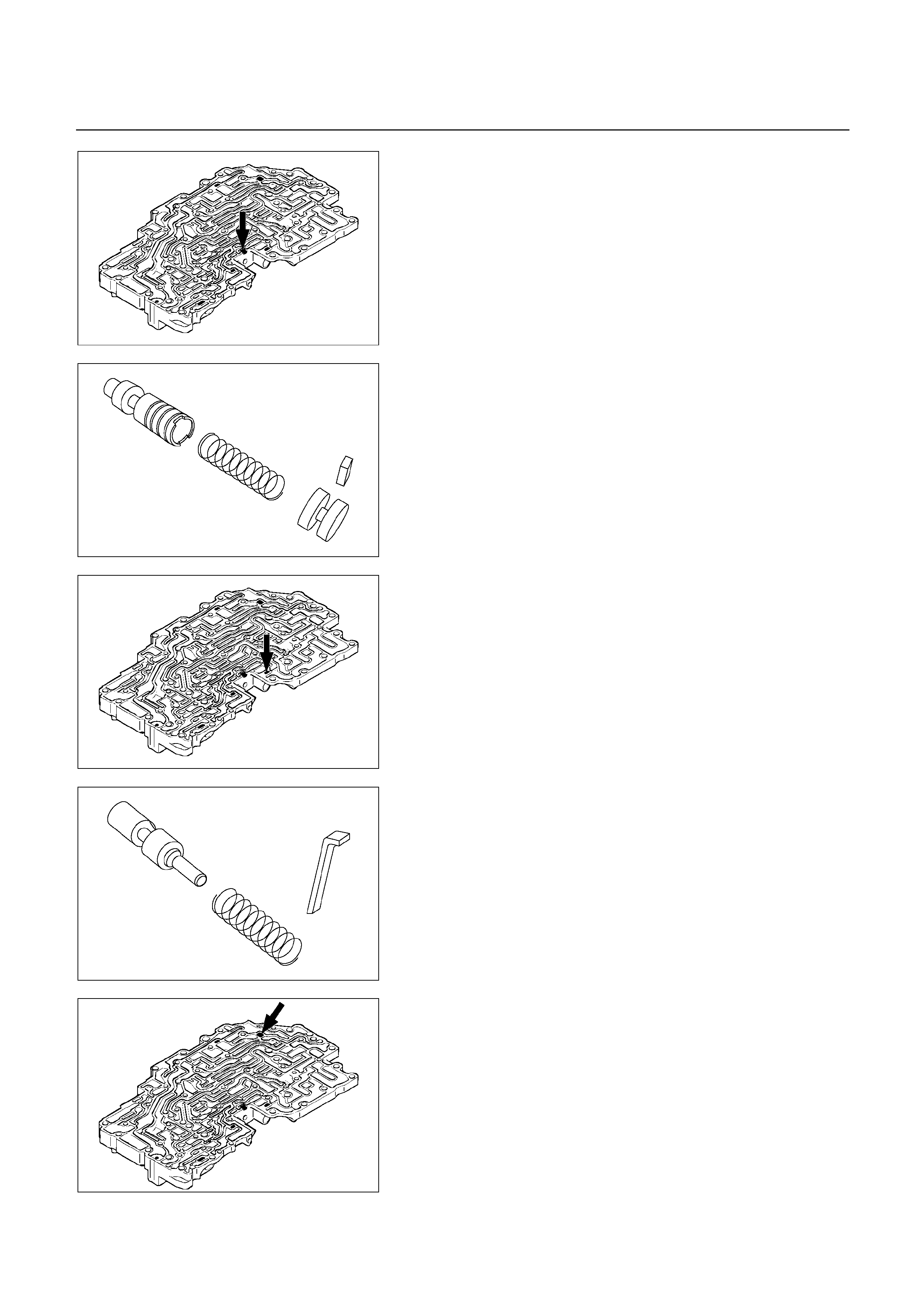
244R200070
244R200057
16. Accumulator control valve
17. Spring
18. Plug
Install the accumulator control valve, spring and plug
into the bore.
19. Retainer
Install the retainer by pushing in the plug.
244R200069
244R200056
20. Low coast modulator valve
21. Spring
Install the low coast modulator valve and spring into the
bore.
22. Retainer
Install the retainer by pushing in the spring.
244R200068
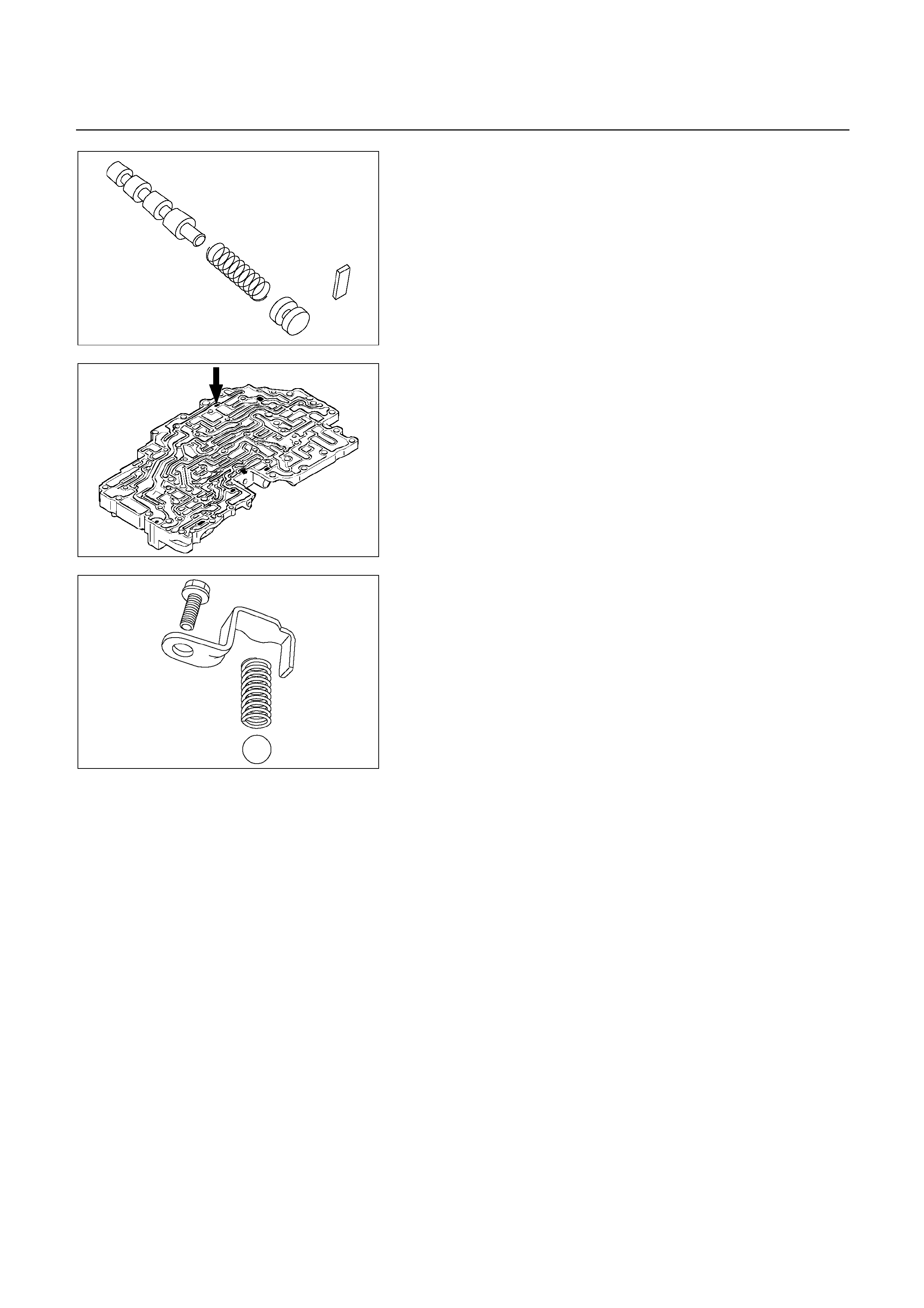
244R200054
23. 1-2 shift valve
24. Spring
25. Plug
Install the 1-2 shift valve, spring and plug into the bore.
26. Retainer
Install the retainer by pushing in the plug.
244R200067
244R200052
27. Ball
28. spring
29. Retainer
Install the ball, spring and retainer (5) to the valve body.
Torque: 10 N m (1.0 kg m/87 Ib in)
30. Accumulator sub-assembly
31. Clamp
Install the accumulator sub-assembly (4) and clamp to
the valve body.
Torque: 10 N m (1.0 kg m/87 Ib in)
32. Lock-up solenoid SL
Install a new O-ring to the solenoid (3).
Install the solenoid to the valve body.
Torque: 10 N m (1.0 kg m/87 Ib in)
33. Shift solenoid S2
34. Shift solenoid S1
Install a new O-ring to the solenoids (1) and (2).
Install the solenoids to the valve body.
Torque: 10 N m (1.0 kg m/87 Ib in)
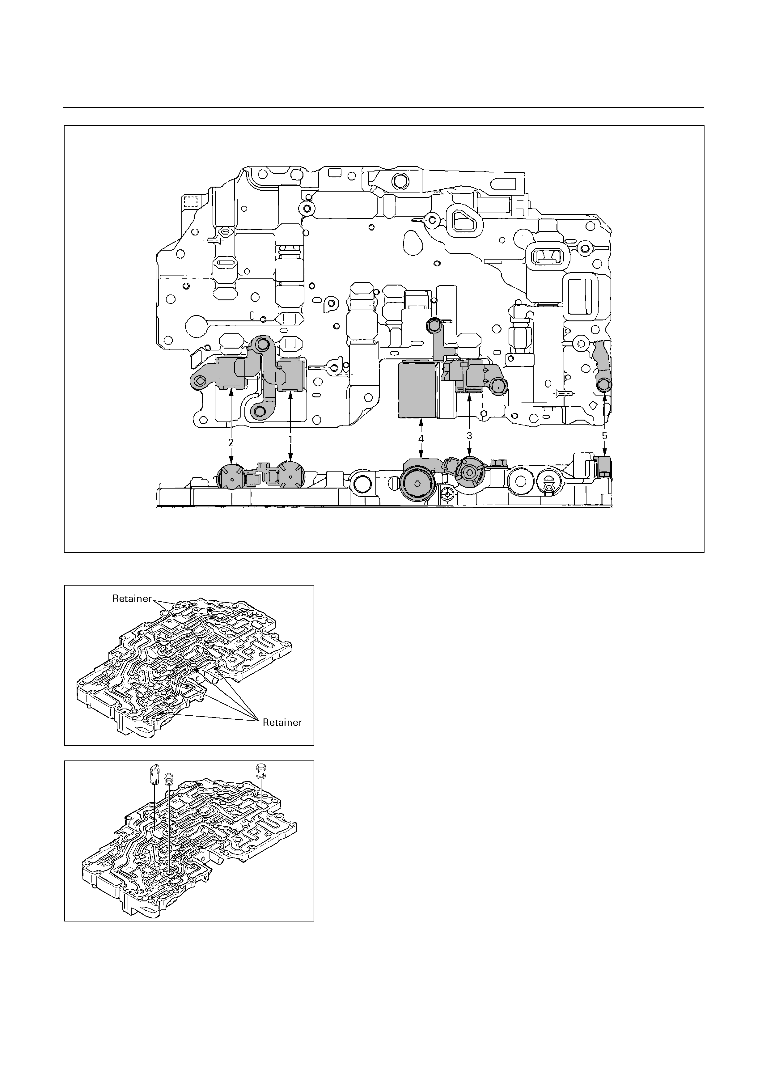
240R200042
244R200066
NOTE:
Make sure six retainers are installed correctly.
244R200064
35. Strainer
Install the three strainers to the valve body as shown.

244R200063
36. Spring
37. By-pass valve
Install the spring and by-pass valve to the valve body as
shown.
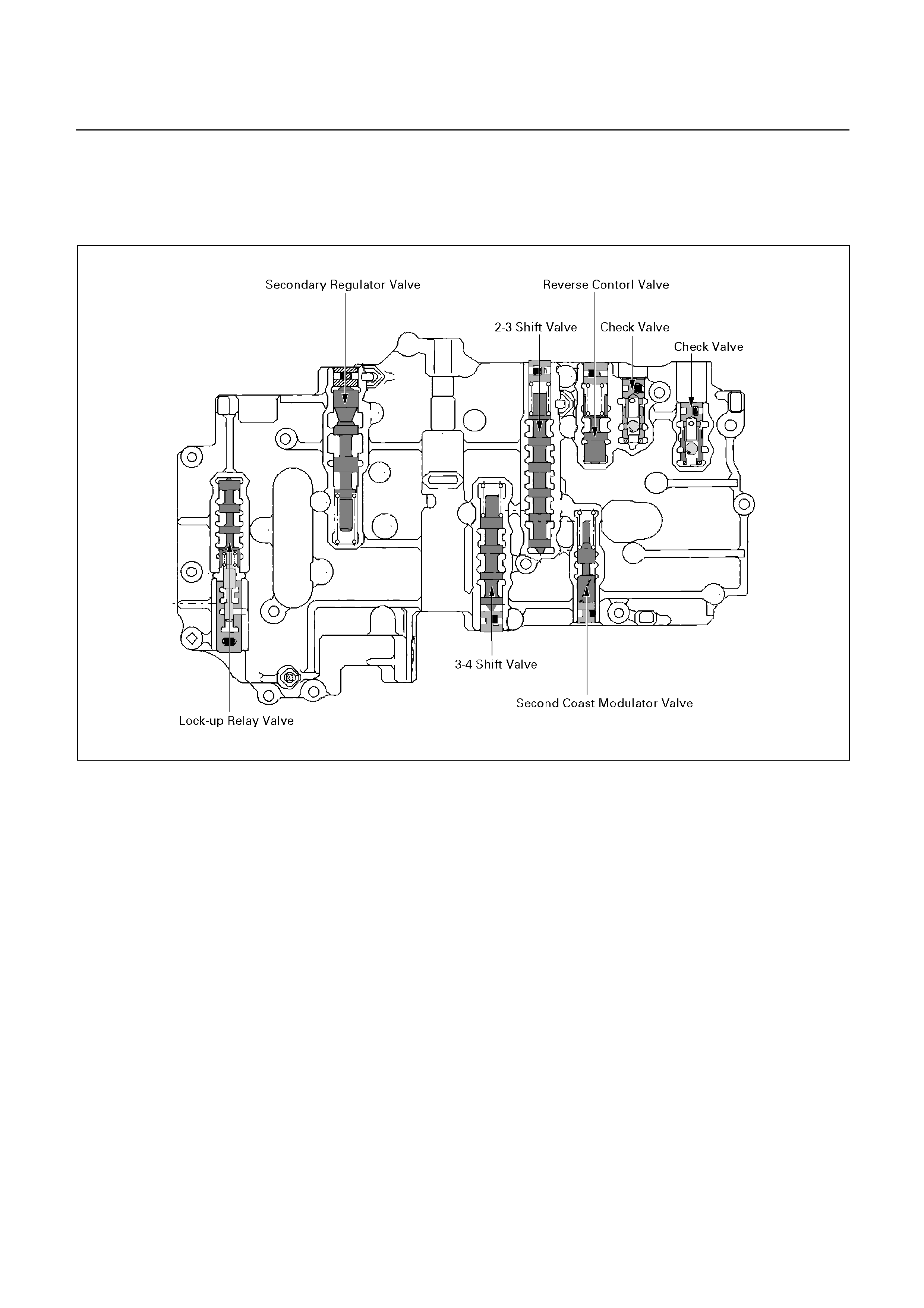
UPPER VALVE BODY
DISASSEMBLY
243R200052
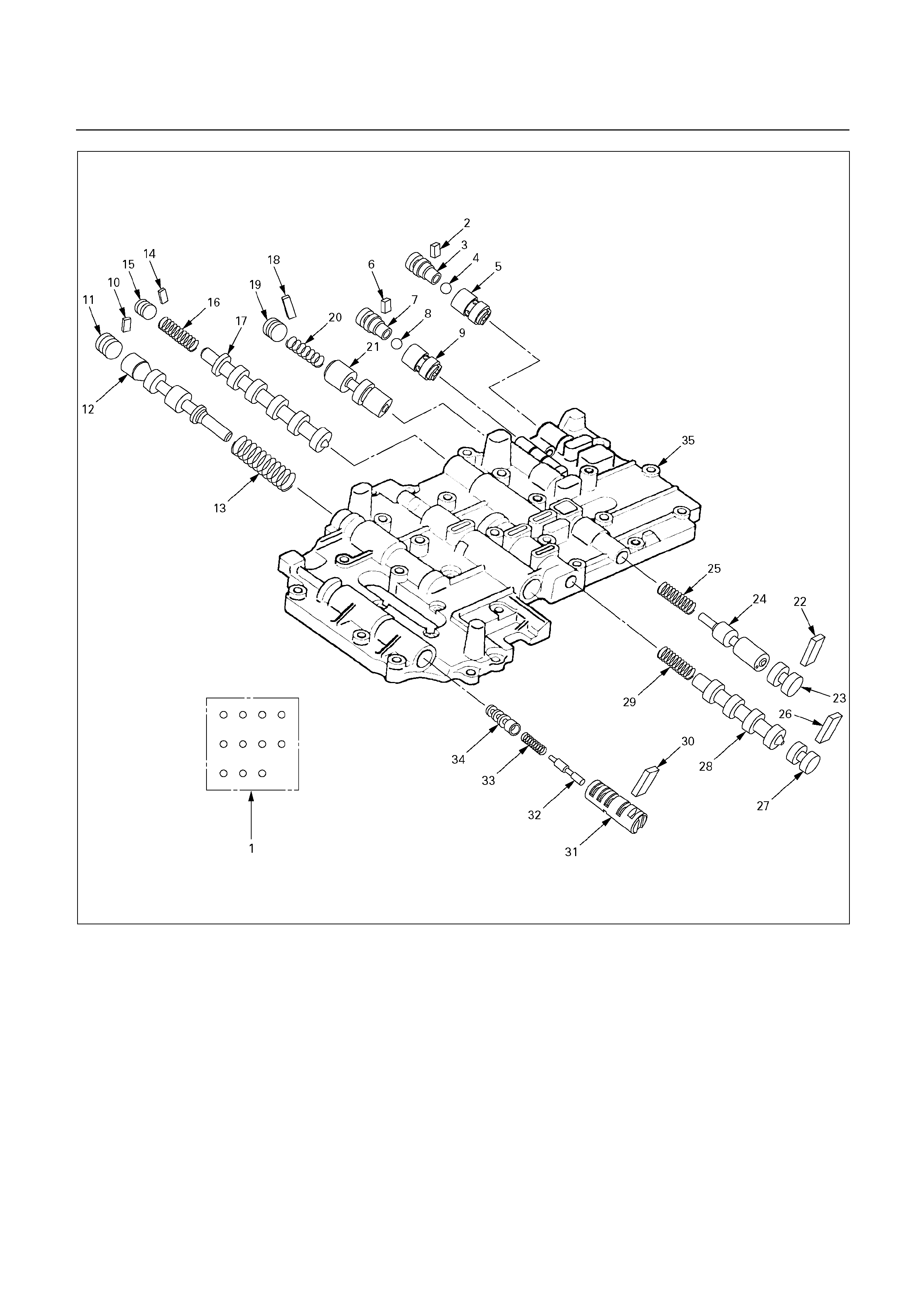
243R200074
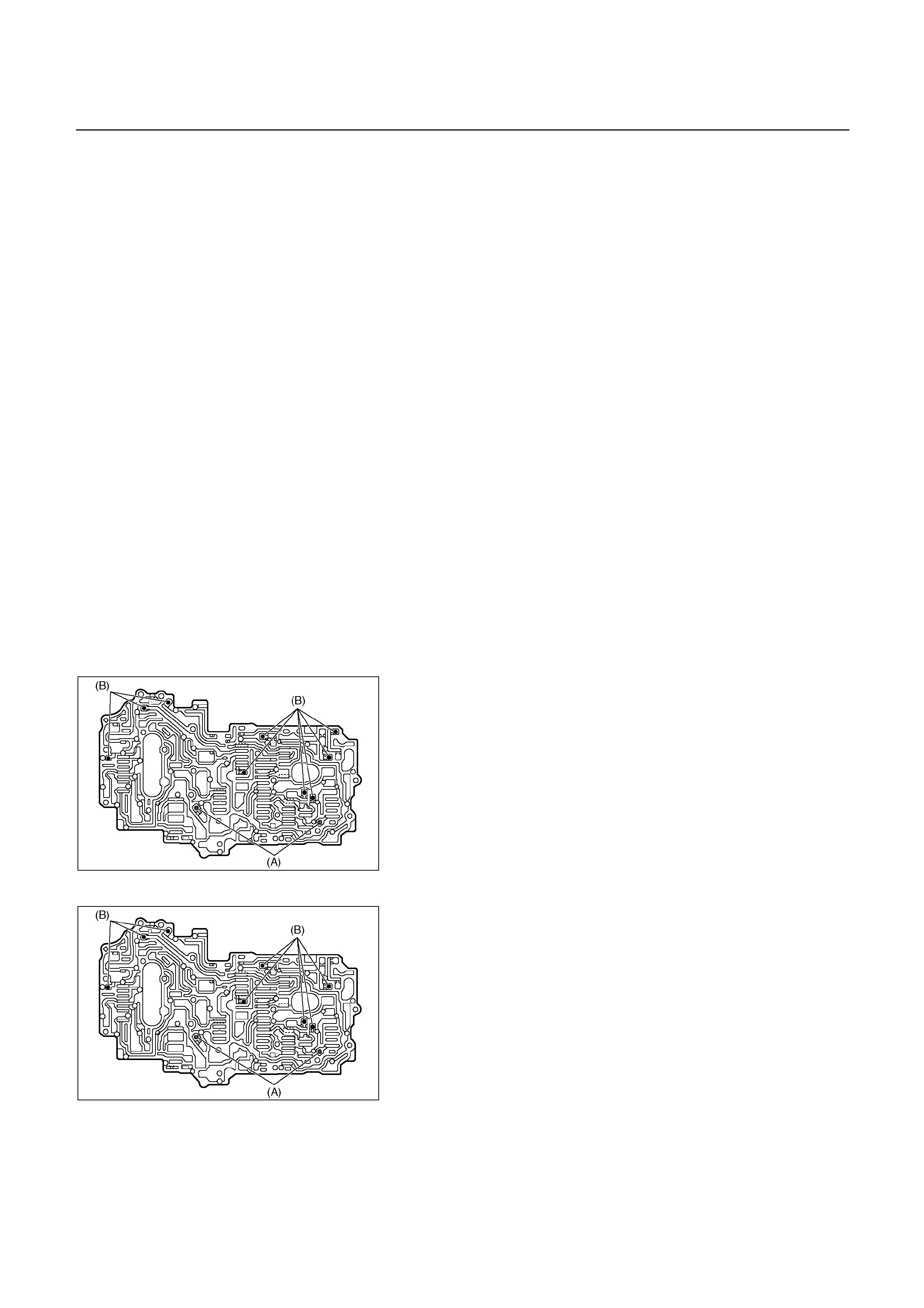
Disassembly steps
1. Check ball
2. Retainer
3. Check valve NO.2
4. Ball
5. Check valve NO.1
6. Retainer
7. Check valve NO.2
8. Ball
9. Check valve NO.1
10. Retainer
11. Plug
12. Secondary regulator valve
13. Spring
14. Retainer
15. Plug
16. Spring
17. 2-3 shift valve
18. Retainer
19. Plug
20. Spring
21. Reverse control valve
22. Retainer
23. Plug
24. Second coast modulator valve
25. Spring
26. Retainer
27. Plug
28. 3-4 shift valve
29. Spring
30. Retainer
31. Sleeve
32. Plunger
33. Spring
34. Lock-up relay valve
35. Upper valve body
UBS
243R200053
Disassembly steps
1. Check ball
Remove the two types of check balls from the valve
body.
Number of check ball : UBS 11
TFR/S 10
TFR/S
243L200001
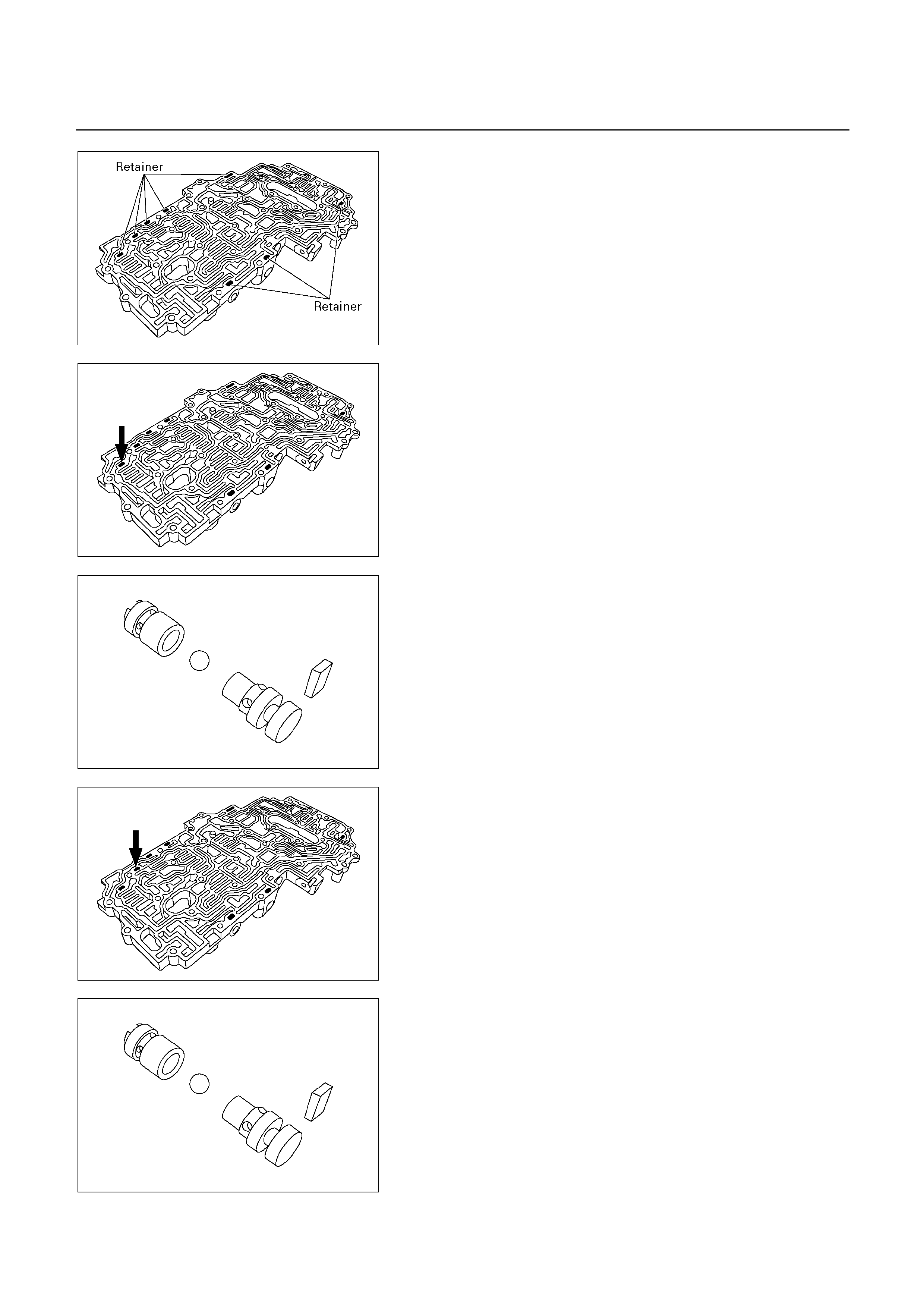
243R200054
NOTE:
Confirm eight retainers are installed correctly.
243R200066
2. Retainer
3. Check valve NO.2
4. Ball
5. Check valve NO.1
Remove the check valve NO.2 ball and check valve
NO.1 from the valve body.
243R200062
243R200067
6. Retainer
7. Check valve NO.2
8. Ball
9. Check valve NO.1
Remove the check valve NO.2, ball and check valve
NO.1 from the valve body.
243R200062
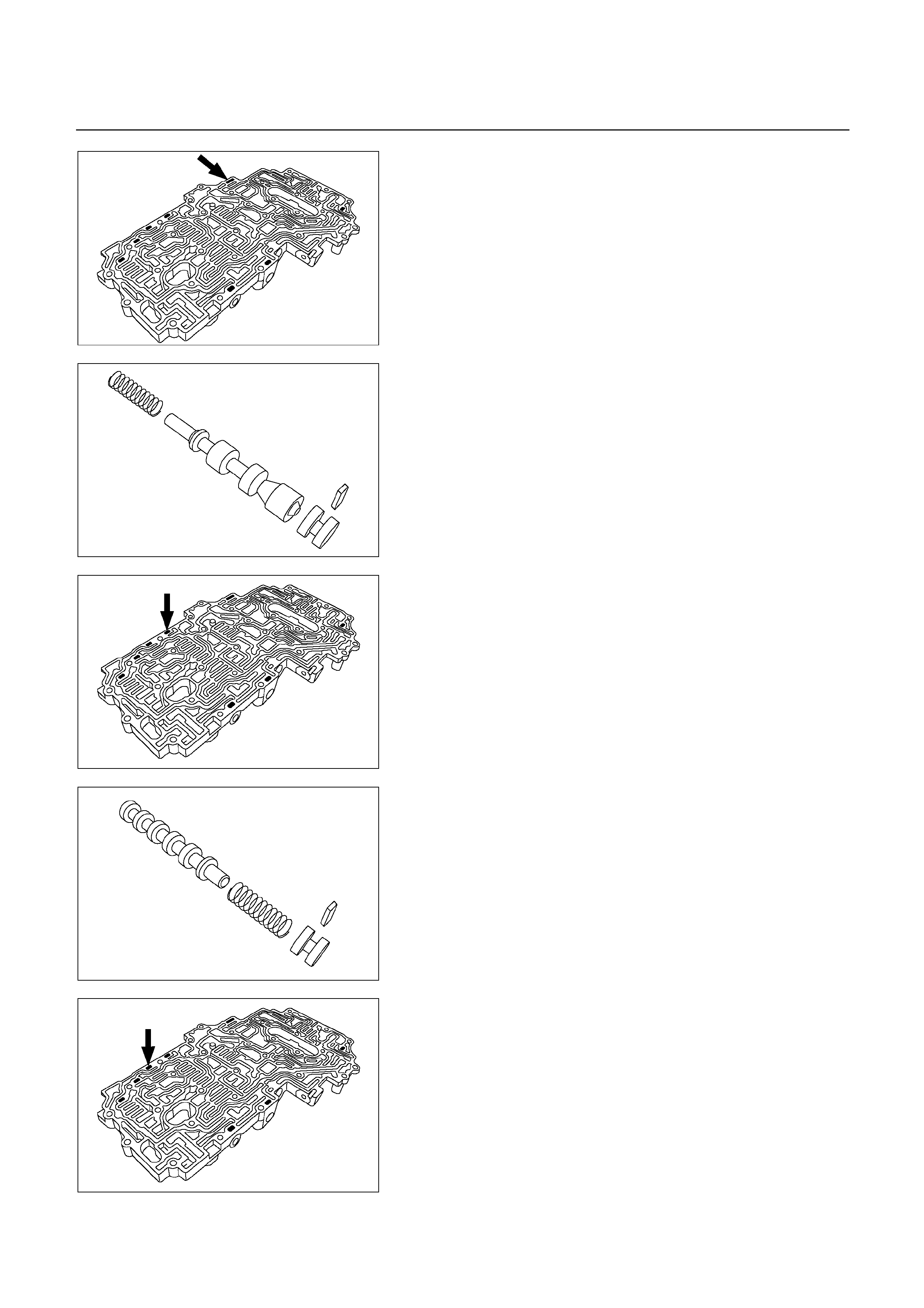
243R200070
10. Retainer
Remove the retainer with a magnetic finger by pushing
in the plug.
11. Plug
12. Secondary regulator valve
13. Spring
Remove the plug, secondary regulator valve and spring.
243R200056
243R200069
14. Retainer
Remove the trainer with a magnetic finger by pushing in
the plug.
15. Plug
16. Spring
17. 2-3 shift valve
Remove the plug, spring and 2-3 shift valve.
243R200058
243R200068
18. Retainer
Remove the retainer with a magnetic finger by pushing
in the plug.
19. Plug
20. Spring
21. Reverse control valve
Remove the plug, spring and reverse control valve.
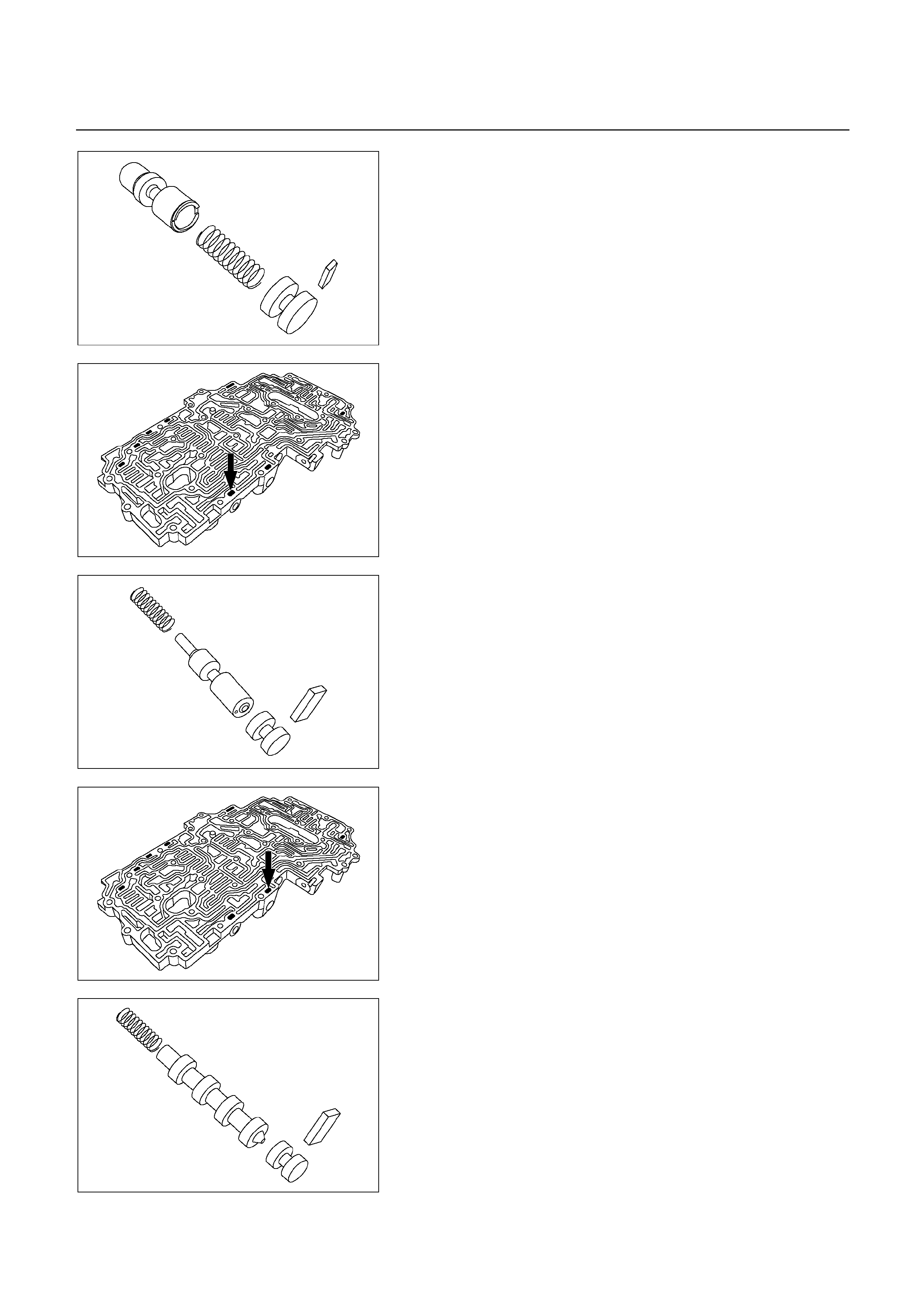
243R200060
243R200073
22. Retainer
Remove the retainer with a magnetic finger by pushing
in the plug.
23. Plug
24. Second coast modulator valve
25. Spring
Remove the plug, second coast modulator valve and
spring.
243R200063
243R200072
26. Retainer
Remove the retainer with a magnetic finger by pushing
in the plug.
27. Plug
28. 3-4 shift valve
29. Spring
Remove the plug, 3-4 shift valve and spring.
243R200064
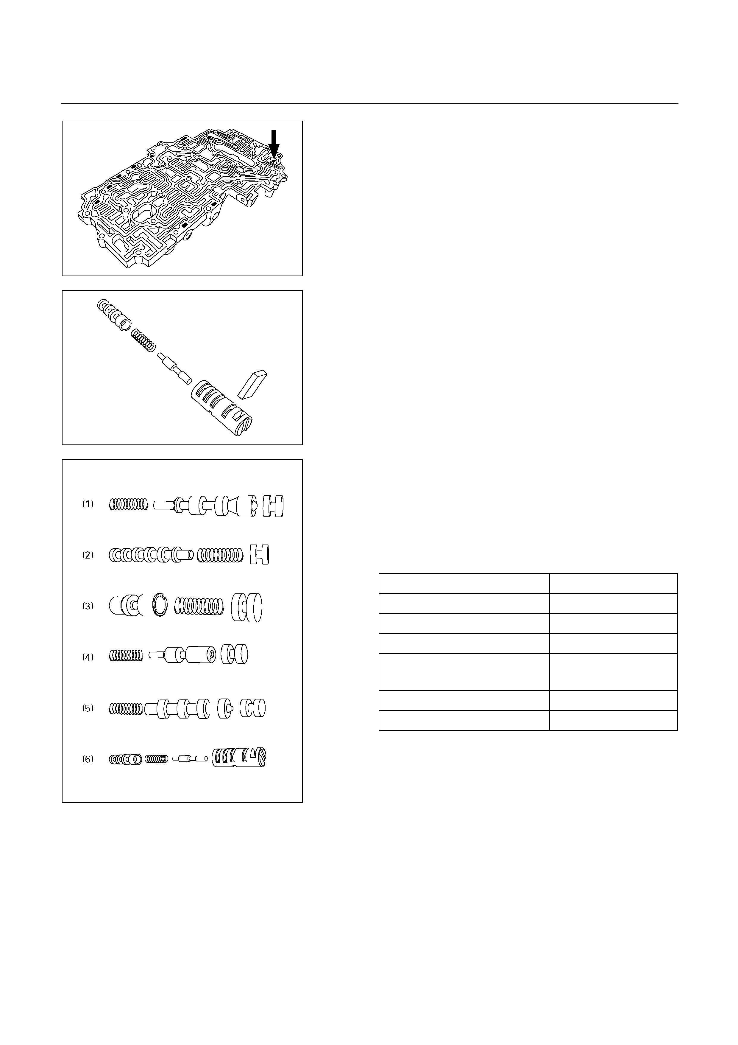
243R200071
243R200065
30. Retainer
Remove the retainer with a magnetic finger by pushing
in the sleeve.
31. Sleeve
32. Plunger
33. Spring
34. Lock-up relay valve
Remove the sleeve with the plunger, spring and lock-up
relay valve.
Remove the lock-up relay valve, spring and plunge
r
from the sleeve.
35. Upper valve body
INSPECTION AND REPAIR
Inspect valve springs
Check for damage, squareness, rust and distorted coils.
Measure the spring free height and replace if less than
that down below.
Spring Free length
(1) secondary regulator valve 32.9 mm (1.295 in)
(2) 2-3 shift valve 30.8 mm (1.213 in)
(3) Reverse control valve 25.6 mm (1.008 in)
(4) Second coast modulator
valve 30.9 mm (1.217 in)
(5) 3-4 shift valve 30.8 mm (1.213 in)
(6) Lock-up relay valve 23.4 mm (0.912 in)
243R200076
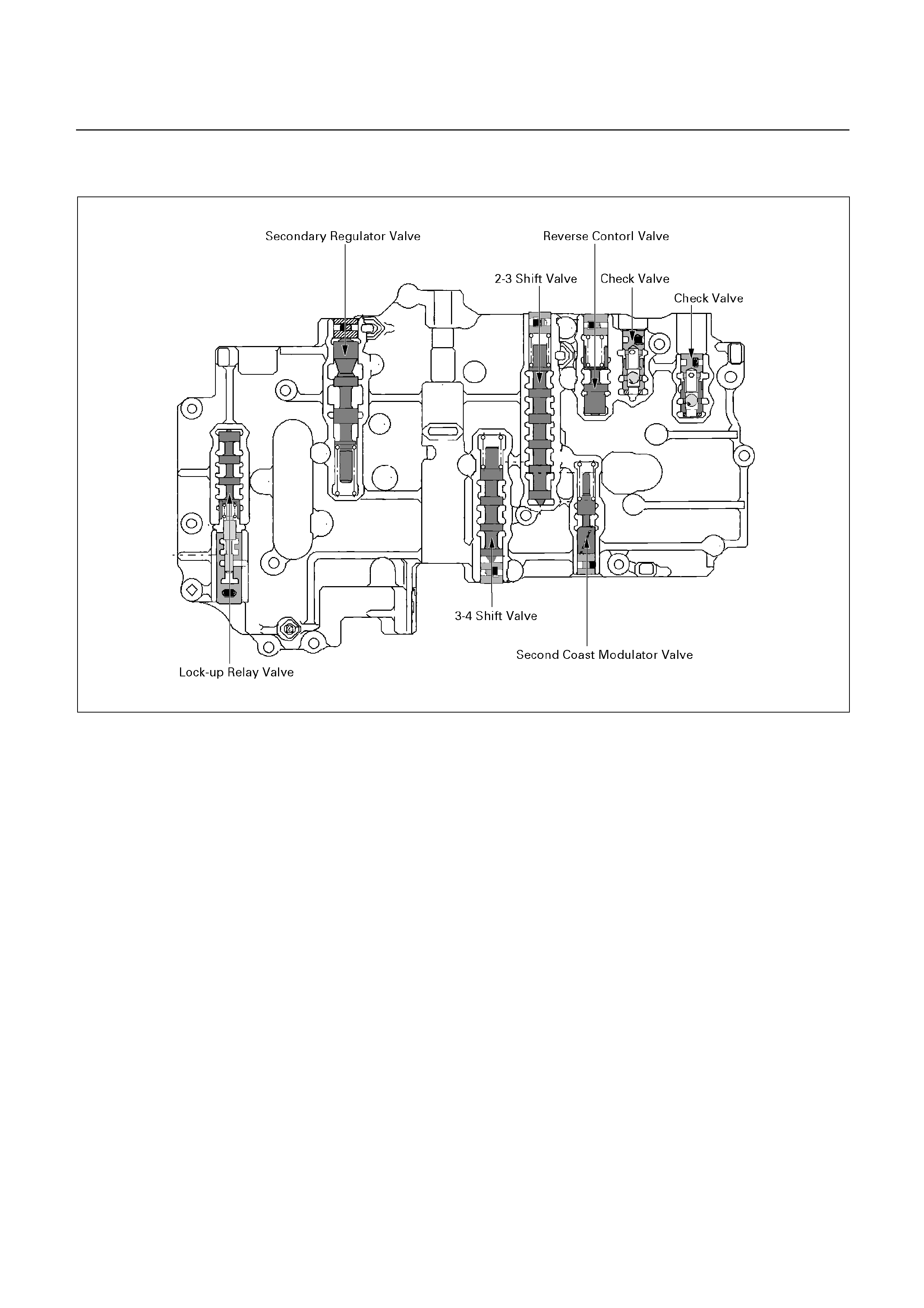
REASSEMBLY
243R200052
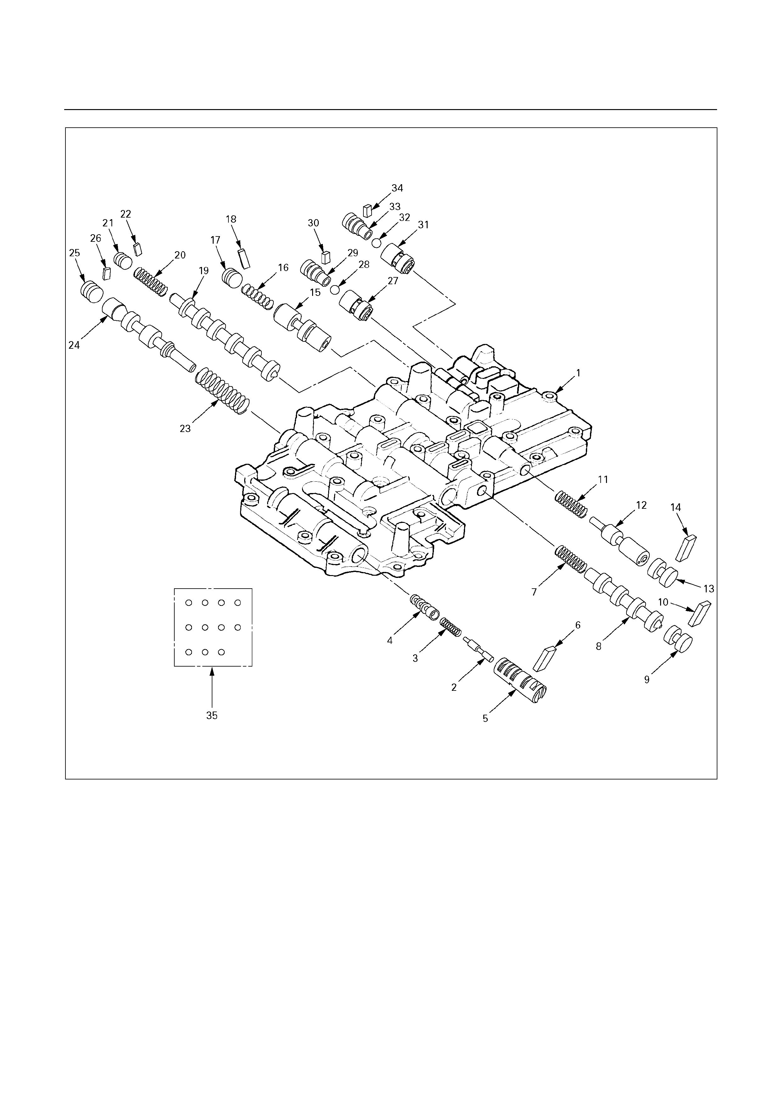
243R200075
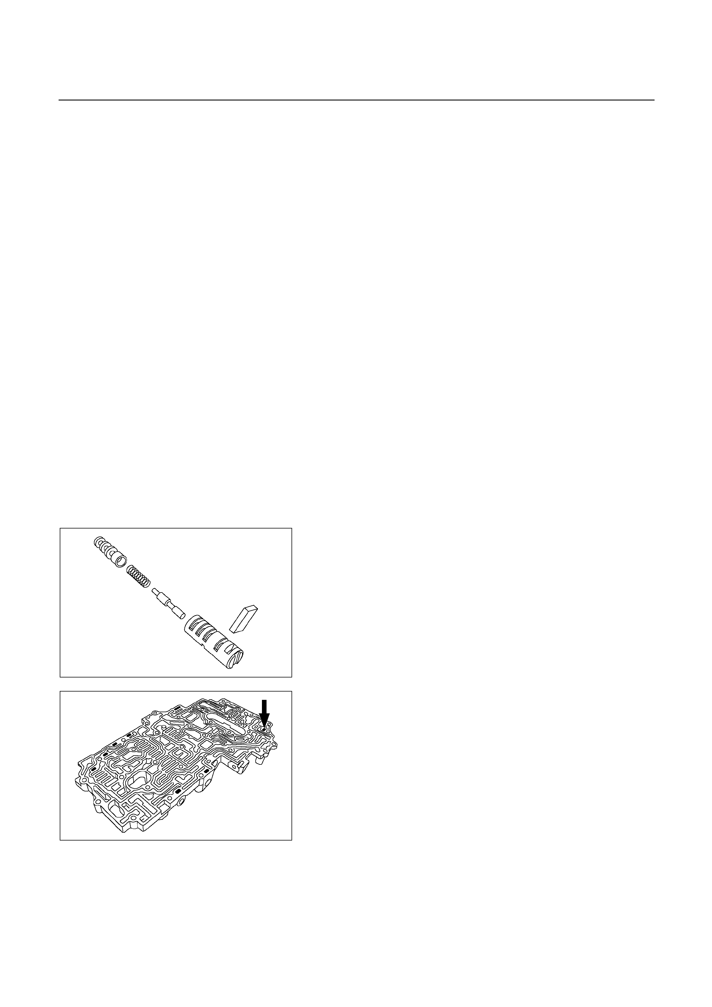
Reassembly steps
1. Upper valve body
2. Plunger
3. Spring
4. Lock-up relay valve
5. Sleeve
6. Retainer
7. Spring
8. 3-4 shift valve
9. Plug
10. Retainer
11. Spring
12. Second coast modulator valve
13. Plug
14. Retainer
15. Reverse control valve
16. Spring
17. Plug
18. Retainer
19. 2-3 shift valve
20. Spring
21. Plug
22. Retainer
23. Spring
24. Secondary regulator valve
25. Plug
26. Retainer
27. Check valve NO.1
28. Ball
29. Check valve NO.2
30. Retainer
31. Check valve NO.1
32. Ball
33. Check valve NO.2
34. Retainer
35. Check ball
243R200065
243R200071
Reassembly steps
1. Upper valve body
2. Plunger
3. Spring
4. Lock-up relay valve
5. Sleeve
Install the plunger and spring into the sleeve.
Install the lock-up relay valve into the sleeve.
Install the sleeve with the plunger, spring and lock-up
relay valve into the bore.
6. Retainer
Install the retainer.
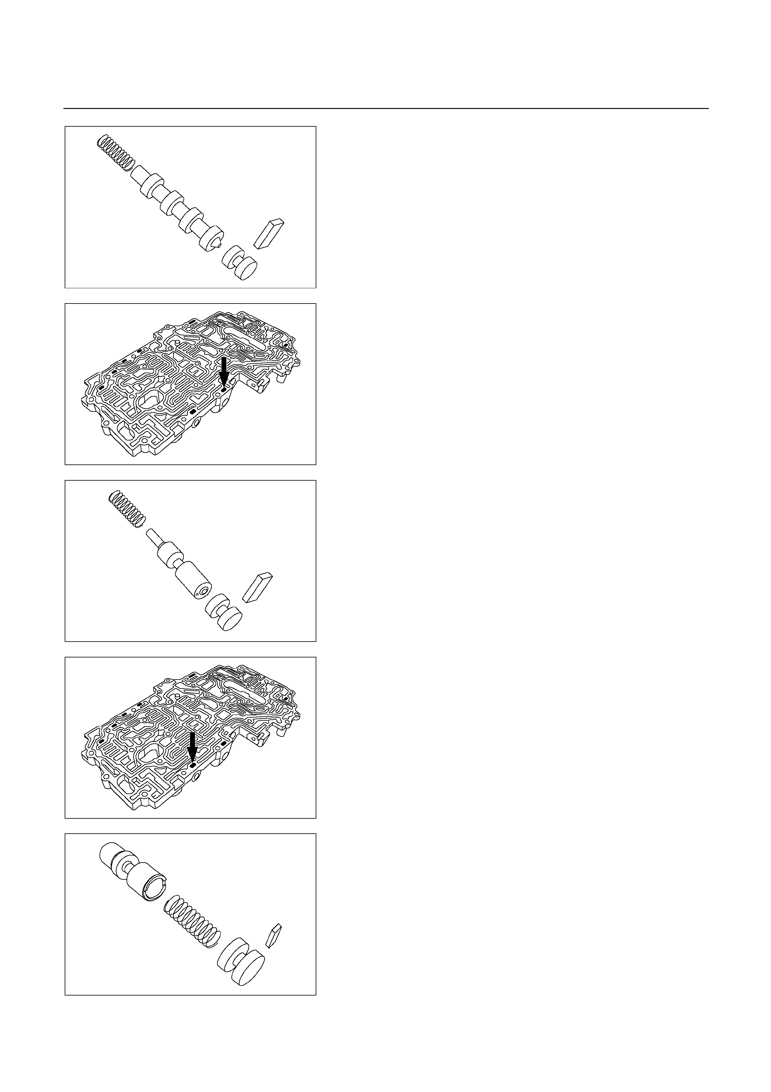
243R200064
7. Spring
8. 3-4 shift valve
9. Plug
Install the spring, 3-4 shift valve and plug into the bore.
10. Retainer
Install the retainer by pushing in the plug.
243R200072
243R200063
11. Spring
12. Secondary regulator valve
13. Plug
Install the spring, second coast modulator valve and
plug into the bore.
14. Retainer
Install the retainer by pushing in the plug.
243R200073
243R200060
15. Reverse control valve
16. Spring
17. Plug
Install the reverse control valve, spring and plug into the
bore.
18. Retainer
Install the retainer by pushing in the plug.
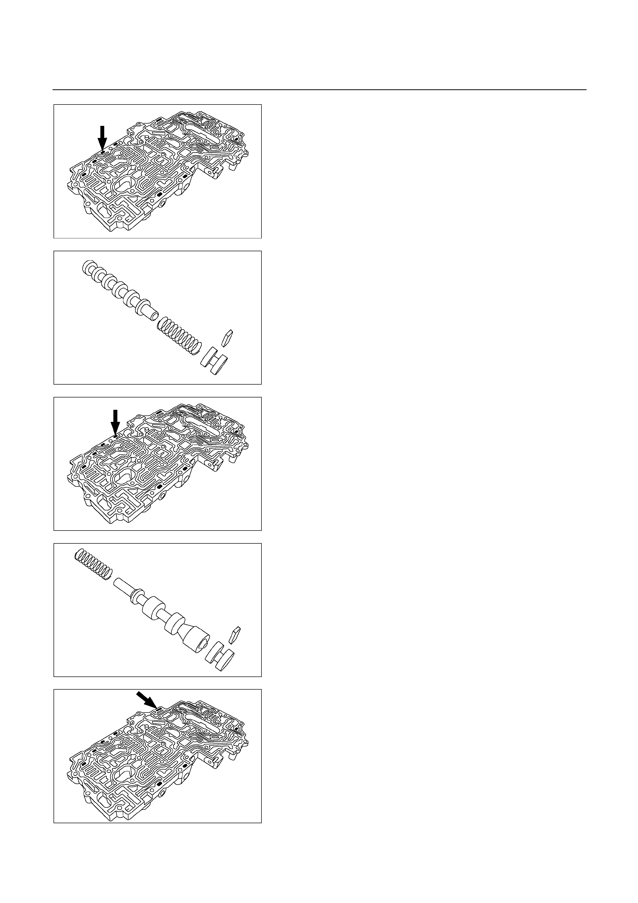
243R200068
243R200058
19. 2-3 shift valve
20. Spring
21. Plug
Install the 2-3 valve, spring and plug into the bore.
22. Retainer
Install the retainer by pushing in the plug.
243R200069
243R200056
23. Spring
24. Secondary regulator valve
25. Plug
Install the spring, secondary regulator valve and plug
into the bore.
26. Retainer
Install the retainer by pushing in the plug.
243R200070
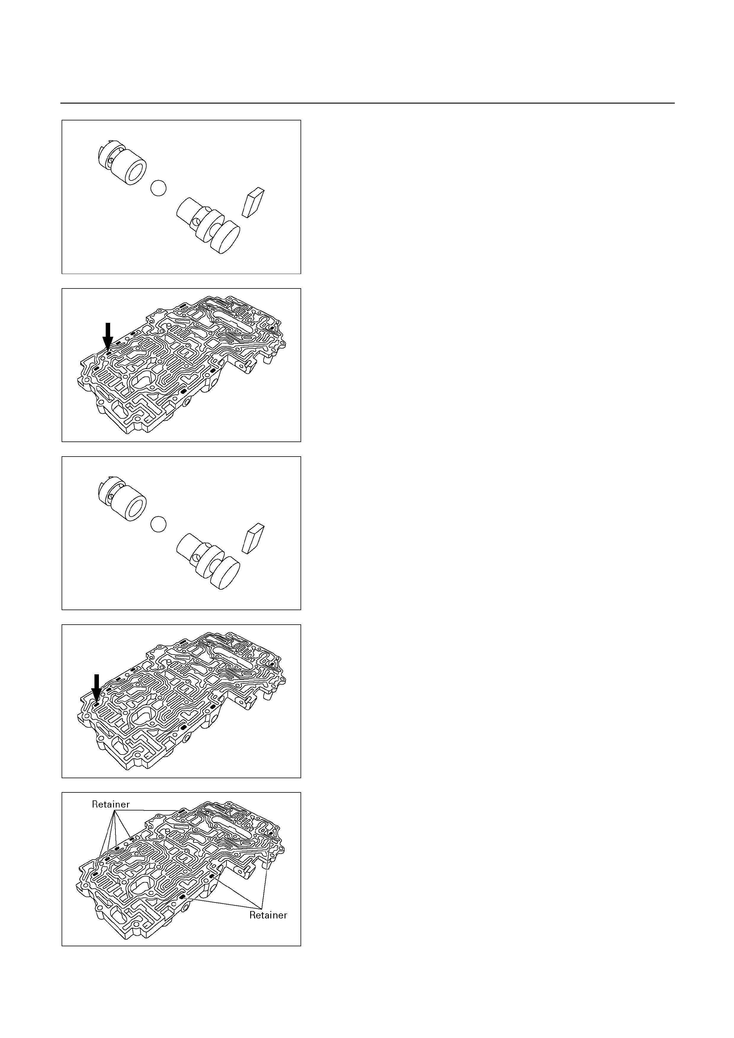
243R200062
27. Check valve NO.1
28. Ball
29. Check valve NO.2
Install the check valve NO.1, ball and check valve NO.2
to valve body.
30. Retainer
243R200067
243R200062
31. Check valve NO.1
32. Ball
33. Check valve NO.2
Install the check valve NO.1, ball and check valve NO.2
to the valve body.
34. Retainer
243R200066
243R200054
NOTE:
Make sure eight retainers are installed correctly
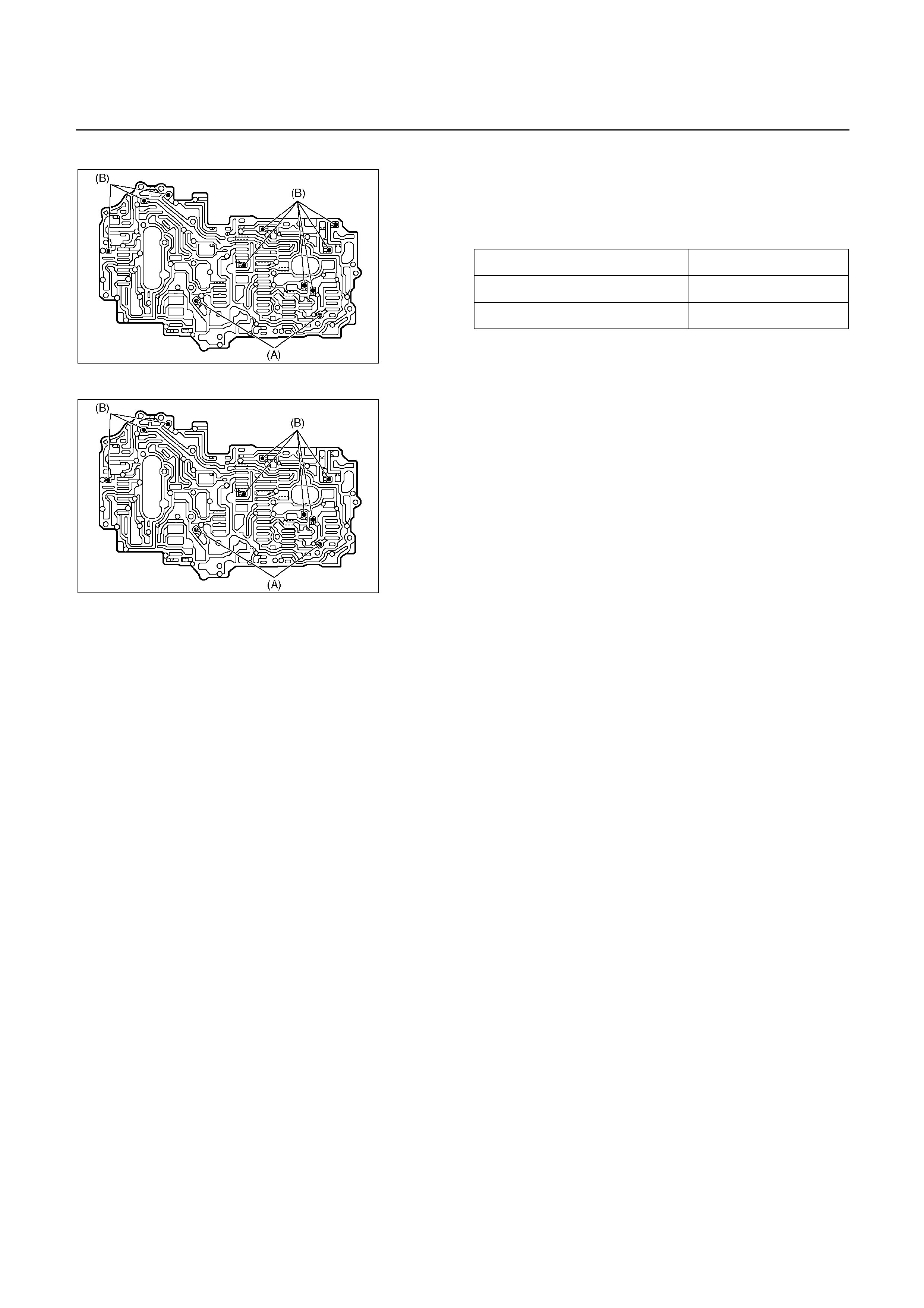
35. Check ball
Install the two types of check balls to the valve body.
Number of check ball : UBS – 11
TFR/S – 10
Check ball Diameter
(A) Rubber ball 5.535 mm (0.2179 in)
(B) Rubber ball 6.35 mm (0.2500 in)
UBS
243R200053
TFR/S
243L200001
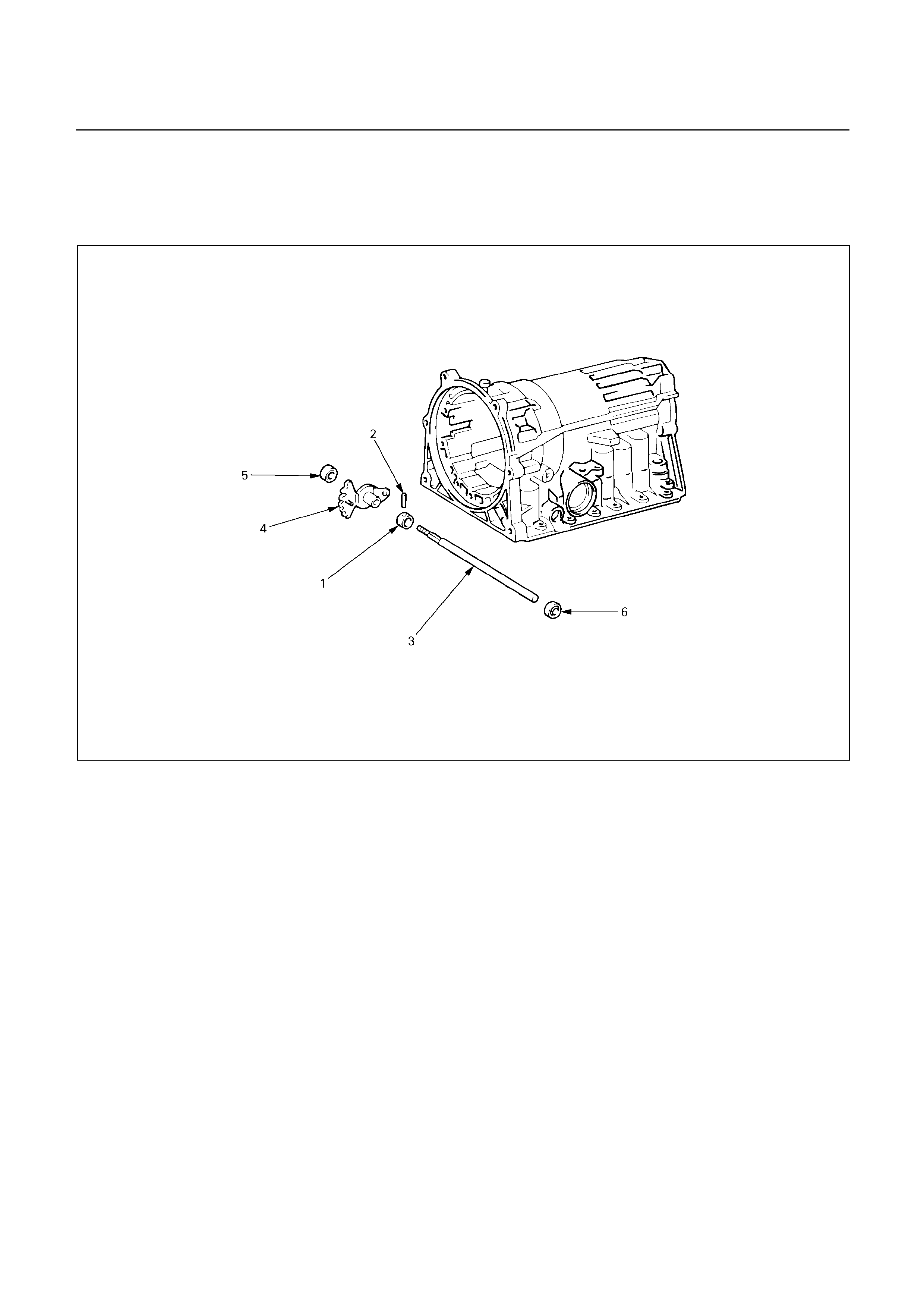
TRANSMISSION CASE
DISASSEMBLY
249RY00001
Disassembly steps
1. Spacer
2. Pin
3. Manual valve lever shaft
4. Manual valve lever
5. Oil seal
6. Oil seal
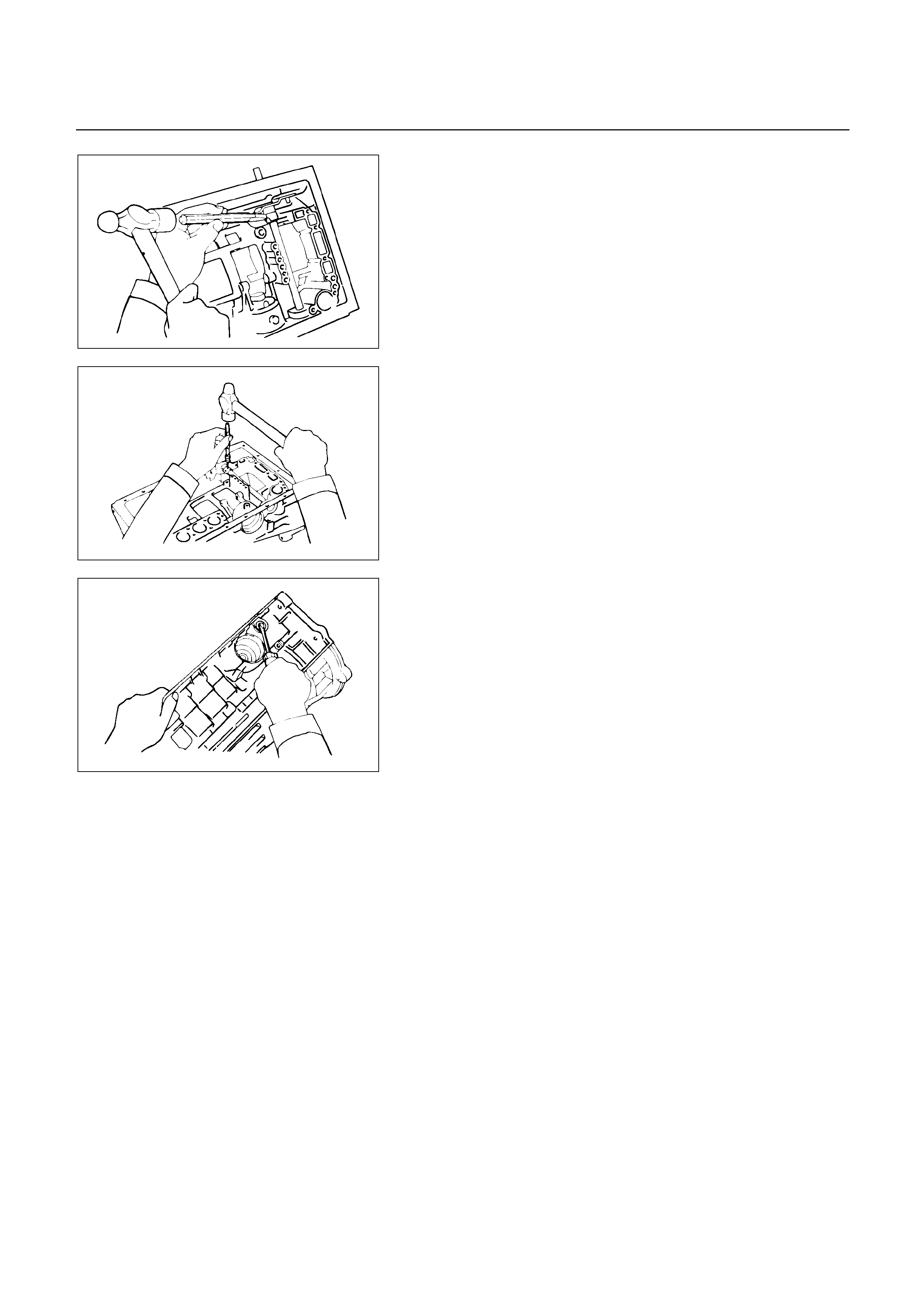
249RY00002
Disassembly steps
1. Spacer
Using a chisel, cut off the spacer and remove it from the
shaft.
249RY00003
2. Pin
Using a punch, drive out the pin.
3. Manual valve lever shaft
4. Manual valve lever
Pull the manual valve lever shaft out through the case
by the threads.
249RY00004
5. Oil seal
6. Oil seal
Using a screwdriver, remove the oil seal.
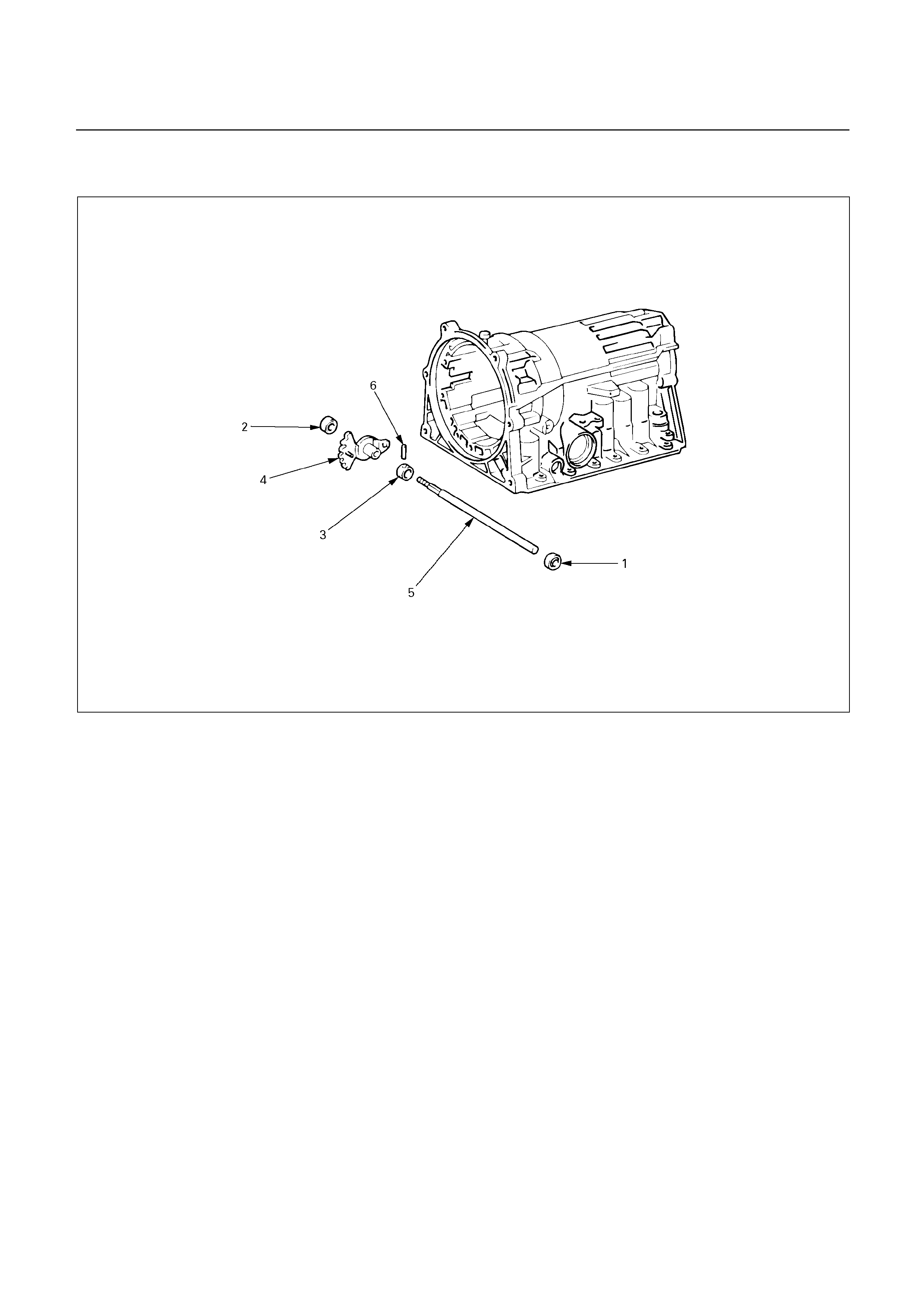
REASSEMBLY
249RX00001
Reassembly steps
1. Oil seal
2. Oil seal
3. Spacer
4. Manual valve lever
5. Manual valve lever shaft
6. Pin
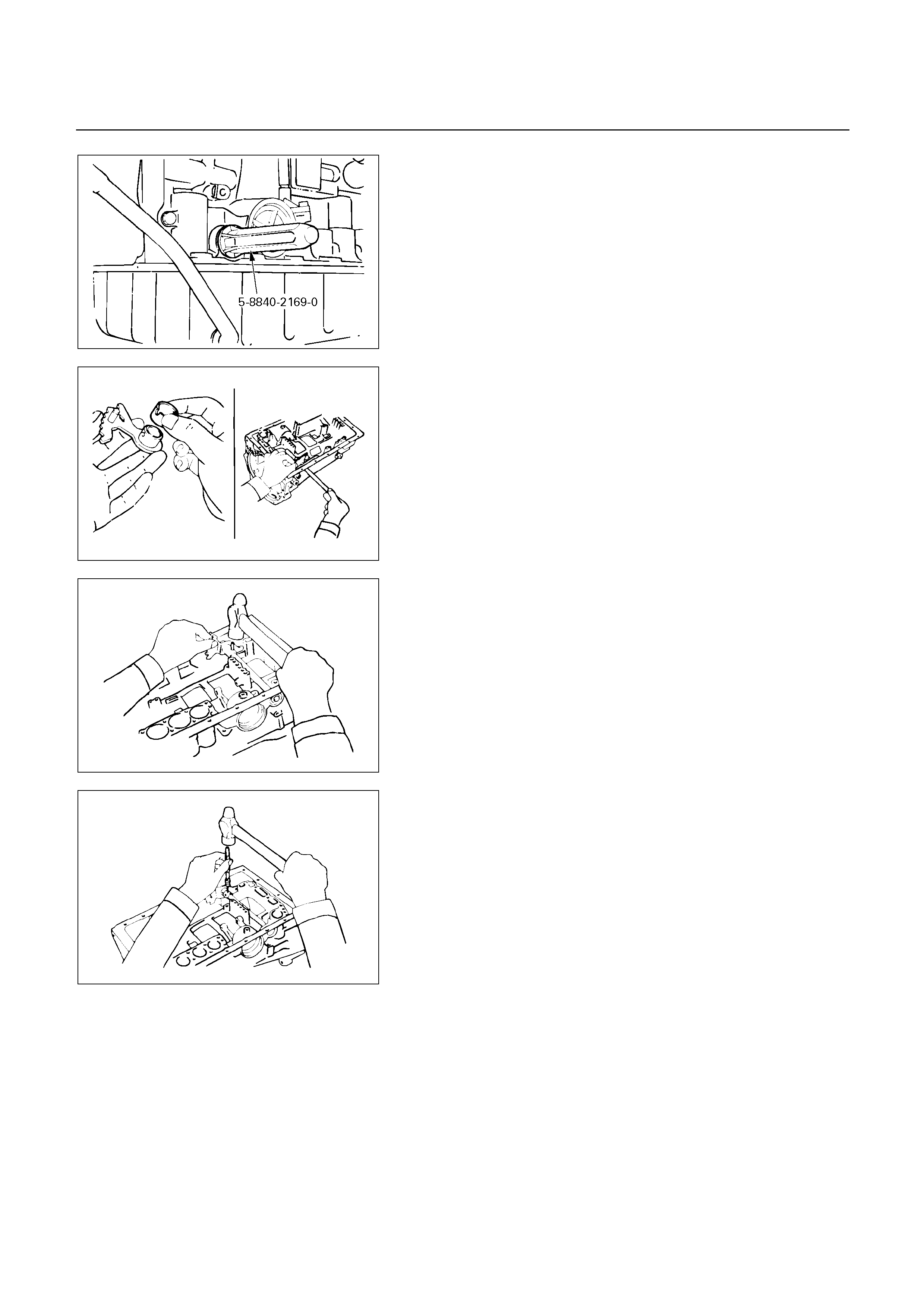
240RY00021
Reassembly steps
1. Oil seal
2. Oil seal
Coat a new oil seal lip with multi purpose grease.
Using special tool, drive in the oil seal.
Oil seal installer : 5-8840-2169-0 (J-37232-2)
249RY00005
3. Spacer
4. Manual valve lever
Assemble a new spacer to the manual valve lever.
5. Manual valve lever shaft
Install the manual valve lever shaft to the transmission
case through the manual valve lever by the threads.
249RY00006
6. Pin
Drive in the pin with the slot at a right angle to the shaft.
249RY00003
Match the spacer hole to the lever staking hollow and
stake the spacer to the lever.
Make sure the manual valve lever shaft turns smoothly.

241RY00018
TORQUE CONVERTER
INSPECTION AND REPAIR
Insert special tool in end of torque converter.
Insert a turning tool into the inner race of the one-wa
y
clutch.
One-way clutch testing tool : 5-8840-2168-0
(J-35467)
Insert the stopper so that it fits in the notch of the
converter hub and outer race of the one-way clutch.
One-way clutch test
The clutch should lock when turned counterclockwise,
and rotate freely and smoothly clockwise. Less than 25
kg cm (22 Ib in) of torque should be required to rotate
the clutch clockwise. If necessary, clean the converte
r
and retest the clutch. Replace the converter if the clutch
still fails the test.
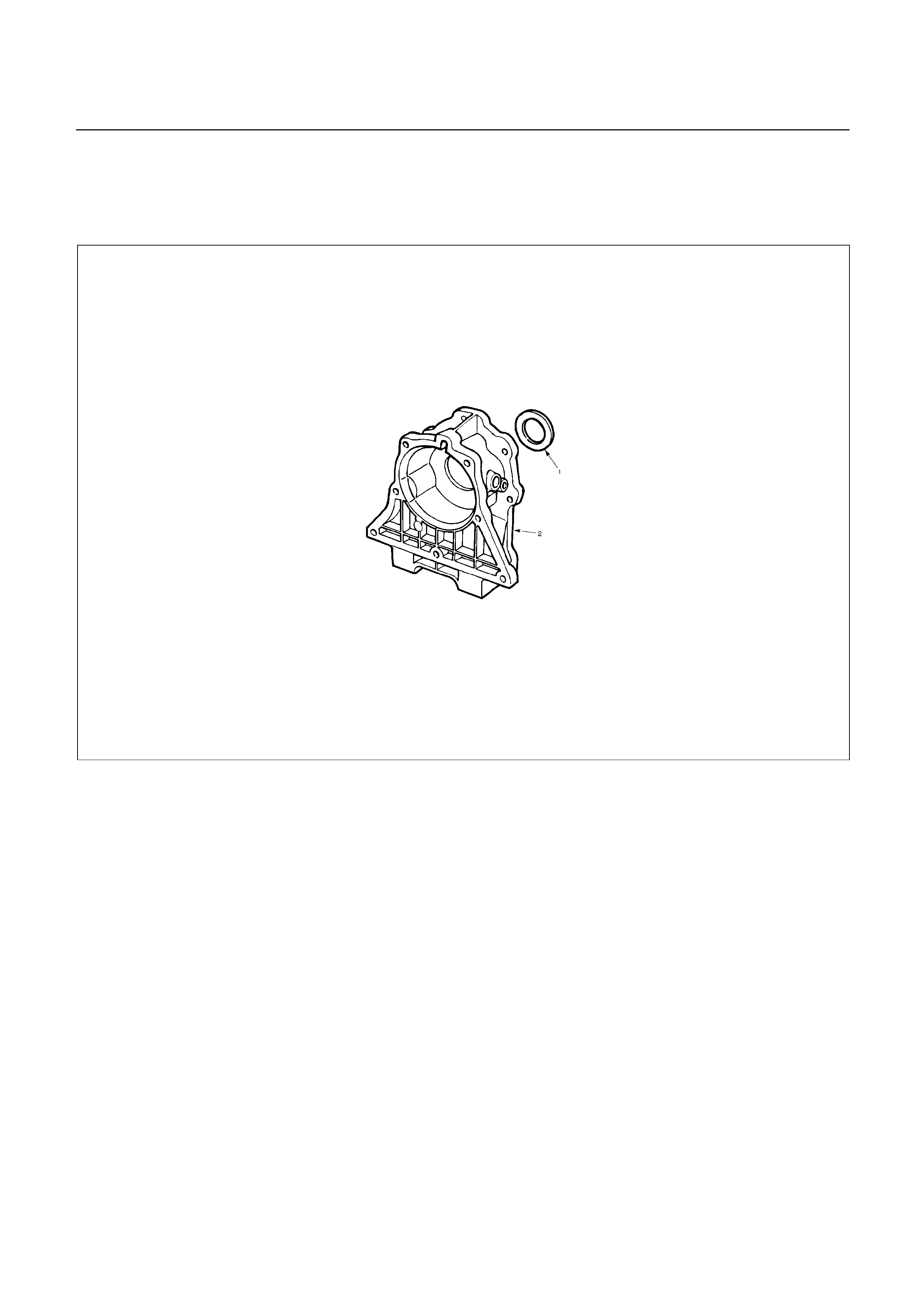
ADAPTER HOUSING (44)
DISASSEMBLY
241R200005
Disassembly steps
1. Oil seal
2. Adapter housing
Disassembly steps
1. Oil seal
2. Adapter housing
Using a screwdriver, remove the oil seal.
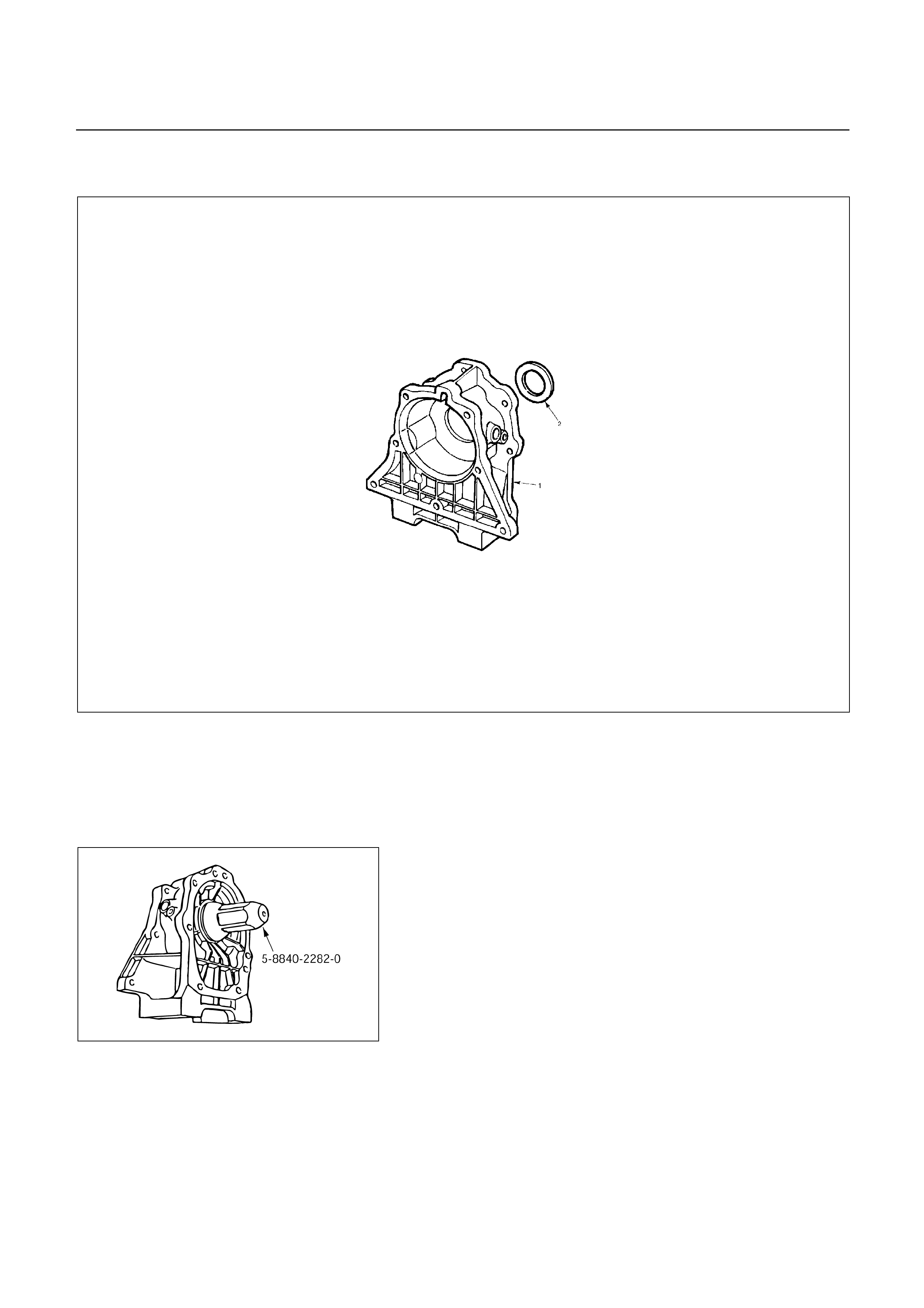
REASSEMBLY
241R200006
Reassembly steps
1. Adapter housing
2. Oil seal
240RY00003
Reassembly steps
1. Adapter housing
2. Oil seal
Using oil seal installer, install the new oil seal to the
adapter housing.
Oil seal installer : 5-8840-2282-0
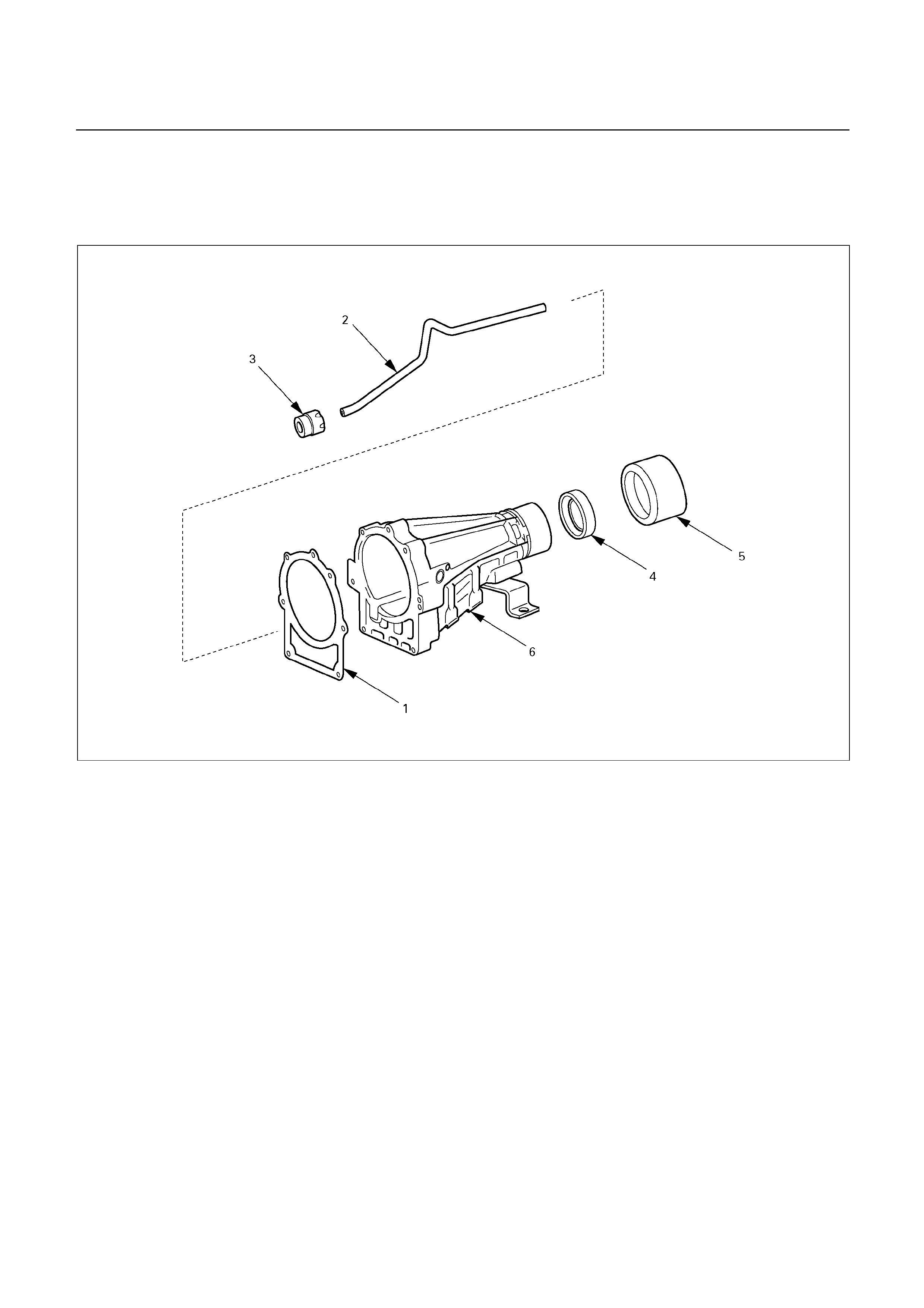
EXTENSION HOUSING (42)
DISASSEMBLY
241R200007
Disassembly steps
1. Gasket
2. Tube
3. Tube packing
4. Oil seal
5. Dust deflector
6. Extension housing
Disassembly steps
1. Gasket
2. Tube
3. Tube packing
4. Oil seal
Using a screwdriver, remove the oil seal.
NOTE:
The oil seal can be removed without removing the
dust deflector.
5. Dust deflector
6. Extension housing
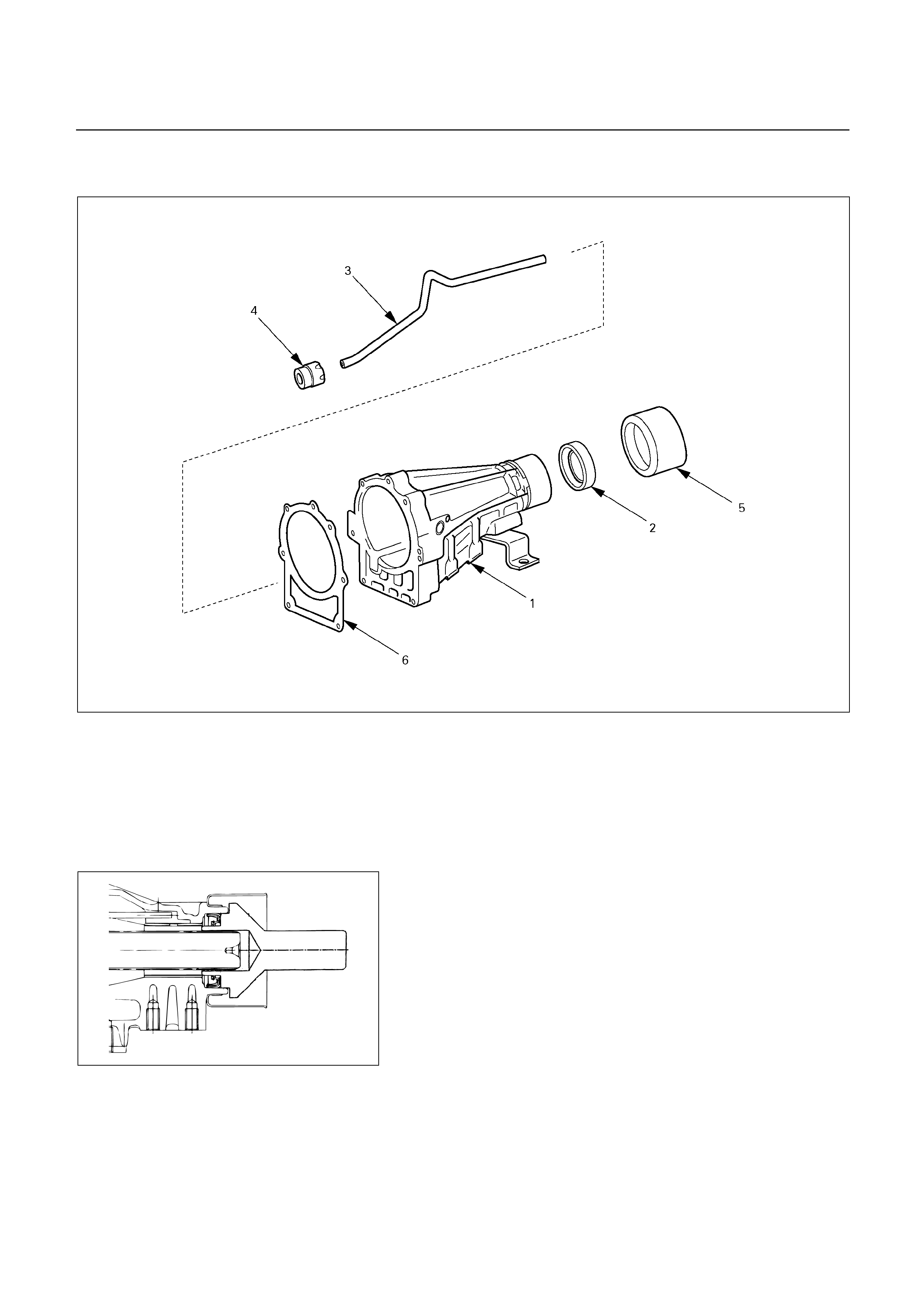
REASSEMBLY
241R200008
Reassembly steps
1. Extension housing
2. Oil seal
3. Tube
4. Tube packing
5. Dust deflector
6. Gasket
249L100005
Reassembly steps
1. Extension housing
2. Oil seal
Using oil seal installer, install the new oil seal to the
extension housing.
Oil seal installer : 5-8840-2702-0
NOTE:
The oil seal can be installed without removing the
dust deflector.
3. Tube
4. Tube packing
5. Dust deflector
6. Gasket
MAIN DATA AND SPECIFICATIONS
GENERAL SPECIFICATIONS
Remaks
Model AW30-40LE
Engine
’02 UBS 4JX1-TC
’02 TFR/S 4JH1-TC
Electronic control, planetary gear type
Type 3-element 1-stage 2-phase type
(with lock-up mechanism)
1st 2.804
2nd 1.532
3rd 1.000
4th (O/D) 0.705
Gear ratio
Reverse 2.394
Name
ATF DEXRON III
Oil used Q’ty (l) UBS and TFR/S 8.7
Torque converter
UBS 2450150
TFR/S ???? 150
Stall speed (rpm)
Forward clutch C-1 UBS 6, TFR/S 5
Direct clutch C-2 UBS 5, TFR/S 4
OD direct clutch C-0 2
Number of discs
Second coast brake B-1 40 mm Band width or
Number of discs
Second brake B-2 5
First and reverse brake B-3 UBS 7, TFR/S 6
Friction element
Overdrive brake B-0 4
Number of discs
One-way clutch No.1 F-1 22
One-way clutch No.2 F-2 28
Clutch
OD one-way clutch F-0 24
Number of sprage
Sun gear 42
Pinion gear 19
Front planetary
Ring gear 79
Sun gear 33
Pinion gear 23
Rear planetary
Ring gear 79
Sun gear 33
Pinion gear 23
Planetary gear
O/D planetary
Ring gear 79
Number of teeth
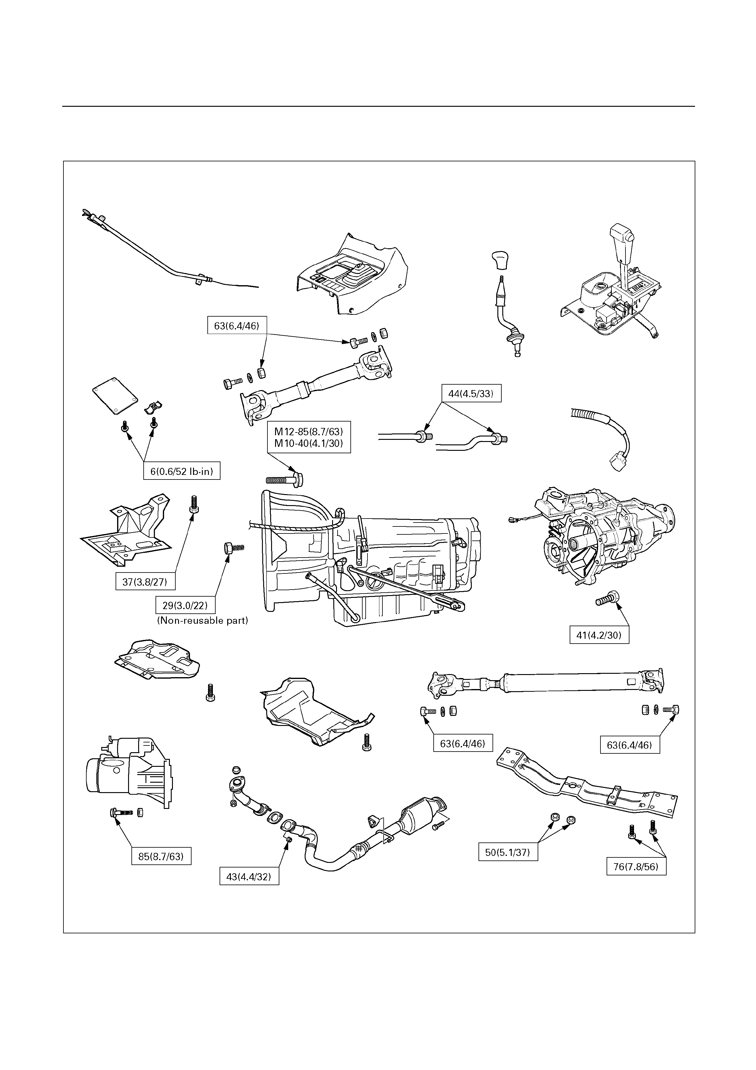
TORQUE SPECIFICATIONS
UBS N m (kg m/Ib ft)
E07R200015
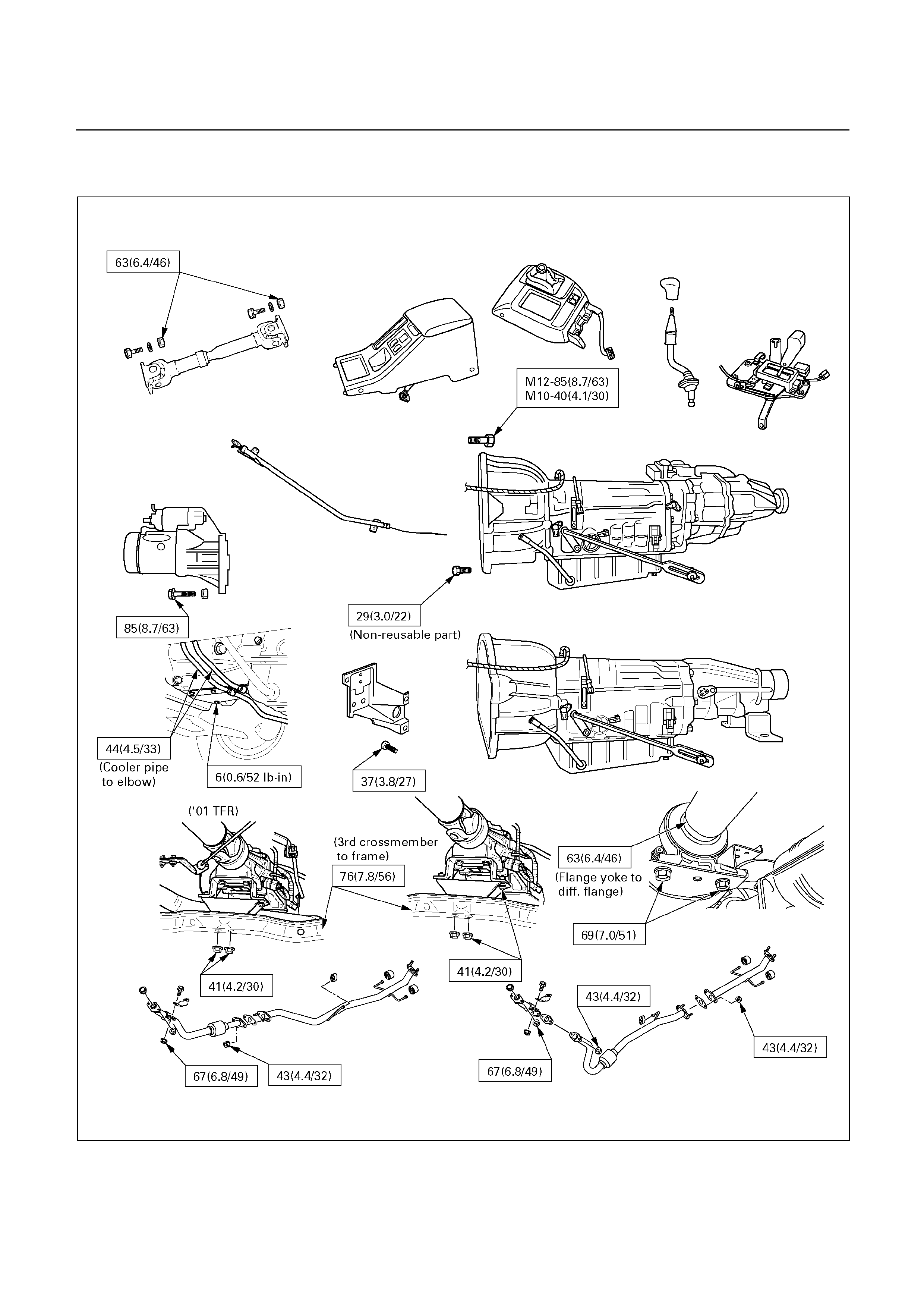
TFR/S N m (kg m/Ib ft)
E07L200005
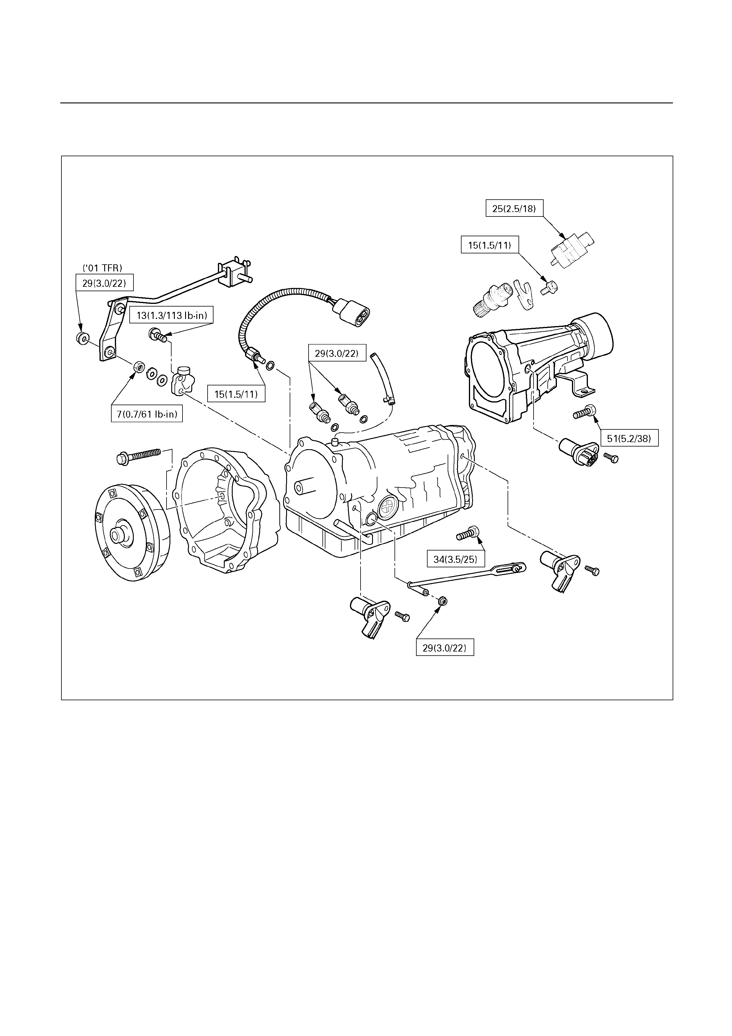
Nm (kg m/Ib ft)
E07R200016
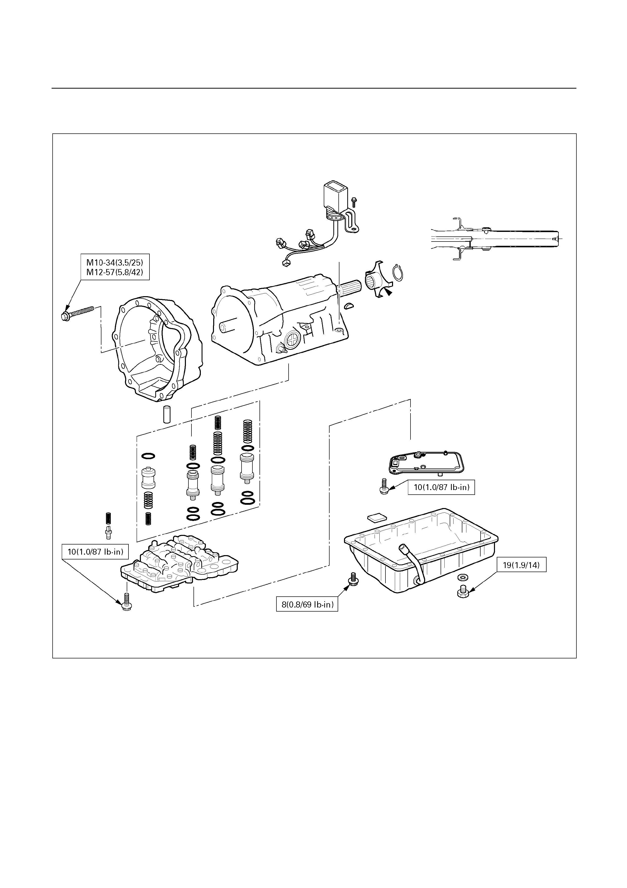
Nm (kg m/Ib ft)
E07R200017
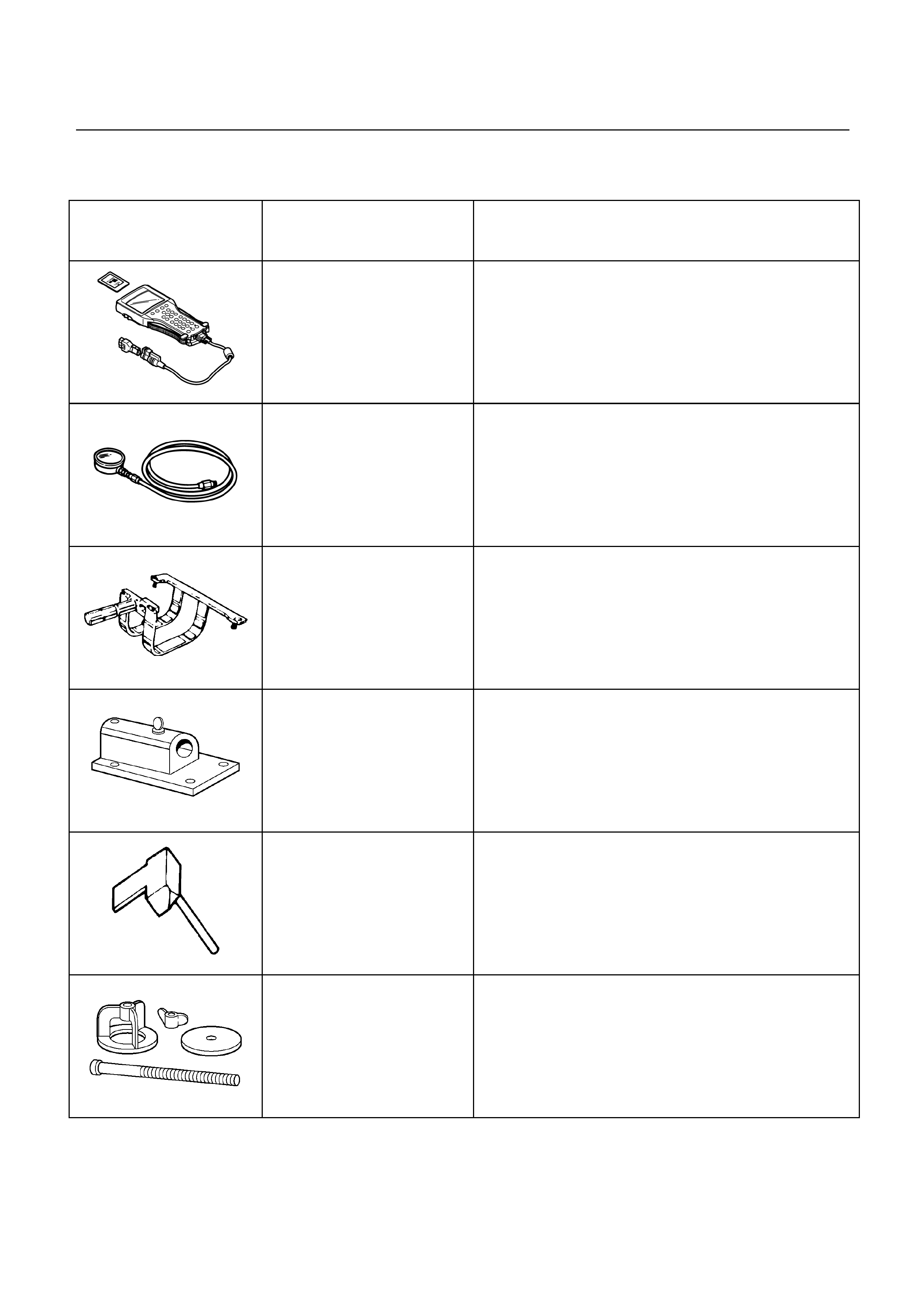
SPECIAL TOOLS
ILLUSTRATION PART NO. PART NAME
Tech 2 scan tool
5884000930
5-8840-0093-0 Oil pressure gauge
901RY00018
5-8840-2152-0
(J-37227) Holding fixture
901RT096
5-8840-0003-0
(J-2389-20) Holding fixture base
901RY00019
5-8840-2153-0
(J-37228) Oil pan seal cutter
901RY00028
5-8840-0195-0
(J-23327-1) Spring compressor
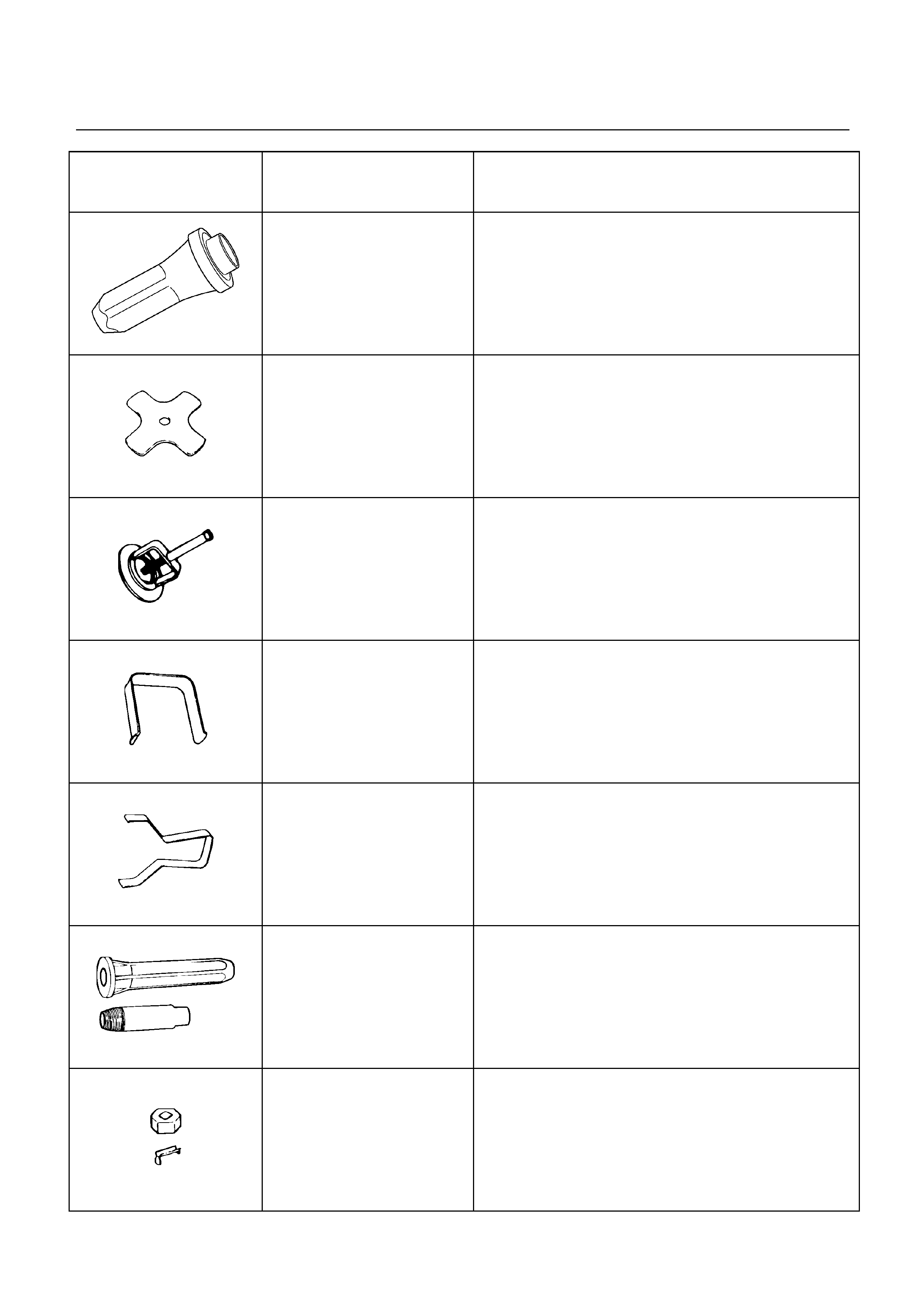
ILLUSTRATION PART NO. PART NAME
901RY00020
5-8840-2256-0
(J-9617) Oil seal installer; oil pump
901RY00021
5-8840-2170-0
(J-37233) OD brake piston spring compressor
901RY00022
5-8840-0254-0
(J-25048) Spring compressor (snap ring)
901RY00023
5-8840-2173-0
(J-37236) 1st/reverse brake puller
901RY00024
5-8840-2174-0
(J-37237) 1st/reverse brake puller
901RY00025
5-8840-2169-0
(J-37232-2) Manual valve shaft seal installer & remover
901RY00026
5-8840-2168-0
(J-35467)
One-way clutch testing tool;
torque converter
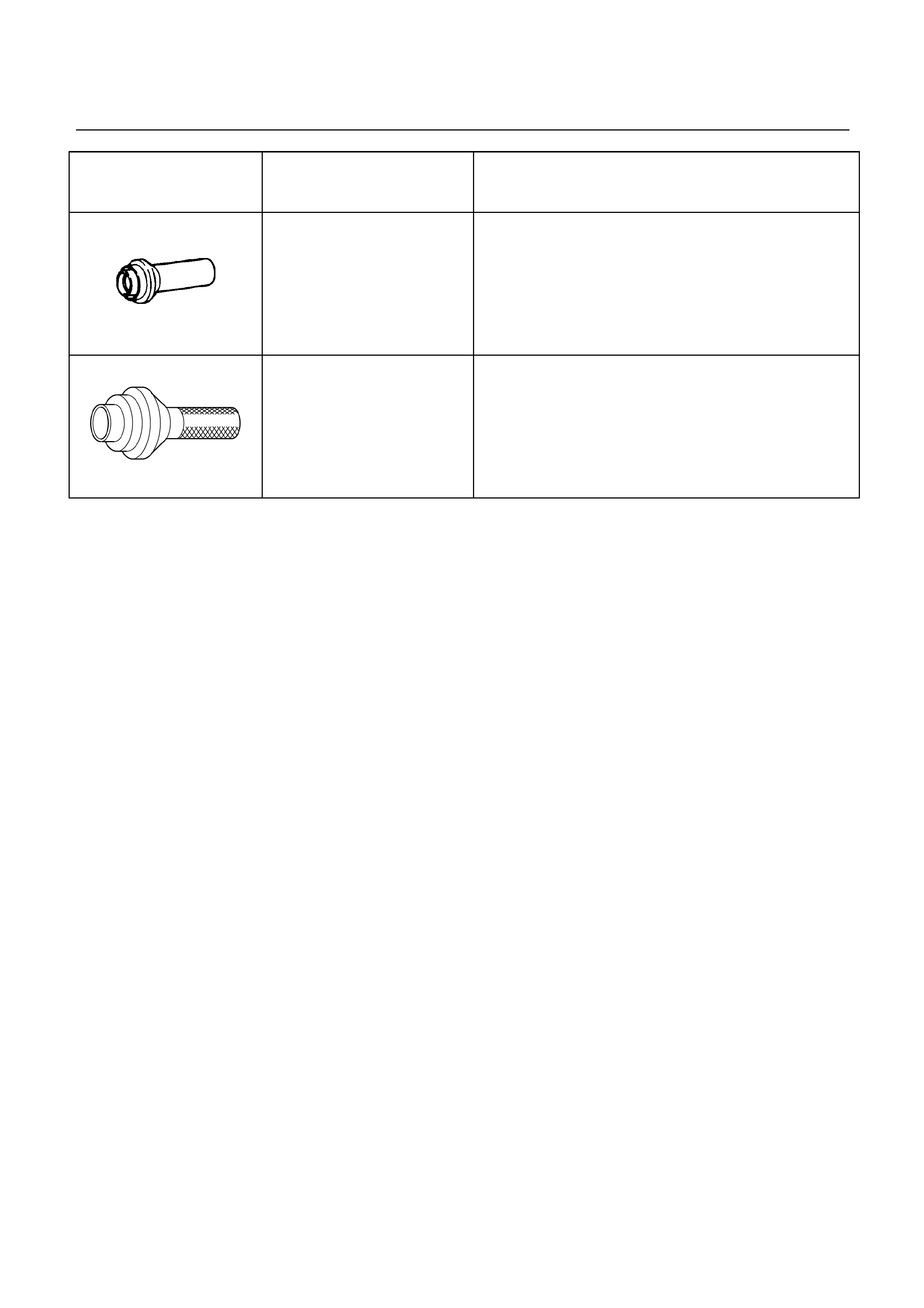
ILLUSTRATION PART NO. PART NAME
901RY00027
5-8840-2282-0 Oil seal installer;
adapter housing (4 4)
5884027020
5-8840-2702-0 Oil seal installer;
extension housing (4 2)