
SECTION 7E - TRANSFER CASE (TOD)
Service Precaution
Transfer Case Assembly
Removal
Transfer Rear Oil Seal
Transfer Rear Oil Seal and Associated Parts
Removal
Installation
TOD ECU
Removal
Installation
Unit Repair
Inspection
Transfer Case
Disassembled View
Disassembly
Reassembly
Transfer Cover Assembly
Disassembled View
Disassembly
Reassembly
Transfer Case Assembly Clutch Pack and Clutch Cam
Disassembled View
Disassembly
Sprocket and Mechanical Lock
Disassembled View
Disassembly
Output Shafts and Shift Control Shaft
Disassembled View
Disassembly
Transfer Case
Disassembled View
Disassembly
Inspection and Repair
Transfer Case
Disassembled View
Reassembly
Output Shafts and Shift Control Shaft
Disassembled View
Reassembly
Sprocket and Mechanical Lock
Disassembled View
Reassembly
Clutch Pack and Clutch Cam
Disassembled View
Reassembly
Main Data and Specifications
Special Tools
Service Precaution
WARNING: IF SO EQUIPPED WITH A
SUPPLEMENTAL RESTRAINT SYSTEM (SRS),
REFER TO THE SRS COMPONENT AND WIRING
LOCATION VIEW IN ORDER TO DETERMINE
WHETHER YOU ARE PERFORMING SERVICE ON
OR NEAR THE SRS COMPONENTS OR THE SRS
WIRING. WHEN YOU ARE PERFORMING SERVICE
ON OR NEAR THE SRS COMPONENTS OR THE SRS
WIRING, REFER TO THE SRS SERVICE
INFORMATION. FAILURE TO FOLLOW WARNINGS
COULD RESULT IN POSSIBLE AIR BAG
DEPLOYMENT, PERSONAL INJURY, OR
OTHERWISE UNNEEDED SRS SYSTEM REPAIRS.
CAUTION: Always use the correct fastener in the
proper location. When you replace a fastener, use
ONLY the exact part number for that application.
HOLDEN will call out those fasteners that require a
replacement after removal. HOLDEN will also call
out the fasteners that require thread lockers or
thread sealant. UNLESS OTHERWISE SPECIFIED,
do not use supplemental coatings (Paints, greases,
or other corrosion inhibitors) on threaded fasteners
or fastener joint interfaces. Generally, such
coatings adversely affect the fastener torque and
the joint clamping force, and may damage the
fastener. When you install fasteners, use the correct
tightening sequence and specifications. Following
these instructions can help you avoid damage to
parts and systems.
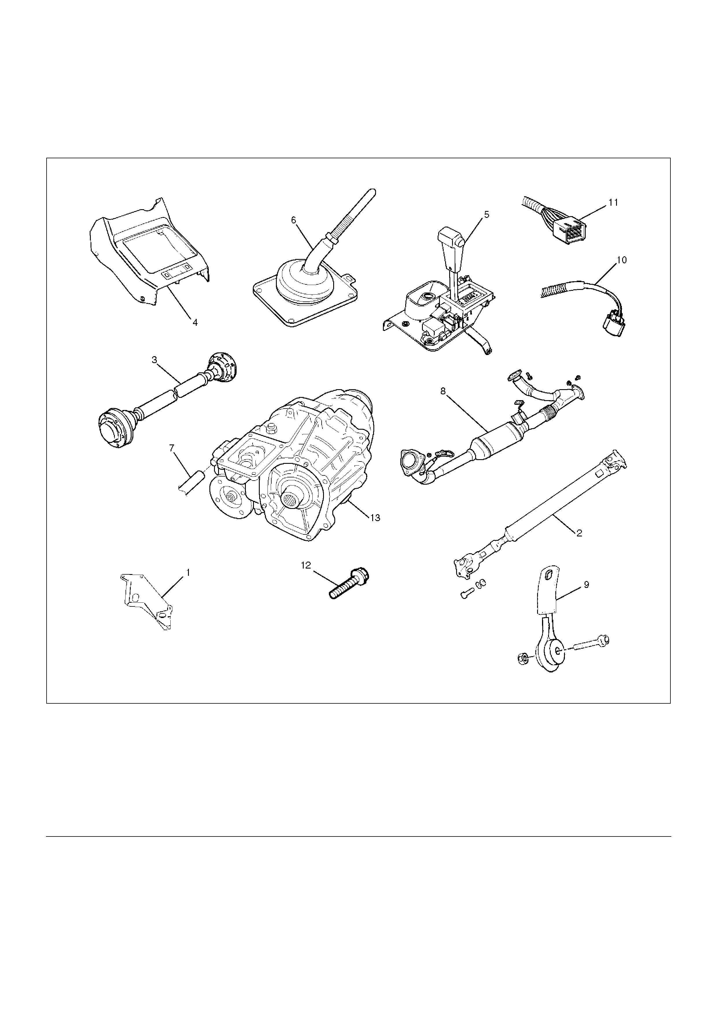
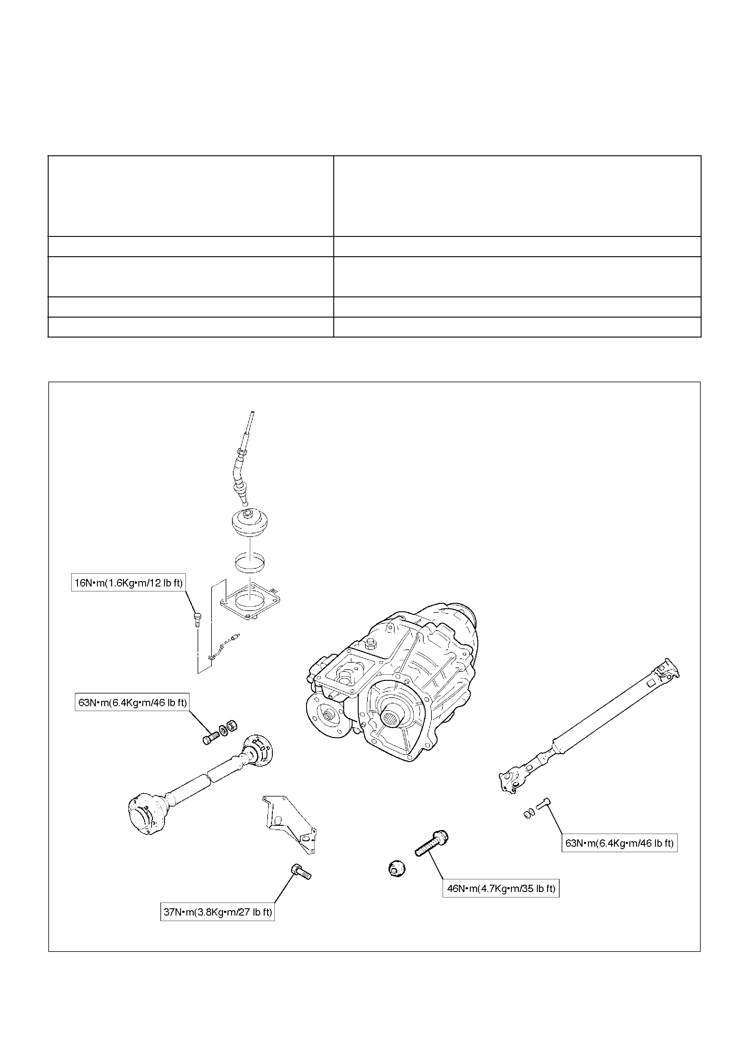
Transfer Case Assembly
Removal
F07RW083
EndOFCallout
1. Disconnect the ground cable.
2. Remove the transfer protector.
3. Remove the rear propeller shaft from the transfer
case.
4. Remove the front propeller shaft from the transfer
case.
5. Remove the shift control rod from the selector lever
assembly.
6. Disconnect the wiring harness connector, transfer
control lever knob and shift lock cable and then
remove the front console.
7. Remove the selector lever assembly and put it
aside.
Legend
(1) Transfer Protector
(2) Rear Propeller Shaft
(3) Front Propeller Shaft
(4) Front Console
(5) Selector Lever Assembly
(6) Transfer Control Lever
(7) Breather Hose
(8) Exhaust Pipe
(9) Seat Belt Tension Rod
(10) Speed Sensor Harness Connector
(11) Transfer Harness Connector
(12) Transfer Case Bolt
(13) Transfer Case
8. Remove the transfer control lever.
9. Disconnect the breather hose.
10. Remove the left front exhaust pipe fixing bolts and
nuts, and put the exhaust pipe aside.
11. Remove the left seat belt tension rod and put the
rear proper shaft aside.
260RW006
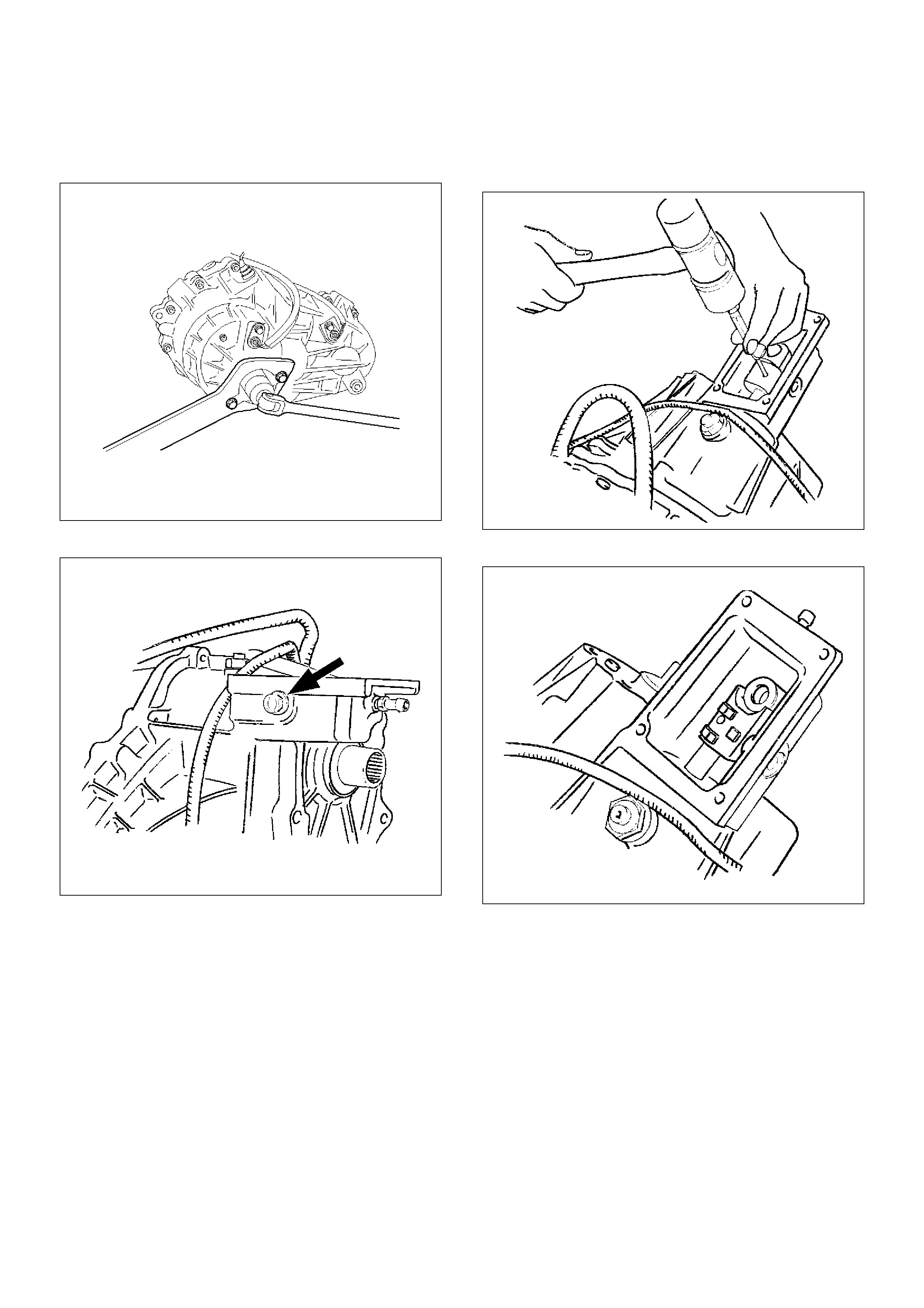
12. Disconnect the transfer harness connector from the
top of the transfer case.
13. Disconnect the speed sensor harness connector.
14. Remove the fuel pipe clip fixing bolt on the transfer
case.
15. Support the transmission with a jack.
16. Remove the seven bolts from the transfer case.
17. Remove the transfer case assembly.
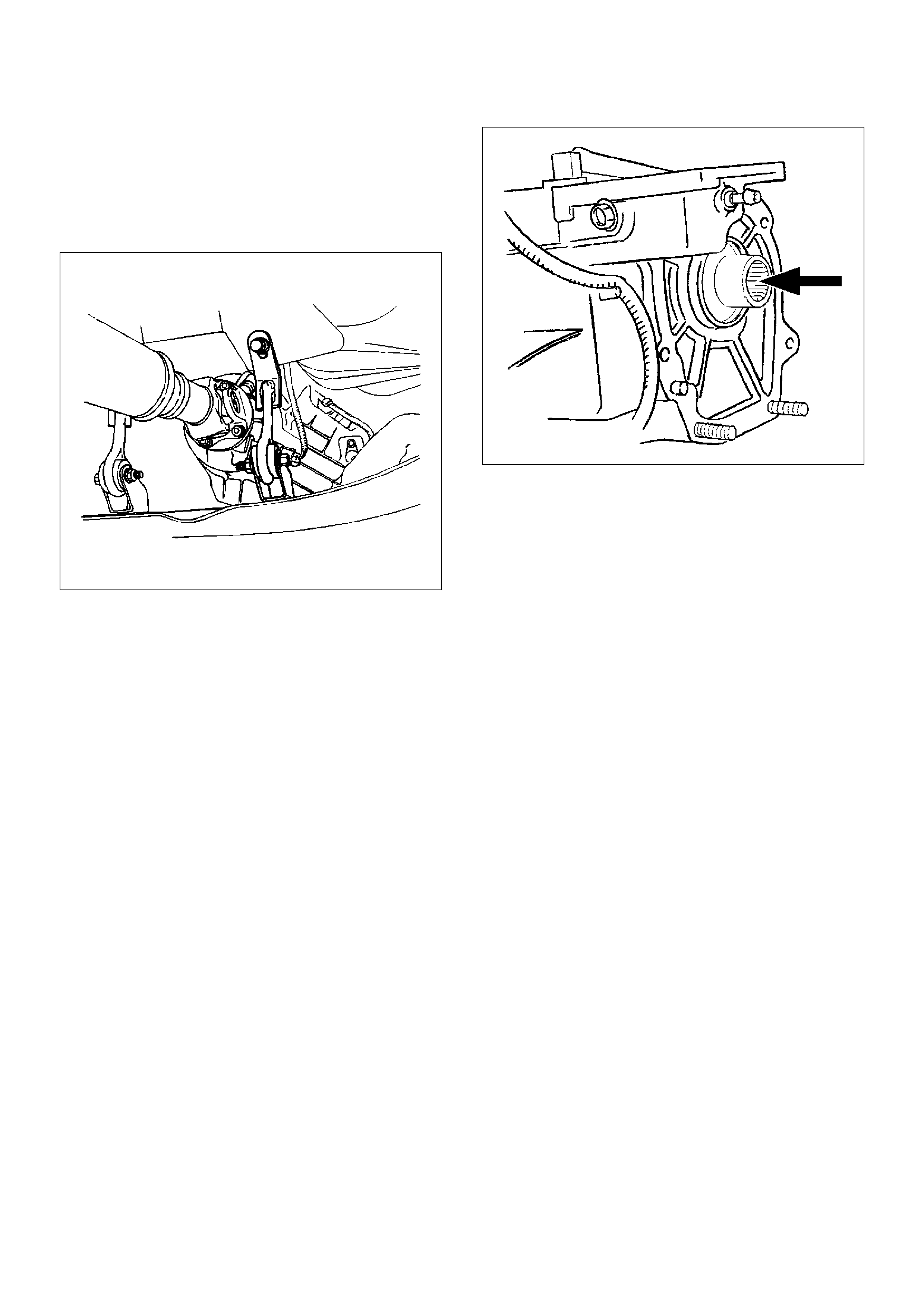
Installation
To install, follow the removal steps in the reverse order,
noting the following points:
1. Apply a thin coat of grease (Besco L2) or equivalent
to the input shaft spline.
261RW024
2. Mount the transfer case.
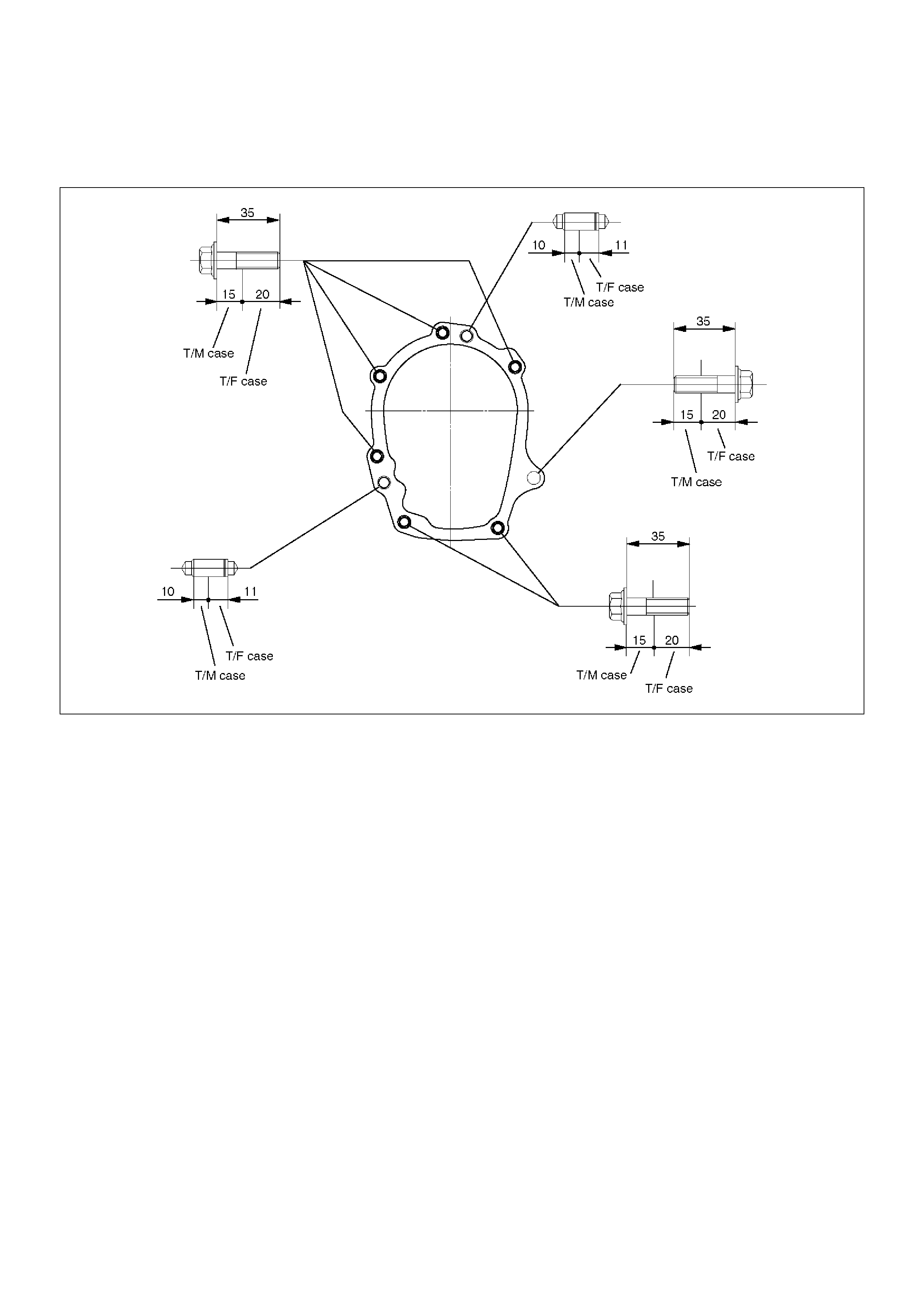
3. Tighten the transfer case bolts (see the figure
below).
Torque : 46 N·m (4.7kg·m/34lbft)
261RW004-1
4. Tighten the propeller shaft bolts.
Torque : 63 N·m (6.4kg·m/46lbft)
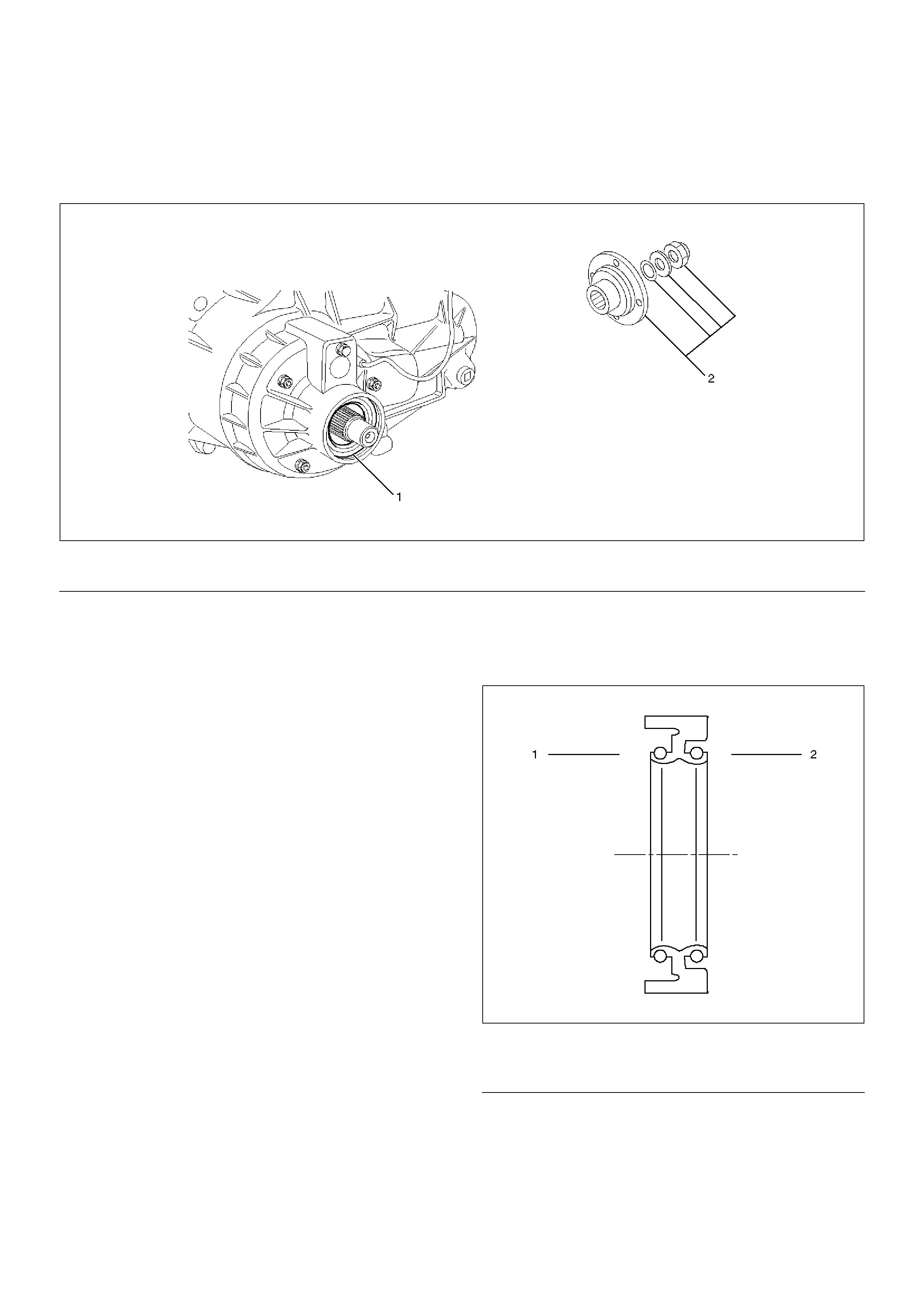
Transfer Rear Oil Seal
Transfer Rear Oil Seal and Associated Parts
261RW005
EndOFCallout
Removal
1. Remove the rear propeller shaft from the transfer
case.
2. Using the flange holder 5-8840-0133-0 (J-8614-11),
remove the end nut.
3. Using the universal puller, remove the rear
companion flange, washer and O-ring.
4. Remove the oil seal from the transfer rear case.
Installation
1. Apply engine oil to the oil seal outer surfaces. Fill
the oil seal lip with grease (Besco L2).
261RW006
EndOFCallout
Legend
(1) Oil Seal (2) End Nut and Rear Companion Flange
Legend
(1) Inside
(2) Outside
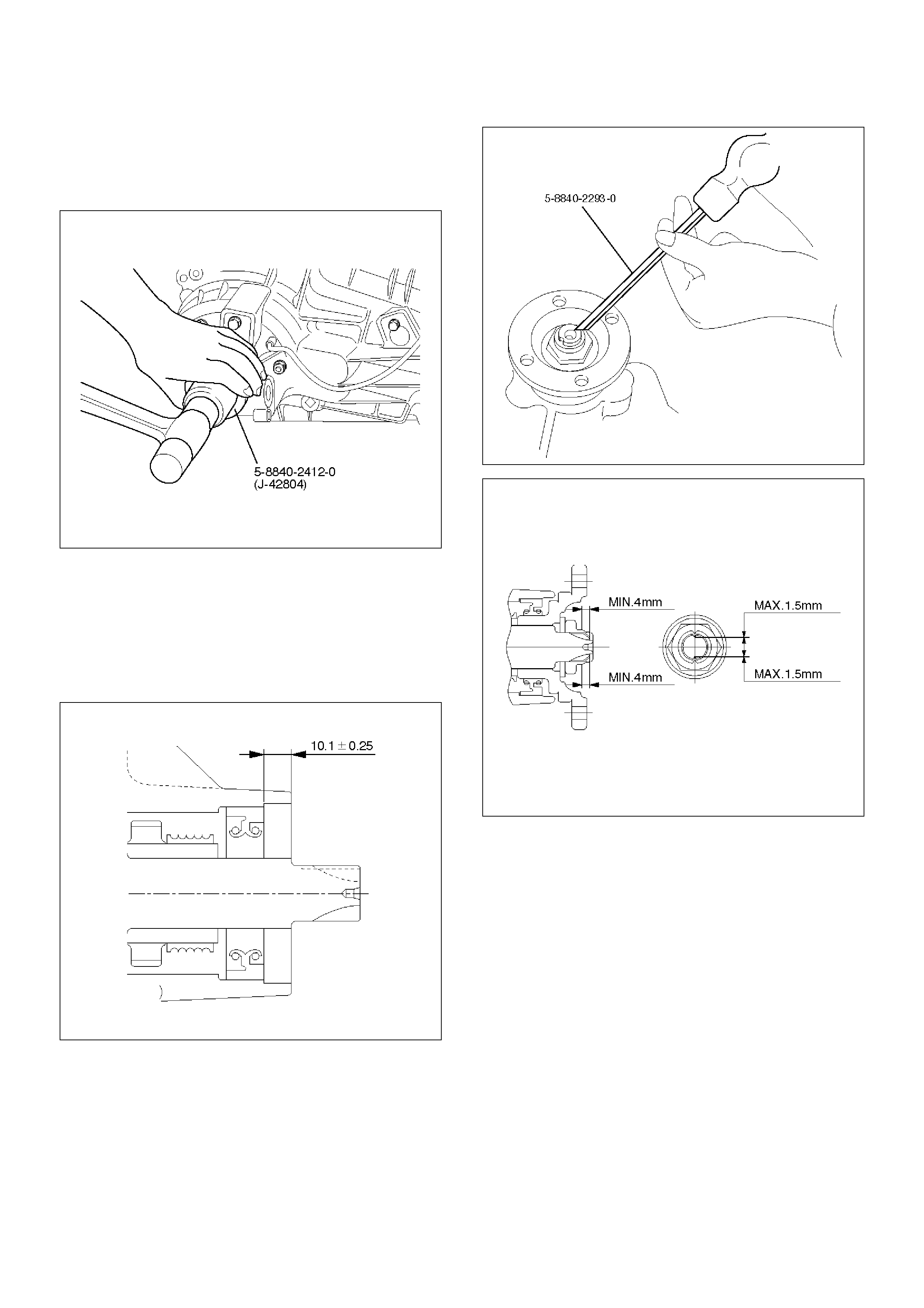
2. Using the oil seal installer 5-8840-2412-0 (J-42804),
install the oil seal.
NOTE: When installing the oil seal, pay attention to the
direction.
261RW051
Rear Output Shaft Oil Seal
Distance between the transfer case end and oil seal.
NOTE: When installing the oil seal to the specified
dimension, be careful not to damage it.
Distance : 9.85—10.35mm(0.39—0.41in)
A04RW004
1. Mount the rear companion flange, O-ring , washer,
and nut to the transfer case in this order.
2. Using the flange holder 5-8840-0133-0 (J-8614-11),
install a new end nut.
Torque : 167 N·m (17kg·m/123lbft)
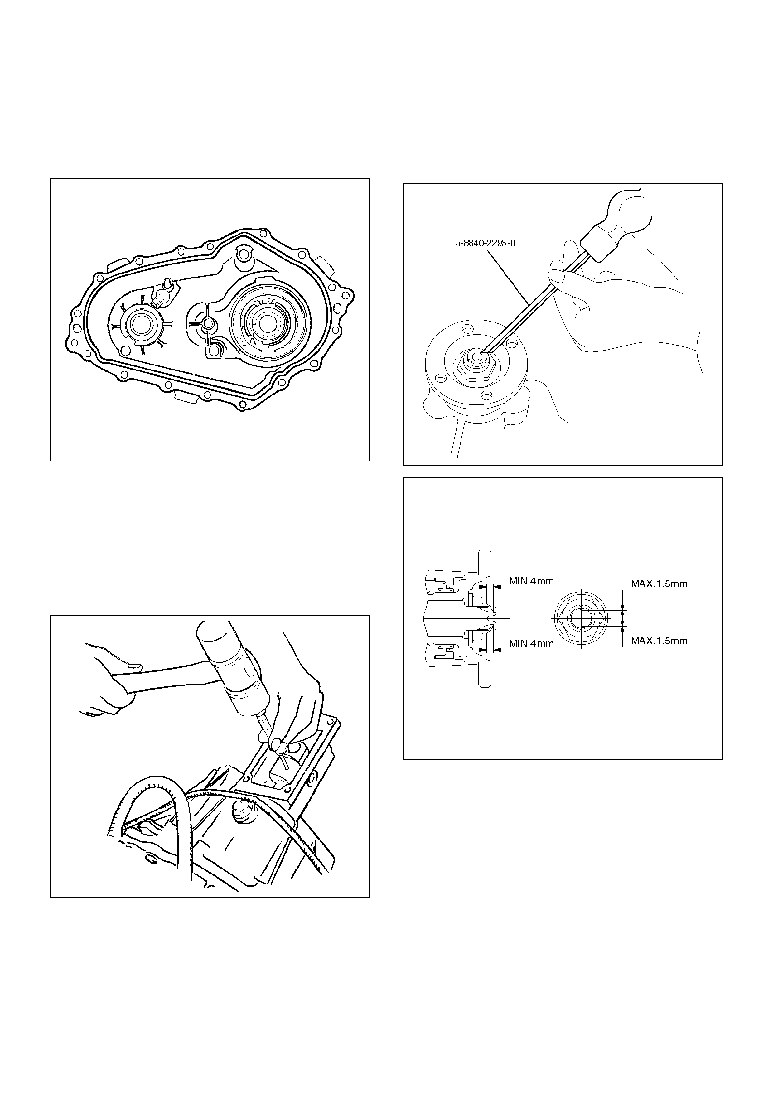
3. Using the punch 5-8840-2293-0 (J-39209), stake
the end nut at two spots.
NOTE: Check the staked end nut is free from cracks.
266RW028
260RW007
4. Install the rear propeller shaft to the transfer case
and tighten to the specified torque.
Torque : 63 N·m (6.4kg·m/46lbft)
TOD ECU
Removal
1. Disconnect the ground cable.
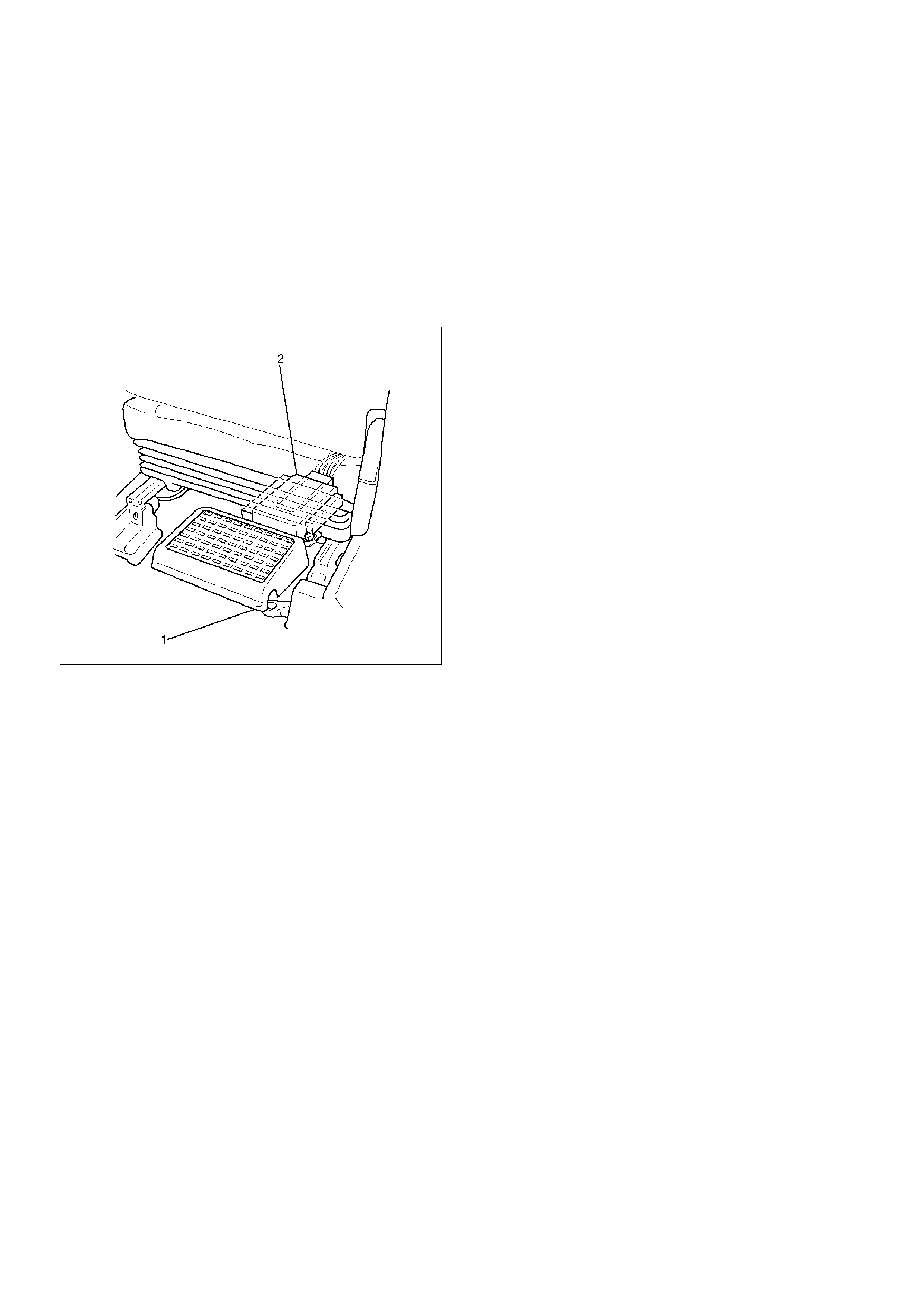
2. Move the right-hand seat forward and remove the
second seat foot rest (1).
3. Disconnect the connector from the ECU (2).
4. Remove the bolts and detach the ECU (2) from the
bracket.
F07RW021
Installation
1. Perform the removal step in reverse order.
Unit Repair
Inspection
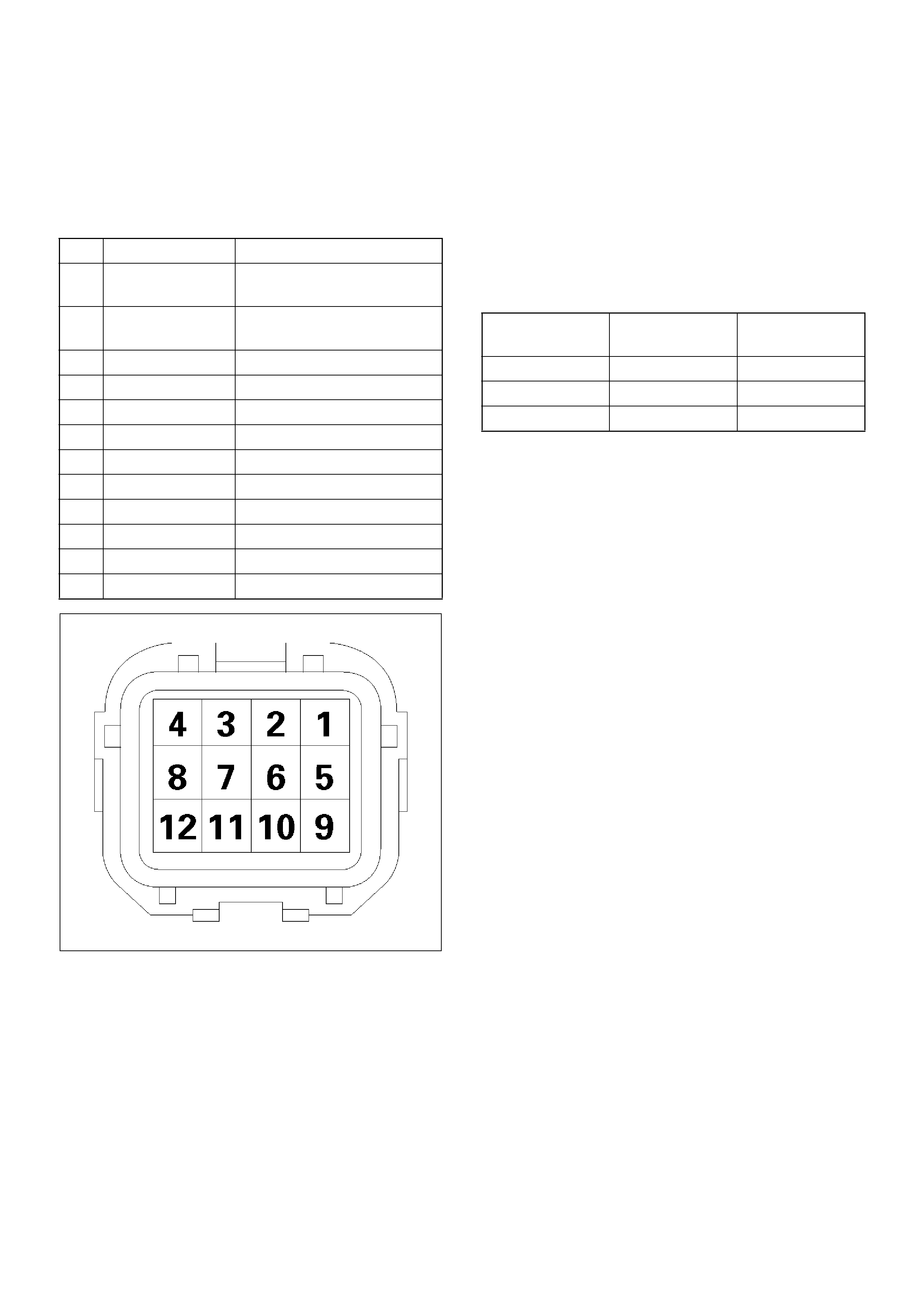
Before disassembling and after assembling, check the
following items on the transfer connector terminals.
810RW002
4H and 4L switch
Check whether the 4H switch (terminals 4 and 7) and 4L
switch (terminals 12 and 3 ) work as specified in the
table below. If yes, the continuity is established on
these switches. If not, check the switches, shift rails,
transfer case, and rear cover, and replace the failed
parts.
Power GND
Check that there is a continuity between the power GND
pin (terminal 7) and transfer case. If not, replace the
grounding wire.
Resistance of electromagnetic coil
Check the resistance between electromagnetic coil
(terminal 8) and power GND (terminal 7). If not,
replace the electromagnetic coil.
Standard : 1.4 ~ 2.0W
Allowable : 1.0 ~ 5.0W
No. NAME CONTENTS
1 Ref . (Rr . ) Rear speed sensor
reference output
2 Ref . (Frt . ) Front speed sensor
reference output
3 SW GND SW GND
4 4H SW (+) 4H SW plus terminal
5 Rer . (+) Rear speed sensor plus
6 Frt . (+) Front speed sensor plus
7 POWER GND Power GND
8 EMC (+) Electromagnetic coil
9 COM (–) (Rr .) Rear speed sensor GND
10 COM (–) (Frt .) Front speed sensor GND
11 NC Not used
12 4L SW (+) 4L SW plus terminal
SHIFT
POSITION
PIN4 (4to7)
4H SW
PIN12 (3to12)
4L SW
HIGH OFF OFF
(NEUTRAL) ON ON
4L OFF ON
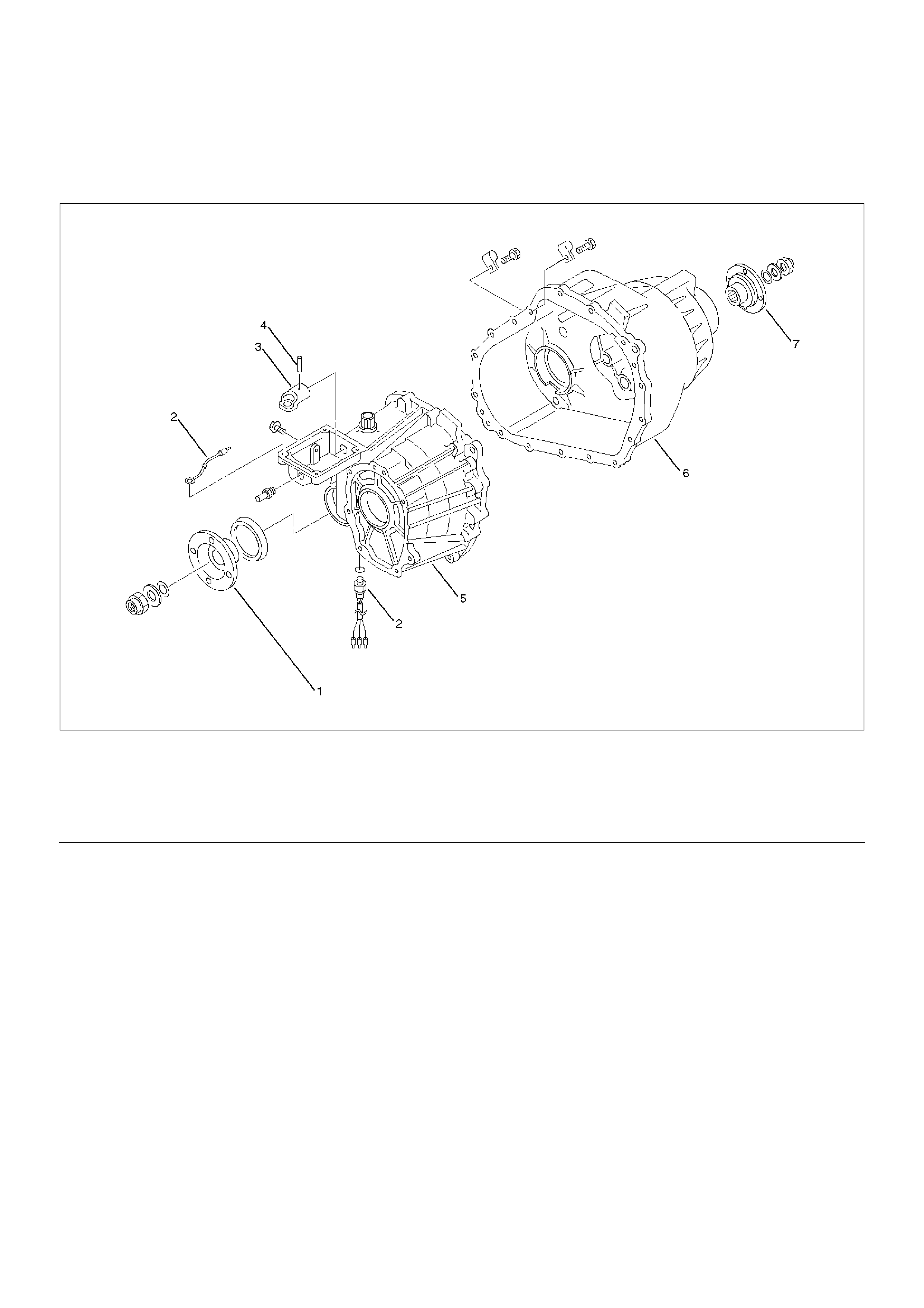
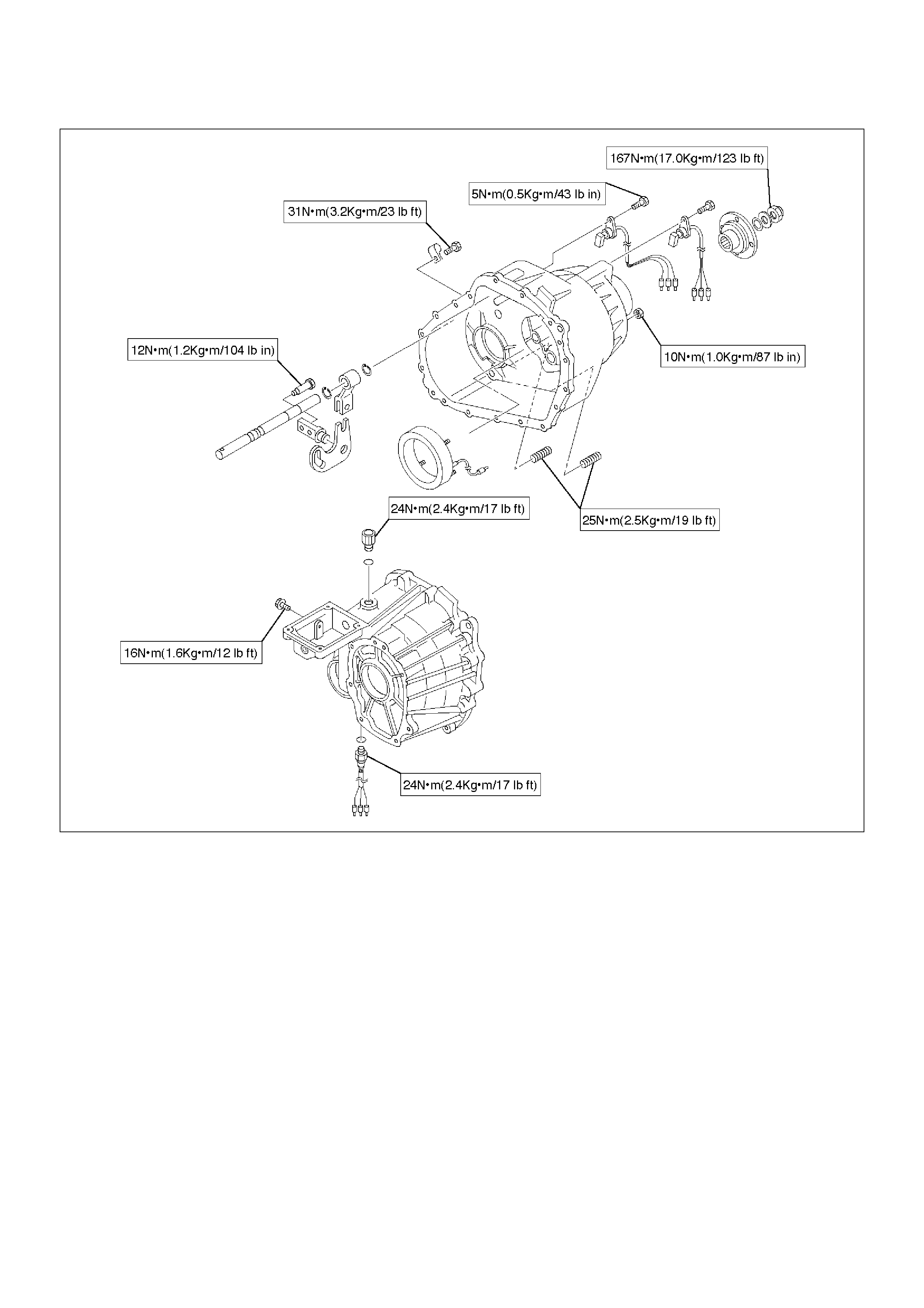
Transfer Case
Disassembled View
266RW004
EndOFCallout
Disassembly
1. Remove the drain plug from the transfer case and
drain the oil.
2. Disconnect the 4H and 4L switch and ground cable.
3. Remove the clip fixing the harness.
4. Using the flange holder 5-8840-0133-0 (J-8614-11),
remove the flange nut, and remove front companion
flange.
Legend
(1) Front Companion Flange
(2) 4H and 4L Switch, Ground Cable, and Center
Connector
(3) Offset Lever
(4) Spring Pin
(5) Transfer Case Assembly
(6) Transfer Cover Assembly
(7) Rear Companion Flange
5. Using the flange folder 5-8840-0133-0 (J-8614-11),
remove the flange nut, and remove rear companion
flange.
266RW005
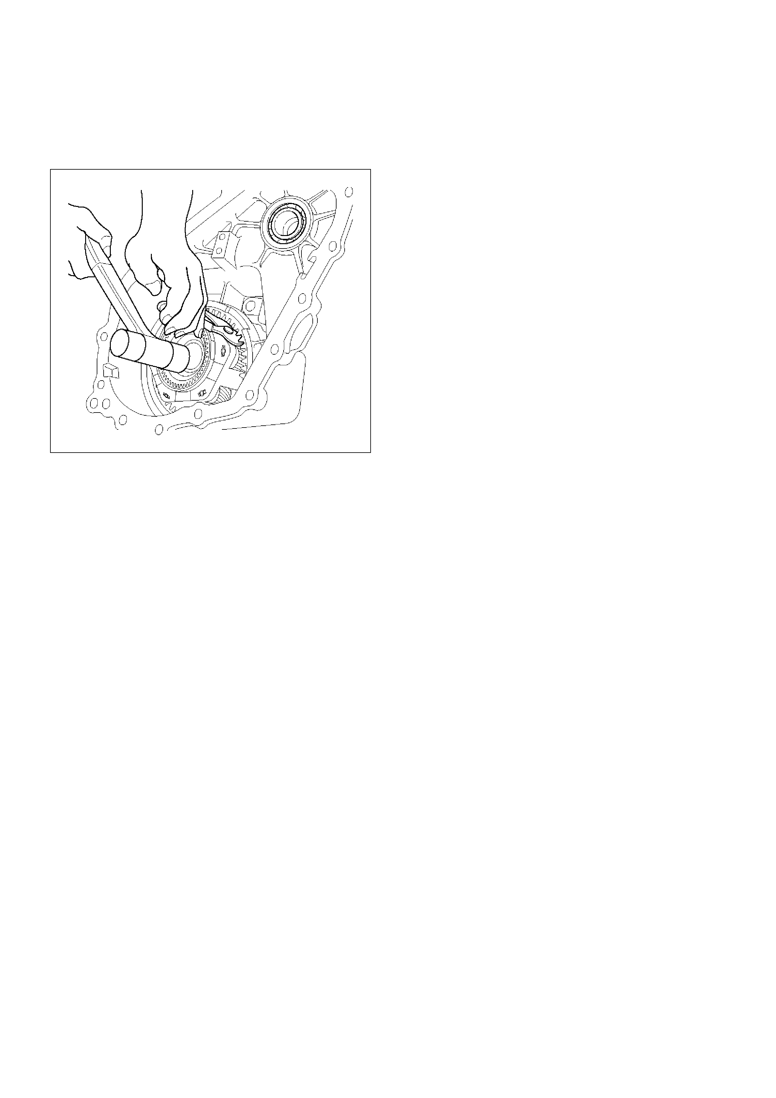
6. Remove the offset lever set bolt on the right side.
261RW015
7. Remove the offset lever lock spring pin.
NOTE: When removing the spring pin, note the recess
position of the pin.
261RW016
8. Remove the offset lever.
261RW017
9. Remove the sixteen bolts and detach the transfer
cover assembly from the transfer case assembly.
NOTE: When removing the transfer cover assembly, be
careful not to damage the oil seal.
Reassembly
1. Apply liquid gasket (Loctite 598 or equivalent)
uniformly to the mating face that contacts the
transfer case.
261RW023
2. Tighten the sixteen bolts to the specified torque.
Torque : 31 N·m (3.2kg·m/23lbft)
3. Wind the sealing tape around the drain plug thread
and tighten the plug to the specified torque.
Torque : 25 N·m (2.5kg·m/18lbft)
4. Mount the offset lever to the transfer shift and install
the spring pin.
261RW016
5. Attach the O-ring and washer to the companion
flange.
NOTE: Securely push the O-ring to the hollow of the
companion flange, and then attach the washer.
6. Use the flange holder 5-8840-0133-0 (J-8614-11) to
tighten the flange nut.
7. Tighten the flange nut to the specified torque.
Torque : 167 N·m (17.0kg·m/123 lbft)
8. Using the punch 5-8840-2293-0 (J-39209), securely
stake the flange nut at two spots.
NOTE: Check the staked flange nut is free from cracks.
266RW028
260RW007
9. Fix the harness with the clip.
10. Tighten the 4L and 4H switch to the specified
torque.
Torque : 24 N·m (2.4kg·m/17lbft)
11. Fill the transfer case with ATF II or III (1.9 liters).
12. Wind the sealing tape around the filler plug thread
and tighten the plug to the specified torque.
Torque : 25 N·m (2.5kg·m/18lbft)
Transfer Cover Assembly
Disassembled View
261RW007
EndOFCallout
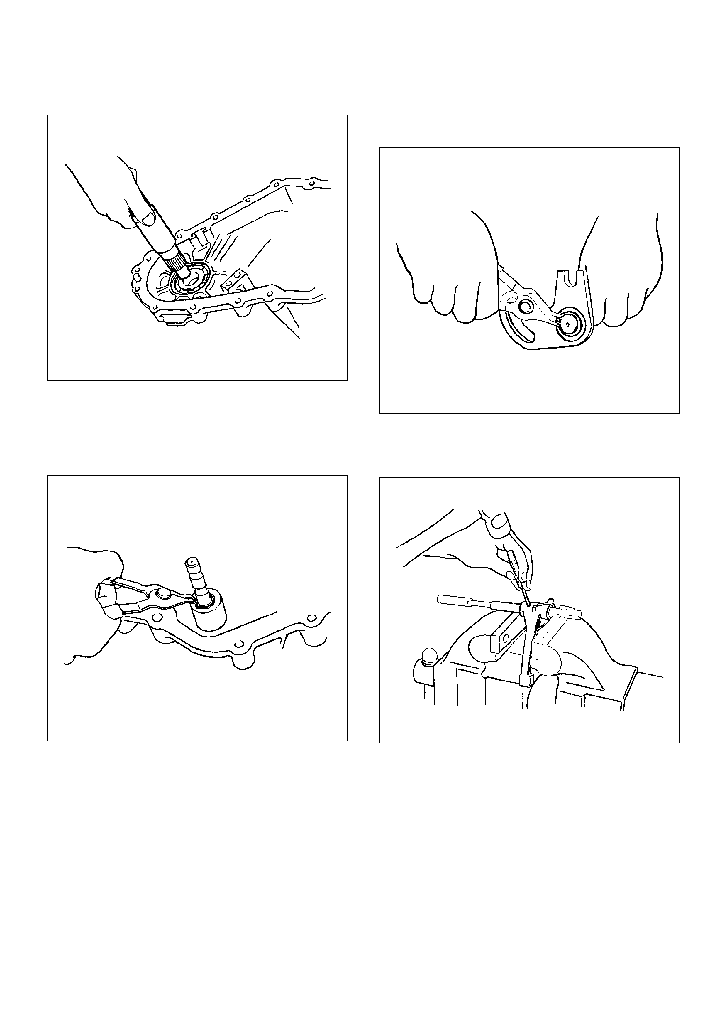
Disassembly
1. Using snap ring pliers, remove the snap ring.
261RW047
Legend
(1) Coil Assembly
(2) Snap Ring
(3) Ball Bearing
(4) Speed Gear and Tone Wheel
(5) Ball Bearing
(6) Transfer Cover Assembly
(7) Front and Rear Speed Sensors
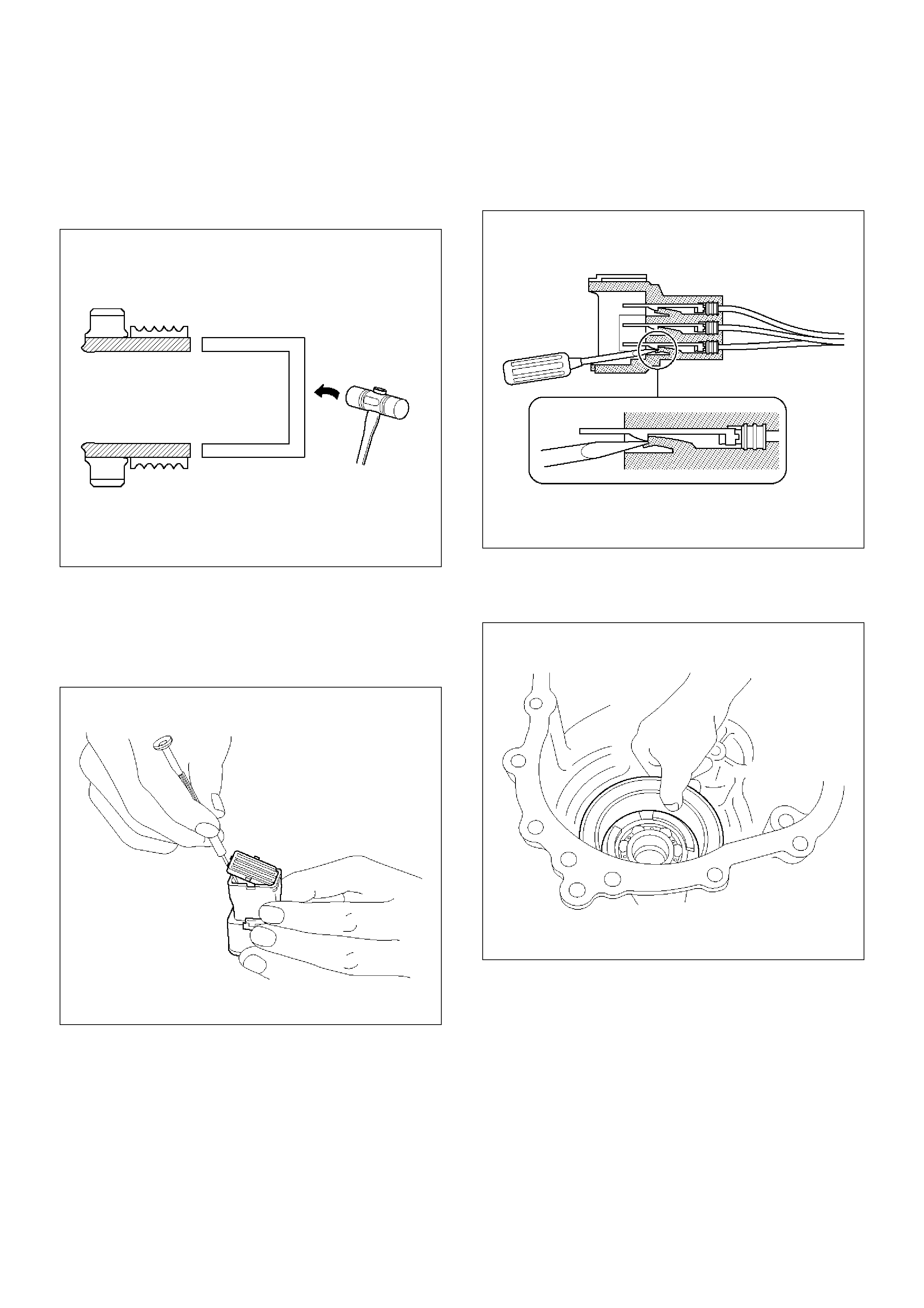
2. Strike the speed gear and tone wheel with a rod or
other appropriate tool from the outside of the
transfer cover assembly, and remove the ball
bearing and speed gear and tone wheel.
NOTE: Be careful not to damage the speed gear teeth.
266RW018
3. Remove the stopper plate on the back with a
precision screwdriver or other appropriate tool
starting from the small lock of the plate.
NOTE: Be careful not to damage the stopper plate
during the work.
261RW042
4. Using a terminal pull-out tool or an equivalent tool,
push down the lock to unlatch the terminal for the
coil assembly, and pull the terminal out.
NOTE: Be careful not to damage other terminals.
261RW032
5. Remove the fixing nuts of the coil assembly from the
outside of the transfer cover assembly. Remove the
coil assembly from the transfer cover.
261RW030
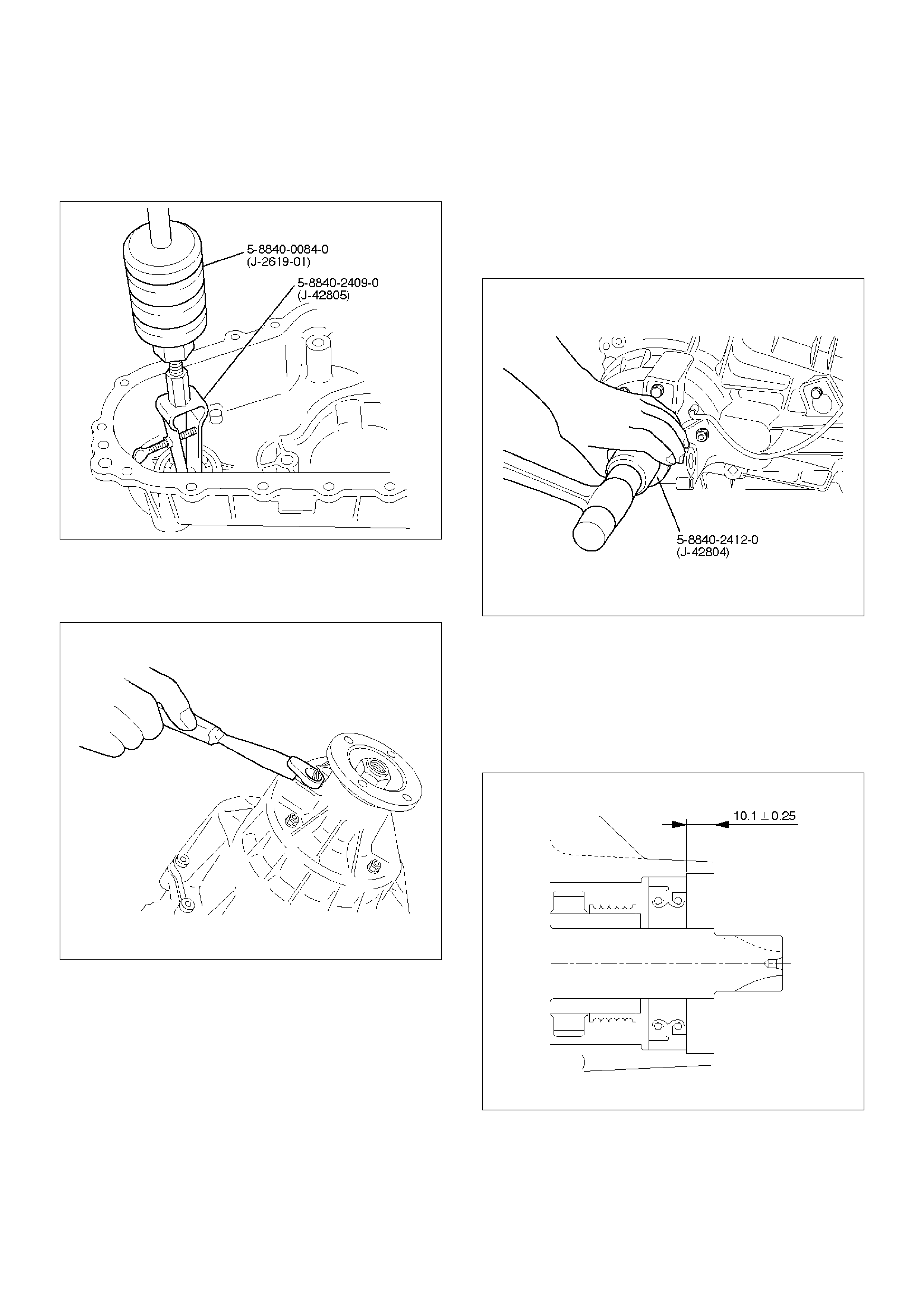
6. Using the bearing remover 5-8840-2409-0
(J-42805) and slide hammer 5-8840-0084-0
(J-2619-01), remove the ball bearing for the front
output shaft.
901RW234
7. Remove the bolts and front and rear speed sensors.
NOTE: Be careful not to damage the speed sensors
during the work.
261RW033
Reassembly
1. Remove the oil seal from the transfer cover
assembly.
2. Apply oil to the circumference of the new oil seal
and fill the lip with grease (Besco L2 or equivalent).
3. Using the oil seal installer 5-8840-2412-0 (J-42804),
install the oil seal to the transfer cover assembly.
261RW051
Rear Output Shaft Oil Seal
Distance between the transfer case end and oil seal.
NOTE: When installing the oil seal to the specified
dimension, be careful not to damage it.
Dimension : 9.85—10.35mm (0.39—0.41in)
A04RW004
1. Apply a thin coat of grease to the seal ring of each
front and rear speed sensor, and mount the sensors
carefully.
2. Tighten the bolts to the specified torque.
Torque : 5 N·m (0.5 kg·m/43lbin)
NOTE: Pay attention not to mount the front (or rear)
sensor to the rear (or front) sensor position.
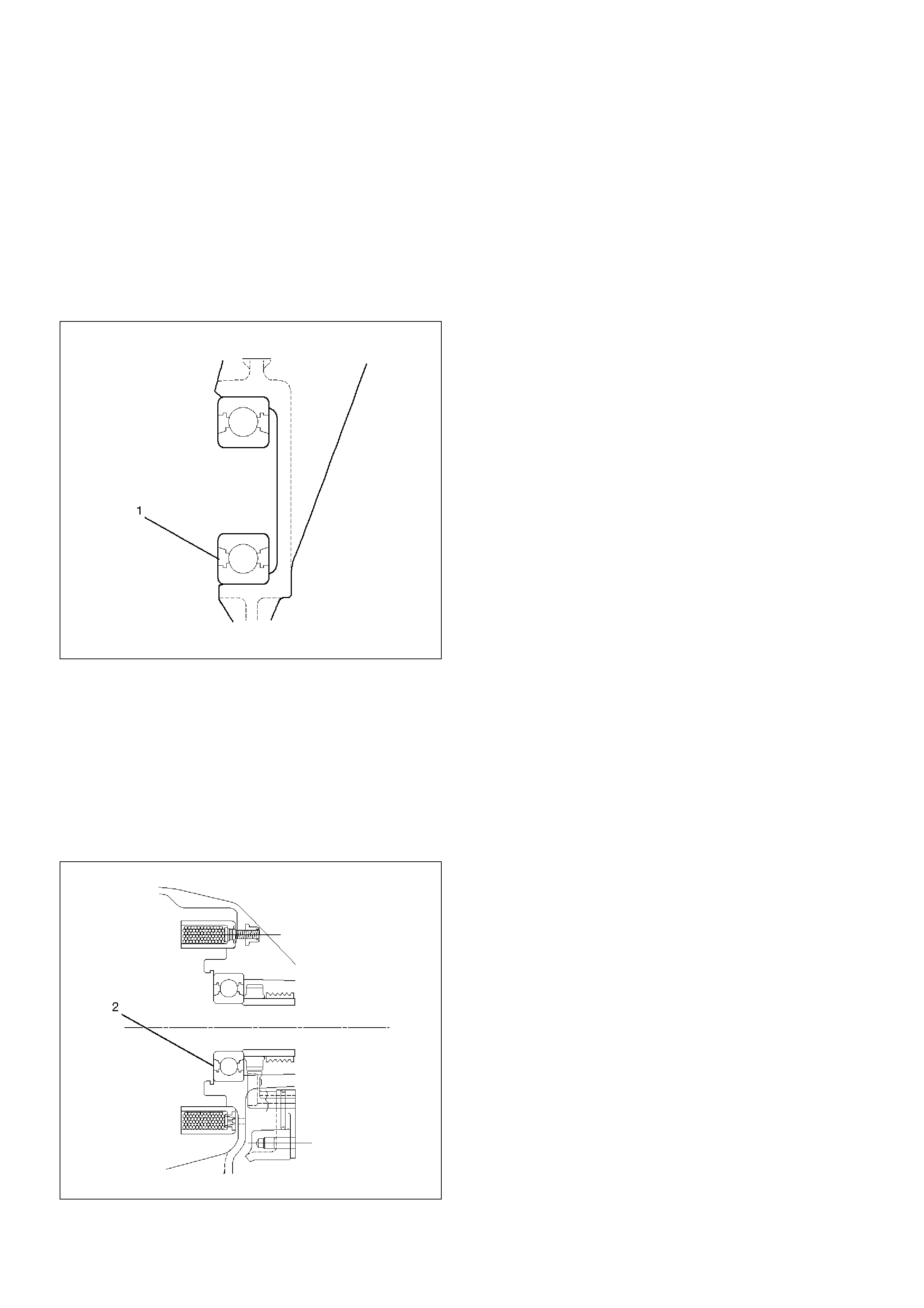
3. Install the ball bearing (1) for the front output shaft
as flat as shown in the figure.
261RW008
4. Mount the coil assembly and tighten the nuts to the
specified torque.
Torque : 10 N·m (1.0kg·m/87lbin)
5. Connect the terminal in the central connector.
NOTE: Be careful not to damage other terminals.
6. Install speed gear and tone wheel.
7. Mount the ball bearing (2) as flat as shown in the
figure.
261RW009-1
8. Using snap ring pliers, install the snap ring to the
transfer cover assembly.
NOTE: Securely install the snap ring to the groove of
the transfer cover assembly.
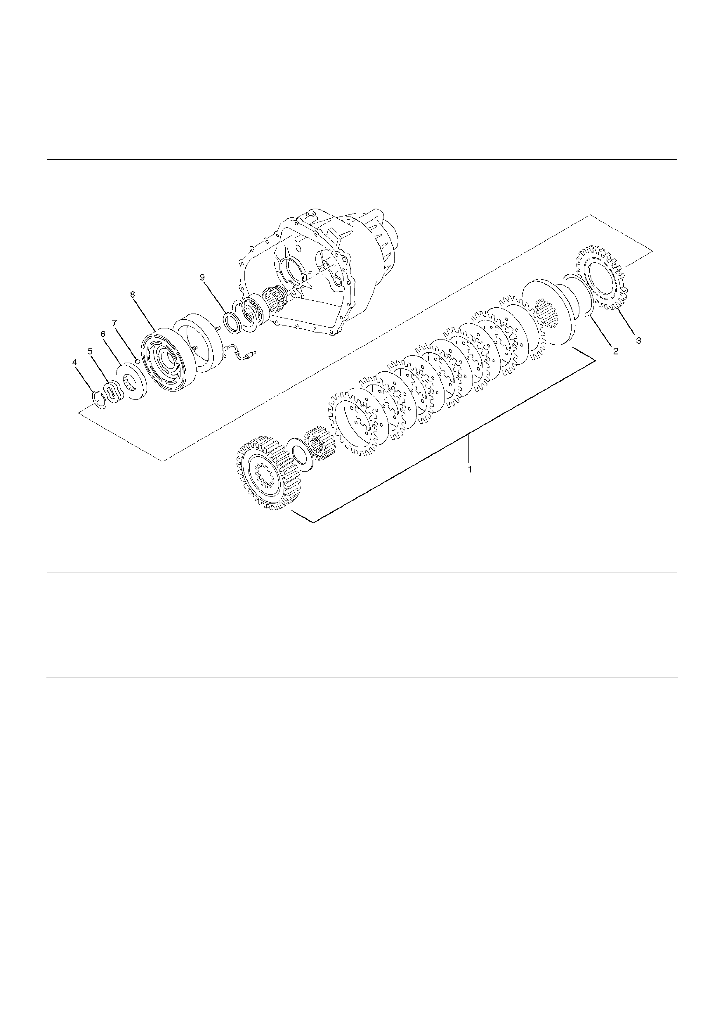
Transfer Case Assembly Clutch Pack and Clutch Cam
Disassembled View
266RW006
EndOFCallout
Disassembly
1. Remove the thrust bearing.
2. Remove the cam and coil housing.
NOTE: When the cam and coil housing is removed, the
cam balls may be detached together with the housing.
Be careful not to lose the ball.
Legend
(1) Clutch Pack Assembly
(2) Insulator Washer
(3) Armature Plate
(4) Snap Ring
(5) Wave Spring
(6) Cam Pulley
(7) Cam Ball
(8) Cam and Coil Housing
(9) Thrust Bearing
3. Remove the cam ball.
266RW013
4. Remove the cam pulley.
5. Remove the wave spring.
6. Using snap ring pliers, remove the snap ring.
NOTE: Be careful not to damage the snap ring.
266RW009
7. Remove the armature plate.
8. Remove the insulator washer.
9. Remove the clutch pack assembly as a package.
266RW017

Sprocket and Mechanical Lock
Disassembled View
266RW008
EndOFCallout
Disassembly
1. Remove the sprocket spacer.
2. Remove the front tone wheel.
Legend
(1) Strainer
(2) Hose
(3) Oil Pump Assembly
(4) Thrust Washer
(5) Mechanical Lock Hub
(6) Lock-up Sleeve
(7) Lock-up Fork
(8) Chain
(9) Lower Driven Sprocket
(10) Front Tone Wheel
(11) Drive Sprocket
(12) Sprocket Spacer
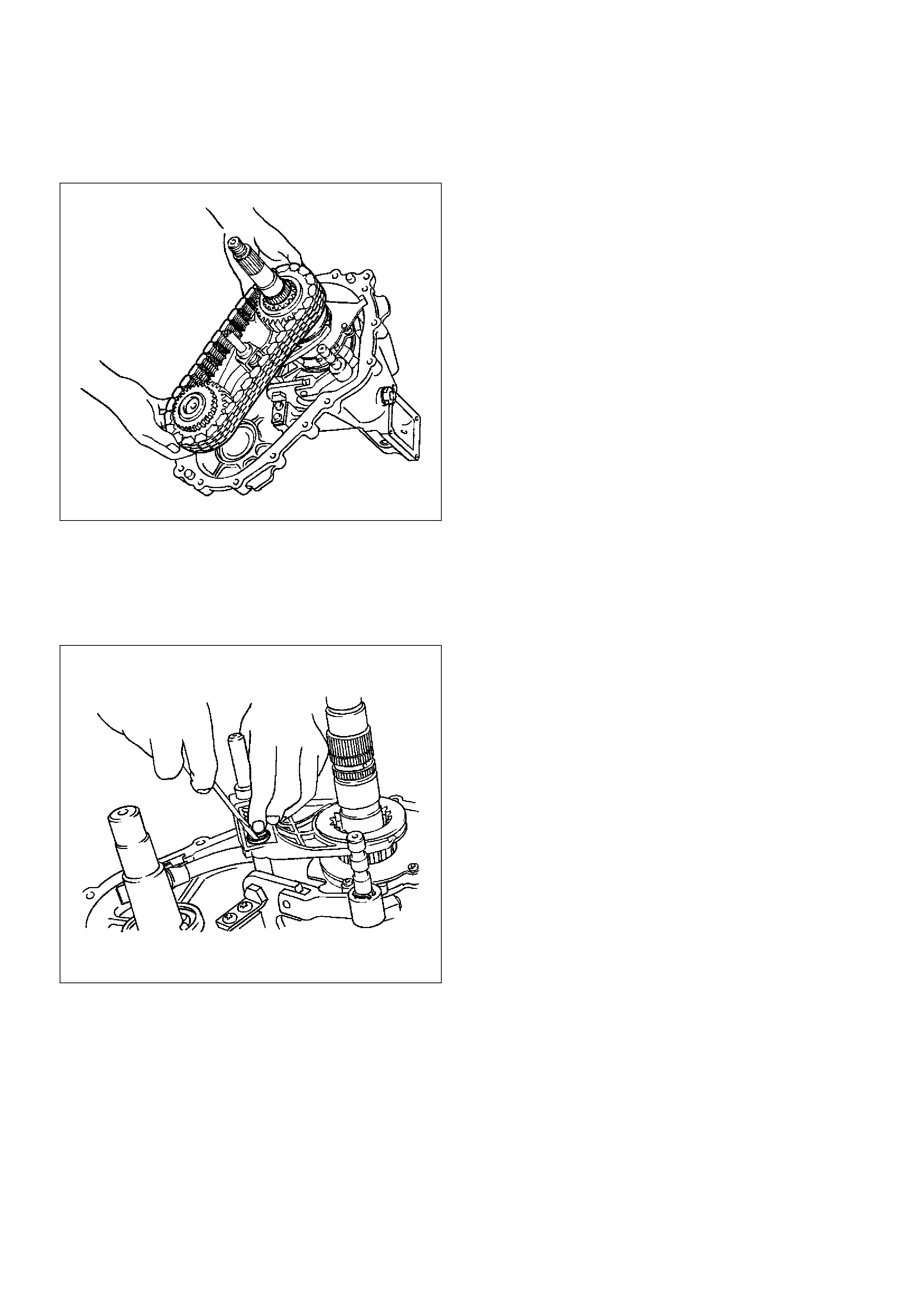
3. Remove the drive sprocket, lower driven sprocket,
and chain together from the front and rear output
shafts.
266RW010
4. Remove the mechanical lock hub.
5. Remove the lock-up fork.
6. Remove the spring retainers from the connection
between the rail shaft and lock-up fork.
7. Remove the lock-up sleeve.
261RW018
8. Remove the thrust washer.
9. Remove the magnet from the strainer set position
together with the oil pump assembly.
10. Remove the strainer from the oil pump assembly.
11. Remove the hose from the oil pump assembly.
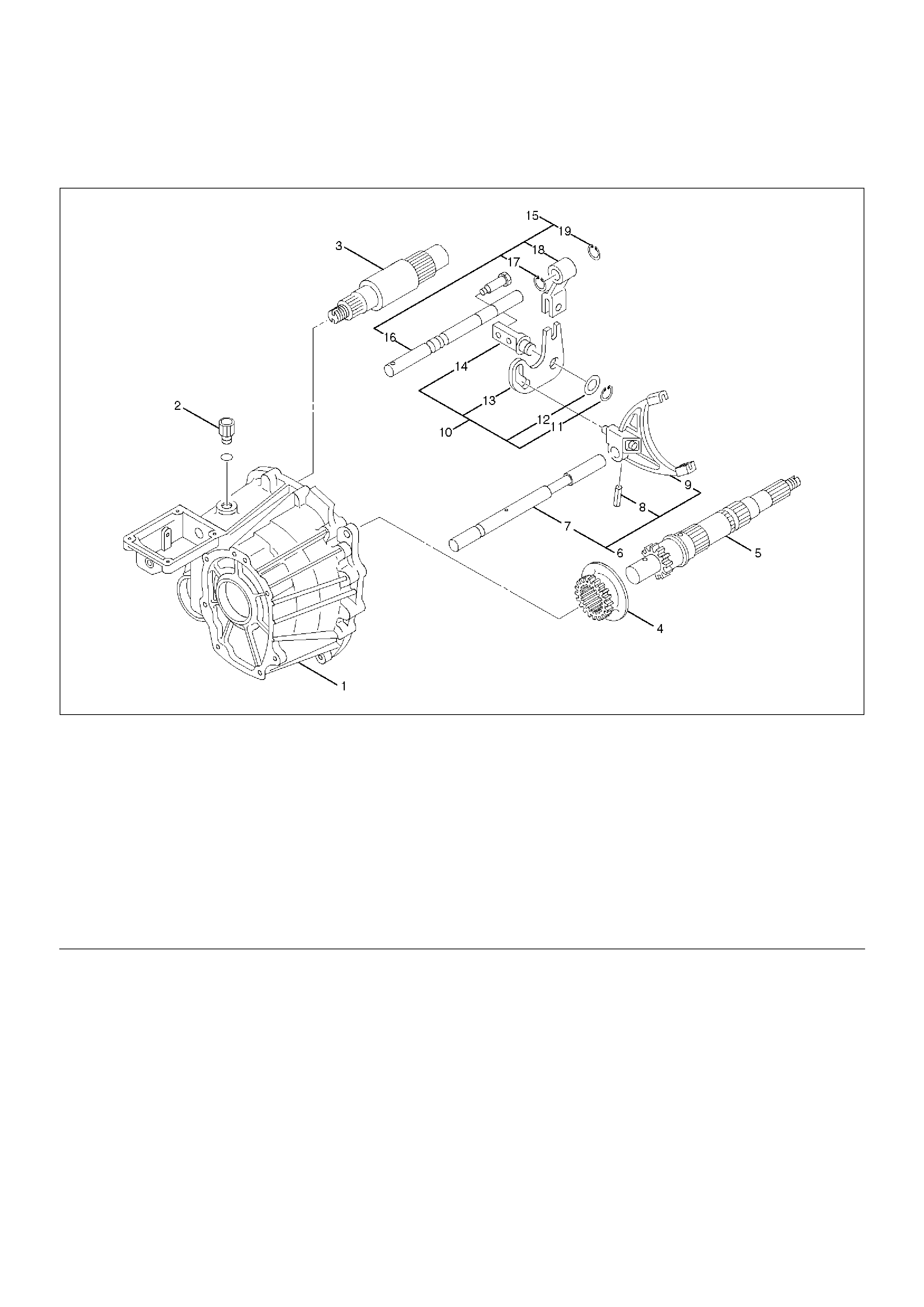
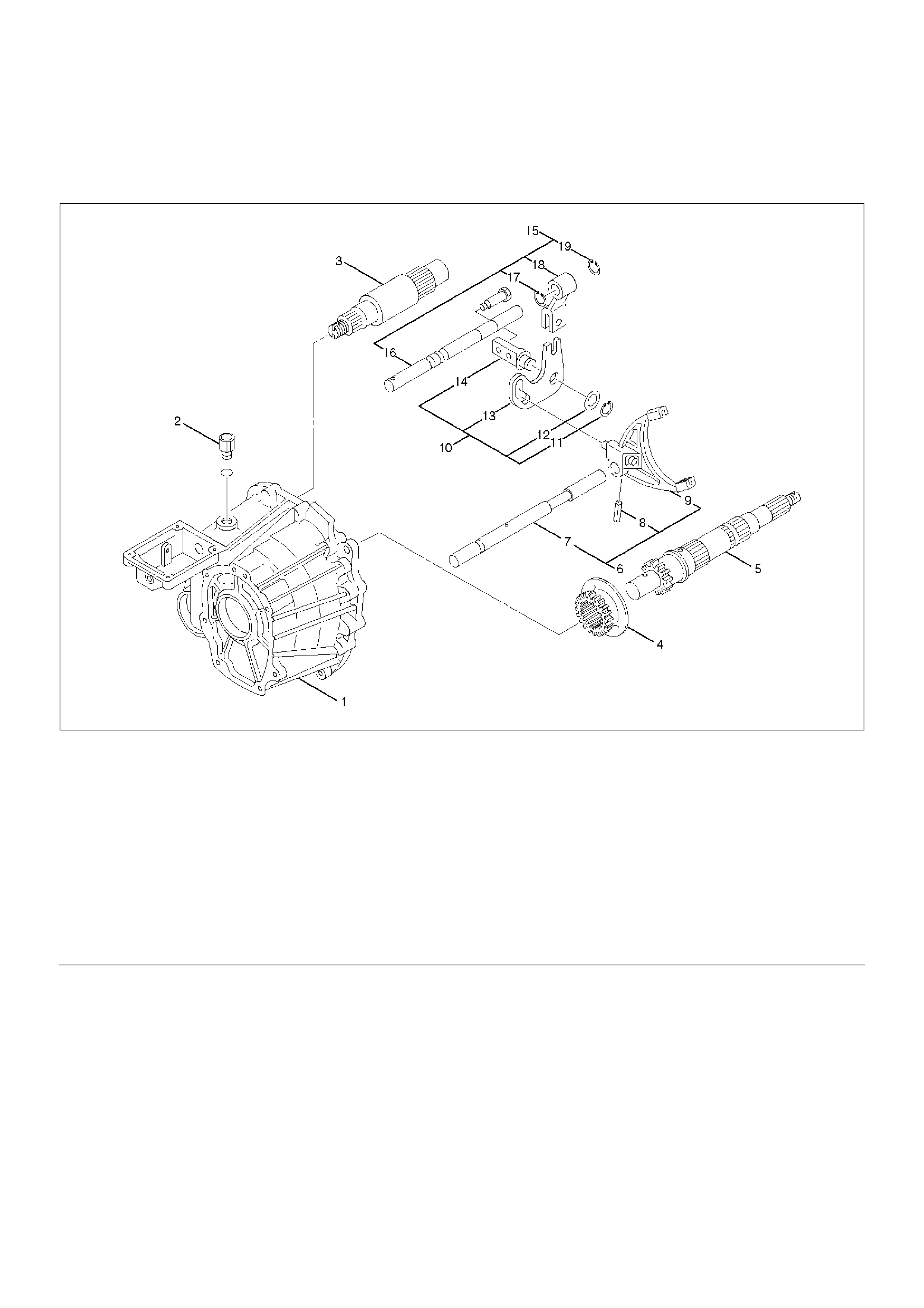
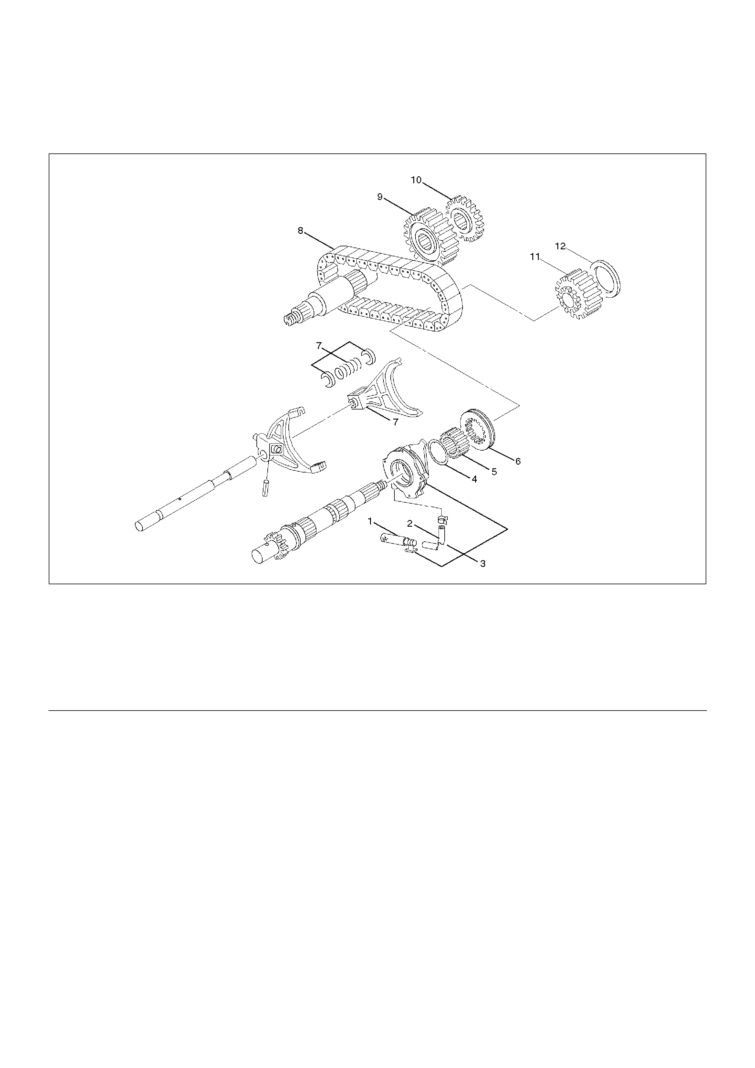
Output Shafts and Shift Control Shaft
Disassembled View
261RW010-1
EndOFCallout
Legend
(1) Transfer Case Assembly
(2) Detent Spring
(3) Front Output Shaft
(4) Reduction Hub
(5) Output Shaft
(6) Reduction Fork Assembly
(7) Lock-up Shaft
(8) Spring Pin
(9) Reduction Fork
(10) Cam Assembly
(11) Snap Ring
(12) Washer
(13) Cam
(14) Cam Pilot Block
(15) Shifter Shaft Assembly
(16) Shifter Lever Shaft
(17) Snap Ring
(18) Reduction Lever Assembly
(19) Snap Ring

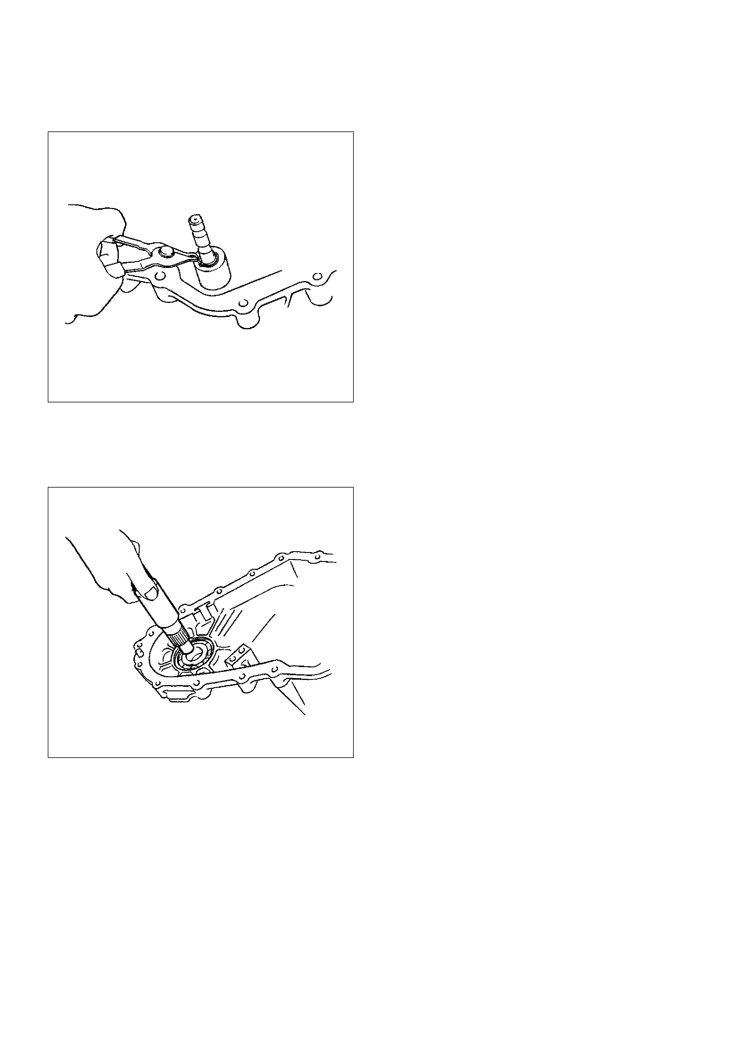
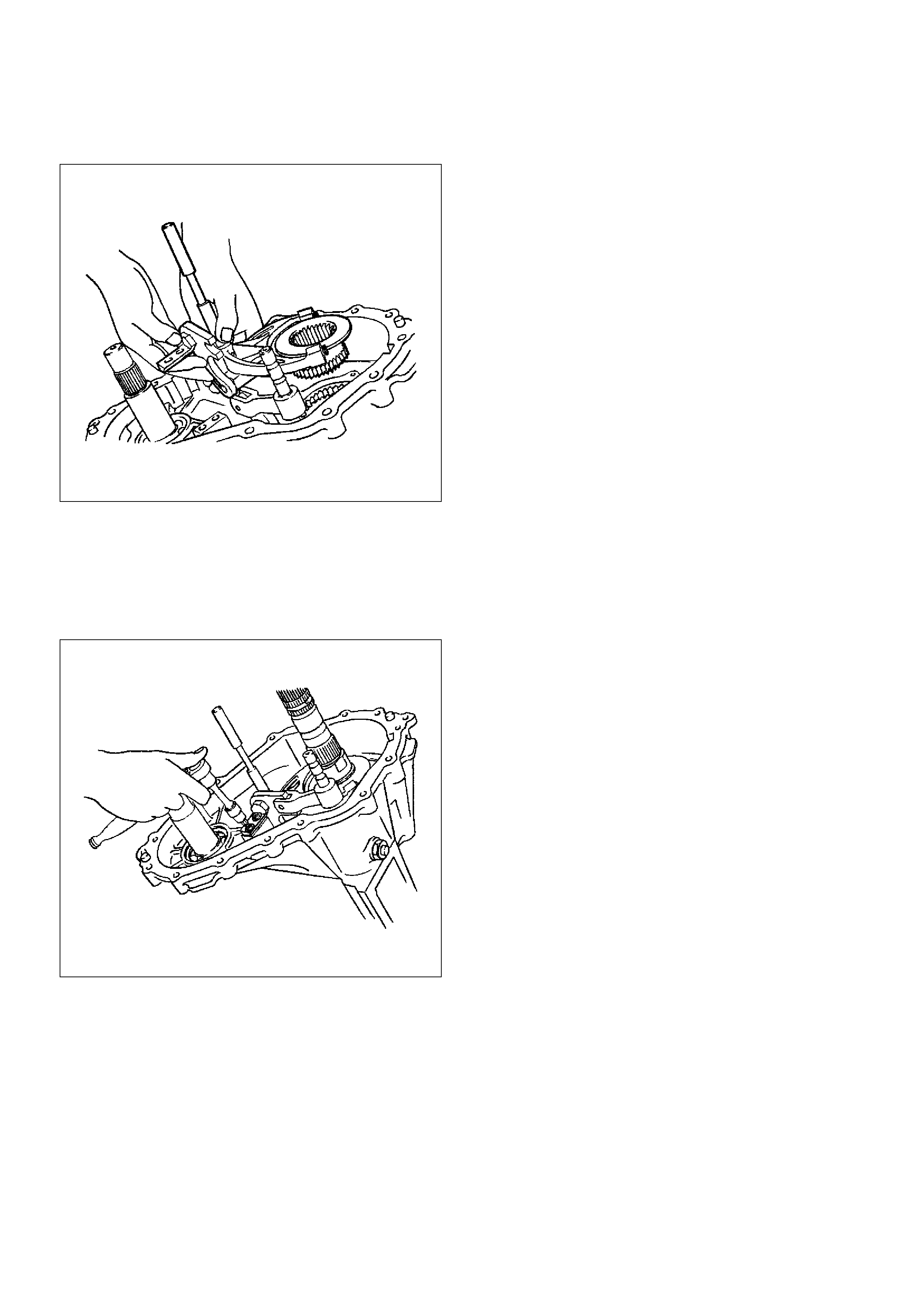
Disassembly
1. Remove the output shaft.
266RW011
2. Remove the detent spring.
3. Remove the cam pilot block bolts.
4. Remove the shifter shaft assembly and cam
assembly.
5. Remove the reduction fork assembly together with
reduction hub.
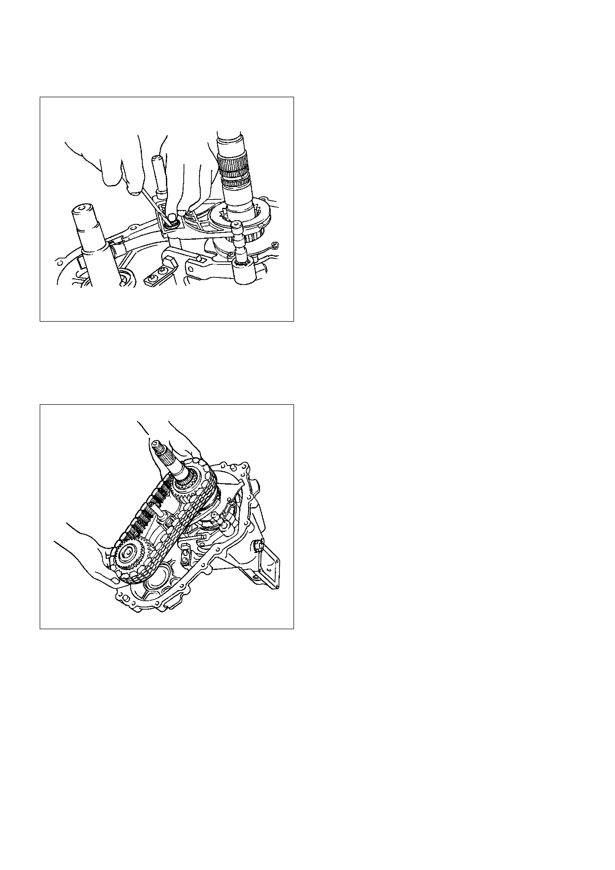
261RW019
6. Remove the spring pin that fixes the reduction fork
to the lock-up shaft.
261RW020
7. Remove the reduction fork.
8. Remove the lock-up shaft.
9. Using snap ring pliers, remove the snap ring from
cam pilot block.
261RW029
10. Remove the washer.
11. Remove the cam.
12. Remove the cam pilot block.
13. Using snap ring pliers, remove the snap ring from
the shifter shaft assembly.
261RW021
14. Remove the reduction lever assembly.
15. Remove the snap ring.
16. Remove the shifter lever shaft.
17. Remove the front output shaft.
266RW012
18. Remove the transfer case assembly.

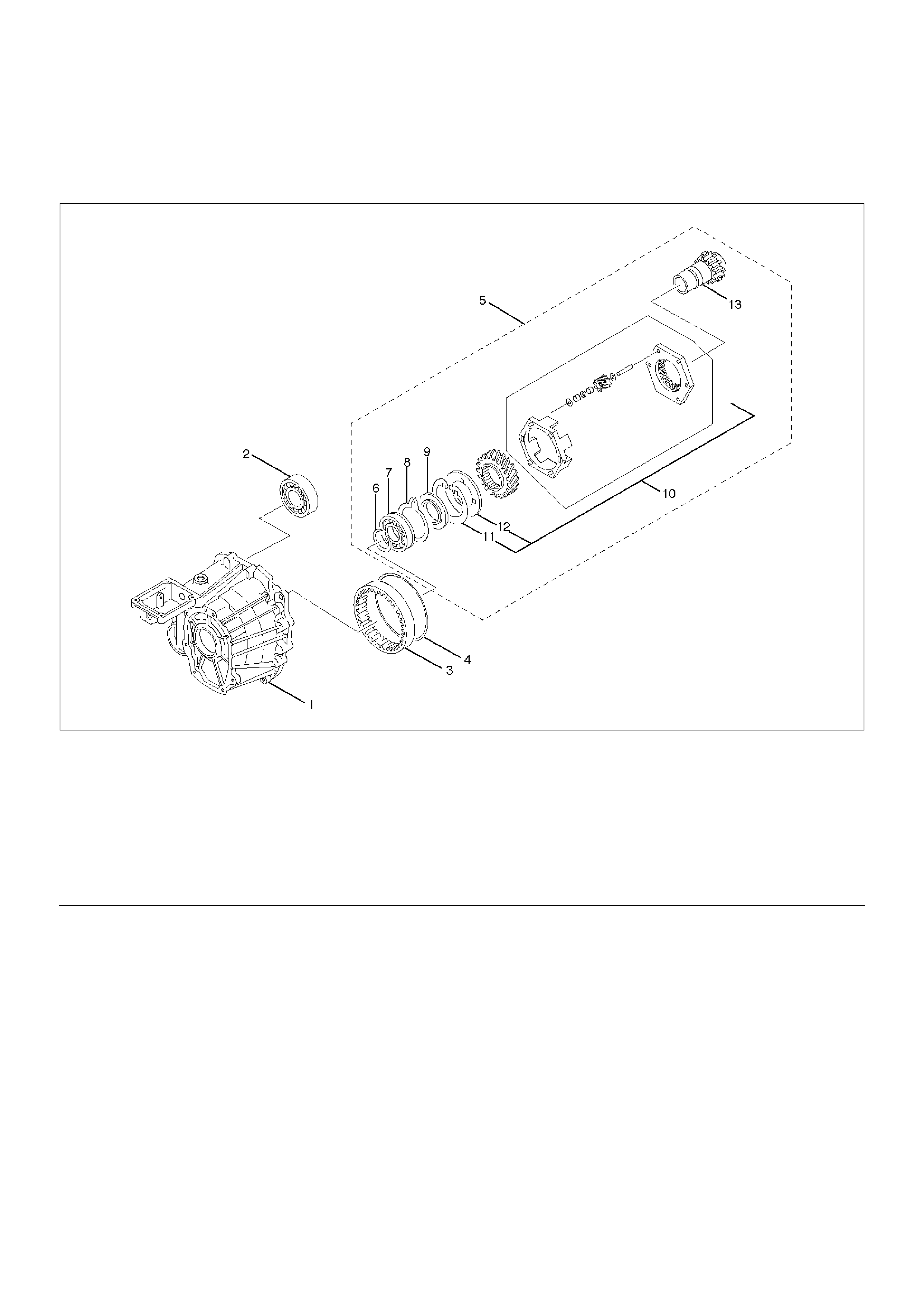
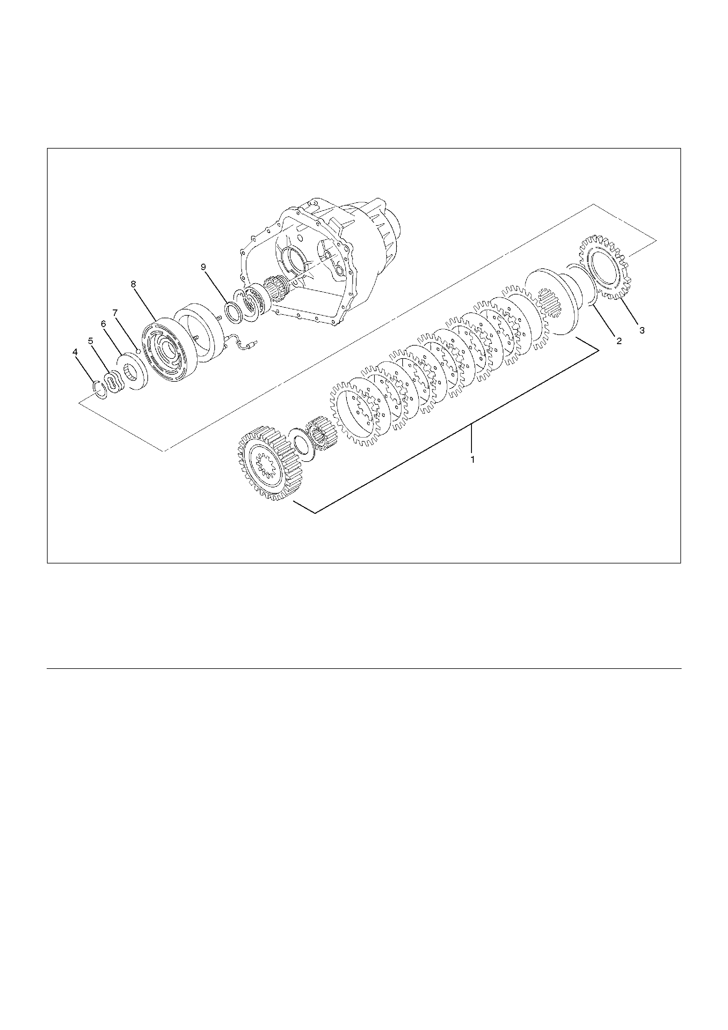
Transfer Case
Disassembled View
265RW015
EndOFCallout
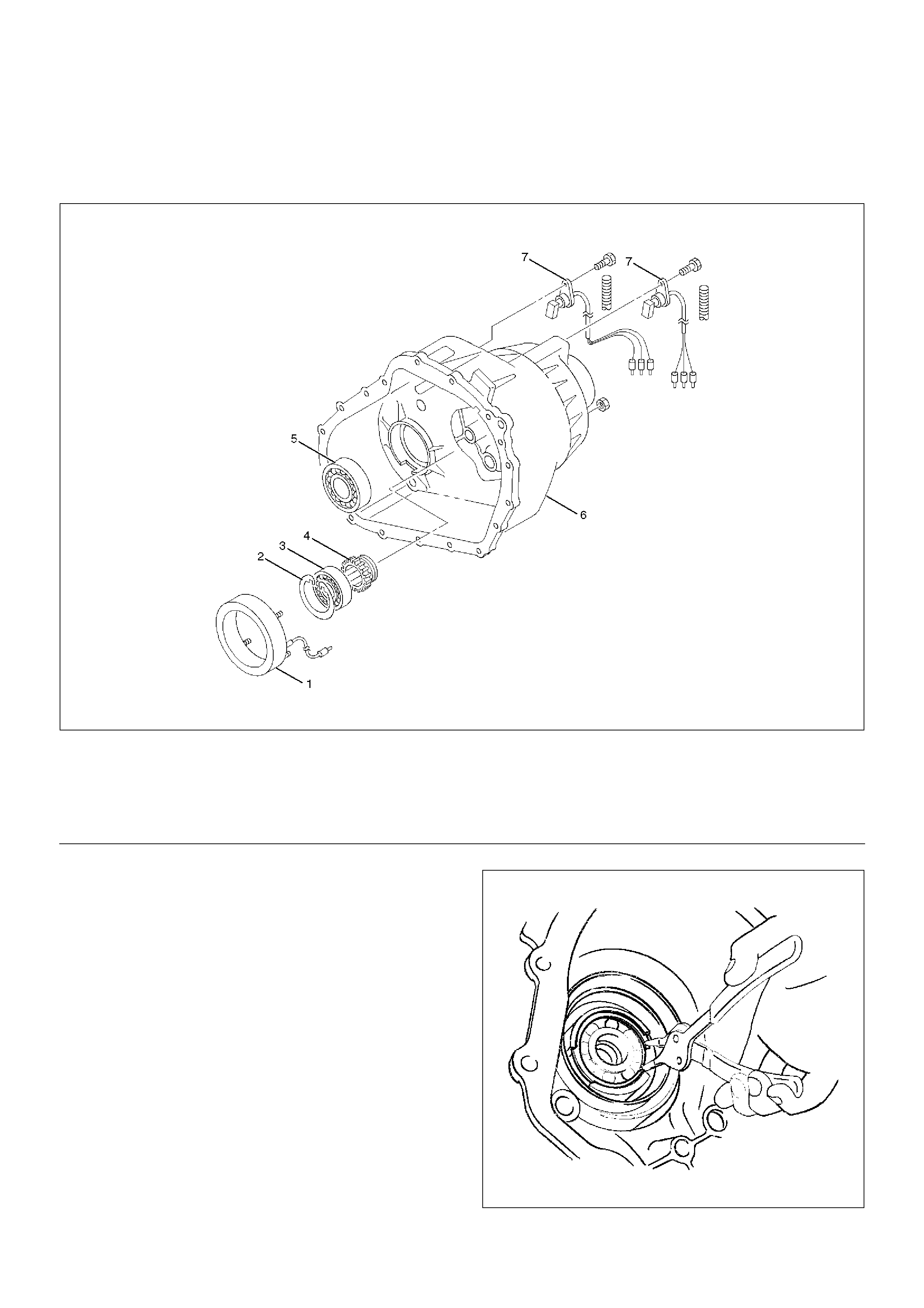
Legend
(1) Transfer Case
(2) Ball Bearing
(3) Ring Gear
(4) Snap Ring
(5) Input Shaft and Carrier Assembly
(6) Snap Ring
(7) Ball Bearing
(8) Snap Ring
(9) Thrust Plate
(10) Carrier Assembly
(11) Snap Ring
(12) Circular Hub
(13) Input Shaft
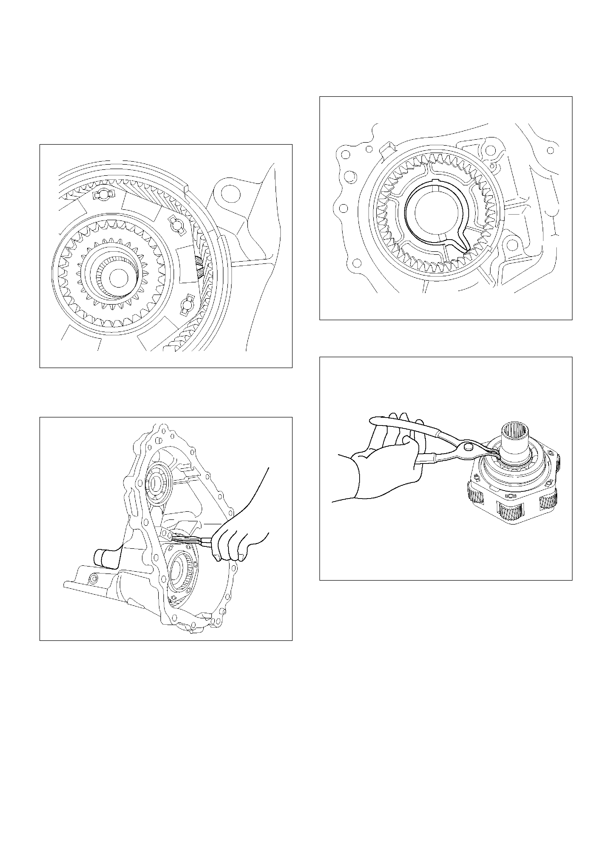
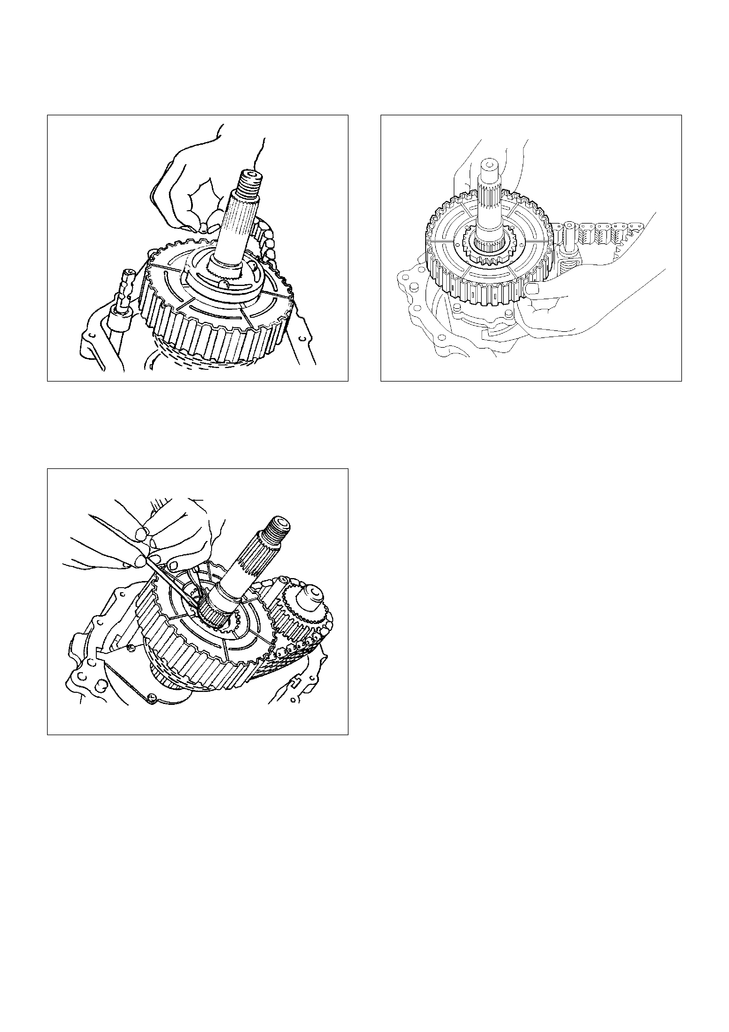
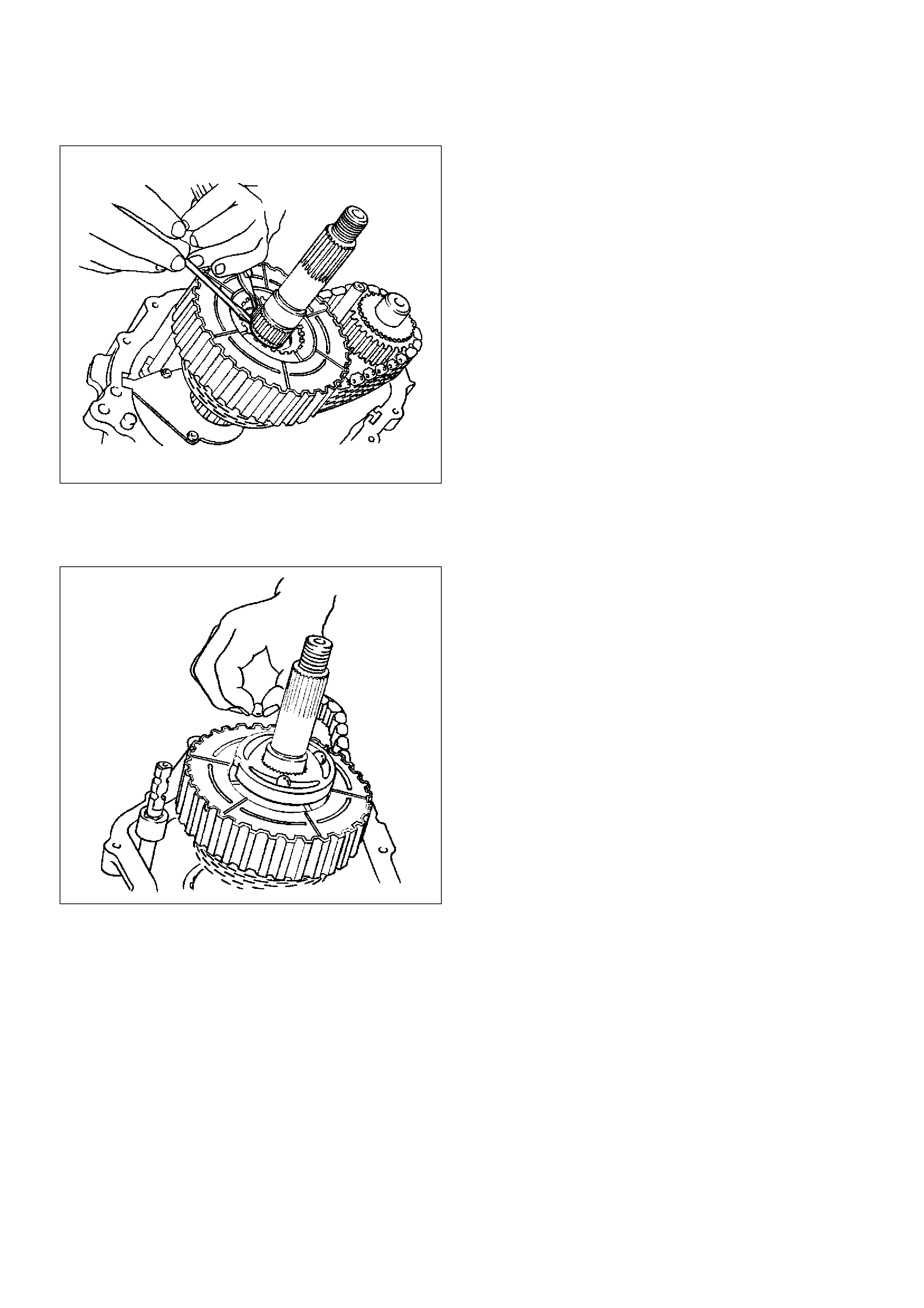
Disassembly
1. Remove the ball bearing (for front output shaft).
2. Expand the snap ring through the opening in the
planetary gear assembly.
261RW040
3. While expanding the snap ring, remove the input
shaft, ball bearing, carrier assembly, and thrust plate
from the transfer case.
261RW037
4. Remove the snap ring from the transfer case.
261RW036
5. Using snap ring pliers, remove the snap ring before
the ball bearing.
265RW009
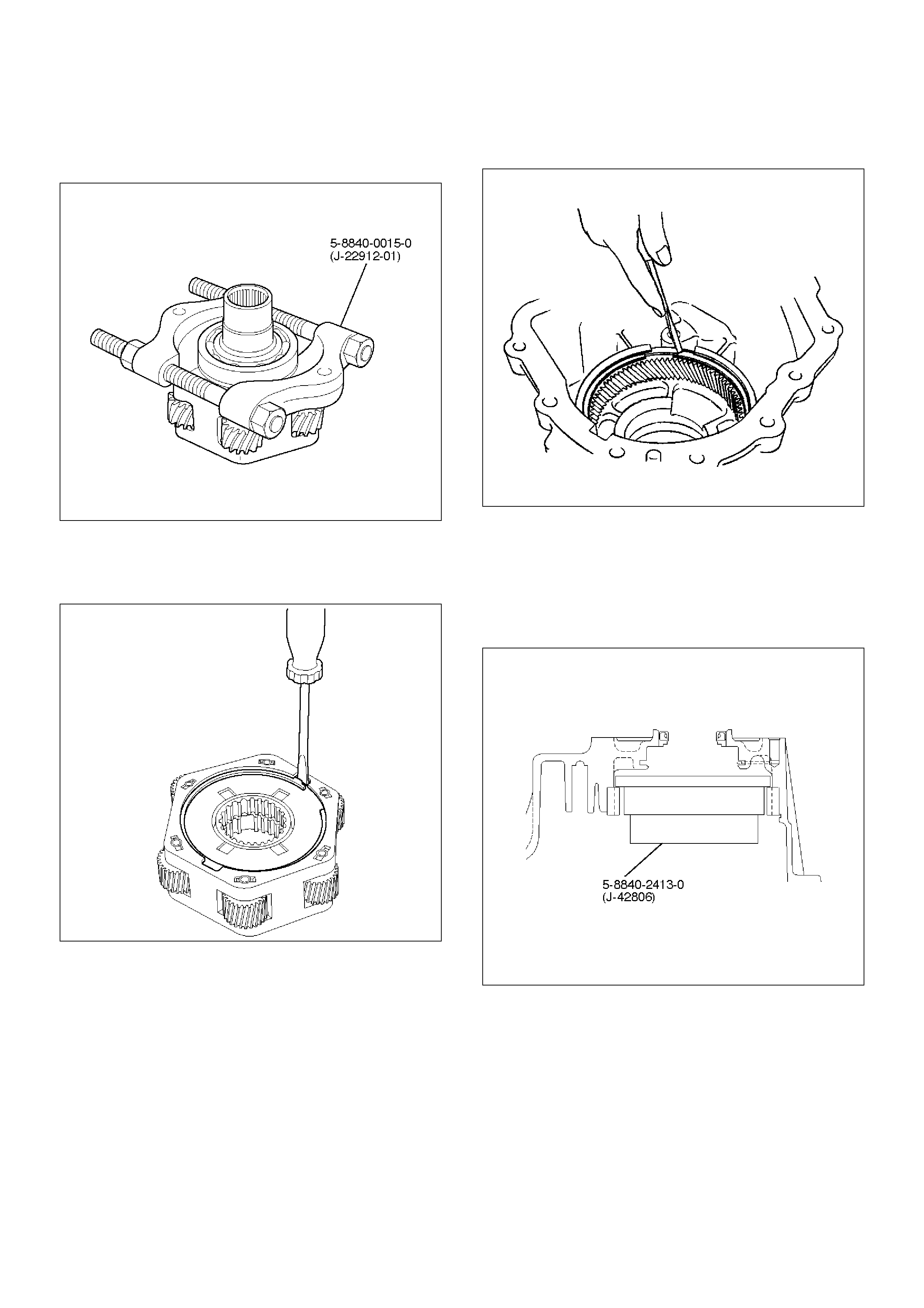
6. Using the bearing remover 5-8840-0015-0
(J-22912-01), remove the ball bearing from the input
shaft.
265RW014
7. Remove the thrust plate.
8. Remove the carrier assembly.
9. Remove the snap ring from the carrier assembly.
265RW006
10. Remove the circular hub.
11. Remove the snap ring before the ring gear.
261RW025
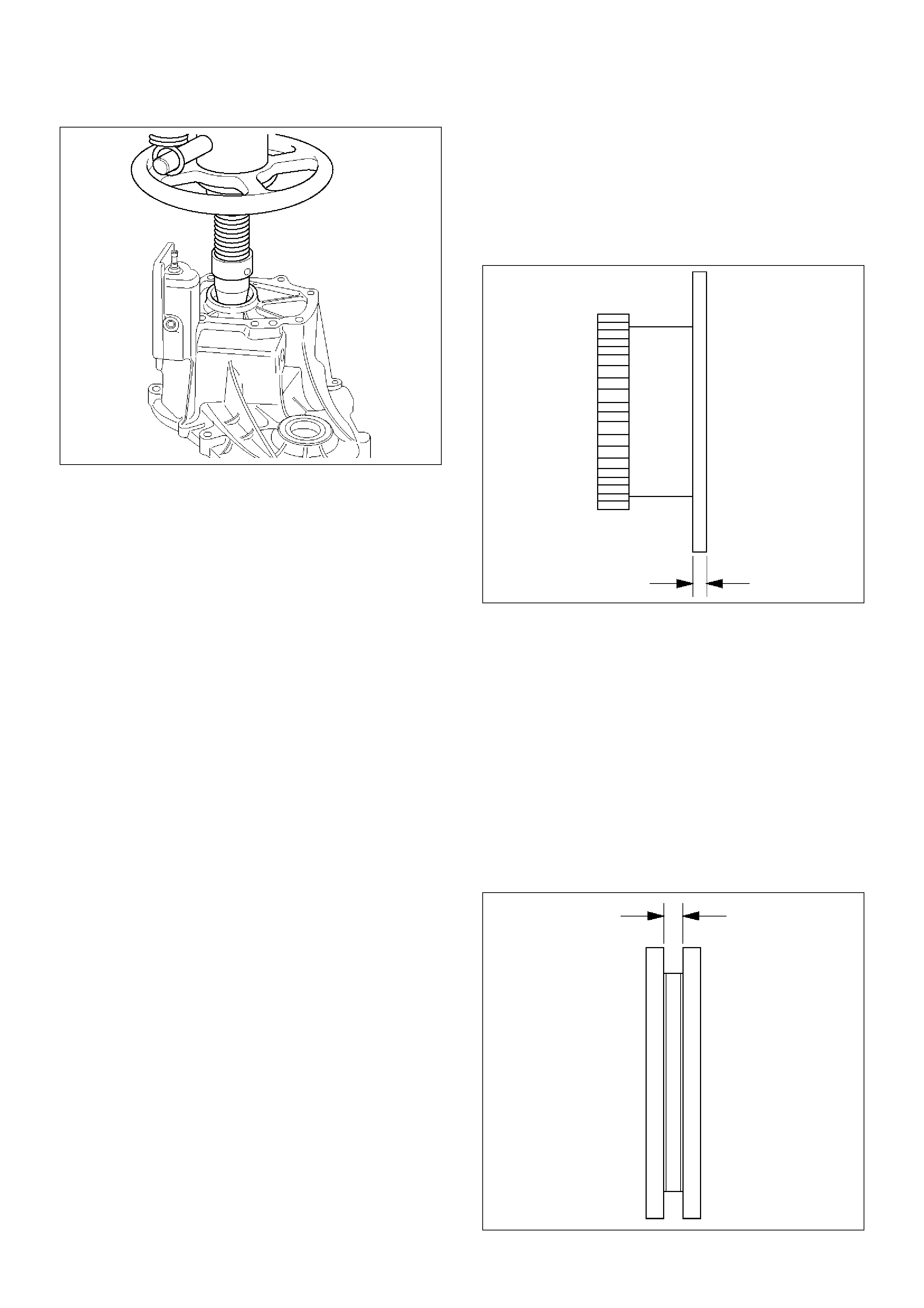
12. Using the replacer 5-8840-2413-0 (J-42806),
remove the ring gear.
NOTE: Removing the ring gear needs a high-load
press. This means the transfer case may be damaged.
To remove and replace the ring gear, it is recommended
that the transfer case assembly should be replaced.
261RW050
265RW007
Inspection and Repair
When wear, damage, or any other defects are observed
during the inspection, the part or parts must be repaired
or replaced. Wash all the parts with clean solvent, and
check that old oil, metallic particles, dirt, or foreign
materials are completely removed. Blow the air into oil
holes and grooves to remove foreign materials or
residual detergent.
Chain
• Check whether the face that contacts the sprocket is
free from excessive wear or damage. If defects are
observed, replace the part.
• If the chain interference mark is found on the inside
wall of the transfer cover or the chain is so slack that
a skipped engagement occurs between the chain and
sprocket, replace the chain.
Sprocket
• Check whether the sprocket tooth surface is
excessively worn or damaged, and there is evidence
of burrs, chipping, wear, or damage on the gear
spline. Remove minor flaws or scratches with oil
stone. If excessive wear or damage is observed,
replace the part.
• If excessive wear or damage is observed on the
sprocket inside sliding surface, replace the part.
Gear
Check whether the gear tooth surface is excessively
worn or damaged, and there is evidence of burrs,
chipping, wear, or damage on the gear spline.
Remove minor flaws or scratches with oil stone. If
excessive wear or damage is observed, replace the
part.
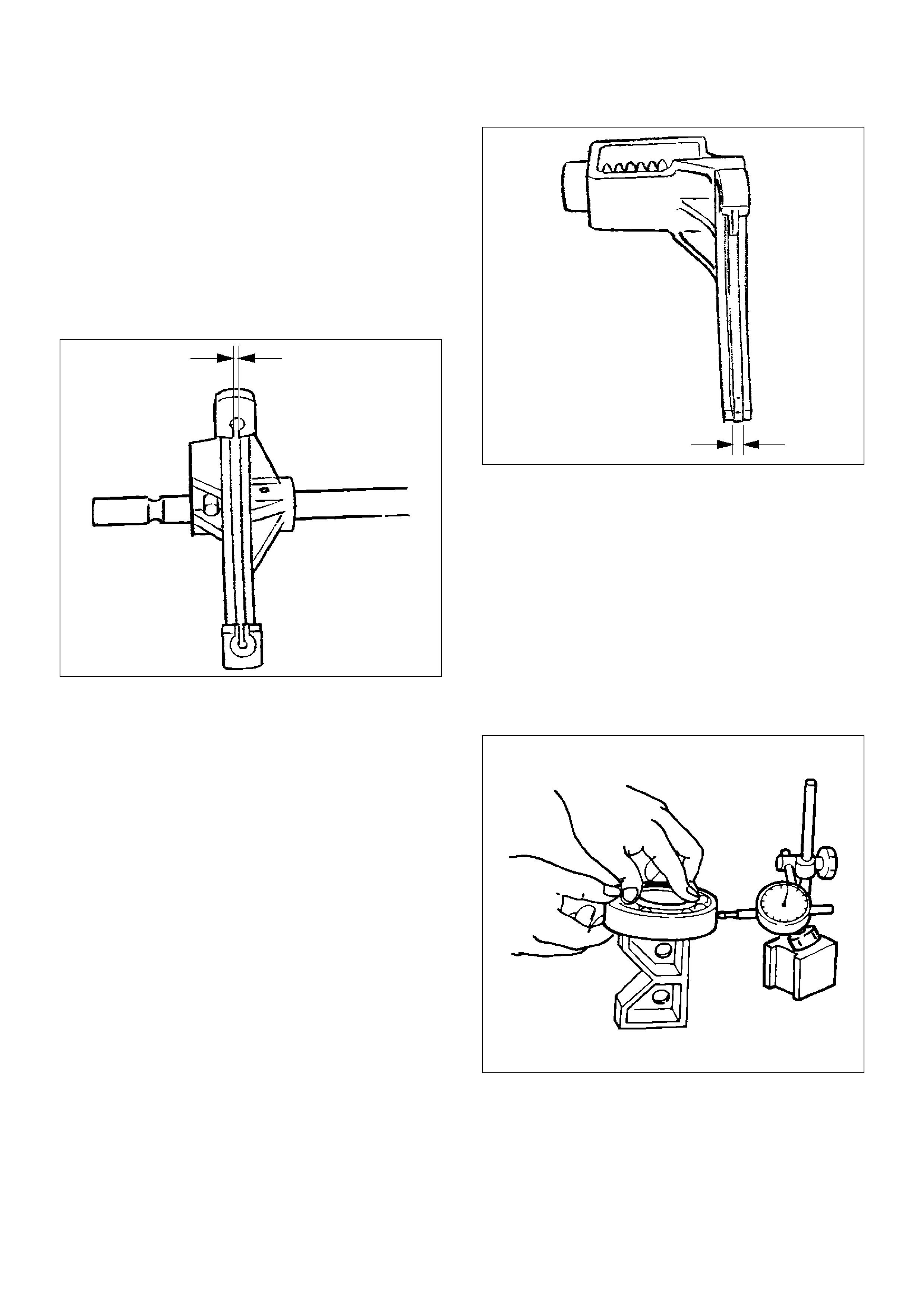
Thickness of Reduction Hub
• Measure the thickness with a micrometer.
• If the measurement exceeds the limit, replace the
reduction hub.
Standard : 3.05-3.30 mm (0.120-0.130 in)
Allowable limit : 2.5 mm (0.098 in)
265RW005
Lock-up Sleeve
Mount the mechanical lock hub, drive sprocket
assembly, and lock-up sleeve to the output shaft.
If the lock-up sleeve does not move smoothly, replace
the sleeve.
NOTE: Apply ATF to the area engaging the gear.
Thickness of Lock-up Sleeve
• If the measurement exceeds the limit, replace the
lock-up sleeve.
Standard : 7.16-7.32 mm (0.282-0.288 in)
Allowable limit : 7.9 mm (0.311 in)
266RW014
Reduction Fork
Check the reduction fork and shaft for wear, distortion,
and scratches. If defects are observed, replace the
parts.
Thickness of Reduction Fork
• If the measurement exceeds the limit, replace the
reduction fork.
Standard : 3.41-3.79 mm (0.134-0.149 in)
Allowable limit : 4.4 mm (0.173 in)
261RW026
Lock-up Fork
• Check the lock-up fork and shaft for wear, distortion,
and scratches. If defects are observed, replace the
parts.
Thickness Lock-up Fork
If the measurement exceeds the limit, replace the
lock-up fork.
Standard : 6.99-7.09 mm (0.275-0.279 in)
Allowable limit : 6.3 mm (0.248 in)
261RW027
Bearing
Check the profile of the needle, roller, ball, and thrust
bearings. Wash the bearings with clean solvent
completely, and dry with air.
NOTE: If the bearing is rotated excessively, the rollers
may be damaged. So, rotate the bearing slowly with
your hand. Apply grease to the bearing, and check the
smoothness of the bearing while slowly rotating the race
with your hand.
• Use a dial indicator to measure the ball bearing play.
Allowable limit : 0.23 mm (0.009 in)
226RW143
Lock-up Fork Spring
Check the lock-up fork spring for distortion, cracking,
and wear. If defects are observed, replace the part.
Free Length of the Lock-up Fork Spring
• If the measurement exceeds the limit, replace the
spring.
Standard : 60.96 mm (2.40 in)
Allowable limit : 55.0 mm (2.17 in)
220RW045
Tension of Lock-up Fork Spring
• If the measurement exceeds the limit, replace the
spring. (When compressed to 41.4 mm)
Standard : 27.1-33.8 N {2.76-3.45kg/6.08-7.61Ib}
Allowable limit : 24.5 N {2.5kg/5.5Ib}
014RW048
Tension of Detent Spring Assembly
• If the measurement exceeds the limit, replace the
spring. N {kg} (When compressed by 3 mm from the
free length)
Standard : 139 N -203 {14.2-20.7kg/31.3-45.6Ib}
Allowable limit : 130 N {13.3kg/29.3Ib}
261RW041
Oil Pump
• Remove foreign materials from the strainer. If the
strainer is damaged, replace it.
• If the area into which the shaft is inserted is
excessively worn or damaged, replace the pump.
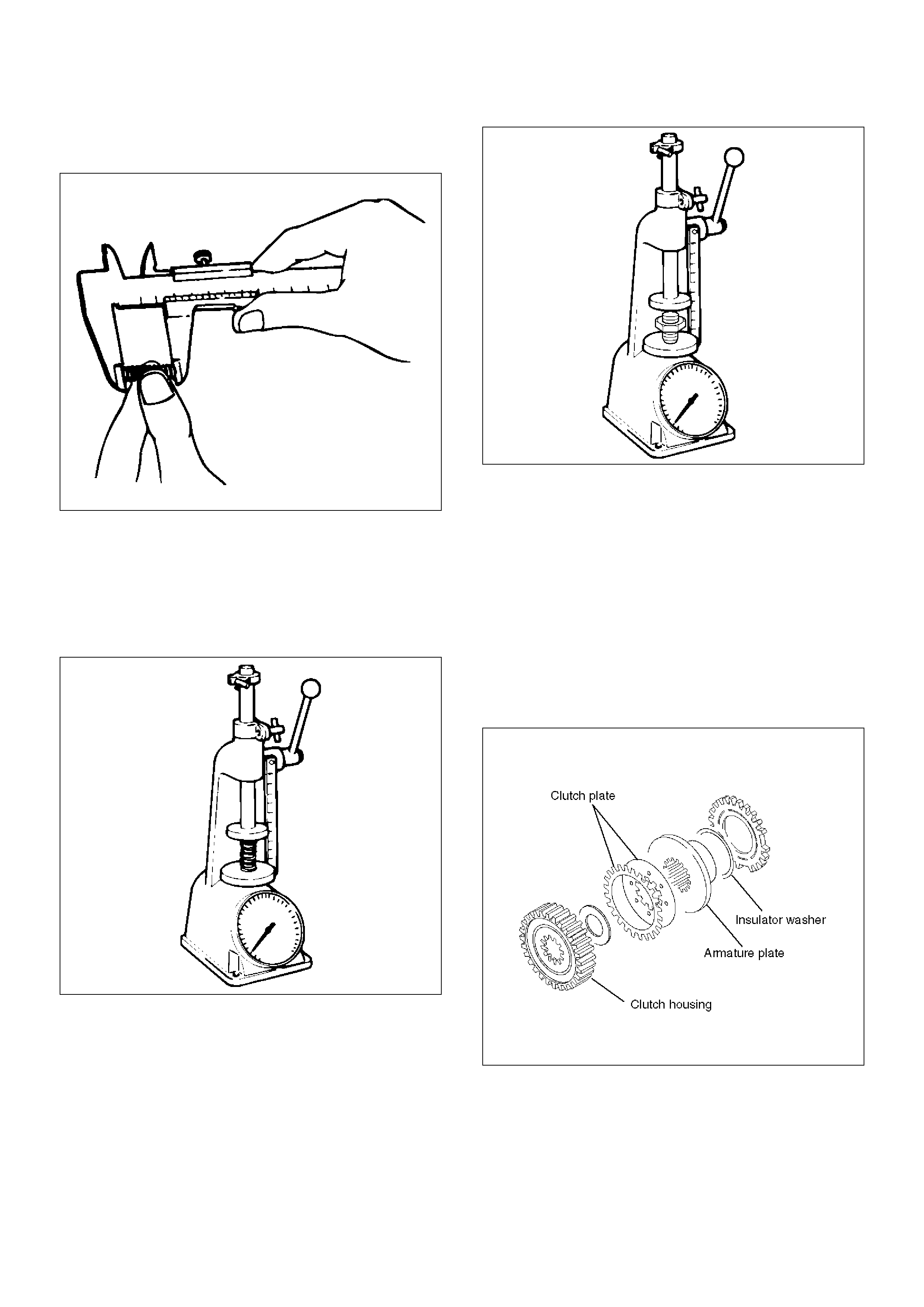
Multi Plate Disk Clutch
• If the burned, mirror-surfaced clutch facing, or
scraping is observed on the clutch plates, clutch
housing, armature plate, and insulator washer,
replace the part or parts.
266RW003
Coil Assembly
• Check the resistance of the coil with a tester. If
defects are observed, replace the assembly.
* (ordinary temperature)
Standard : 1.4~2.0 W
Allowable limit : 1.0~5.0 W
261RW031
Cam Pulley, Cam Ball, and Cam&Coil
Housing
• Check the cam balls and cam for excessive wear or
damage. If defective, replace the parts.
266RW016
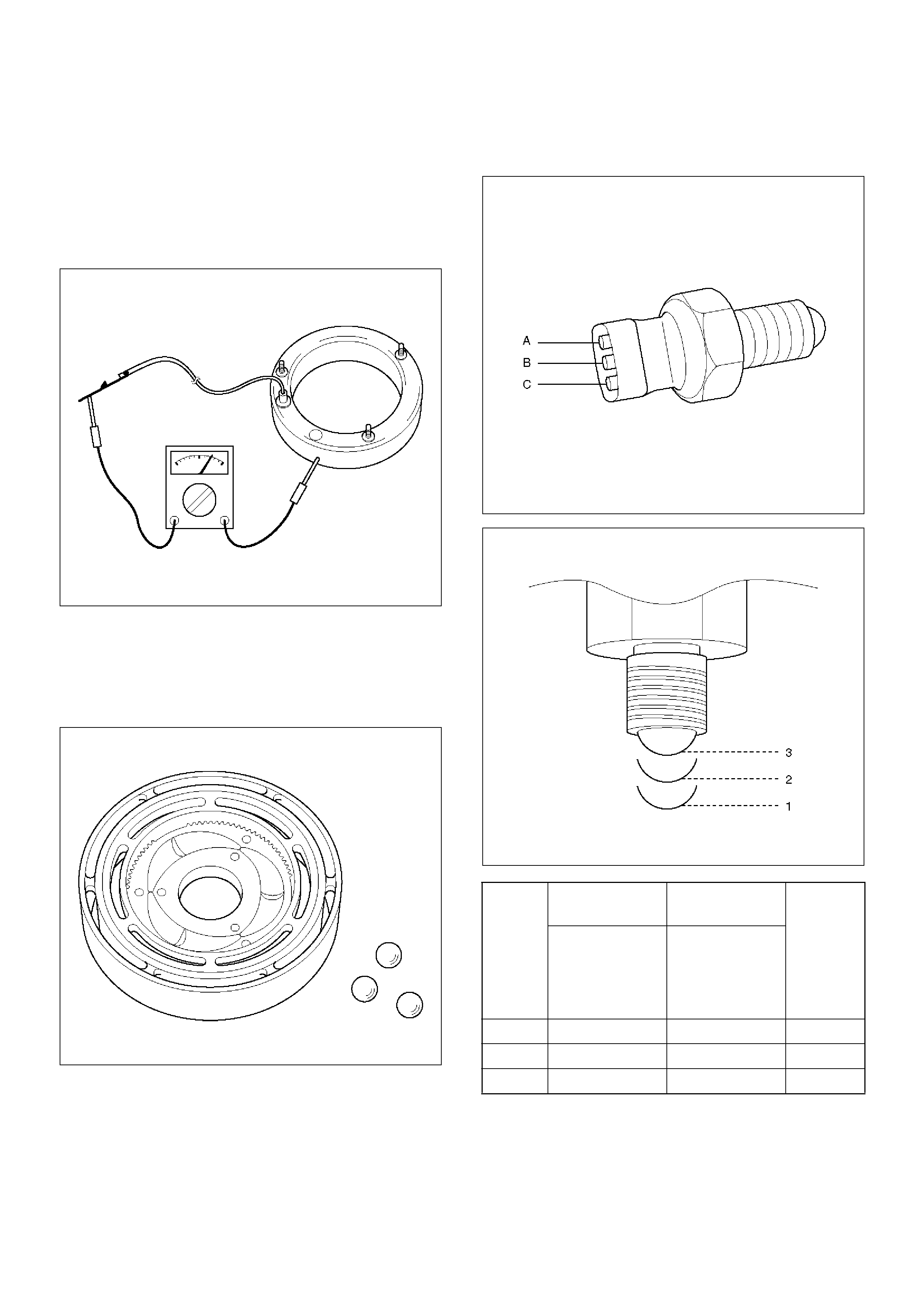
The Parts 4H and 4L Switch
• Check the continuity of 4H and 4L switch.
261RW003
261RW049
Switch
Stroke
4H Switch
Signal
4L Switch
Signal
The
correspo
nding
position
of
transfer
lever
B to Switch
Body
A to C
1 Open Open High
2 Open Close 4L
3 Close Close Neutral
Transfer Case
Disassembled View
265RW015
EndOFCallout
Reassembly
1. Remove the oil seal from the transfer case.
2. Apply engine oil to the circumference of the new oil
seal and fill the lip with grease (Besco L2 or
equivalent).
Legend
(1) Transfer Case
(2) Ball Bearing
(3) Ring Gear
(4) Snap Ring
(5) Input Shaft and Carrier Assembly
(6) Snap Ring
(7) Ball Bearing
(8) Snap Ring
(9) Thrust Plate
(10) Carrier Assembly
(11) Snap Ring
(12) Circular Hub
(13) Input Shaft
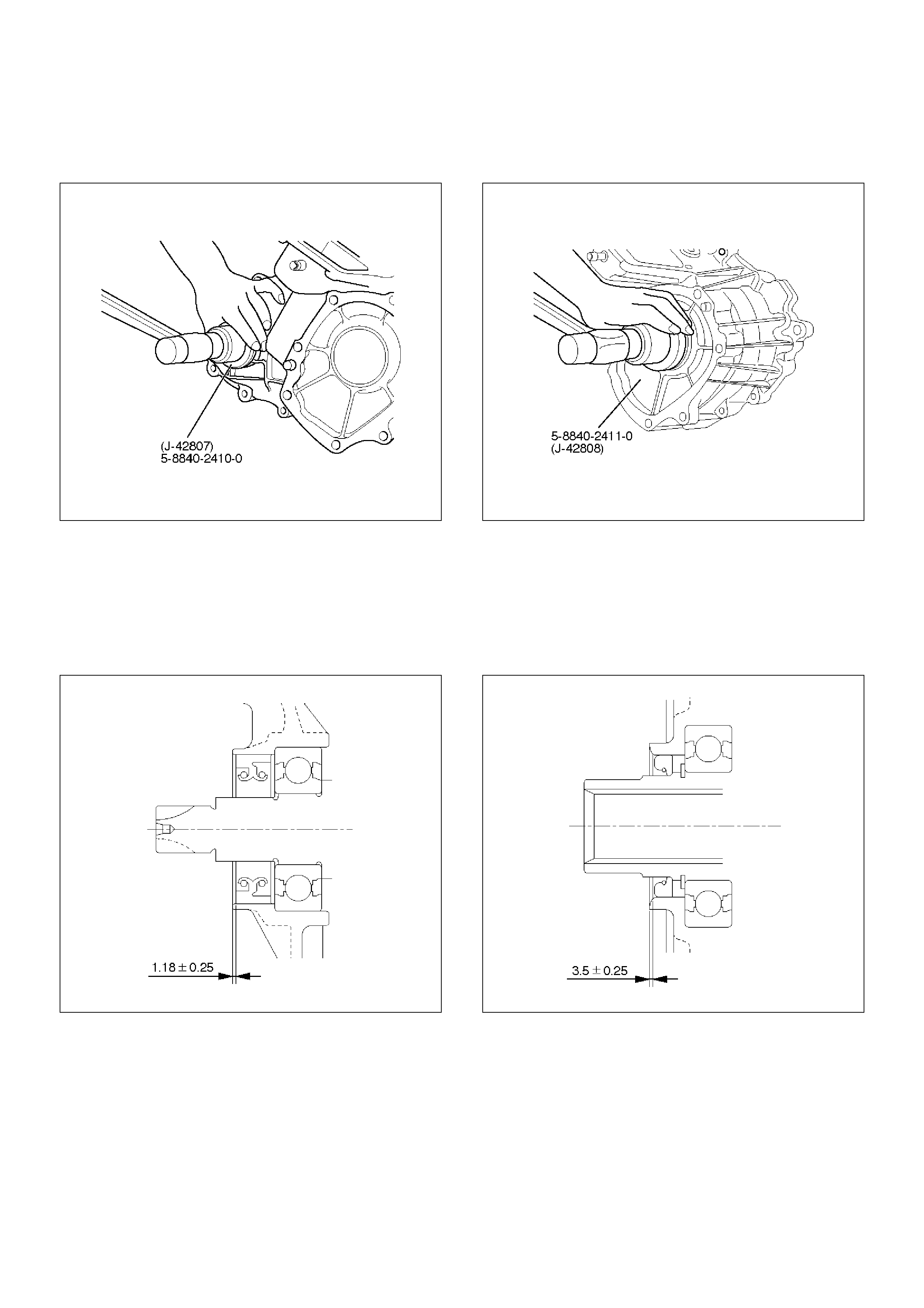
3. Using the front output shaft oil seal installer
5-8840-2410-0 (J-42807), install the oil seal to the
transfer case.
261RW053
Front Output Shaft Oil Seal
Distance between the transfer case end and oil seal.
NOTE: When installing the oil seal to the specified
dimension, be careful not to damage it.
Distance : 0.93—1.43mm(0.037—0.056in)
A04RW003
1. Using the input shaft (main) oil seal installer
5-8840-2411-0 (J-42808), install the oil seal to the
transfer case.
261RW055
Input Shaft Oil Seal
Distance between the transfer case end and oil seal.
NOTE: When installing the oil seal to the specified
dimension, be careful not to damage it.
Distance : 3.25—3.75mm(0.13—0.15in)
A04RW002
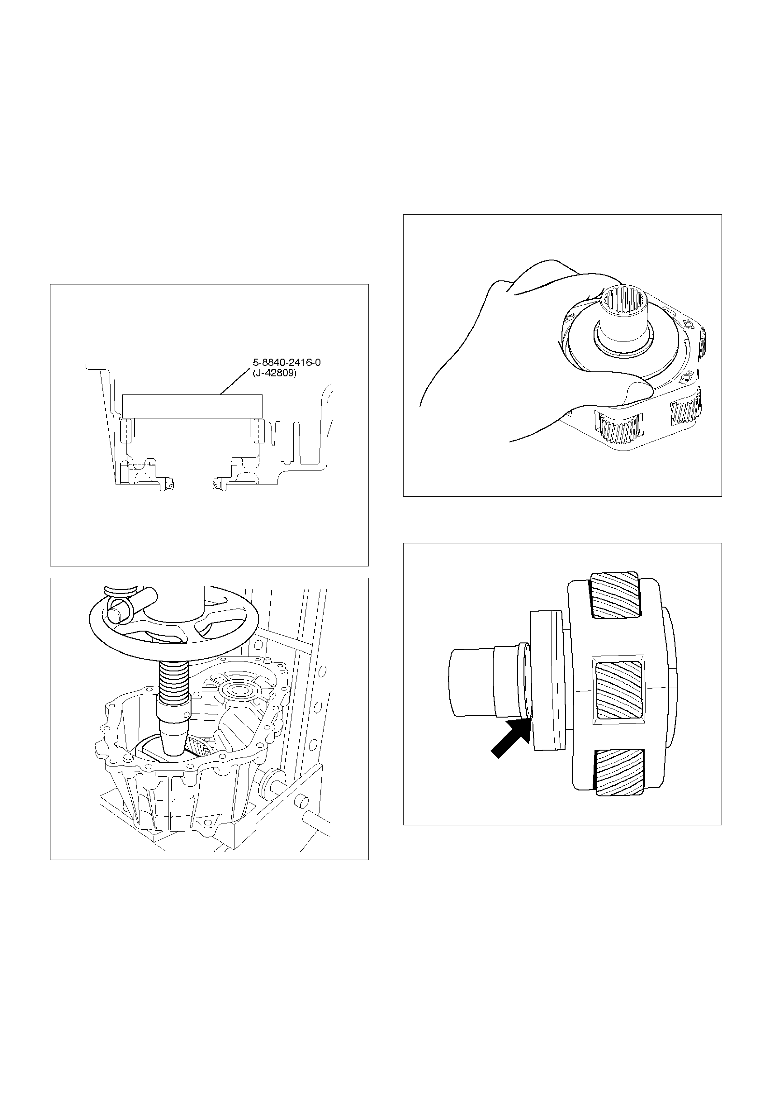
1. Using the installer 5-8840-2416-0 (J-42809),
press-fit the ring gear.
Pay attention to the following points.
• Identify the correct direction of gear.
• Do not damage the gear.
• Do not press-fit the ring gear slantingly.
• Press-fit the ring gear to the innermost.
• Remove burrs generated by press-fitting.
• If the transfer case has serrations, match them
with those of the gear and press-fit the gear.
261RW054
261RW034
2. Install the snap ring to the transfer case.
3. Install the circular hub.
4. Install the snap ring to the carrier.
5. Mount the carrier assembly to the input shaft.
6. Check the direction of thrust plate and mount it to
the input shaft.
265RW008
7. Mount the ball bearing to the input shaft so that the
snap ring will be installed to the input shaft.
265RW003
8. Install the snap ring to the input shaft.
9. Install the snap ring to the transfer case.
10. Using the snap ring pliers, expand the snap ring
through the opening between the ring gear and
carrier assembly and securely install the input shaft
and carrier assembly.
261RW038
11. Install the ball bearing (for front output shaft)
Output Shafts and Shift Control Shaft
Disassembled View
261RW010-1
EndOFCallout
Reassembly
1. Apply ATF to the inside of the ball bearing for the
front output shaft.
Legend
(1) Transfer Case Assembly
(2) Detent Spring
(3) Front Output Shaft
(4) Reduction Hub
(5) Output Shaft
(6) Reduction Fork Assembly
(7) Lock-up Shaft
(8) Spring Pin
(9) Reduction Fork
(10) Cam Assembly
(11) Snap Ring
(12) Washer
(13) Cam
(14) Cam Pilot Block
(15) Shifter Shaft Assembly
(16) Shifter Lever Shaft
(17) Snap Ring
(18) Reduction Lever Assembly
(19) Snap Ring
2. Mount the front output shaft to the transfer case.
266RW012
3. Install the shifter lever shaft to the transfer case
assembly.
4. Install the snap ring to the shifter lever shaft.
5. Install the reduction lever assembly to the shifter
lever shaft and fix the assembly with the snap ring.
261RW021
6. Install the cam to the cam pilot block.
7. Attach the washer to the cam pilot block and fix the
washer with the snap ring.
261RW029
8. Mount the reduction fork to the lock-up shaft.
9. Install the spring pin to the reduction fork and
lock-up shaft.
261RW020
10. Install the reduction fork assembly together with
reduction hub to the transfer case assembly.
261RW019
11. Install the cam assembly and tighten the cam pilot
block set bolts to the specified torque.
Torque : 12 N·m (1.2kg·m/104 lbin)
12. Tighten the detent spring to the specified torque.
Torque : 24 N·m (2.4kg·m/17lbin)
261RW022
13. Apply ATF to the needle bearing inside the input
shaft assembly.
14. Install the output shaft to the transfer case
assembly.
Sprocket and Mechanical Lock
Disassembled View
266RW008
EndOFCallout
Reassembly
1. Connect the hose and strainer to the oil pump
assembly.
2. Install the oil pump assembly to the output shaft and
set the magnet to the strainer position.
3. Install the thrust washer.
4. Install the spring to the lock-up fork.
5. Install the lock-up sleeve together with the lock-up
fork to the output shaft and lock-up shaft assembly.
Legend
(1) Strainer
(2) Hose
(3) Oil Pump Assembly
(4) Thrust Washer
(5) Mechanical Lock Hub
(6) Lock-up Sleeve
(7) Lock-up Fork
(8) Chain
(9) Lower Drive Sprocket
(10) Front Tone Wheel
(11) Drive Sprocket
(12) Sprocket Spacer
Legend
6. Install the spring retainers to the lock-up fork.
261RW018
7. Install the mechanical lock hub.
8. Apply ATF to the chain.
9. Engage the chain to both sprockets.
10. Install the chain and sprocket assembly to both
output shafts.
266RW010
11. Install the front tone wheel and sprocket spacer.
Clutch Pack and Clutch Cam
Disassembled View
266RW006
EndOFCallout
Reassembly
1. Mount the clutch pack assembly to which the multi
plate disk clutch is already installed to the output
shaft.
NOTE: Mount the clutch pack assembly while adjusting
the phase of both the clutch housing and drive sprocket.
2. Install the insulator washer.
3. Install the armature plate.
Legend
(1) Clutch Pack Assembly
(2) Insulator Washer
(3) Armature Plate
(4) Snap Ring
(5) Wave Spring
(6) Cam Pulley
(7) Cam Ball
(8) Cam and Coil Housing
(9) Thrust Bearing
Legend
4. Using snap ring pliers, install the snap ring.
266RW009
5. Install the wave spring.
6. Install the cam pulley.
7. Place a ball on each groove of the cam pulley.
266RW013
8. Install the cam and coil housing.
9. Install the thrust bearing.
Main Data and Specifications
Leading Particulars
Torque Specifications
E04RW012
Type Transfer case with low range reduction mechanism
2H Rear wheel drive
TOD Electronically controlled torque split four wheel drive
4L Low-speed mechanical lock-up four wheel drive
Control system Floor direct control
Gear ratio H 1.000
L 2.480
Oil quantity 1.9 litres
Oil ATF DEXRON®-III
E04RW013
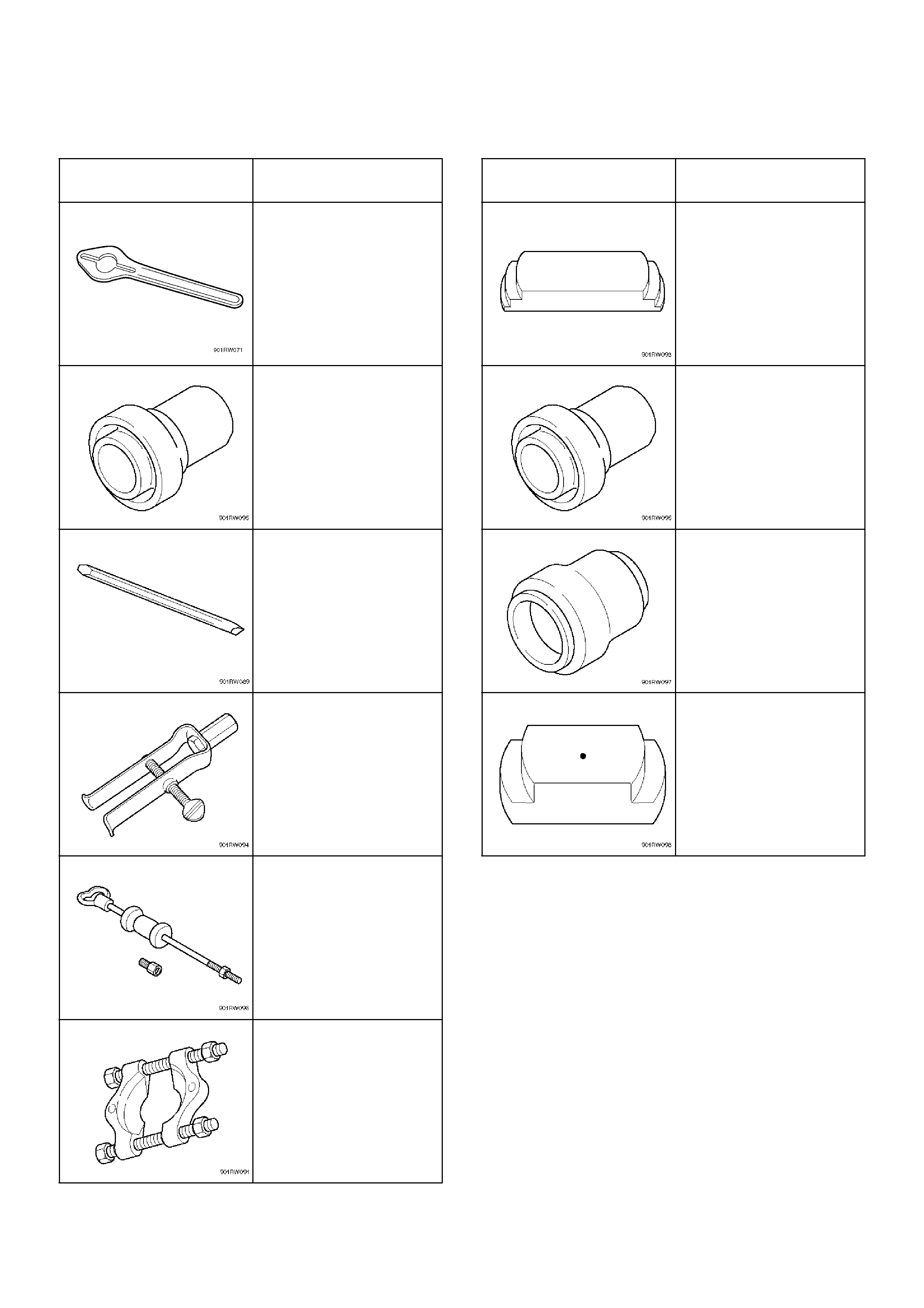
Special Tools
ILLUSTRATION TOOL NO.
TOOL NAME
5–8840–0133–0
(J–8614–11)
Flange Holder
5–8840–2412–0
(J–42804)
Rear Oil Seal Installer
5–8840–2293–0
(J–39209)
Punch
5–8840–2409–0
(J–42805)
Bearing Remover
5–8840–0084–0
(J–2619–01)
Slide Hammer
5–8840–0015–0
(J–22912–01)
Bearing Remover
ILLUSTRATION TOOL NO.
TOOL NAME
5–8840–2413–0
(J–42806)
Ring Gear Replacer
5–8840–2410–0
(J–42807)
Front Out Oil Seal
Installer
5–8840–2411–0
(J–42808)
Input Shaft Oil Seal
Installer
5–8840–2416–0
(J–42809)
Ring Gear Installer