
SECTION 7E1 - TOD TRANSFER CASE CONTROL
Service Precaution
General Description
System Components
Parts Location
Functions of Indicator Lamp
Diagnosis
Basic Diagnostic Flow Chart
Parts Location
Parts Location - 6VE1
Parts Location - 4JX1
Circuit Diagram
Circuit Diagram - 6VE1
Circuit Diagram - 4JX1
Connector List
Checking Failed Pin
Checking Failed TOD Control Unit Pin
Tech 2 Scan Tool
Using TECH 2 On The Vehicle
Connecting TECH 2 To The Vehicle
Chassis Application Menu Torque On Demand (TOD)
TOD TECH 2 Functions
Diagnosis from Trouble Codes
Trouble Diagnosis Depending on The Status of TOD
Indicator
Diagnosis from Symptom
Service Precaution
WARNING: IF SO EQUIPPED WITH A
SUPPLEMENTAL RESTRAINT SYSTEM (SRS),
REFER TO THE SRS COMPONENT AND WIRING
LOCATION VIEW IN ORDER TO DETERMINE
WHETHER YOU ARE PERFORMING SERVICE ON
OR NEAR THE SRS COMPONENTS OR THE SRS
WIRING. WHEN YOU ARE PERFORMING SERVICE
ON OR NEAR THE SRS COMPONENTS OR THE SRS
WIRING, REFER TO THE SRS SERVICE
INFORMATION. FAILURE TO FOLLOW WARNINGS
COULD RESULT IN POSSIBLE AIR BAG
DEPLOYMENT, PERSONAL INJURY, OR
OTHERWISE UNNEEDED SRS SYSTEM REPAIRS.
CAUTION: Always use the correct fastener in the
proper location. When you replace a fastener, use
ONLY the exact part number for that application.
HOLDEN will call out those fasteners that require a
replacement after removal. HOLDEN will also call
out the fasteners that require thread lockers or
thread sealant. UNLESS OTHERWISE SPECIFIED,
do not use supplemental coatings (Paints, greases,
or other corrosion inhibitors) on threaded fasteners
or fastener joint interfaces. Generally, such
coatings adversely affect the fastener torque and
the joint clamping force, and may damage the
fastener. When you install fasteners, use the correct
tightening sequence and specifications. Following
these instructions can help you avoid damage to
parts and systems.
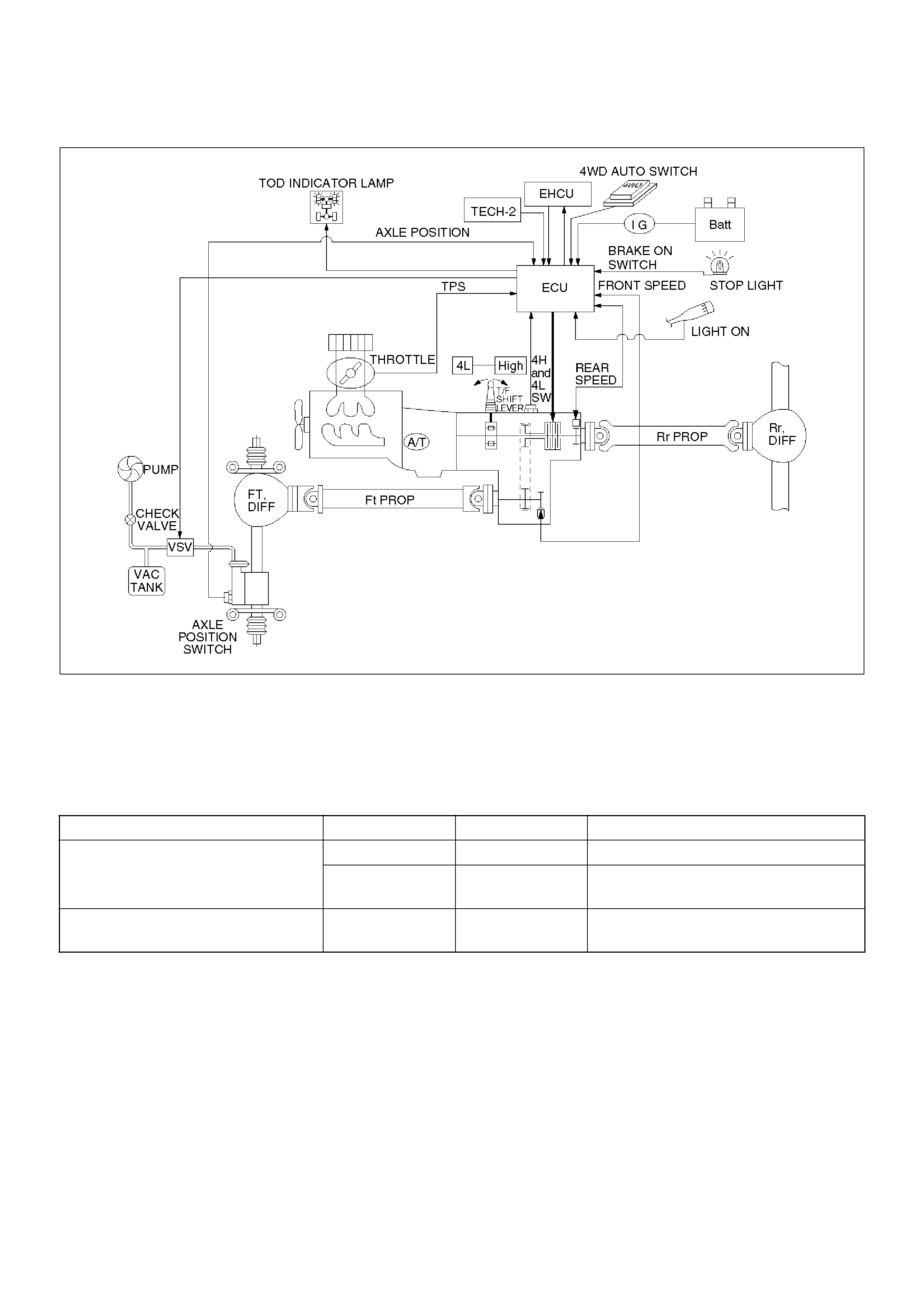
General Description
C07RW014-1
TOD (Torque on Demand) system is traction state
control system to vehicle.
Transfer Position and Drive Mode
Three drive modes can be selected through operation of
4WD AUTO switch and transfer lever.
The electronic control unit (ECU) judges the signals
from the transfer lever and 4WD AUTO switch, and
controls the transfer drive mode and shift-on-the-fly
system status.
TOD Control
The TOD position usually drives the rear wheels, and
transmits the torque to the front wheels with the help of
electronically controlled torque split mechanism
according to running conditions encountered. The
driving force is directly transmitted to the rear wheels.
This force is split by the transfer and delivered to the
front wheels. The magnitude of the torque transmitted
to the front wheels is controlled by changing the
pressing force of the multi plate disk clutch built in the
transfer unit. The pressing force of the clutch is
controlled by changing the duty cycle to the
electromagnetic coil mounted to the rear of the clutch.
When the clutch is completely disengaged, the rear
wheels are driven. When the clutch is completely
engaged, a rigid four wheel drive mode is obtained. The
torque split status is controlled continuously between
the rear wheel and four wheel drive modes. This
system includes front and rear speed sensors, and
receives throttle position sensor information from ECM.
The control unit receives signals sent from these
sensors and changes the pressing force of the multi
plate disk clutch to determine the torque distribution on
the front and rear wheels. Therefore, when the slip of
Transfer Position 4WD AUTO SW Mode Drive mode
HIGH ON (NORMAL) 2H Rear wheel drive
OFF (PUSHED) TOD Electronically controlled torque split
four wheel drive
4L ON/OFF 4L Low-speed mechanical lock-up four
wheel drive

the rear wheels is increased against the current torque
level in the normal rear wheel drive mode, the control
unit detects the slip condition, determines the optimum
torque based on the feedback control logic, and
increases the torque to the front wheels.
The control unit uses the signal from the throttle position
sensor to predict the future vehicle condition and the
intention of the driver with respect to acceleration and
deceleration, and determines the initial torque
distribution using these data and the information from
the speed sensors.
In case of small circle turning in the parking lot, for
example, the control unit minimizes the clutch pressing
force to restrict a braking fault. When the ABS becomes
active, the control unit optimizes the clutch pressing
force to ensure stable braking.
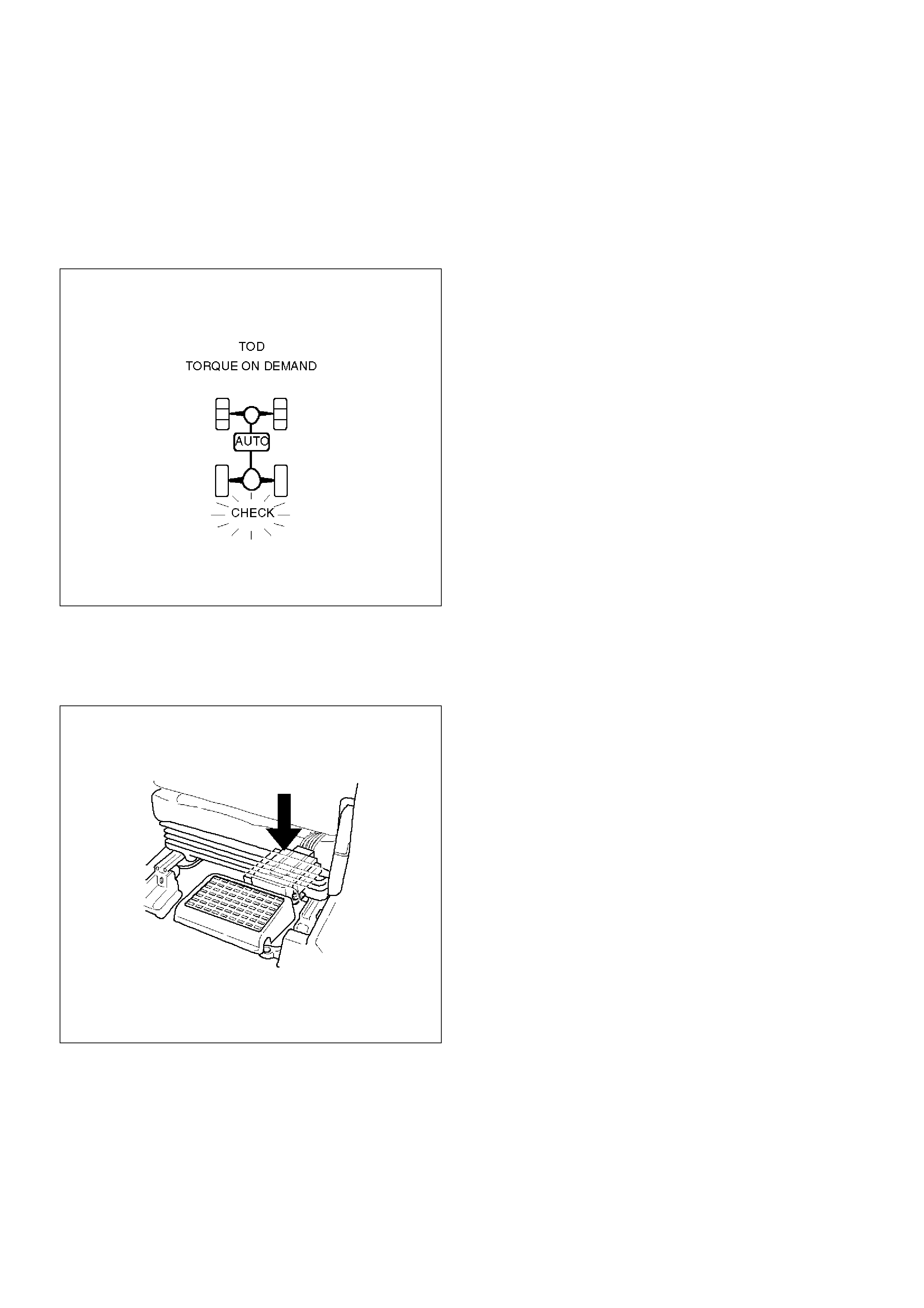
TOD Indicator Control
The TOD indicator on the instrument panel informs the
driver of the current working status of the transfer unit.
The information consists of two items: the drive mode
(2H, TOD, 4L, transition) and the torque split status of
the TOD (torque distribution level). The indicator can
display occasional errors and corresponding error
codes.
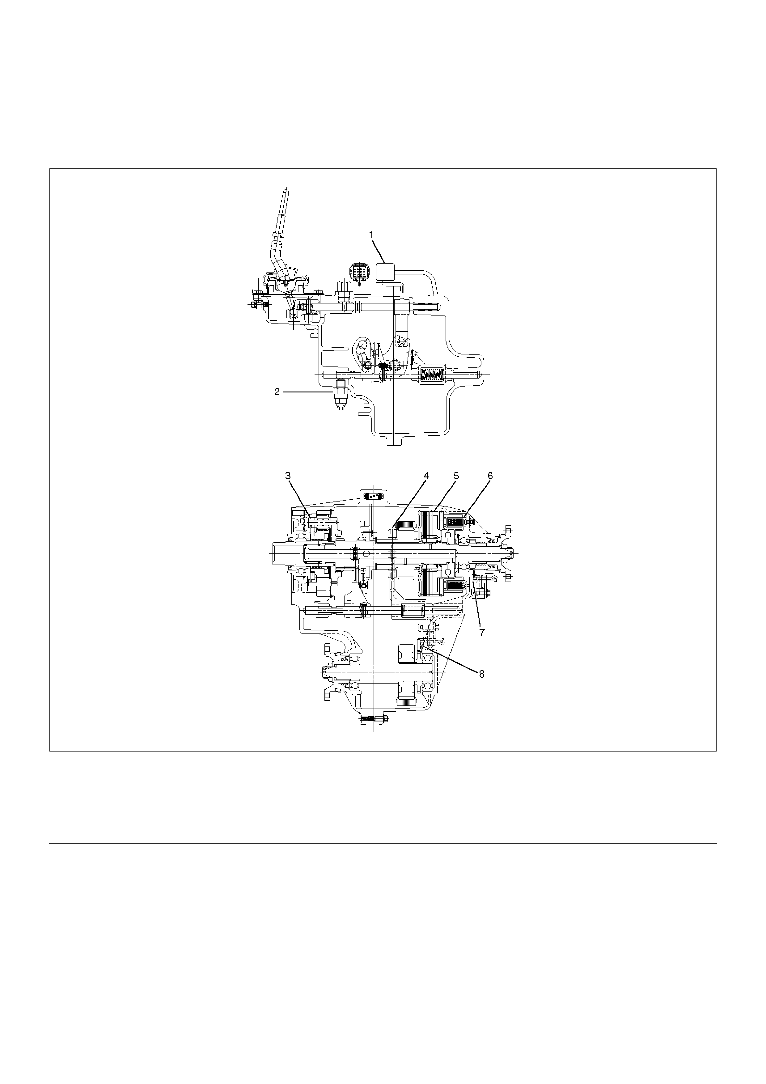
System Components
Parts Location
A07RY00002
EndOFCallout
Legend
(1) T/F Connector
(2) 4H and 4L Switch
(3) High-Low Planetary Gear Set
(4) Mechanical Lock
(5) Multi Plate Disk Clutch Pack
(6) Electromagnetic Coil
(7) Rear Speed Sensor
(8) Front Speed Sensor
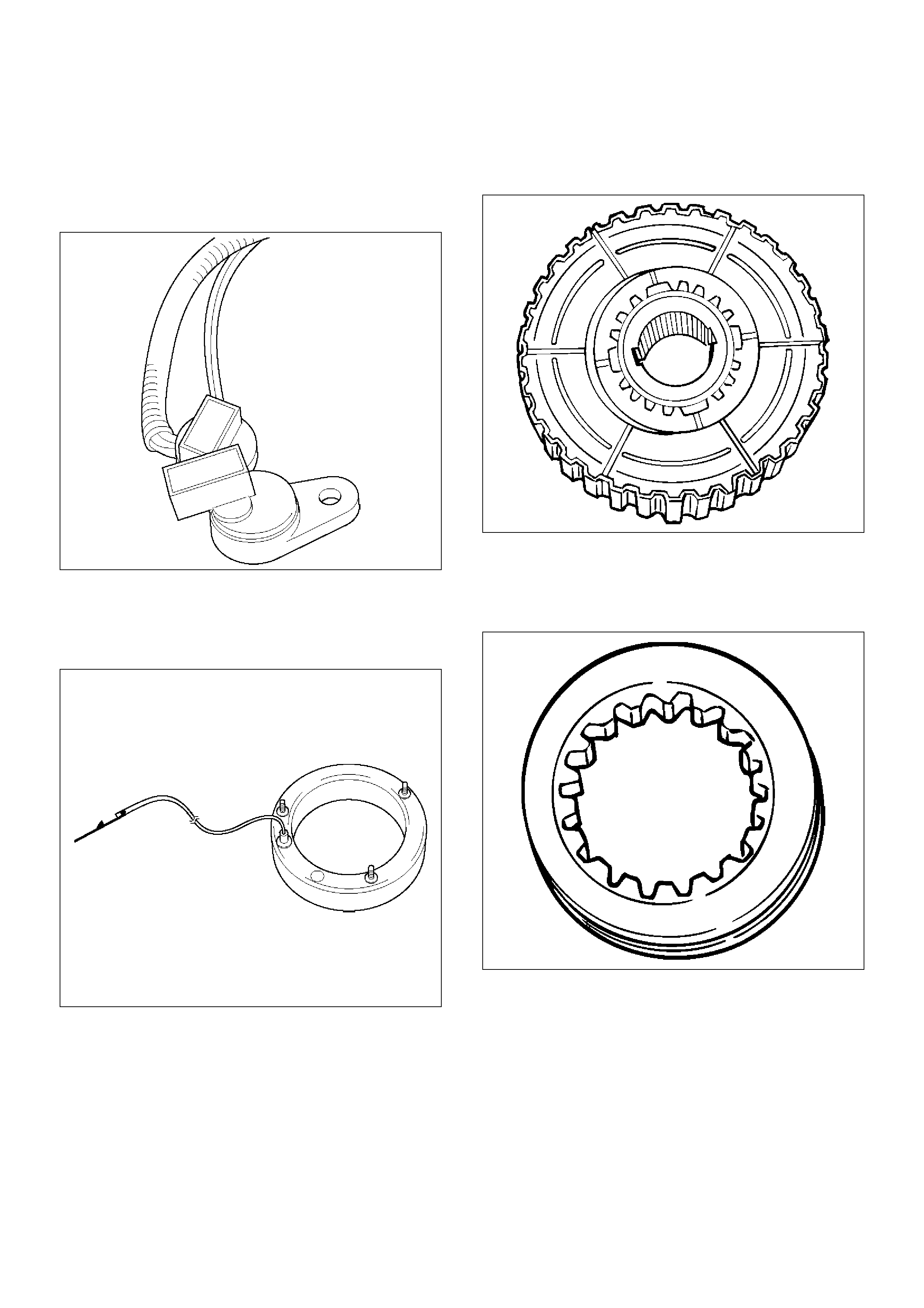
Front and Rear Speed Sensors
The sensors are built in the transfer case, detect the
rotation of rotors directly coupled to the propeller shafts.
Thirty rectangular pulses are output per one rotation of
the propeller shaft.
261RW045
Electromagnetic Coil
Receives the duty signals from the TOD control unit and
controls the pressing force of the clutch pressure cam.
261RW044
Multi Plate Disk Clutch Pack
Transmits the torque determined by the clutch pressing
force to the front propeller shaft via the front drive chain.
262RW029
Mechanical Lock Sleeve
Couples the front and rear propeller shaft mechanically
when the transfer shaft is in the 4L position.
262RW028
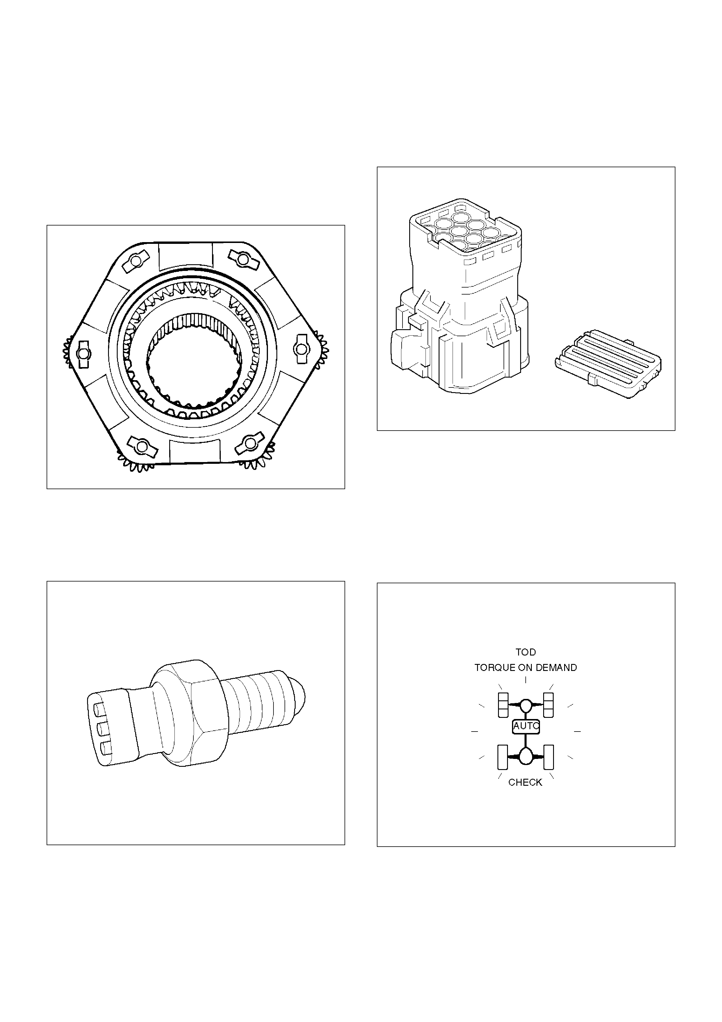
High-Low Planetary Gear Set
Establishes an auxiliary transmission mechanism.
When the transfer shift lever is set to the 2H or TOD
position, the reduction gear ratio is 1.000 and the
corresponding driving force is generated. When the
transfer shift lever is set to the 4L position, the reduction
gear ratio is 2.480 and the corresponding driving force
is generated.
262RW030
4H and 4L Switch
Detects the shift position of the transfer from the
movement of the transfer lever and outputs signals to
the TOD control unit.
261RW002
Transfer Connector
Transmits the input and output signals of the speed
sensors, electromagnetic coil, and 4H and 4L switche to
the vehicle harness. A waterproof 12-pin type is used.
261RW046
TOD Indicator Lamps (on the instrument
panel)
Inform the following items.
• Bulb check
• Drive mode
• ABS IN status
• BRAKE ON status
821RW049
Check Lamp
Inform the following items.
• Bulb check
• Fail (fail alarm)
•Trouble code
• Diesel/gasoline MAP
821RW078
TOD ECU
This control unit is mounted to the front right hand seat
via a special bracket.
F07RW029
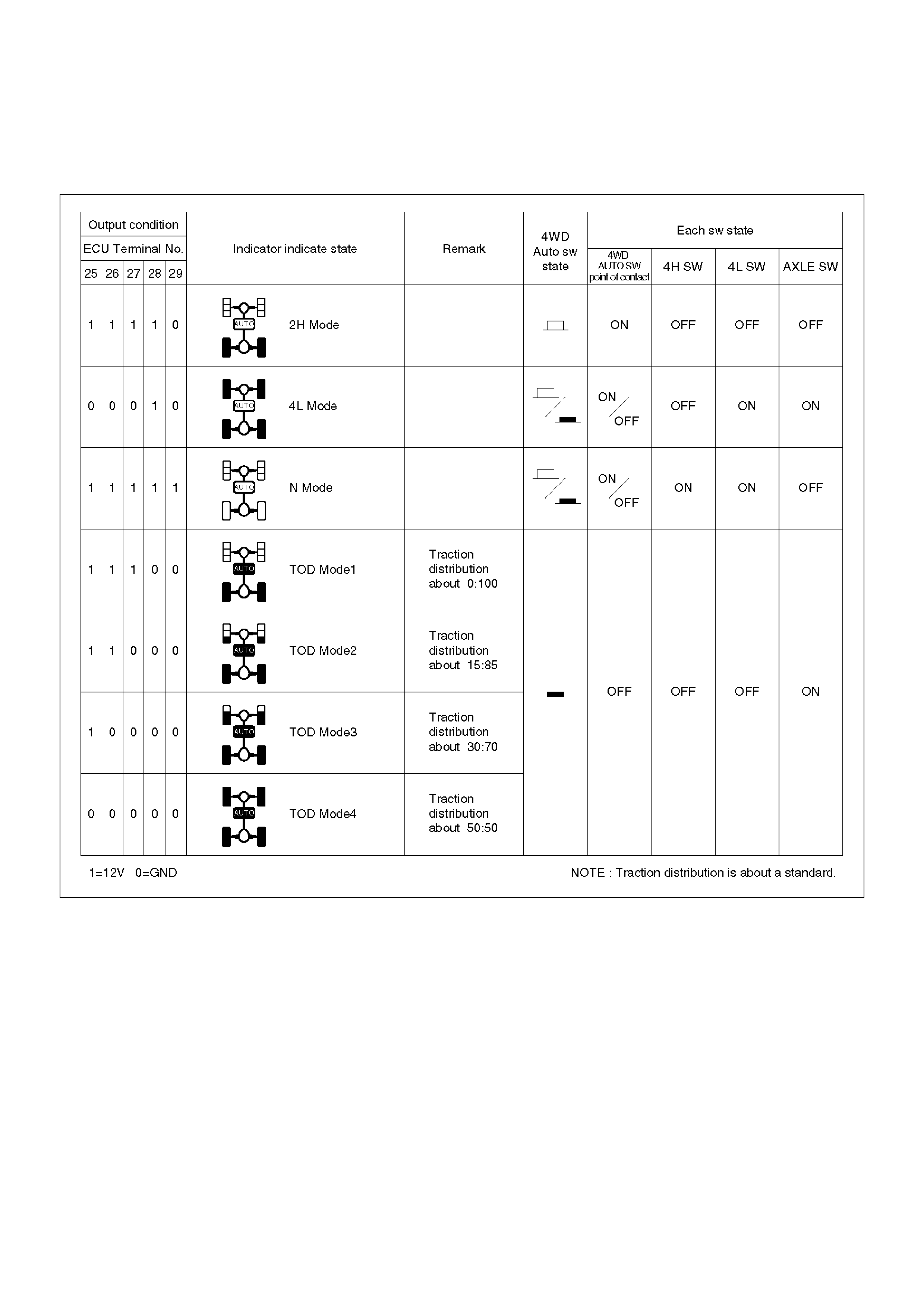
Functions of Indicator Lamp
TOD Indicator Lamps
C04RY00014
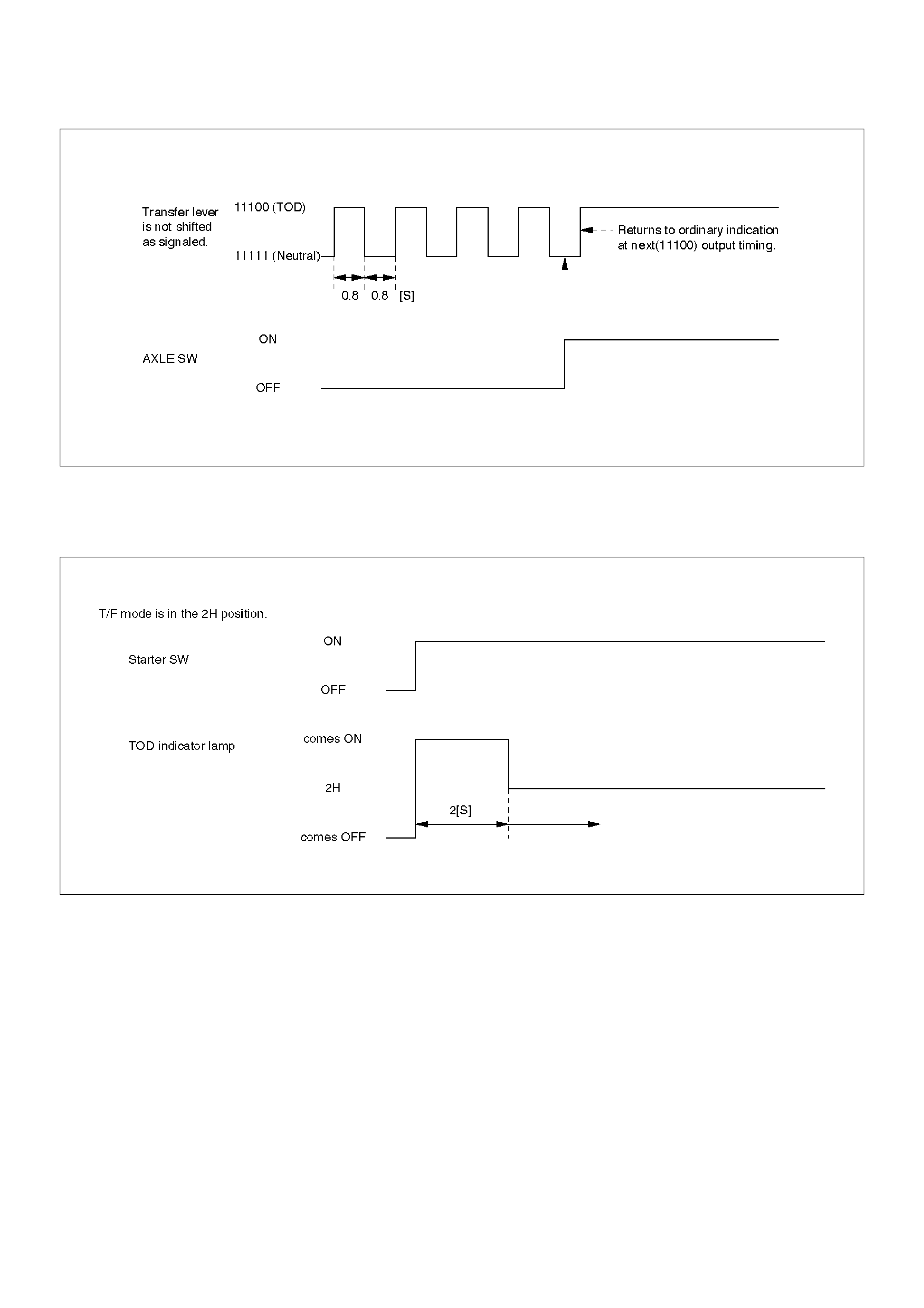
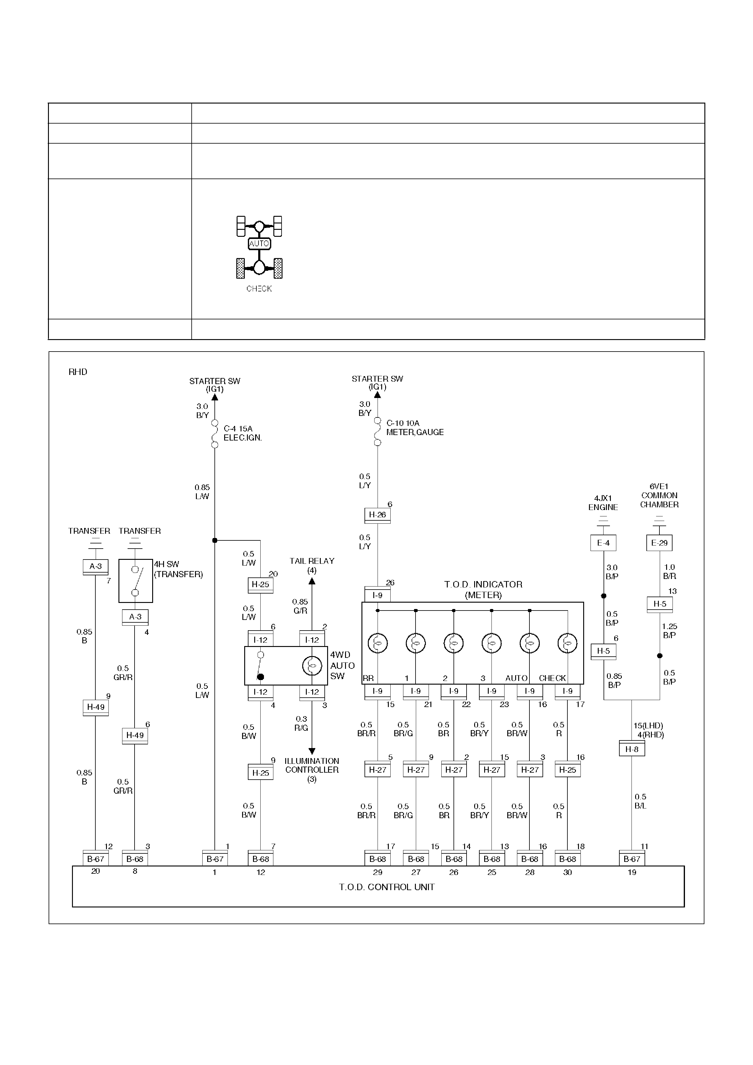
Indication During Transition of Transfer Lever
When the 4WD AUTO SW is selected or the transfer
lever is shifted, and the signals from the AXLE switch do
not comply with the signal conditions of the 4H and 4L
switch, the transfer lever position signals generated by
the 4H and 4L switch and the N position signals are
repeatedly output at an interval of 0.8 second.
NOTE: After the 4WD AUTO SW and the transfer lever
is set to the specified position and the AXLE switch
generates compliant signals, the normal output status is
returned.
C07RW061
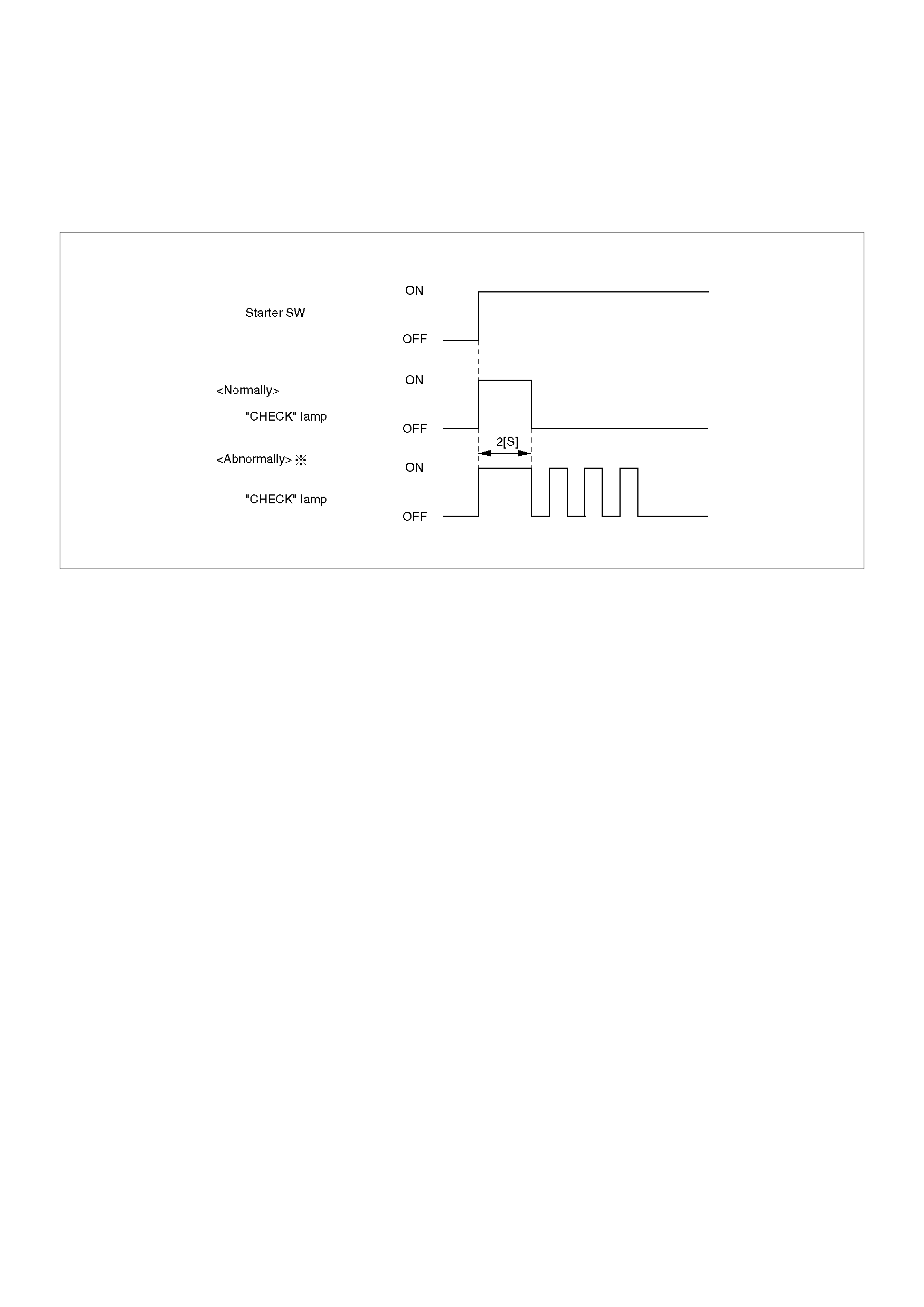
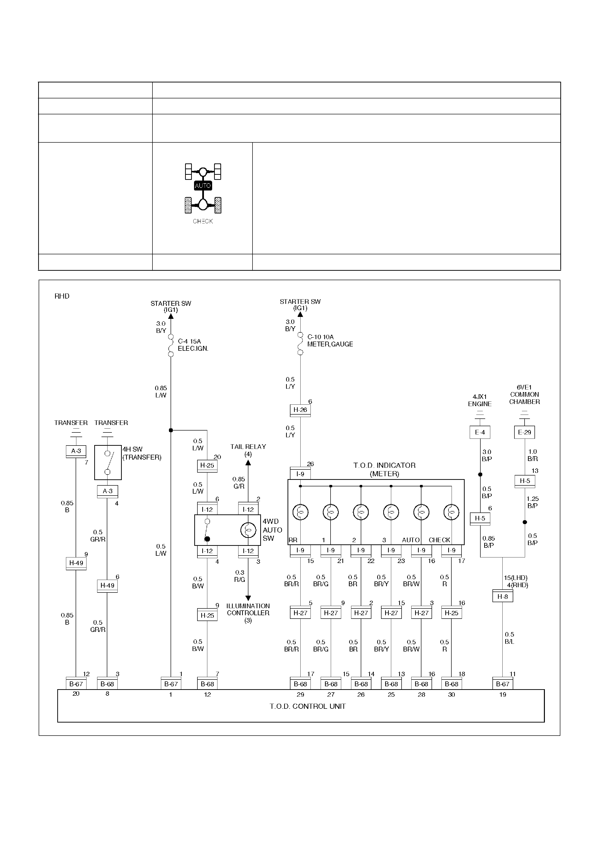
Bulb Check
When the starter switch is turned on, the TOD indicator
lamps go on as shown below.
NOTE: Once the starter switch is turned on, all the TOD
indicator lamps are lit for two seconds even if the
transfer lever is in any position.
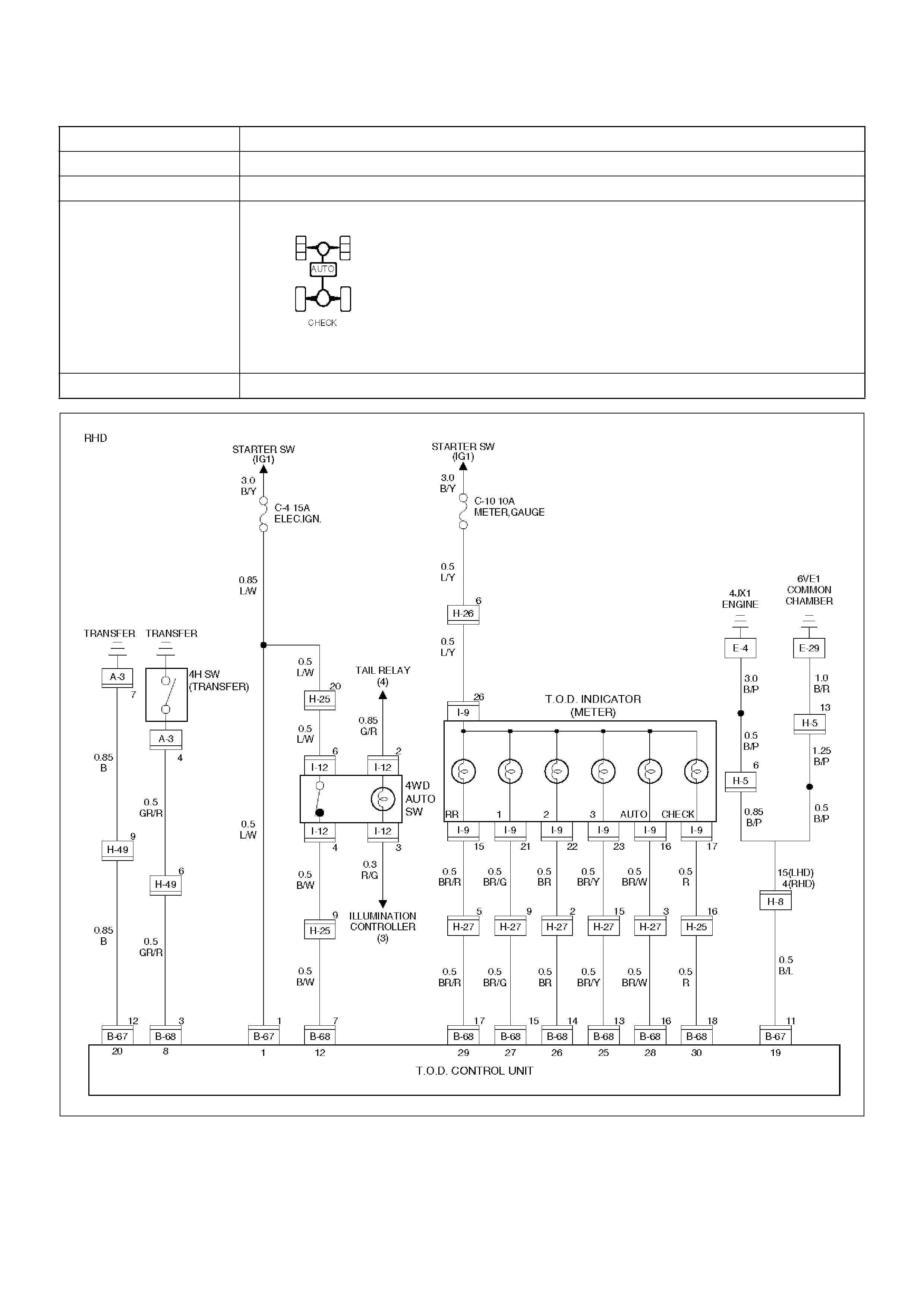
C07RW016
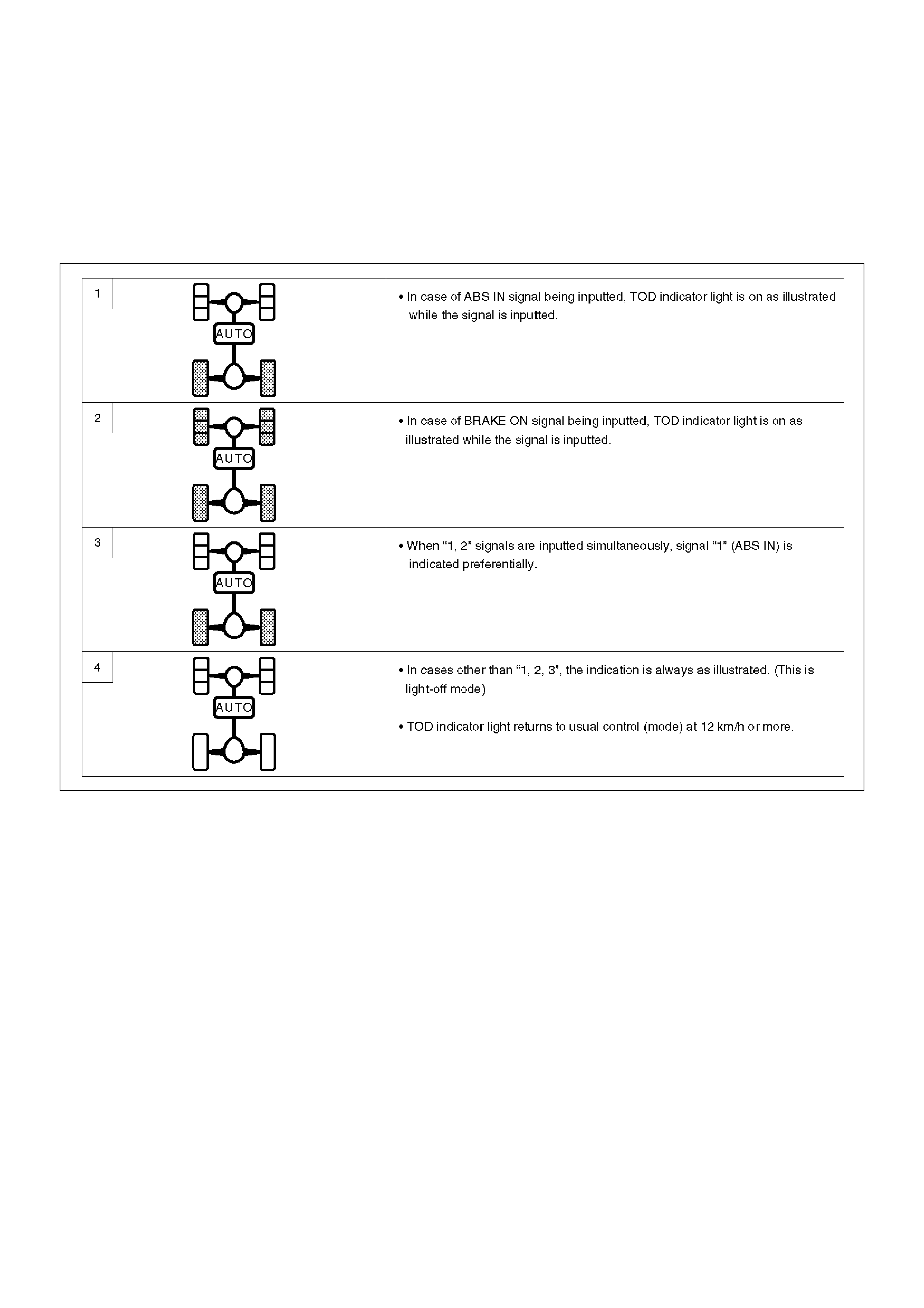
Simplified checking method of ABS IN and BRAKE ON signals:
In the event that any of the signal inputs listed below are
observed while the self-diagnostic code is being
displayed (the self-diagnostic connector is
short-circuited to GND), you can simply check the ABS
IN and BRAKE ON signals as shown in the figures
below.
C07RW017
Check Lamp
Check Lamp Bulb Check
When the starter switch is turned on in the normal state,
the control unit turns on the CHECK lamp to check the
bulb.
C07RW019
The CHECK lamp also has the following functions.
D-G MAP recognition and display (The control unit
displays what type of vehicle, diesel or gasoline
vehicle, it recognizes.)
1. Short-circuit the self-diagnostic connector.
2. Turn on the starter switch. (Displays with respect to
the self-diagnosis begin to appear.)
NOTE: Do not start the engine.
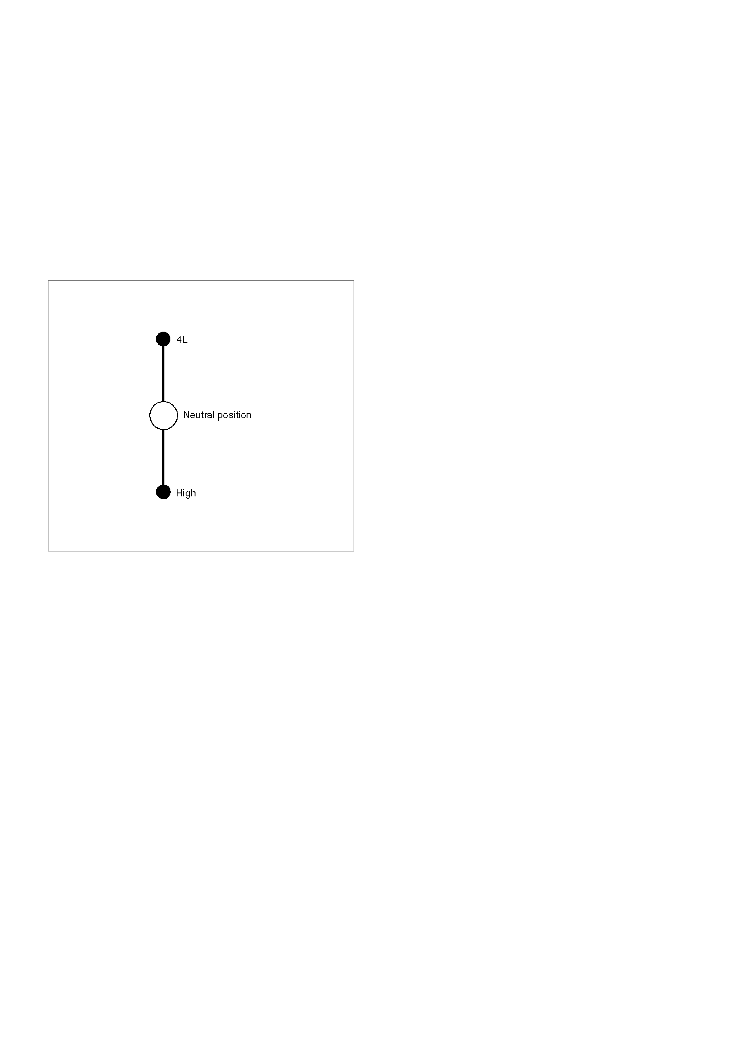
3. Shift the transfer lever to the neutral position
between HIGH and 4L.
4. After all the conditions in 1 through 3 above are met,
set the throttle to the WOT (wide open throttle)
position (i.e., full open position). The display of the
self-diagnosis is temporarily suspended, and the
CHECK lamp begins to display that MAP is
recognized by the TPS (throttle position sensor)
according to the current conditions.
NOTE: If the TPS has failed, this function might not
work.
1 When the control unit recognizes the vehicle as
gasoline type, the CHECK lamp is turned on for
five seconds and this mode is repeated at an
interval of 0.3 second.
2 When the control unit recognizes the vehicle as
diesel type, the CHECK lamp is turned off for
five seconds and this mode is repeated at an
interval of 0.3 seconds.
3 Upon completion of step 4, the system resumes
the self-diagnosis. (The self-diagnosis is
executed from the beginning.)
5. Turn off the starter switch once. When above
conditions are met again in the future, the TPS MAP
control can be started.
C04RW010
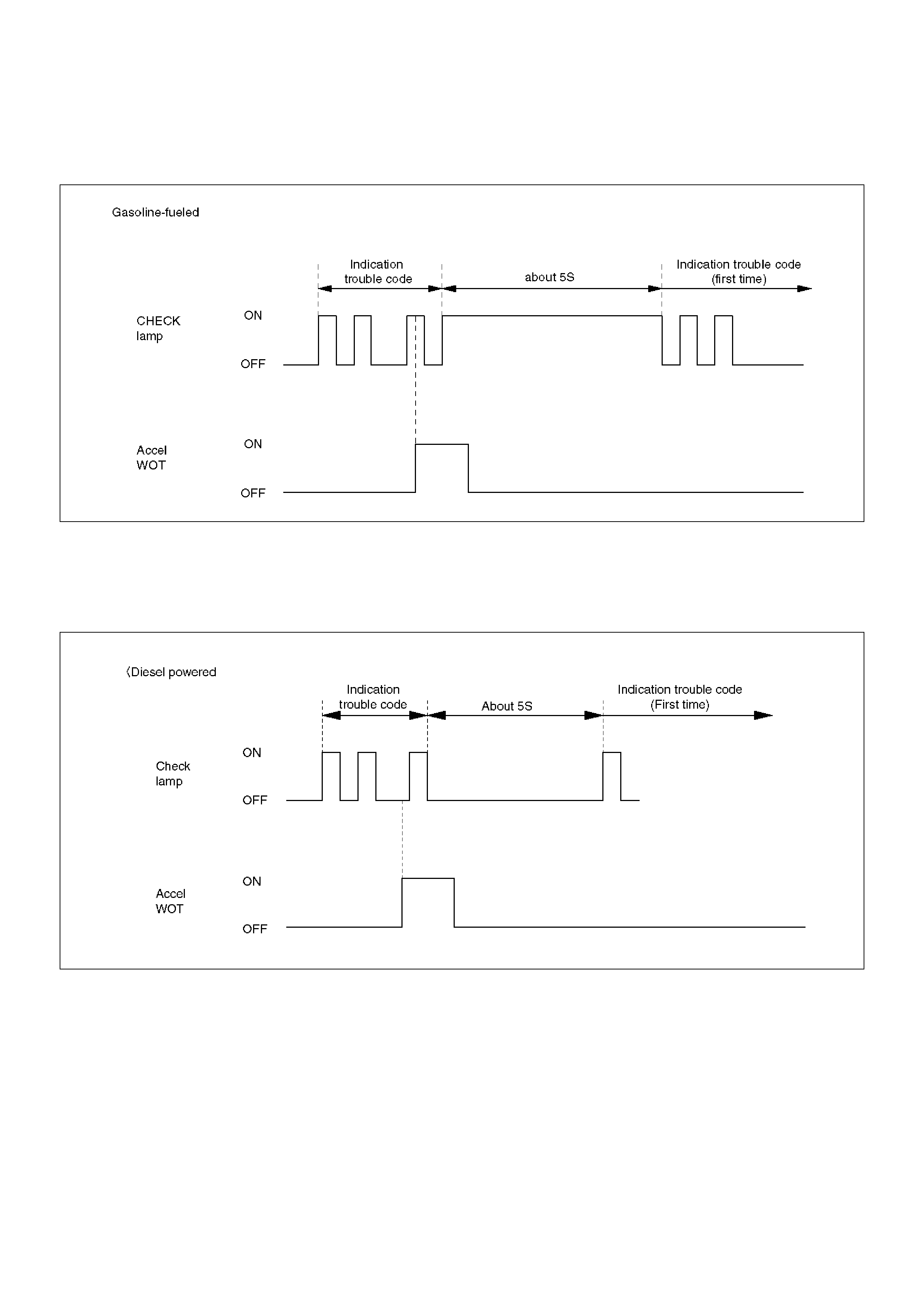
If the accelerator wide-open-throttle(WOT) timing check
lamp is on, the subsequent timing will display
immediately after the WOT timing check lamp turns off.
If the WOT timing check lamp is off, the subsequent
lamp timing will display immediately.
C04RY00011
If the WOT timing check lamp is off, the subsequent
timing will display immediately after the WOT timing
check lamp turns on.
If the WOT timing check lamp is on, the subsequent
lamp timing will display immediately.

Diagnosis
General Information Diagnosis
The troubles on TOD are classified into the group that
can be identified by the lighting status of the TOD
indicator lamps and those that can be recognized as
abnormal phenomena of the vehicle by the driver.
The troubles that can be identified by the lighting status
of the TOD indicator lamps are examined by the
procedures “Diagnosis from Trouble Codes”
and“Trouble Diagnosis Depending on The Status of
TOD indicator”. The troubles that can be recognized as
abnormal phenomena of the vehicle by the driver are
examined by the procedure“Diagnosis from symptom”.
Self-diagnosis
The control unit has a function of self-diagnosis. If a
trouble occurs in the course of system startup, the
control unit blinks the CHECK lamp and saves the
trouble code.
C07RW021
NOTE: If an intermittent fault occurs, the control unit
stops blinking upon removal of the fault. The trouble
code is saved to the control unit.
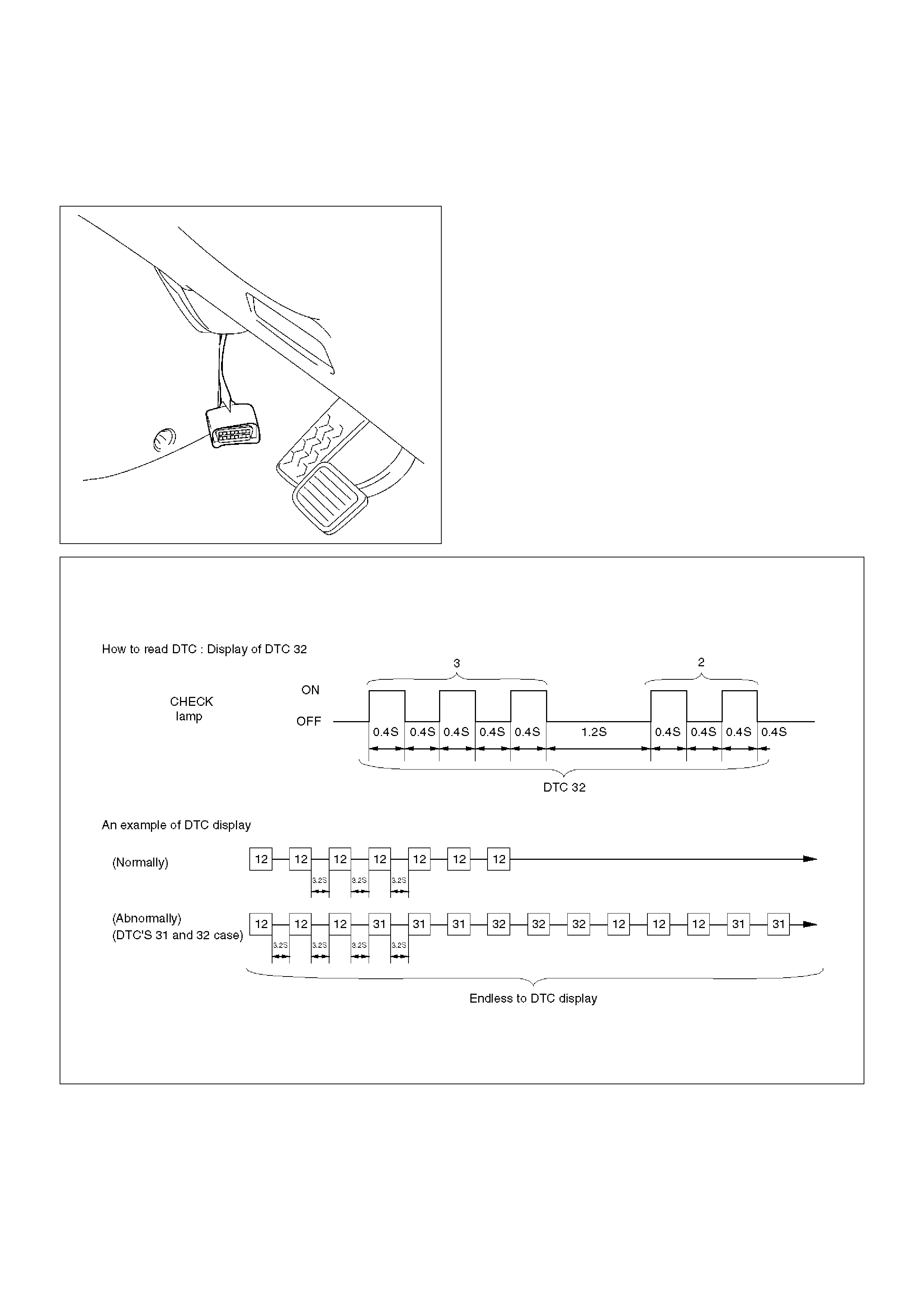
Indication Method of Trouble Code
• Short-circuit terminal 8 of the self-diagnostic
connector to GND to display the trouble code on the
CHECK lamp.
810RW308
• If no trouble codes exist, code “12” is displayed
continuously.
• If trouble codes exist, code “12” is displayed three
times, and the trouble codes, starting from the
smaller code number, are displayed three times
respectively.
C07RW013
How to Clear The Trouble Code
The trouble codes saved to the control unit can be
deleted by the following procedure if the starter switch is
being in the OFF position.
1. Shift the transfer lever to the neutral position
between HIGH and 4L, and short-circuit the
self-diagnostic connector.
NOTE: The neutral position between HIGH and 4L
refers to the point that turns off the TOD indicator lamps.
(However, be sure to check the position before
short-circuiting the self-diagnostic connector.)
C07RW011
2. Turn on the starter switch while maintaining the
state of step 1, and step on the brake pedal five
times within five seconds from the first step on.
(Note that “five times” includes the first step on).
(The TOD indicator lamps display the 4L mode
whenever the brake pedal is stepped on.)
3. If the conditions shown in steps 1 and 2 are met, the
trouble codes saved to the control unit are cleared.
(After the codes are completely deleted, the code 12
that indicates the normal condition is continuously
displayed.)
Precautions on Diagnosis
Replacement of Control Unit
The control unit itself rarely fails. In most cases, the
harnesses have failed (i.e. short-circuit) to cause
secondary troubles. Other cases include that the cause
has been unknown due to intermittent occurrence of
troubles and the troubles are removed accidentally
along with replacement of control unit, resulting in
misjudgment of cause. Therefore, before replacing the
control unit, check the connector joints and whether the
unspecified current flows in the control unit due to
short-circuit between harnesses.
Intermittent Failures
Troubles which are intermittently observed are mostly
attributable to temporary imperfect connection of
harnesses and connectors.
When such troubles are found, check the associated
circuit according to the following procedure.
1. Check whether improper connectors are plugged in
or connector terminals are completely engaged.
2. Check whether the terminals are deformed or
damaged. If yes, remove the deformation or
damage and connect the terminals securely.
3. It is likely that wires in the harness are falsely
broken. Therefore, in examination of failed harness
circuit, shake the harness for check to such extent
that the harness will not be damaged.
Test Run of Failed TOD Vehicle
If the TOD indicator lamps experienced faulty operation
even once in the past, the failed portion can be
identified by use of the procedure “Diagnosis from
Trouble Codes” or “Trouble Diagnosis Depending on
The Status of TOD Indicator”. If the troubles that are
only recognized as abnormal phenomena of the vehicle
by the driver are observed, conduct the test run in the
following procedure to reproduce the faulty phenomena
and diagnose the fault for each fault.
1. Start the engine, and check that the TOD indicator
lamps are turned on for about two seconds for initial
check; the CHECK lamp goes off; and the TOD
indicator lamps display the specified drive mode. (If
the CHECK lamp starts blinking, read the trouble
codes and identify the failed portion.)
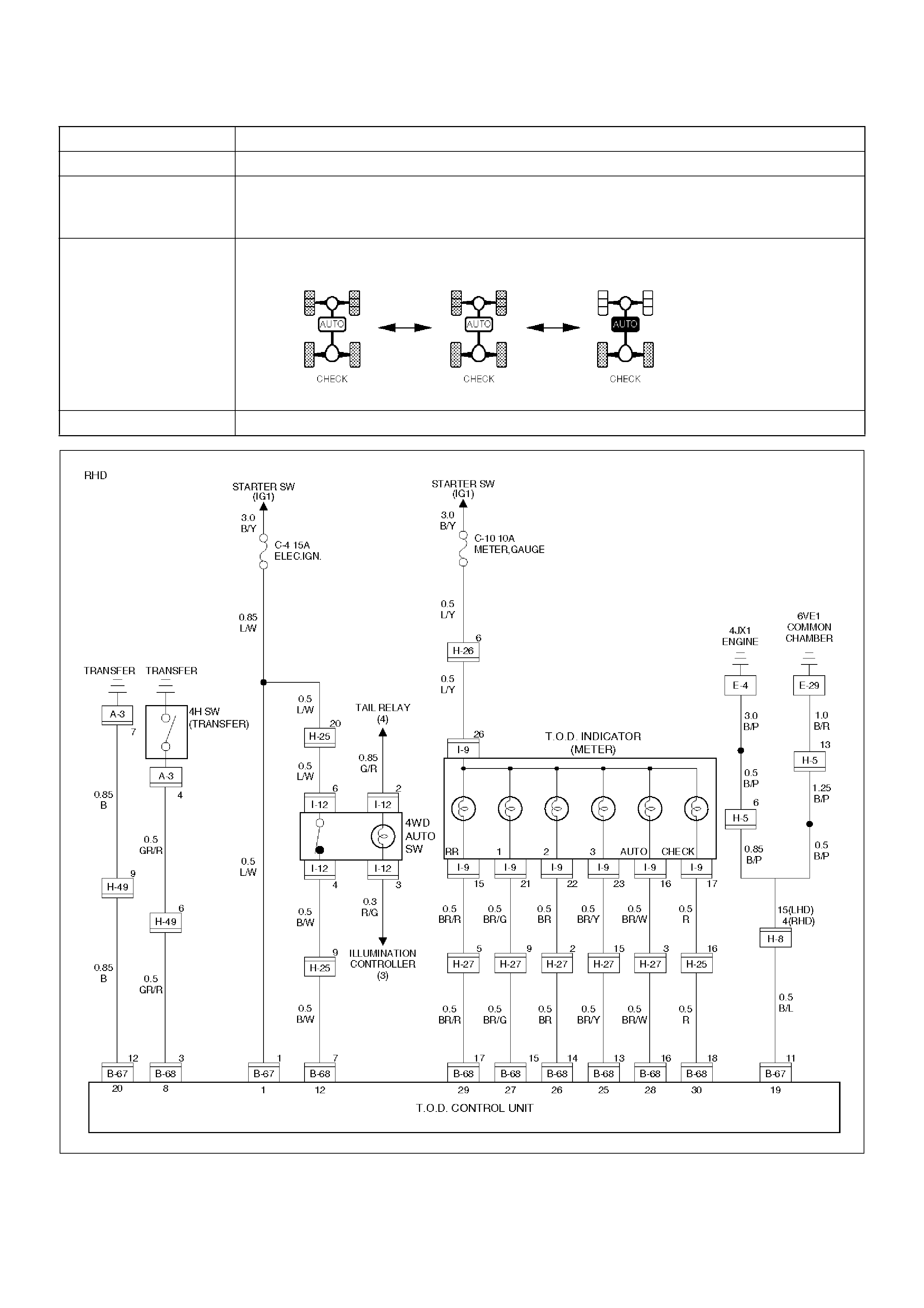
2. While keeping the vehicle standstill, operate the
4WD switch and shift the transfer lever to change
the modes: 2H mode®TOD mode®4L mode®TOD
mode®2H mode. Check that the TOD indicator
lamps correctly display the status whenever the
mode is changed. If the transition status is
displayed during the shift operation, run the vehicle
a little to complete shifting.
3. Slowly start the vehicle in the TOD mode, and add
the power to accelerate to at least 40 km/h and
maintain the speed for about two minutes. Apply
the brake to completely stop the vehicle. Repeat
this test pattern at least three times.
4. Turn the steering to the right end (or left end) in the
TOD mode, and slowly start the vehicle and make a
circle five times. Next, conduct the same test in the
2H mode.
5. Slowly start the vehicle in the TOD mode, and
accelerate to at least 40 km/h. Keep the established
speed, carefully change the mode in the sequence
“TOD mode®2H mode ®TOD mode” while
checking that the shift is complete in each mode
change. After the test, apply the brake to
completely stop the vehicle.

6. Slowly start the vehicle in the TOD mode, and
accelerate to at least 40 km/h. Apply the brake
strongly so that the ABS works, and completely stop
the vehicle.
7. Slowly start the vehicle in the 4L mode, and
accelerate to at least 20 km/h. Apply the brake to
completely stop the vehicle.
If the CHECK lamp starts blinking during the test run,
read the trouble codes and give appropriate
maintenance according to the diagnostic procedure. If
the TOD indicator lamps are lit abnormally during the
run, check the lighting condition and give appropriate
maintenance according to the diagnostic procedure.
Even if the phenomena are not observed, try to
reproduce the abnormal state reported by the customer
to the possible extent.
Post-Repair Check
As long as the starter is not turned off, the TOD indicator
lamps continue blinking even after the failed portion
repaired. Therefore, upon completion of repair, be sure
to turn off the starter switch once and then turn on it to
conduct the test run sequence specified in steps 1
through 7 above and check that the TOD indicator
lamps no longer show any faulty status.
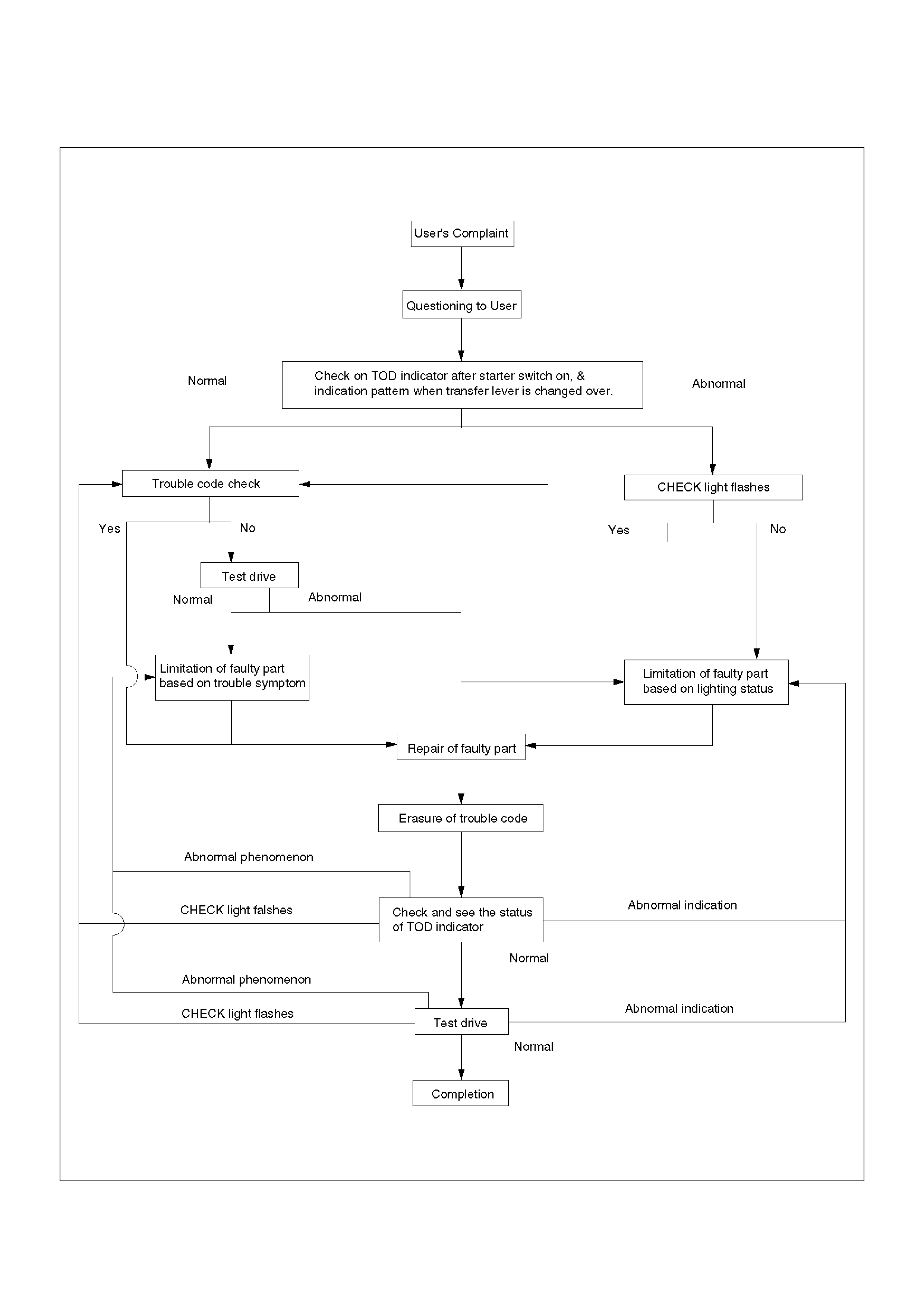
Basic Diagnostic Flow Chart
C04RY00015
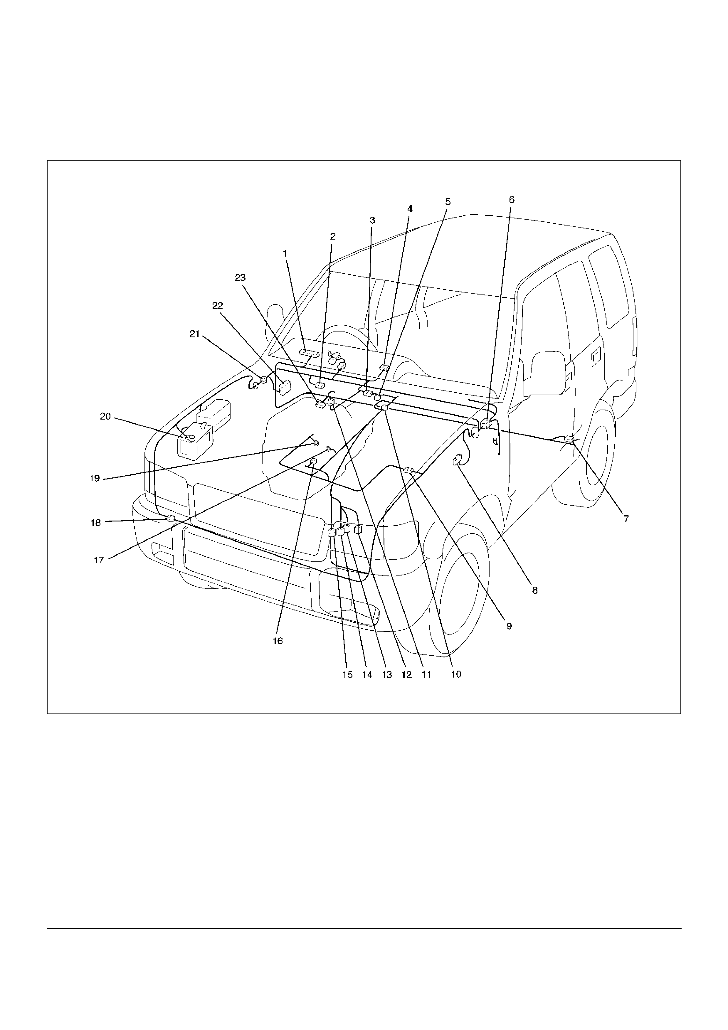
Parts Location
Parts Location - 6VE1
D08RW621
EndOFCallout
Legend
(1) I–9
(2) B–13 or B–14
(3) H–12
(4) I–12
(5) A–3
(6) H–7, H–8
(7) H–32
(8) C–16
(9) H–5, H–6
(10) C–63
(11) H–49
(12) M–22
(13) M–23
(14) M–24
(15) H–10
(16) E–5
(17) E–29
(18) H–42
(19) E–30
(20) Battery
(21) H–13, H–15, H–25, H–26, H–27
(22) Fuse Box
(23) B–67, B–68
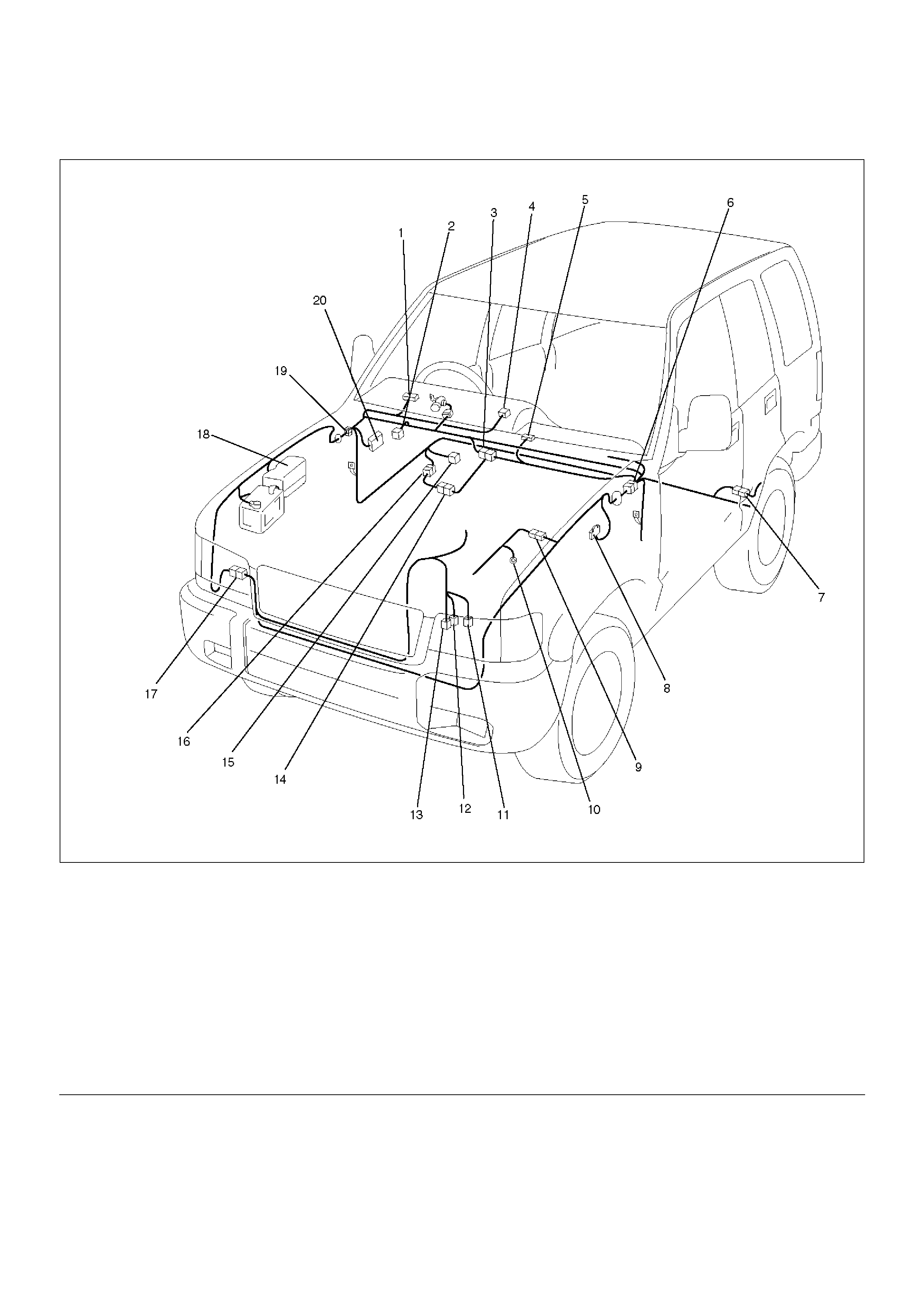
Parts Location - 4JX1
D08RW753
EndOFCallout
Legend
(1) I–9
(2) B–13 or B–14
(3) H–12
(4) I–12
(5) C–63
(6) H–7, H–8
(7) H–32
(8) C–16
(9) H–5, H–6
(10) E–4
(11) P–17
(12) P–18
(13) P–19
(14) A–3
(15) B–67, B–68
(16) H–49
(17) H–60
(18) Relay and Fuse Box
(19) H–15, H–25, H–26, H–27
(20) Fuse Box
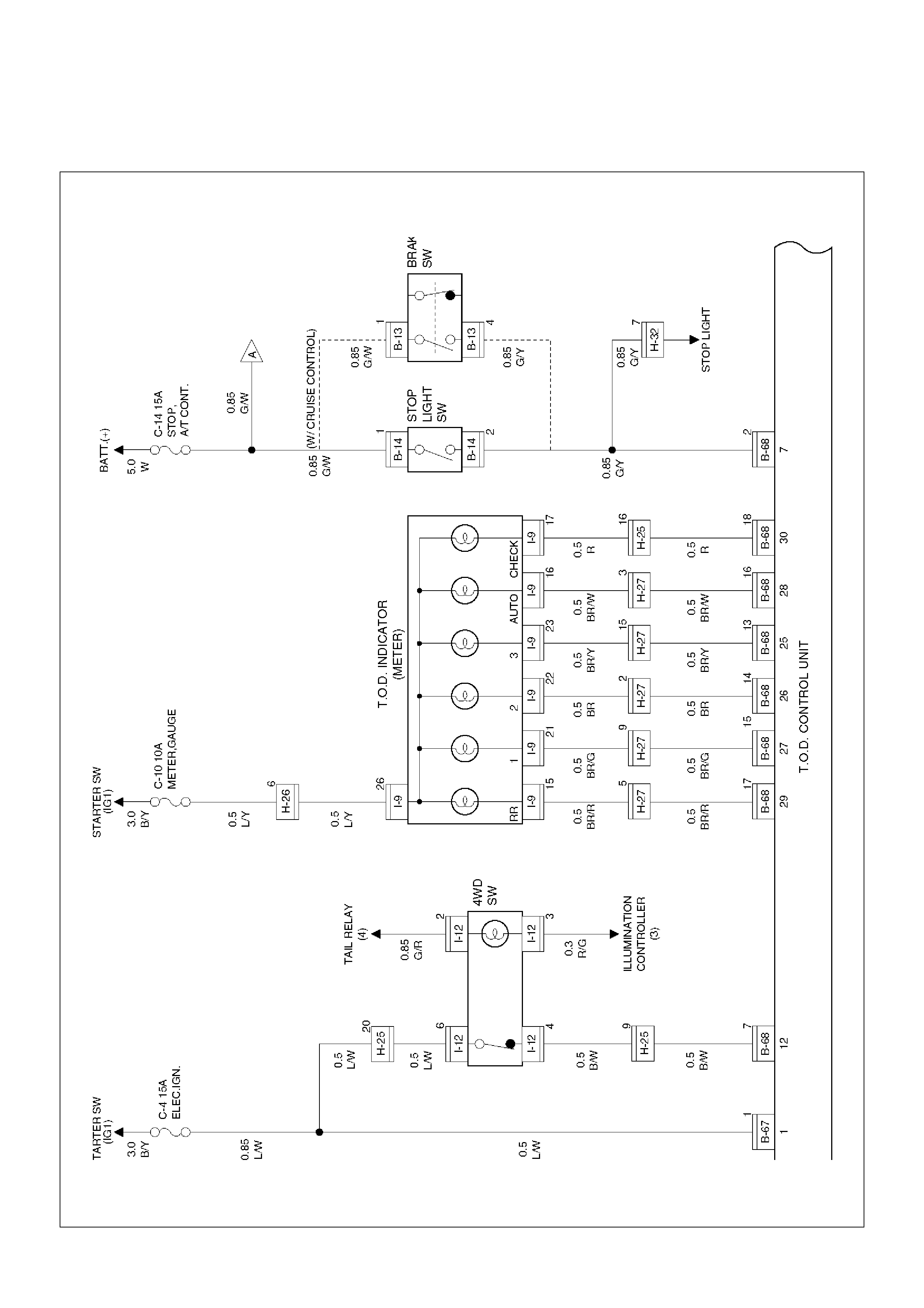
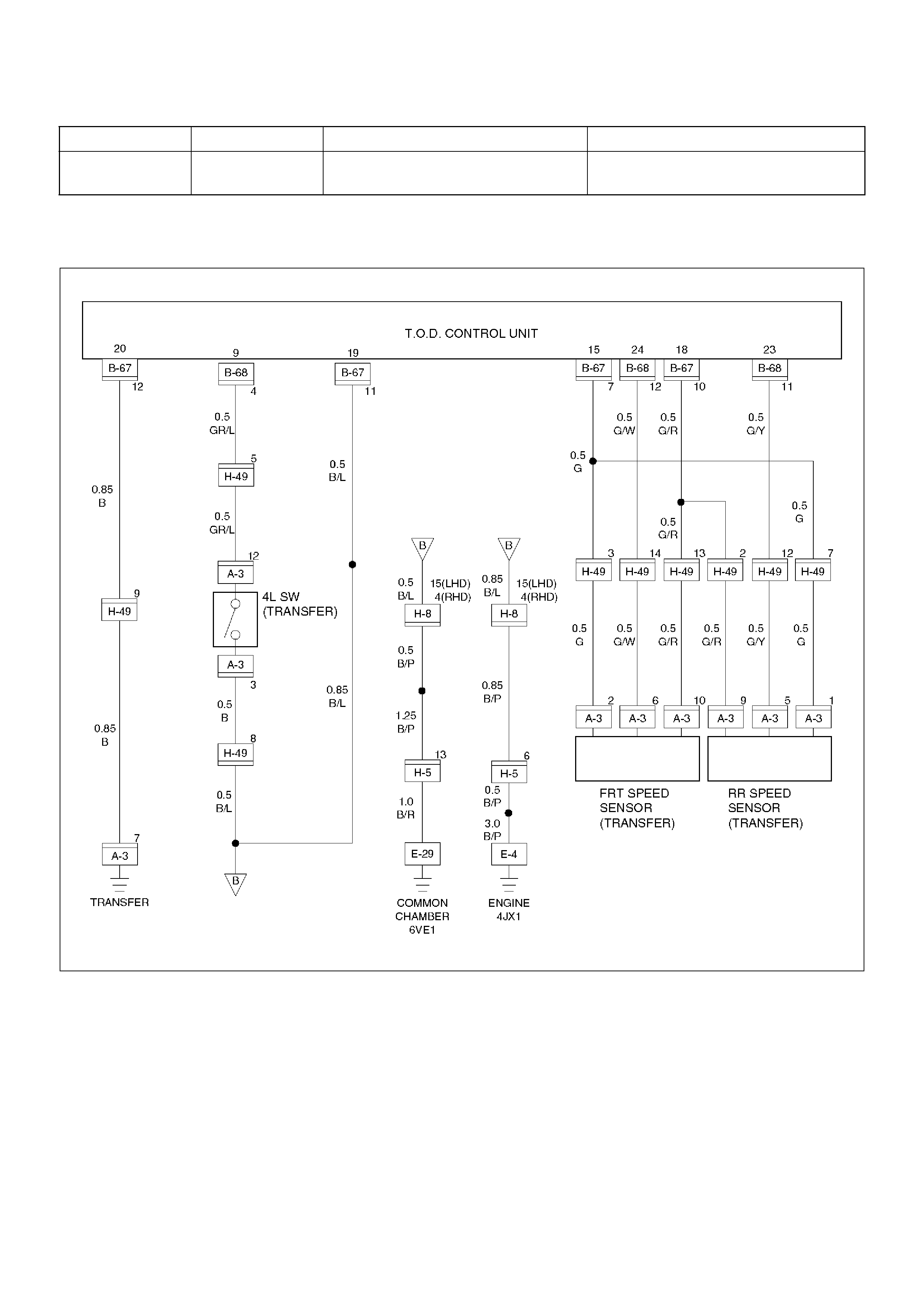
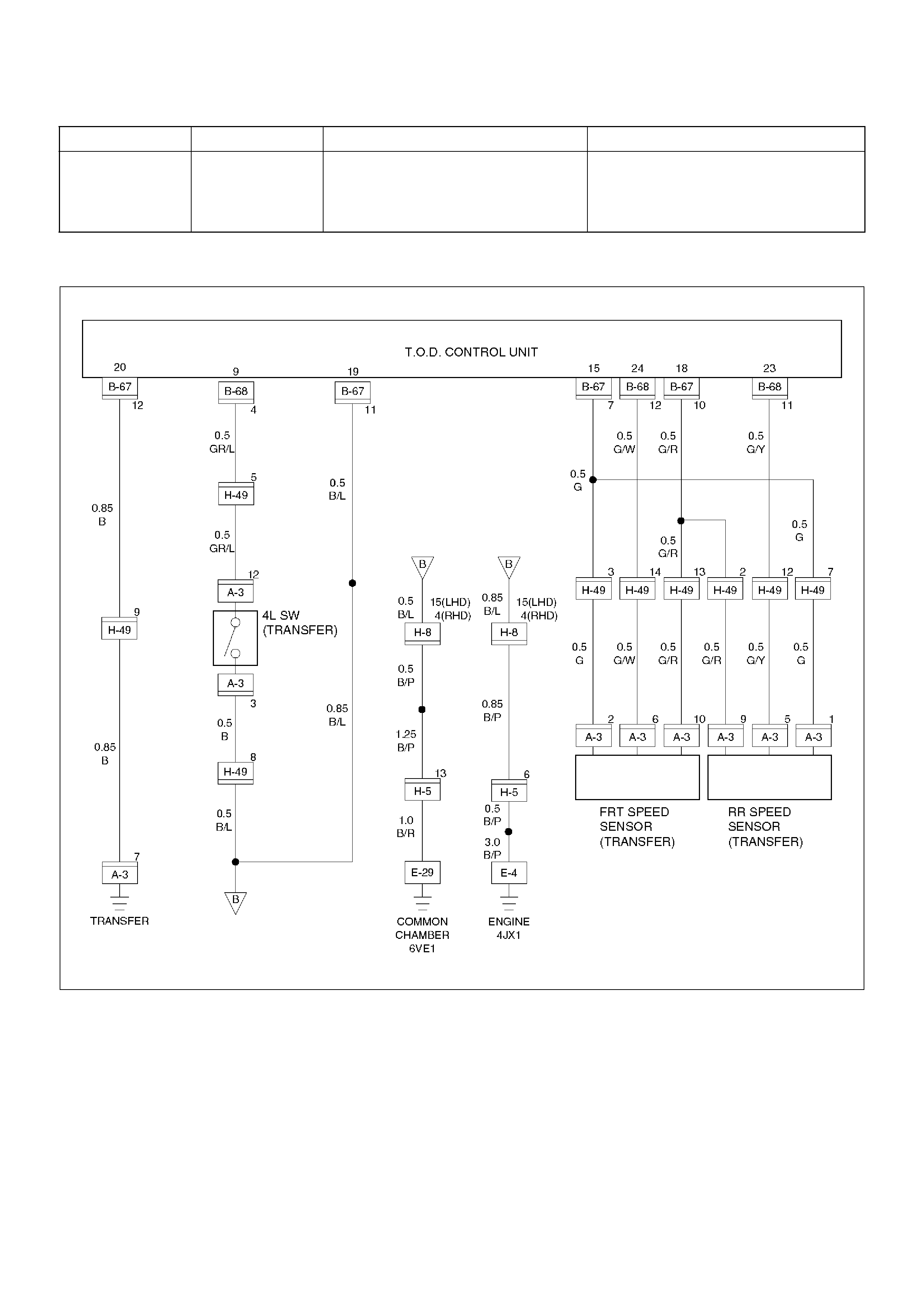
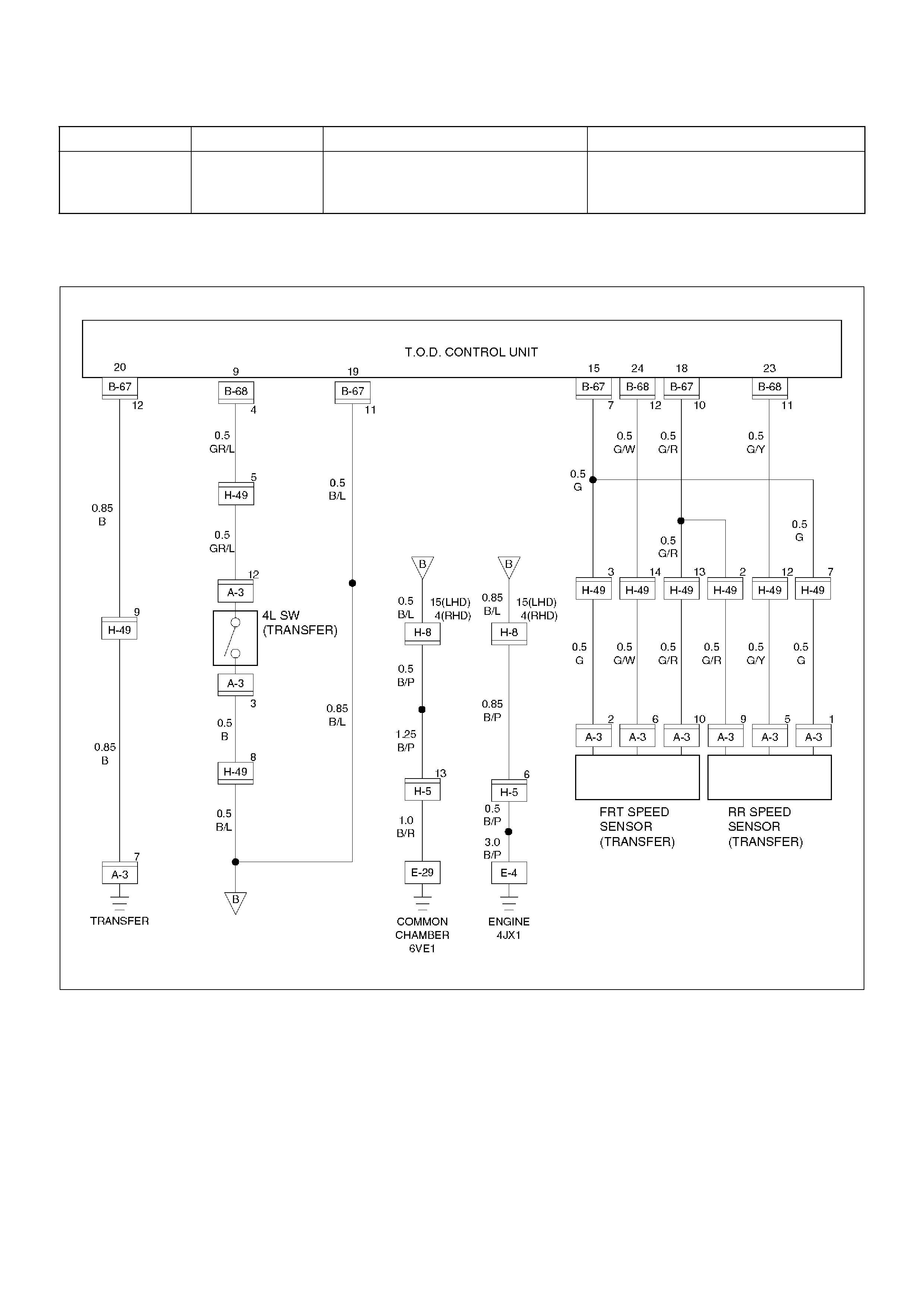
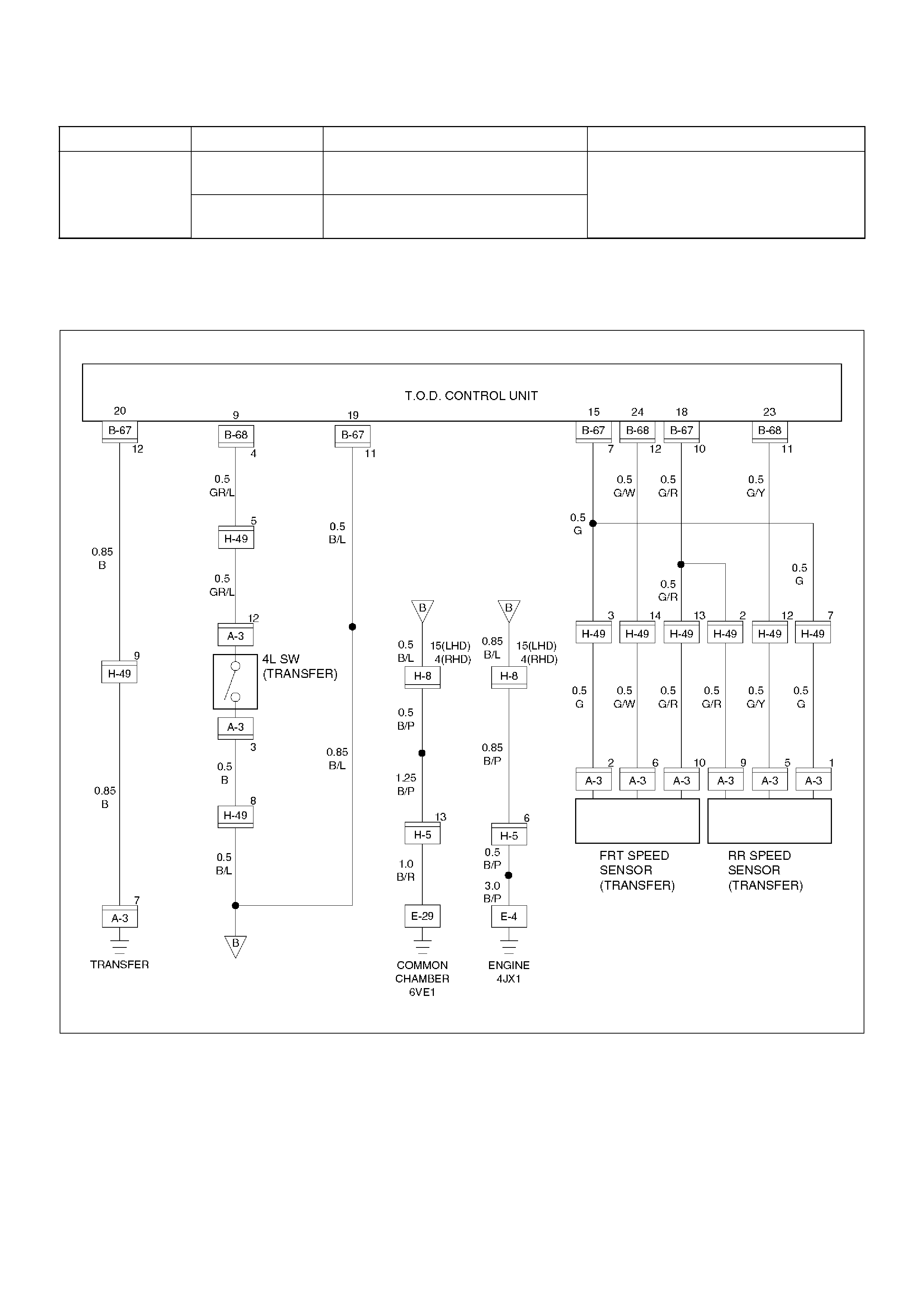
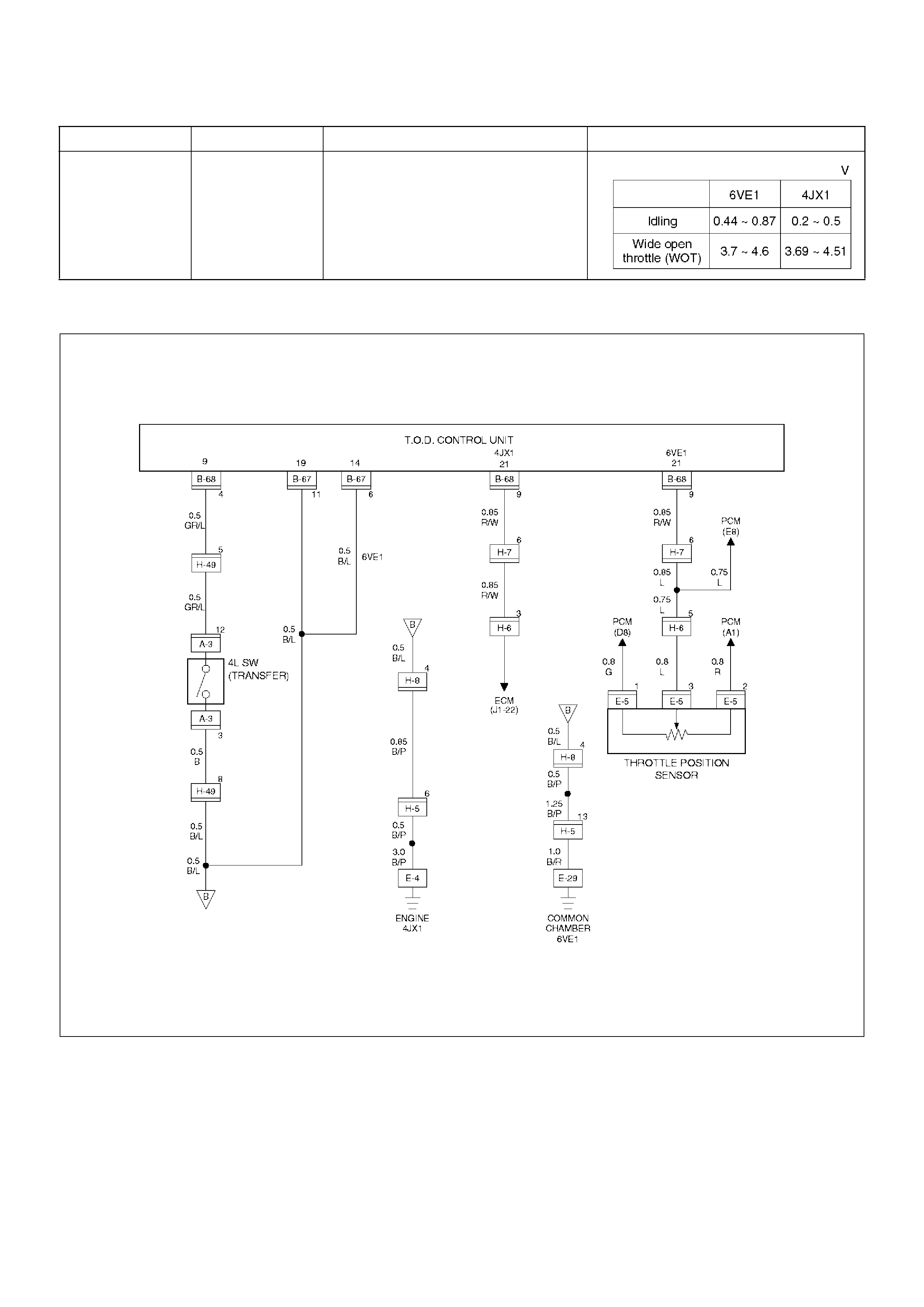
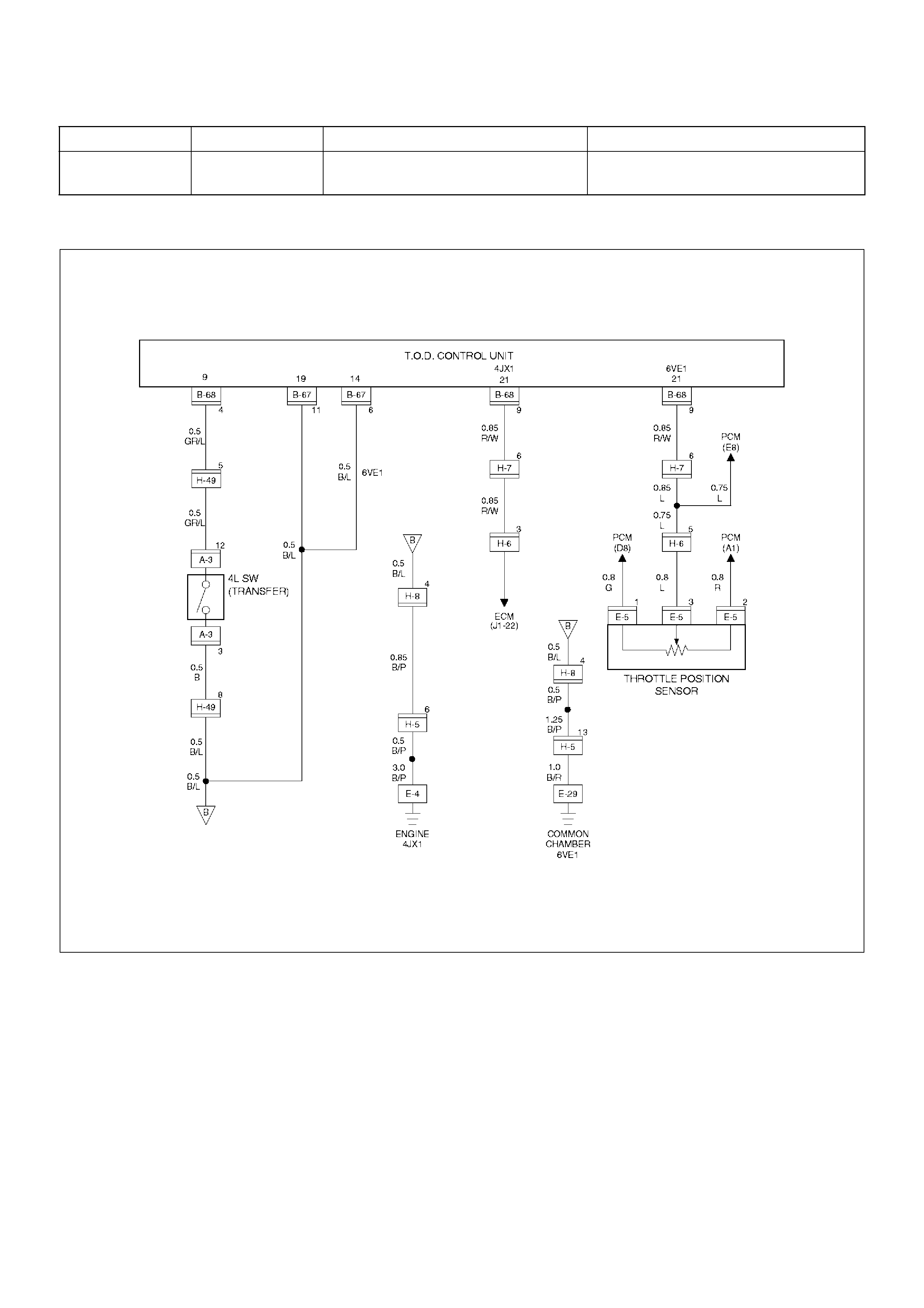
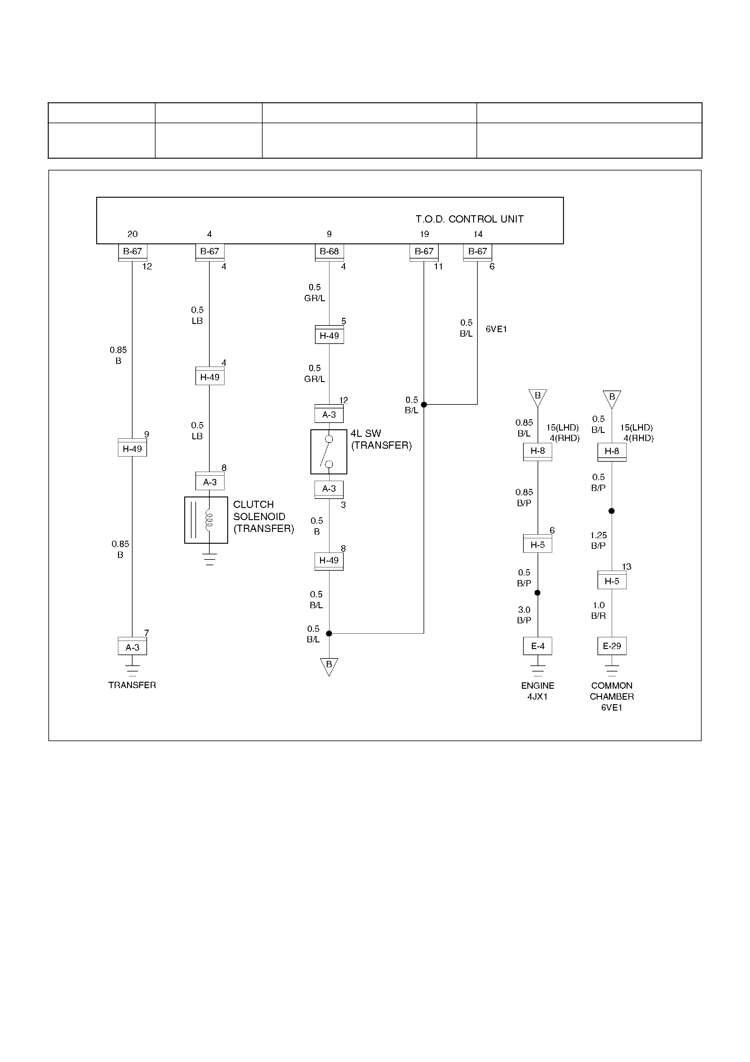
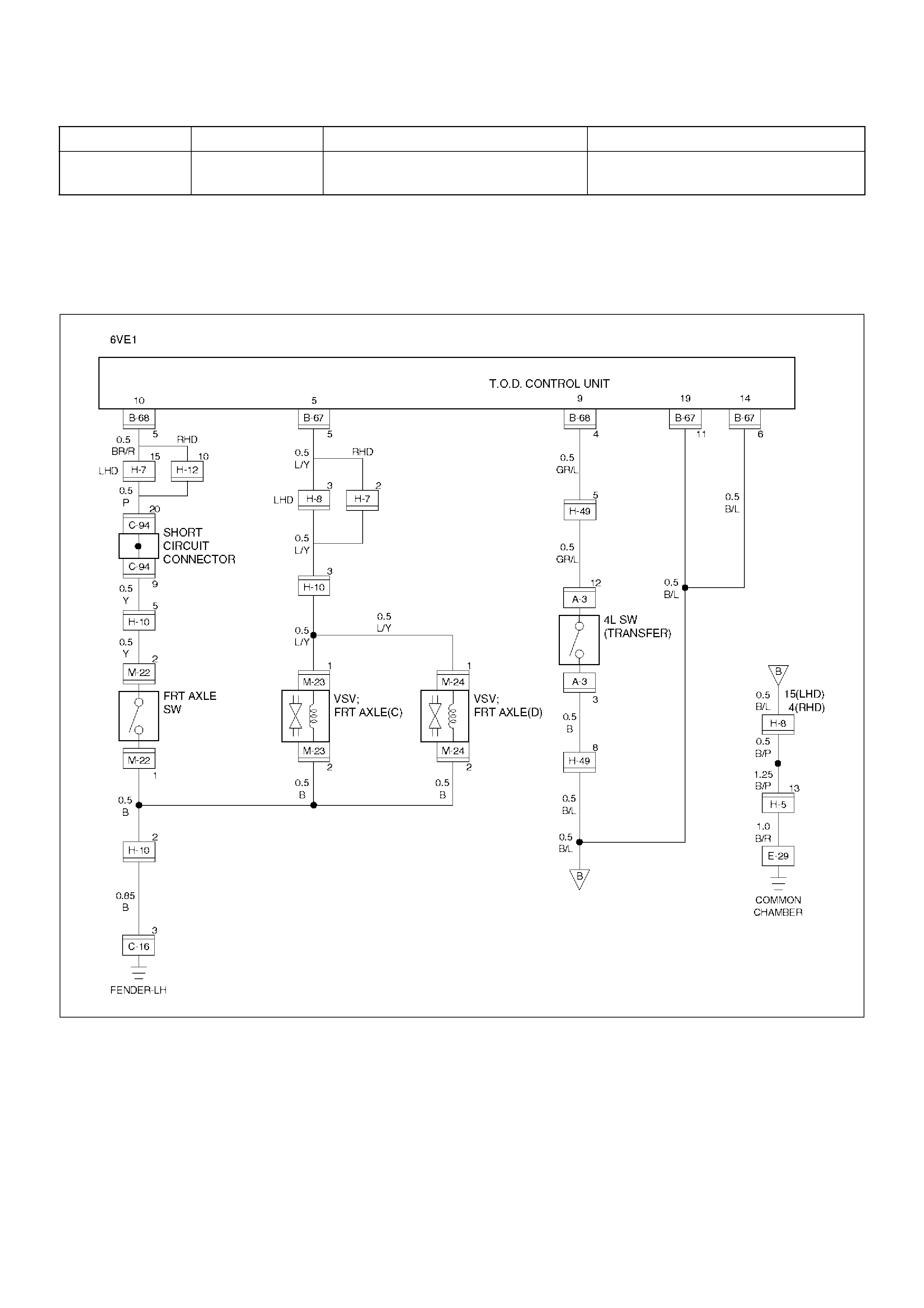
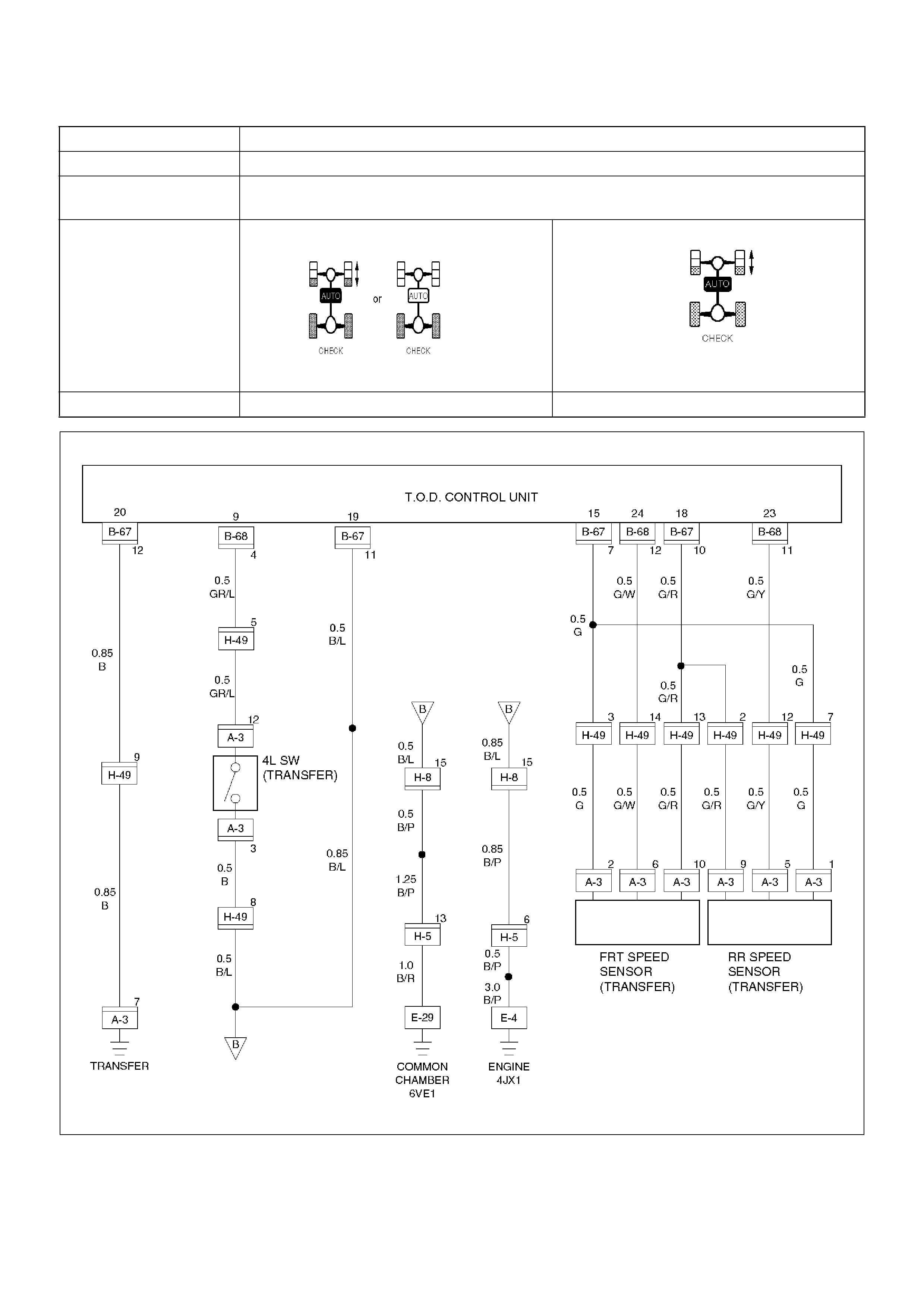
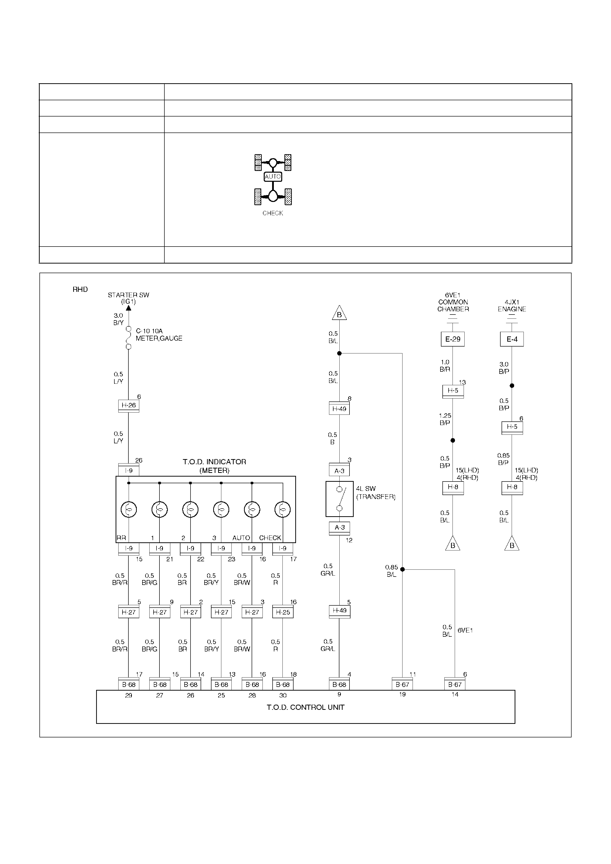
Circuit Diagram
Circuit Diagram - 6VE1 - 1
D04RY00041
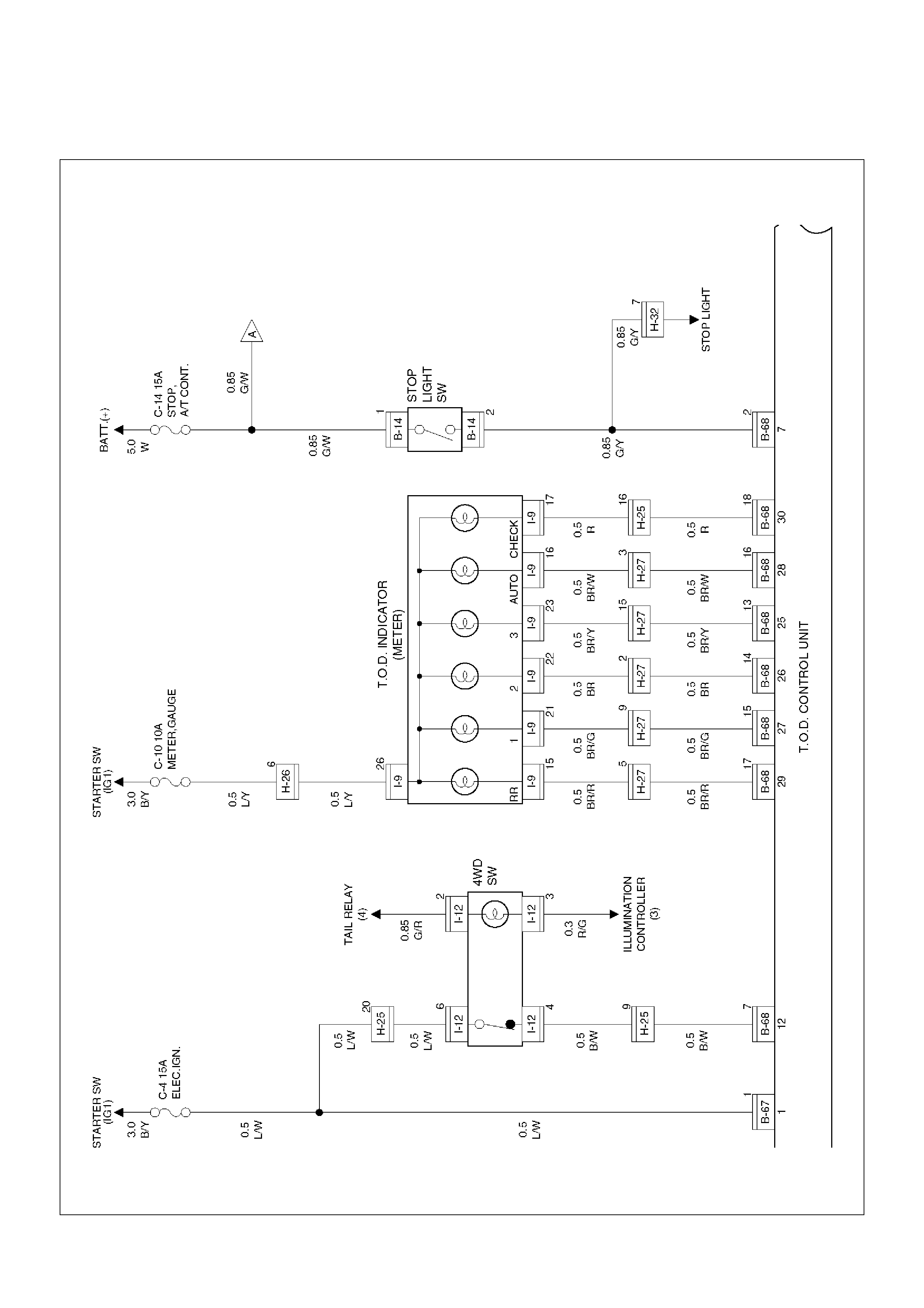
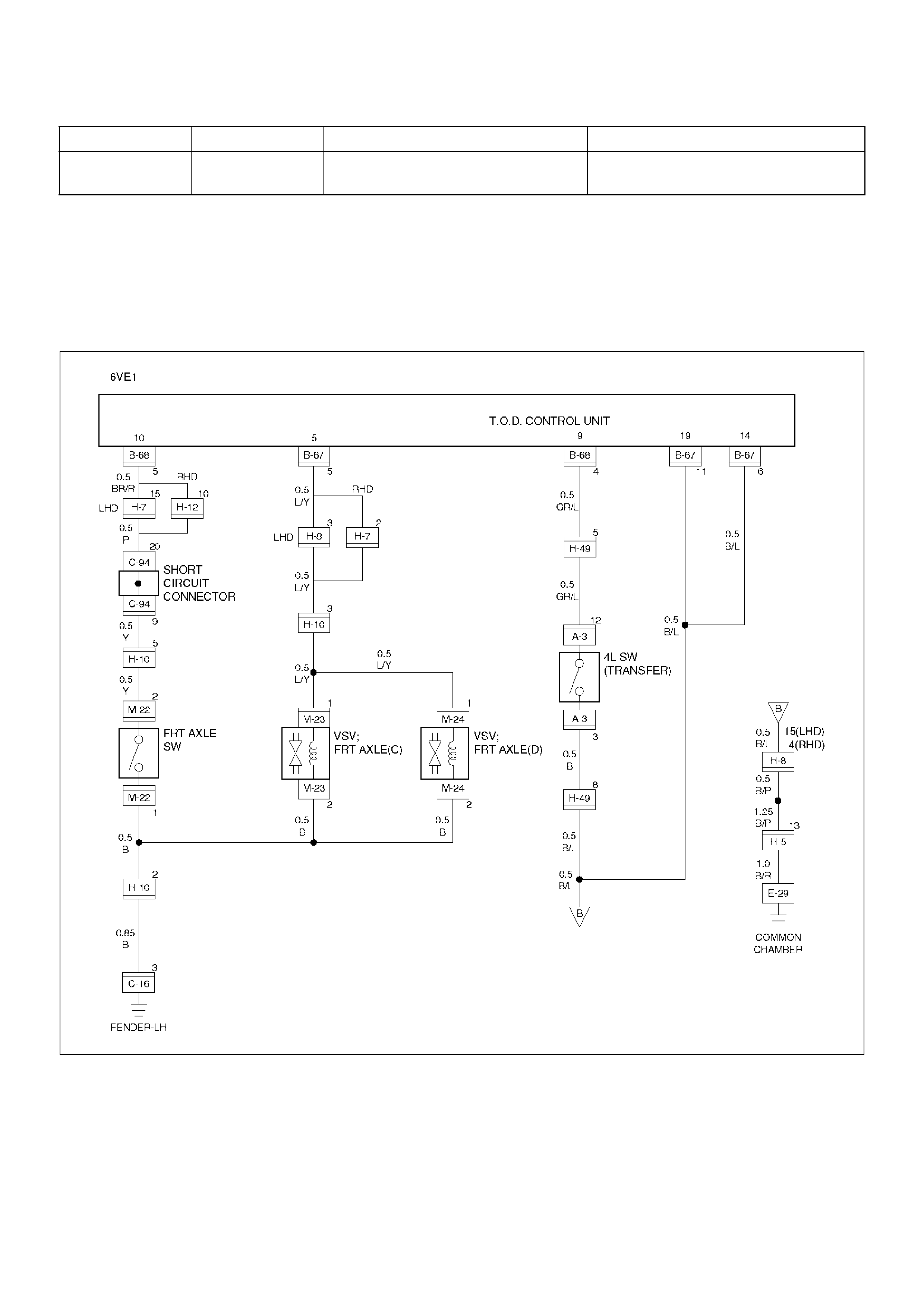
Circuit Diagram - 6VE1 - 2
D04RY00042

Circuit Diagram - 6VE1 - 3
D04RY00043
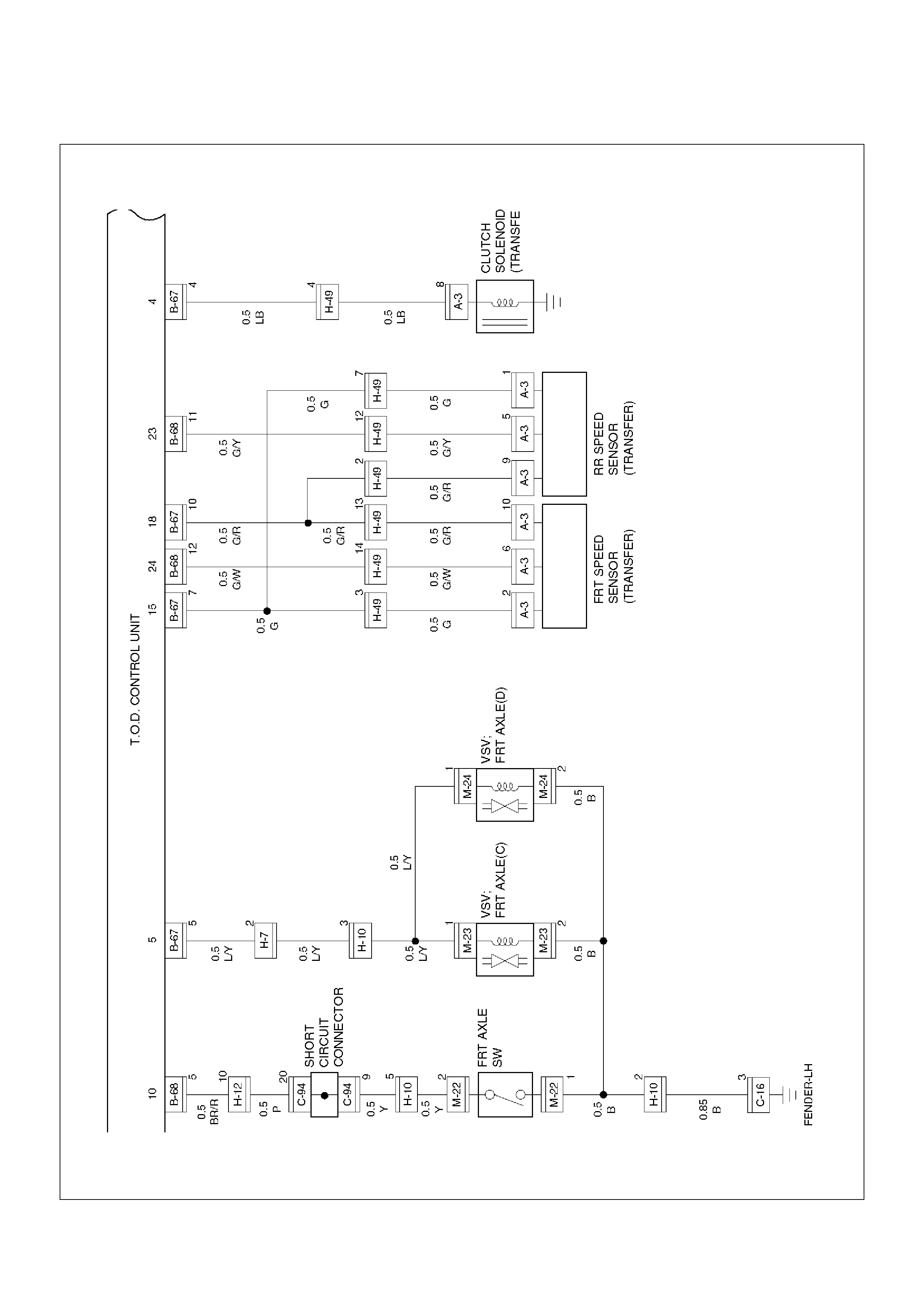
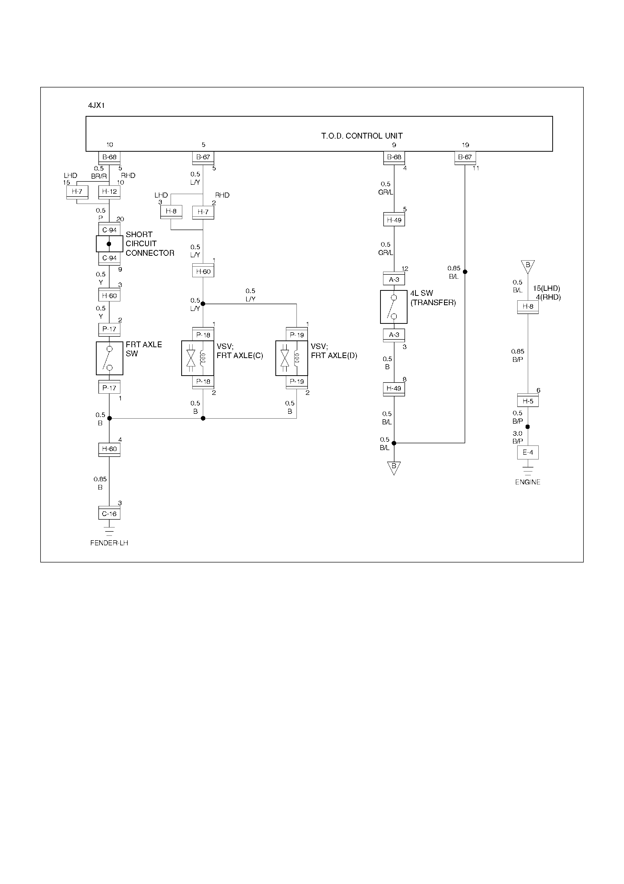
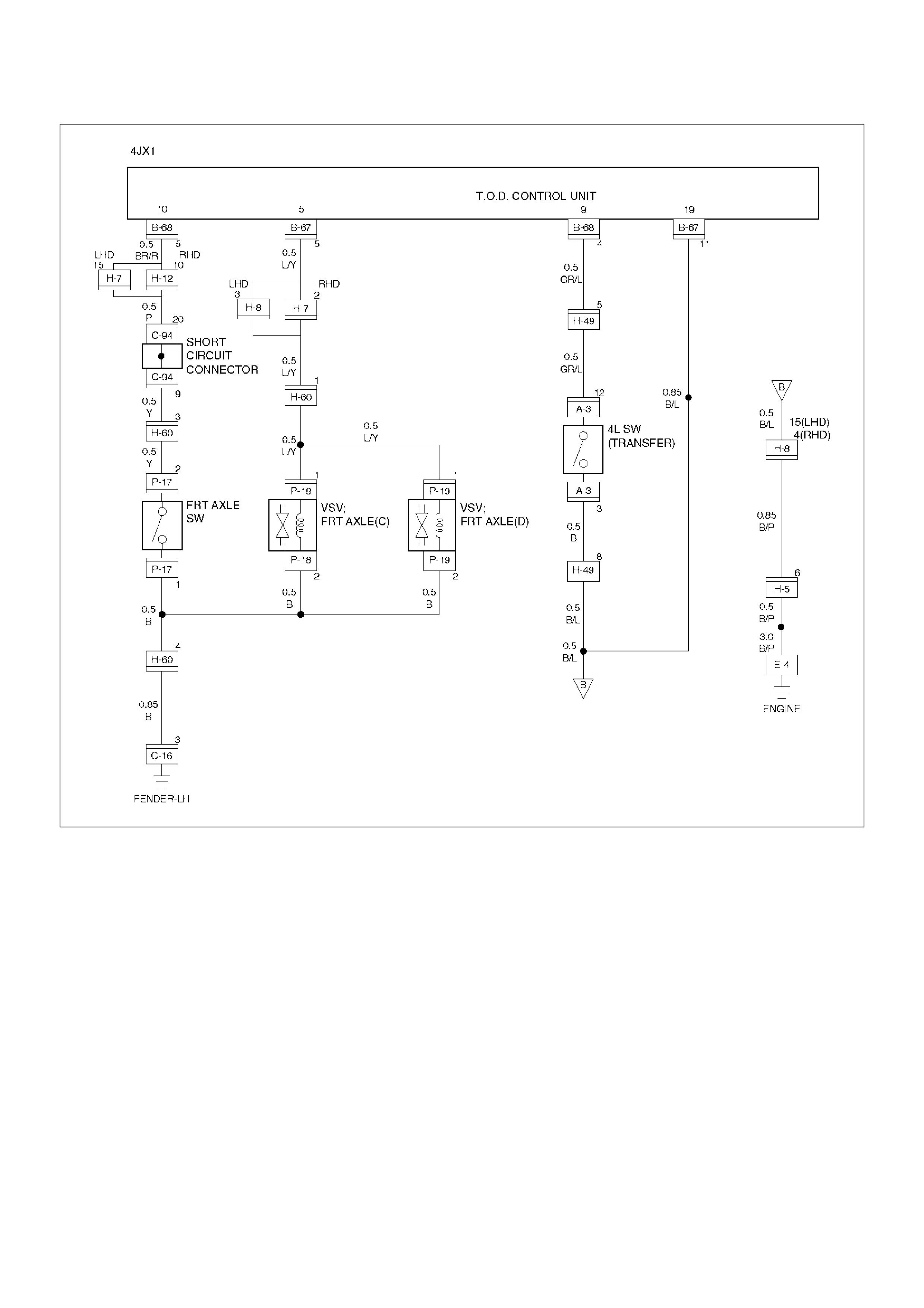
Circuit Diagram - 4JX1 - 1
D04RY00044
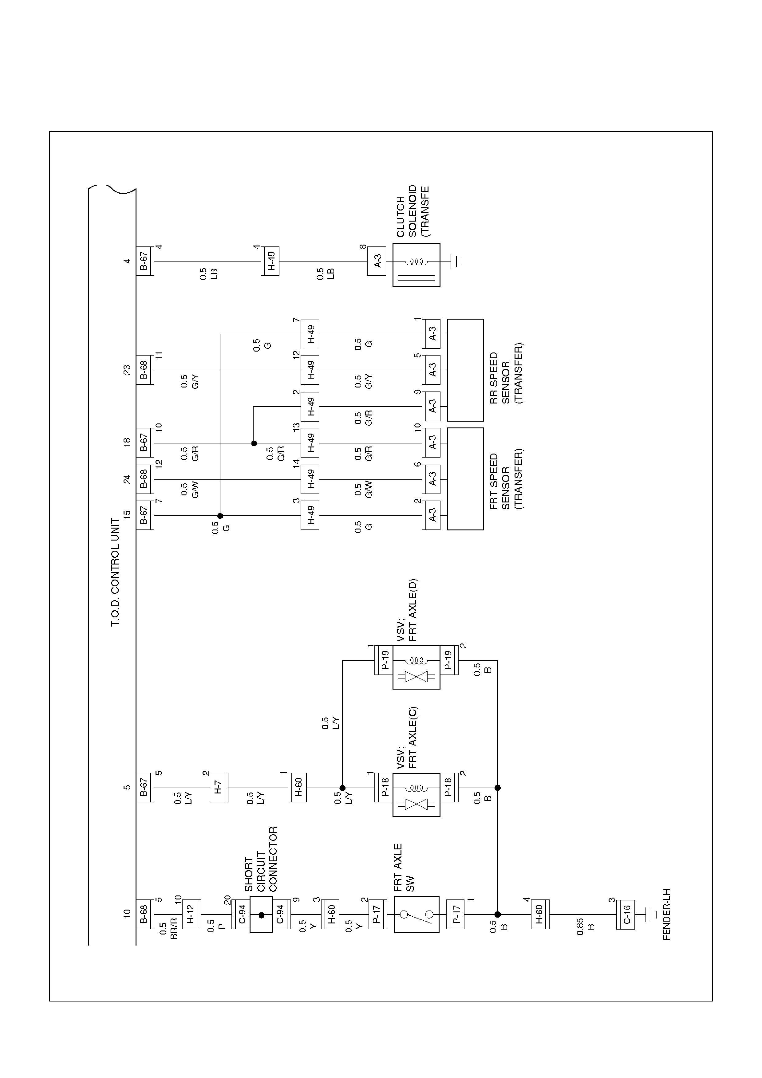
Circuit Diagram - 4JX1 - 2
D04RY00045
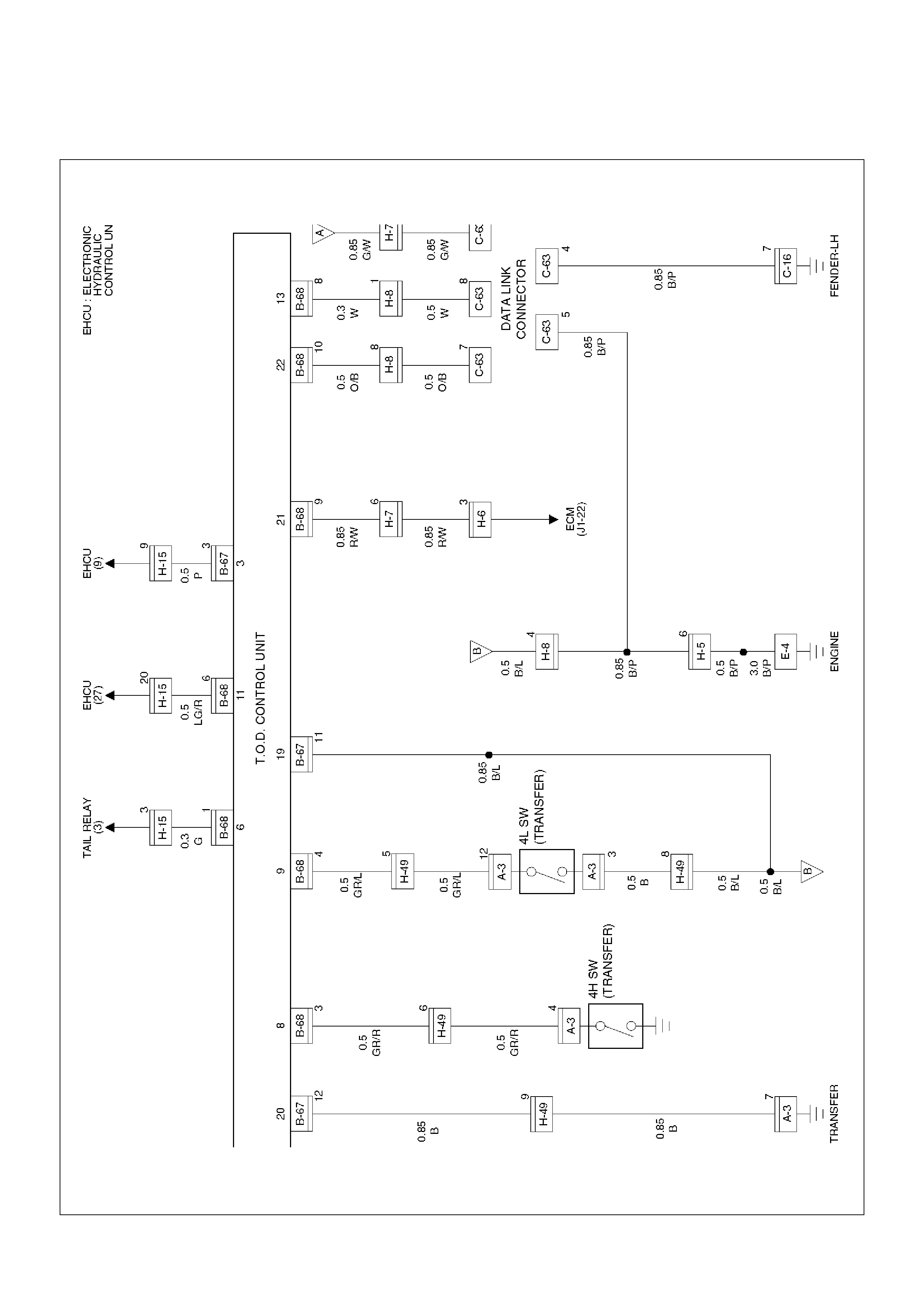
Circuit Diagram - 4JX1 - 3
D04RY00046
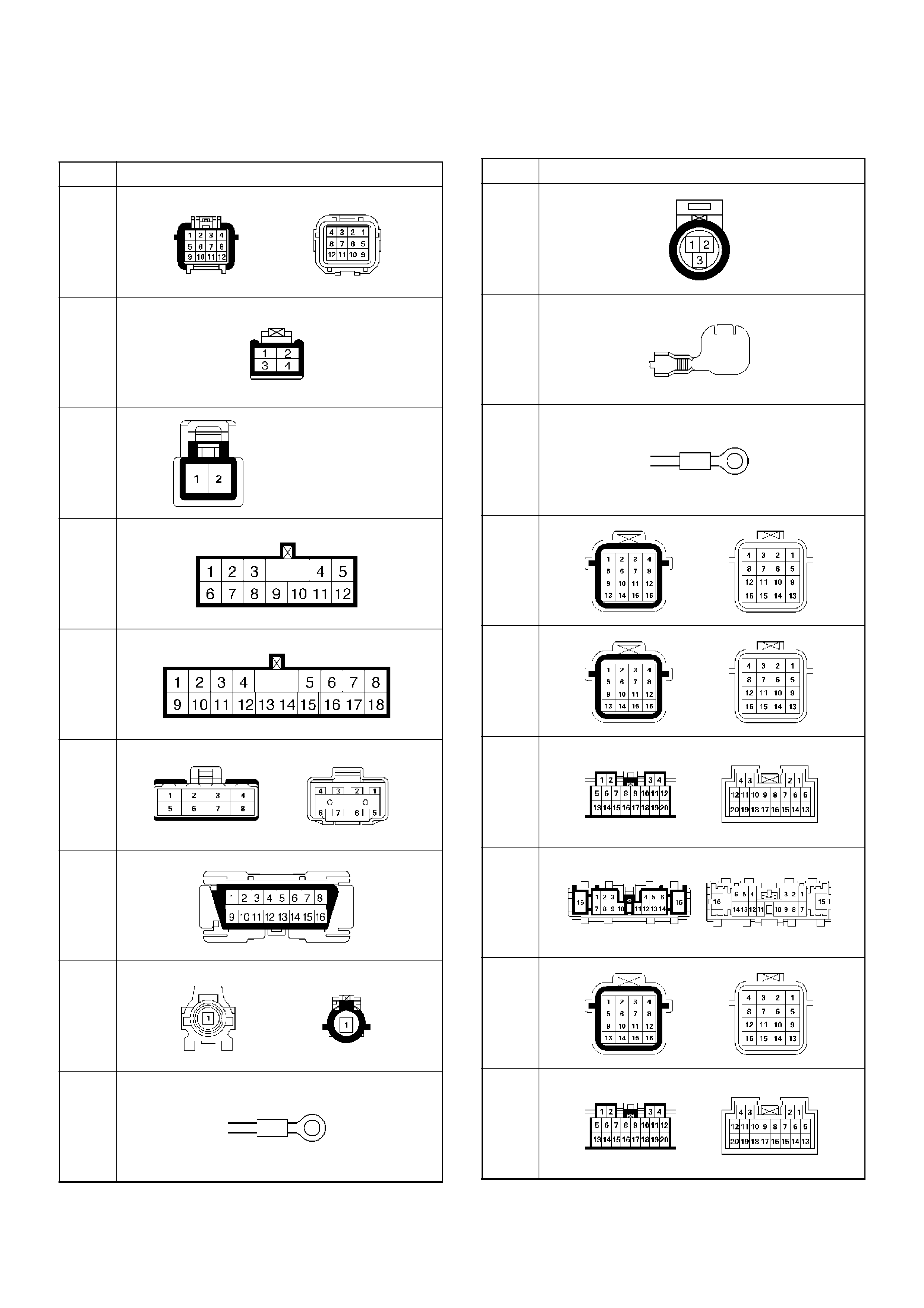
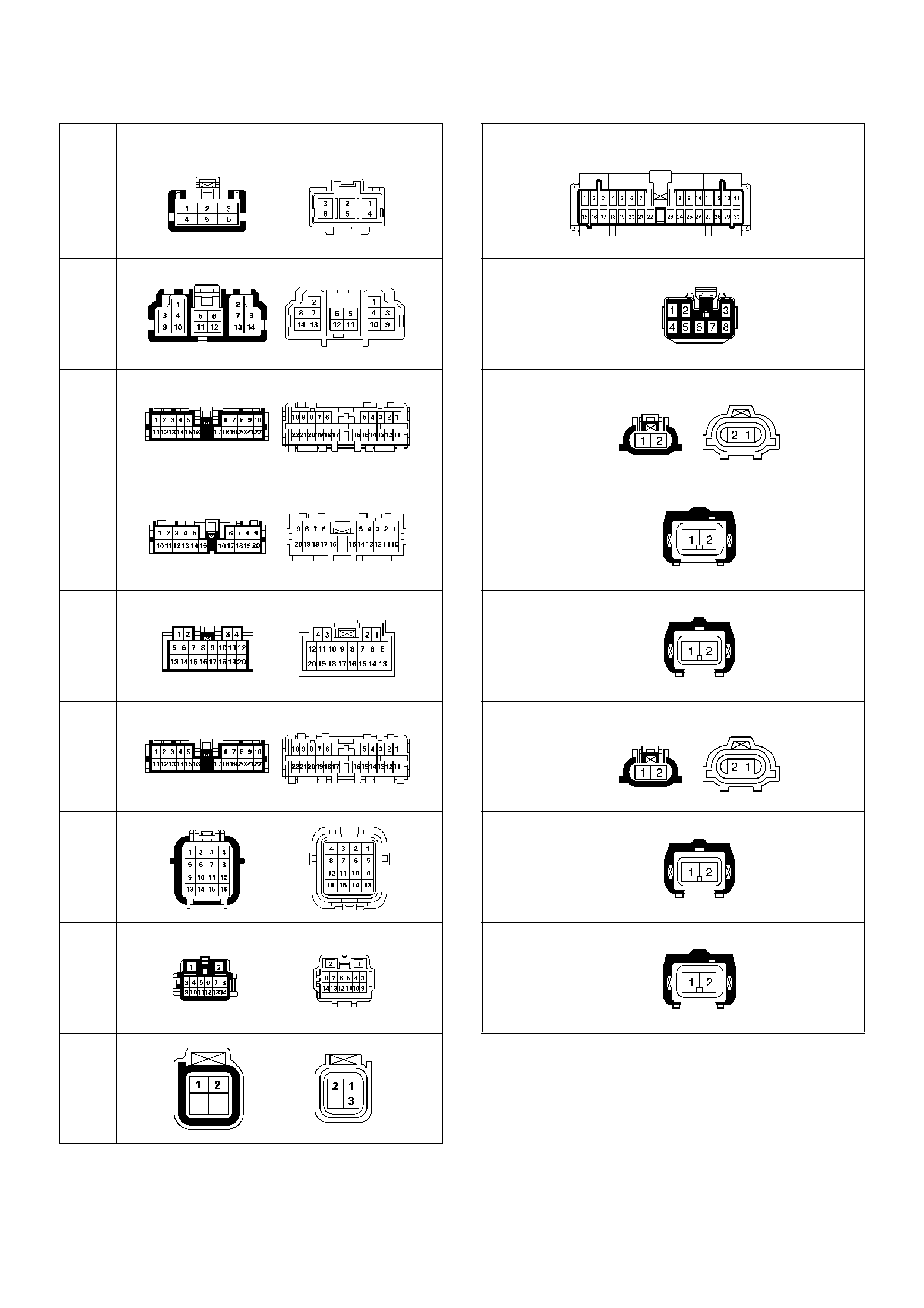
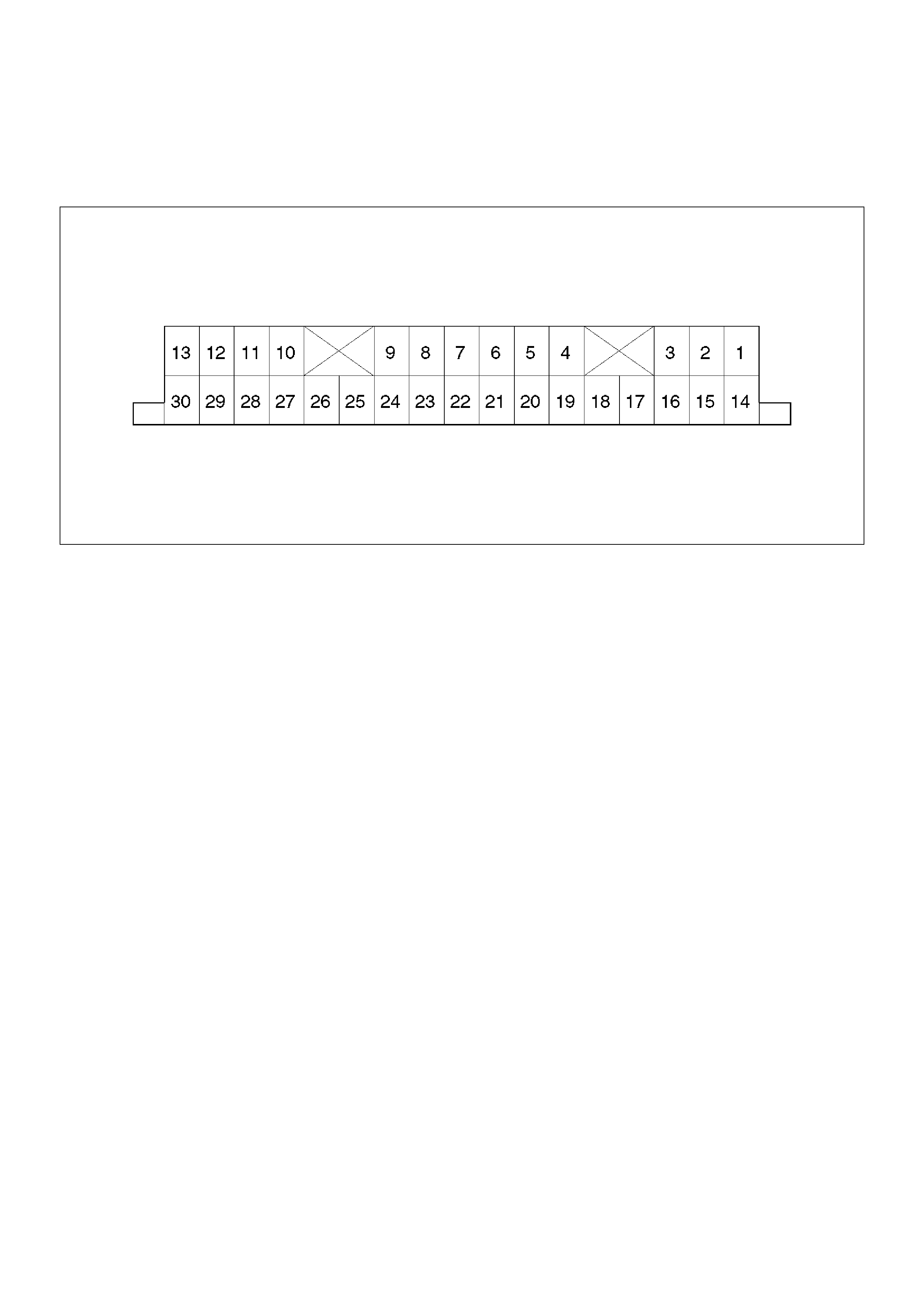
Connector List
No. Connector face
A-3
B-13
B-14
B-67
B-68
C-16
C-63
E-4
(6VE1
)
E-4
(4JX1
)
E-5
(6VE1
)
E-29
(6VE1
)
E-30
(6VE1
)
H-5
(6VE1
)
(4JX1
–A/T)
H-6
H-7
H-8
H-10
H-12
No. Connector face
H-13
H-15
H-25
H-26
H-27
H-32
H-42
H-49
H-60
No. Connector face
I-9
I-12
M-22
M-23
M-24
P-17
(4JX1
)
P-18
(4JX1
)
P-19
(4JX1
)
No. Connector face
Checking Failed Pin
Connector Pin Assignment
• ECU pin assignment
D04RW032

No. NAME CONTENTS
1 VIG Power supply (IG)
2 N.C Not used
3 4WD OUT 4WD signal output
4 SOL (+) Electromagnetic solenoid
5 ADC (+) Axle disconnect output
6 LIGHTING SW Lighting SW input
7 BRAKE Brake SW input
8 4H SW 4H SW input
9 4L SW 4L SW input
10 AXEL SW AXEL SW input
11 ABS IN Operation signal input
12 TOD SW TOD SW input
13 DIAG Self-diagnosis input
14 D-G MAP D-G MAP recognition input (Only V6 engine)
15 Ref. Vehicle speed sensor supply
16 N.C Not used
17 N.C Not used
18 COM (–) Vehicle speed sensor GND
19 S-GND Sensor GND
20 P-GND Power GND
21 TPS Throttle position sensor
22 TECH 2 TECH 2 output
23 Rer. Sig Rear vehicle speed sensor input
24 Frt. Sig Front vehicle speed sensor input
25 IND.a 4WD display signal a
26 IND.b 4WD display signal b
27 IND.c 4WD display signal c
28 IND.AUTO AUTO display output
29 IND Rr Rear display output
30 CHECK TOD warning lamp
Reference
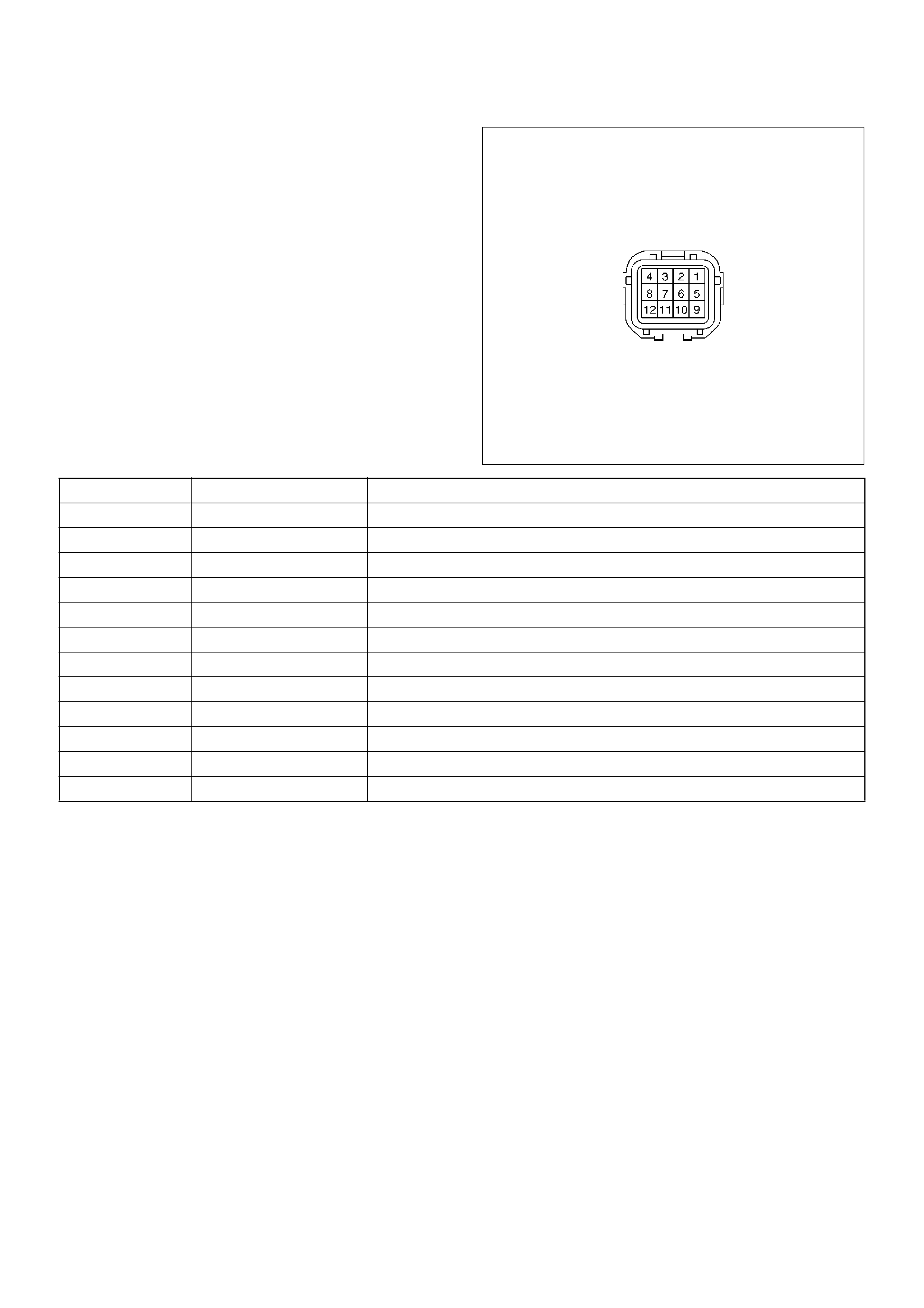
• Transfer connector pin assignment (connector on the
transfer case)
for inspection of transfer pins.
810RW310
No. NAME CONTENTS
1 Ref. (Rer. ) Rear speed sensor reference output
2 Ref. (Frt. ) Front speed sensor reference output
3SW GNDSW GND
4 4H SW (+) 4H SW plus terminal
5 Rer. (+) Rear speed sensor plus
6 Frt. (+) Front speed sensor plus
7 POWER GND Power GND
8 SOL (+) Electromagnetic solenoid
9 COM (–) (Rer. ) Rear speed sensor GND
10 COM (–) (Frt. ) Front speed sensor GND
11 NC Not used
12 4L SW (+) 4L SW plus terminal

Checking Failed TOD Control Unit
Pin
NOTE:
1. Unplug the ECU connector and the pins, unless
otherwise specified.
2. Before removing the ECU, turn off the ignition
switch.
3. If the standard values are not observed, check the
pins with other testers.
Pin
No.
Circuit to
be tested
Ignition
Switch
Engine
State
DMM
Scale/
Range
Measure
between Pin
Number
Standard Valve Note
14 D-G MAP OFF STOP W14, 19 Continuity : OK
(Petrol)
No continuity : OK
(Diesel)
20 P-GND OFF STOP W20, 19 Continuity : OK
19 GND OFF STOP W19, GND Continuity : OK
84H SW OFF STOP W8, 19 No continuity
(high, 4L) and
continuity (N) :
OK
9 4L SW OFF STOP W9, 19 No continuity
(high) and
continuity (4L, N)
: OK
10 AXLE SW ON RUN W10, 19 Continuity : OK Remove ECU and start the
engine. Move the vehicle forth
and back to connect axle surely.
13 DIAG OFF STOP W13 (TOD), 8
(DLC
Connector)
Continuity : OK DLC connector terminal 8
25 IND.a ON STOP DCV 25 (+), 19 (–) 8.0 ~14.5 V
When the
indicator lamp is
turned off.
26 IND.b ON STOP DCV 26 (+), 19 (–) 8.0 ~14.5 V
When the
indicator lamp is
turned off.
27 IND.c ON STOP DCV 27 (+), 19 (–) 8.0 ~14.5 V
When the
indicator lamp is
turned off.
30 CHECK
LAMP
ON STOP DCV 30 (+), 19 (–) 8.0 ~14.5 V
When the
indicator lamp is
turned off.
11 ABS IN ON STOP DCV 11 (+), 19 (–) 11.5 ~14.5 V
15 Ref. ON STOP DCV 15 (+), 19 (–) 5 ~9 V Connect ECU
24 Ft.(+) ON STOP DCV 24 (+), 19 (–) 0.7 ~6 V Connect ECU (off one tooth of
speed sensor ring) and move
the vehicle making sure of
voltage change.
23 Rr.(+) ON STOP DCV 23 (+), 19 (–) 0.7 ~6 V Connect ECU (off one tooth of
speed sensor ring) and move
the vehicle making sure of
voltage change.

18 COM(-) ON STOP DCV 18 (+), 19 (–) 0V Connect ECU
1 Vig ON STOP DCV 1 (+), 19 (–) 8 ~14.5 V
7 BRAKE OFF STOP DCV 7 (+), 19 (–) 8 ~14.5 V Press brake pedal
21 TPS ON STOP DCV 21 (+), 19 (–) 0.2 ~4.6 V Step on the accelerator pedal
and make sure that voltage
changes.
3 4WD OUT OFF STOP W3, 19 7 ~12 kWDisconnect battery GND
terminal
5 ADC(+) OFF STOP W5, 19 10 ~30 WDisconnect battery GND
terminal
4SOL(+) OFF STOP W4, 19 1.0 ~5.0 WDisconnect battery GND
terminal
12 4WD SW ON STOP DCV 12 (+), 19 (–) SW OFF : 0 V
SW ON : 8.0
~14.5 V
SW OFF : Contact point open
SW ON : Contact point close
6 LIGHTING ON STOP DCV 6 (+), 19 (–) SW OFF : 8.0
~14.5 V
SW ON : 0 V
28 AUTO
INDI
ON STOP DCV 28 (+), 19 (–) TOD : 0 V
2H & 4L : 8.0
~14.5 V
Connect ECU
29 RR INDI ON STOP DCV 29 (+), 19 (–) 0 V Connect ECU. When the
indicator lamp is turned on.
Pin
No.
Circuit to
be tested
Ignition
Switch
Engine
State
DMM
Scale/
Range
Measure
between Pin
Number
Standard Valve Note
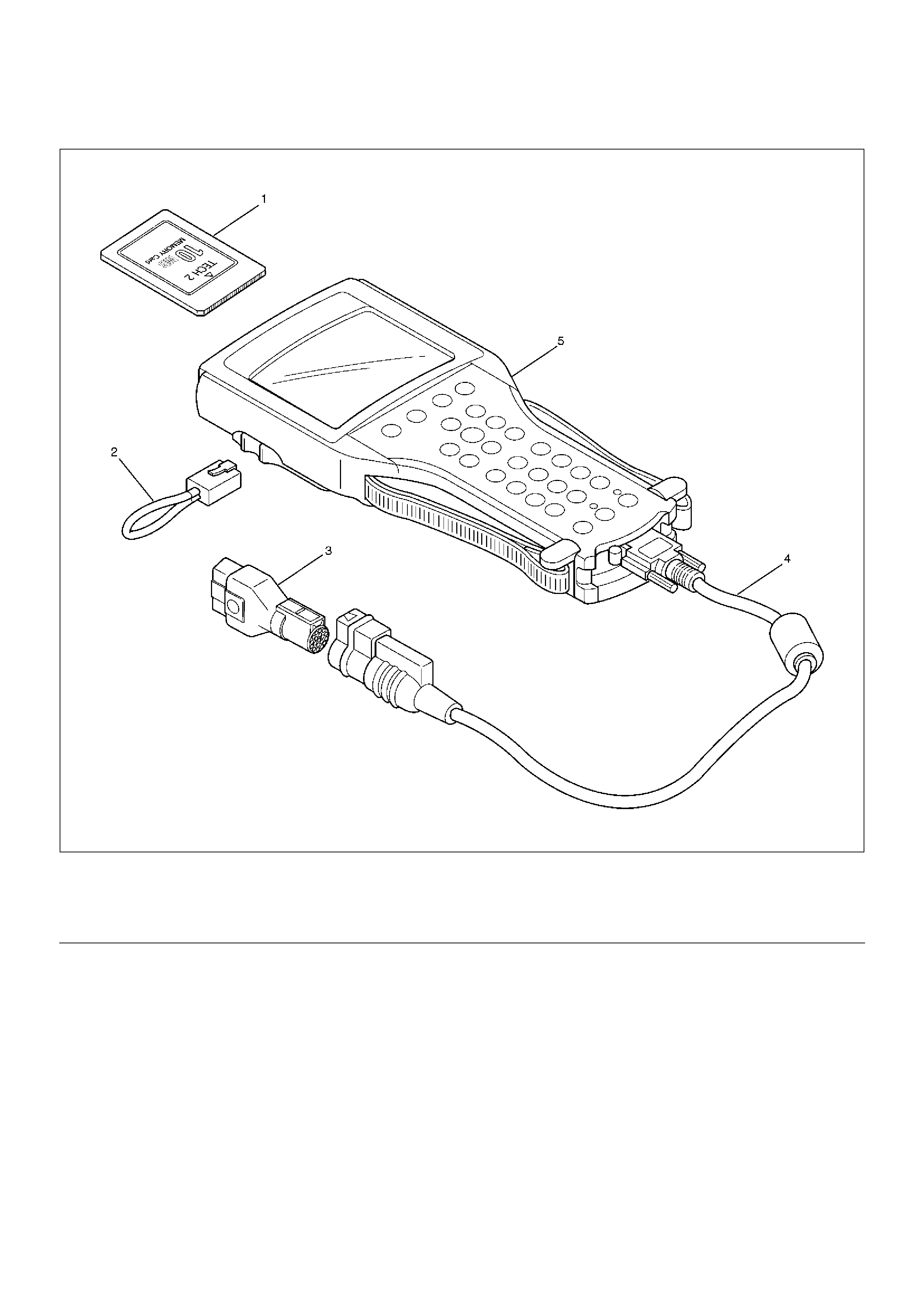
Tech 2 Scan Tool
901RW180
EndOFCallout
Legend
(1) PCMCIA Card
(2) RS 232 Loop Back Connector
(3) SAE 16/19 Adaptor
(4) DLC Cable
(5) Tech–2
Using TECH 2 On The Vehicle
NOTE: Due to the constant evolution of TECH 2
software, the screens shown in this section may
differ slightly from those displayed for the vehicle
being tested.
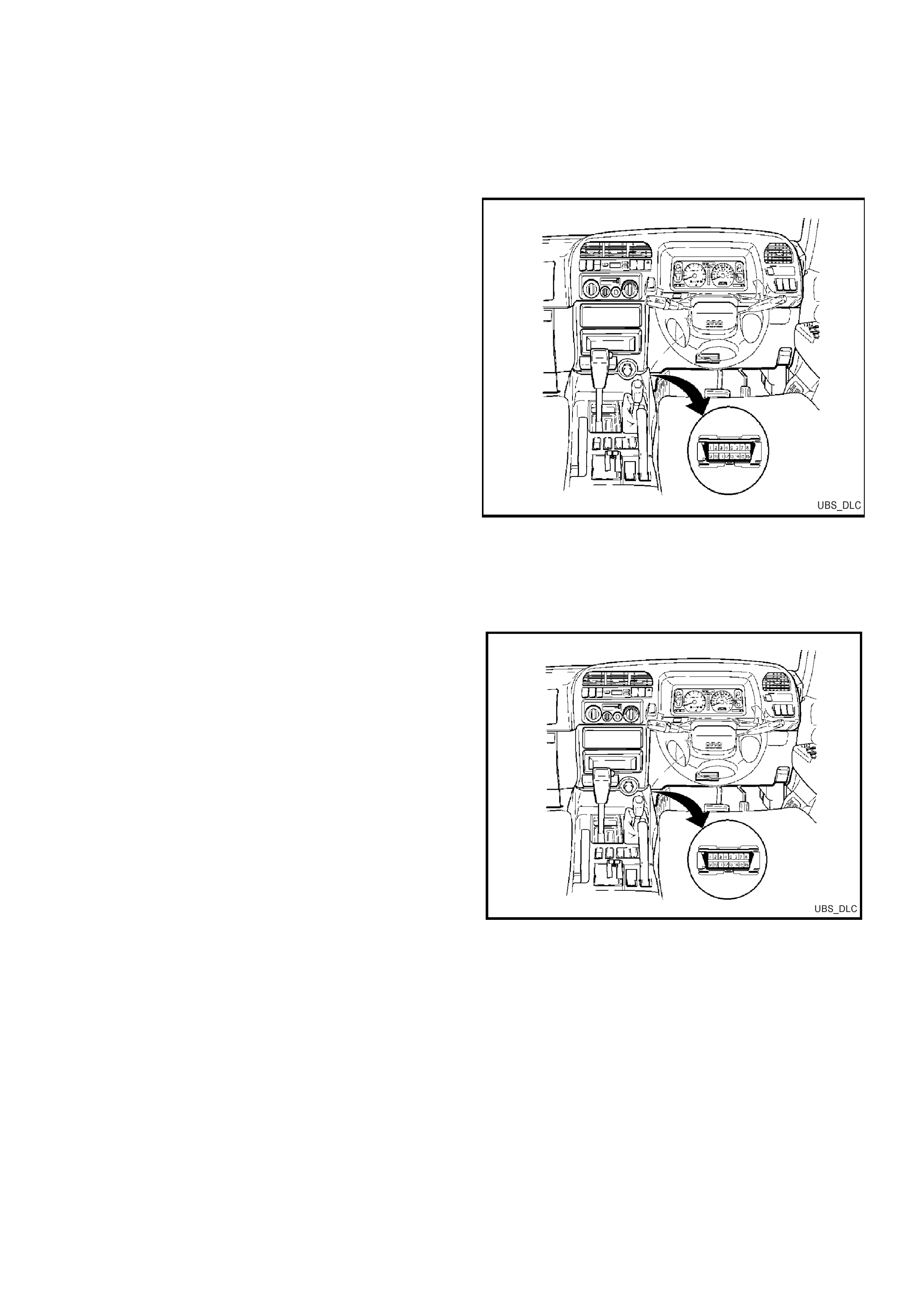
Connecting TECH 2 To The Vehicle
1. Connect Tech 2 to the vehicle DLC, with the DLC
cable and the 16/19 pin adapter.
2. Switch the unit on by pressing the power button (2).
A green light (1) should come on indicating that the
tool is receiving power.
NOTE: At this time the technician should see the Power
On Self Test (POST) run. The POST is a built in
diagnostic self test for the TECH 2 that should find most
common system faults. The POST is run on every
power up to ensure the best operation of the tool. After
the completion of the POST, the TECH 2 unit will briefly
show the POST results. If POST passes, the tool will
continue onto the title screen. If POST fails, results of all
tests will be displayed, and this should show which test
failed. POST failures may be classified as fatal or non-
fatal. A fatal error will not allow the user to continue
using the tool. Failure of the keypad would be an
example of a fatal error. Non-fatal errors found during
the POST will allow continued use of the TECH 2, but
with some limitations. If either a fatal or non-fatal error
occurs, refer to the Troubleshooting section of the
TECH 2 User's Guide.
1. Power Status Indicator Light
2. PWR (Power) Key
3. SHIFT Key
4. SHIFT Key Status Indicator Light
3. At the Tech 2 title screen press the ENTER key to
continue.
4. A selection can be made from the Main Menu,
either by using a function key or by using the arrow
keys to highlight a menu choice and pressing
ENTER.

•NOTE: You will then need to supply some additional
information to the TECH 2. This requires navigation
through a series of lists (called picklists). On some
menus or picklists, the user can use a function key to
make a menu selection, but most of the picklists
require using the selection and action keys. If a
mistake is made in the selection process, or if a
different application or function is desired, press EXIT
to back up one level. Within an application, there may
be soft keys which are available for use. These soft
keys allow access to additional tool functions without
exiting a current tool function. Soft keys are made up
of sets which will appear together. To see the next set
of soft keys, select the More soft key.
The TECH 2 Main Menu contains the following:
F0: Diagnostics
Contains all functions to test, diagnose, monitor and
program the different vehicle systems.
F1: Service Programming System (SPS)
SPS is used in conjunction with Technical
Information System (TIS) 2000 to program vehicle
control units.
F2: View Capture Data
Contains all functions to work with one or two
previously recorded snapshots on one or two
vehicles. This function is to enable the viewing of
captured data without a vehicle.
F3: Tool Options
Contains the TECH 2 self test, set clock, set units,
set screen contrast and Getting Started.
F4: Download/Upload Help
Contains help information on the downloading and
uploading from the TECH 2 to the TIS 2000 CD-
ROM.
Main Menu
UBS2000a
F0: Diagnostics
F1: Service Programming System (SPS)
F2: View Capture Data
F3: Tool Options
F4: Download/Upload Help
5. Select the correct Model Year with the arrow keys
and the press ENTER. The Vehicle identification
screen will then be displayed.
6. Select the correct Vehicle Type with the arrow keys
and the press ENTER. The System Select Menu
will then be displayed.
7. The desired system can be selected from the
System Select Menu with the function keys or with
arrow keys and then press ENTER.
F0:Powertrain contains all functions to test,
diagnose, and monitor the engine and transmission
systems that communicate with the Tech 2 via the
Powertrain Control Module (PCM).
F1: Chassis contains all functions to test,
diagnose, monitor the vehicles chassis systems;
TOD and ABS modules.
F2: Body contains all functions to test, diagnose,
monitor the instruments and Supplemental
Restraint System.
Main Menu
Select one of the following
Model Year(s)
UBS2001a
(2)
(1)
(Y)
(X)
(W)
(2)
2002
2001
2000
1999
1998
1 / 5
2002
Main Menu
Select one of the following
Vehicle Type(s)
Frontera
Jackaroo
Rodeo
VX Commodore
VU Utility
WH Statesman & Caprice
Corsa-B
Corsa-C
Astra-F
Astra-G
Jackaroo
2 / 10
UBS2001
System Select Menu
(2) 2002 Jackaroo
F0: Powertrain
F1: Chassis
F2: Body
UBS2002
Chassis Application Menu Torque On
Demand (TOD)
1. Select the correct chassis system from the Vehicle
Identification menu with the arrow keys, then
press ENTER and follow the instructions on the
screen.
2. Turn on the ignition and press the Confirm soft key.
3. The System identification screen will then display
the control module Part number and System type.
Press the Confirm soft key, and the TOD application
menu will then be displayed.
The following functions are available in the TOD chassis
application menu:
F0: Diagnostic Trouble Codes
F1: Data Display
F2: Snapshot
Vehicle Identification
Select one of the following
Chassis
ABS
TOD
TOD
2 / 2
UBS2009
Chassis
(2) 2002 Jackaroo
Electronic System: TOD
Turn Ignition On!
UBS2009a
Confirm
Chassis
(2) 2002 Jackaroo
Electronic System: TOD
Part Number
Identifier
972047910
903
Part Number
UBS2009b
Confirm

TOD TECH 2 Functions
F0: DIAGNOSTIC TROUBLE CODES
In this test mode, DTC(s) stored by the TOD Module can be displayed or cleared. There are two modes:
F0: Read Current DTC: All current DTC(s) will be displayed.
F1: Clear Current DTC: Clears all current DTC(s) in the PCM memory.
F1: DATA DISPLAY
This mode TECH 2 continuously monitors and displays all TOD data parameters.
F2: SNAPSHOT
In this test mode, the TECH 2 scan tool captures data before and after a snapshot triggering condition which may or
may not set a DTC.
060RY027

060RY00269Diagnostic Trouble Codes
TPS : Throttle Position Sensor
EMC : ElectroMagnetic Coil
ADC : Axle DisConnect (Shift On the Fly)
D-G MAP : Engine type
Flash
DTC
Tech2
DTC
Item Diagnosis Check flow No.
12 — Start code Normal —
13 P1735 Ref Shorted GND 6
14 P1731 Front speed sensor Input abnormality (open, sig or com) 2
15 P1736 Ref Shorted VB6
16 P1737 Front speed sensor Input abnormality 3
21 P1716 TPS Abnormal input — Wiring harness failure 7
23 — ECU CPU abnormality 1
24 P1733 Rear speed sensor Input abnormality (open, sig or com) 5
25 — CHECK lamp Shorted 14
26 — EMC (+) Shorted GND 10
27 P1738 Rear speed sensor Input abnormality 4
28 P1760 ADC (+) & AXLE SW Output abnormality 11
31 P1721 EMC (+) Shorted or disconnected coil/wiring 9
32 P1761 ADC (+) Shorted or disconnected coil/wiring 12
33 P1762 ADC (+) Shorted GND 13
34 — D-G MAP Input abnormality 8
35 — CHECK lamp Shorted or disconnected wiring 14
36 — ECU CPU abnormality 1
37 P1712 ECU CPU abnormality 1
38 P1714 ECU CPU abnormality 1

Diagnosis from Trouble Codes
• Diagnose the TOD based on the fault that has been
saved to the control unit according to the system
self-diagnostic function.
Check flow Trouble code fault Standard
1 23, 36,
37(P1712),
38(P1714)
The ECU has failed. —
Step Action Yes No
1 Turn on the starter switch.
Is the trouble reproduced?
Replace the
ECU and
conduct the test
run.
Go to Step 3 Go to Step 2
2 1. Clear the trouble codes.
2. Conduct the test run.
Is the trouble reproduced during the test run?
Replace the
ECU and
conduct the test
run.
Go to Step 3
The trouble is
not reproduced.
Refer to
“Intermittent
Failures”.
3 1. Check that all the parts are mounted.
2. Clear the trouble codes.
Is this step complete?
Repeat
the“Diagnosis
Flow”. Return to Step 3
NOTE: The following procedure shows the case that
the front or rear sensor reference or common grounding
line is broken.
D04RY00059
Check flow Trouble code fault Standard
214
(P1733)
Front speed sensor signal open or
GND short, speed sensor com open.
0.3V > sensor voltage

Step Action Yes No
1 1. Start the engine.
2. Select TOD mode.
Is there the memory except DTC 14(P1731)? Go to Step 4 Go to Step 2
2 1. Turn off the starter switch.
2. Disconnect the ECU connector (B–67) and (B–68).
Is there the continuity between the connector (B–68) terminal 12
and connector (B–67) terminal 11?
Repair the
circuit.
Go to Step 7 Go to Step 3
3 1. Disconnect the transfer connector (A–3).
Is there the continuity between the connector (B–68) terminal 12
and the connector (A–3) terminal 6, the connector (B–67)
terminal 7 and connector (A–3) terminal 2, and the connector (B–
67) terminal 10 and connector (A–3) terminal 10?
Replace the
front speed
sensor.
Go to Step 7
Repair the
circuit.
Go to Step 7
4 Is the memory DTC 24(P1733)?
Go to Step 5
Refer to other
trouble check flow.
5 Is there the continuity between harnesses of terminal 24 and 23
(vehicle side terminal of the front and rear speed sensor)?
Go to Step 6
Repair the
circuit.
Go to Step 7
6 Is there the continuity between harnesses of terminal 18 and 15
(vehicle side terminal of the speed sensor COM(-) and ref)?
Replace front
and rear speed
sensor.
Go to Step 7
Repair the
circuit.
Go to Step 7
7 1. Check that all the parts are mounted.
2. Clear the trouble code.
Is the step complete? Verify the repair. Return to Step 7
NOTE: Find the trouble in which the pulse
corresponding to the running speed is not input.
D04RY00059
Check flow Trouble code fault Standard
316
(P1737)
The front speed sensor no pulse. Hi level : 4.5 ~ 6.0 V
Lo level : 0.7 ~ 2.0 V
Frequency (F) =
700–850 Hz (at 50 km/h)

Step Action Yes No
1 1. Connect TECH 2.
While running in TOD mode, does TECH–2's front speed sensor
indication change with vehicle speed?
Go to Step 2
Repair and
inspection front
speed sensor
tone wheel.
Go to Step 6
2 1. Clear the trouble code.
While running at 40 km/h or 25 mph in TOD mode for 30
consecutive sec, is the trouble code reissued?
Go to Step 3
The trouble is
not reproduced.
Refer to
“Intermittent
Failures”
3 1. Turn off the starter switch.
2. Disconnect the ECU connector (B–67) and (B–68).
Is there the continuity between the connector (B–68) terminal 12
and connector (B–67) terminal 11?
Repair the
circuit.
Go to Step 6 Go to Step 4
4 1. Disconnect the transfer connector (A–3).
Is there the continuity between the connector (B–68) terminal 12
and the connector (A–3) terminal 6, the connector (B–67)
terminal 7 and connector (A–3) terminal 2, and the connector (B–
67) terminal 10 and connector (A–3) terminal 10?
Replace the
front speed
sensor.
Go to Step 5
Repair the
circuit.
Go to Step 5
5 1. Clear the trouble code.
While running at 40 km/h or 25 mph in TOD mode for 30
consecutive sec, is the trouble code reissued?
1.Replace
ECU.
2.Go to Step 6 Go to Step 6
6 1. Check that all the parts are mounted.
2. Clear the trouble code.
Is this step complete?
Repeat
the“Diagnosis
Flow”. Return to Step 6

NOTE: Find the trouble in which the pulse
corresponding to the running speed is not input.
D04RY00059
Check flow Trouble code fault Standard
427
(P1738)
The rear speed sensor no pulse. Hi level : 4.5 ~ 6.0 V
Lo level : 0.7 ~ 2.0 V
Frequency (F) =
700–850 Hz (at 50 km/h)

Step Action Yes No
1 1. Connect TECH 2.
While running in TOD mode, does TECH–2's rear speed sensor
indication change with vehicle speed?
Go to Step 2
Inspect and
Repair front
speed sensor
tone wheel.
Go to Step 6
2 1. Clear the trouble code.
While running at 40 km/h or 25 mph in TOD mode for 30
consecutive sec, is the trouble code reissued?
Go to Step 3
The trouble is
not reproduced.
Refer to
“Intermittent
Failures”
3 1. Turn off the starter switch.
2. Disconnect the ECU connector (B–67) and (B–68).
Is there the continuity between the connector (B–68) terminal 11
and connector (B–67) terminal 11?
Repair the
circuit.
Go to Step 5 Go to Step 4
4 1. Disconnect the transfer connector (A–3).
Is there the continuity between the connector (B–68) terminal 11
and the connector (A–3) terminal 5, the connector (B–67)
terminal 7 and connector (A–3) terminal 1, and the connector (B–
67) terminal 10 and connector (A–3) terminal 9?
Replace the
rear speed
sensor.
Go to Step 5
Repair the
circuit.
Go to Step 5
5 1. Clear the trouble code.
While running at 40 km/h or 25 mph in TOD mode for 30
consecutive sec, is the trouble code reissued?
Replace ECU.
Go to Step 6 Go to Step 6
6 1. Check that all the parts are mounted.
2. Clear the trouble code.
Is this step complete?
Repeat
the“Diagnosis
Flow”. Return to Step 6
NOTE: The following procedure shows the case that
the front or rear sensor reference or common grounding
line is broken.
D04RY00059
Check flow Trouble code fault Standard
524
(P1733)
Rear speed sensor signal open or
GND short, speed sensor COM
open.
0.3V > sensor voltage

Step Action Yes No
1 1. Start the engine.
2. Select TOD mode.
Is there the memory except DTC 24(P1733)? Go to Step 4 Go to Step 2
2 1. Turn off the starter switch.
2. Disconnect the ECU connector (B–67) and (B–68).
Is there the continuity between the connector (B–68) terminal 11
and connector (B–67) terminal 11?
Repair the
circuit.
Go to Step 7 Go to Step 3
3 1. Disconnect the transfer connector (A–3).
Is there the continuity between the connector (B–68) terminal 11
and the connector (A–3) terminal 5, the connector (B–67)
terminal 7 and connector (A–3) terminal 1, and the connector (B–
67) terminal 10 and connector (A–3) terminal 9?
Replace the
rear speed
sensor.
Go to Step 7
Repair the
circuit.
Go to Step 7
4 Is the memory DTC 14(P1731)?
Go to Step 5
Refer to other
trouble check flow.
5 Is there the continuity between harnesses of terminal 24 and 23
(vehicle side terminal of the front and rear speed sensor)?
Go to Step 6
Repair the
circuit
Go to Step 7
6 Is there the continuity between harnesses of terminal 18 and 15
(vehicle side terminal of the speed sensor COM(-) and ref)?
Replace front
and rear speed
sensor.
Go to Step 7
Repair the
circuit.
Go to Step 7
7 1. Check that all the parts are mounted.
2. Clear the trouble code.
Is the step complete? Verify the repair Return to Step 7
NOTE: If the reference wire (15) is short-circuited to
GND, the speed signal is not generated. If the wire is
short-circuited to the battery voltage, the signal level
becomes faulty.
D04RY00059
Check flow Trouble code fault Standard
613
(P1735)
The reference is short-circuited to
GND.
Reference ` 5 V
15
(P1736)
The reference is short-circuited to
Vb.

Step Action Yes No
1 1. Start the engine.
Does the voltage between terminals 15 and 19 meet the standard
5V?
The trouble is
not reproduced.
Refer
to“Trouble
intermittently
boserved”.
Or verify repair. Go to Step 2
2 Is the voltage below the standard? Go to Step 3 Go to Step 7
3 1. Turn off the starter switch.
2. Disconnect the ECU connector.
Is the continuity established between vehicle harness terminals
(B–67)7 and (B–67)11? Go to Step 4
The ECU is
failed. Replace
the ECU.
Go to Step 8
4 1. Disconnect the H-49 connector.
Is the continuity established between floor harness connector
terminals (H-49)3 and (H-49)9?
Go to Step 5
Short to GND
between (B–
67)7 and (H–
49)3.
Repair the
circuit.
Go to Step 8
5 1. Disconnect the A–3 connector.
Is the continuity established between transfer harness connector
terminals (A–3)2 and (A–3)7?
Replace the
front speed
sensor.
Go to Step 8
The reference
harness for the
front speed
sensor is short–
circuited to
GND. Repair
the circuit.
Go to Step 6
6 1. Disconnect the A–3 connector.
Is the continuity established between transfer harness connector
terminals (A–3)1 and (A–3)7?
Replace the
rear speed
sensor.
Go to Step 8
The reference
harness for the
rear speed
sensor is short–
circuited to
GND. Repair
the circuit.
Go to Step 8
7 1. Turn off the starter switch.
2. Disconnect the ECU connector.
3. Turn on the starter switch.
Is the battery voltage observed between harness connector
terminals (B–67)7 and (B–67)11?
Repair the
harness circuit.
Go to Step 8
The ECU has
failed. Replace
the ECU.
Go to Step 8
8 1. Check that all the parts are mounted.
2. Clear the trouble code.
Is this step complete?
Repeat the
“Diagnosis Flow” Go to Step 8
NOTE: The signal voltage from the TPS deviates from
the standard range.
D04RY00053
Check flow Trouble code fault Standard
721
(P1716)
The voltage of the throttle position
sensor (TPS) is faulty.

Step Action Yes No
1 1. Turn off the starter switch.
Is the battery voltage normal?
Go to Step 2
Charge or
replace the
battery.
Go to Step 6
2 1. Turn on the starter switch.
Does the voltage between terminals 21 and 19 fall within the
standard range above? Go to Step 3 Go to Step 3
3 1. Turn off the starter switch.
2. Disconnect the ECU connector.
3. Turn on the starter switch.
Does the voltage between terminals (B–68)9 and (B–67)11 fall
within the standard range above?
The ECU has
failed. Replace
the ECU.
Go to Step 6 Go to Step 4
4 Is the harness healthy?
Go to Step 5
Repair the
harness.
Go to Step 6
5 Is the TPS healthy?
Go to Step 6
Replace the
TPS.
Go to Step 6
6 1. Check that all the parts are mounted.
2. Clear the trouble code.
Is this step complete?
Repeat
the“Diagnosis
Flow”. Go to Step 6
NOTE: The engine identification signals of 6VE1 and
4JX1 are changed each other.
D04RY00053
Check flow Trouble code fault Standard
8 34 The diesel/gasoline engine
identification signal is faulty.
6VE1: Continuity established
4JX1: No continuity

6VE1
4JX1
Step Action Yes No
1 1. Turn off the starter switch.
Is the continuity established between terminals 14 and 19?
Go to Step 2
The harness is
broken. Repair
the circuit.
Go to Step 3
2 1. Turn on the starter switch.
Does the voltage between terminals 14 and 19 indicate 0V?
The fault is not
reproduced. Refer
to “Intermittent
Failures”
The ECU has
failed. Replace
the ECU.
Go to Step 3
3 1. Check that all the parts are mounted.
2. Clear the trouble code.
Is this step complete?
Repeat
the“Diagnosis
Flow”. Return to Step 3
Step Action Yes No
1 1. Turn off the starter switch.
Is the continuity established between terminals 14 and 19?
The harness for
terminal 14 is
short-circuited
to GND.
Repair the
circuit.
Go to Step 3 Go to Step 2
2 1. Turn on the starter switch.
Does the voltage between terminals 14 and 19 indicate 5V?
The fault is not
reproduced.
Refer to
“Intermittent
Failures”
The ECU has
failed. Replace
the ECU.
Go to Step 3
3 1. Check that all the parts are mounted.
2. Clear the trouble code.
Is this step complete?
Repeat
the“Diagnosis
Flow”. Return to Step 3
D04RY00060
Check flow Trouble code fault Standard
931
(P1721)
The electromagnetic coil is broken or
shorted to the battery or GND.
—

Step Action Yes No
1 1. Clear the trouble code.
2. Start the engine
3. Set the TOD mode.
Is there DTC31 (P1721)? Go to Step 2
Refer to “Trouble
intermittently
observed”.
2 1. Turn off the starter switch.
2. Disconnect the ECU connector from ECU.
Is the continuity established between terminals (B–67)4 and (B–
67)12? Go to Step 3 Go to Step 5
3 1. Connect the ECU connector.
2. Start the engine.
3. Set the TOD mode.
Does the voltage between terminals 4 and 20 indicate at least
0.4V? Go to Step 4 Go to Step 6
4 Is the battery voltage always observed between terminals 4 and
20?
The harness is
short–circuited
on the battery.
Repair the
circuit.
Go to Step 8 Go to Step 6
5 1. Disconnect the A–3 connector.
Is the continuity established between transfer connector
terminals (A–3)8 and (A–3)7? The harness is
broken. Repair
the circuit.
Go to Step 8
Replace the
transfer
electromagnetic
coil (solenoid
clutch).
Go to Step 8
6 1. Turn off the starter switch.
2. Disconnect the ECU connector from ECU.
Is the resistance between the connector (B–67) terminal 4 and 12
1.0 ~ 5.0W?
The ECU has
failed. Replace
the ECU
Go to Step 8 Go to Step 7
7 Is the resistance between the transfer connector (A–3) terminal 8
and 7 1.0 ~ 5.0W?
The harness is
disconnection
or short to
GND. Repair
the circuit.
Go to Step 8
Replace the
transfer
electromagnetic
coil (solenoid
clutch).
Go to Step 8
8 1. Check that all the parts are mounted.
2. Clear the trouble code.
Is this step complete?
Repeat
the“Diagnosis
Flow”. Return to Step 8

D04RY00060
Check flow Trouble code fault Standard
10 26 The electromagnetic coil is
short-circuited to GND.
Resistance: 1.0 to 5.0 ohm (at ordinary
temperature)

Step Action Yes No
1 1. Turn off the starter switch.
2. Disconnect the ECU connector from ECU.
Does the resistance between terminals (B–67)4 and (B–67)12?
indicate 1.0 to 5.0 ohm? Go to Step 2 Go to Step 3
2 1. Connect the ECU connector.
2. Start the engine.
3. Set the TOD mode.
When the throttle is operated between full close and full open
positions, does the voltage between terminals 4 and 20 indicate
0.1 to 1.0 V?
The fault is not
reproduced.
Refer to
“Intermittent
Failures”
The ECU has
failed. Replace
the ECU.
Go to Step 4
3 Does the resistance between transfer connector terminals (A–3)8
and (A–3)7 indicate 1.0 to 5.0ohm? The harness is
broken. Repair
the circuit.
Go to Step 4
Replace the
transfer
electromagnetic
coil.
Go to Step 4
4 1. Check that all the parts are mounted.
2. Clear the trouble code.
Is this step complete?
Repeat
the“Diagnosis
Flow”. Return to Step 4
NOTE: The shift on the fly system is not changed
between 2WD and 4WD modes normally.
CAUTION: If code 32 or 33 is also observed,
remove the trouble associated with code 32 or 33
first.
D04RY00061
Check flow Trouble code fault Standard
11 28
(P1760)
Shift On the Fly (SOF)
system failure
—
D04RY00062

Step Action Yes No
1 1. Turn on the starter switch.
2. Set the transfer to the 2H mode.
Is the battery voltage observed between terminals 5 and 19? Go to Step 2 Go to Step 5
2 Is 5V observed between terminals 10 and 19? Go to Step 3 Go to Step 6
3 1. Set the transfer to the high (TOD) mode.
Does the voltage between terminals 5 and 19 indicate 0V?
Go to Step 4
The ECU has
failed. Replace
the ECU.
Go to Step 7
4 Does the voltage between terminals 10 and 19 indicate 0V? The fault is not
reproduced.
Refer to
“Intermittent
Failures”
Shift On the Fly
(SOF)
system failure
5 Does the TOD indicator show the 2H mode?
The ECU has
failed. Replace
the ECU.
Go to Step 7
See“Trouble
Diagnosis
Depending on The
Status of TOD
Indicator”.
6 Set the transfer to the high (TOD) mode.
Does the voltage between terminals 5 and 19 indicate 0V?
Shift On the Fly
(SOF)
system failure
The ECU has
failed. Replace
the ECU.
Go to Step 7
7 1. Check that all the parts are mounted.
2. Clear the trouble code.
Is this step complete?
Repeat
the“Diagnosis
Flow”. Return to Step 7

NOTE: The on/off signal line of the Shift On the Fly
system is broken, or the line is short–circuited to the
battery.
D04RY00061
Check flow Trouble code fault Standard
12 32
(P1761)
The on/off signal (ADC) line of the
shift on the fly system (front axle
disconnect) is broken, or the line is
short-circuited to the battery.
—

D04RY00062

Step Action Yes No
1 1. Turn off the starter switch.
2. Disconnect the ECU connector from ECU.
Is the continuity established between terminals (B–67)5 and (B–
67)11? Go to Step 2
The harness is
broken. Repair
the circuit.
Go to Step 3
2 Does the voltage between terminals (B–67) 5 and (B–67) 11
indicate 0V?
Go to Step 3
The battery is
short-circuited.
Repair the
circuit.
Go to Step 4
3 1. Turn off the starter switch.
2. Connect ECU connector.
3. Turn on the starter switch.
4. Set the transfer to the 2H mode.
Is the battery voltage observed between terminals 5 and 19?
The fault is not
reproduced
Refer to
“Intermittent
Failures”
The ECU has
failed. Replace
the ECU.
Go to Step 4
4 1. Check that all the parts are mounted.
2. Clear the trouble code.
Is this step complete?
Repeat
the“Diagnosis
Flow”. Return to Step 4
NOTE:
• The on/off signal line of the Shift On The Fly system
is short–circuited to GND.
• The system enters into the fail-safe mode because of
fusing or system protection.
(If a short–circuit is observed on GND, the output to
the on/off signal line becomes 0V.)
D04RY00061
Check flow Trouble code fault Standard
13 33
(P1762)
The ADC line is short-circuited to
GND.
—

D04RY00062
*Layer short-circuit : The coil is damaged by overcurrent.
Step Action Yes No
1 1. Turn off the starter switch.
2. Disconnect the ECU connector from ECU.
Does the resistance between terminals (B–67) 5 and (B–67) 11
meet the standard, 17<R<25 ohms?
The fault is not
reproduced.
Refer to
“Intermittent
Failures” Go to Step 2
2 Is the resistance between terminals (B–67) 5 and (B–67) 11 R<2
ohms?
The signal line
circuit of the
shift on the fly
system is
short-circuited
to GND. Repair
the circuit.
Go to Step 4 Go to Step 3
3 Is the resistance between terminals (B–67) 5 and (B–67) 11 R=
9±7ohms?
The signal line
circuit of the
shift on the fly
system is layer
short-circuited*.
Replace the
valve (VSV).
Go to Step 4 Go to Step 4
4 1. Check that all the parts are mounted.
2. Clear the trouble code.
Is this step complete?
Repeat
the“Diagnosis
Flow”. Return to Step 4

D04RY00063
Check flow Trouble code fault Standard
14 25 The CHECK lamp indicator line is
short–circuited to the battery.
—
35 The line is broken or short–circuited
to GND.
—

Step Action Yes No
1 1. Turn on the starter switch.
Is the CHECK lamp always turned on? Go to Step 2 Go to Step 3
2 1. Turn off the starter switch.
2. Disconnect the ECU connector.
3. Turn on the starter switch.
Is the CHECK lamp always turned on?
The CHECK
circuit is
short-circuited
to GND. Repair
the circuit.
Go to Step 7
The ECU has
failed. Replace
the ECU.
Go to Step 7
3 Turn on the starter switch.
Is the CHECK lamp always turned off? Go to Step 4 Go to Step 6
4 Turn on the starter switch.
Is the battery voltage observed between terminals 30 and 19?
Go to Step 5
The CHECK
circuit wires are
broken or the
CHECK lamp is
failed. Repair
the circuit.
Go to Step 7
5 Turn off the starter switch.
Is the battery voltage observed between terminals 30 and 19?
The battery is
short–circuited.
Repair the
CHECK lamp
circuit.
Go to Step 7
The ECU has
failed. Replace
the ECU.
Go to Step 7
6 Turn on the starter switch.
Does the CHECK lamp go off two seconds after?
The fault is not
reproduced.
Refer to
“Intermittent
Failures” Go to Step 7
7 1. Check that all the parts are mounted.
2. Clear the trouble code.
Is this step complete?
Repeat
the“Diagnosis
Flow”. Return to Step 7
Trouble Diagnosis Depending on The
Status of TOD Indicator
Functional check with TOD indicator light is conducted
prior to check on Charts A–H.
• After the starter is switched on, check and see if the
status has become as tabulated below.
C07RW012-1
• If the status is as tabulated above, there is no
problem. If not as tabulated above, inspect the
harness.

D04RY00114
D04RY00115
Chart A Indicator drive circuit
Function of circuit The circuit informs the indicator of the working condition of the ECU.
Fail condition All the TOD indicator lamps and CHECK lamp are lit, and go off momentarily at an interval
of about two seconds.
Indicator lamp status
—
Transfer position 2H, TOD, 4L —

Step Action Yes No
1 Turn on the starter switch.
Is the battery voltage observed between terminals 1 and 19?
The ECU has
failed. Replace
the ECU.
Go to Step 2
Check the
battery circuit.
Go to Step 2
2 Check that all the parts are mounted.
Is this step complete?
Repeat
the“Diagnosis
Flow”. Return to Step 2
D04RY00114
D04RY00115
Chart B–1 The 4WD AUTO switch circuit wires are broken or short-circuited to the GND
Function of circuit —
Fail condition Even after the transfer mode is selected from TOD to 2H, the indicator lamp status is not
changed.
Indicator lamp status
—
Transfer position 2H —

Step Action Yes No
1 1. Turn on the starter switch.
When the 4WD SW is selected to the 4WD position, is 0 V
observed between terminal 12 and 19?
Go to Step 2
Repair the 4WD
AUTO SW
circuit.
Go to Step 4
2 When the 4WD AUTO SW is selected to the 2WD position, is 12
V observed between terminals 12 and 19?
Go to Step 3
Repair the 4WD
AUTO SW
circuit.
Go to Step 4
3 When the transfer lever is shifted to the 4L position, is battery
voltage observed between terminals 28 and 19?
The fault is not
reproduced. Refer
to“Troubles
intermittently
observed”.
Replace the
ECU.
Go to Step 4
4 Check that all the parts are mounted.
Is this step complete?
Repeat
the“Diagnosis
Flow”. Return to Step 4
D04RY00114
D04RY00115
Chart B–2 The 4WD AUTO switch circuit is short to battery.
Function of circuit —
Fail condition Even after the transfer mode is selected from 2H to TOD, the indicator lamp status dose
not change.
Indicator lamp status
Transfer position TOD

Step Action Yes No
1 When the 4WD AUTO SW is selected to the 4WD position, is 0 V
observed between terminal 12 and 19?
Go to Step 2
Repair the 4WD
AUTO SW
circuit.
Go to Step 7
2 When the 4WD AUTO SW is selected to the 2WD position, is 12
V observed between terminals 12 and 19?
Go to Step 3
Repair the 4WD
AUTO SW
circuit.
Go to Step 7
3 1. Disconnect the ECU connector.
Is the continuity established between terminals (B–67)1 and (B–
68)13?
Go to Step 4
Replace TOD
indicator lamp
bulb.
Go to Step 7
4 Is the continuity established between terminals (B–67)1 and (B–
68)14?
Go to Step 5
Replace TOD
indicator lamp
bulb.
Go to Step 7
5 Is the continuity established between terminals (B–67)1 and (B–
68)15?
Go to Step 6
Replace TOD
indicator lamp
bulb.
Go to Step 7
6 Is the continuity established between terminals (B–67)1 and (B–
68)16?
Replace ECU.
Go to Step 7
Replace TOD
indicator lamp
bulb.
Go to Step 7
7 Check that all the parts are mounted.
Is this step complete?
Repeat
the“Diagnosis
Flow”. Return to Step 7
D04RY00114
D04RY00115
Chart C–1 4H switch circuit wires are broken or the battery is short-circuited.
Function of circuit —
Fail condition When the 4WD AUTO SW is 4WD mode.
When the lever is shifted from 4L to HIGH, the 4L mode remains on the indicator and the
TOD mode is displayed without turning off the previous mode.
Indicator lamp status
Transfer position 4L <——> Neutral <——> TOD

Step Action Yes No
1 1. Turn on the starter switch.
When the transfer lever is shifted to the high position, is 5V
observed between terminals 8 and 19 (4H switch)? Go to Step 2 Go to Step 4
2 When the transfer lever is shifted to the 4L position, is 5V
observed between terminals 8 and 19 (4H switch)? Go to Step 3 Go to Step 4
3 When the transfer lever is shifted to the neutral position, is 0V
observed between terminals 8 and 19 (4H switch)?
Replace the
ECU.
Go to Step 13 Go to Step 4
4 1. Turn off the starter switch.
2. Disconnect the ECU connector.
3. Turn on the starter switch.
When the transfer lever is shifted to the high position, is 12V
observed between terminals 8 and 19 (4H switch)? Go to Step 5 Go to Step 7
5 When the transfer lever is shifted to the neutral position, is 0V
observed between terminals 8 and 19 (4H switch)? Go to Step 6 Go to Step 7
6 When the transfer lever is shifted to the 4L position, is 12V
observed between terminals 8 and 19 (4H switch)?
The 4H switch
circuit is
short-circuited
between ECU
and transfer on
battery.
Repair the
circuit.
Go to Step 13 Go to Step 7
7 Turn off the starter switch.
When the transfer lever is shifted to the neutral position, is the
continuity established between terminals 8 and 19 (4H switch)? Go to Step 8 Go to Step 10
8 When the transfer lever is shifted to the high position, is the
continuity established between terminals 8 and 19? Go to Step 11 Go to Step 9
9 When the transfer lever is shifted to the 4L position, is the
continuity established between terminals 8 and 19?
Go to Step 12
The ECU has
failed.
Replace the
ECU.
Go to Step 13
10 When the transfer lever is shifted to the neutral position, is the
continuity established between terminals (A–3)4 and (A–3)7?
The 4H switch
circuit is broken
between ECU
and transfer.
Repair the
circuit.
Go to Step 13
Repair the
transfer
assembly.
Go to Step 13
11 When the transfer lever is shifted to the high position, is the
continuity established between transfer connector terminals (A–
3)4 and (A–3)7?
Repair the
transfer
assembly.
Go to Step 13
Repair the 4H
SW circuit.
Go to Step 13
12 When the transfer lever is shifted to the 4L position, is the
continuity established between transfer connector terminals (A–
3)7 and (A–3)4?
Repair the
transfer
assembly.
Go to Step 13
Repair the 4H
SW circuit.
Go to Step 13
13 Check that all the parts are mounted.
Is this step complete?
Repeat
the“Diagnosis
Flow”. Return to Step 13
D04RY00114
D04RY00115
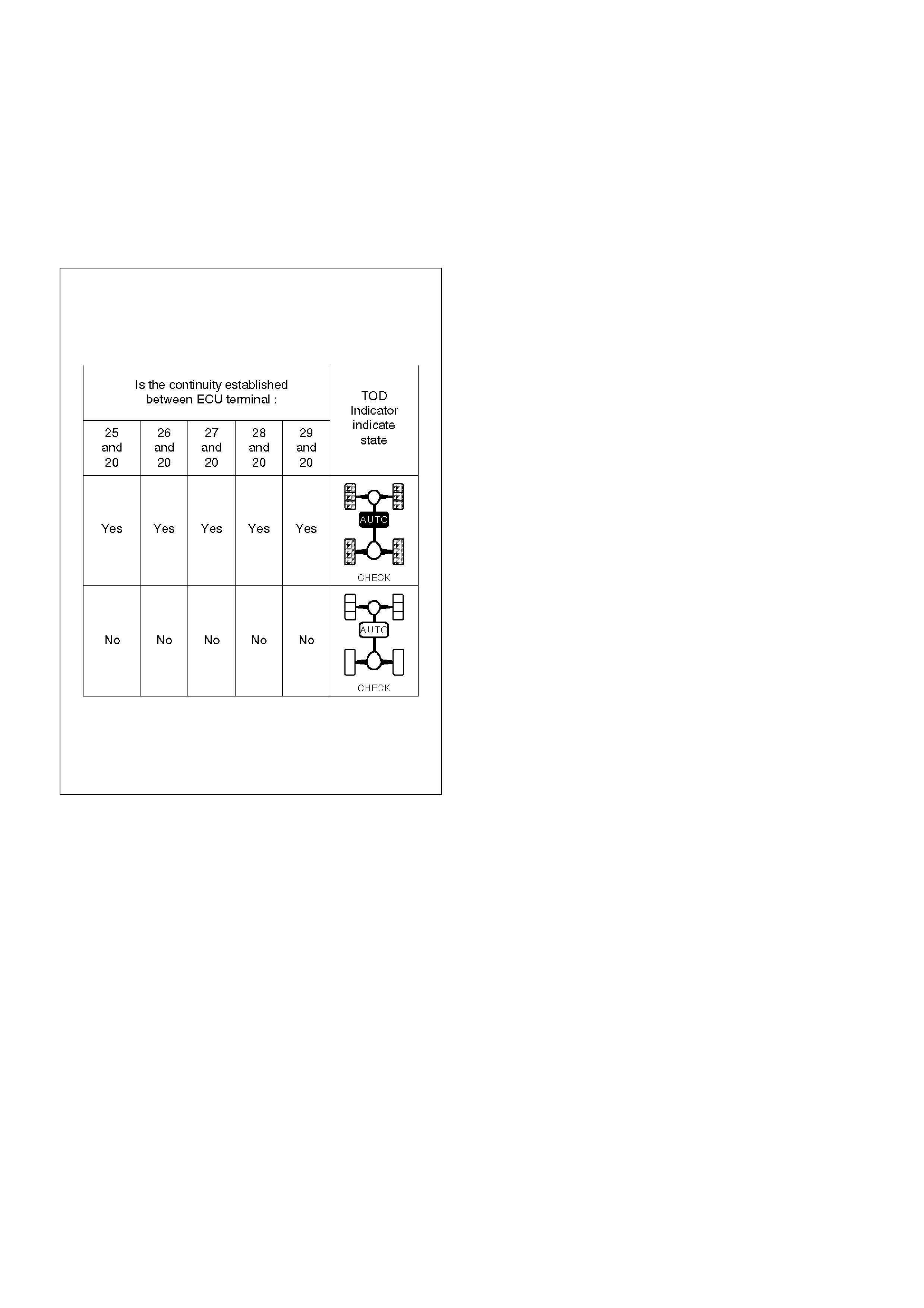
Chart C–2 The 4H switch circuit is short-circuited to GND.
Function of circuit —
Fail condition When the transfer lever is shifted to 4L, the indicator lamp status is not changed.
Indicator lamp status
Transfer position 4L

Step Action Yes No
1 When the transfer lever is shifted to the High position, is 5V
observed between terminals 8 and 19 (4H switch)? Go to Step 2 Go to Step 14
2 When the transfer lever is shifted to the neutral position, is 0V
observed between terminals 8 and 19 (4H switch)? Go to Step 3 Go to Step 14
3 When the transfer lever is shifted to the 4L position, is 5V
observed between terminals 8 and 19 (4H switch)? Go to Step 4 Go to Step 14
4 1. Turn off the starter switch.
Is the continuity established between terminals 1 and 25?
Go to Step 5
Replace TOD
indicator lamp
bulb, or repair
the circuit.
Go to Step 23
5 Is the continuity established between terminals 1 and 26?
Go to Step 6
Replace TOD
indicator lamp
bulb, or repair
the circuit.
Go to Step 23
6 Is the continuity established between terminals 1 and 27?
Go to Step 7
Replace TOD
indicator lamp
bulb, or repair
the circuit.
Go to Step 23
7 Is the continuity established between terminals 1 and 28?
Go to Step 8
Replace TOD
indicator lamp
bulb, or repair
the circuit.
Go to Step 23
8 Is the continuity established between terminals 1 and 29?
Go to Step 9
Replace TOD
indicator lamp
bulb, or repair
the circuit.
Go to Step 23
9 1. Turn on the starter switch.
2. Shift the transfer lever is shifted to the 4L position.
Is 0 V observed between terminals 25 and 20? Go to Step 10
The ECU has
failed. Replace
the ECU.
Go to Step 23
10 Is 0 V observed between terminals 26 and 20?
Go to Step 11
The ECU has
failed. Replace
the ECU.
Go to Step 23
11 Is 0 V observed between terminals 27 and 20?
Go to Step 12
The ECU has
failed. Replace
the ECU.
Go to Step 23
12 Is 12 V observed between terminals 28 and 20?
Go to Step 13
The ECU has
failed. Replace
the ECU.
Go to Step 23
13 Is 0 V observed between terminals 29 and 20? The fault is not
reproduced.
Refer
to“Troubles
intermittently
observed”.
The ECU has
failed. Replace
the ECU.
Go to Step 23

14 1. Turn off the starter switch.
2. Disconnect the ECU connector.
When the transfer lever is shifted to the neutral position, is the
continuity established between terminals (B–68)3 and (B–67)11
(4H switch)? Go to Step 15 Go to Step 17
15 When the transfer lever is shifted to the high position, is the
continuity established between terminals (B–68)3 and (B–67)11? Go to Step 17 Go to Step 16
16 When the transfer lever is shifted to the 4L position, is the
continuity established between terminals (B–68)3 and (B–67)11?
Go to Step 17
The ECU has
failed. Replace
the ECU.
Go to Step 23
17 1. Disconnect the H–49 connector.
When the transfer lever is shifted to the neutral position between
high and 4L, is the continuity established between terminals
(H-49) 6 and (B-67) 11? Go to Step 18 Go to Step 20
18 When the transfer lever is shifted to the high position, is the
continuity established between transfer connector terminals
(H-49) 6 and (B-67) 11? Go to Step 20 Go to Step 19
19 When the transfer lever is shifted to the 4L position, is the
continuity established between transfer connector terminals
(H-49) 6 and (B-67)1 1?
Go to Step 20
GND is
short-circuited
between
terminals (B-68)
3 and (H-49) 6.
Repair the
circuit.
Go to Step 23
20 1. Disconnect the A–3 connector.
When the transfer lever is shifted to the neutral position between
high and 4L, is the continuity established between terminals (A-3)
4 and (A-3) 7? Go to Step 21
Repair the
transfer
assembly.
Go to Step 23
21 When the transfer lever is shifted to the high position, is the
continuity established between terminals (A-3) 4 and (A-3) 7?
Repair the
transfer
assembly.
Go to Step 23 Go to Step 22
22 When the transfer lever is shifted to the 4L position, is the
continuity established between terminals (A-3)4 and (A-3)7?
Repair the
transfer
assembly.
Go to Step 23
GND is
short-circuited
between
terminals
(B-68)3 and (A–
3)4. Repair the
circuit.
Go to Step 23
23 Check that all the parts are mounted.
Is this step complete?
Repeat
the“Diagnosis
Flow”. Return to Step 23
Step Action Yes No
D04RY00054
Chart D–1 4L switch circuit wires are broken or the battery is short-circuited.
Function of circuit —
Fail condition The TOD mode is displayed in the neutral position between high and 4L. When the lever
is shifted to the 4L position, the TOD mode is displayed.
Indicator lamp status
Transfer position 4L Neutral

Step Action Yes No
1 Turn on the starter switch.
When the transfer lever is shifted to the high position, is 5V
observed between terminals 9 and 19 (4L switch)? Go to Step 2 Go to Step 4
2 When the transfer lever is shifted to the neutral position, is 0V
observed between terminals 9 and 19 (4L switch)? Go to Step 3 Go to Step 4
3 When the transfer lever is shifted to the 4L position, is 0V
observed between terminals 9 and 19 (4L switch)?
The ECU has
failed. Replace
the ECU.
Go to Step 13 Go to Step 4
4 1. Turn off the starter switch.
2. Disconnect the ECU connector.
3. Turn on the starter switch.
When the transfer lever is shifted to the high position, is 12V
observed between terminals (B–68)4 and (B–67)11? Go to Step 5 Go to Step 7
5 When the transfer lever is shifted to the neutral position, is 0V
observed between terminals (B–68)4 and (B–67)11? Go to Step 6 Go to Step 7
6 When the transfer lever is shifted to the 4L position, is 0V
observed between terminals (B–68)4 and (B–67)11?
The 4L switch
circuit is
short-circuited
on battery
between ECU
and transfer.
Repair the
circuit.
Go to Step 13 Go to Step 7
7 Turn off the starter switch.
When the transfer lever is shifted to the high position, is the
continuity established between terminals (B–68)4 and (B–67)11? Go to Step 12 Go to Step 8
8 When the transfer lever is shifted to the neutral position between
high and 4L, is the continuity established between terminals (B–
68)4 and (B–67)11? Go to Step 9 Go to Step 10
9 When the transfer lever is shifted to the 4L position, is the
continuity established between terminals (B–68)4 and (B–
67)11?
The fault is not
reproduced.
Refer
to“Troubles
intermittently
observed”. Go to Step 11
10 1. Disconnect the A–3 connector.
When the transfer lever is shifted to the neutral position between
high and 4L, is the continuity established between transfer
connector terminals (A–3)12 and GND?
Wires are
broken between
transfer
connector (A–
3)12 and
connector
(B-68)4.
Repair the
circuit.
Go to Step 13
Repair the
transfer
assembly.
Go to Step 13

11 When the transfer lever is shifted to the 4L position, is the
continuity established between transfer connector terminals (A–
3)12 and GND?
Wires are
broken between
transfer
connector (A–
3)12 and
connector
(B-68)4.
Repair the
circuit.
Go to Step 13
Repair the
transfer
assembly.
Go to Step 13
12 When the transfer lever is shifted to the high position, is the
continuity established between transfer connector terminals (A–
3)12 and GND?
Repair the
transfer
assembly.
Go to Step 13
Wires are
broken between
transfer
connector (A–
3)12 and
connector
(B-68)4.
Repair the
circuit.
Go to Step 13
13 Check that all the parts are mounted.
Is this step complete?
Repeat
the“Diagnosis
Flow”. Return to Step 13
Step Action Yes No
D04RY00064
D04RY00065
Chart D–2 The 4L switch circuit is short-circuited to GND.
Function of circuit —
Fail condition The 4L mode is displayed even in the 2H or TOD.
Indicator lamp status
Transfer position HIGH (2H or TOD)

Step Action Yes No
1 When the transfer lever is shifted to the high position, is 5V
observed between terminals 9 and 19 (4L switch)? Go to Step 2 Go to Step 7
2 When the transfer lever is shifted to the neutral position, is 0V
observed between terminals 9 and 19 (4L switch)? Go to Step 3 Go to Step 7
3 When the transfer lever is shifted to the 4L position, is 0V
observed between terminals 9 and 19 (4L switch)? Go to Step 4 Go to Step 7
4 1. Shift the 4WD AUTO SW to the 2H position.
Is 12V observed between terminals 25 and 19?
Go to Step 5
The ECU has
failed. Replace
the ECU.
Go to Step 16
5 Is 12V observed between terminals 26 and 19?
Go to Step 6
The ECU has
failed. Replace
the ECU.
Go to Step 16
6 Is 12V observed between terminals 27 and 19? The fault is not
reproduced.
Refer to
“intermittent
Failures”
The ECU has
failed. Replace
the ECU.
Go to Step 16
7 1. Turn off the starter switch.
2. Disconnect the ECU connector.
When the transfer lever is shifted to the neutral position between
High and 4L, is the continuity established between terminals (B–
68)4 and (B–67)11? Go to Step 8 Go to Step 10
8 When the transfer lever is shifted to the 4L position, is the
continuity established between terminals (B–68)4 and (B–67)11? Go to Step 9 Go to Step 10
9 When the transfer lever is shifted to the high position, is the
continuity established between terminals (B–68)4 and (B–67)11?
Go to Step 10
The ECU has
failed. Replace
the ECU.
Go to Step 16
10 1. Disconnect the H-49 connector.
When the transfer lever is shifted to the neutral position between
high and 4L, is the continuity established between terminals
(H-49)5 and (B-67)11? Go to Step 11 Go to Step 13
11 When the transfer lever is shifted to the 4L position, is the
continuity established between transfer connector terminals
(H-49)5 and (B-67)11? Go to Step 12 Go to Step 13
12 When the transfer lever is shifted to the high position, is the
continuity established between terminals (H-49)5 and (B-67)11?
Go to Step 13
GND is
short-circuited
between
terminals (B–
68)4 and
(H-49)5. Repair
the circuit.
Go to Step 16
13 1. Disconnect the A-3 connector.
When the transfer lever is shifted to the neutral position between
high and 4L, is the continuity established between terminals
(A-3)12 and GND? Go to Step 14
Repair the
transfer
assembly.
Go to Step 16

14 When the transfer lever is shifted to the 4L position, is the
continuity established between terminals (A-3)12 and GND?
Go to Step 15
Repair the
transfer
assembly.
Go to Step 16
15 When the transfer lever is shifted to the high position, is the
continuity established between terminals (A-3)12 and GND?
Repair the
transfer
assembly.
Go to Step 16
GND is
short-circuited
between
terminals (H–
49)5 and
(A-3)12. Repair
the circuit.
Go to Step 16
16 Check that all the parts are mounted.
Is this step complete?
Repeat
the“Diagnosis
Flow”. Return to Step 16
Step Action Yes No

D04RY00068
Chart E–1 AXLE switch circuit wires are broken.
Function of circuit —
Fail condition Both the TOD and 4L modes are disabled. (The transition status is not removed.)
Indicator lamp status
Transfer position TOD 4L

D04RY00069

D04RY00070
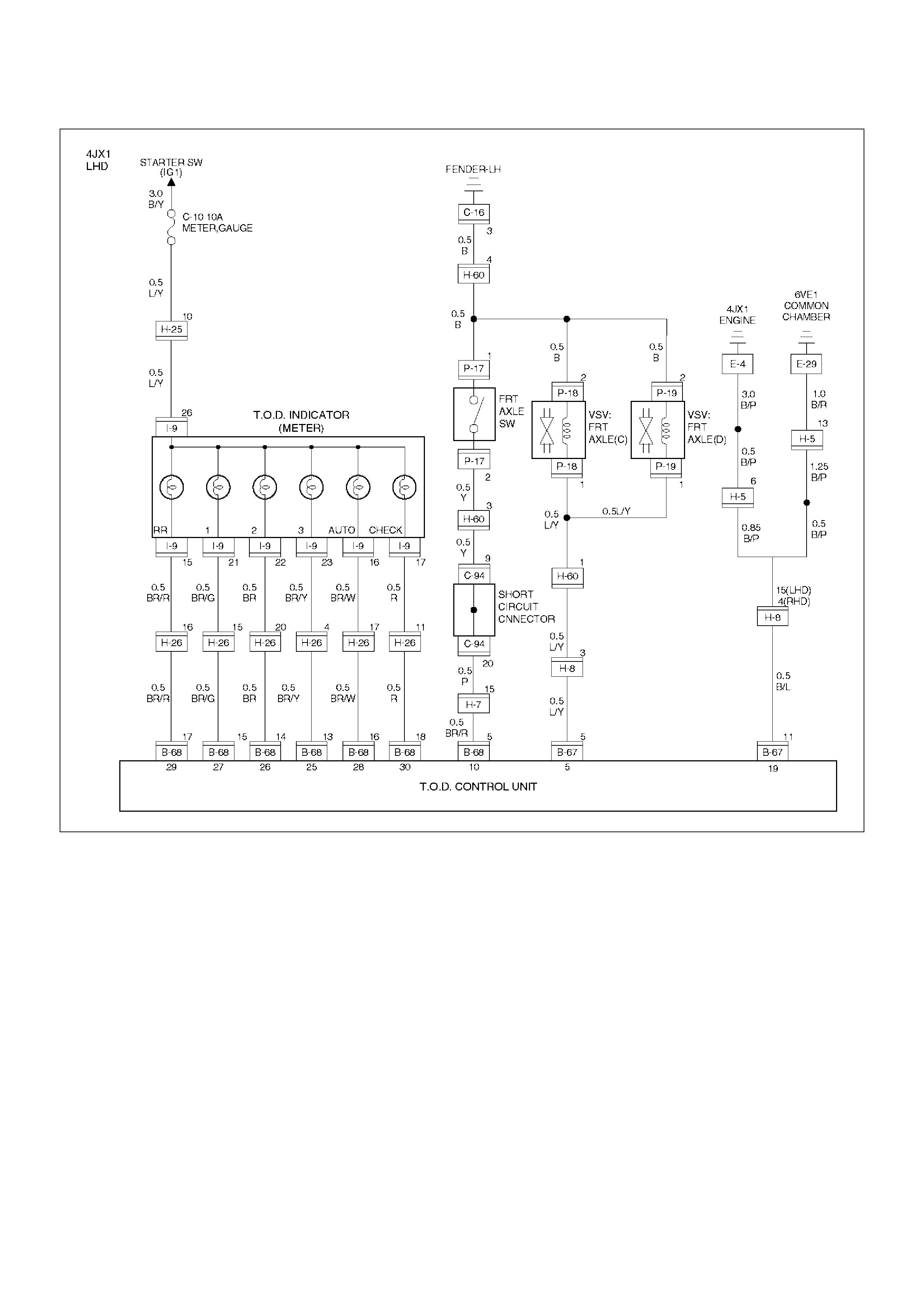
D04RY00071

Step Action Yes No
1 Start the engine.
When the transfer lever is shifted to the neutral position between
high and 4L, is 5V observed between terminals 10 and 19? Go to Step 2 Go to Step 7
2 When the transfer lever is shifted to the high position and 4WD
AUTO SW is selected to the 4WD position, is 0V observed
between terminals 10 and 19? Go to Step 3 Go to Step 7
3 When the transfer lever is shifted to the 4L position, is 0V
observed between terminals 10 and 19?
The ECU has
failed. Replace
the ECU.
Go to Step 4 Go to Step 7
4 Shift the transfer lever to the 4L position.
Is 0V observed between terminals 25 and 19?
Go to Step 5
The ECU has
failed. Replace
the ECU.
Go to Step 19
5 Is 0V observed between terminals 26 and 19?
Go to Step 6
The ECU has
failed. Replace
the ECU.
Go to Step 19
6 Is 0V observed between terminals 27 and 19? The fault is not
reproduced.
Refer to
“intermittent
Failures”
The ECU has
failed. Replace
the ECU.
Go to Step 19
7 When the transfer lever is shifted to the high position and 4WD
AUTO SW is selected to the 2H position, is the battery voltage
observed between terminals 5 and 19? Go to Step 8 Go to Step 11
8 When the transfer lever is shifted to the neutral position between
high and 4L, is the battery voltage observed between terminals 5
and 19? Go to Step 9 Go to Step 11
9 When the transfer lever is shifted to the high position and 4WD
AUTO SW is selected to the 4WD position (TOD mode), is 0V
observed between terminals 5 and 19? Go to Step 10 Go to Step 11
10 When the transfer lever is shifted to the 4L position, is 0V
observed between terminals 5 and 19? Go to Step 12 Go to Step 11
11 Is any of the trouble codes 28, 32 and 33 recorded? Examine the
trouble based
on“Diagnosis
from Trouble
Codes”.
The ECU has
failed. Replace
the ECU.
12 1. Turn off the starter switch.
2. Disconnect the ECU connector.
Does the resistance between terminals (B–67)5 and (B–67)11
meet the standard, 17< R < 25 ohm? Go to Step 13
Repair the
circuit or
replace the
VSV.
Go to Step 19
13 1. Turn on the starter switch.
When the 4WD AUTO SW is selected to the 2WD position, is the
battery voltage supplied to each VSV?
Go to Step 14
Repair the
circuit or
replace the
VSV.
Go to Step 19

14 When the transfer lever is shifted to the neutral position between
high and 4L, is the battery voltage supplied to each VSV?
Go to Step 15
Repair the
circuit or
replace the
VSV.
Go to Step 19
15 When the transfer lever is shifted to the high position and 4WD
AUTO SW is selected to the 4WD position, is 0V observed on
each VSV?
Go to Step 16
Repair the
circuit or
replace the
VSV.
Go to Step 19
16 When the transfer lever is shifted to the 4L position, is 0V
observed on each VSV?
Go to Step 17
Repair the
circuit or
replace the
VSV.
Go to Step 19
17 Is the vacuum pressure supplied to the VSV?
Go to Step 18
Repair the
vacuum
system.
Go to Step 19
18 Can the single AXLE switch enable and disable the continuity? Repair the shift
on the fly
system (refer to
Section 4B1.)
Replace the
AXLE switch
(refer to Section
4B1).
19 Check that all the parts are mounted.
Is this step complete?
Repeat
the“Diagnosis
Flow”. Return to Step 19
Step Action Yes No

D04RY00068
Chart E–2 The AXLE switch circuit is short-circuited to GND.
Function of circuit —
Fail condition Even after the 4WD AUTO SW is select to the 2WD position, the 2WD mode is not
enabled. (The transition status is not removed.)
Indicator lamp status
Transfer position 2H

D04RY00069
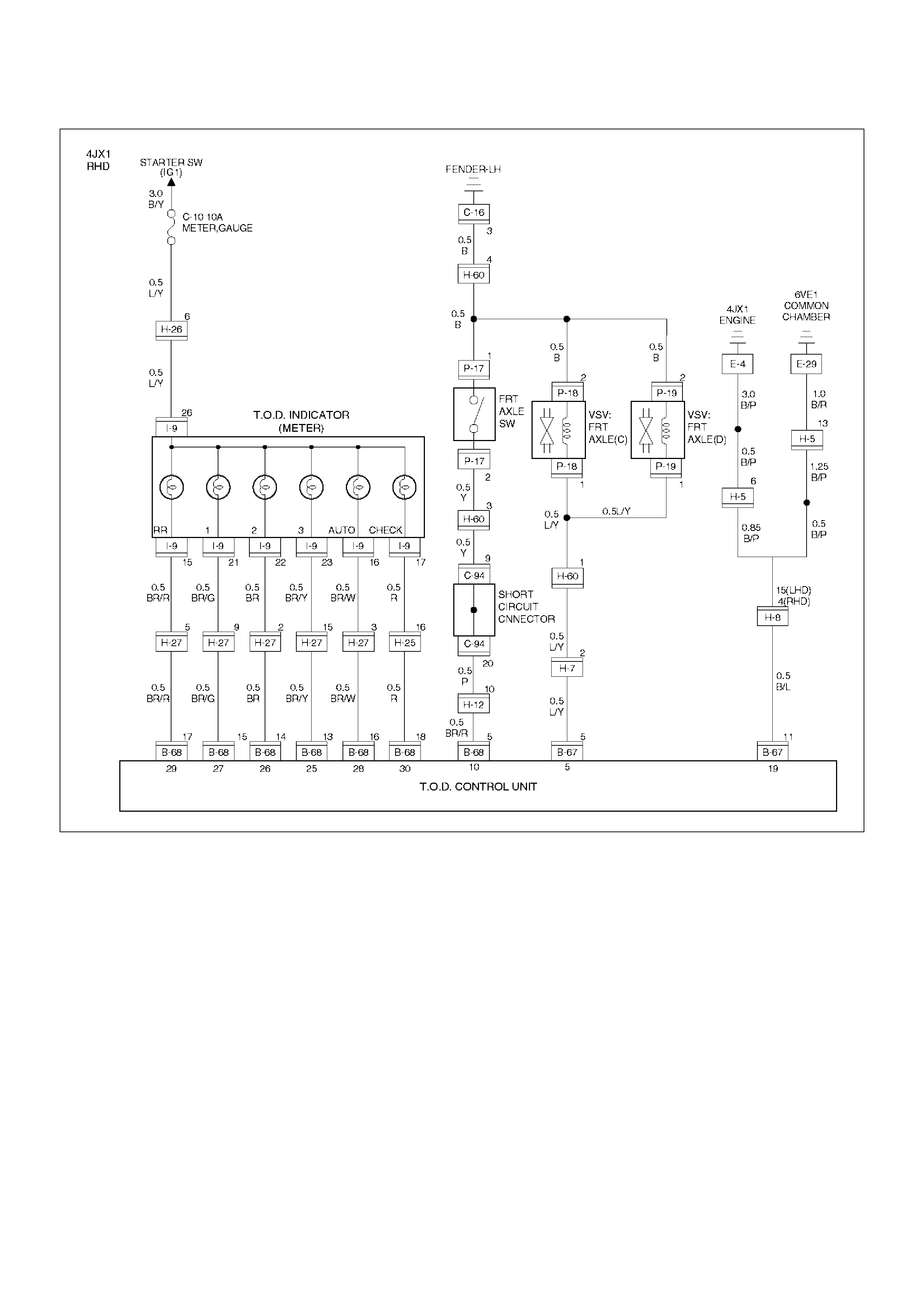
D04RY00070
D04RY00071

Step Action Yes No
1 Start the engine.
When the transfer lever is shifted to the neutral position between
high and 4L, is 5V observed between terminals 10 and 19? Go to Step 2 Go to Step 7
2 When the transfer lever is shifted to the high position and 4WD
AUTO SW is selected to the 4WD position, is 0V observed
between terminals 10 and 19? Go to Step 3 Go to Step 7
3 When the transfer lever is shifted to the 4L position, is 0V
observed between terminals 10 and 19? Go to Step 4 Go to Step 7
4 Select the 4WD AUTO SW to the 2WD position.
Is 12V observed between terminals 25 and 19?
Go to Step 5
Replace the
ECU.
Go to Step 19
5 Is 12V observed between terminals 26 and 19?
Go to Step 6
Replace the
ECU.
Go to Step 19
6 Is 12V observed between terminals 27 and 19? The fault is not
reproduced.
Refer to
“intermittent
Failures”
The ECU has
failed. Replace
the ECU.
Go to Step 19
7 When the 4WD AUTO SW is selected to the 2WD position, is the
battery voltage observed between terminals 5 and 19? Go to Step 8 Go to Step 11
8 When the transfer lever is shifted to the neutral position between
high and 4L, is the battery voltage observed between terminals 5
and 19? Go to Step 9 Go to Step 11
9 When the transfer lever is shifted to the high position and 4WD
AUTO SW is selected to the 4WD position, is 0V observed
between terminals (B–67)5 and (B–67)11? Go to Step 10 Go to Step 11
10 When the transfer lever is shifted to the 4L position, is 0V
observed between terminals 5 and 19? Go to Step 12 Go to Step 11
11 Is any of the trouble codes 28, 32 and 33 recorded? Examine the
trouble based
on“Diagnosis from
Trouble Codes”.
The ECU has
failed. Replace
the ECU.
12 1. Turn off the starter switch.
2. Disconnect the ECU connector.
Does the resistance between terminals 5 and 19 meet the
standard, 17< R < 25 ohm? Go to Step 13
Repair the
circuit or
replace the
VSV.
Go to Step 19
13 1. Connect the ECU connector.
2. Turn on the starter switch.
When the 4WD AUTO SW is selected to the 2WD position, is the
battery voltage supplied to each VSV? Go to Step 14
Repair the
circuit or
replace the
VSV.
Go to Step 19
14 When the transfer lever is shifted to the neutral position between
high and 4L, is the battery voltage supplied to each VSV?
Go to Step 15
Repair the
circuit or
replace the
VSV.
Go to Step 19
15 When the transfer lever is shifted to the high position and 4WD
AUTO SW is selected to the 4WD position, is 0V observed on
each VSV?
Go to Step 16
Repair the
circuit or
replace the
VSV.
Go to Step 19

16 When the transfer lever is shifted to the 4L position, is 0V
observed on each VSV?
Go to Step 17
Repair the
circuit or
replace the
VSV.
Go to Step 19
17 Is the vacuum pressure supplied to the VSV?
Go to Step 18
Repair the
vacuum
system.
Go to Step 19
18 Can the single AXLE switch enable and disable the continuity? Repair the shift
on the fly
system Refer to
Section 4B1
and 4C.
Go to Step 19
Replace the
AXLE switch
Refer to Section
4B1 and 4C.
Go to Step 19
19 Check that all the parts are mounted.
Is this step complete?
Repeat
the“Diagnosis
Flow”. Return to Step 19
Step Action Yes No
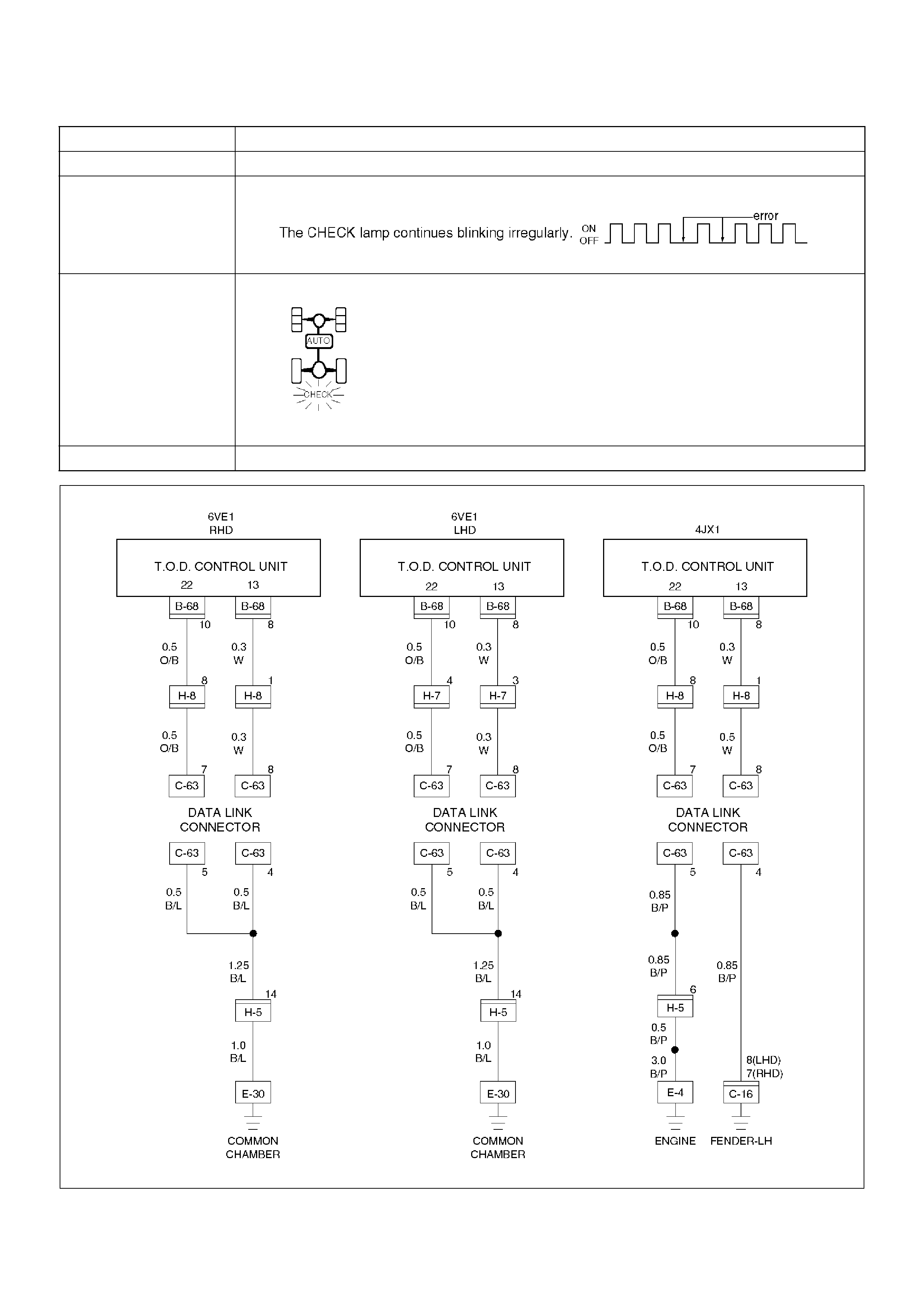
D04RY00072
Chart G The trouble codes are displayed.
Function of circuit —
Fail condition
Indicator lamp status
Transfer position —

Step Action Yes No
1 Disconnect the ECU connector from ECU.
Is the continuity established between terminals (B–68)8 and (B–
67)11?
Go to Step 2
The ECU has
failed. Replace
the ECU.
Go to Step 3
2 Is the self-diagnostic connector short-circuited?
Go to Step 3
Repair the
self-diagnostic
connector
circuit.
Go to Step 3
3 1. Check that all the parts are mounted.
2. Clear the trouble codes.
Is this step complete?
Repeat
the“Diagnosis
Flow”. Return to Step 3
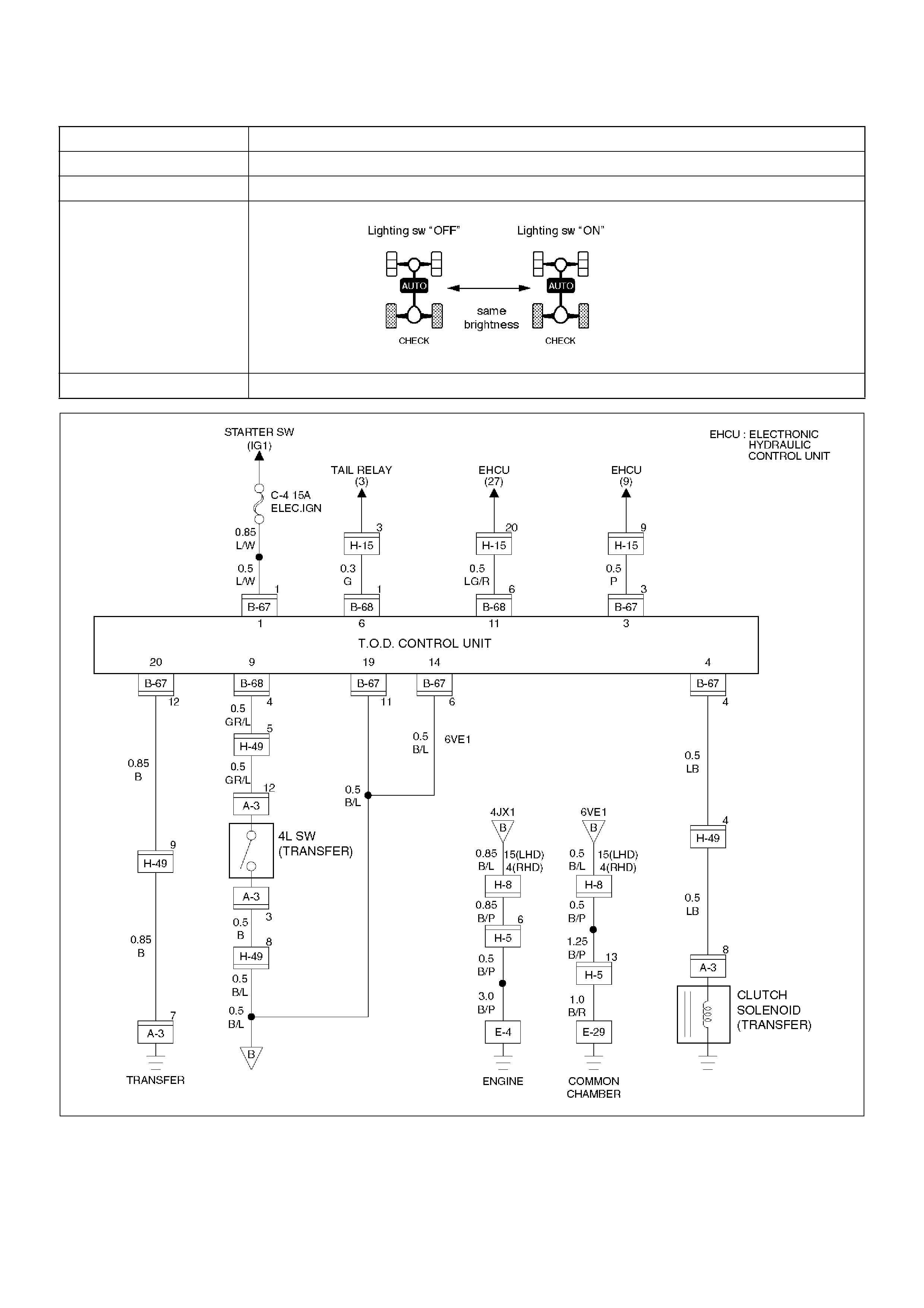
D04RY00073
Chart H lighting switch circuit
Function of circuit Reads in the status of lighting switch and reduces the indicator brightness at night.
Fail condition Even if the lighting switch is pressed on and off, brightness does not change.
Indicator lamp status
Transfer position All position (example TOD mode)

Step Action Yes No
1 1. Disconnect ECU connector.
2. Turn on the starter switch.
Is battery voltage observed between ECU terminals (B–68)1 and
(B–67)11?
Go to Step 2
Wirers are
broken lighting
SW circuit.
Repair the
circuit.
Go to Step 4
2 Turn lighting SW“ON”.
Is 0 V observed between ECU terminal (B–68)1 and (B–67)11?
Go to Step 3
Lighting SW
circuit battery
short. Repair
the circuit.
Go to Step 4
3 Connect ECU terminal.
While the lighting switch is pressed on and off, does the
brightness of the indicator change?
The fault is not
reproduced.
Refer to
“intermittent
Failures”
The ECU has
failed. Replace
the ECU.
Go to Step 4
4 Check that all the parts are mounted.
Is this step complete?
Repeat
the“Diagnosis
Flow”. Return to Step 4

Diagnosis from Symptom
Troubles that are not indicated by the warning lamp are
listed in the table below. These troubles are caused by
the faults that cannot be detected by the self-diagnostic
function of the control unit.
If this type of trouble is observed, interview the
customer and conduct test runs to reproduce the
trouble, cross-check the reported trouble with the listed
phenomena, and diagnose and analyze the trouble on
the item by item basis.
Phenomena Major cause Corrective action
1 The tight corner braking is observed
when the vehicle is subject to full
steering.
• The standard Tyres are not used.
• The tire pressure is incorrect.
• The Tyres are worn inuniformity.
• The transfer or wiring is imperfect.
• The limited slip differential is
failed.
Check and recondition the
vehicle according to Chart 1.
2 Even if the 4WD AUTO SW is select
to the 4WD position, the 4WD mode
is not active, resulting in remarkable
rear wheel spin.
• The transfer or wiring is imperfect.
• The shift on the fly system is
failed.
Check and recondition the
vehicle according to Chart 2.
3 • When the 4WD AUTO SW is
selected to the 4WD position, the
drive resistance of the 4WD
system is too large to get
sufficient running speed.
• Noised drive line.
• The standard Tyres are not used.
• The tire pressure is incorrect.
• The Tyres are worn inuniformity.
• The transfer or wiring is imperfect.
• The limited slip differential is
failed.
Check and recondition the
vehicle according to Chart 1.
4 The shift on the fly system (front
axle) generates gear noises.
• The wiring is imperfect.
• The shift on the fly system is
failed.
Check and recondition the
vehicle according to Chart 3.
5 The braking distance gets long even
when the ABS is active.
• The wiring is imperfect.
• The ABS is failed.
Check and recondition the
vehicle according to Chart 4.

D04RY00073
Chart 1 The tight corner braking is observed.
Function of circuit —
Fail condition When the vehicle is subject to full steering in the TOD mode, the drive resistance gets
large or the judder occurs. Otherwise, the above fault is observed only when the brake is
applied.

Step Action Yes No
1 Are the front and rear Tyres in specified size?
Go to Step 2
Replace the
Tyres with
specified ones,
and service the
new Tyres.
Go to Step 16
2 Is the tire pressure correct?
Go to Step 3
Inflate tyres to
recommended
pressure.
Go to Step 16
3 Are the Tyres free from abnormal wear?
Go to Step 4
Replace the
Tyres with
specified ones,
and service the
new Tyres.
Go to Step 16
4 Are different types of Tyres used?
Go to Step 5
Replace the
Tyres with
specified ones,
and service the
new Tyres.
Go to Step 16
5 1. Start the engine.
2. Shift the transfer lever to the high position and switch the
4WD AUTO SW to 4WD position.
3. Fully turn the steering to the left (or right) end, and select the
D range and start the creep run.
Does the tight corner braking occur? Is the judder with chug-chug
sound observed? *Use caution on the operation. Go to Step 6 Go to Step 11
6 1. Shift the transfer lever to the high position and switch the
4WD AUTO SW to the 2H position.
2. Fully turn the steering to the left (or right) end, and select the
D range and start the creep run.
Does the tight corner braking occur? Is the judder with chug-chug
sound observed? *Use caution on the operation. Go to Step 7 Go to Step 14
7 Is an LSD mounted to the rear differential? Go to Step 8 Go to Step 9
8 Is the genuine LSD oil used in the rear differential?
Go to Step 9
Replace the
differential oil.
Go to Step 16
9 Does the engine output the power correctly?
Go to Step 10
Check the
engine.
Go to Step 16
10 Do the speed sensors work correctly? (Check trouble codes.) The ECU has
failed. Replace
the ECU.
Go to Step 16
Replace the
speed sensors.
Go to Step 16
11 Is the tight corner braking observed only when the brake is
applied?
Go to Step 12
Conduct full
steering under
WOT.
Go to Step 5

*NOTE: Before checking this item, run the vehicle more
than 10 meters with the steering wheel in straight
position so that the 4L mechanical lock sleeve can be
released certainly.
12 1. Turn on the starter switch.
Is the battery voltage observed between terminals 11 and 19?
Go to Step 13
Repair the
circuit of
terminal 11
(ABS IN).
Go to Step 16
13 1. Apply the brake and fully turn the steering to the left (or right)
end, and start the creep run.
Does the voltage between terminals 4 and 20 range between 0.1
and 1.0V?
Repair the
transfer
assembly.
Go to Step 16
The ECU has
failed. Replace
the ECU.
Go to Step 16
14 1. Shift the transfer lever to the high position and switch the
4WD AUTO SW to 4WD position.
2. Fully turn the steering to the left (or right) end, and select the
D range and start the creep run.
Does the voltage between terminals 4 and 20 range between 0.1
and 1.0V? Go to Step 15 Go to Step 10
15 1. Select the 4WD AUTO SW to the 2WD position.
2. Jack up the right front wheel.
Does the front tire rotate smoothly?
The fault is not
reproduced.
Refer to
“intermittent
Failures” Go to
Step 16
Repair the
transfer
assembly.
Go to Step 16
16 Check that all the parts are mounted.
Is this step complete?
Repeat
the“Diagnosis
Flow”. Return to Step 16
Step Action Yes No

D04RY00073
Chart 2 The 4WD mode is not active.
Function of circuit —
Fail condition The rear wheels spin in the TOD mode, so the driving torque is not transmitted to the front
wheels. The indicator lamps will not show the 4L and TOD status.

Step Action Yes No
1 Is the trouble code 31 or 26 recorded? Examine the
trouble based
on“Diagnosis
from Trouble
Codes”. Go to Step 2
2 Is any of the trouble codes 28(P1760), 32(P1761) and 33(1762)
recorded?
Examine the
trouble based
on“Diagnosis from
Trouble Codes”. Go to Step 3
3 When the transfer lever is in the specified position, do the TOD
indicator lamps show the correct status?
Go to Step 4
Examine the
trouble based
on“Trouble
Diagnosis
Depending on
The Status of
TOD Indicator”.
4 Shift the transfer lever to the 4L position, fully turn the steering to
the left (or right) end, and start the creep run. Does the tight
corner braking occur?
Go to Step 5
Repair the
transfer
assembly.
Go to Step 7
5 1. Shift the transfer lever to the high (TOD) position.
2. Turn on the starter switch.
Does the voltage between terminals 4 and 20 indicate at least 3V
while the throttle is completely open? Go to Step 6
The ECU has
failed. Replace
the ECU.
Go to Step 7
6 Does the voltage between terminals 4 and 20 indicate at least
0.1V while the throttle is completely closed?
The TOD clutch
is worn. Repair
the transfer
assembly.
Go to Step 7
The ECU has
failed. Replace
the ECU.
Go to Step 7
7 Check that all the parts are mounted.
Is this step complete?
Repeat
the“Diagnosis
Flow”. Return to Step 7
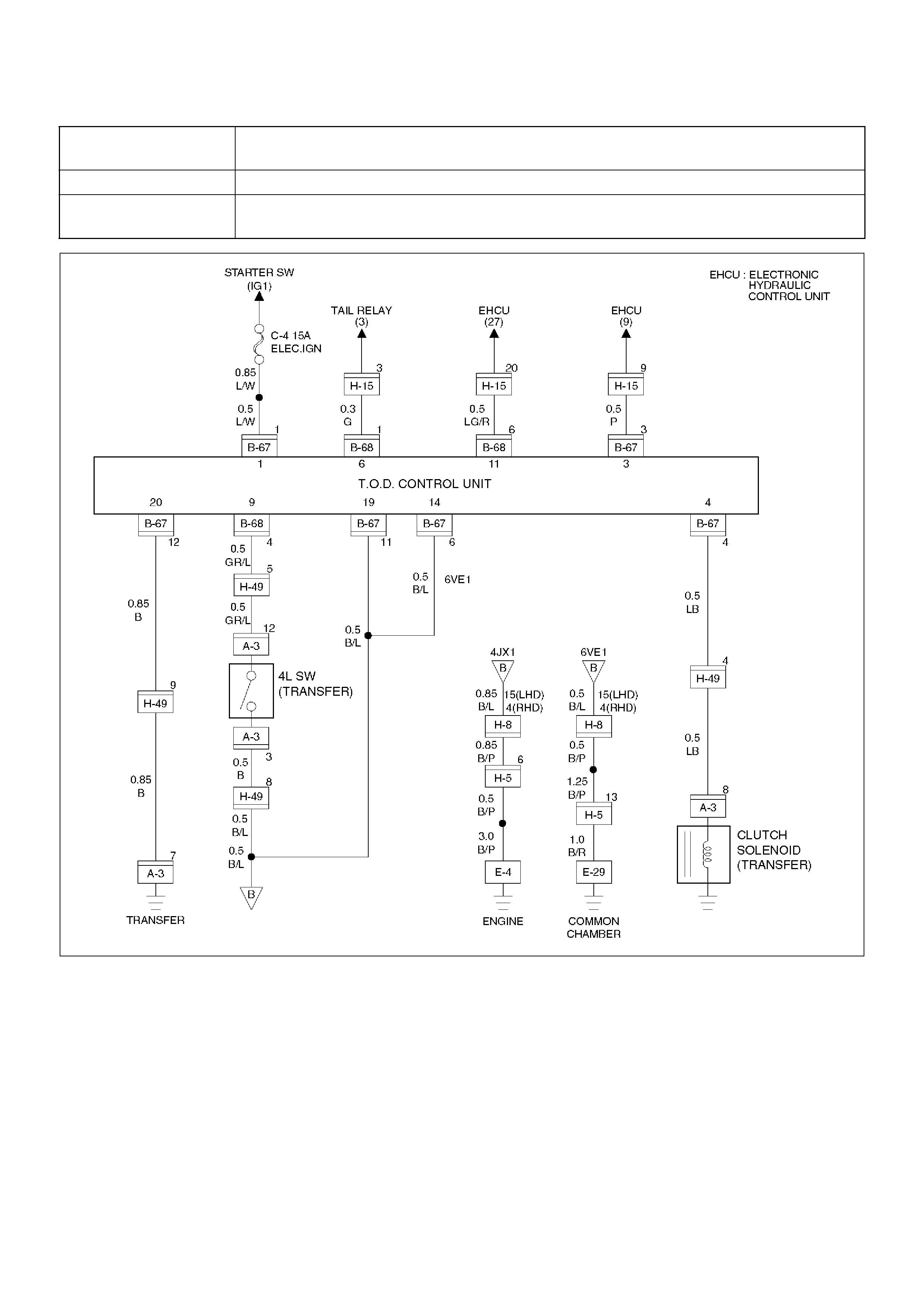
D04RY00073
Chart 3 The shift on the fly system generates gear noises.
(The fuel economy is bad in the 2H mode.)
Function of circuit —
Fail condition When the vehicle is run in the 2H mode, the shift on the fly system generates gear noises
or the front wheel gears are engaged to generate a shock.

Step Action Yes No
1 Do the indicator lamps show the correct status?
Go to Step 2
Examine the
trouble based
on“Touble
Diagnosis
Depending on
The Status of
TOD Indicator”.
2 Is any of the trouble codes 28(P1760), 32(P1761) and 33(P1762)
recorded?
Examine the
trouble based
on“Diagnosis from
Trouble Codes”. Go to Step 3
3 Turn on the starter switch.
Is the battery voltage observed between terminals 1 and 20? Go to Step 4 Go to Step 5
4 When the 4WD AUTO SW is selected to the 2WD position, are
the front axle gears correctly disengaged (and when the left front
tire is jacked up and turned, is the front propeller shaft standstill)?
The fault is not
reproduced.
Refer to
“intermittent
Failures”
The shift on the
fly system is
failed (refer to
Section 4B1)
Go to Step 6
5 Does the battery voltage maintain the correct level?
Repair the
battery circuit.
Go to Step 6
Repair the
battery and
charging
system.
Go to Step 6
6 Check that all the parts are mounted.
Is this step complete?
Repeat
the“Diagnosis
Flow”. Return to Step 6
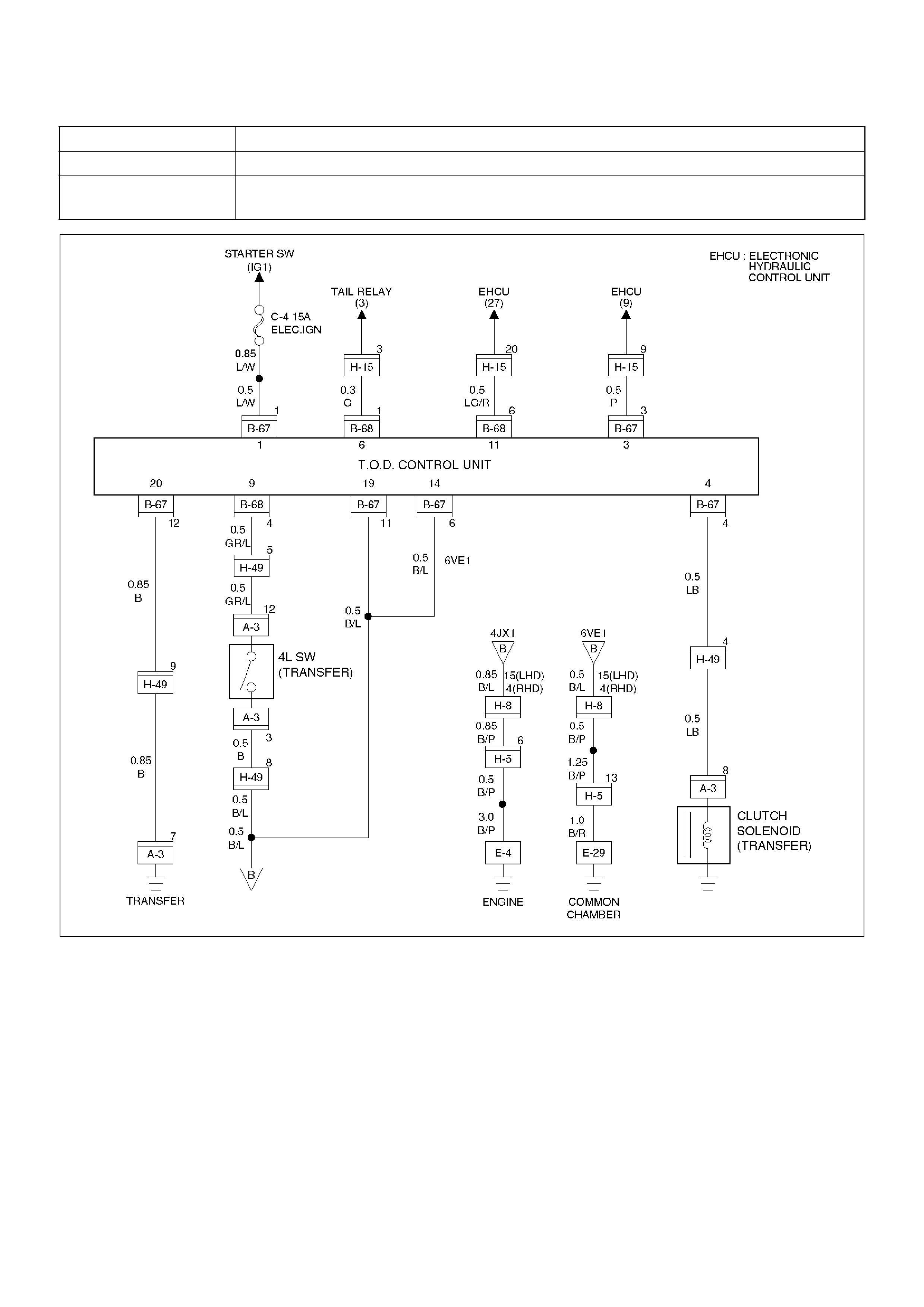
D04RY00073
Chart 4 The braking distance gets long even when the ABS is active.
Function of circuit —
Fail condition Enough deceleration is not obtained and the braking distance gets long even when the
ABS is active in the 2H mode.
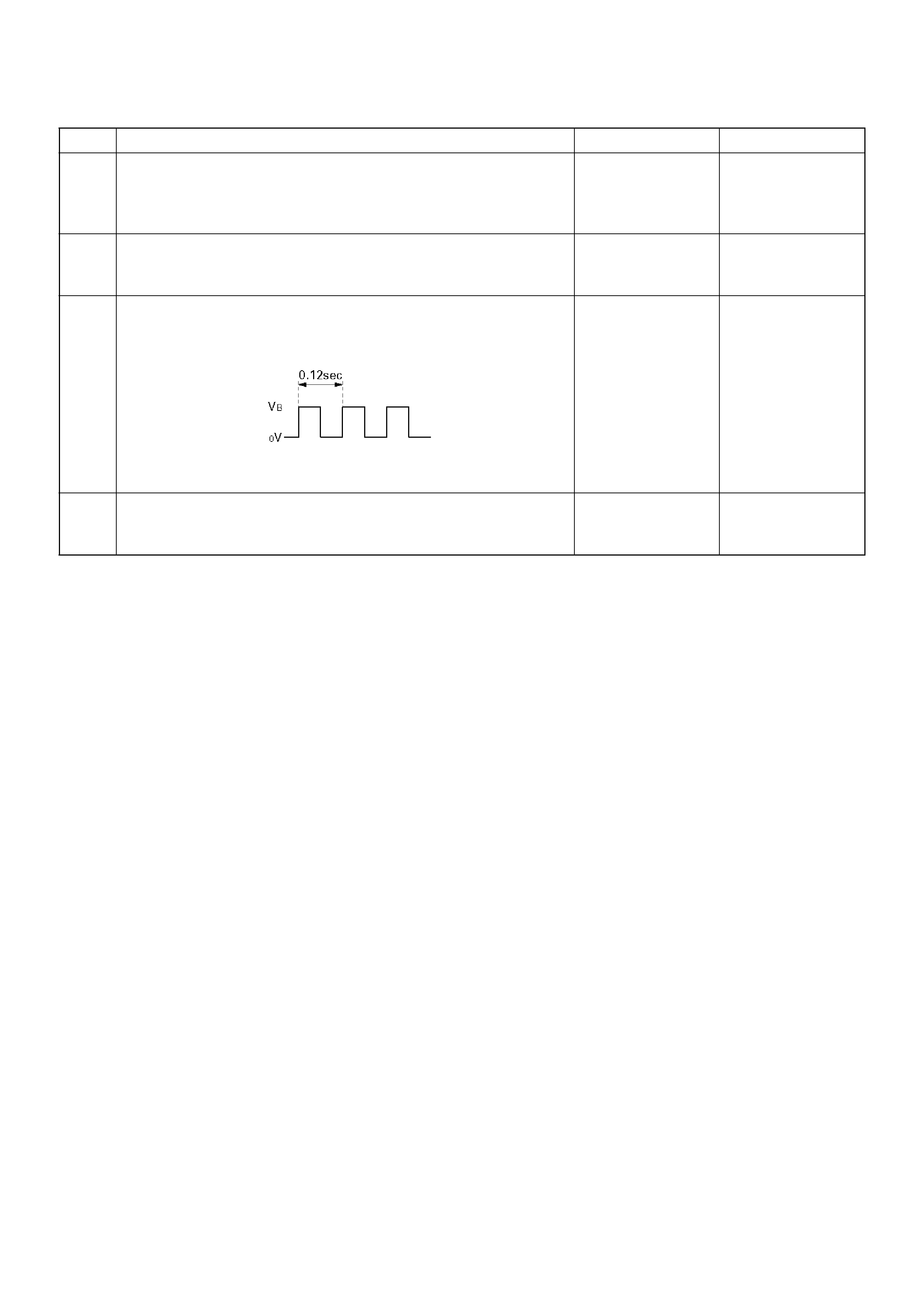
Step Action Yes No
1 Are the brake and ABS systems healthy?
Go to Step 2
Repair the
brake and ABS.
Refer to
section 5A.
2 Turn on the starter switch.
Is the battery voltage observed between terminals 1 and 20?
Go to Step 3
Repair the
battery system.
Go to Step 4
3 1. Select the 4WD AUTO SW to the 2WD position.
2. The voltage between terminals 3 and 19 range between 7.5
and 16V (0.12 seconds make a cycle)
Does the voltage within the range specified? Go to Step 4
The ECU has
failed. Replace
the ECU.
Go to Step 4
4 Check that all the parts are mounted.
Is this step complete?
Repeat
the“Diagnosis
Flow”. Return to Step 4