
SECTION 7F - TRANSFER CASE (STANDARD TYPE)
Service Precaution
General Description
Transfer Rear Oil Seal
Removal
Installation
Transfer Case Assembly
Removal
Installation
Transfer Rear Cover Assembly (4WD Switch Model)
Transfer Rear Cover Assembly and Associated
Parts
Removal
Installation
Disassembly
Inspection and Repair
Reassembly
Transfer Rear Cover Assembly (Except 4WD Switch
Model)
Transfer Rear Cover Assembly and Associated
Parts
Removal
Installation
Disassembly
Inspection and Repair
Reassembly
Detent, Shift Arm, and Interlock Pin
Disassembled View
Disassembly
Inspection and Repair
Reassembly
Transfer Case Assembly
Disassembled View
Disassembly
Reassembly
Main Data and Specifications
Special Tools
Service Precaution
WARNING: THIS VEHICLE HAS A SUPPLEMENTAL
RESTRAINT SYSTEM (SRS). REFER TO THE SRS
COMPONENT AND WIRING LOCATION VIEW IN
ORDER TO DETERMINE WHETHER YOU ARE
PERFORMING SERVICE ON OR NEAR THE SRS
COMPONENTS OR THE SRS WIRING. WHEN YOU
ARE PERFORMING SERVICE ON OR NEAR THE
SRS COMPONENTS OR THE SRS WIRING, REFER
TO THE SRS SERVICE INFORMATION. FAILURE TO
FOLLOW WARNINGS COULD RESULT IN POSSIBLE
AIR BAG DEPLOYMENT, PERSONAL INJURY, OR
OTHERWISE UNNEEDED SRS SYSTEM REPAIRS.
CAUTION: Always use the correct fastener in the
proper location. When you replace a fastener, use
ONLY the exact part number for that application.
HOLDEN will call out those fasteners that require a
replacement after removal. HOLDEN will also call
out the fasteners that require thread lockers or
thread sealant. UNLESS OTHERWISE SPECIFIED,
do not use supplemental coatings (Paints, greases,
or other corrosion inhibitors) on threaded fasteners
or fastener joint interfaces. Generally, such
coatings adversely affect the fastener torque and
the joint clamping force, and may damage the
fastener. When you install fasteners, use the correct
tightening sequence and specifications. Following
these instructions can help you avoid damage to
parts and systems.
General Description
Manual Transmission - With Shift On The Fly and 4WD Switch
A07RW019
Manual Transmission - with Shift On The Fly, without 4WD switch
A07RW054
Manual Transmission - without Shift On The Fly, without 4WD Switch
A07RW053
A/TTransmission - With Shift On The Fly and 4WD SwitchTransmission - With Shift On The Fly and Manual
Automatic Transmission - with Shift On The Fly and 4WD switch
A07RW001

Automatic Transmission - With Shift On The Fly, without 4WD Switch
A07RW056
Automatic Transmission - Without Shift On The Fly, without 4WD Switch
A07RW055
The transfer case is used to provide a means of
providing power flow to the front axle. The transfer case
also provides a means of disconnecting the front axle,
providing better fuel economy and quieter operation
when the vehicle is driven on improved roads where
four wheel drive is not required. In addition, the transfer
case provides an additional gear reduction when
placed in low range, which is useful when difficult off–
road conditions are encountered.
A floor mounted shift lever is used to select the high–
low range. When four wheel drive switch has been
turned on, the four wheel drive indicator light is
designed to come on when the front axle has been
engaged.
Transfer Rear Oil Seal
Removal
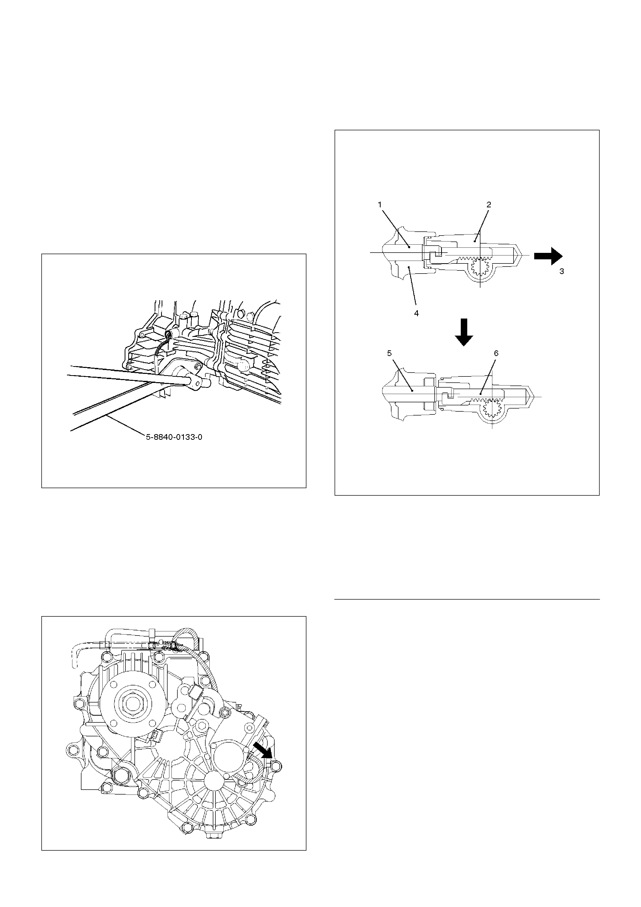
1. Disconnect the rear propeller shaft from the transfer
case side.
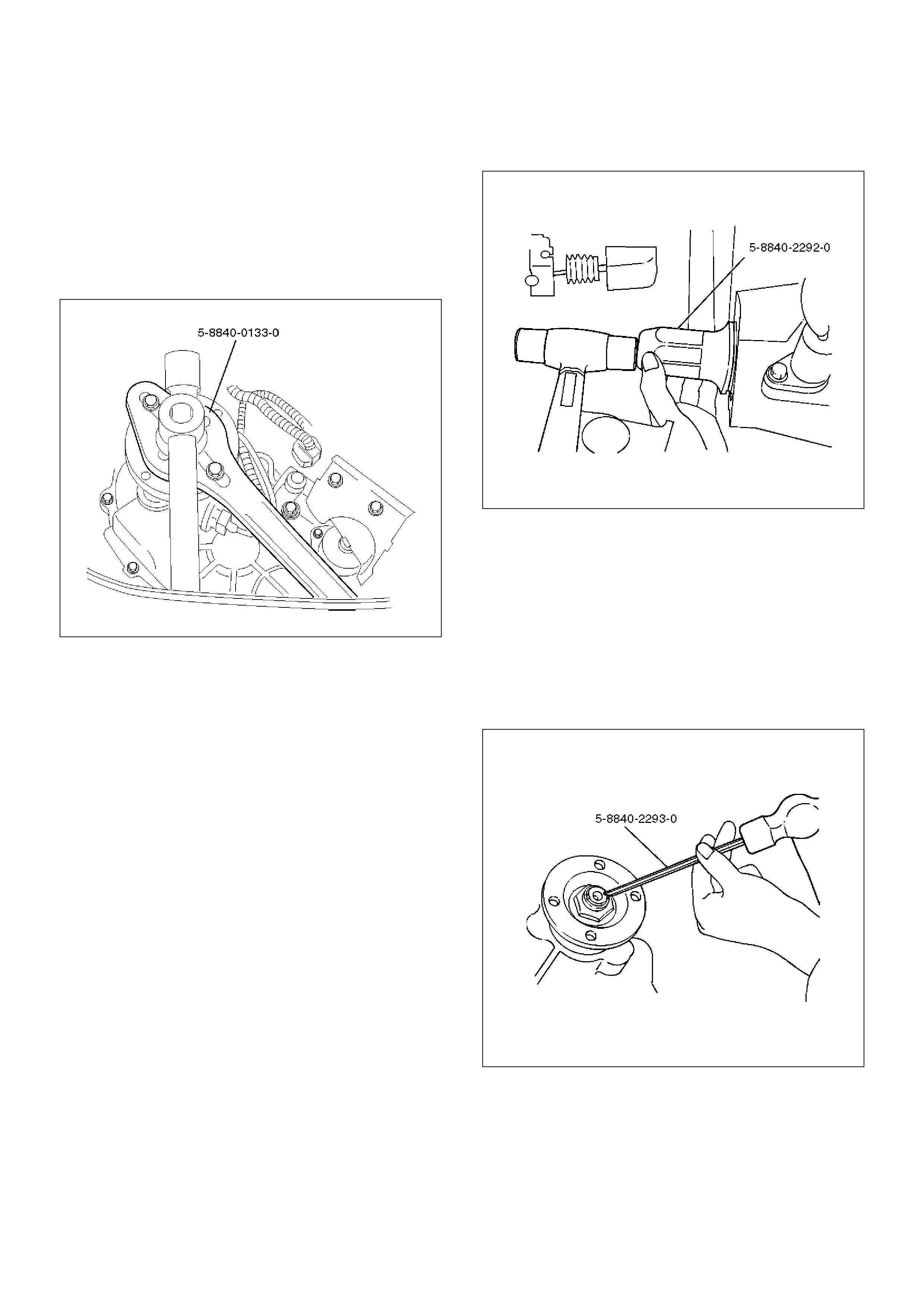
2. Remove end nut and rear companion flange, using
the companion flange holder 5–8840–0133–0 (J–
8614–11).
266RW026
3. Use the universal puller to remove the rear
companion flange and O–ring.
4. Remove the oil seal from the transfer case.
Installation
To install, follow the removal steps in the reverse order,
noting the following points:
1. Install oil seal and apply engine oil to the oil seal
outer surfaces.
2. Apply the recommended grease (BESCO L2) or
equivalent to the oil seal lip.
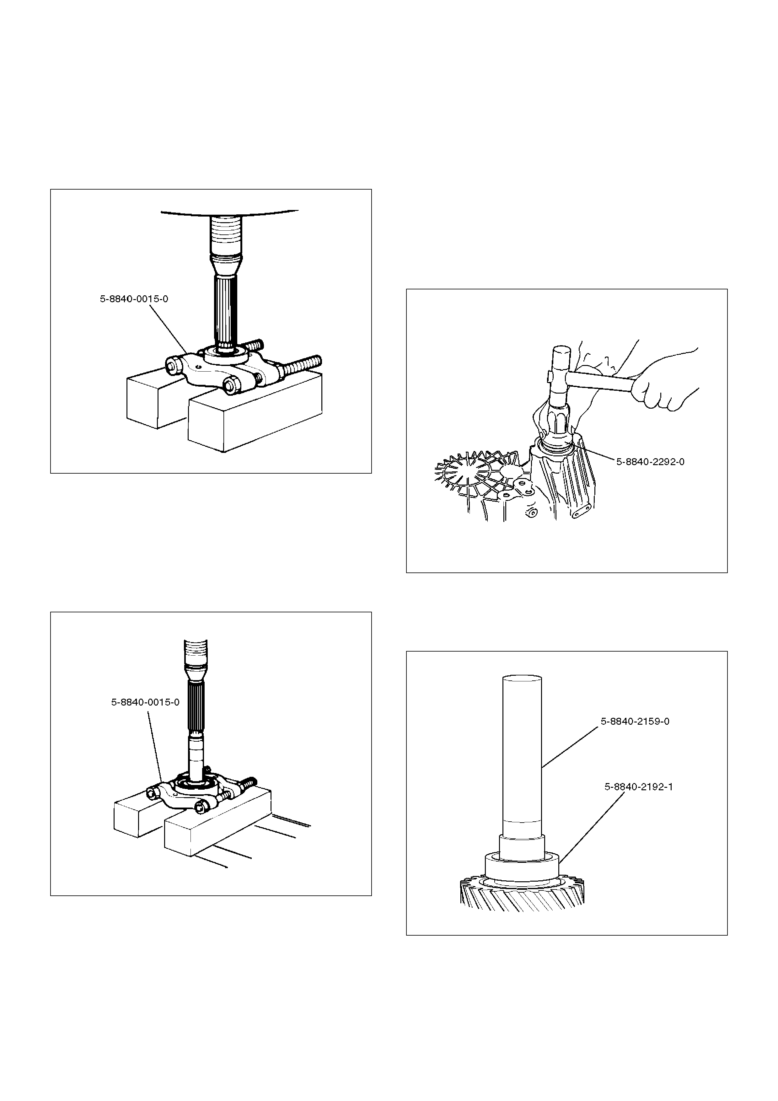
3. Use the oil seal installer 5–8840–2292–0 (J–39208)
to install the rear seal to the transfer rear case.
220RW105
4. Install the rear companion flange and O–ring.
5. Use the companion flange holder 5–8840–0133–0
(J–8614–11) to install a new end nut and tighten to
the specified torque.
Torque: 167 N·m (17.0kg·m/123 lbft)
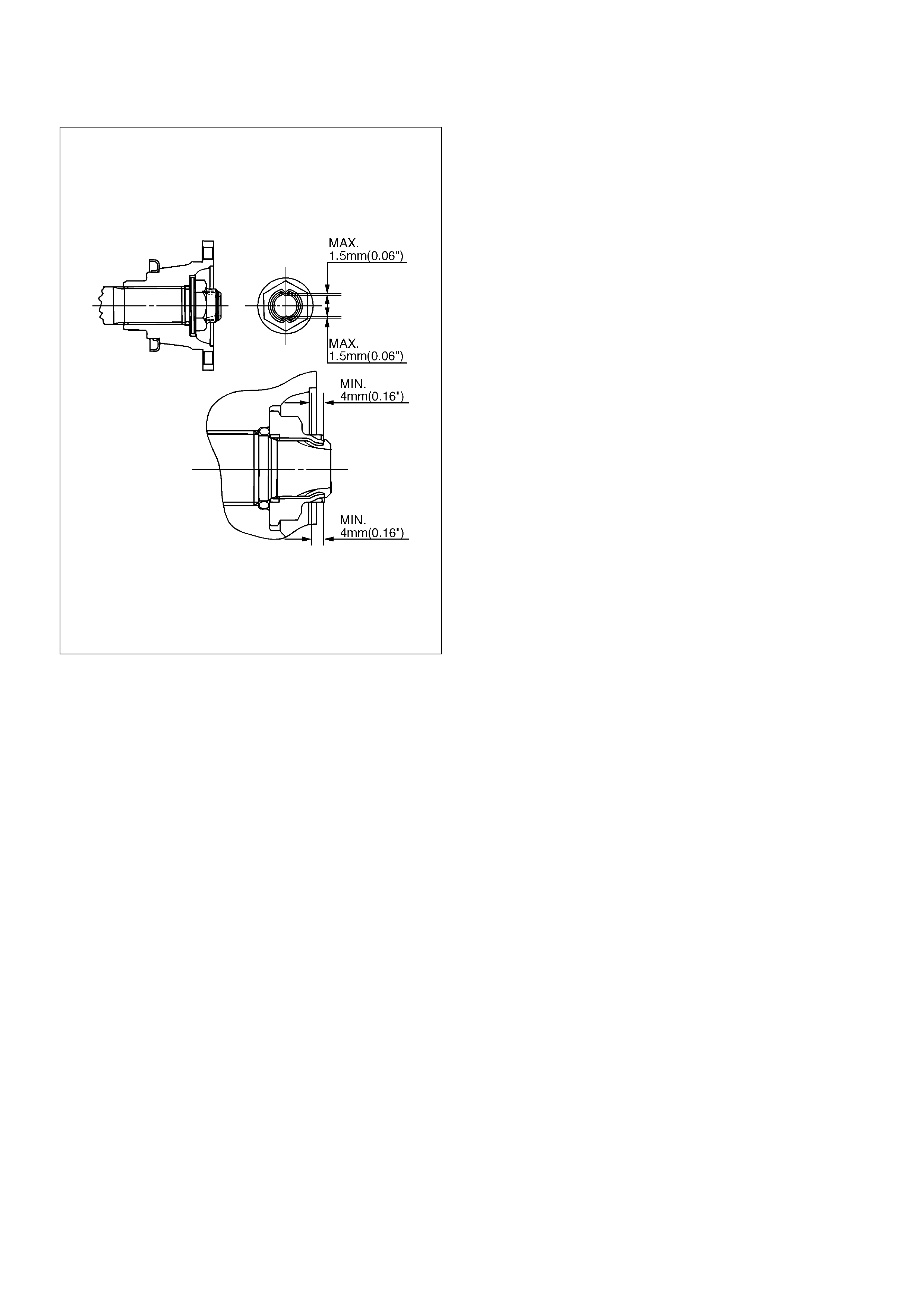
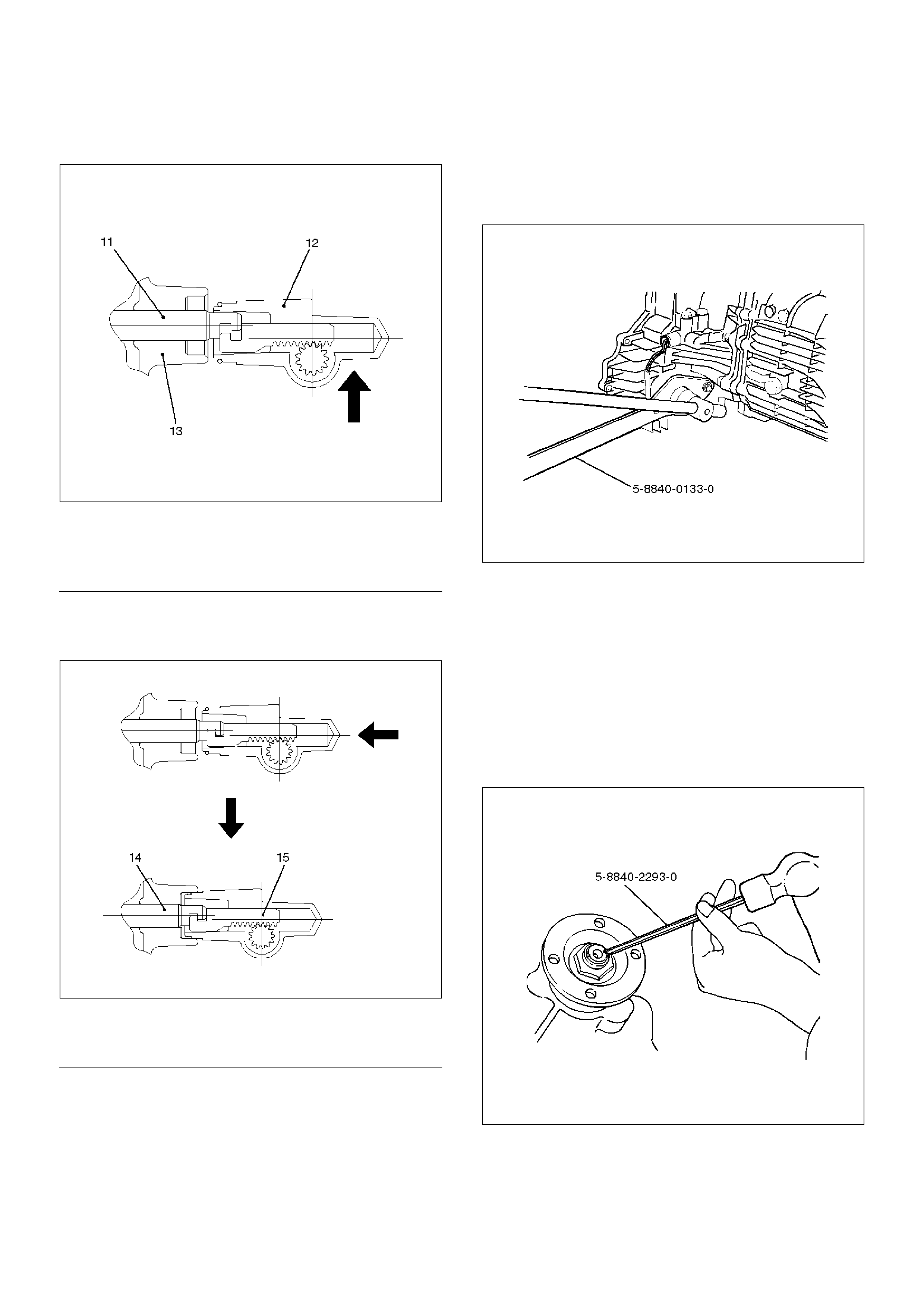
6. Use the punch 5–8840–2293–0 (J–39209) to stake
the end nut at two spots.
NOTE: Be sure to confirm that there is no crack at the
staked portion of the end nut after staking.
266RW027
266RW002
7.Connect the rear propeller shaft to the transfer case
and tighten to the specified torque.
Torque: 63 N·m (6.4kg·m/46 lbft)
Transfer Case Assembly
Removal
NOTE: Before removing the transmission & transfer
assembly from the vehicle, change the transfer mode to
2WD by pushing button switch on dash panel. (4WD
Switch Model)
1.Disconnect the battery ground cable.
2.Drain the transfer case fluid, if overhauling the
transter case assembly.
3.Remove the exhaust and transfer protectors.
4.Remove the rear and front propeller shafts from the
transfer case side.
5.Remove the transfer control lever knob.
6.Disconnect the harness connectors and remove the
front console.
7.Remove the selector lever assembly.
8. Remove the transfer control lever.
9. Disconnect the 4WD switch connector, speed
sensor harness connector and 2WD–4WD actuator
harness connector (4WD Switch Model) from the
transmission harness.
10. Support the transfer case with a transmission jack.
11. Remove the transmission–transfer bolts and the nut
(M/T).
12. Remove the transfer case assembly from the
vehicle.
Installation
To install, follow the removal steps in the reverse order,
noting the following points:
1. Apply a thin coat of molybdenum disulfide grease to
the input shaft spline and install the transter case
assembly to the vehicle.
260RW001
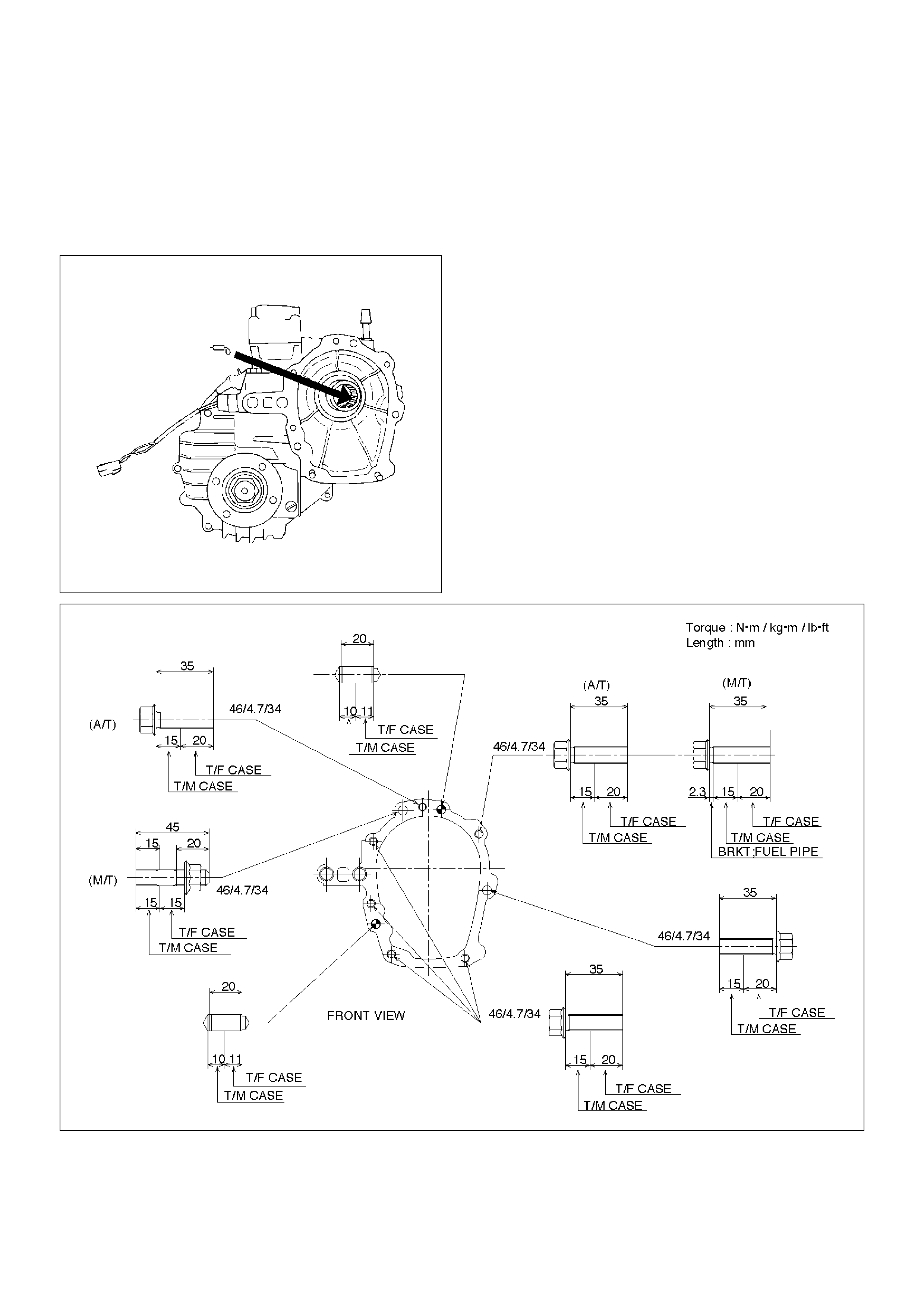
2. Tighten the transmission–transfer bolts and the nut
(M/T) to the specified torque.
Torque: 46 N·m (4.7kg·m/34 lbft)
3. Tighten the propeller shaft bolts to the specified
torque.
Torque: 63 N·m (6.4kg·m/46 lbft)
4. Tighten the transfer protector bolts to the specified
torque.
Torque: 37 N·m (3.8kg·m/27 lbft)
256RW030
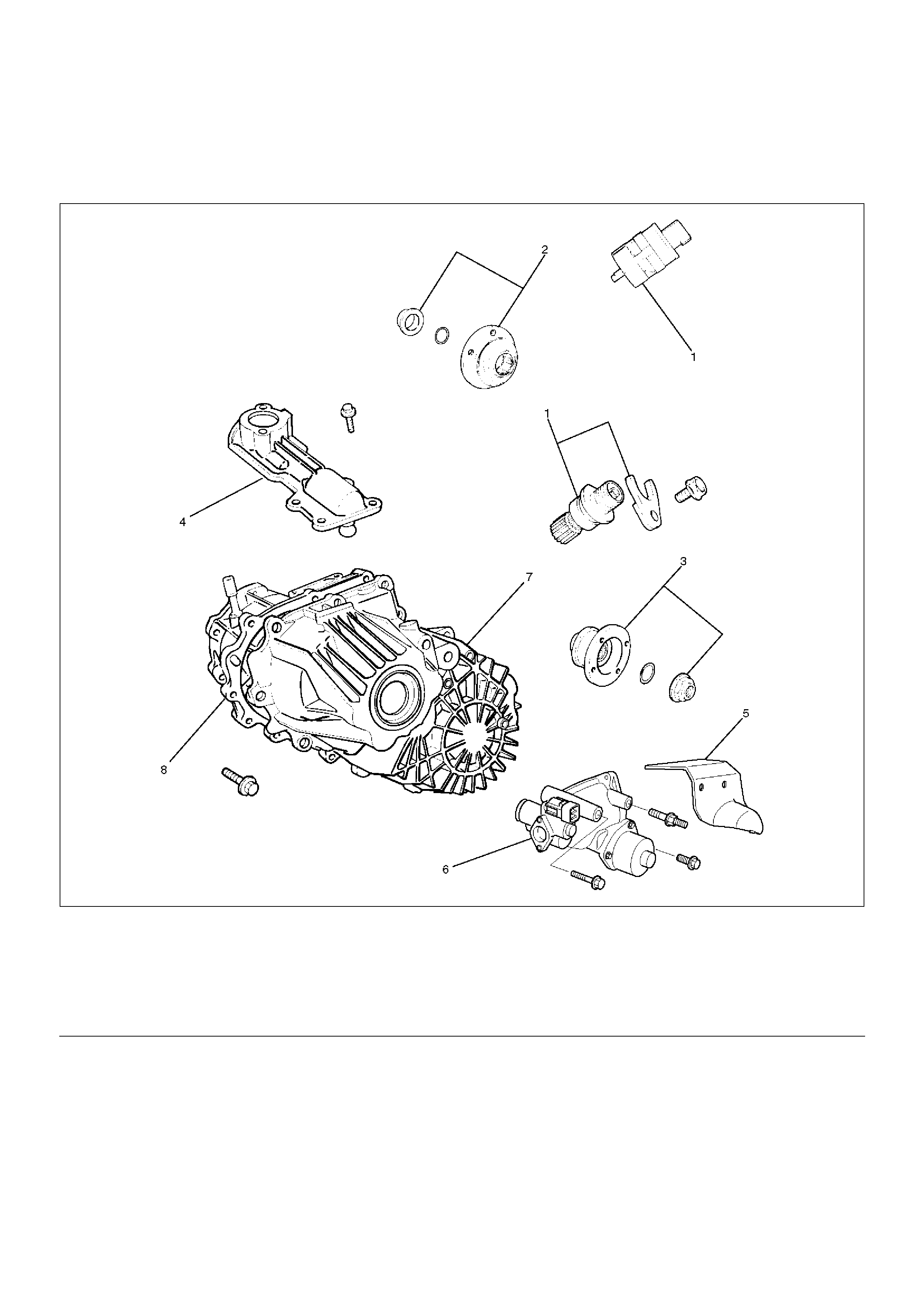
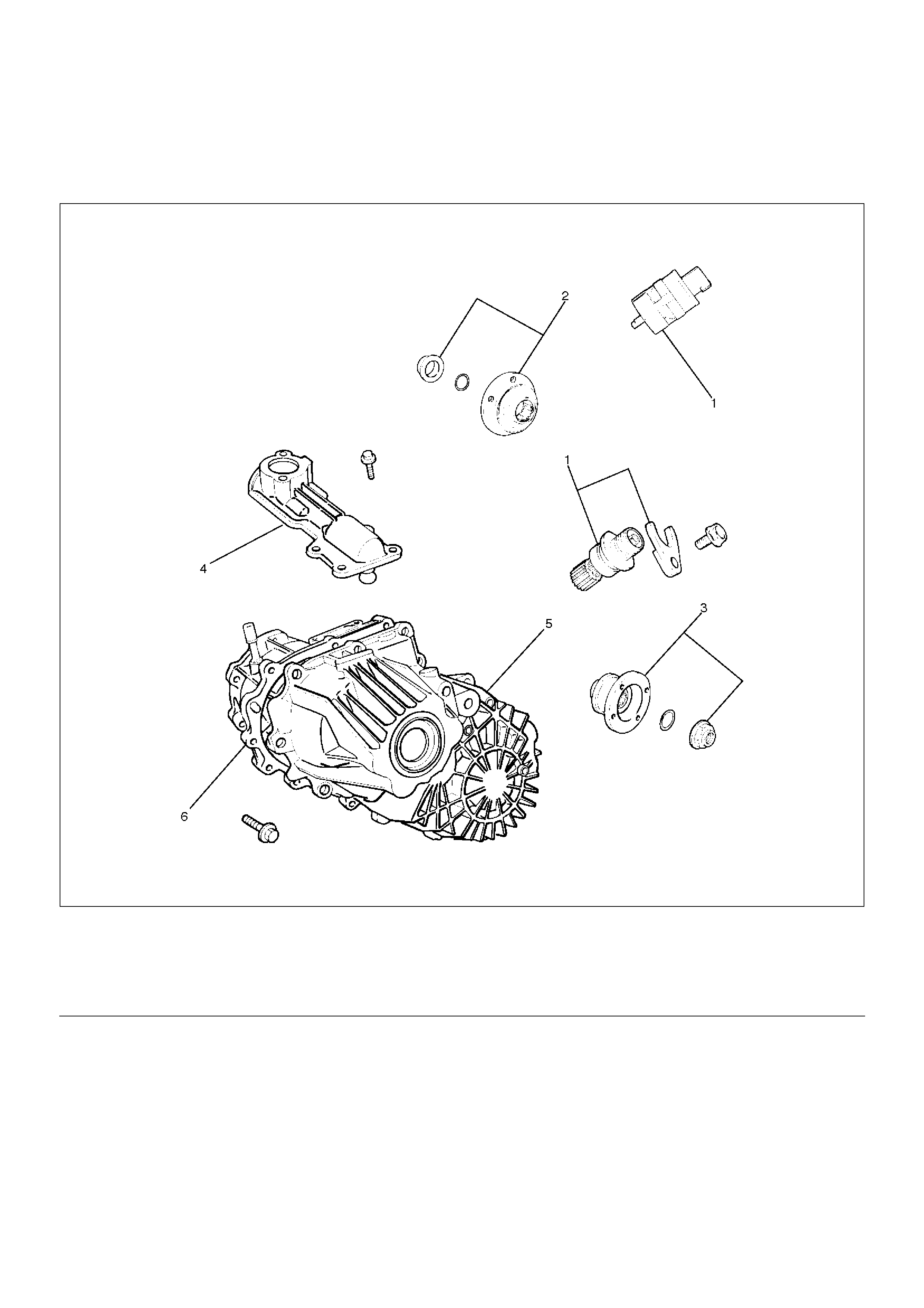
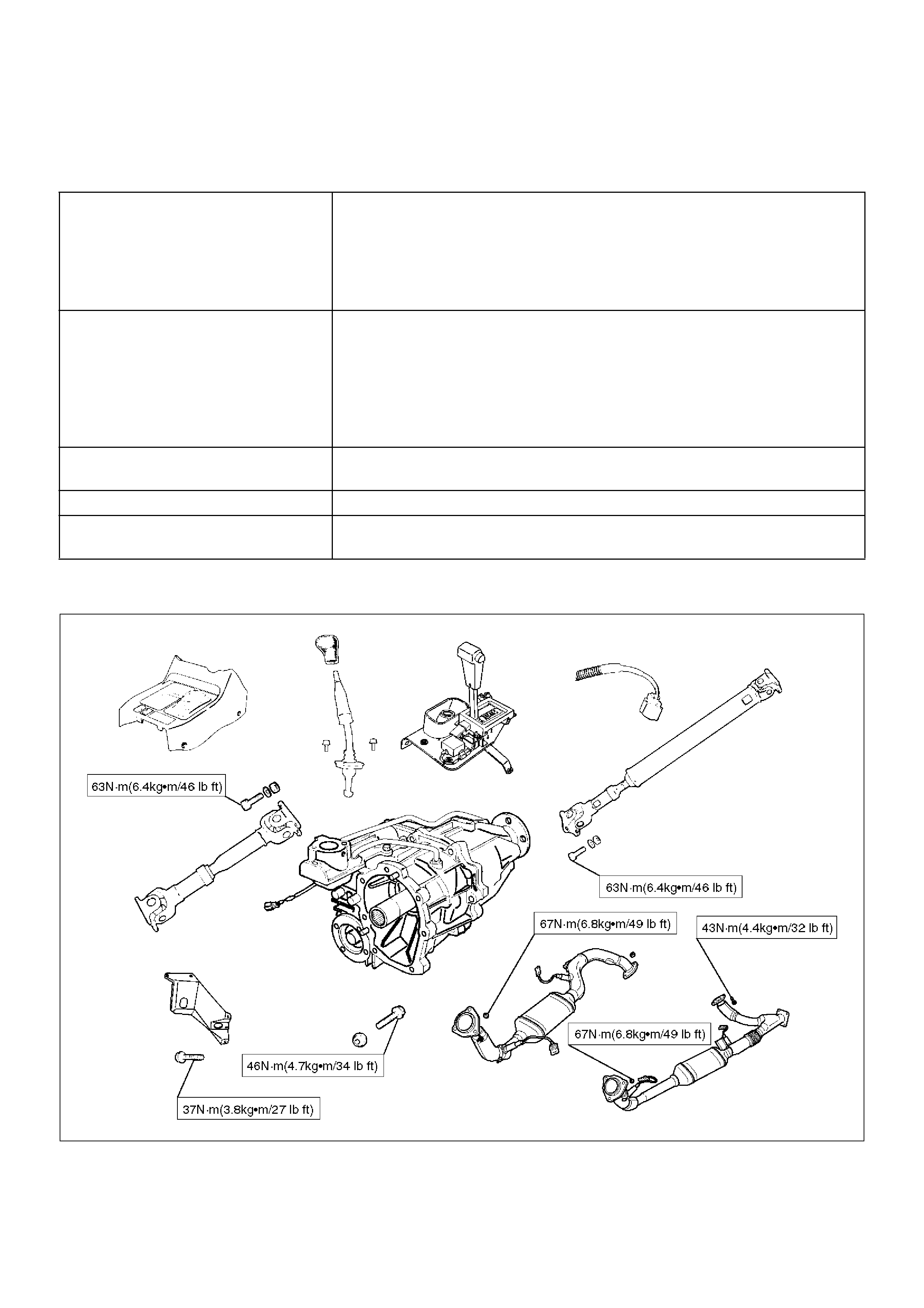
Transfer Rear Cover Assembly (4WD Switch Model)
Transfer Rear Cover Assembly and Associated Parts
220RW102
EndOFCallout
Legend
(1) Speedometer Sensor, Speedometer Driven
Gear and Plate
(2) Front Companion Flange
(3) Rear Companion Flange
(4) Control Box Assembly
(5) 2WD–4WD Actuator Heat Protector
(6) 2WD–4WD Actuator Assembly
(7) Transfer Rear Cover Assembly
(8) Transfer Case Assembly
Removal
1. Remove the speedometer sensor.
2. Remove the plate.
3. Remove the speedometer driven gear bushing and
driven gear.
NOTE: Apply a reference mark to the driven gear
bushing before removal.
4. Remove the front companion flange and the rear
companion flange, using the flange companion
holder 5–8840–0133–0 (J–8614–11) to remove the
end nuts.
262RW067
NOTE: Use a universal puller to remove the rear
companion flange.
5. Disconnect the actuator breather hose and the
transfer breather hose from the control box.
6. Remove the control box assembly.
7. Disconnect the actuator breather hose and remove
the 2WD–4WD actuator heat protector from the
2WD–4WD actuator assembly.
220RW085
8. Remove the 2WD–4WD actuator assembly bolts.
9. Pull the 2WD–4WD actuator assembly with 2WD–
4WD shift rod.
220RW027
EndOFCallout
Legend
(1) Shift Rod: 2WD–4WD (Position: 2WD)
(2) 2WD–4WD Actuator Assembly
(3) Pull Cover
(4) Rear Cover Assembly
(5) Position: 4WD
(6) Mode: 2WD
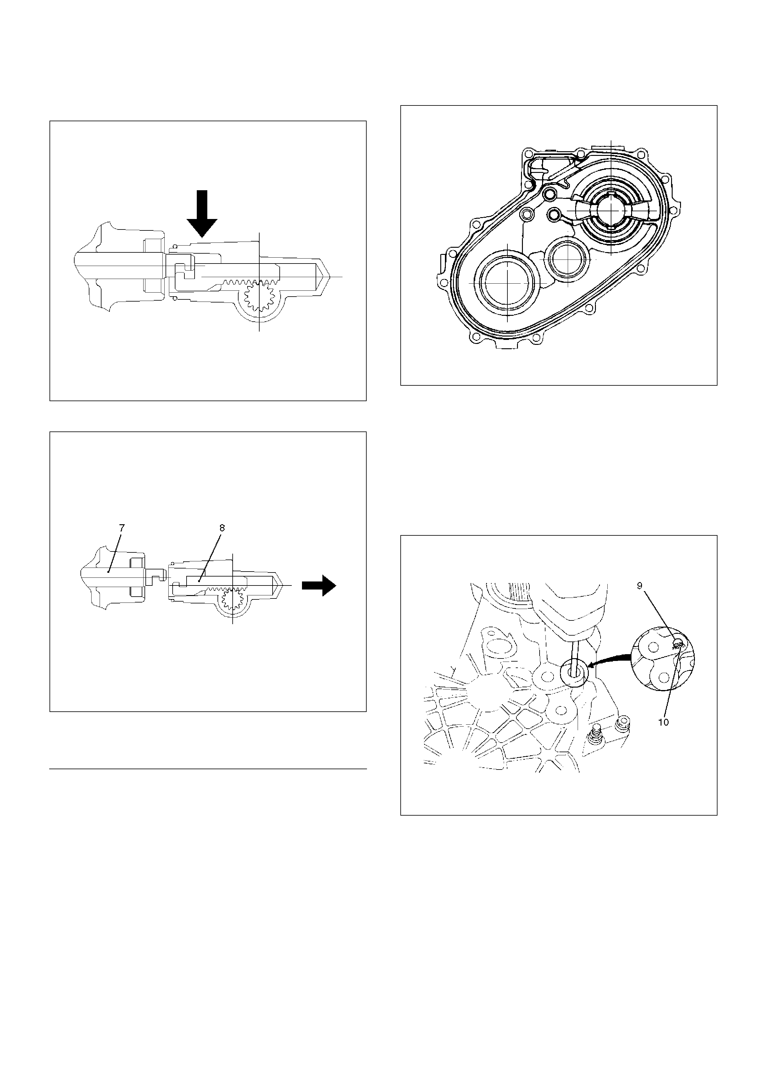
10. Offset the actuator assembly.
220RW028
11. Remove the actuator assembly.
220RW029
EndOFCallout
12. Remove the transfer rear cover assembly from the
transfer case assembly.
Installation
1. Apply the recommended liquid gasket (LOCTITE
17430) or its equivalent to the transfer rear cover
fitting faces.
220RS017
2. Install the transfer rear cover assembly to the
transfer case assembly.
3. Perform the following steps before fitting the transfer
rear case:
1. Shift the high–low shift rod to the 4H side.
2. The cut–away portion of the select rod head (9)
should align with that of the rear case hole's
stopper (10).
230RW004
4. Tighten the transfer rear case bolts to the specified
torque.
Torque: 37 N·m (3.8kg·m/27 lbft)
5. Shift the 2WD–4WD shift rod (11) to the 4WD side.
Legend
(7) Position: 4WD
(8) Mode: 2WD
6. Join the rod grooves of 2WD–4WD actuator
assembly (12) and shift rod (11).
220RW030
EndOFCallout
7. Push the 2WD–4WD actuator assembly (12) with
2WD–4WD shift rod (11) till the shift rod (11)
reaches the 2WD position.
220RW031
EndOFCallout
8. Tighten the 2WD–4WD actuator bolts to the
specified torque.
Torque: 19 N·m (1.9kg·m/14 lbft)
9. Install the actuator heat protector.
10. Connect the actuator breather hose to the actuator.
11. Install the control box assembly.
Torque: 19 N·m (1.9kg·m/14 lbft)
12. Connect the breather hoses to the control box.
13. Install the rear companion flange and front
companion flange, using the companion flange
holder 5–8840–0133–0 (J–8614–11) to tighten the
flange nuts to the transfer case.
262RW067
14. Tighten the new transfer flange nuts to the specified
torque.
Torque
Rear companion flange: 167 N·m (17.0kg·m/123
lbft)
Front companion flange: 137 N·m (14.0kg·m/101
lbft)
15. Use the punch 5–8840–2293–0 (J–39209) to stake
the rear companion flange nut at two spots.
266RW027
Legend
(11) Shift Rod: 2WD–4WD (Position: 4WD)
(12) 2WD–4WD Actuator Assembly (Mode: 2WD)
(13) Rear Cover Assembly
Legend
(14) Position: 2WD
(15) Mode: 2WD
266RW002
16. Stake the front companion flange nut at one spot.
NOTE: Be sure to confirm that there is no crack at the
staked portion of the flange nut after staking.
17. Install the O–ring (8) to the speedometer driven
gear bushing (7).
18. Install the driven gear to the speedometer driven
gear bushing (7).
19. Install the speedometer driven gear assembly to the
transfer rear cover.
20. Install the plate (6) to the transfer rear case and
tighten to the specified torque.
Torque: 15 N·m (1.5kg·m/11 lbft)
21. Install the speedometer sensor and tighten to the
specified torque.
Torque: 27 N·m (2.8kg·m/20 lbft)
225RW014
Disassembly
226RW154
EndOFCallout
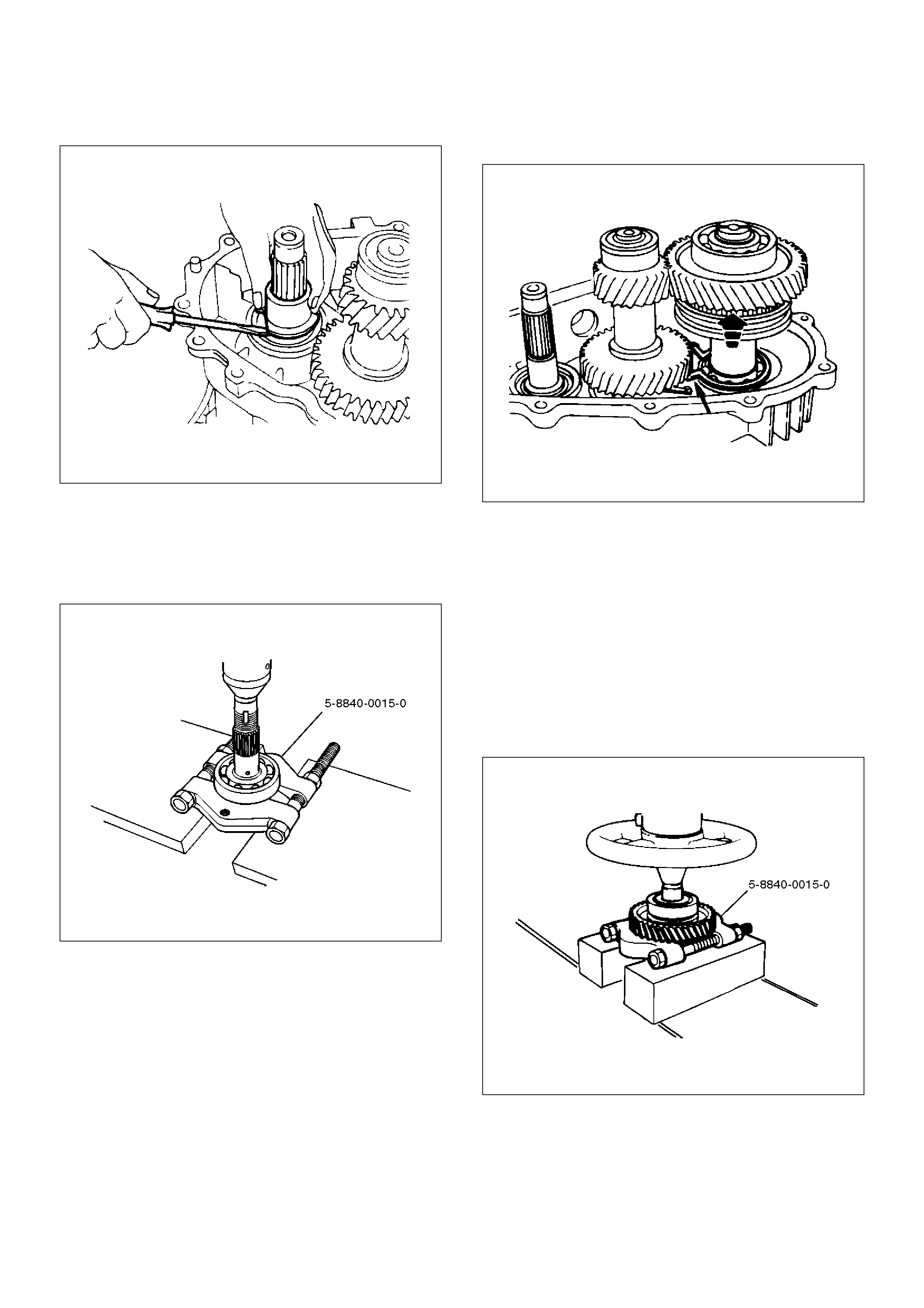
1. Remove the bearing snap ring (3), using a pair of
snap ring pliers.
226RS060
Legend
(1) Rear Output Shaft Assembly
(2) Rear Output Shaft
(3) Bearing Snap Ring
(4) Ball Bearing
(5) Bearing Snap Ring
(6) Ball
(7) Speedometer Drive Gear
(8) Ball Bearing
(9) Transfer Rear Cover (with oil seal)
2.Remove the rear output shaft assembly (1) from the
transfer rear cover (with oil seal).
3.Remove ball bearing (8), using a bench press and
the bearing remover 5–8840–0015–0 (J–22912–
01) .
226RW186
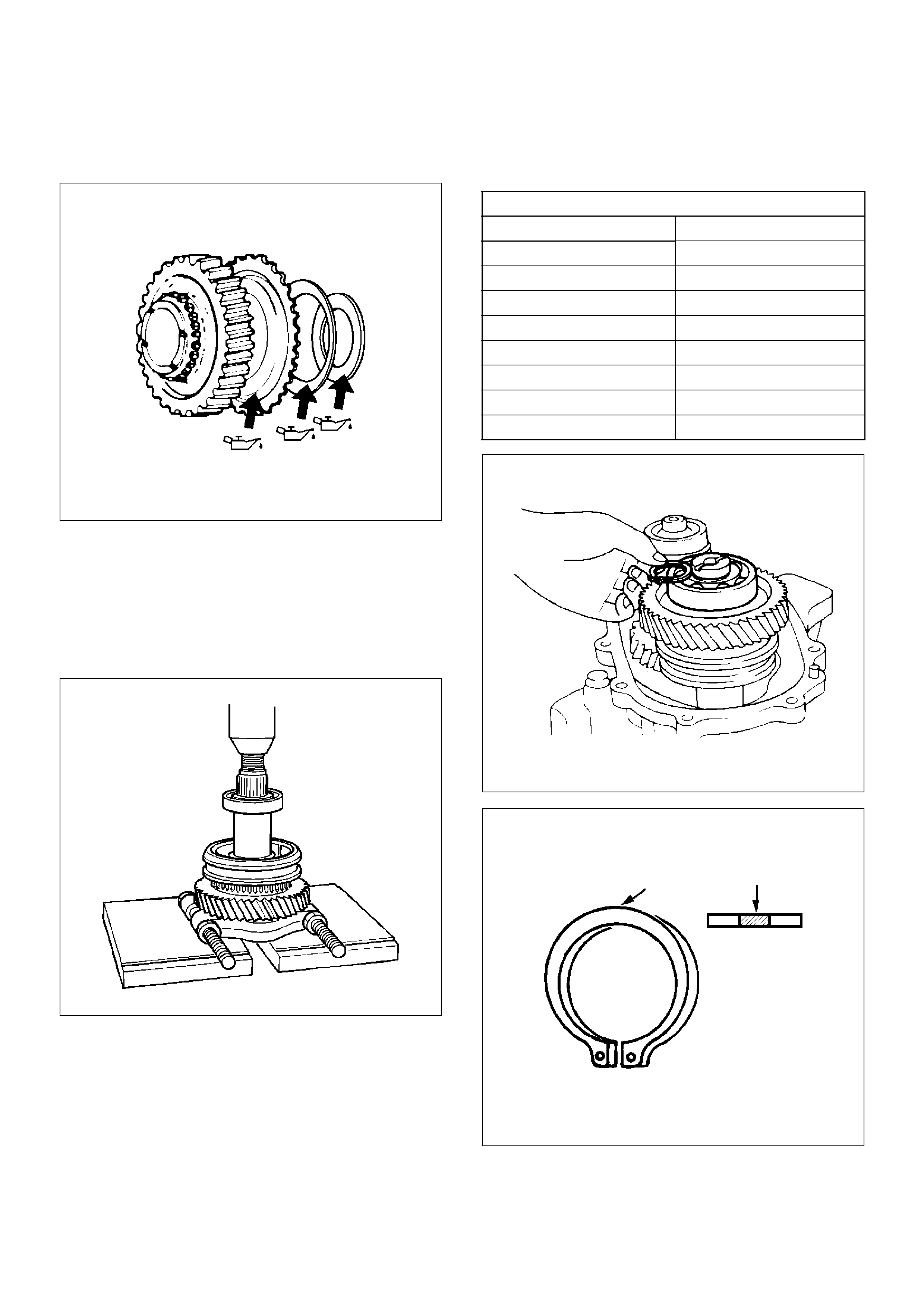
4.Remove the speedometer drive gear (7).
5.Remove the ball (6).
6.Remove the bearing snap ring (5), using a pair of
snap ring pliers.
7.Remove the ball bearing (4) from the rear output
shaft, using a bench press and the bearing remover
5–8840–0015–0 (J–22912–01).
226RW187
Inspection and Repair
Refer to “TRANSFER CASE ASSEMBLY” in this section
for inspection and repair.
Reassembly
1. Install transfer rear cover (with oil seal).
Oil seal replacement
• Remove the oil seal from the transfer rear cover.
• Apply engine oil to the oil seal outer surfaces.
• Fill in recommended grease (BESCO L2) or
equivalent in the oil seal lip.
• Use the oil seal installer 5–8840–2292–0 (J–
39208) to install the rear oil seal to the transfer
rear cover.
220RW104
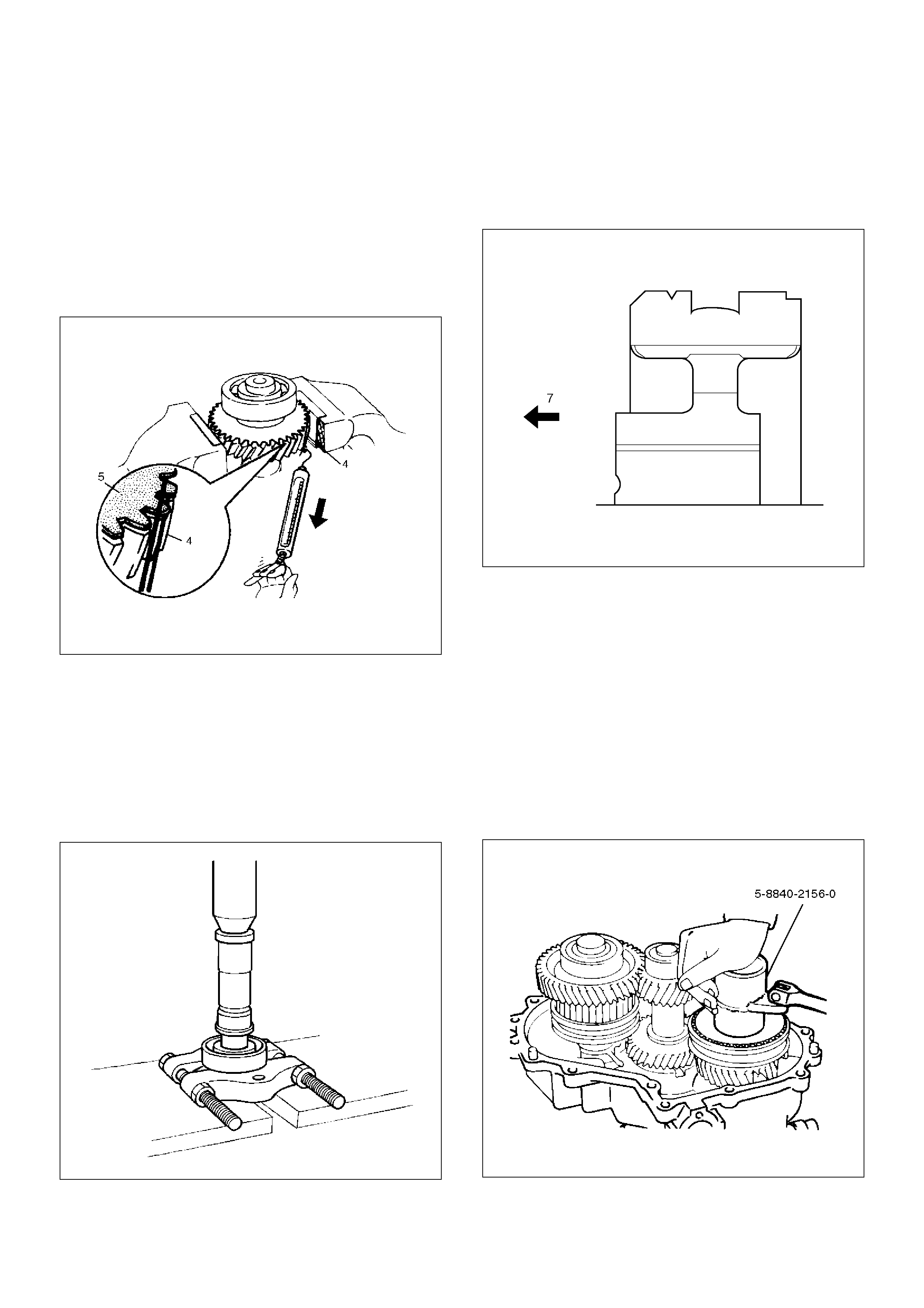
2. Set the snap ring (3), and install ball bearing (4) to
the rear output shaft (2), using the ball bearing
installer 5–8840–2159–0 (J–37223) and the adapter
5–8840–2192–1 (J–37486–A).
262RW068
3. Install the bearing snap ring (5).
4. Install the ball (6).
5. Install the speedometer drive gear (7).
226RS064
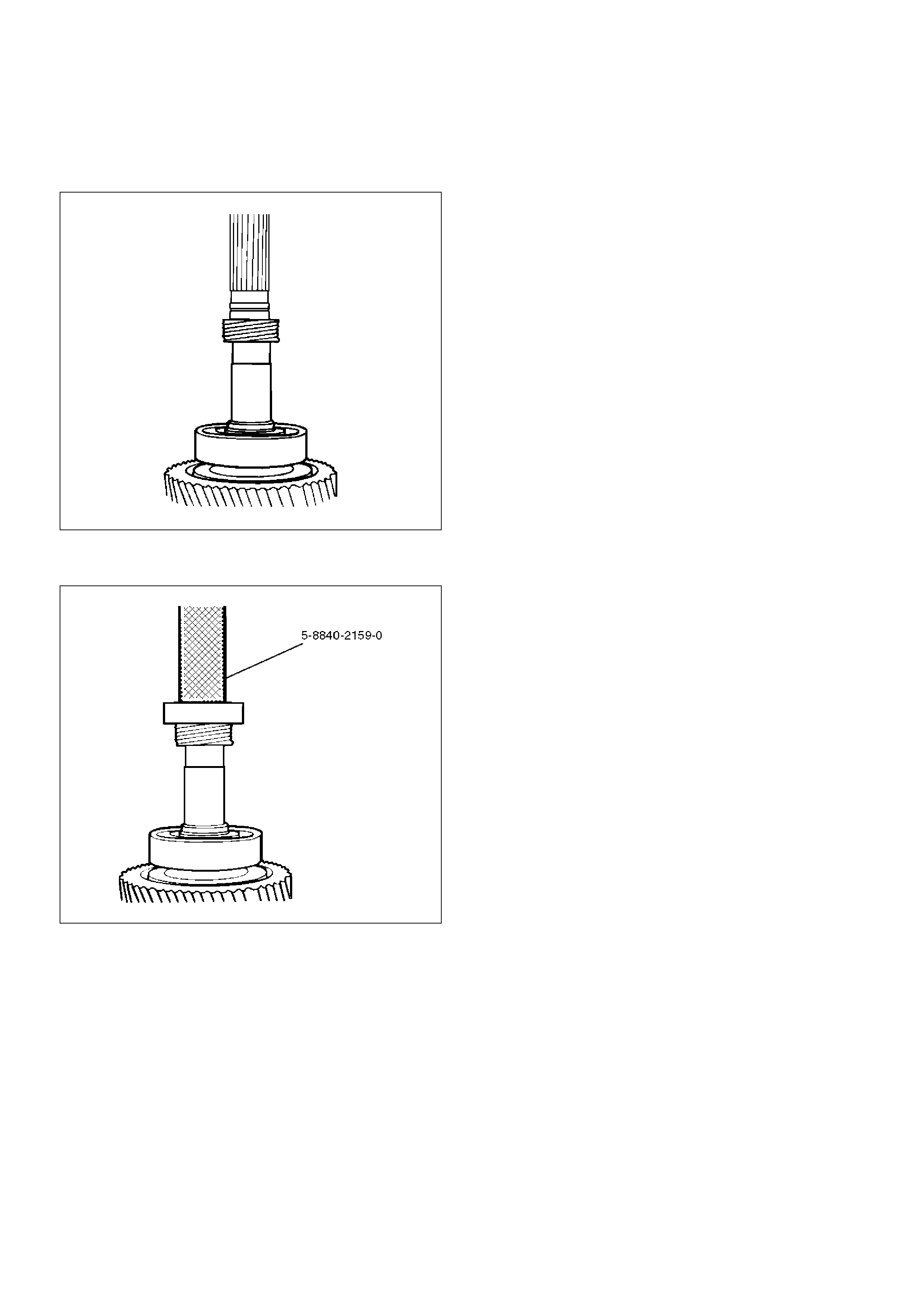
6. Install ball bearing (8), using the ball bearing
installer 5–8840–2159–0 (J–37223).
226RW188
7. Install the rear output shaft assembly (1) to the
transfer rear cover.
8. Install the bearing snap ring (3).
NOTE: The snap ring must be fully inserted into the
transfer rear case snap ring groove.
Transfer Rear Cover Assembly (Except 4WD Switch Model)
Transfer Rear Cover Assembly and Associated Parts
220RW116
EndOFCallout
Legend
(1) Speedometer Sensor, Speedometer Driven
Gear and Plate
(2) Front Companion Flange
(3) Rear Companion Flange
(4) Control Box Assembly
(5) Transfer Rear Cover Assembly
(6) Transfer Case Assembly
Removal
1. Remove the speedometer sensor.
2. Remove the plate.
3. Remove the speedometer driven gear bushing and
driven gear.
NOTE: Apply a reference mark to the driven gear
bushing before removal.
4. Remove the front companion flange and the rear
companion flange, using the flange companion
holder 5–8840–0133–0 (J–8614–11) to remove the
end nuts.
262RW067
NOTE: Use a universal puller to remove the rear
companion flange.
5. Disconnect the transfer breather hose from the
control box.
6. Remove the control box assembly.
7. Remove the transfer rear cover assembly from the
transfer case assembly.
Installation
1. Apply the recommended liquid gasket (LOCTITE
17430) or its equivalent to the transfer rear cover
fitting faces.
220RS017
2. Install the transfer rear cover assembly to the
transfer case assembly.
3. Perform the following steps before fitting the transfer
rear case:
1. Shift the high–low shift rod to the 4H side.
2. Turn the select rod counterclockwise so that the
select block projection may enter into the 2WD–
4WD shift block.
3. The cut–away portion of the select rod head (9)
should align with that of the rear case hole's
stopper (10).
230RW004
4. Tighten the transfer rear case bolts to the specified
torque.
Torque: 37 N·m (3.8kg·m/27 lbft)
5. Install the control box assembly.
Torque: 19 N·m (1.9kg·m/14 lbft)
6. Connect the breather hoses to the control box.
7. Install the rear companion flange and front
companion flange, using the companion flange
holder 5–8840–0133–0 (J–8614–11) to tighten the
flange nuts to the transfer case.
262RW067
8. Tighten the new transfer flange nuts to the specified
torque.
Torque
Rear companion flange: 167 N·m (17.0kg·m/123
lbft)
Front companion flange: 137 N·m (14.0kg·m/101
lbft)
9. Use the punch 5–8840–2293–0 (J–39209) to stake
the rear companion flange nut at two spots.
266RW027
266RW002
10. Stake the front companion flange nut at one spot.
NOTE: Be sure to confirm that there is no crack at the
staked portion of the flange nut after staking.
11. Install the O–ring (8) to the speedometer driven
gear bushing (7).
12. Install the driven gear to the speedometer driven
gear bushing (7).
13. Install the speedometer driven gear assembly to the
transfer rear cover.
14. Install the plate (6) to the transfer rear case and
tighten to the specified torque.
Torque: 15 N·m (1.5kg·m/11 lbft)
15. Install the speedometer sensor and tighten to the
specified torque.
Torque: 27 N·m (2.8kg·m/20 lbft)
225RW014

Disassembly
226RW154
EndOFCallout
1. Remove the bearing snap ring (3), using a pair of
snap ring pliers.
226RS060
Legend
(1) Rear Output Shaft Assembly
(2) Rear Output Shaft
(3) Bearing Snap Ring
(4) Ball Bearing
(5) Bearing Snap Ring
(6) Ball
(7) Speedometer Drive Gear
(8) Ball Bearing
(9) Transfer Rear Cover (with oil seal)

2.Remove the rear output shaft assembly (1) from the
transfer rear cover (with oil seal).
3.Remove ball bearing (8), using a bench press and
the bearing remover 5–8840–0015–0 (J–22912–
01) .
226RW186
4.Remove the speedometer drive gear (7).
5.Remove the ball (6).
6.Remove the bearing snap ring (5), using a pair of
snap ring pliers.
7.Remove the ball bearing (4) from the rear output
shaft, using a bench press and the bearing remover
5–8840–0015–0 (J–22912–01).
226RW187
Inspection and Repair
Refer to “TRANSFER CASE ASSEMBLY” in this section
for inspection and repair.
Reassembly
1. Install transfer rear cover (with oil seal).
Oil seal replacement
• Remove the oil seal from the transfer rear cover.
• Apply engine oil to the oil seal outer surfaces.
• Fill in recommended grease (BESCO L2) or
equivalent in the oil seal lip.
• Use the oil seal installer 5–8840–2292–0 (J–
39208) to install the rear oil seal to the transfer
rear cover.
220RW104
2. Set the snap ring (3), and install ball bearing (4) to
the rear output shaft (2), using the ball bearing
installer 5–8840–2159–0 (J–37223) and the adapter
5–8840–2192–1 (J–37486–A).
262RW068

3. Install the bearing snap ring (5).
4. Install the ball (6).
5. Install the speedometer drive gear (7).
226RS064
6. Install ball bearing (8), using the ball bearing
installer 5–8840–2159–0 (J–37223).
226RW188
7. Install the rear output shaft assembly (1) to the
transfer rear cover.
8. Install the bearing snap ring (3).
NOTE: The snap ring must be fully inserted into the
transfer rear case snap ring groove.
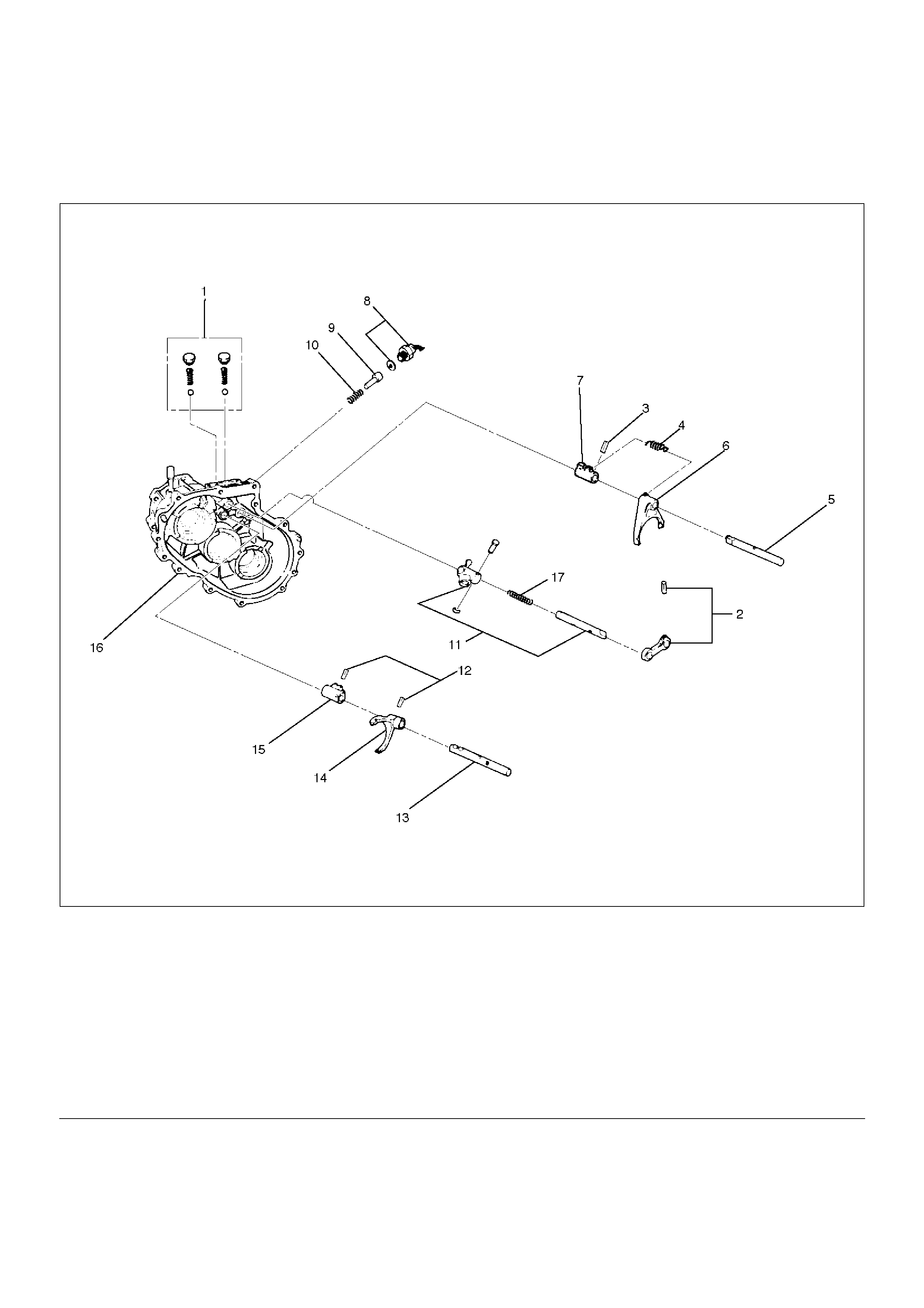
Detent, Shift Arm, and Interlock Pin
Disassembled View
262RW074
EndOFCallout
Disassembly
1. Remove the detent ball, spring and plug (1).
Legend
(1) Detent Ball, Spring and Plug
(2) Spring Pin and Bridge
(3) Spring Pin
(4) Spring
(5) 2WD–4WD Shift Rod
(6) Shift Arm
(7) Shift Block
(8) 4WD Indicator Switch
(9) Interlock Pin
(10) Spring
(11) Select Rod Assembly
(12) Spring Pin
(13) High–Low Shift Rod
(14) Shift Arm
(15) Shift Block
(16) Transfer Case
(17) Spring (Except Shift On The Fly Model)
2. Use a spring pin remover to remove the spring pin
(2) from the bridge (2).
262RW011
3. Remove the spring (4).
4. Engage the 2WD–4WD sleeve with the front output
gear. Remove the spring pin (3) from the block (7).
Remove the 2WD–4WD shift rod (5).
262RW022
5. Remove the shift arm (6).
6. Remove the shift block (7).
7. Remove the 4WD indicator switch (8).
8. Use a magnetic tool to remove the interlock pin (9)
and spring (10) from the transfer case (16).
262RS005
9. Remove the select rod assembly (11).
10. Use a spring pin remover to remove the shift arm
spring pins (12) from the shift arm (14) and shift
block (15). Remove the high–low shift rod (13) from
the transfer case (16).
262RS006
11. Remove the shift arm (14).
12. Remove the shift block (15) from the transfer case
(16).

Inspection and Repair
Refer to “TRANSFER CASE ASSEMBLY” in this section
for inspection and repair.
Reassembly
1. Place the shift block (15) in the transfer case (16).
2. Set the shift arm (14) on the High–Low sleeve.
3. Push the High–Low shift rod (13) through the shift
arm (14) and block (14).
4. Engage the High–Low sleeve with the 4H (1) side.
5. Install the spring pins (12) to the shift block (15) and
shift arm (14).
262RW012
6. Install the select rod assembly (11), joining its lever
to the shift block groove.
7. Engage the High–Low sleeve with the 4H side and
install the the interlock pin (9) and spring (10) in the
proper direction.
8. Place the 2WD–4WD shift block (7) in the transfer
case (16).
9. Set the 2WD–4WD shift arm (6) on the 2WD–4WD
sleeve.
10. Push the 2WD–4WD shift rod (5) through the
2WD–4WD shift arm (6) and 2WD–4WD shift block
(7).
11. Install the 2WD–4WD shift rod (5) with the interlock
pin pushed in.
262RW035
EndOFCallout
12. Install the 4WD indicator switch and gasket (8).
Tighten to the specified torque.
Torque: 39 N·m (4.0kg·m/29 lbft)
13. Install the spring (4).
Legend
(18) 2WD–4WD
(19) 4H Side
(20) Interlock pin
(21) 2WD
(22) 4WD
(23) Rod: 2–4
(24) Rod: H–L
(25) 4H
(26) 4L
(27) 4´2
(28) 4´4
14. Engage the 2WD–4WD sleeve with the 4WD side
and install the spring pin (3).
262RW022
15. Install the spring pin and bridge (2).
16. Install the detent ball, spring and plug and tighten
the plug (1) to the specified torque.
Torque: 25 N·m (2.5kg·m/18 lbft)
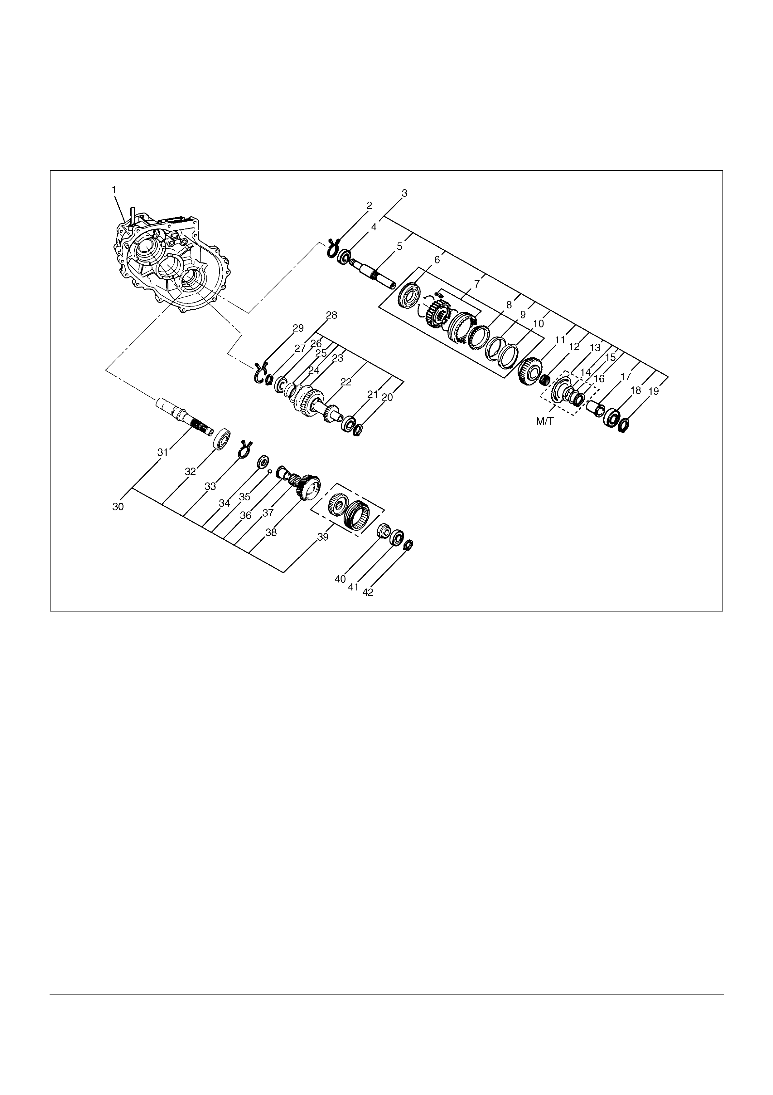
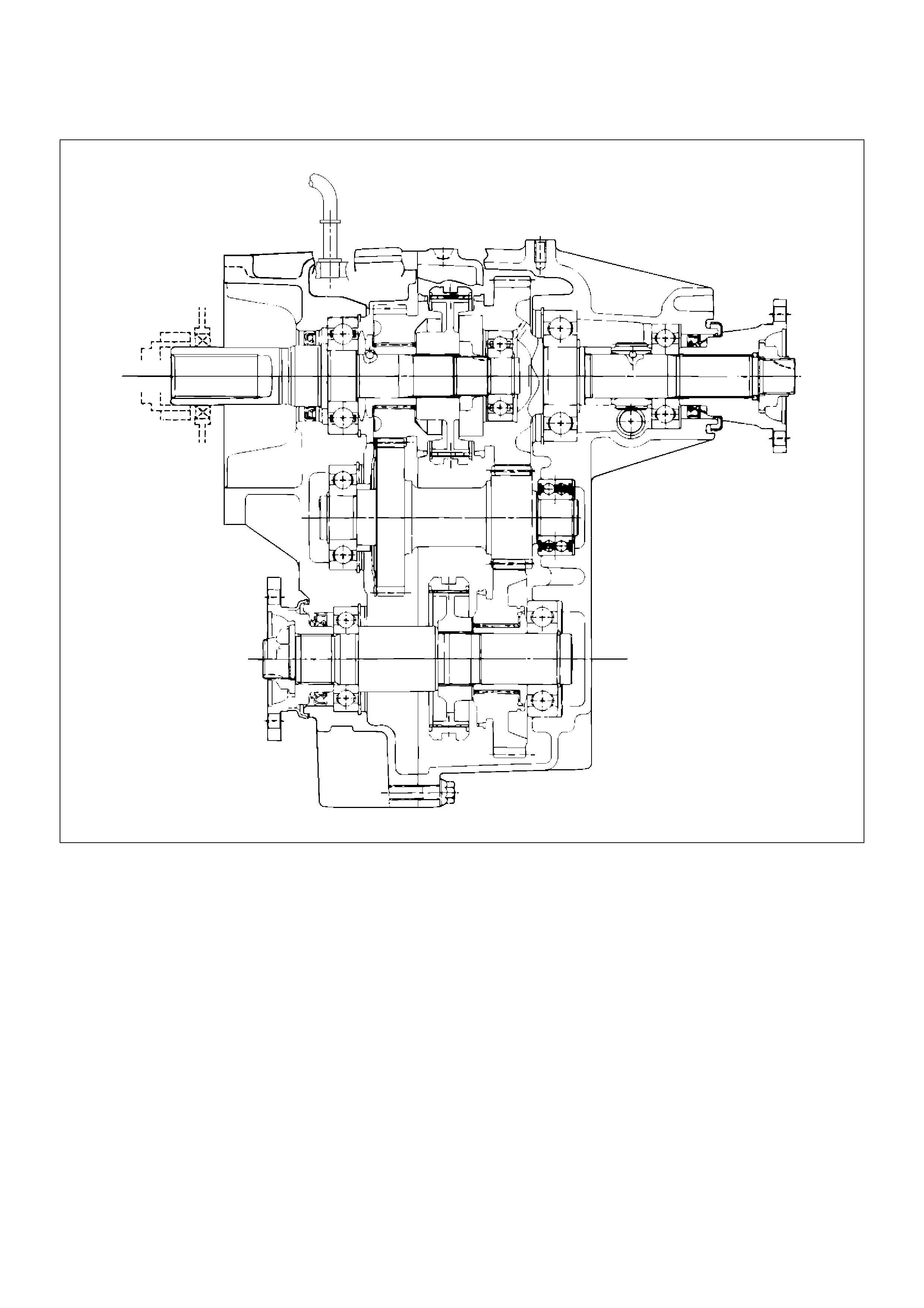
Transfer Case Assembly
Disassembled View
226RW132
EndOFCallout
Legend
(1) Transfer Case (with oil seal)
(2) Bearing Snap Ring
(3) Front Output Gear Assembly
(4) Ball Bearing
(5) Front Output Shaft
(6) Stopper Plate (Shift On The Fly model)
(7) 2WD–4WD Clutch Hub and Sleeve Assembly
(8) Block Ring (Shift On The Fly model)
(9) Outside Ring (Shift On The Fly model)
(10) Inside Ring (Shift On The Fly model)
(11) Front Output Gear
(12) Needle Bearing
(13) Sub–Gear (anti–lash plate) (M/T)
(14) Belleville Spring (M/T)
(15) Spacer (M/T)
(16) Sub–Gear Snap Ring (M/T)
(17) Bearing Collar
(18) Ball Bearing
(19) Bearing Snap Ring
(20) Snap Ring
(21) Ball Bearing
(22) Counter Gear
(23) Sub–Gear (anti–lash plate)
(24) Belleville Spring
(25) Spacer
(26) Ball Bearing
(27) Snap Ring
(28) Counter Gear Assembly
(29) Bearing Snap Ring
(30) Input Shaft Assembly
(31) Input Shaft
(32) Ball Bearing
(33) Snap Ring
(34) Plate
(35) Ball
(36) Bearing Collar
(37) Needle Bearing
(38) Transfer Input Gear
(39) High–Low Clutch Hub and Sleeve Assembly
(40) Lock Nut
(41) Ball Bearing
(42) Bearing Snap Ring
Disassembly
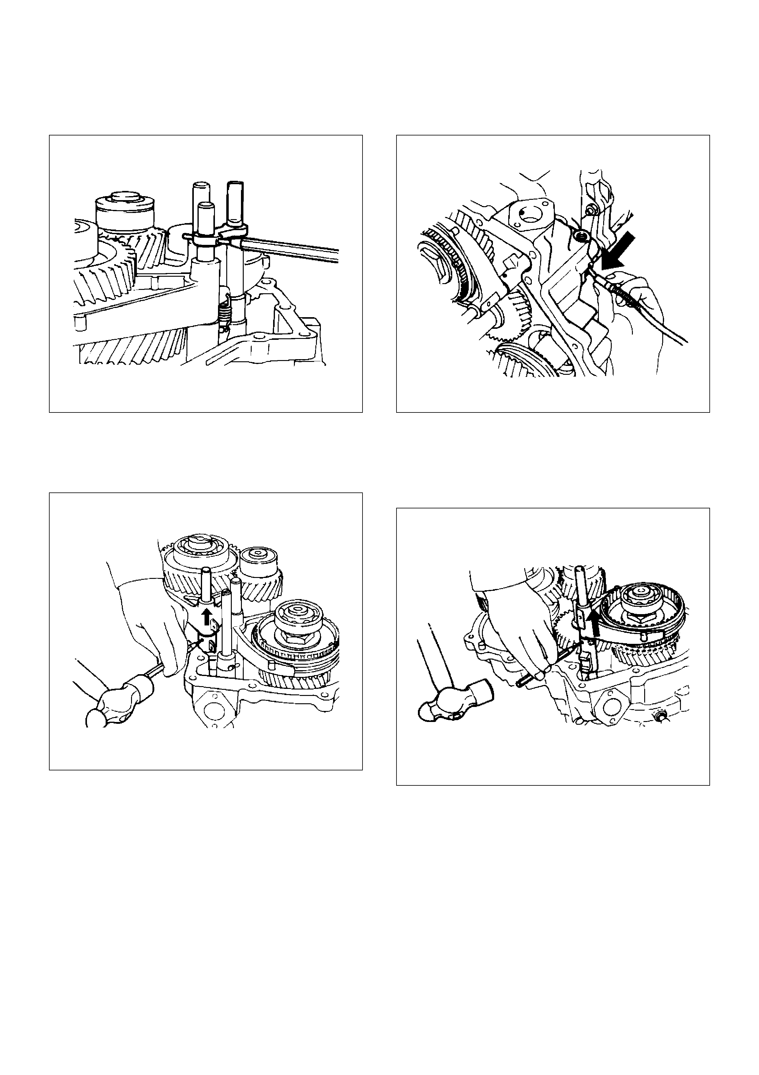
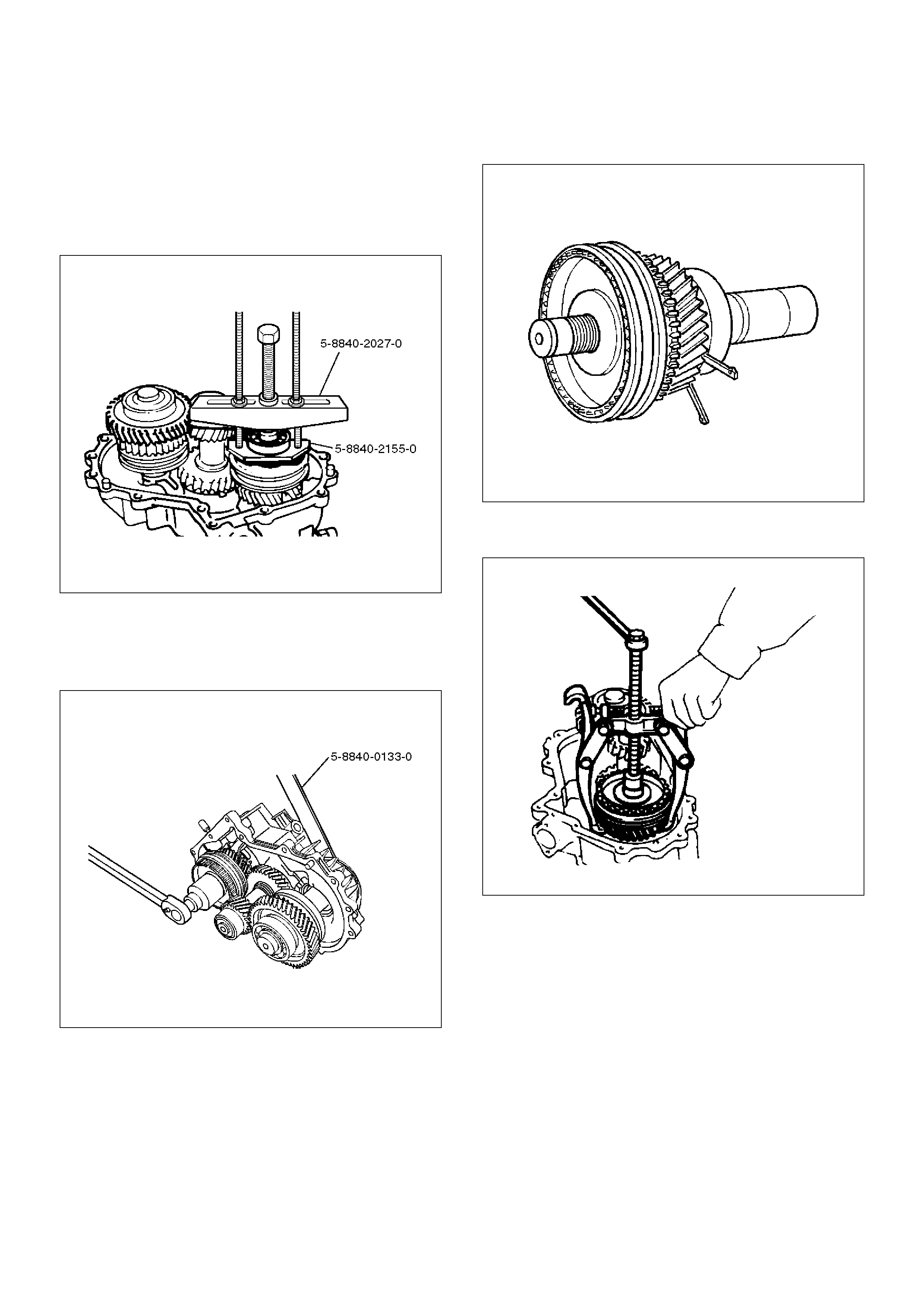
1. Use a pair of snap ring pliers to remove the snap
ring (42).
2. Use a bearing remover 5–8840–2155–0 ( J–37217)
and puller 5–8840–2027–0 (J–37487) to remove the
ball bearing (41).
262RW069
3. Install the front companion flange temporarily.
4. Use the Companion flange holder 5–8840–0133–0
(J–8614–11) and lock nut wrench 5–8840–2156–0
(J–37219) to remove the lock nut (40).
226RW189
5. Remove the front companion flange.
6. Remove the snap ring (33) from the transfer case
(1).
7. Remove the input shaft assembly (30) from the
transfer case.
265RW001
8. Use a universal puller to remove the high–low clutch
hub and sleeve (39), and transfer input gear (38).
226RS070
9. Remove needle bearing (37).
10. Remove the bearing collar (36).
226RS071
11. Remove the ball (35).
12. Remove the plate (34).
13. Use a bench press and the ball bearing remover 5–
8840–0015–0 (J–22912–01) to remove the ball
bearing (32) from input shaft (31).
265RW013
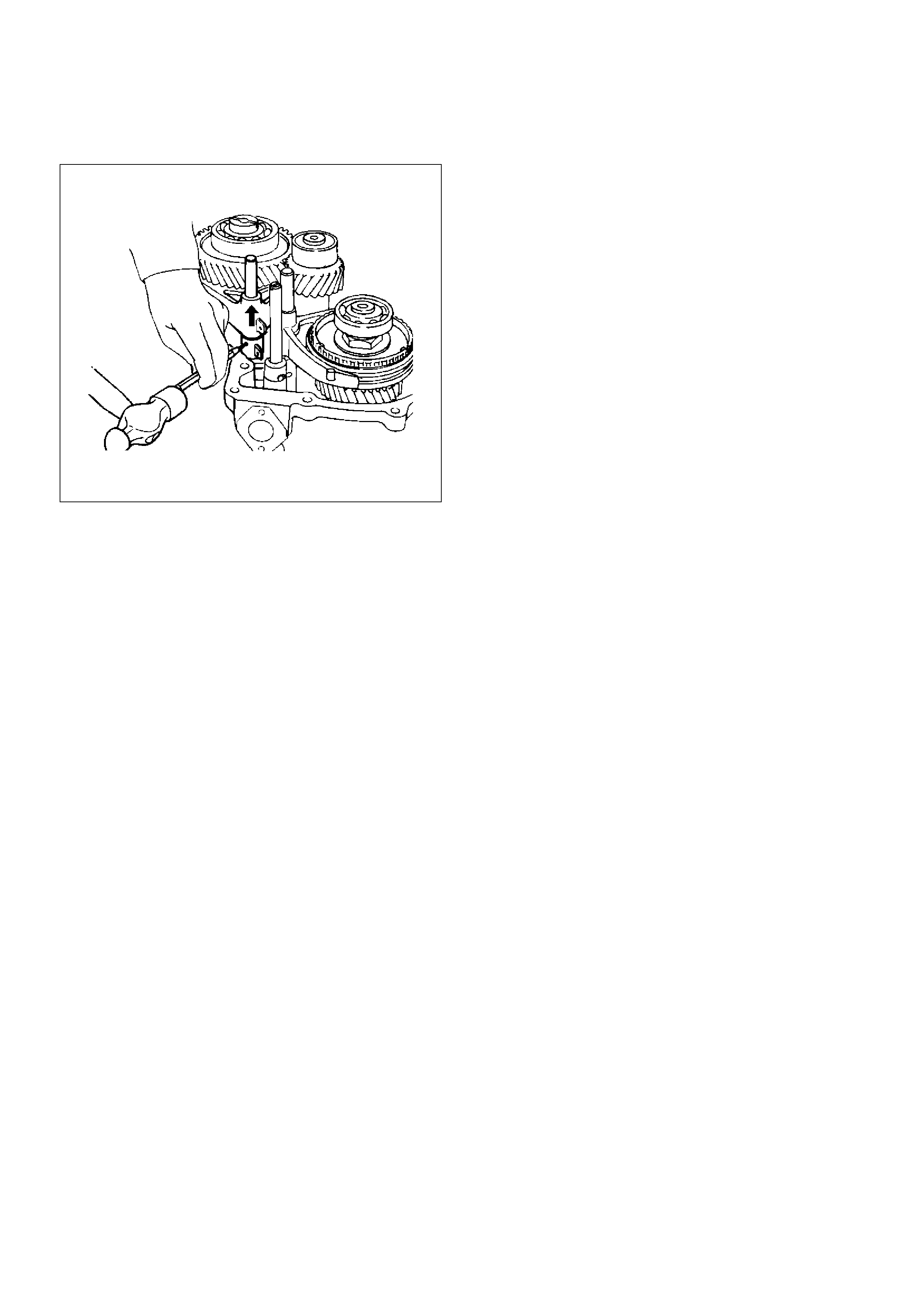
14. Remove the bearing snap ring (2) from the transfer
case, using a pair of snap ring pliers.
15. Use a plastic hammer to tap the front output gear
assembly (3) free.
262RS009
16. Remove the bearing snap ring (19). Remove the
ball bearing (18) and bearing collar (17) together
with front output gear assembly: including following
parts.
17. Use a bench press and the bearing remover 5–
8840–0015–0 (J–22912–01) to remove the
following parts.
18. Remove the sub–gear snap ring (16), spacer (15),
belleville spring (14), and sub–gear (anti–lash plate)
(13).(M/T)
19. Remove the front output gear (11) and needle
bearing (12).
262RW070
20. Remove the inside ring (10). (Shift On The Fly
model)
21. Remove the outside ring (9). (Shift On The Fly
model)
22. Remove the block ring (8). (Shift On The Fly model)
23. Use a bench press and bearing remover 5–8840–
0015–0 (J–22912–01) to remove the 2WD–4WD
clutch hub and sleeve assembly (7) and stopper
plate (6). (Shift On The Fly model)
NOTE: Do not reuse the stopper plate. (Shift On The
Fly model)
24. Disassemble the 2WD–4WD clutch hub and sleeve
assembly.
• Springs (1) (Shift On The Fly model)
• Inserts (2) (Shift On The Fly model)
• Clutch Hub (3)
• Sleeve (4)
226RW133
25. Use a bench press and the ball bearing remover 5–
8840–0015–0 (J–22912–01) to remove the ball
bearing (4) from front output shaft (5).
262RW071
26. Remove bearing snap ring (29) from transfer case.
27. Remove the counter gear assembly (28) from the
transfer case (1).
28. Use a pair of snap ring pliers to remove the snap
ring (20).
29. Use a bench press and the bearing remover 5–
8840–0015–0 (J–22912–01) to remove the ball
bearing (21).
30. Use a pair of snap ring pliers to remove the snap
ring (27).
31. Use a bench press and the bearing remover 5–
8840–0015–0 (J–22912–01) to remove the ball
bearing (26).
226RW191
32. Remove the spacer (25).
33. Remove the belleville spring (24).
34. Remove the sub–gear (anti–lash plate) (23) from
the counter gear (22).
Inspection and Repair
1. Make the necessary repair or parts replacement if
wear, damage or any other abnormal conditions are
found during inspection.
2. Wash all parts thoroughly in clean solvent. Be sure
all old lubricant, metallic particles, dirt, or foreign
material are removed from the surfaces of every
part. Apply compressed air to each oil feed port and
channel in each case half to remove any
obstructions or cleaning solvent residue.
Gears
1. Inspect all the gear teeth for signs of excessive
wear or damage and check all the gear splines for
burrs, nicks, wear or damage. Remove the minor
nicks or scratches on an oil stone. Replace any part
exhibiting excessive wear or damage.
Front Output Gear Inside Diameter
1. Use an inside dial indicator to measure the gear
inside diameter.
2. If the measured value exceeds the specified limit,
the gear must be replaced.
Gear inside diameter
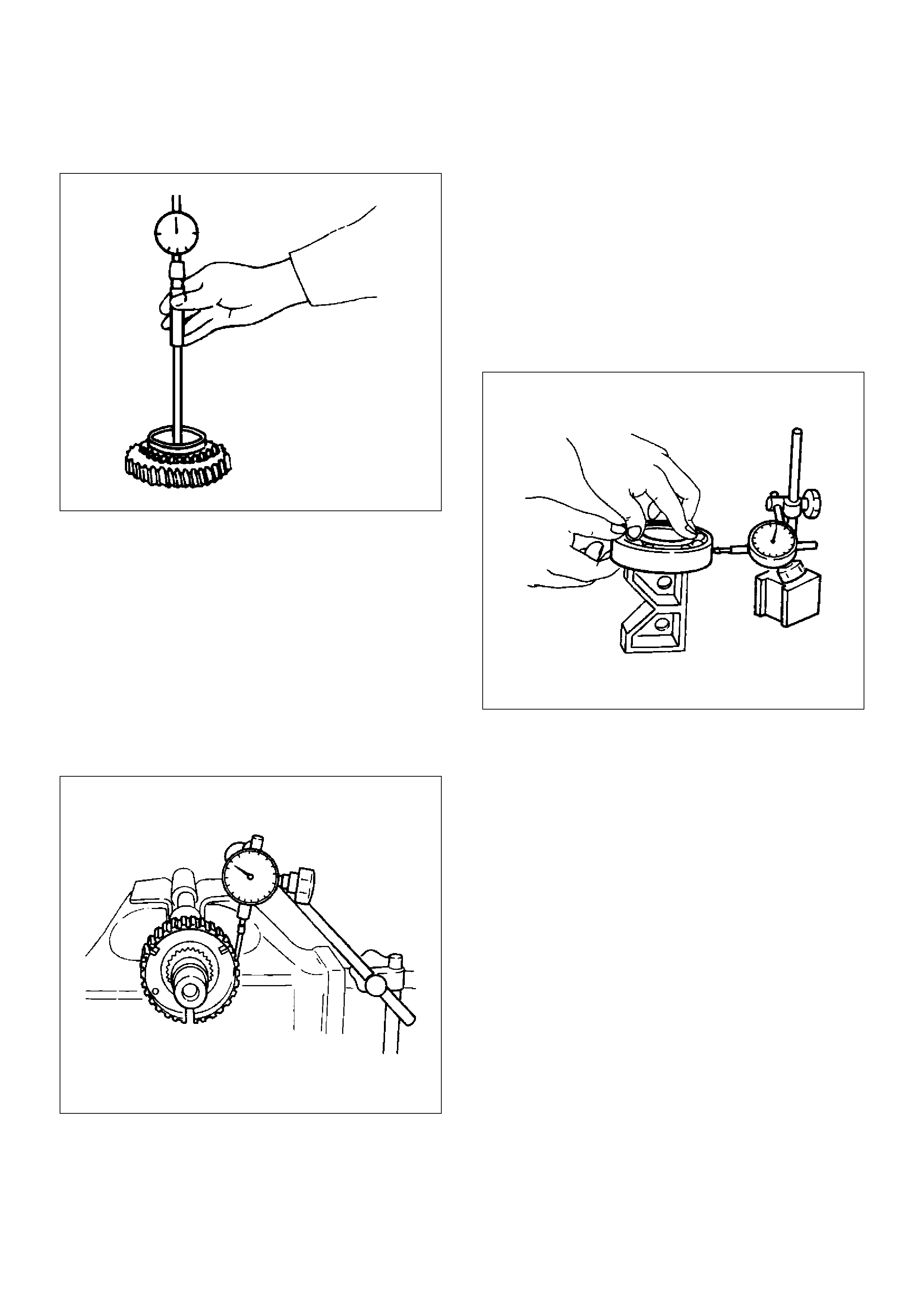
Standard : 48.000–48.013 mm (1.8898–1.8903 in)
Limit : 48.10 mm (1.894 in)
226RS040
Clutch Hub Spline Play
1. Set a dial indicator to the clutch hub to measured.
2. Move the clutch hub as far as possible to both the
right and the left.
Note the dial indicator reading.
3. If the measured value exceeds the specified limit,
the clutch hub must be replaced.
Clutch hub spline play
Standard : 0–0.1 mm (0–0.004 in)
Limit : 0.2 mm (0.008 in)
226RS042
Bearings
1. Inspect the condition of all the needles and ball
bearings. Wash bearings thoroughly in a cleaning
solvent. Apply compressed air to the bearings.
NOTE: Do not allow the bearings to spin. Turn them
slowly by hand. Spinning bearings may damage the
rollers.
2. Lubricate the bearings with a light oil and check
them for roughness by slowly turning the race by
hand.
Ball Bearing Play
1. Use a dial indicator to measure the ball bearing play.
2. If the measured value exceeds the specified limit,
the ball bearing must be replaced.
Limit : 0.2 mm (0.008 in)
226RS043
Synchronizers
The synchronizer hubs and sliding sleeves are a
selected assembly and should be kept together as
originally assembled.
Clean synchronizer components with clean solvent and
air dry.
Inspect the components for the following:
• Teeth for wear, scuffs, nicks, burrs or breaks.
• Keys and springs for wear, cracks or distortion,
replace if these conditions are present.
• If scuffed, nicked or burred conditions cannot be
corrected with a soft stone or crocus cloth, replace
the component.
Block Ring and Insert Clearance
1. Use a vernier caliper to measure the clearance
between the block ring and the insert.
2. If the measured value exceeds the specified limit,
the block ring and the insert must be replaced.
Block ring and insert clearance
Standard : 2.46–2.74 mm (0.097–0.108 in)
Limit : 3.0 mm (0.118 in)
226RS037
2WD–4WD 3–Cone Synchronizer (Shift On
The Fly model)
1. Use a thickness gauge to measure the clearance
between the block ring and the dog teeth.
2. If the measured value exceeds the specified limit,
the 2WD–4WD synchronizer assembly must be
replaced.
Block ring and insert clearance
Standard : 1.5 mm (0.059 in)
Limit : 0.8 mm (0.031 in)
226RW142
Clutch Hub and Insert Clearance
1. Use a thickness gauge to measure the clearance
between the clutch hub and the insert.
2. If the measured value exceeds the specified limit,
the clutch hub and the insert must be replaced.
Clutch hub and insert clearance
Standard : 0.01–0.19 mm (0.0004–0.0075 in)
Limit : 0.3 mm (0.012 in)
226RS038
Detent Springs
1. Inspect the springs for distortion, cracks or wear.
Replace if these conditions are present.
Detent Spring Free Length
1. Use a vernier caliper to measure the detent spring
free length.
2. If the measured value is less than the specified limit,
the detent spring must be replaced.
Detent spring free length
Detent ball
Standard : 23.4 mm (0.921 in)
Limit : 22.8 mm (0.898 in)
Interlock pin
Standard : 1.59 mm (0.063 in)
Limit : 1.53 mm (0.060 in)
220RW035
Detent Spring Tension
1. Use a spring tester to measure the detent spring
tension.
2. If the measured value is less than the specified limit,
the detent spring must be replaced.
Detent spring free length
Detent ball
Compressed height : 18.7 mm (0.736 in)
Standard : 68.6–88.2 N (7.0–9.0kg/15.4–19.8 lb)
Interlock pin
Compressed height : 11.5 mm (0.453 in)
Standard : 9.8 N (1.0kg/2.2 lb)
220RS013
Shift Arm
1. Inspect the shift arms for wear, distortion or scoring.
Replace if these conditions are present.
Shift Arm Thickness
1. Use a micrometer to measure the shift arm
thickness.
2. If the measured value is less than the specified limit,
the shift arm must be replaced.
Shift arm thickness
Standard : 9.60–9.85 mm (0.378–0.388 in)
Limit : 9.0 mm (0.354 in)
230RS006

Reassembly
1. Put the transfer case (with oil seal) as the following
illustration.
Input shaft oil seal (1) replacement
1. Remove the oil seal from the transfer case.
2. Apply engine oil to the oil seal outer surfaces.
3. Apply recommended grease (BESCO L2) or
equivalent to the oil seal lip.
4. Use the oil seal installer 5–8840–2279–0 (J–
38592) to install the oil seal to the transfer case.
220RW106
Front output shaft oil seal (2) replacement
1. Remove the oil seal from the transfer case.
2. Apply engine oil to the oil seal outer surfaces.
3. Apply recommended grease (BESCO L2) or
equivalent to the oil seal lip.
4. Use the oil seal installer 5–8840–2281–0 (J–
38594) to install the oil seal to the transfer case.
220RW107
EndOFCallout
2. Apply chassis grease (3) to the sub–gear (23) and
the counter gear (22) thrust surfaces.
226RW134
Legend
(2) Front output shaft oil seal
3. Install the sub–gear (23) to the counter gear (22).
4. Install the belleville spring (24).
5. Install the spacer (25) and put the snap ring (29) on
the sub–gear (23).
6. Install the ball bearing (26), using a bench press.
7. Select a snap ring that will allow the minimum axial
play.
Clearance : 0–0.1 mm (0–0.004 in)
8. Use a pair of snap ring pliers to install the snap ring
(27) to the counter gear (22).
226RS170
226RS021
Sub–Gear (anti–lash plate) Preload
1. Hook a length of piano wire (4) over one of the
sub–gear (5) teeth.
2. Attach the other end of the piano wire (4) to a
spring balancer.
3. Measure the sub–gear preload.
Preload : 59–98 N (6.0–10kg/13–22 lb)
226RS075
9. Install ball bearing (21), using a bench press.
10. Install snap ring (20).
11. Install the counter gear assembly (28) to the transfer
case (1).
12. Use a pair of snap ring pliers to install the snap ring
(29) to the transfer case (1).
NOTE: The snap ring must be fully inserted into the
transfer case snap ring groove.
13. Use a bench press to install the ball bearing (4) to
the front output shaft (5).
262RS012
Snap ring availability:
Thickness Color–coding
1.50 mm (0.059 in) White
1.55 mm (0.061 in) Yellow
1.60 mm (0.063 in) Blue
14. Assemble the 2WD–4WD clutch hub and sleeve
assembly (7).
226RW140
15. Engage the springs in the same insert with the open
ends away from each other. (Shift On The Fly
model)
226RW141
16. Place the snap ring (2), a new stopper plate (6)
(Shift On The Fly model) and the clutch sleeve and
hub assembly (7) on the front output shaft (5).
226RW135
EndOFCallout
17. The clutch hub face (with the heavy boss) must be
facing the front output gear side.
18. Use a bench press to slowly force the clutch hub
and sleeve assembly (7) together with the stopper
plate (6) (Shift On The Fly model) into place.
19. Align the inserts with the block ring insert grooves.
Install the block ring (8) (Shift On The Fly model) to
the clutch sleeve and hub assembly (7).
20. Install the outside ring (9) (Shift On The Fly model),
inside ring (10) (Shift On The Fly model) and needle
bearing (12) to the front output gear (11) and
bearing collar (17).
NOTE: Coat all parts with transmission oil before
installing them.
226RW139
Legend
(6) Front Output Gear
21. Apply engine oil to the thrust surfaces of the sub–
gear (13), the belleville spring (14), and the spacer
(15). (M/T)
262RW060
22. Install the sub–gear (anti–lash plate) (13), belleville
spring (14), and spacer (15) to the front output gear
(11).(M/T)
23. Install the sub–gear snap ring (16). (M/T)
24. Use a bench press to install the needle bearing
collar (17) together with the front output gear,
aligning inside ring claw with block ring groove.
262RS014
25. Install ball bearing (18), using a bench press.
26. Select a snap ring that will allow the minimum axial
play.
Clearance : 0–0.1 mm (0–0.004 in)
262RS015
226RS021
Snap ring availability:
Snap ring thickness Color coding
1.55 mm (0.061 in) White
1.60 mm (0.063 in) Yellow
1.65 mm (0.065 in) Blue
1.70 mm (0.067 in) Pink
1.75 mm (0.069 in) Green
1.80 mm (0.071 in) Brown
1.85 mm (0.073 in) Red
1.90 mm (0.075 in) Orange
27. Use a pair of snap ring pliers to install the snap ring
(19) to the output shaft (5).
Sub gear (anti lash plate) preload (M/T)
1. Hook a length of piano wire (4) over one of the
sub–gear (5) teeth.
2. Attach the other end of the piano wire to (4) a
spring balancer.
3. Measure the sub–gear preload.
Preload: 59–98 N (6.0–10.0kg/13–22 lb)
(M/T)
226RS075
28. Install front output gear assembly (3) to the transfer
case (1).
29. Use a pair of snap ring pliers to install the snap ring
(2) to the transfer case (1).
NOTE: The snap ring must be fully inserted into the
transfer case snap ring groove.
30. Use a bench press to install the ball bearing (32) to
the input shaft (31).
265RS003
31. Install the plate (34), ball (35), and bearing collar
(36) and place the snap ring (33).
32. Install the needle bearing (37) and input gear (38).
33. The clutch hub face (with the heavy boss) must be
facing the transfer input gear side (7).
226RW136
34. Install the high–low clutch hub and sleeve (39),
using a bench press.
35. Install the input shaft assembly (30) to the transfer
case (1).
36. Install the snap ring (33) to the transfer case (1).
NOTE: The snap ring must be fully inserted into the
transfer case snap ring groove.
37. Install the front companion flange temporarily and
use the flange holder 5–8840–0133–0 (J–8614–11)
and lock nut wrench 5–8840–2156–0 (J–37219) to
install the lock nut (40).
Torque: 137 N·m (14.0kg·m/101 lbft)
226RW190
38. Use the punch to stake the lock nut (40) at one spot.
39. Use a suitable drift and hammer to install the ball
bearing (41).
226RS079
40. Install the bearing snap ring (42).
Main Data and Specifications
General Specifications
Torque Specifications
E07RW037
Type W/Shift On The Fly System model
Synchronized type gears shifting between the 2 and 4 wheel drive mode.
Constant mesh type gears shifting between “low” and“high”.
WO/Shift On The Fly System model
Constant mesh type gears shifting between the 2 and 4 wheel drive mode,
and between “low” and“high”.
Control method W/4WD Switch model
Electric control with the button switch on the instrument panel for gear
shifting between the 2 and 4 wheel drive mode.
Remote control with the gear shift lever on the floor for gear shifting between
“low and high” .
WO/4WD Switch model
Remote control with the gear shift lever on the floor for gear shifting.
Gear ratio High; 1.000
Low; 2.050
Oil capacity 1.45 lit. (1.53 U.S. quart)
Type of lubricant Engine oil
Refer to chart in Section 0
E07RW039
E07RW038
Special Tools
ILLUSTRATION PART NO.
PART NAME
5–8840–0015–0
(J–22912–01)
Bearing remover/installer
5–8840–2279–0
(J–38592)
Transfer case oil seal
installer
5–8840–2156–0
(J–37219)
Mainshaft nut wrench
5–8840–2159–0
(J–37223)
Rear output shaft and
bearing installer
5–8840–2293–0
(J–39209)
Punch, end nut
5–8840–2281–0
(J–38594)
Front output shaft oil seal
installer
5–8840–2292–0
(J–39208)
Rear oil seal installer
5–8840–2192–1
(J–37486–A)
Bearing installer adapter
5–8840–0133–0
(J–8614–11)
Flange holder
5–8840–2155–0
(J–37217)
Mainshaft end bearing
remover
5–8840–2027–0
(J–37487)
Puller
5–8840–0007–0
(J–8092)
Driver handle
ILLUSTRATION PART NO.
PART NAME