
SECTION 9A - POWER STEERING
General Description
Power Steering Gear
Hydraulic Pump
Pressure Switch ( 6VE1 Engine)
Power Steering System Test
On-Vehicle Service
Bleeding The Power Steering System
Flushing The Power Steering System
Steering Gear
Power Steering Pump ( 6VE1 Engine)
Power Steering Pump (4JX1 Engine)
Unit Repair
Steering Gear
Power Steering Pump ( 6VE1 Engine)
Power Steering Pump (4JX1 Engine)
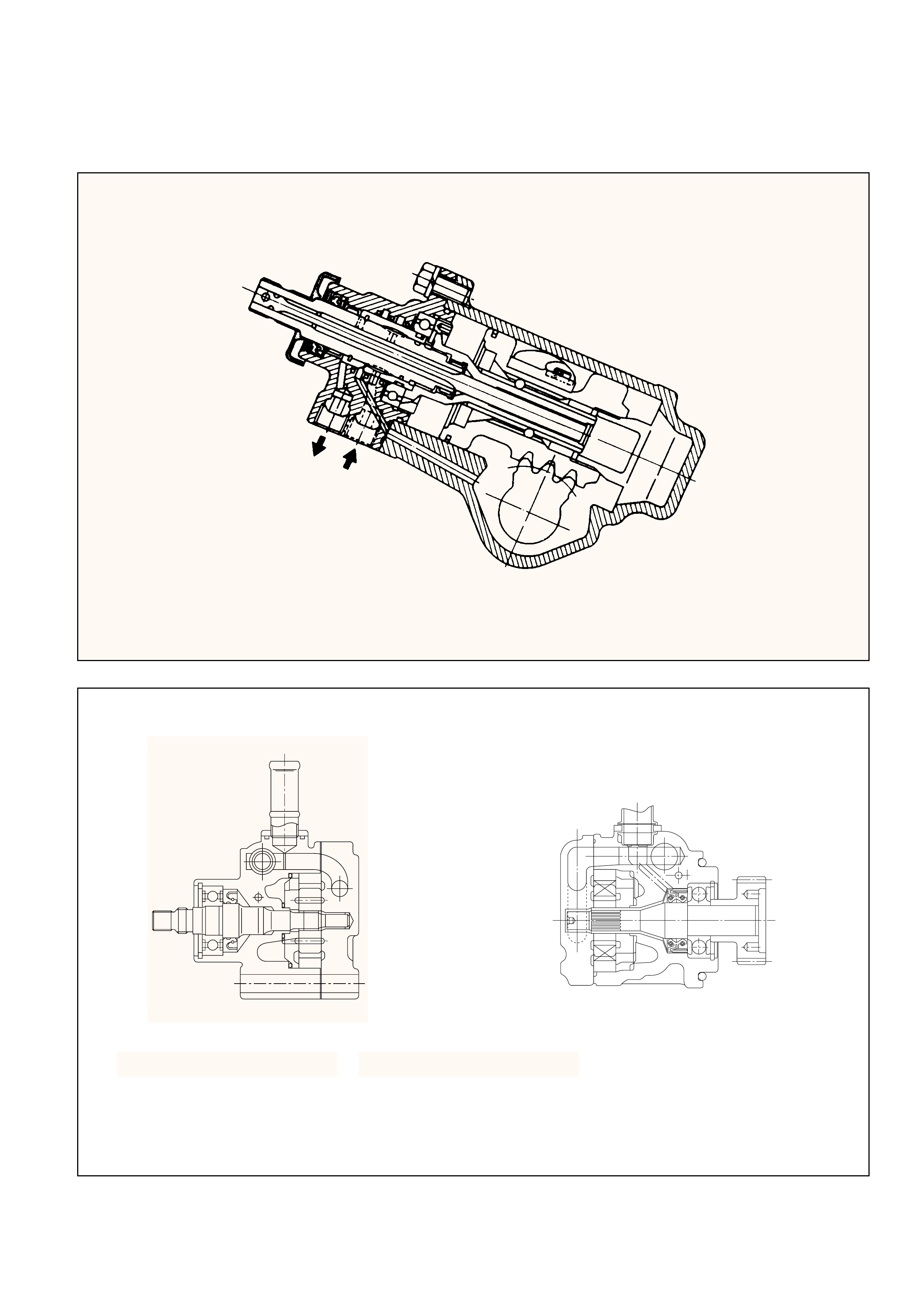
GENERAL DESCRIPTION
6VE1 Engine
4JX1 Engine

The hydraulic power steering system consists of a
pump, an oil reservoir, a steering gear, a pressure
hose and a return hose.
POWER STEERINGGEAR
The power steering gear has a recirculating ball
system which acts as a rolling thread between the
worm shaft and the rack piston. When the worm
shaft is turned right, the rack piston moves up in
gear. Turning the worm shaft left moves the rack
piston down in gear. The rack piston teeth mesh
with the sector, which is part of the sector shaft.
Turning the worm shaft turns the sector shaft,
which turns the wheels through the steering
linkage.
The control valve in the steering gear directs the
power steering fluid to either side of the rack
piston. The rack piston converts the hydraulic
pressure into a mechanical force. If the steering
system becomes damaged and loses hydraulic
pressure, the vehicle can be controlled manually.
HYDRAULICPUMP
The hydraulic pump is vane-type design.
There are two bore openings at the rear of the
pump housing. The smaller opening contains the
pressure line union and flow control valve.
PRESSURESWITCH (6VE1
ENGINE)
When hydraulic pressure reaches 3650 ± 350 kPa
(530 ±50 PSI), the pressure switch closes causing
ECM to actuate the idle air control valve to prevent
the overload-induced engine speed drop. The
switch opens when hydraulic pressure drops to
3150 ± 350 kPa (460 ± 50PSI).
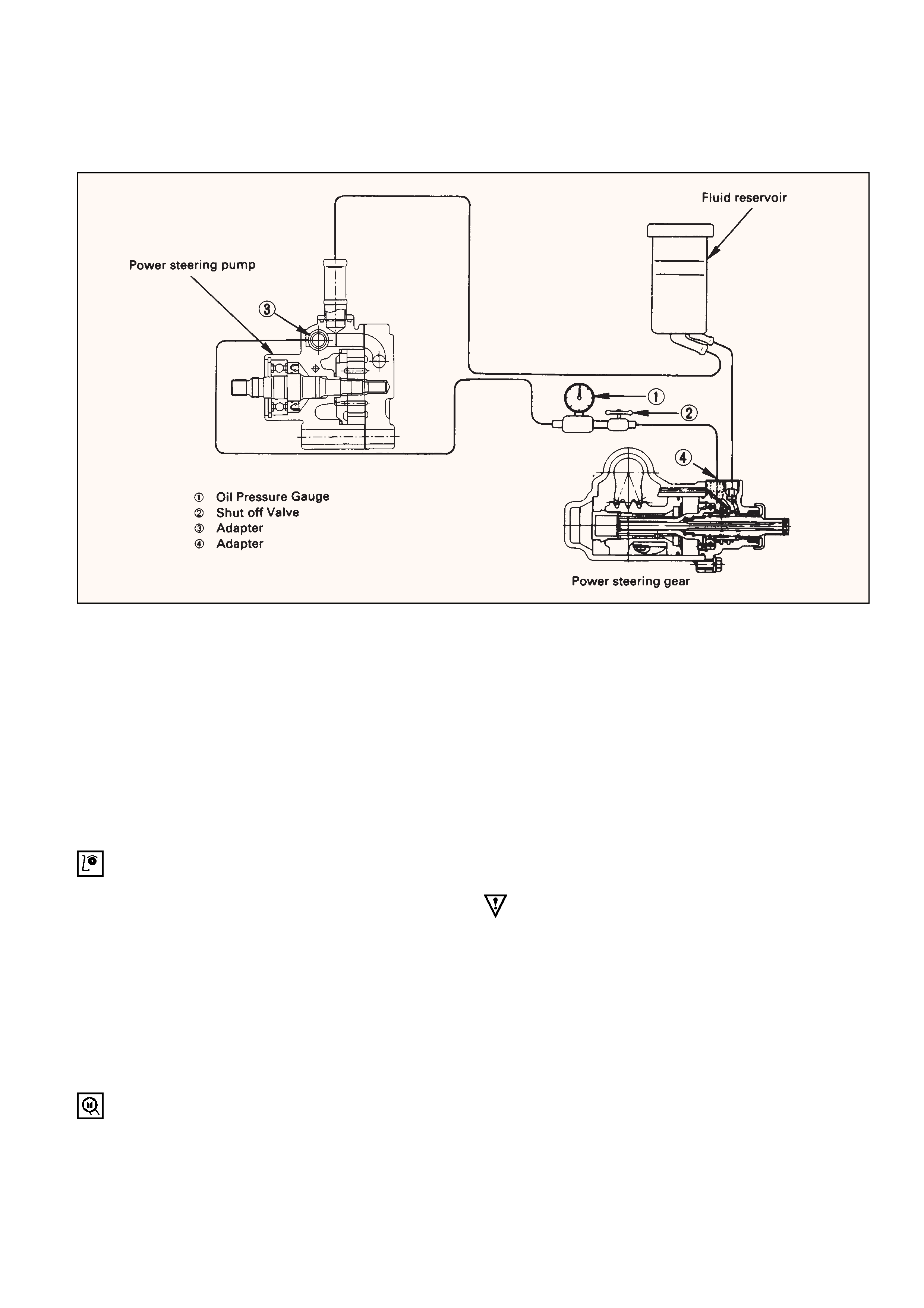
POWER STEERING SYSTEM TEST
TEST PROCEDURE
Test of fluid pressure in the power steering system
is performed to determine whether or not the oil
pump and power steering unit are functioning
normally.
The power steering system test is method used to
identify and isolate hydraulic circuit difficulties.
Prior to performing this test, the following
inspections and corrections, if necessary, must be
made.
INSPECT
•Pump reservoir for proper fluid level.
•Pump belt for proper tension.
•Pump driver pulley condition.
1.Place a container under the pump to catch the
fluid when disconnecting or connecting the
hoses.2. With the engine NOT running , disconnect the
pressure hose at the power steering pump and
install Power Steering tester.
The gage must be between the shutoff valve
and pump. Open the shutoff valve.
Tester: 5-8840-0135-0 (J-29877-A)Adapter: 5-8840-2297-0
3. Check the fluid level. Fill the reservoir with
power steering fluid, to the “Full” mark. Start
the engine then turn the steering wheel andmomentarily hold it against a stop. Turn off
and check the connections at tester for leakage.4. Bleed the system. Refer to “Bleeding the
Power Steering System” in this section.
5. Start the engine and check the pump fluid
level. Add power steering fluid if required.
When the engine is at normal operating
temperature, increase engine speed to 1500
rpm.
CAUTION:
Do not leave shutoff valve fully closed for more
than 5 seconds, as the pump could become
damaged internally.
6. Fully close the shutoff valve. Record the
highest pressures.
•If the pressure recorded is within 9300-9800
kPa (1350-1420 psi) For 6VD1, 6VE1, and
9800-10300 kPa (100-105 kg/cm2/ 1420-1490
psi) For 4JG2, 4JX1, the pump is functioning
within its specifications.
•If the pressure recorded is higher than 9800
kPa (1420 psi) For 6VD1, 6VE1, and 10300
kPa (105 kg/cm2/ 1490 psi) For 4JG2, 4JX1,
the valve in the pump is defective.

· If the pressure recorded is lower than 9300
kPa (1350 psi) For 6VE1, and 9800 kPa
(100 kg/cm 2/ 1420 psi) For 4JX1, the
valve or the rotating group in the pump is
defective.
7. If the pump pressure are within specifications,
leave the valve open and turn (or have
someone else turn) the steering wheel fully in
both directions. Record the highest pressures
and compare with the maximum pump
pressure recorded in step 6. If this pressure
cannot be built in either (or one) side of the
power steering gear, the power steering gear is
leaking internally and must be disassembled
and repaired.
8. Shut the engine off, remove the testing gage,
reconnect the pressure hose, check the fluid
level and make the needed repairs.
9. If the problem still exists, the steering and front
suspension must be thoroughly examined.

BLEEDINGTHEPOWER
STEERING SYSTEM
When a power steering pump or gear has been
installed, or an oil line has been disconnected, the
air that has entered the system must be bled out
before the vehicle is operated. If air is allowed to
remain in the power steering fluid system, noisy
and unsatisfactory operation of the system may
result.
BLEEDING PROCEDURE
When bleeding the system, and any time fluid is
added to the power steering system, be sure to use
only power steering fluid as specified in
“MAINTENANCE ANDLUBRICATION” in section
0B.
1.Fill the pump fluid reservoir to the proper
level and let the fluid settle for at least two
minutes.
2.Start the engine and let it run for a few
seconds.
Do not turn the steering wheel. Then turn the
engine off.
3.Add fluid if necessary.
4.Repeat the above procedure until the fluid
level remains constant after running the
engine.
5.Raise the front end of the vehicle so that the
wheels are off the ground.
6.Start the engine. Slowly turn the steering
wheel right and left, lightly contacting the
wheel stops.
7.Add power steering fluid if necessary.
8.Bring down the vehicle, set the steering wheel
at the straight forward position after turning it
to its full steer positions 2 or 3 times, and stop
the engine.
9.Stop the engine. Check the fluid level and
refill as required.
10.If the fluid is extremely foamy, allow the
vehicle to stand a few minutes and repeat the
above procedure.
INSPECT
•Belt for tightness.
•Pulley for looseness or damage. The pulley
should not wobble with the engine running.
•Make sure that hose and pipes are properly
fitted.
•Fluid level and fill to the proper level.
FLUSHINGTHEPOWER
STEERING SYSTEM
1.Raise the front end of the vehicle off the
ground until the wheels are free to turn.
2.Remove the fluid return line at the reservoir
inlet connector and plug the connector.
Position the line toward a large container to
catch the draining fluid.
3.While running the engine at idle, fill the
reservoir with new power steering fluid. Turn
the steering wheel in both directions. Do not
contact wheel stops or hold the wheel in a
corner, or fluid will stop and the pump will be
in pressure relief mode. A sudden overflow
from the reservoir may develop if the wheel is
held at a stop.
4.While refilling the reservoir, check the
draining fluid for contamination. If foreign
material is still evident, replace all lines,
disassemble and clean or replace the power
steering system components. Do not re-use
any drained power steering fluid.
5.Install all the lines and hoses. Fill the system
with new power steering fluid and bleed the
system as described in “Bleeding The Power
Steering System”. Operate the engine for
about 15 minutes.
ON-VEHICLE SERVICE
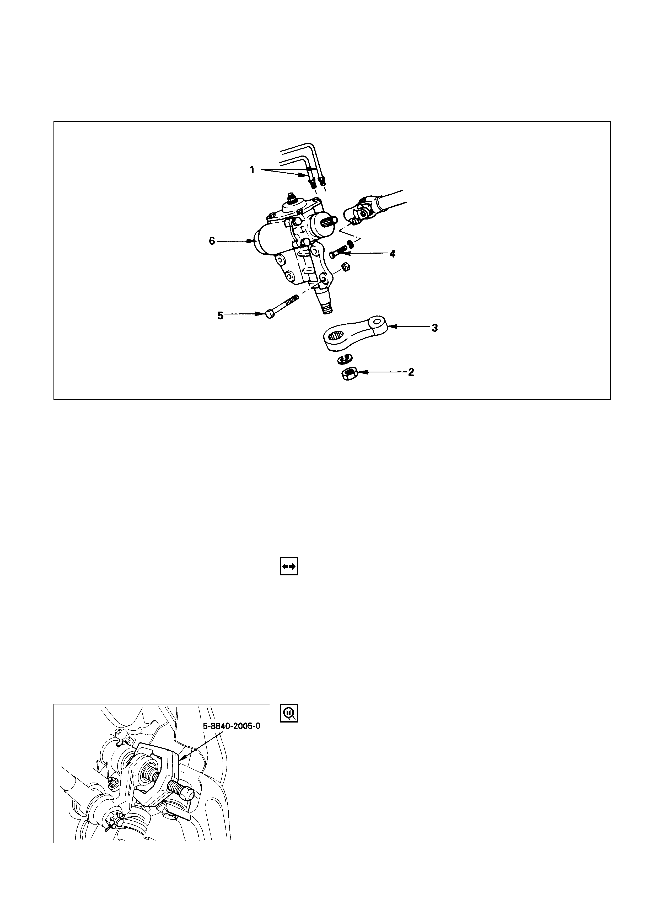
STEERING GEAR
Removal Steps
1. Pipe
2. Nut
3. Pitman arm
4. Universal joint bolt
5. Gear box mounting bolt and nut
6. Gear box
Installation Steps
6. Gear box
5. Gear box mounting bolt and nut
4. Universal joint bolt
3. Pitman arm
2. Nut
1. Pipe
REMOVAL
Preparation:
1) Remove the stone guard.
2) Remove the lower fan shroud. Refer to “Engine
cooling” in sections 6B1 and 6B.
3) Disconnect stabilizer bar at the stabilizer links.
Loosen stabilizer bracket fixing nuts.
1. Pipe
2. Nut
3. Pitman Arm
Pitman arm remover: 5-8840-2005-0 (J-29107)
These steps are based on the LHD model.
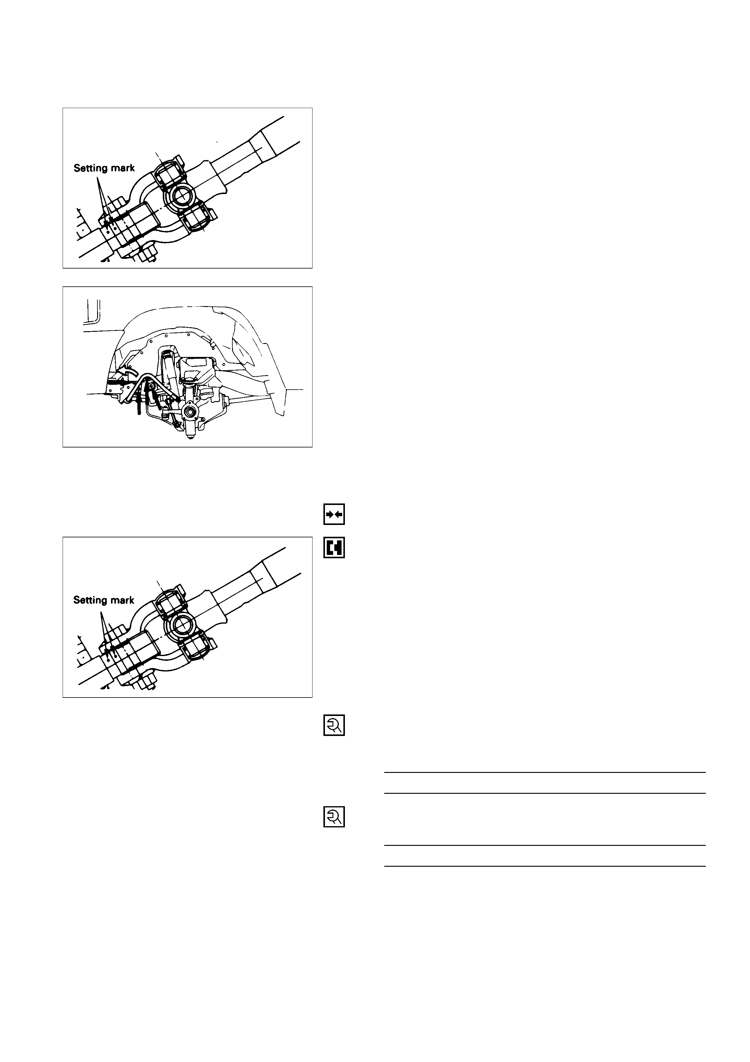
4. Universal Joint Bolt
Make a setting mark across the coupling flange and
worm shaft to ensure reassembly of the parts in the
original position.
5. Gear Box Mounting Bolt and Nut
Push the stabiliser bar aside and remove the bolts
and nuts.
6. Gear Box
INSTALLATION
6. Gear Box
Align the setting marks made at removal.
5. Gear Box Mounting Bolt and Nut
Gear Box Mounting
Bolt and Nut Torque N·m (kg·m/lb·ft)
44 (4.5 / 33)
4. Universal Joint Bolt
Coupling Clamp Bolt Torque N·m (kg·m/lb·ft)
25 (2.5 / 18)
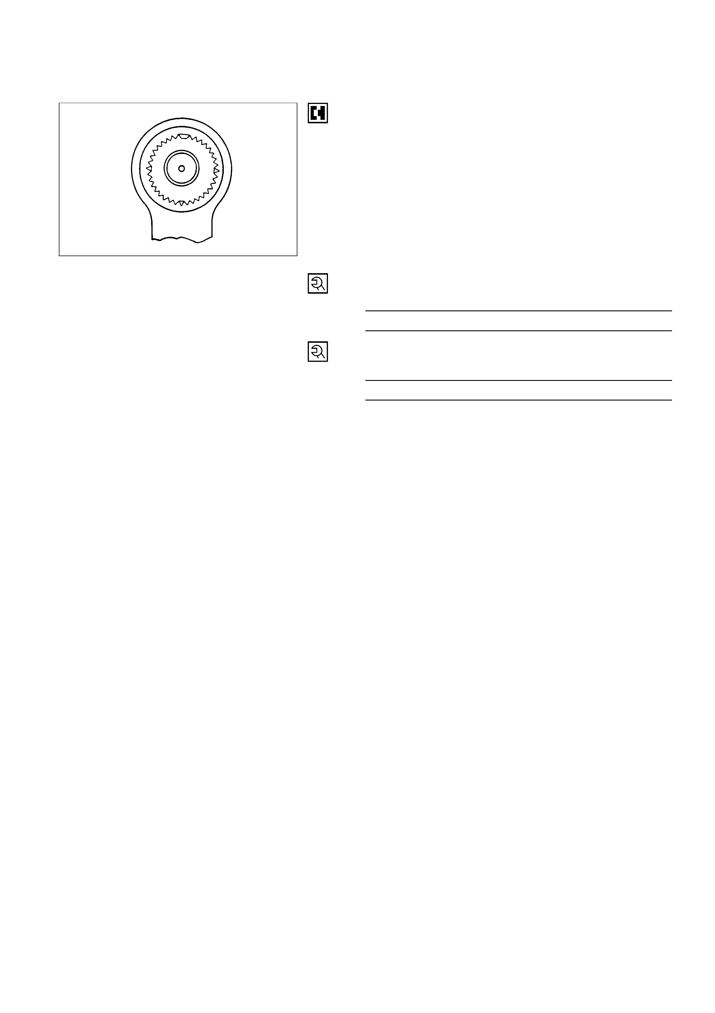
3. Pitman Arm
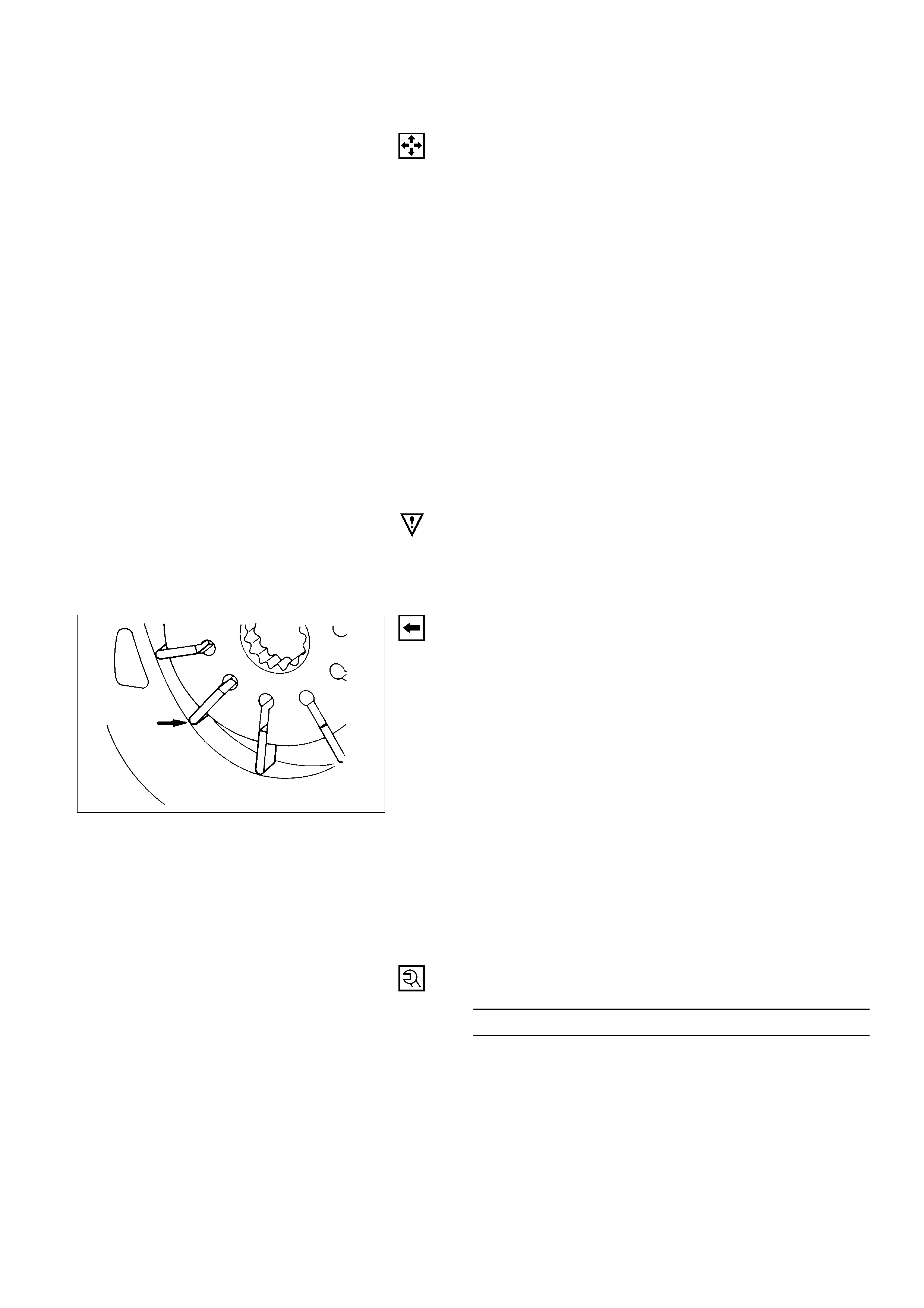
Align the notched tooth.
2 Nut
Pitman Arm Nut Torque N·m (kg·m/lb·ft)
216 (22.0 / 159)
1. Pipe
Pipe Nut Torque N·m (kg·m/lb·ft)
44 (4.5 / 33)
POWER STEERING PUMP ( 6VE1 ENGINE)
6
5
3
4
5
1
2
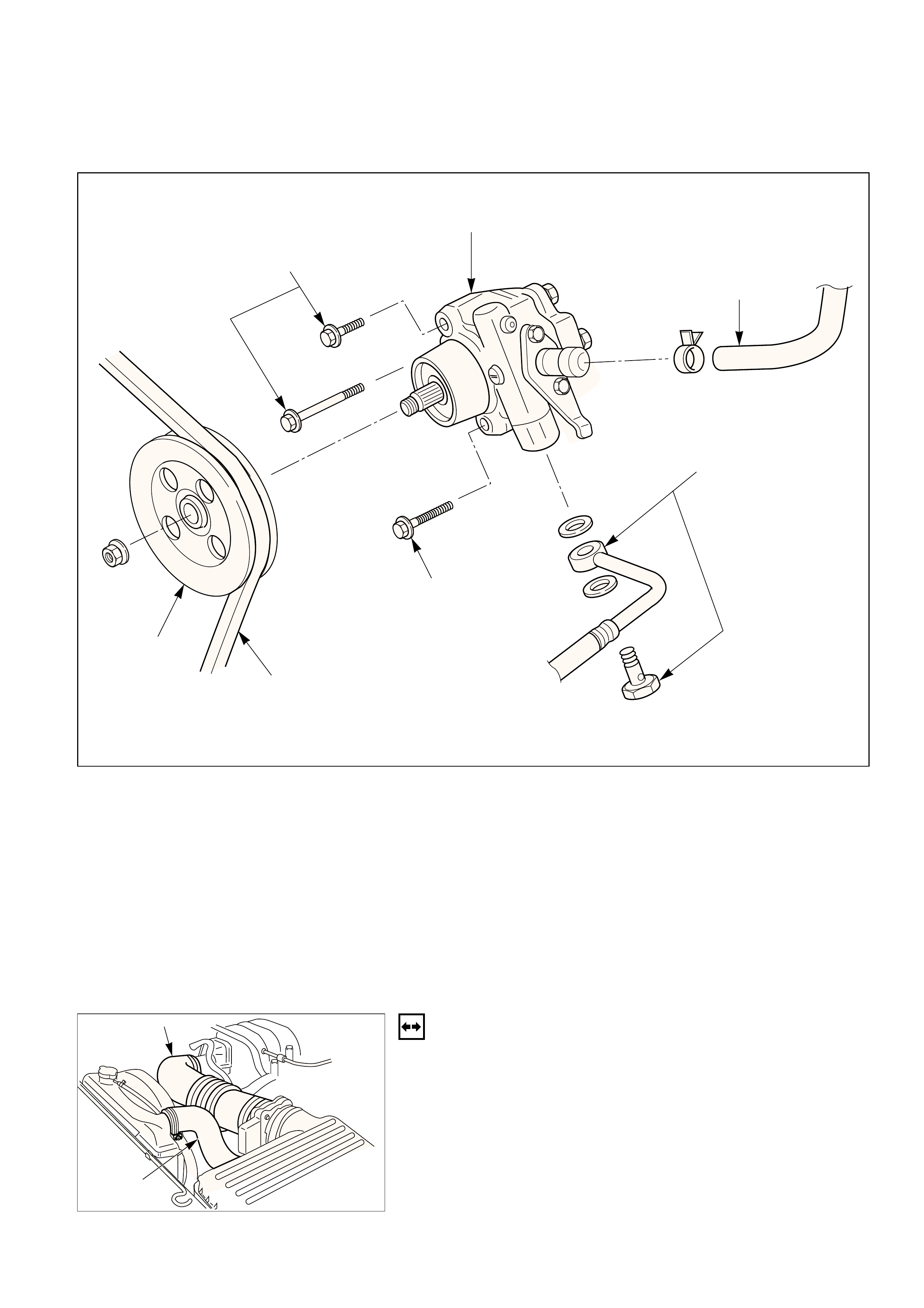
Removal Steps
1. Drive belt
2. Pulley
3. Hose, suction
4. Hose, flexible
5. Bolt
6. Pump assembly
Installation Steps
6. Pump assembly
5. Bolt
4. Hose, flexible
3. Hose, suction
2. Pulley
1. Drive belt
REMOVAL
Preparation:
•Drain the engine coolant.
•Place a drain pan below the pump.
•Remove the air cleaner duct (1) and the radiator
upper hose (2).
436RW006
1
2
436RW005
1.Drive Belt
2.Pulley
3.Hose, Suction
4.Hose, Flexible
5.Bolt
6.Pump Assembly
CAUTION:
When removing the pump assembly, be careful not to
damage the wiring harness under the pump housing.
INSTALLATION
6.Pump Assembly
Connect the harness under the pump housing.
5.Bolt
Pump Bolt TorqueN·m(kg·m/lb·ft)
46 (4.7 / 34)
4.Hose, Flexible
Eye Bolt TorqueN·m (kg·m/lb·ft)
54 (5.5 / 40)
3.Hose, Suction
2.Pulley
Install the pulley onto the power steering pump and
tighten the nut to specified torque.
Pulley Nut TorqueN·m (kg·m/lb·ft)
78 (8.0 / 58)
1.Drive Belt
•Install the air cleaner duct and the radiator upper
hose.
•Refill the engine coolant.
•Fill and bleed the system. Refer to “Bleeding the
Power Steering System” in this section.
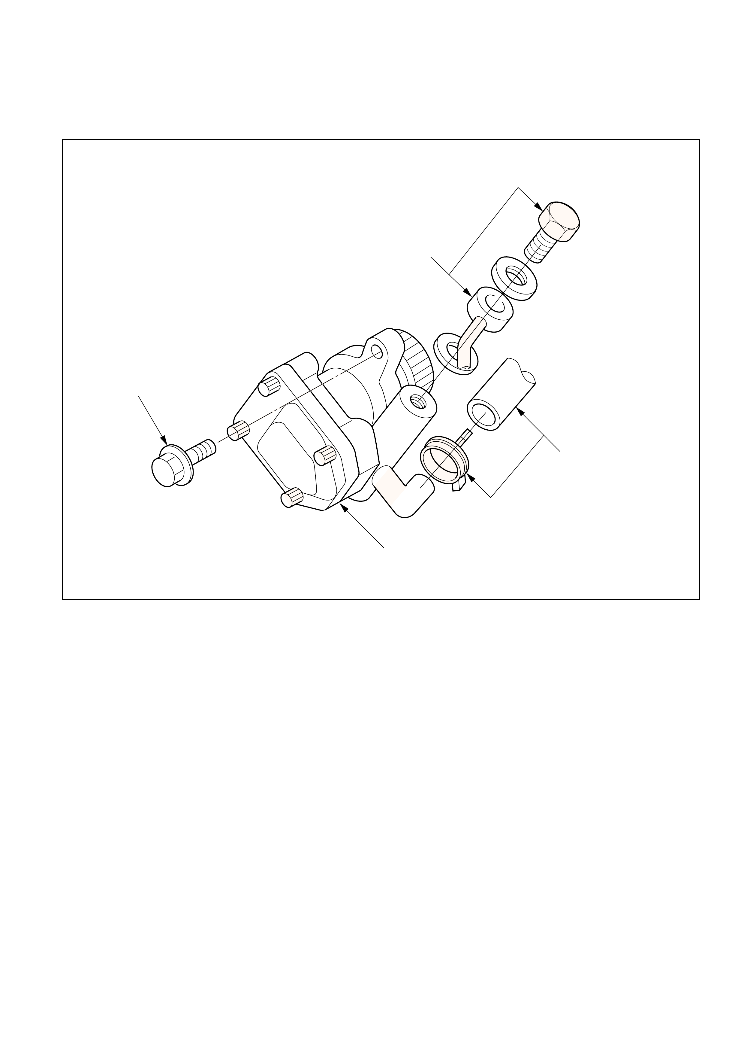
POWER STEERING PUMP (4JX1 ENGINE)
3
2
1
4
Removal Steps
1. Hose, suction
2. Hose, flexible
3. Bolt
4. Pump assembly
Installation Steps
4. Pump assembly
3. Bolt
2. Hose, flexible
1. Hose, suction
436RW009
REMOVAL
Preparation:
•Place a drain pan below the pump.
1.Hose, Suction
2.Hose, Flexible
3.Bolt
4.Pump Assembly
INSTALLATION
4.Pump Assembly
3.Bolt
Bolt TorqueN·m (kg·m/lb·ft)
22 (2.2 / 16)
2.Hose, Flexible
Hose, Bolt TorqueN·m (kg·m/lb·ft)
54 (5.5 / 40)
1.Hose, Suction
Fill and bleed the system. Refer to “Bleeding the
Power Steering System” in this section.
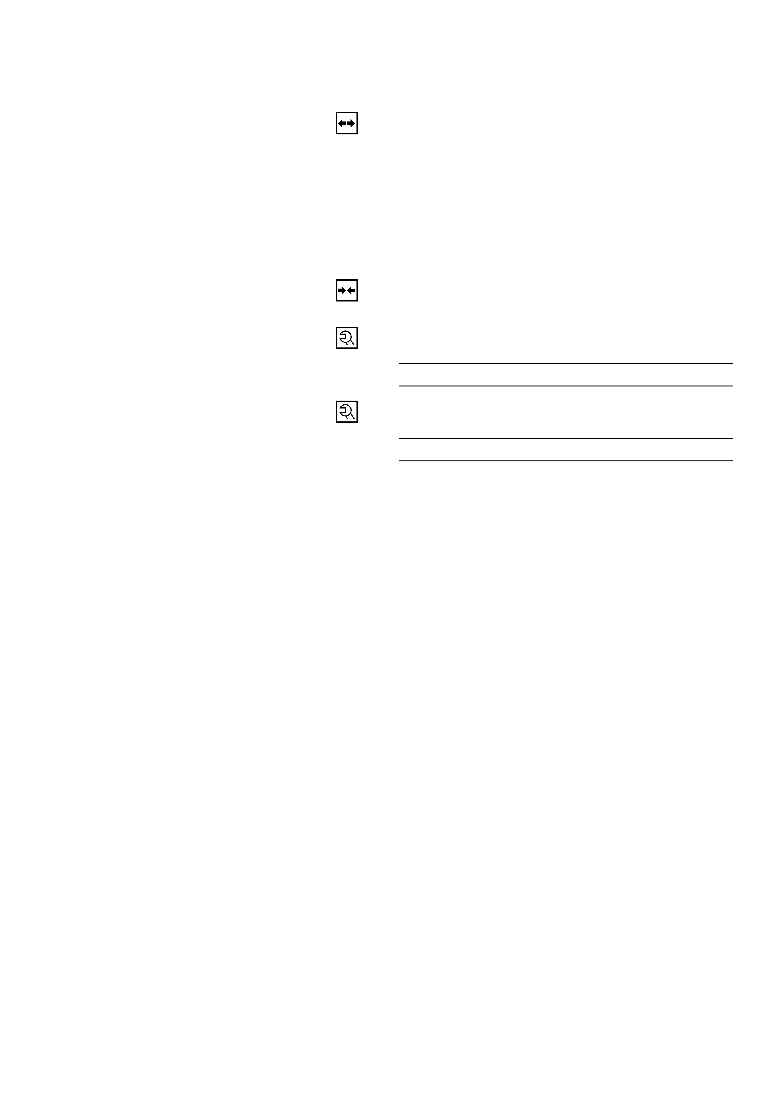
UNIT REPAIR
STEERING GEAR
5
These steps are based on the LHD model
6
8
13
1
2
3
4
9
10
11
12
7
Disassembly Steps
1. Dust cover
2. Retaining ring
3. Back up ring
4. Oil seal
5. Lock nut
6. Top cover assembly
7. O-ring
8. Sector shaft
9. Ball-nut and valve housing assembly
10. O-ring
11. Seal ring
12. O-ring
13. Gear box
Reassembly Steps
13. Gear box
12. O-ring
11. Seal ring
10. O-ring
9. Ball-nut and valve housing assembly
8. Sector shaft
7. O-ring
6. Top cover assembly
5. Lock nut
4. Oil seal
3. Back up ring
2. Retaining ring
1. Dust cover
440RW004
DISASSEMBLY
CAUTION:
Do not clamp the steering gear assembly in a vise by the
power cylinder housing.
1. Dust Cover
2. Retaining Ring
3. Back up RIng
4. Oil Seal
1) Clean the faces of the extended stub shaft.
2) Plug the hose fitting on the inlet side.
3) Remove the oil seal by blowing compressed air
through the hole in the outlet side.
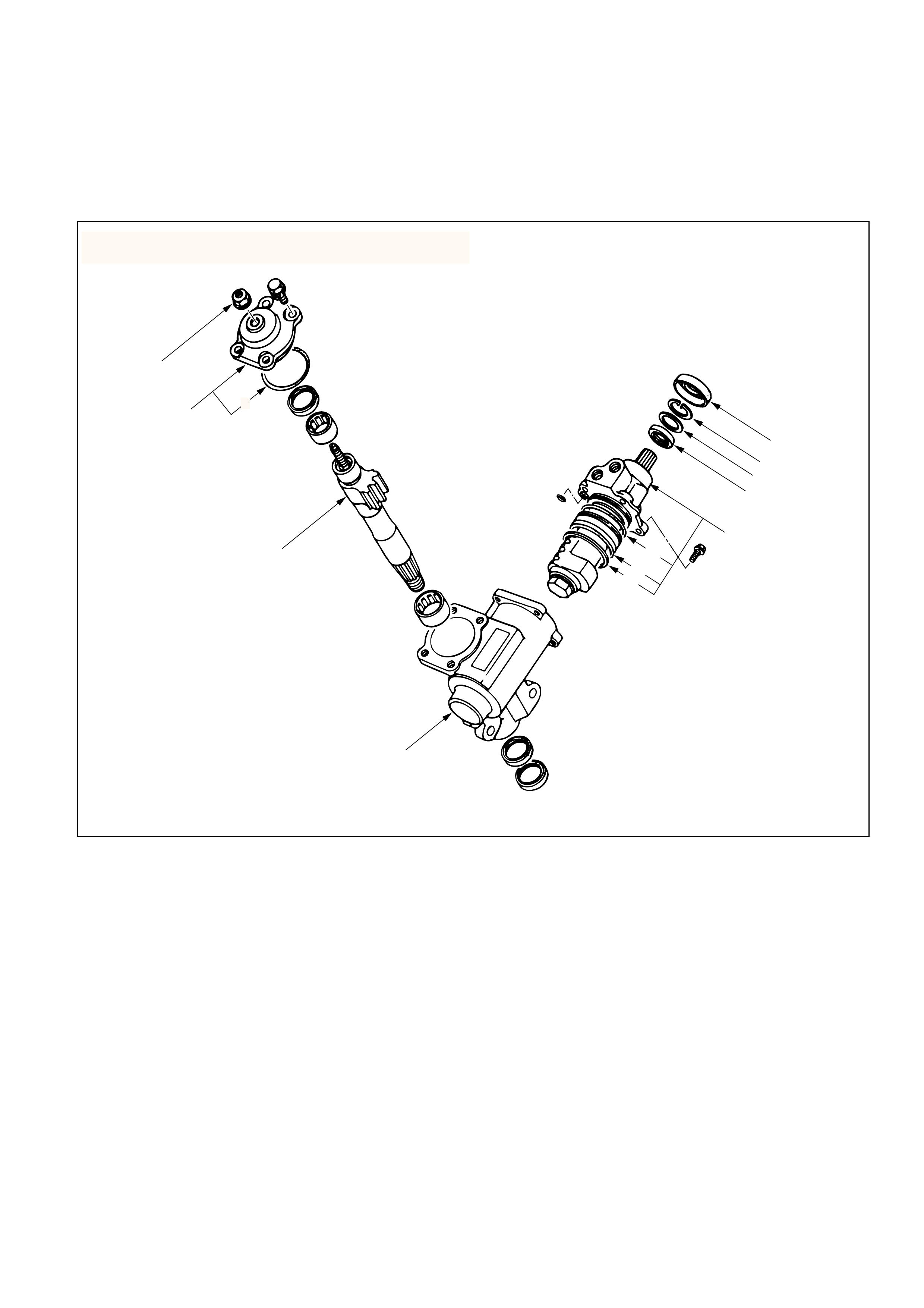
5. Lock Nut
Remove the adjusting screw lock nut and turn the
adjusting screw counterclockwise to remove the
preload between the sector gear and the rack piston,
then remove the top cover bolts.
6. Top Cover Assembly
Holding the top cover stationary, turn the adjusting
screw clockwise to raise and free to cover, then
remove the cover.
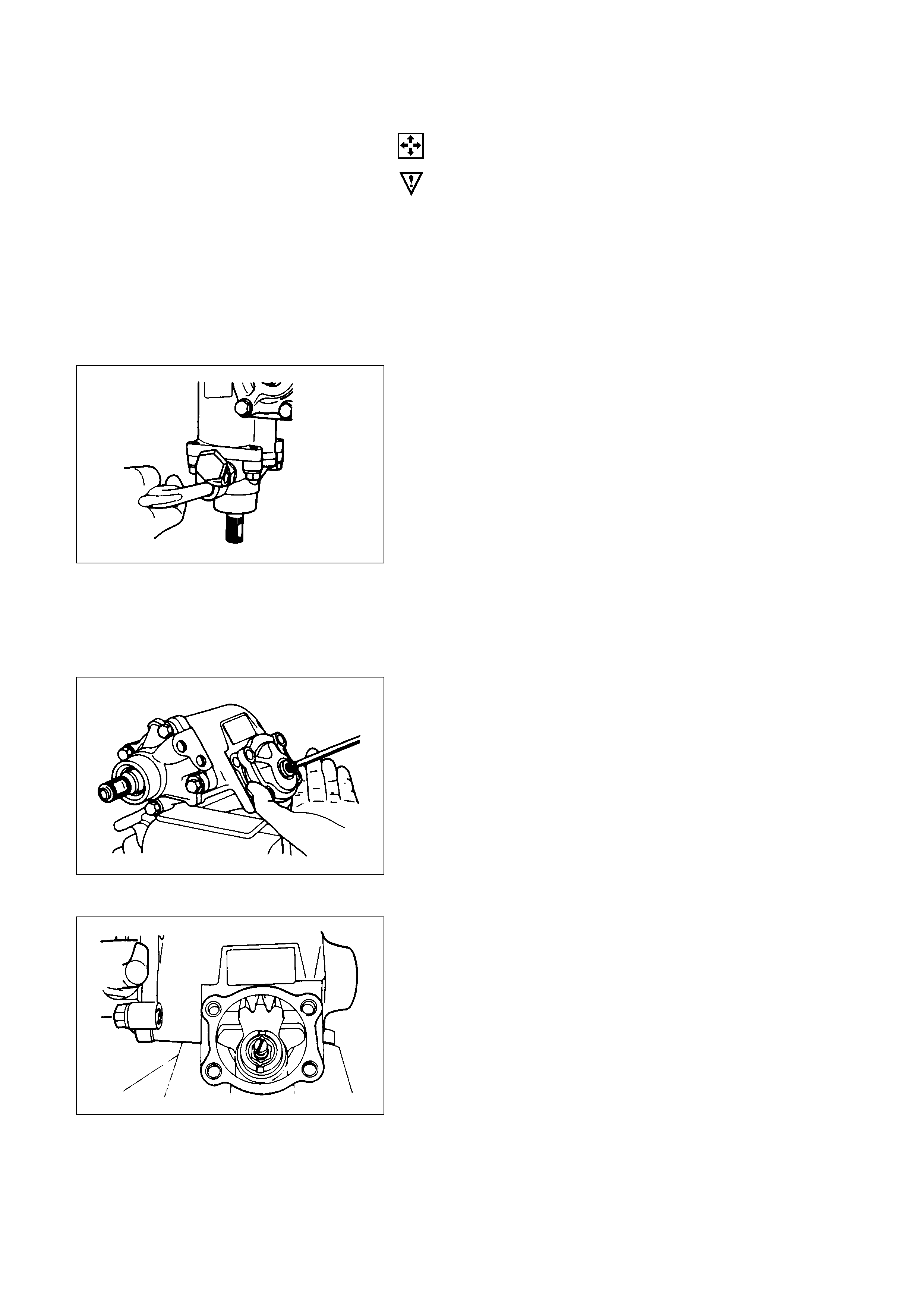
7. O-ring
8. Sector Shaft
Bring the stub shaft into straight-ahead position. Do
not force the sector shaft off the gear box with a
hammer or other impact tools.
9. Ball-nut and Valve Housing Assembly
It is strongly advisable to always keep the ball nut
and valve housing assembly in a horizontal position,
or the rack piston will fall off onto the end of the
worm, causing the rack piston to slip out of the worm
shaft and the balls to fall out.
10. O-ring
11. Seal Ring
12. O-ring
13. Gear Box
INSPECTION AND REPAIR
Inspect the following parts for wear, damage or any other
abnormal conditions.
•Bearing
•Ball-nut and valve housing
•Sector shaft
•Top cover
•Gear box
•Needle bearing
•Dust seal
•Seal ring
•Gasket
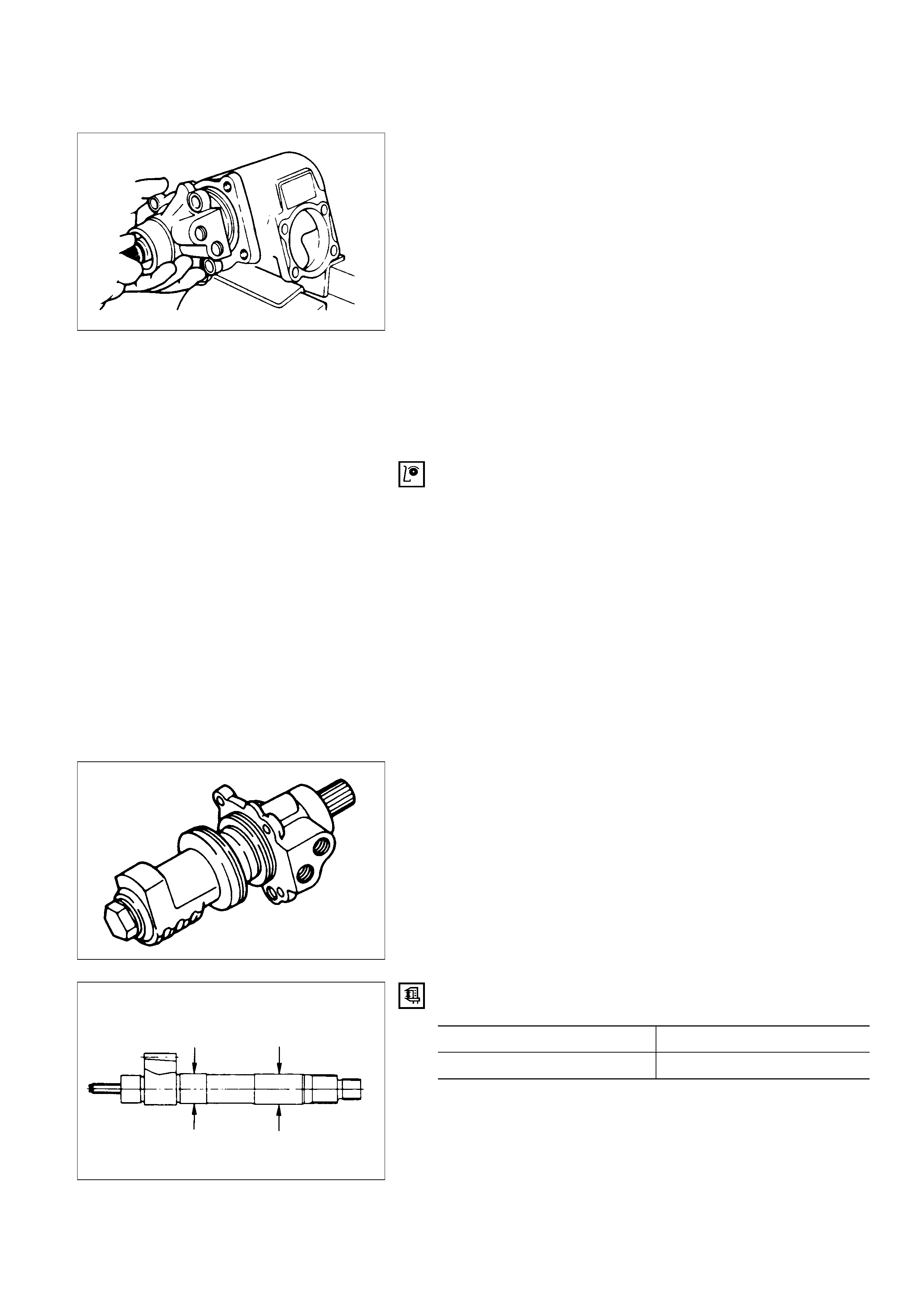
Ball-nut Rotation
Hold the ball nut and valve housing assembly vertically
and see if the ball-nut lower by turning smoothly. If the
ball-nut does not lower smoothly, check the worm shaft
for bending and foreign matter.
NOTE:
When testing the ball nut and valve housing assembly, do
not let it travel all the way to the end of worm shaft, or
damage to the ball tubes will result.
Check sector shaft outside diameter.
Sector Shaft Outside Diameter mm(in)
Standard Limit
32.0 (1.260) 31.7 (1.248)
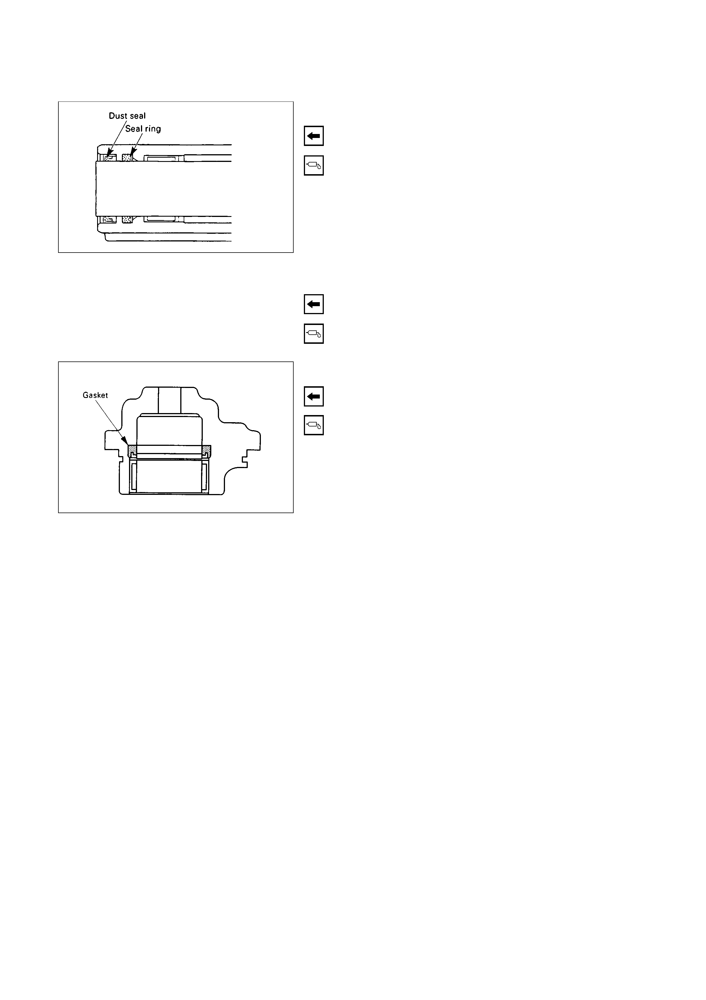
Seal Ring Setting
Note the setting direction. Always install a new part.
Apply a thin coat of power steering fluid to lip of each
part.
Dust Seal Setting
Note the setting direction. Always install a new part.
Apply a thin coat of power steering fluid to lip of each
part.
Gasket Setting
Note the setting direction. Always install a new part.
Apply a thin coat of power steering fluid to lip of each
part.
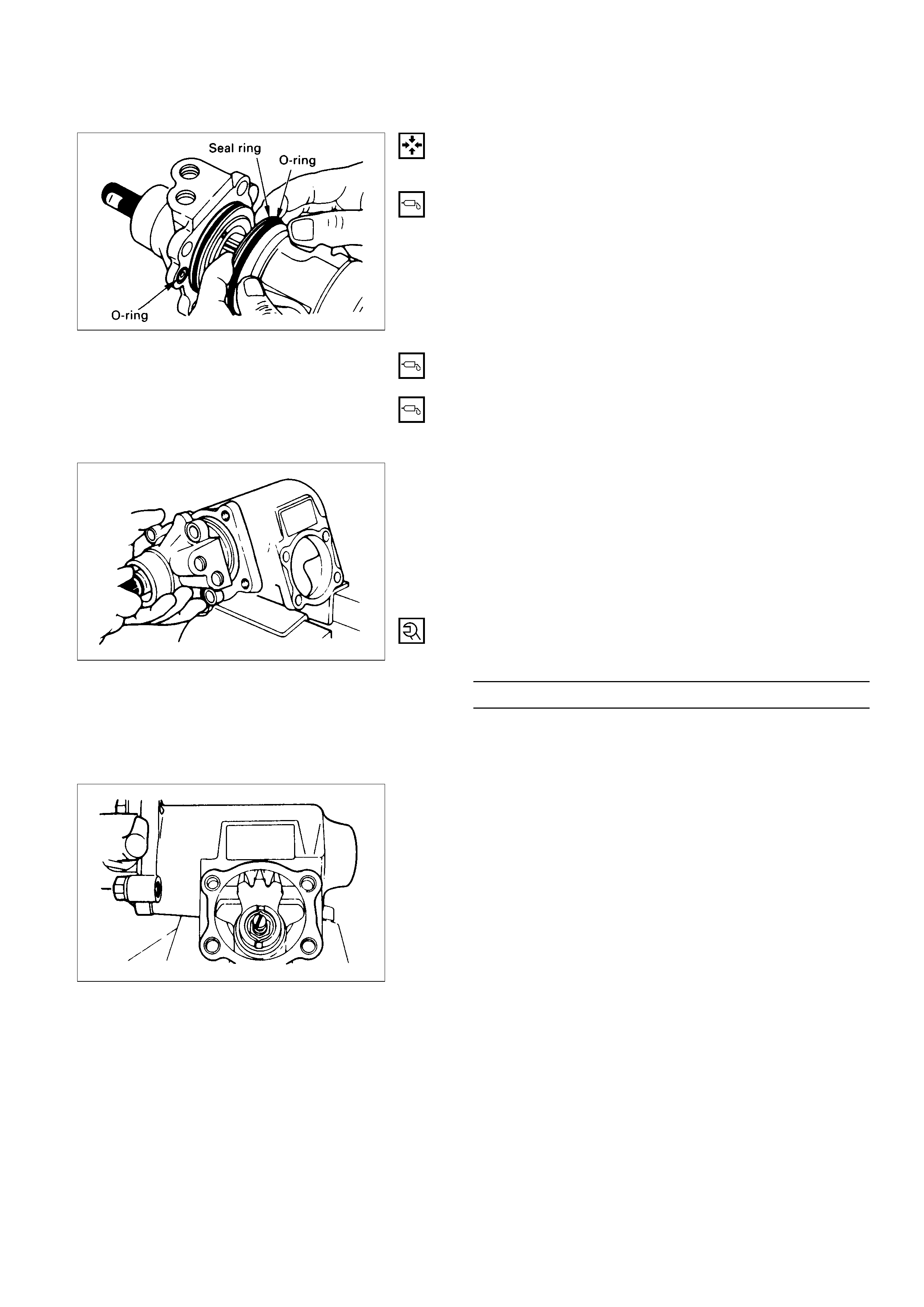
REASSEMBLY
13. Gear Box
12. O-ring
Apply a thin coat of grease.
11. Seal Ring
Apply a thin coat of grease.
10. O-ring
Apply a thin coat of grease.
9. Ball-nut and Valve Housing Assembly
1) It is strongly advisable to always keep the ball
screw and valve housing assembly in a horizontal
position (avoid holding it vertically), or the rack
piston will fall off onto the end of the worm,
causing the rack piston to slip out of the worm
shaft and ball to fall out.
2) Be careful not to drop the O-ring into the valve
housing.
3) Tighten the valve housing bolts to the specified
torque.
Valve Housing Bolt Torque N·m (kg·m/lb·ft)
47 (4.8 / 35)
8. Sector Shaft
1) Tape the sector shaft serrations to protect the
seal ring from damage.
2) Align the center tooth of ball nut with that of the
sector shaft.
7. O-ring
6. Top Cover Assembly
Top Cover Bolt Torque N·m (kg·m/lb·ft)
47 (4.8 / 35)
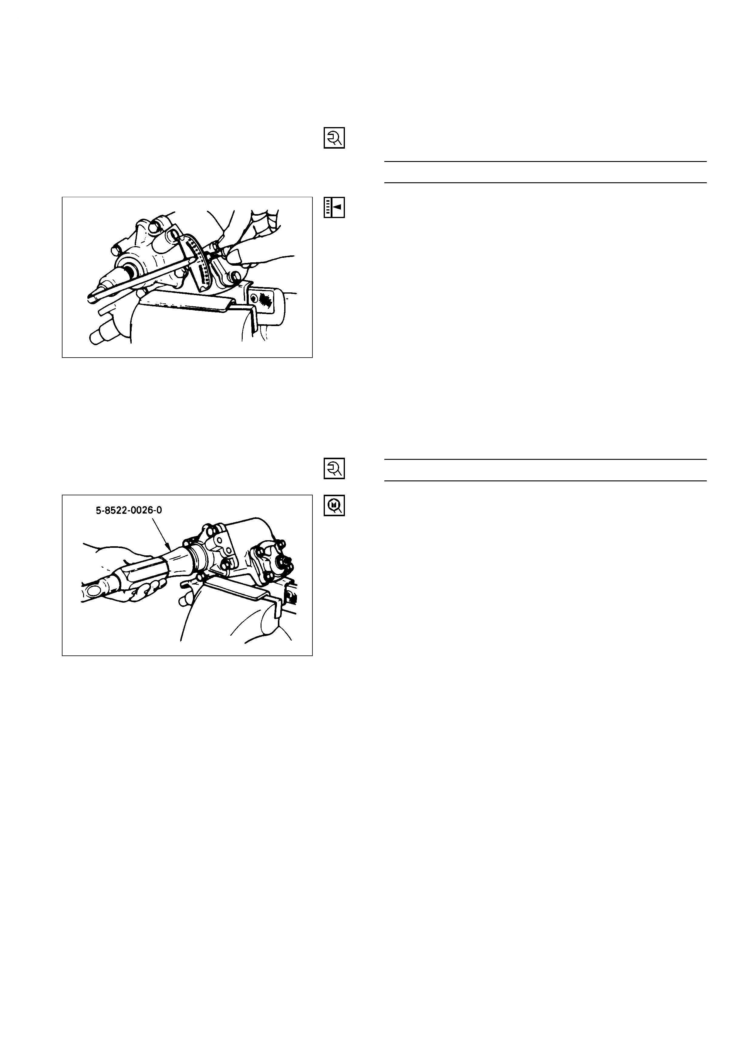
5. Lock Nut
Adjust the backlash between the worm gear and the
ball nut.
1) With the worm gear rotating, set it to the straight
ahead position.
2) Set the worm shaft preload to below 1N·m
(10kg·cm / 9 lb·in) with the sector shaft adjusting
screw.
3) Measure the worm shaft preload with the worm
gear turned 450° both to the right and to the left.
The worm gear preload in these positions should
be 0.4 - 0.6 N·m (4 - 6 kg·cm / 3.5 - 5.2 lb·in) lower
than in the straight ahead position.
4) Lock the sector shaft adjusting screw with the lock
nut.
Lock Nut Torque N·m (kg·m/lb·ft)
41 (4.2 / 30)
4. Oil Seal
Installer: 5-8522-0026-0 (J-26508)
3. Back up Ring
Position the chamfered face (outer circumference)
towards the oil seal.
2. Retaining Ring
position the chamfered face (outer circumference)
toward the oil seal.
1. Dust Cover
POWER STEERING PUMP ( 6VE1 ENGINE)
2
3
22
1
16
15
12
11
5
6
8
7
9
4
17
18
27
25
26
24
19
20
23
21
14
13
10
Disassembly Steps
1. Bolt
2. Pipe, suction
3. O-ring
4. Connector
5. O-ring
6. Valve
7. Retaining ring
8. Filter
9. Spring
10. Pressure switch
11. Retaining ring
12. Shaft assembly
13. Bearing
14. Shaft
15. Retaining ring
16. Oil seal
17. Bolt
18. Rear housing assembly and pump
cartridge
19. Gasket
20. O-ring
21. O-ring
22. Front housing
23. Pressure plate
24. Rotor and vane
25. Cam
26. Pin
27. Rear housing
Reassembly Steps
27. Rear housing
26. Pin
25. Cam
24. Rotor and vane
23. Pressure plate
22. Front housing
21. O-ring
20. O-ring
19. Gasket
18. Rear housing assembly and pump
cartridge
17. Bolt
16. Oil seal
15. Retaining ring
14. Shaft
13. Bearing
12. Shaft assembly
11. Retaining ring
10. Pressure switch
9. Spring
8. Filter
7. Retaining ring
6. Valve
5. O-ring
4. Connector
3. O-ring
2. Pipe, suction
1. Bolt
412RW055
DISASSEMBLY
Preparation:
Clean oil pump with solvent (plug the discharge and
suction port, to prevent the entry of solvent). Be careful
not to expose the oil seal of shaft assembly to solvent.
1.Bolt
2.Pipe, Suction
3.O-ring
4.Connector
5.O-ring
6.Valve Assembly
7.Retaining Ring
8.Filter
9.Spring
10.Pressure switch
11.Retaining Ring
12.Shaft Assembly
13.Bearing
14.Shaft
15.Retaining Ring
16.Oil Seal
CAUTION:
When removing the oil seal, be careful not to damage the
housing.
17. Bolt
18. Rear Housing Assembly and Pump Cartridge
19. Gasket
20. O-ring
21. O-ring
22. Front Housing
23. Pressure Plate
24. Rotor and Vane
25. Cam
26. Pin
27. Rear Housing
INSPECTION AND REPAIR
Make all necessary adjustments, repairs, and part
replacements if wear, damage, or other problems are
discovered during inspection.
Rotor
Check that the groove in the vane is free from excessive
wear and that the vane slides smoothly.
When part replacement becomes necessary, the pump
cartridge should be replaced as a subassembly.
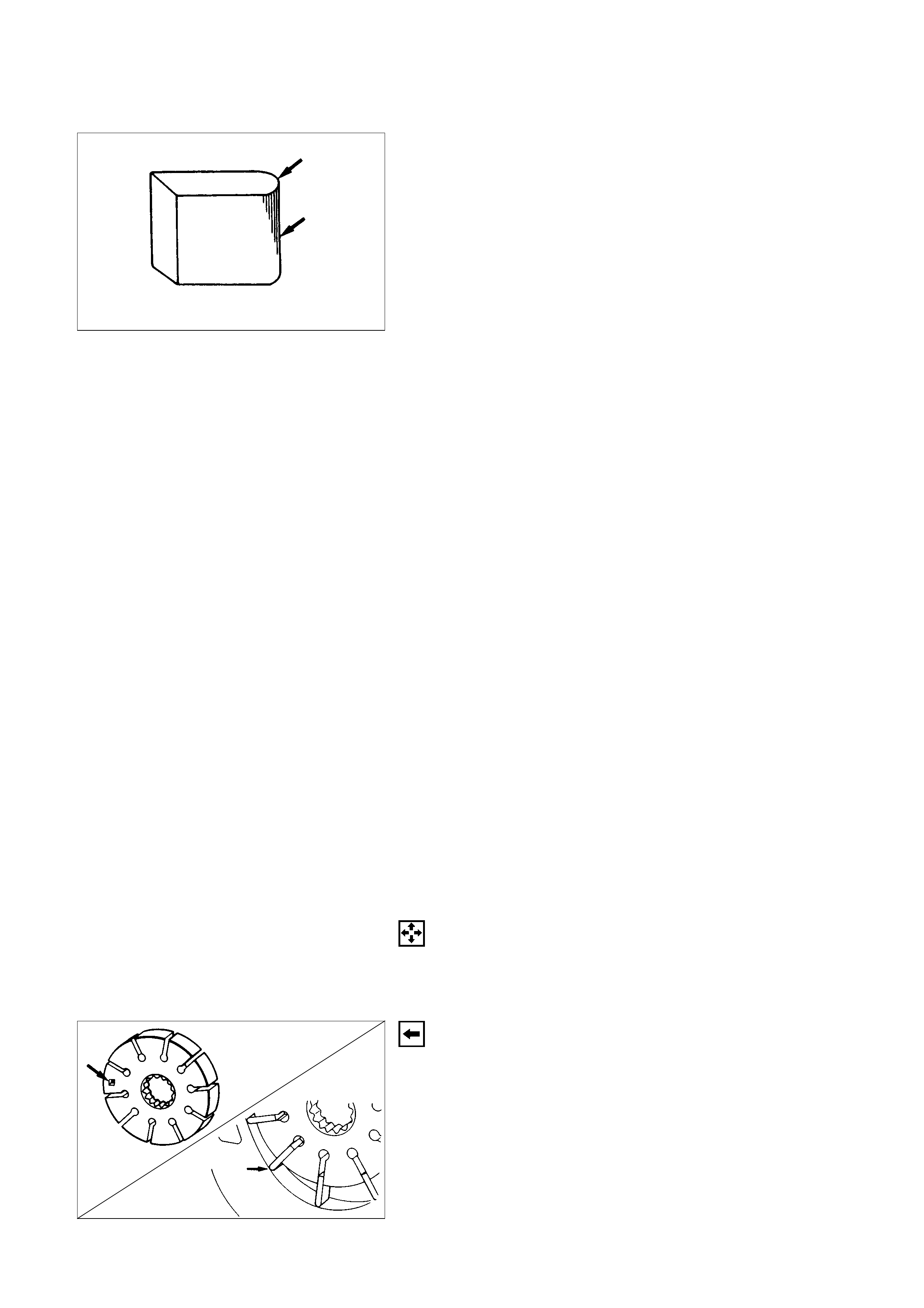
Vane
Sliding faces of the vane should be free from wear.
(Particularly the curved face at the tip in contact with the
cam should be free from wear and distortion).
When part replacement becomes necessary, the pump
cartridge should be replaced as a subassembly.
Cam
The inner face of the arm should have a uniform contact
pattern without a sign of step wear.
When part replacement becomes necessary, the pump
cartridge should be replaced as a subassembly.
Side plate
The sliding faces of parts must be free from step wear
(more than 0.01 mm), which can be felt by the finger nail.
The parts with minor scores may be reused after lapping
the face.
Valve
The sliding face of the valve must be free from burrs and
damage.
The parts with minor scores may be reused after
smoothing with emery cloth (#800 or finer).
Shaft
Oil seal sliding faces must be free from a step wear which
can be felt by the finger nail.
Bushing face must be free from damage and wear.
O-ring, oil seal, retaining ring
Be sure to discard used parts, and always use new parts
for installation. Prior to installation, lubricate all seals and
rings with power steering fluid.
REASSEMBLY
27. Rear Housing
26. Pin
25. Cam
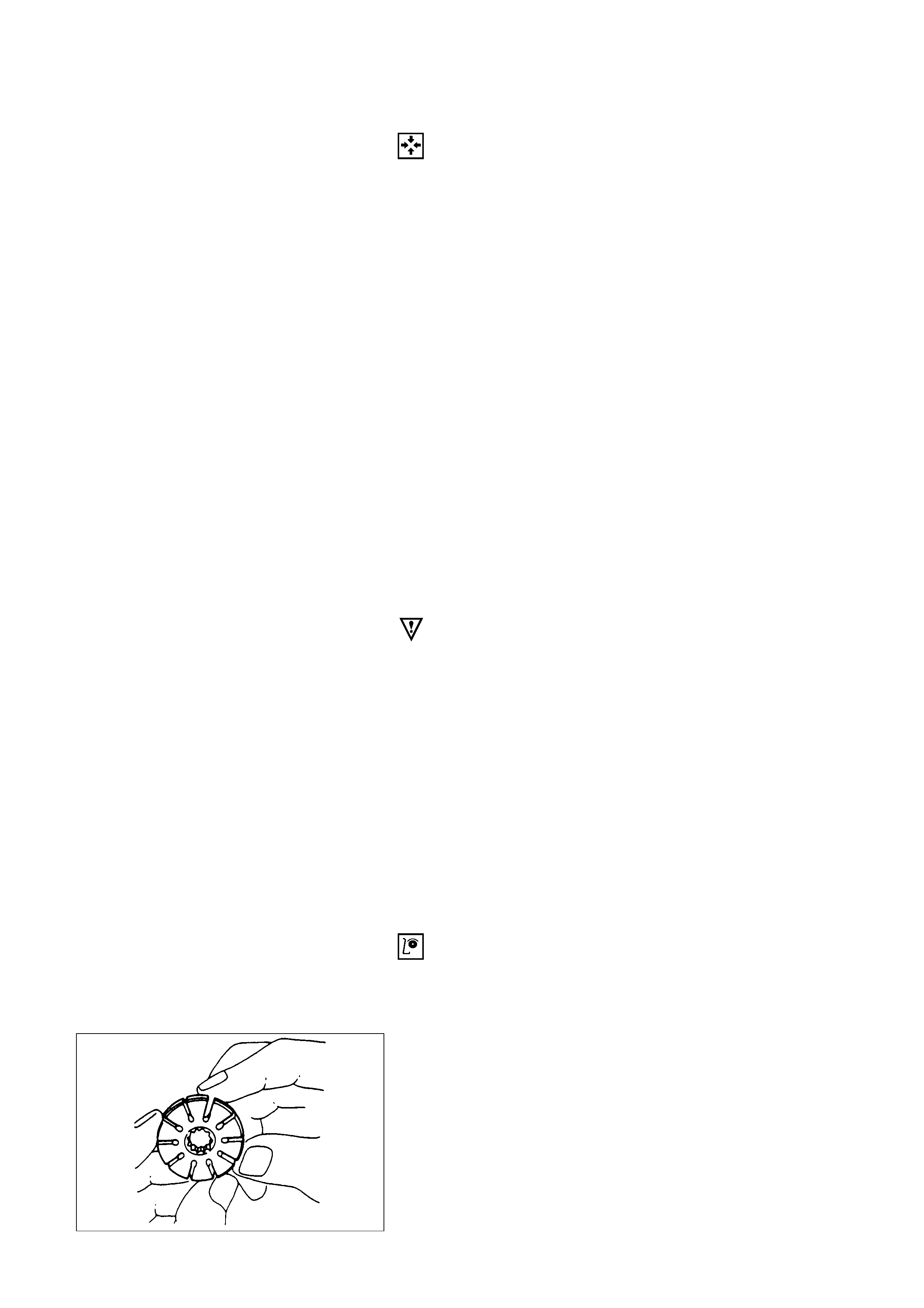
24. Rotor and Vane
1. Install the rotor with its punch mark facing the front
housing.
2. Install the vanes with curved face in contact with
the inner wall of the cam.
23.Pressure Plate
CAUTION:
When installing side plate, be careful not to damage its
inner surface. Damaged side plate may cause poor pump
performance, pump seizure or oil leakage.
22.Front Housing
21.O-ring
20.O-ring
Be sure to discard used O-rings, and always use new
parts for installation.
19.Gasket
Be sure to discard used parts, and always use new
parts for installation.
18.Rear Housing Assembly and Pump Cartridge
17.Bolt
Rear Housing Bolt TorqueN·m (kg·m/lb·ft)
17.6 (1.8 / 12.8)
16.Oil Seal
Be sure to discard used parts, and always use new
parts for installation.
CAUTION:
When installing the oil seal, be careful not to damage the
oil seal contacting surface of the housing.
15. Retaining Ring
14. Shaft
13. Bearing
12. Shaft Assembly
11. Retaining Ring
10. Pressure switch
Pressure Switch Torque N·m (kg·m/lb·ft)
20 (2.0 / 14)
9. Spring
8. Filter
7. Retaining Ring
6. Valve
5. O-ring
Be sure to discard used parts, and always use new
parts for installation.
4. Connector
Connector Torque N·m (kg·m/lb·ft)
74 (7.5 / 54)
3. O-ring
Be sure to discard used parts, and always use new
parts for installation.
2. Pipe, Suction
1. Bolt
Suction Pipe Bolt Torque N·m (kg·m/lb·ft)
15.7 (1.6 / 11.5)
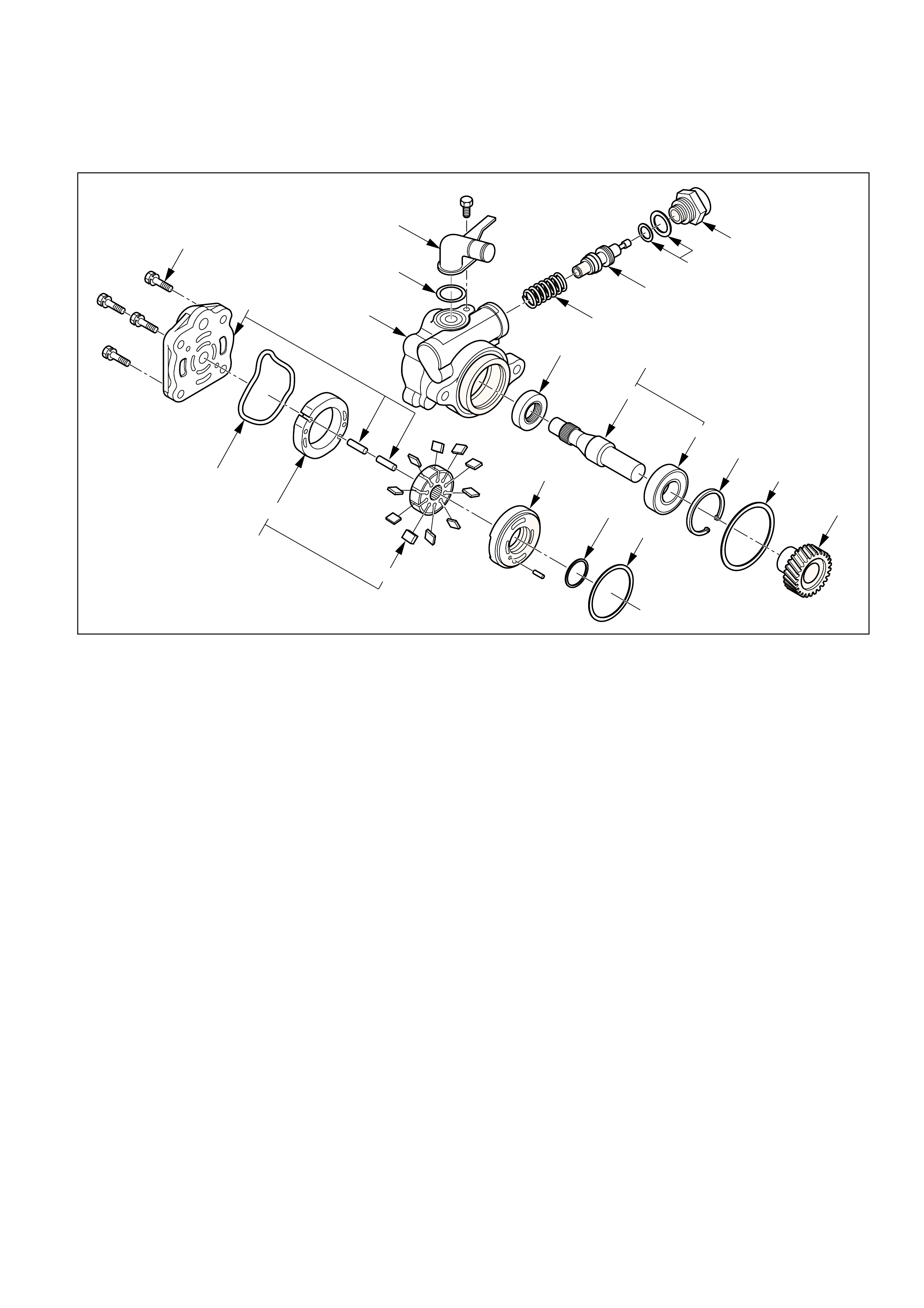
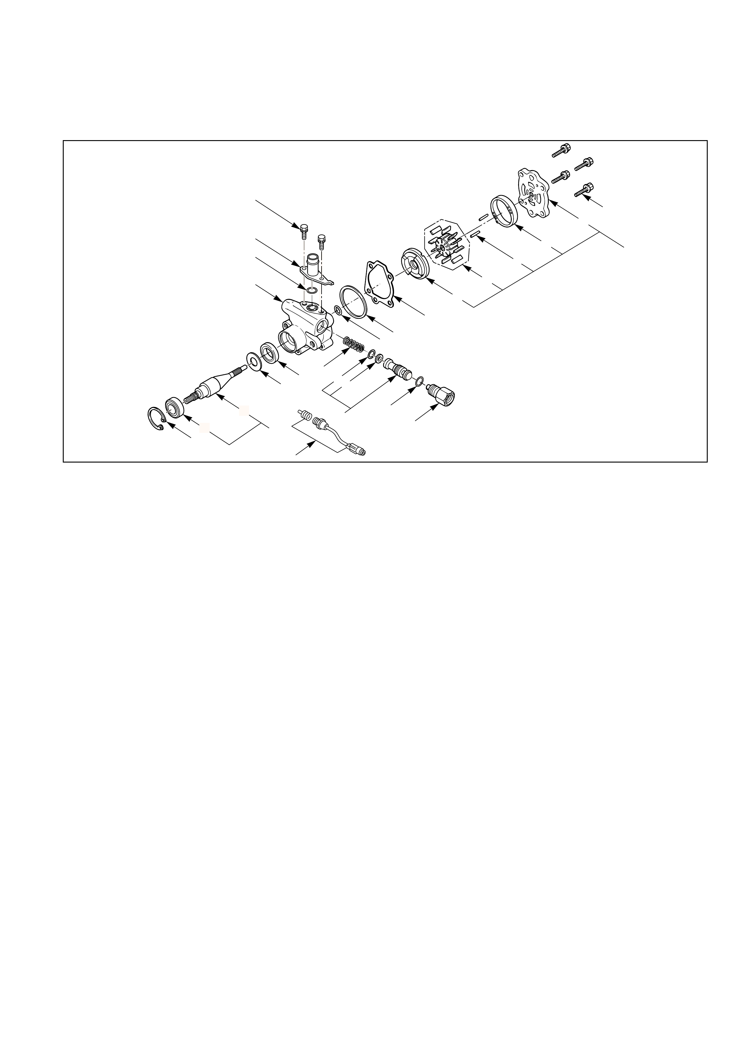
POWER STEERING PUMP (4JX1 ENGINE)
17
1
18
22
7
6
5
4
3
2
19
20
21
15
14
16
8
10
12
11
13
923
Disassembly Steps
1. O-ring
2. Pipe, suction
3. O-ring
4. Connector
5. O-ring
6. Valve
7. Spring
8. Bolt
9. Rear housing assembly
10. O-ring
11. Pump cartridge
12. Cam
13. Rotor and vane
14. Pressure plate
15. O-ring
16. O-ring
17. Gear
18. Retaining ring
19. Shaft assembly
20. Bearing
21. Shaft
22. Oil seal
23. Front housing
Reassembly Steps
23. Front housing
22. Oil seal
21. Shaft
20. Bearing
19. Shaft assembly
18. Retaining ring
17. Gear
16. O-ring
15. O-ring
14. Pressure plate
13. Rotor and vane
12. Cam
11. Pump cartridge
10. O-ring
9. Rear housing assembly
8. Bolt
7. Spring
6. Valve
5. O-ring
4. Connector
3. O-ring
2. Pipe, suction
1. O-ring
412RW048

DISASSEMBLY
Preparation:
Clean oil pump with solvent (plug the discharge and
suction port to prevent the entry of solvent). Be careful not
to expose the oil seal of shaft assembly to solvent.
1.O-ring
2.Pipe, Suction
3.O-ring
4.Connector
5.O-ring
6.Valve
7.Spring
8.Bolt
9.Rear Housing Assembly
10.O-ring
11.Pump Cartridge
12.Cam
13.Rotor and Vane
14.Pressure Plate
15.O-ring
16.O-ring
17.Gear
18.Retaining Ring
19.Shaft Assembly
20.Bearing
21.Shaft
22.Oil seal
CAUTION:
When removing the oil seal, be careful not to damage the
housing.
23. Front Housing
REASSEMBLY
23.Front Housing
22.Oil Seal
Be sure to discard used parts, and always used new
parts for installation.
21.Shaft
20.Bearing
19.Shaft Assembly
18.Retaining Ring
17.Gear
16.O-ring
Be sure to discard used parts, and always used new
parts for installation.
15.O-ring
Be sure to discard used parts, and always used new
parts for installation.
14.Pressure Plate
CAUTION:
When install pressure plate, be careful not to damage its
inner surface. Damaged pressure plate may cause poor
pump performance, pump seizure or oil leakage.
13. Rotor and Vane
Install the vane with curved face in contact with the
inner wall of the cam.
12. Cam
11. Pump Cartridge
10. O-ring
Be sure to discard used parts, and always used new
parts for installation.
9. Rear Housing Assembly
8. Bolt
Rear Housing Bolt Torque N·m (kg·m/lb·ft)
24 (2.4 / 17)
7. Spring
6. Valve
5. O-ring
Be sure to discard used parts, and always used new
parts for installation.
4. Connector
Connector Torque N·m (kg·m/lb·ft)
59 (6.0 / 43)
3. O-ring
Be sure to discard used parts, and always used new
parts for installation.
2. Pipe, Suction
Suction Pipe Bolt Torque N·m (kg·m/lb·ft)
9.8 (1.0 / 7.1)
1. O-ring
Be sure to discard used parts, and always used new
parts for installation.