
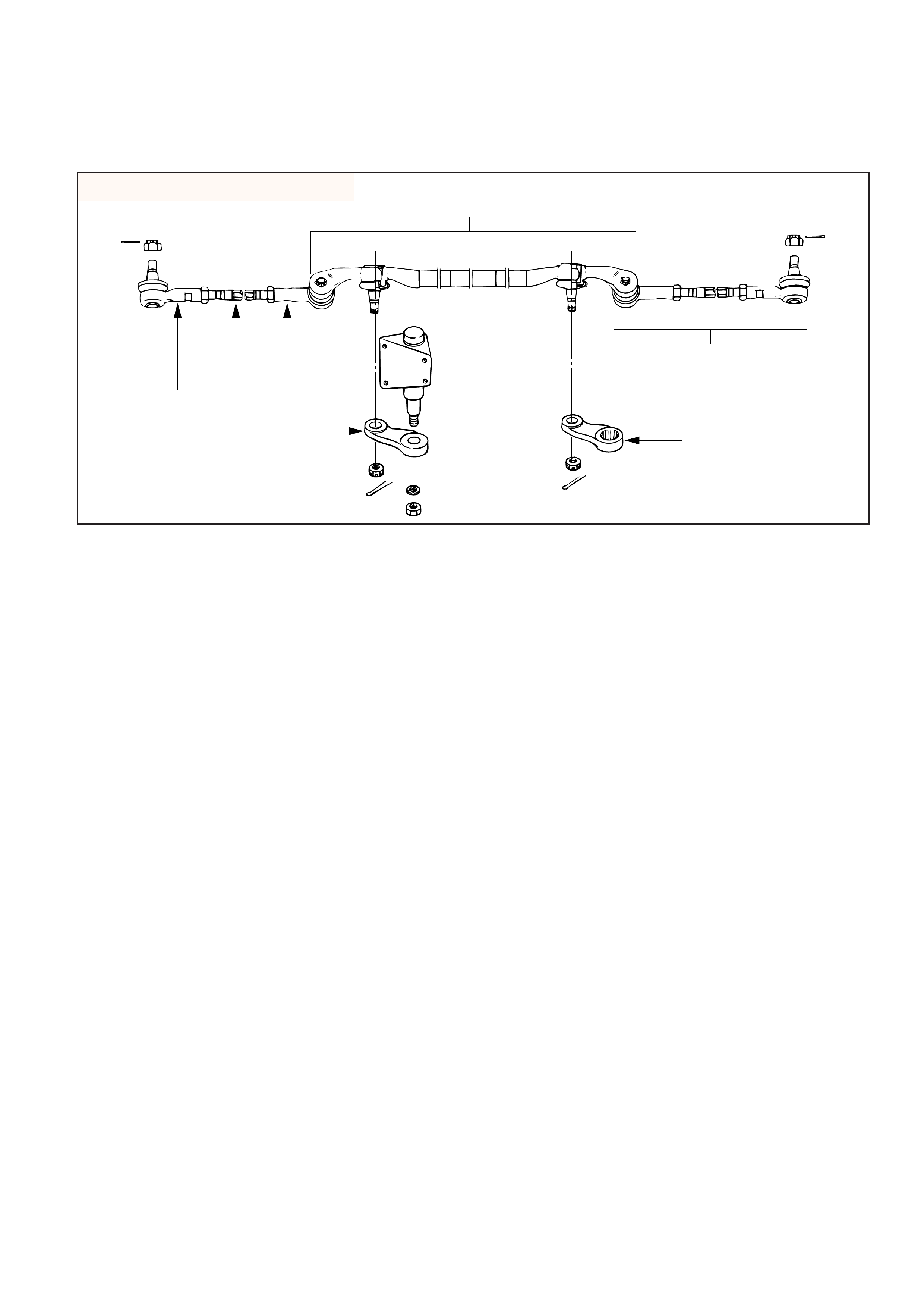
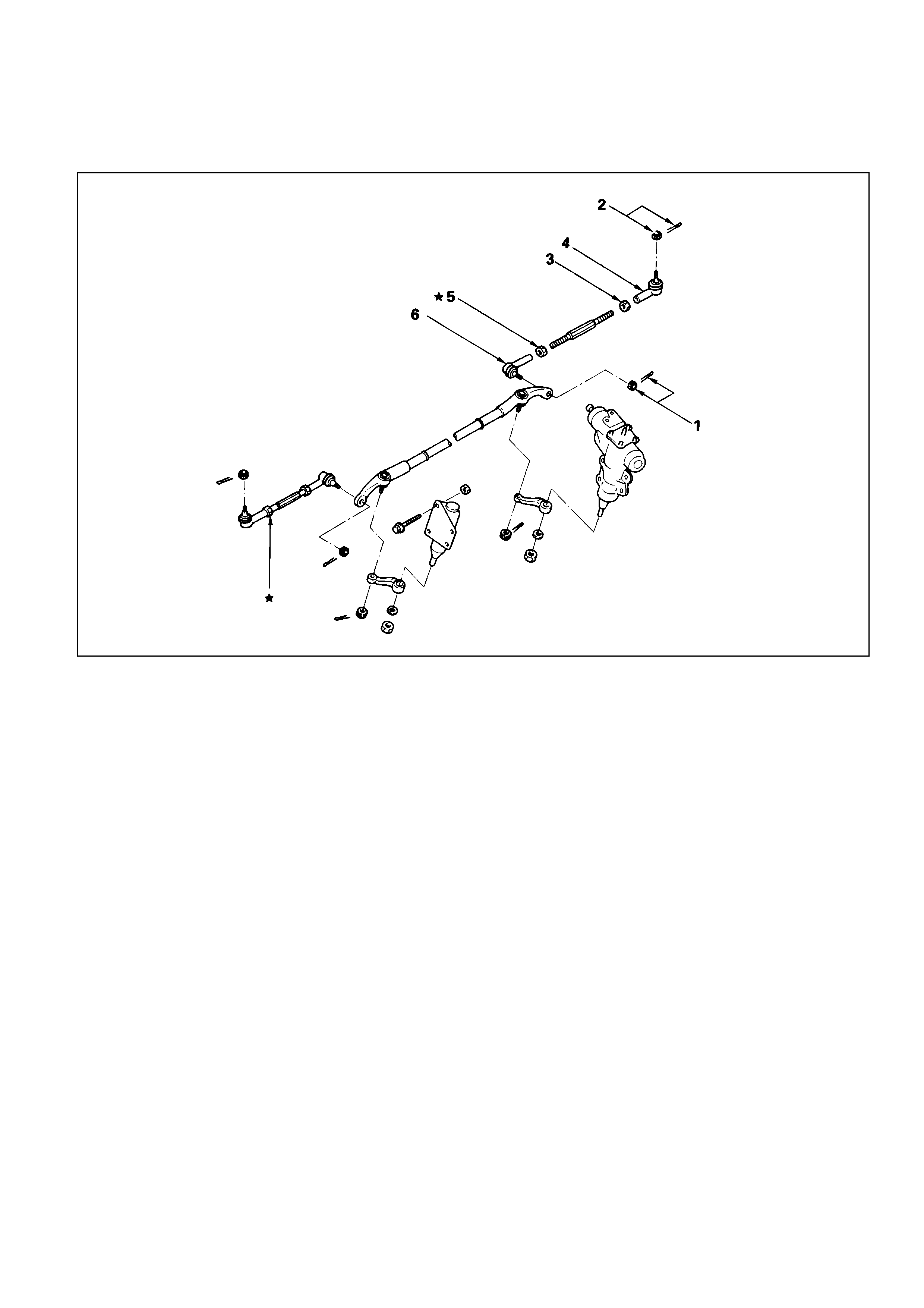
GENERAL DESCRIPTION
Center track rod assembly
Rod end, outer
Track rod
Rod end, inner
Relay lever
These steps are based on the LHD model.
Outer track rod assembly
Pitman arm
The steering linkage consists of a pitman arm,
relay lever, center track rod and two adjustable
outer track rods.
When the steering wheel is turned, the gear rotates
the pitman arm which forces the center track rod to
one side. The outer track rods, connected to the
center track rod by ball studs, transfer the steering
force to the wheels. The outer track rods are
adjustable and are used for toe-in adjustments.
The center track rod is supported by the pitman
arm and relay lever. The relaylever pivots on a
support attached to the frame.
The overall condition of the steering linkage affects
steering performance. If parts are bent, damaged,
worn or poorly lubricated, improper and possibly
dangerous steering action will result.
Whenever any steering linkage components are
repaired or replaced, check the steering geometry
and front end alignment. Refer to Front End
Alignment (Sec. 3A).
433RW004
This illustration is based on the LHD model.
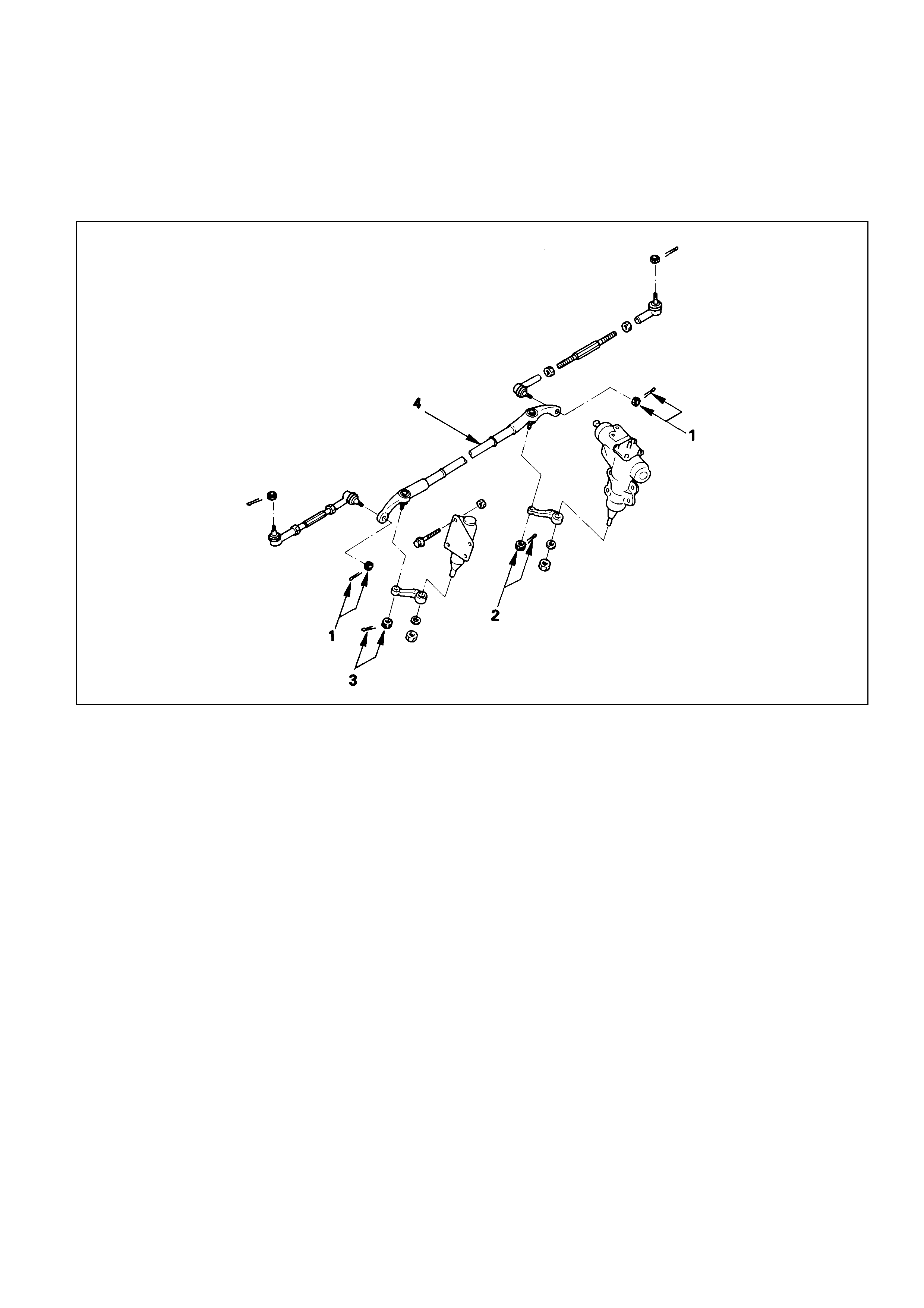
ON-VEHICLE SERVICE
CENTRE TRACK ROD ASSEMBLY
Removal Steps
1. Nut and cotter pin
2. Nut and cotter pin, pitman arm
3. Nut and cotter pin relay lever
4. Center track rod assembly
Installation Steps
4. Center track rod assembly
3. Nut and cotter pin relay lever
2. Nut and cotter pin, pitman arm
1. Nut and cotter pin
REMOVAL
Preparation:
Raise the vehicle and support the frame with suitable
safety stands.
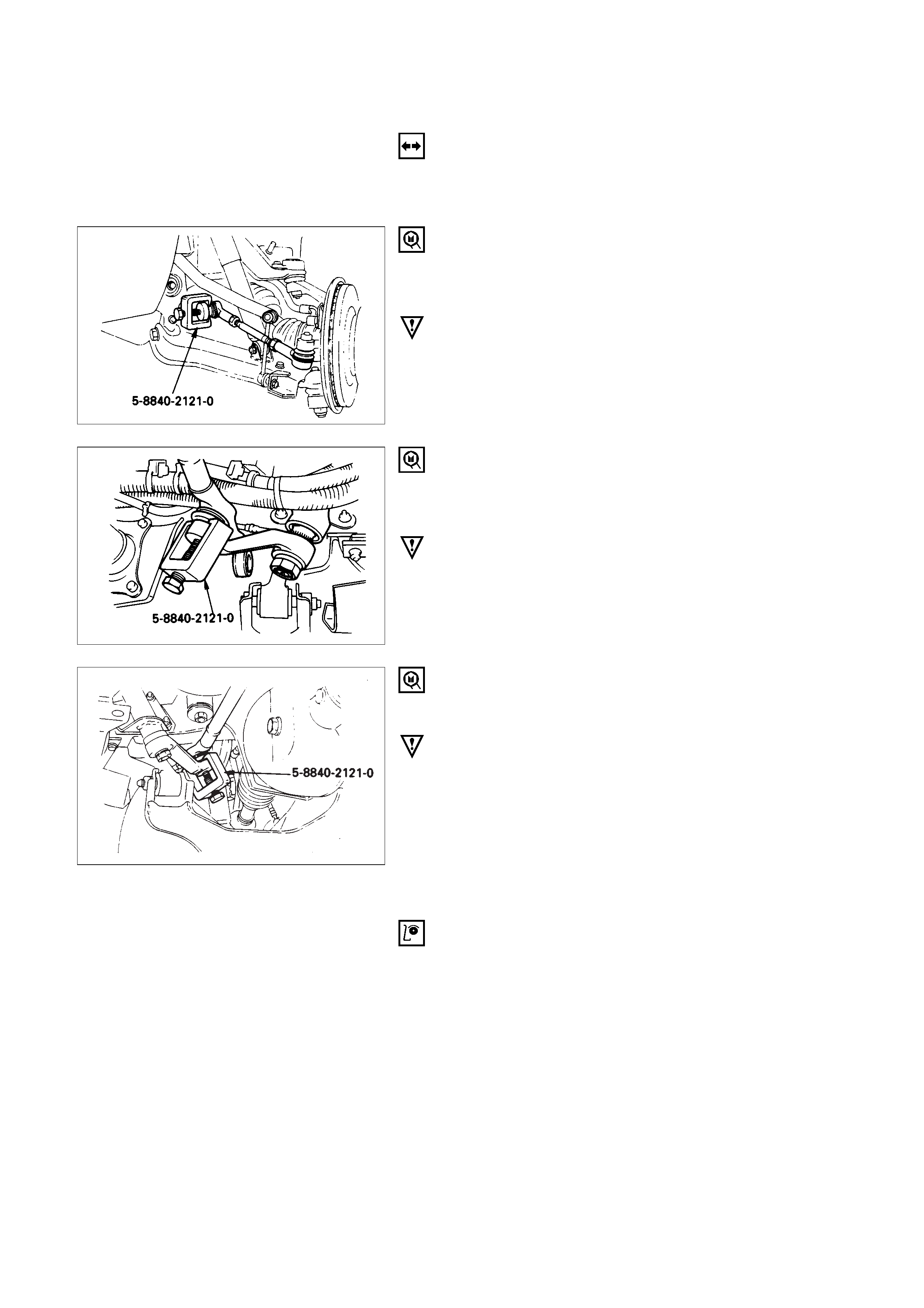
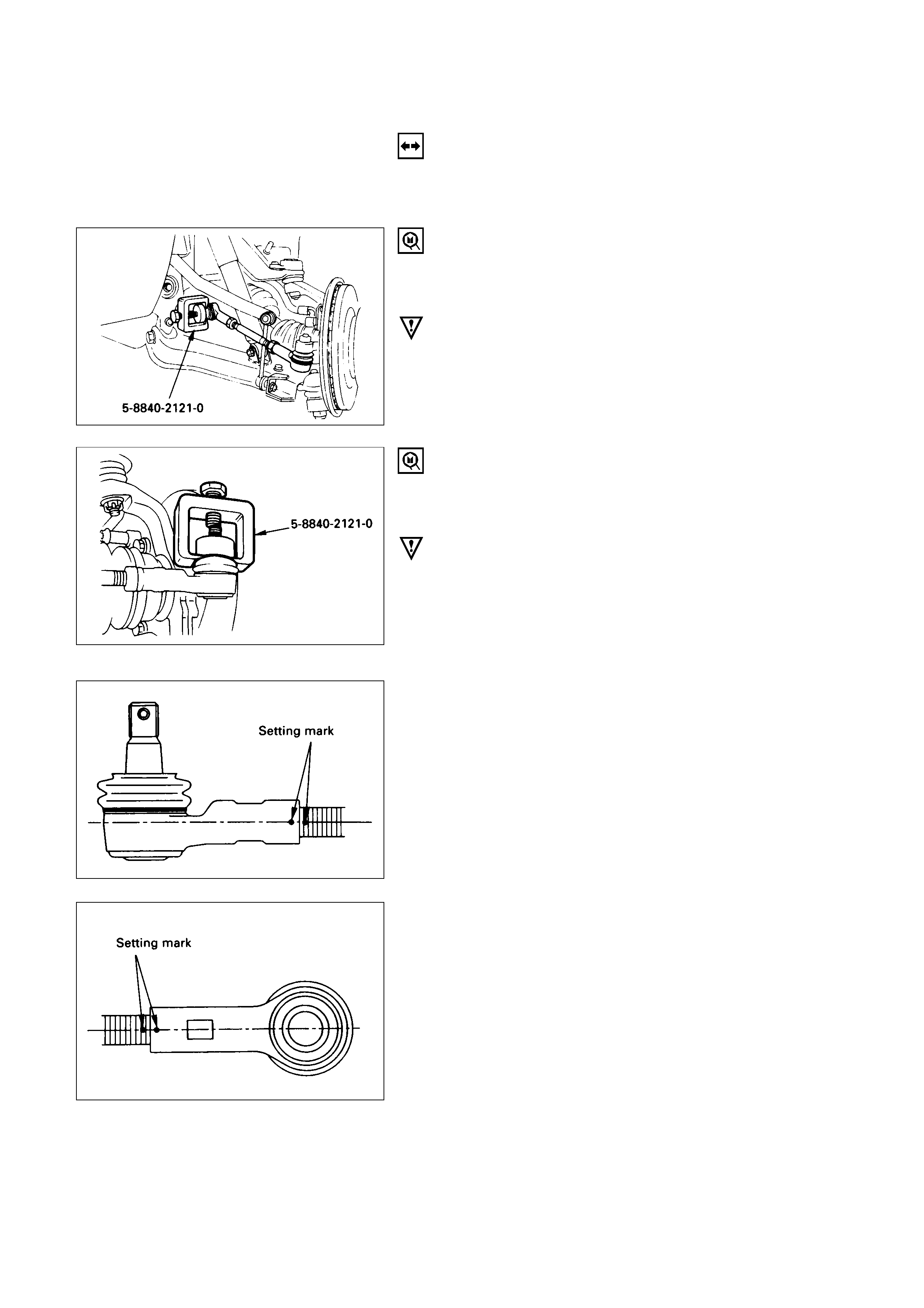
1.Nut and Cotter Pin
Disconnect outer track rod assembly from the center
track rod.
Remover: 5-8840-2121-0 (J-36831)
CAUTION:
Be careful not to break the ball joint boot.
2.Nut and Cotter Pin, Pitman Arm
Remove pitman arm from the center track rod (Fig.
3B3-4)
Remover: 5-8840-2121-0 (J-36831)
CAUTION:
Be careful not to break the ball joint boot.
3.Nut and Cotter Pin, Relay Lever
Remove relay lever from the center track rod.
Remover: 5-8840-2121-0 (J-36831)
CAUTION:
Be careful not to break the ball joint boot.
4. Center Track Rod Assembly
INSPECTION AND REPAIR
Make necessary correction or parts replacement if wear,
damage, corrosion, bending, deteriorations or any other
abnormal condition are found through inspection.
Check the following parts.
•Ball joint (Boot, screws and tapered surfaces)
INSTALLATION
4. Center Track Rod Assembly
3. Nut and Cotter Pin, Relay Lever
Tighten the nut to the specified torque, with just
enough additional torque to align cotter pin holes.
Install new cotter pin.
Relay Lever Nut Torque N·m (kg·m/lb·ft)
59 (6.0 / 43)
2. Nut and Cotter Pin, Pitman Arm
Tighten the nut to the specified torque, with just
enough additional torque to align cotter pin hole.
Install new cotter pin.
Pitman Arm Nut Torque N·m (kg·m/lb·ft)
98 (10.0 / 72)
1. Nut and Cotter Pins
Tighten the nut to the specified torque, with just
enough additional torque to align cotter pin holes.
Install new cotter pin.
Center Track Rod Nut Torque N·m (kg·m/lb·ft)
98 (10.0 / 72)
OUTER TRACK ROD ASSEMBLY
Removal Steps
1. Nut and cotter pin, center track rod
2. Nut and cotter pin, knuckle arm
3. Lock nut, outer
4. Rod end assembly outer
5. Lock nut, inner
6. Rod end assembly, inner
★The screw is threaded
counterclockwise.
Installation Steps
6. Rod end assembly, inner
5. Lock nut, inner
4. Rod end assembly outer
3. Lock nut, outer
2. Nut and cotter pin, knuckle arm
1. Nut and cotter pin, center track
rod
These steps are based on the LHD model.
REMOVAL
Preparation:
Remove wheel and tyre assembly.
Refer to “Wheels and Tyres” in section 10.
1.Nut and Cotter Pin, Center Track Rod
Disconnect outer track rod assembly at the center
track rod.
Remover: 5-8840-2121-0 (J-36831)
CAUTION:
Be careful not to break the ball joint boot.
2. Nut and Cotter Pin, Knuckle Arm
Remove outer track rod assembly from the knuckle
arm.
Remover: 5-8840-2121-0 (J-36831)
CAUTION:
Be careful not to break the ball joint boot.
3. Lock Nut, Outer
NOTE:
In either outer rod, the screw on the right side of the
vehicle is threaded counterclockwise.
6. Rod End, Inner
Apply setting marks to ensure reassembly of the
parts in their original position.
4. Rod End Assembly, Outer
Apply setting marks to ensure reassembly of the
parts in their original position.
5. Lock Nut, Inner
NOTE:
In either outer rod, the screw on the right side of the
vehicle is threaded counterclockwise.
INSPECTIONANDREPAIR
Make necessary correction or parts replacement if wear,
damage, corrosion, bending, deteriorations or any other
abnormal condition are found through inspection.
Check the following parts.
•Rod end assembly
•Ball joint (Boot, screws and tapered surfaces)
INSTALLATION
6.Rod End, Inner
Align the setting marks applied during desassembly.
5.Lock Nut, Inner
Lock Nut Torque N·m (kg·m/lb·ft)
118 (12.0 / 87)
NOTE:
In either outer rod, the screw on the right side of the
vehicle is threaded counterclockwise.
4.Rod End Assembly, Outer
Align the setting marks applied during disassembly.
3Lock Nut, Outer
Lock Nut TorqueN·m (kg·m/lb·ft)
118 (12.0 / 87)
2.Nut and Cotter pin, Knuckle Arm
Tighten the nut to the specified torque, with just
enough additional torque to align cotter pin holes.
Install new cotter pin.
Knuckle Arm Nut TorqueN·m (kg·m/lb·ft)
98 (10.0 / 72)
1.Nut and Cotter Pin, Center Track Rod
Tighten the nut to the specified torque, with just
enough additional torque to align cotter pin holes.
Install new cotter pin.
Track Rod Nut TorqueN·m (kg·m/lb·ft)
98 (10.0 / 72)
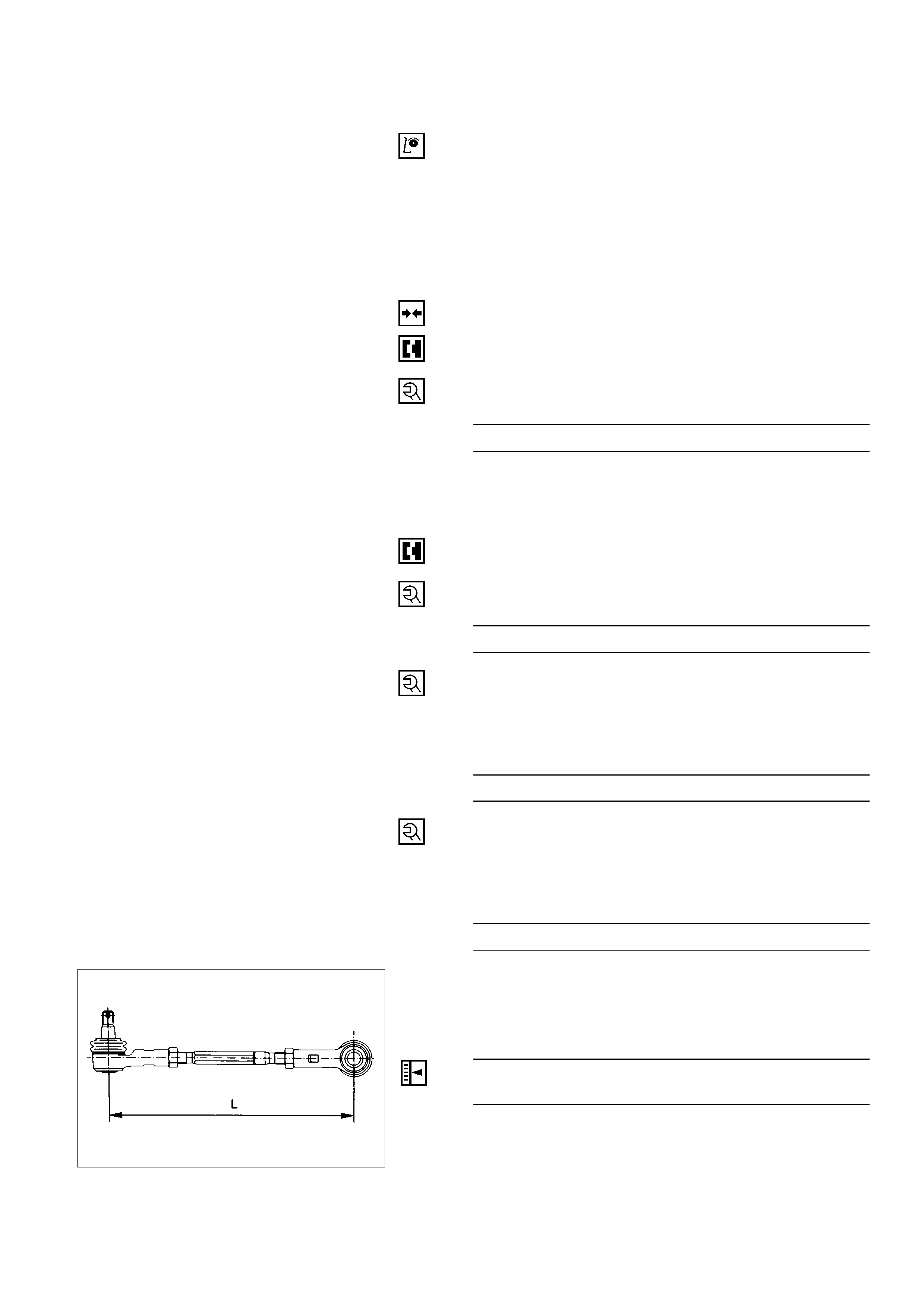
NOTE:
If replacing the track rod, adjust the new track rod
length.
Rod Length (L)mm (in)
328.3 (12.93) : Wide Tread
299 (11.77) : Narrow Tread
NOTE:
Adjust the toe-in. Refer to “Front End Alignment” in
section 3A.
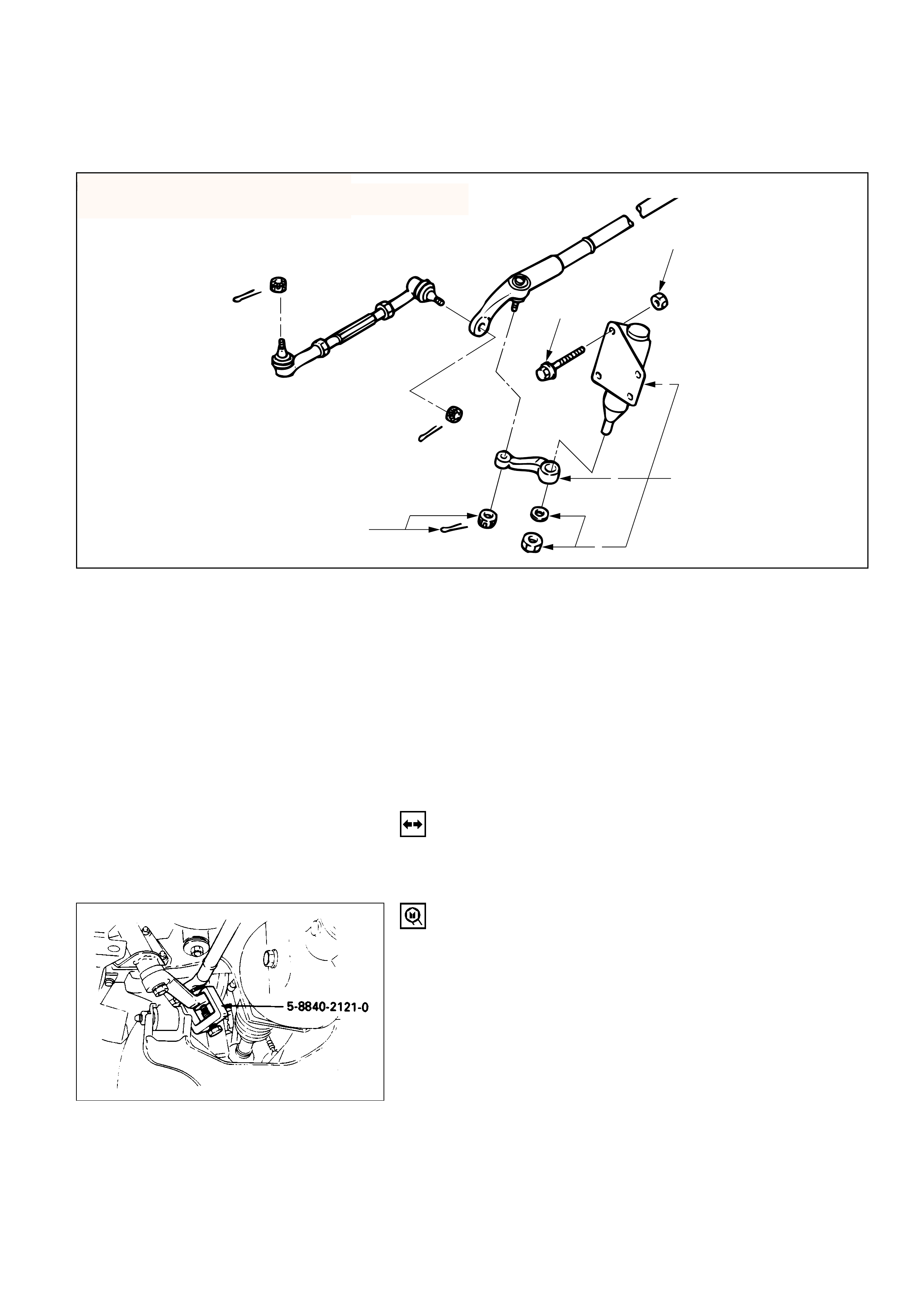
RELAY LEVER
2
2
3
6
5
4
1
hese steps are based on the LHD model.
Removal Steps
1. Nut and cotter pin
2. Bolt and nut
3. Relay lever and Bracket
4. Nut and washer
5. Relay lever
6. Bracket
Installation Steps
6. Bracket
5. Relay lever
4. Nut and washer
3. Relay lever and bracket
2. Bolt and nut
1. Nut and cotter pin
REMOVAL
Preparation:
Raise the vehicle and support the frame with suitable
safety stands.
1. Nut and Cotter pin
Disconnect relay lever at the center track rod.
Remover: 5-8840-2121-0 (J-36831)
433RW005
These steps are based on the LHD model.
2. Bolt and Nut
Remove stabiliser bar bolts and nuts and push the
stabilizer bar aside and remove the bolts and nuts.
3. Relay Lever and Bracket
4. Nut and Washer
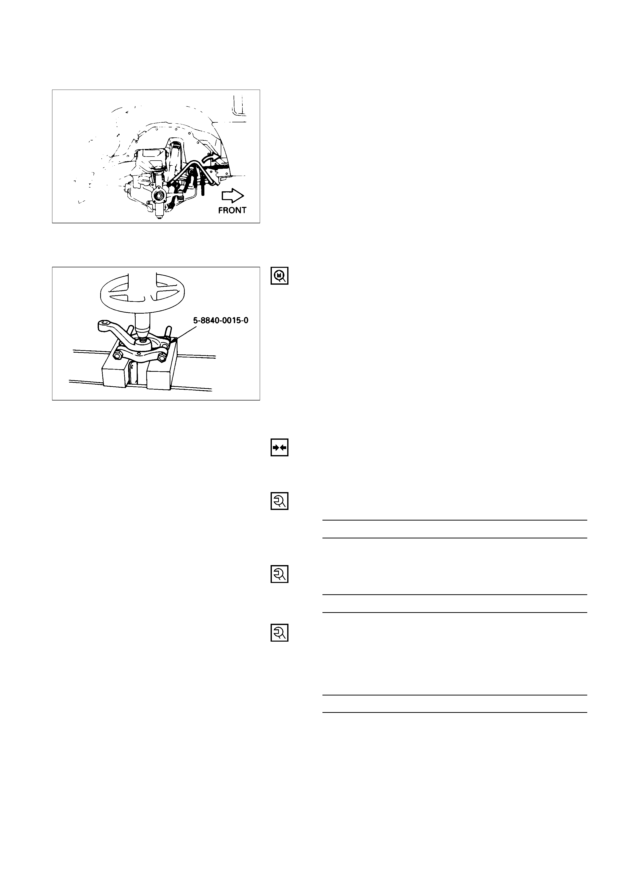
5. Relay Lever
Remove relay lever from the bracket.
Remover: 5-8840-0015-0 (J-22912-01)
6. Bracket
INSTALLATION
6. Bracket
5. Relay Lever
4. Nut and Washer
Relay Lever Nut Torque N·m (kg·m/lb·ft)
118 (12.0 / 87)
3. Relay Lever and Bracket
2. Bolt and Nut
Bracket Nut Torque N·m (kg·m/lb·ft)
44 (4.5 / 33)
1. Nut and Cotter Pin
Tighten the nut to the specified torque, with just
enough additional torque to align cotter pin holes.
Install new cotter pin.
Relay Lever Nut Torque N·m (kg·m/lb·ft)
59 (6.0 / 43)