
SECTION 9C - STEERING WHEEL & COLUMN
CAUTION:
When fasteners are removed, always reinstall them at the same location from which
they were removed. If a fastener needs to be replaced, use the correct part number
fastener for that application. If the correct part number fastener is not available, a
fastener of equal size and strength (or stronger) may be used. Fasteners that are not
reused, and those requiring thread locking compound, will be called out. The correct
torque value must be used when installing fasteners that require it. If the above
conditions are not followed, parts or system damage could result.
General Description
On-Vehicle Service
SRS Connectors
Inflator Module Replacement
Steering Wheel Replacement
Combination Switch Replacement
Lock Cylinder Replacement
Steering Column Replacement

This steering wheel and column repair section
covers the Supplemental Restraint System (SRS)
steering column. The following repair procedures
are specific to SRS Components. When servicing a
vehicle equipped with Supplemental Restraint
System, pay close attention to all WARNINGS and
CAUTIONS.
For detailed explanation about SRS, refer to Section
12M "SUPPLEMENTAL RESTRAINT SYSTEM (SRS)"
of manual.
The steering column has three important features in
addition to the steering function:
1. The column is energy absorbing, designed to
compress in a front-end collision to minimize
the possibility of injury to the driver of the
vehicle.
2. The ignition switch and lock are mounted
conveniently on the column.
3. With the column mounted lock, the ignition
and steering operation can be locked to
prevent theft of the vehicle.
The column may be disassembled and
reassembled. To insure the energy absorbing
action, it is important that the specified screws,
bolts and nuts be used only as designated and that
they are tightened to the specified torque.
When the column is removed from the vehicle, a
sharp blow on the end of steering shaft or shift
lever, leaning on the column assembly, or dropping
the assembly could shear or loosen the fasteners
that maintain column rigidity.
WARNING
THIS VEHICLE HAS A SUPPLEMENTAL RE-
STRAINT SYSTEM (SRS). REFER TO THE SRS
COMPONENT AND WIRING LOCATION VIEW
IN ORDER TO DETERMINE WHETHER YOU ARE
PERFORMING SERVICE ON OR NEAR THE SRS
COMPONENTS OR THE SRS WIRING. WHEN
YOU ARE PERFORMING SERVICE ON OR NEAR
THE SRS COMPONENTS OR THE SRS WIRING,
REFER TO THE SRS SERVICE INFORMATION.
FAILURE TO FOLLOW WARNINGS COULD RE-
SULT IN POSSIBLE AIR BAG DEPLOYMENT,
PERSONAL INJURY, OR OTHERWISE UN-
NEEDED SRS SYSTEM REPAIRS.
SAFE HANDLING OF INFLATOR MODULES
REQUIRES FOLLOWING THE PROCEDURES
DESCRIBED BELOW FOR BOTH LIVE AND
DEPLOYED MODULES.
SAFETY PRECAUTIONS MUST BE FOLLOWED
WHEN HANDLING A DEPLOYED AIR BAG AS-
SEMBLY (AIR BAG). AFTER DEPLOYMENT,
THE AIR BAG ASSEMBLY (AIR BAG) SURFACE
MAY CONTAIN A SMALL AMOUNT OF SODIUM
HYDROXIDE, A BY-PRODUCT OF THE DEPLOY-
MENT REACTION, THAT IS IRRITATING TO THE
SKIN AND EYES. MOST OF THE POWDER ON
THE AIR BAG ASSEMBLY (AIR BAG) IS HARM-
LESS. AS A PRECAUTION, WEAR GLOVES
AND SAFETY GLASSES WHEN HANDLING A
DEPLOYED AIR BAG ASSEMBLY, AND WASH
YOUR HANDS WITH MILD SOAP AND WATER
AFTERWARDS.
WHEN CARRYING A LIVE AIR BAG ASSEMBLY,
MAKE SURE THE BAG AND TRIM COVER ARE
POINTED AWAY FROM YOU. NEVER CARRY
AN AIR BAG ASSEMBLY BY THE WIRES OR
CONNECTOR ON THE UNDERSIDE OF MODULE.
IN THE CASE OF AN ACCIDENTAL DEPLOY-
MENT, THE BAG WILL THEN DEPLOY WITH
MINIMAL CHANCE OF INJURY. WHEN PLACING
A LIVE AIR BAG ASSEMBLY ON A BENCH OR
OTHER SURFACE, ALWAYS FACE THE BAG AND
TRIM COVER UP, AWAY FROM THE SURFACE.
NEVER REST A STEERING COLUMN ASSEMBLY
ON THE STEERING WHEEL WITH THE AIR
BAG ASSEMBLY FACE DOWN AND COLUMN
VERTICAL. THIS IS NECESSARY SO THAT A
FREE SPACE IS PROVIDED TO ALLOW THE AIR
BAG ASSEMBLY TO EXPAND IN THE UNLIKELY
EVENT OF ACCIDENTAL DEPLOYMENT. OTHER-
WISE, PERSONAL INJURY COULD RESULT.
TO AVOID DEPLOYMENT WHEN TROUBLE
SHOOTING THE SRS SYSTEM, DO NOT USE
ELECTRICAL TEST EQUIPMENT, SUCH AS
BATTERY-POWERED OR A/C-POWERED VOLT-
METER, OHMMETER, ETC., OR ANY TYPE OF
ELECTRICAL EQUIPMENT OTHER THAN SPECI-
FIED IN THIS MANUAL. DO NOT USE A NON-
POWERED PROBE-TYPE TESTER.
INSTRUCTIONS IN THIS MANUAL MUST BE
FOLLOWED CAREFULLY, OTHERWISE PER-
SONAL INJURY MAY RESULT.
GENERAL DESCRIPTION
ON-VEHICLE SERVICE
21
827RW035
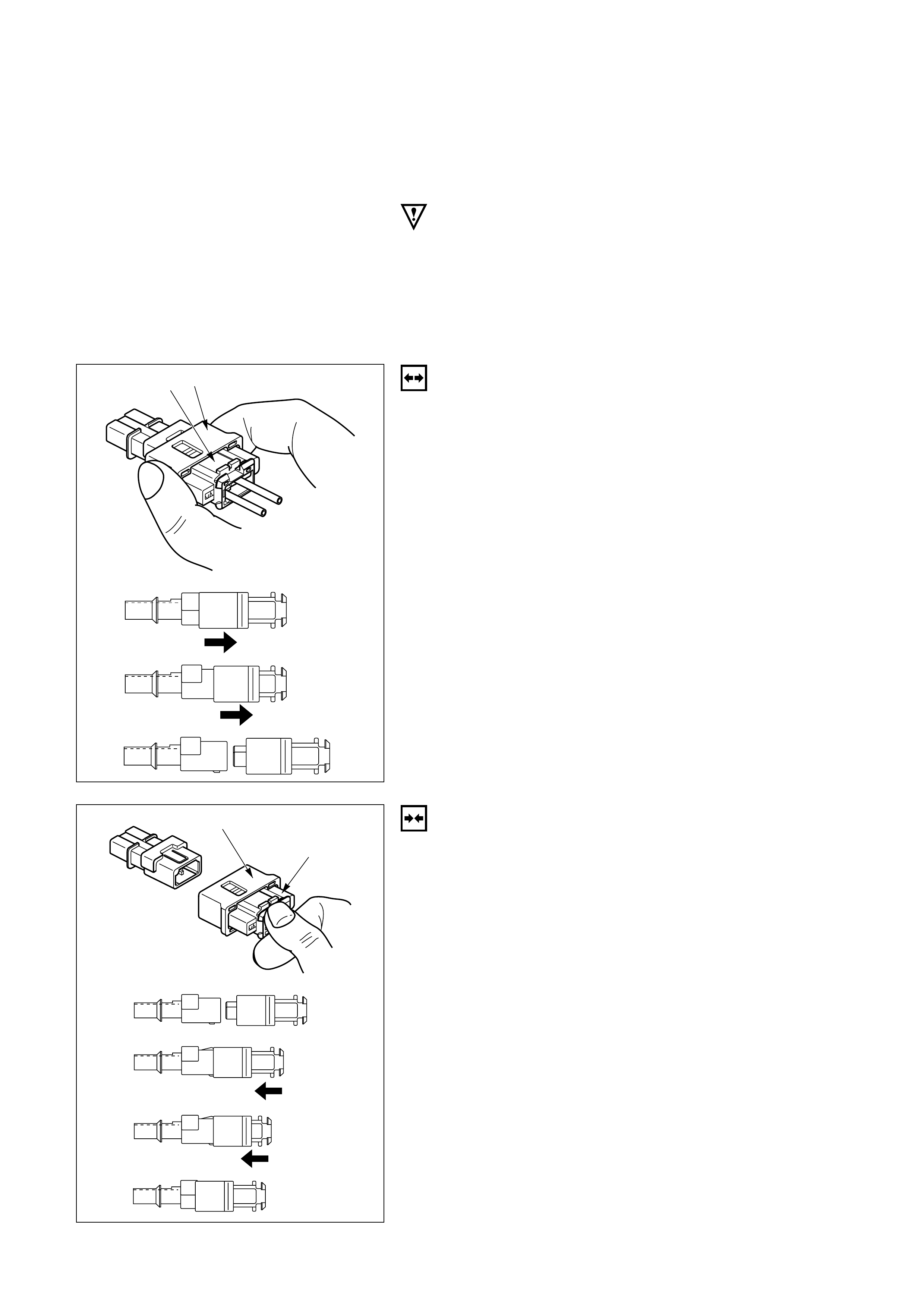
SRS CONNECTORS
CAUTION:
The special yellow color connectors are used for
supplemental restraint system-air bag circuit.
When removing the cable harness, do not pull the cables.
Otherwise, cable disconnection may occur.
When connect the SRS connector, insert the connector
completely. Imperfect locking may cause malfunction of
SRS circuit.
REMOVAL
To remove the connector, hold the cover insulator(1) and
pull it. The cover insulator slides and lock will be released.
Do not hold the socket insulator(2).
INSTALLATION
To install the connector, hold the socket insulator(1) and
insert it. The cover insulator slides and connector will be
locked.
Do not hold the cover insulator(2).
2
1
827RW034
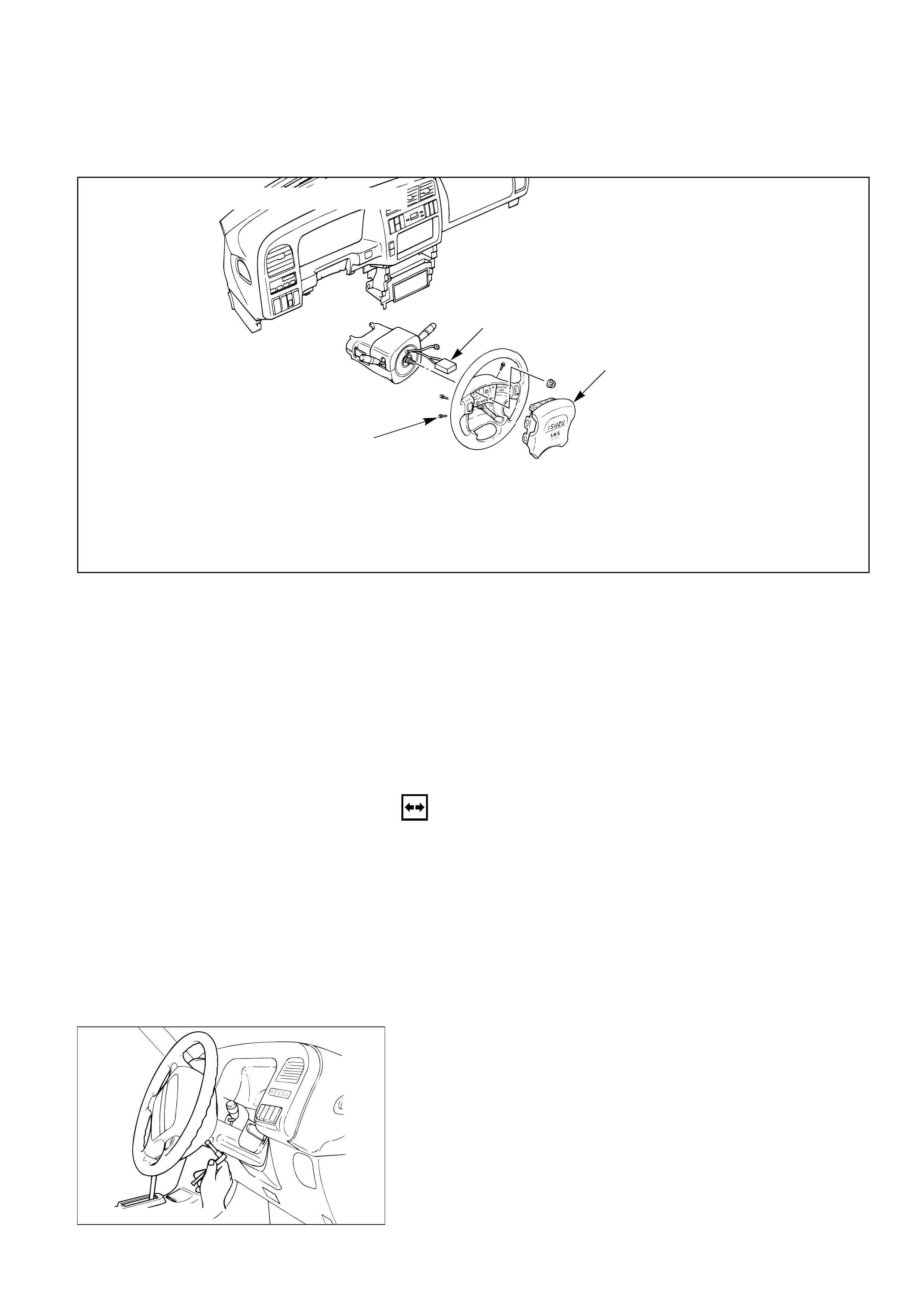
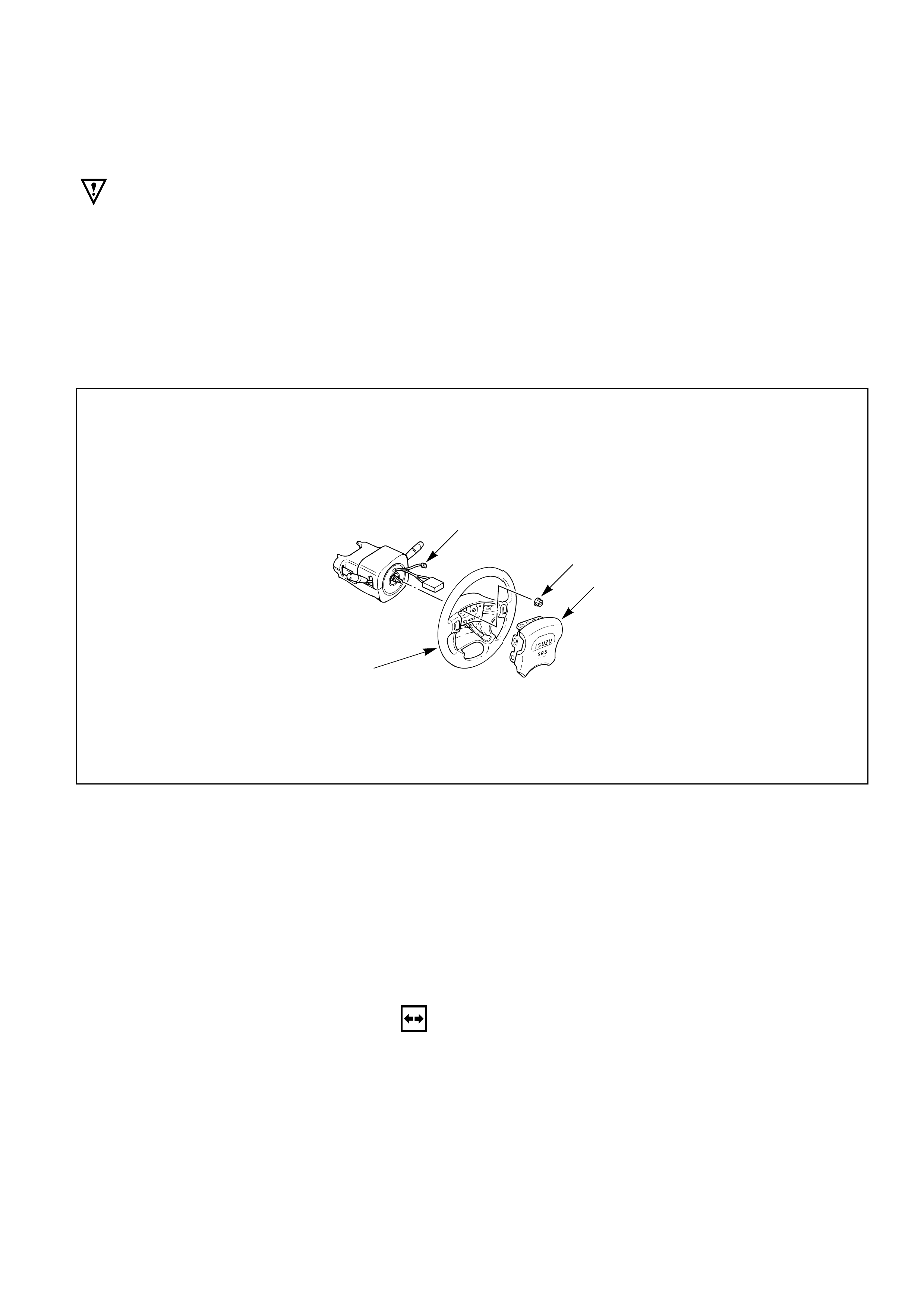
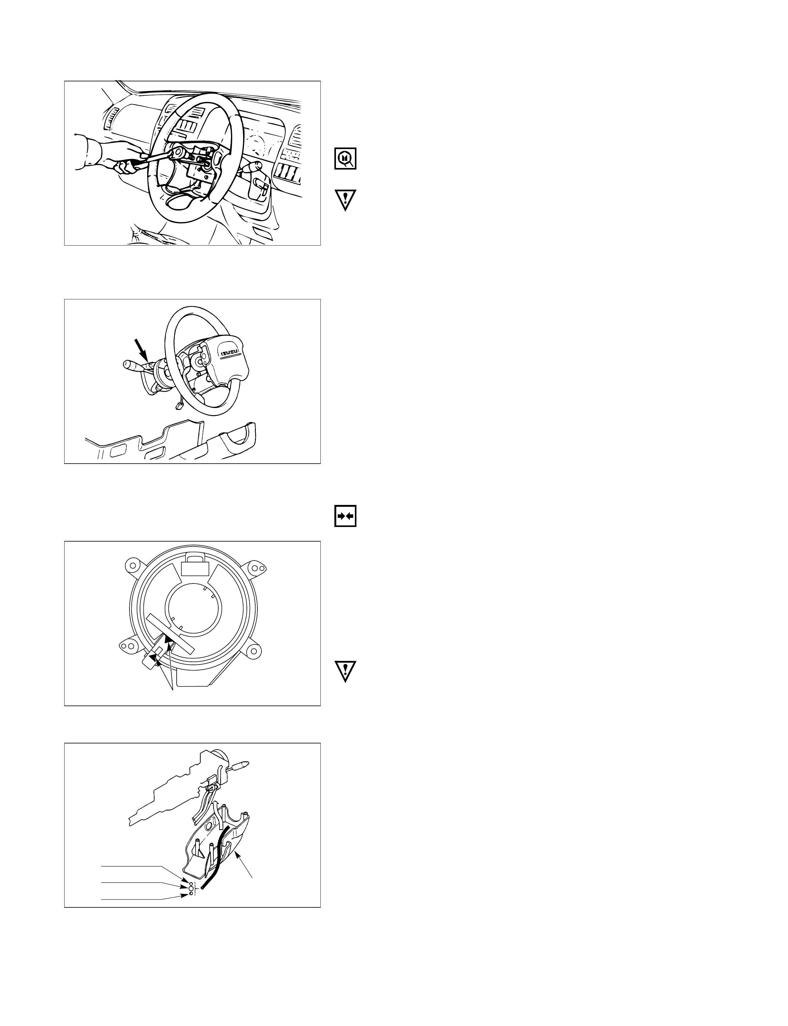
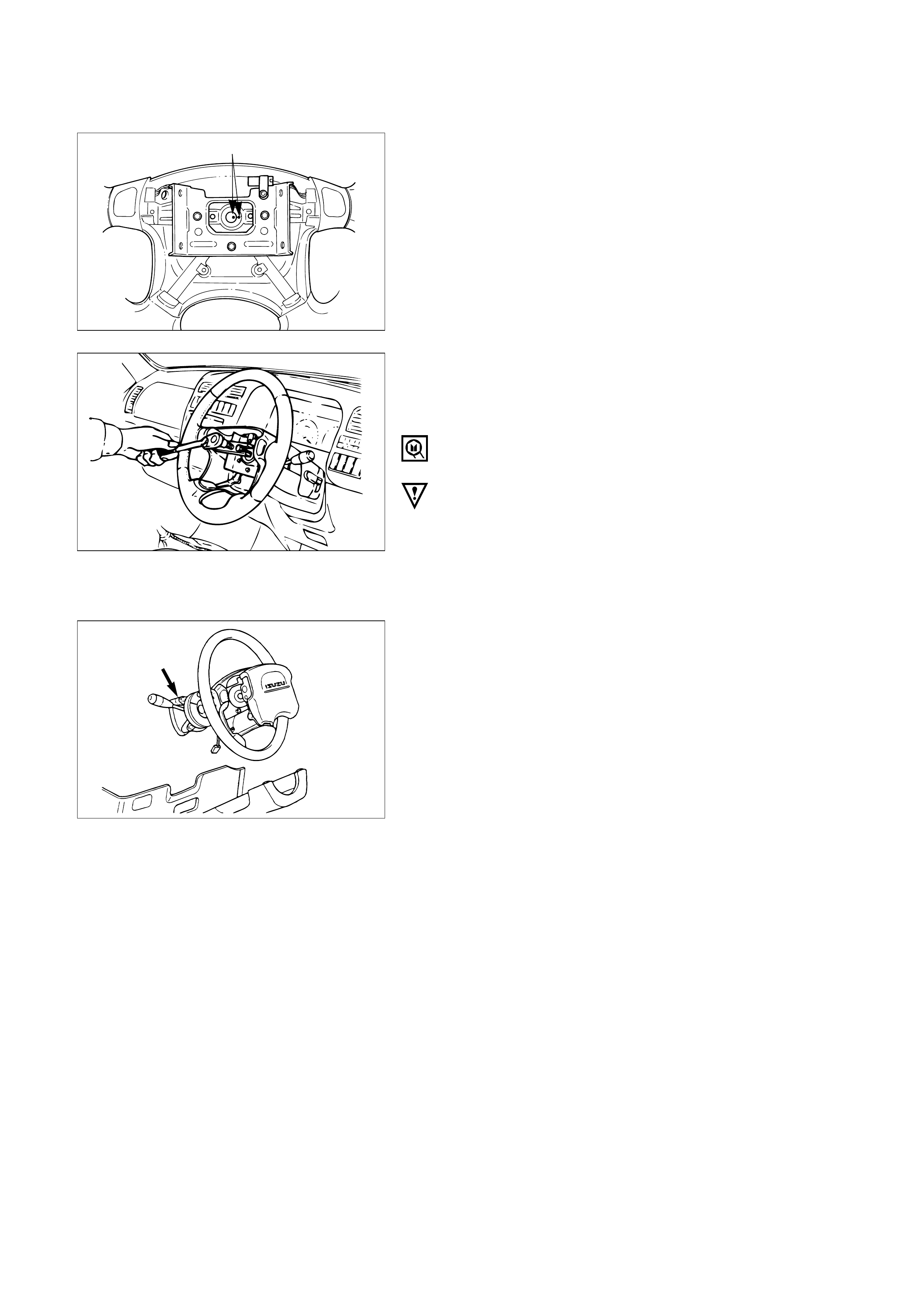
INFLATOR MODULE REPLACEMENT
1
3
2
Removal Steps
1. Fixing bolt
2. Module connector
3. Inflator module
Installation Steps
3. Inflator module
2. Module connector
1. Fixing bolt
REMOVAL
Preparation:
1) Turn the steering wheel so that the vehicle's wheels
are pointing straight ahead.
2) Turn the ignition switch to "LOCK".
3) Disconnect the battery ground cable, and wait at least
5 minutes.
4) Disconnect the yellow 2way SRS connector located
under the steering column.
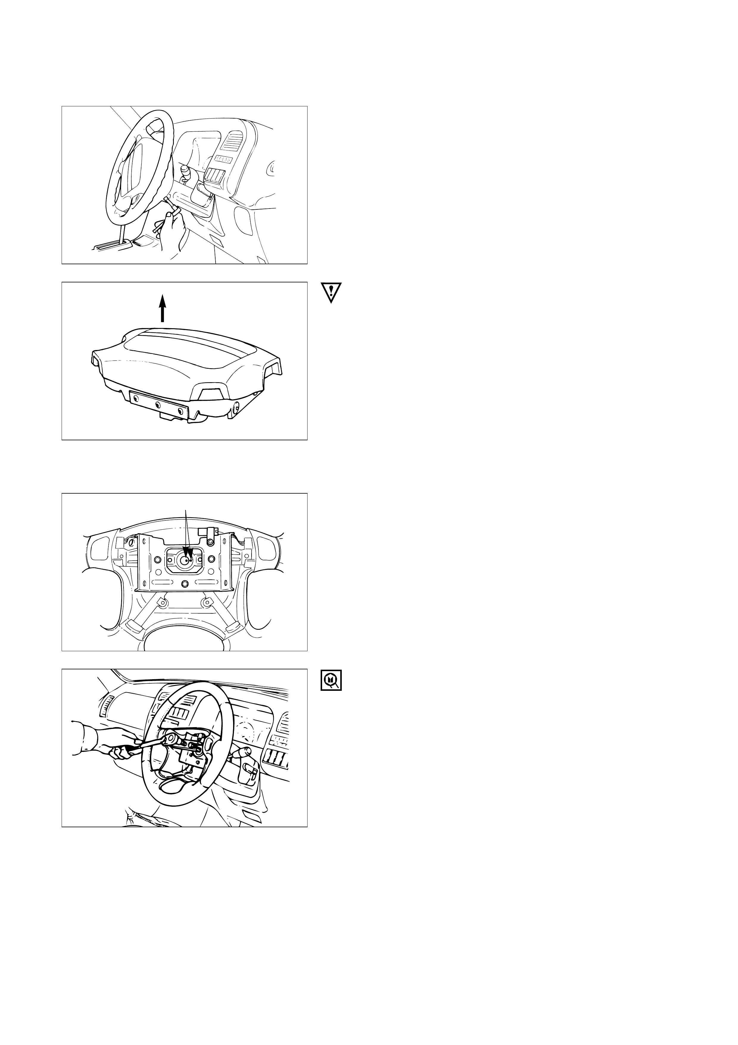
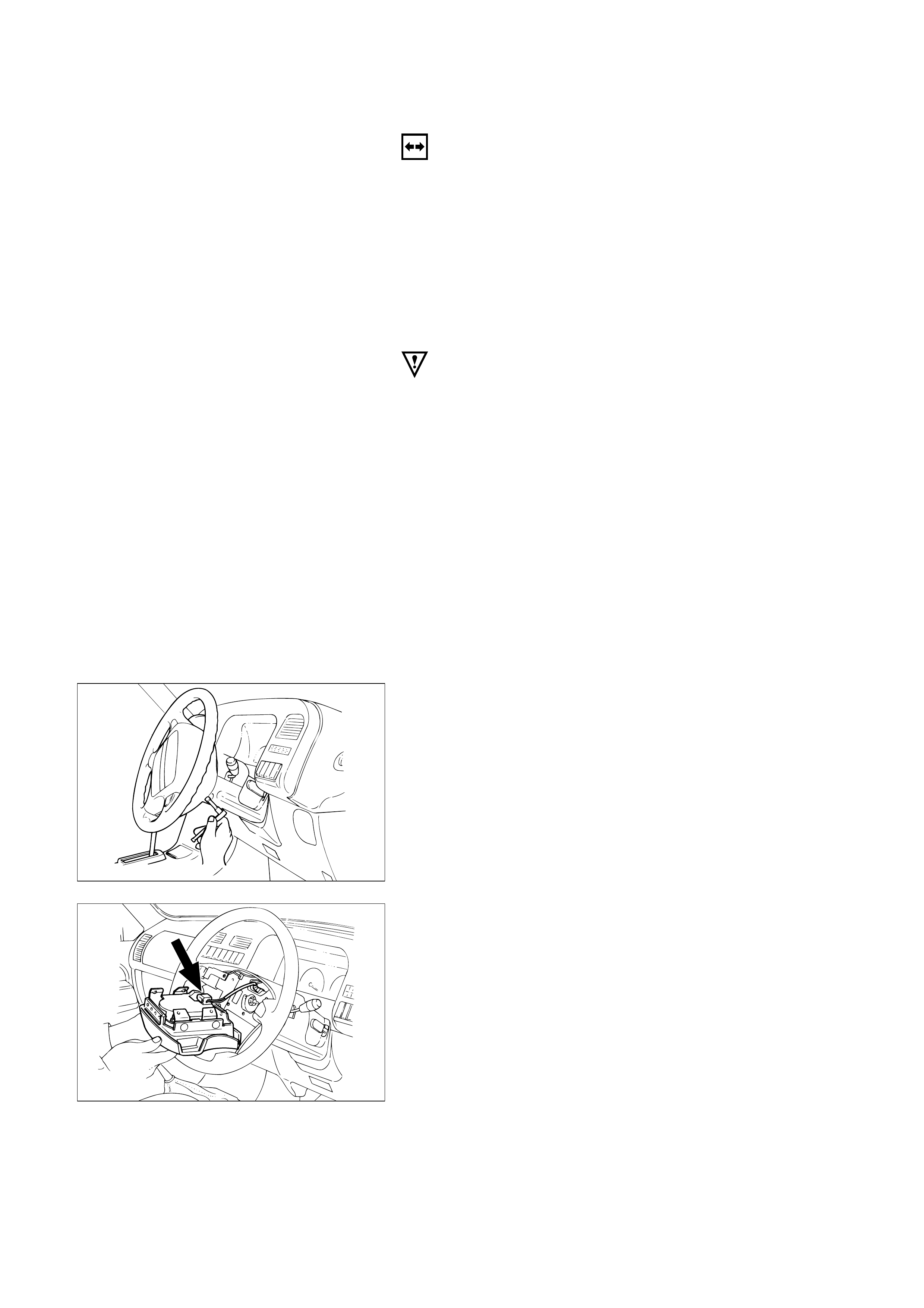
1. Fixing Bolt
Loosen the inflator module fixing bolt from behind
the steering wheel assembly using a TORX‚ driver or
equivalent until the inflator module can be released
from steering assembly.
827RT914
2. Module Connector
Disconnect the yellow 2way SRS connector located
behind the inflator module.
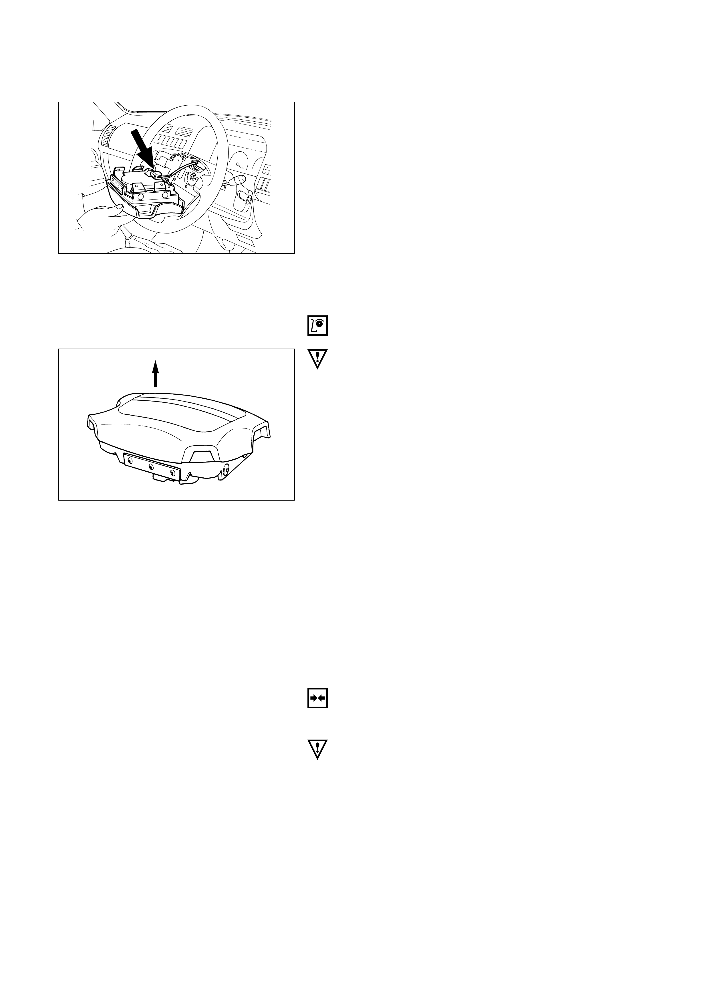
3. Inflator Module
827RW037
827RS016
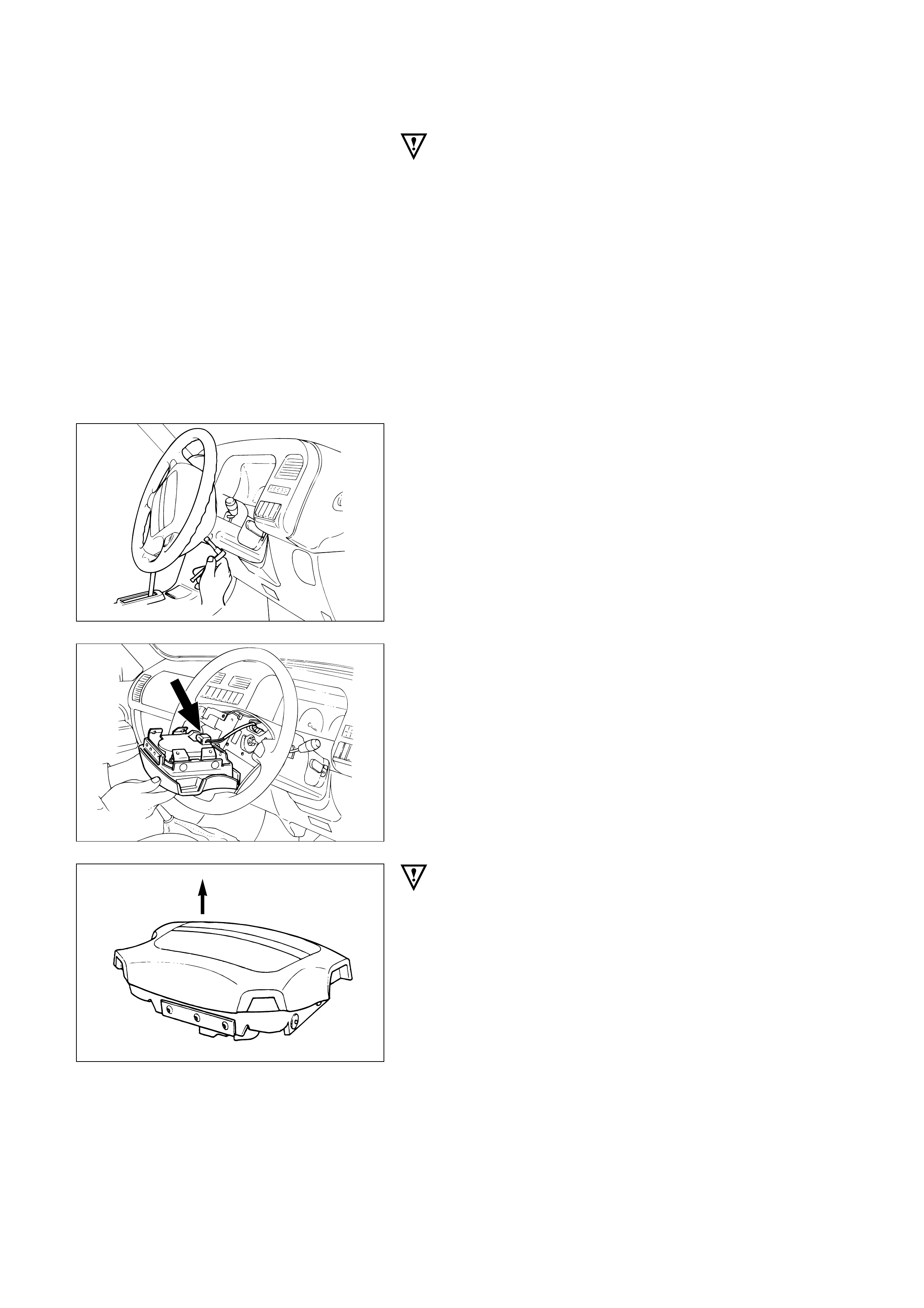
INSPECTION AND REPAIR
WARNING
THE INFLATOR MODULE SHOULD ALWAYS BE CARRIED
WITH THE URETHANE COVER AWAY FROM YOUR BODY
AND SHOULD ALWAYS BE LAID ON A FLAT SURFACE
WITH THE URETHANE SIDE UP. THIS IS NECESSARY
BECAUSE A FREE SPACE IS PROVIDED TO ALLOW THE
AIR CUSHION TO EXPAND IN THE UNLIKELY EVENT OF
ACCIDENTAL DEPLOYMENT. OTHERWISE, PERSONAL
INJURY MAY BE RESULT.
The Inflator module consists of a cover, air bag,
inflator, and retainer. Inspect the Inflator module
mainly for the following:
1) Check for holes, cracks, severe blemishes and
deformation on the cover.
2) Check that the retainer is not deformed.
3) Check for defects such as damage and breakage
in the lead wire of the squib.
If an abnormality is found as the result of the
inspection, replace the Inflator module with a new
one.
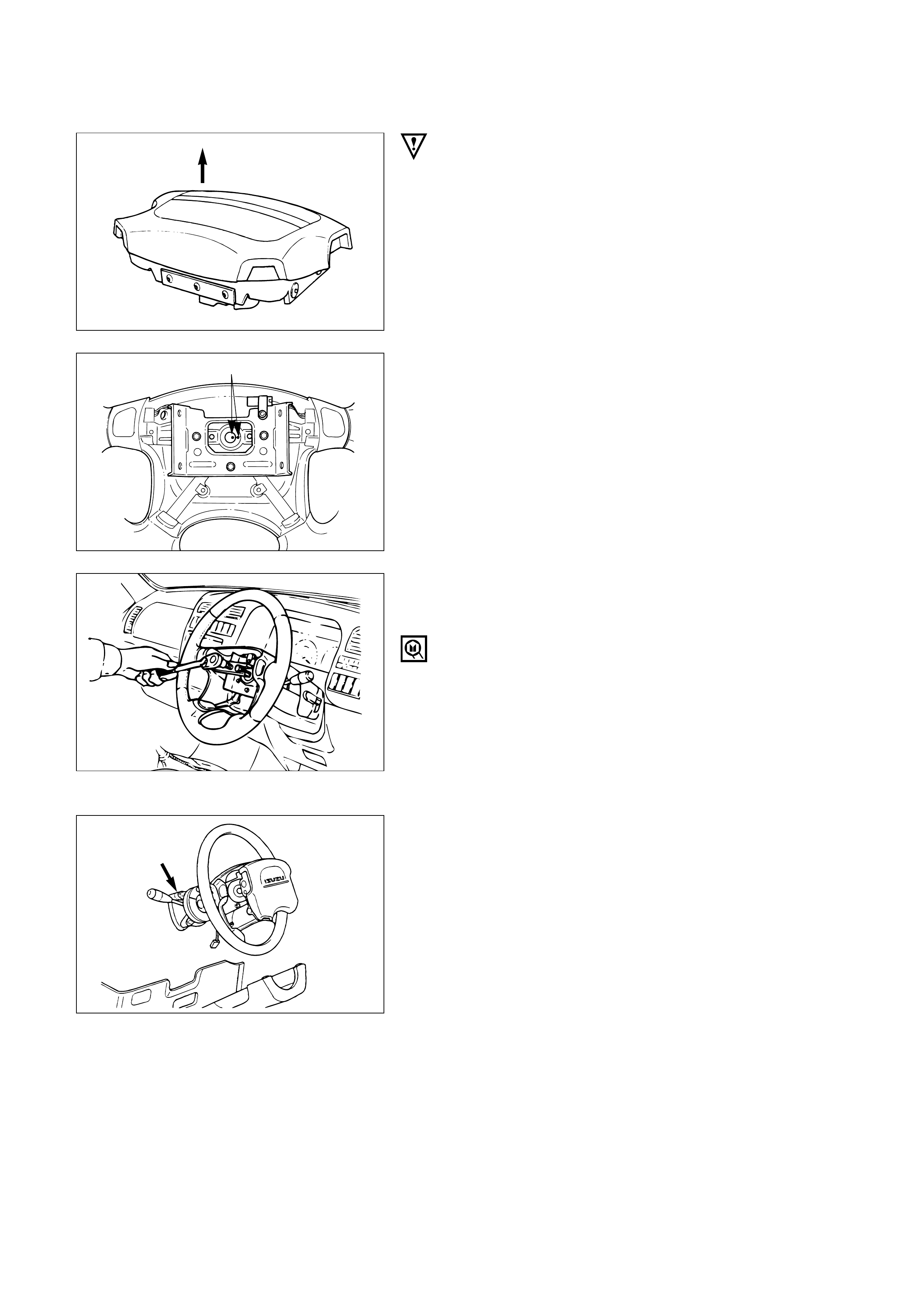
Up
INSTALLATION
3.Inflator Module
CAUTION:
•Never use the air bag assembly from another vehicle.
Use only the air bag assembly for "UBS".
•When replace the inflator module, use only same parts
number assembly. If different parts number assembly is
installed, the air bag system can not function correctly
because it has different characteristic.
2. Module Connector
Support the module and carefully connect the
module connector.
NOTE:
Pass the lead wire through the tabs on the plastic
cover (wire protector) of inflator to prevent lead wire
from being pinched.
3
4
1
2
1. Fixing Bolt
1) Secure the module with one bolt to relieve
weight on the connector wire.
2) Tighten bolts to specified sequence as figure.
N·m (kg·m/lb·in)
8 (0.8 / 69)
3) Connect the yellow 2way SRS connector located
under the steering column.
4) Connect the battery ground cable.
5) Set ignition to "ON" while watching warning
light. Light should flash 7 times and then go off.
If lamp does not operate correctly, refer to
Section 12M.
827RS017
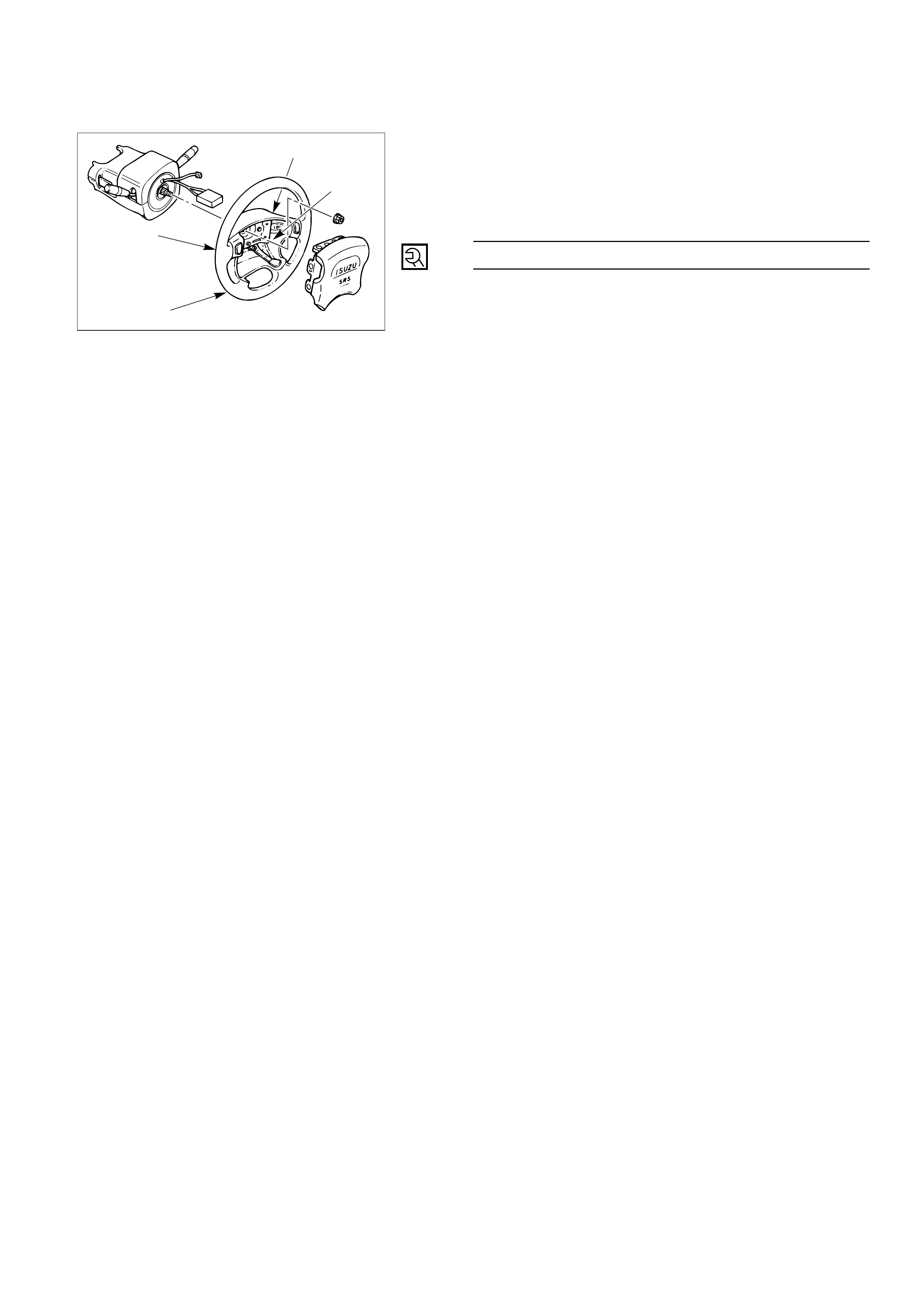
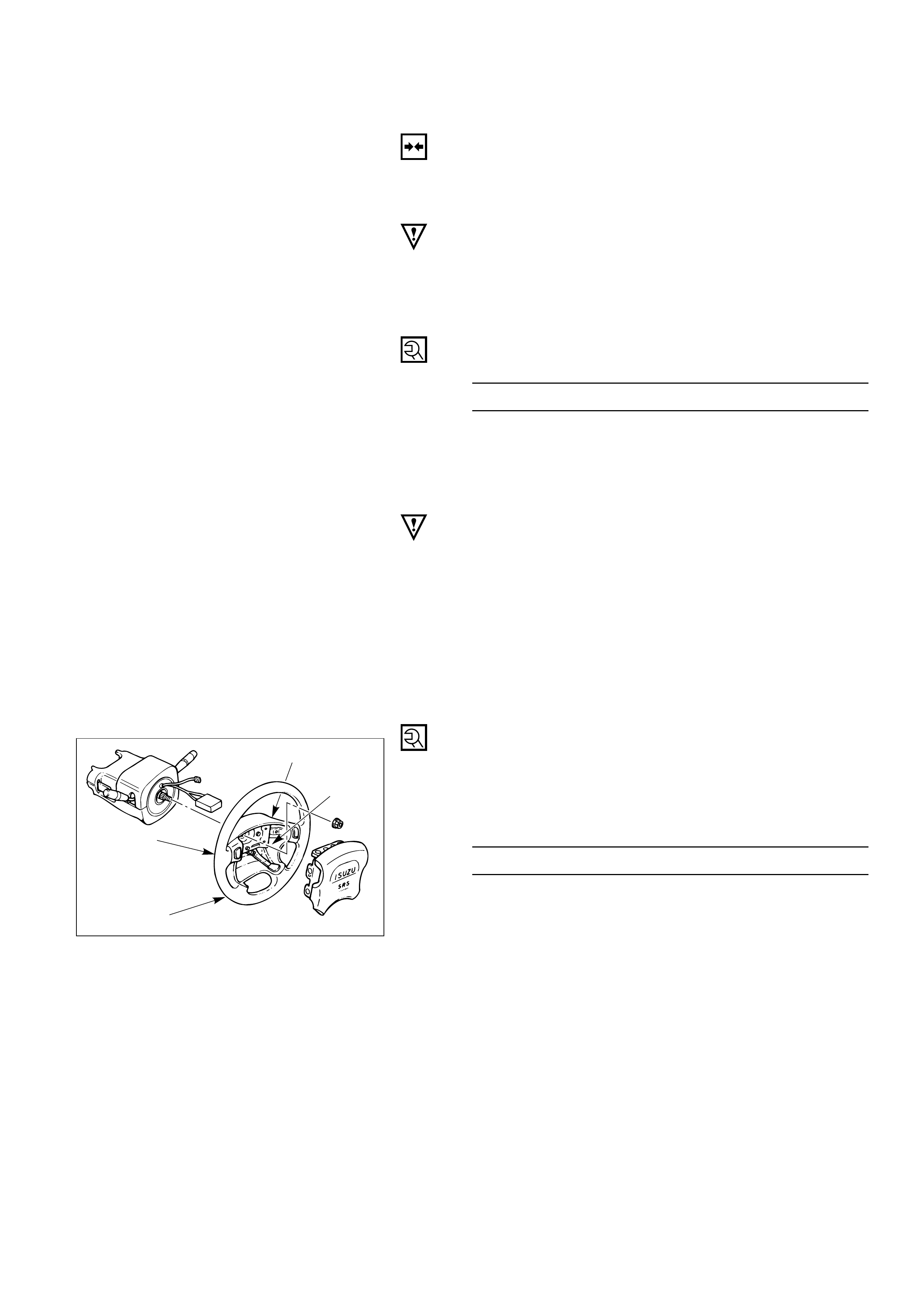
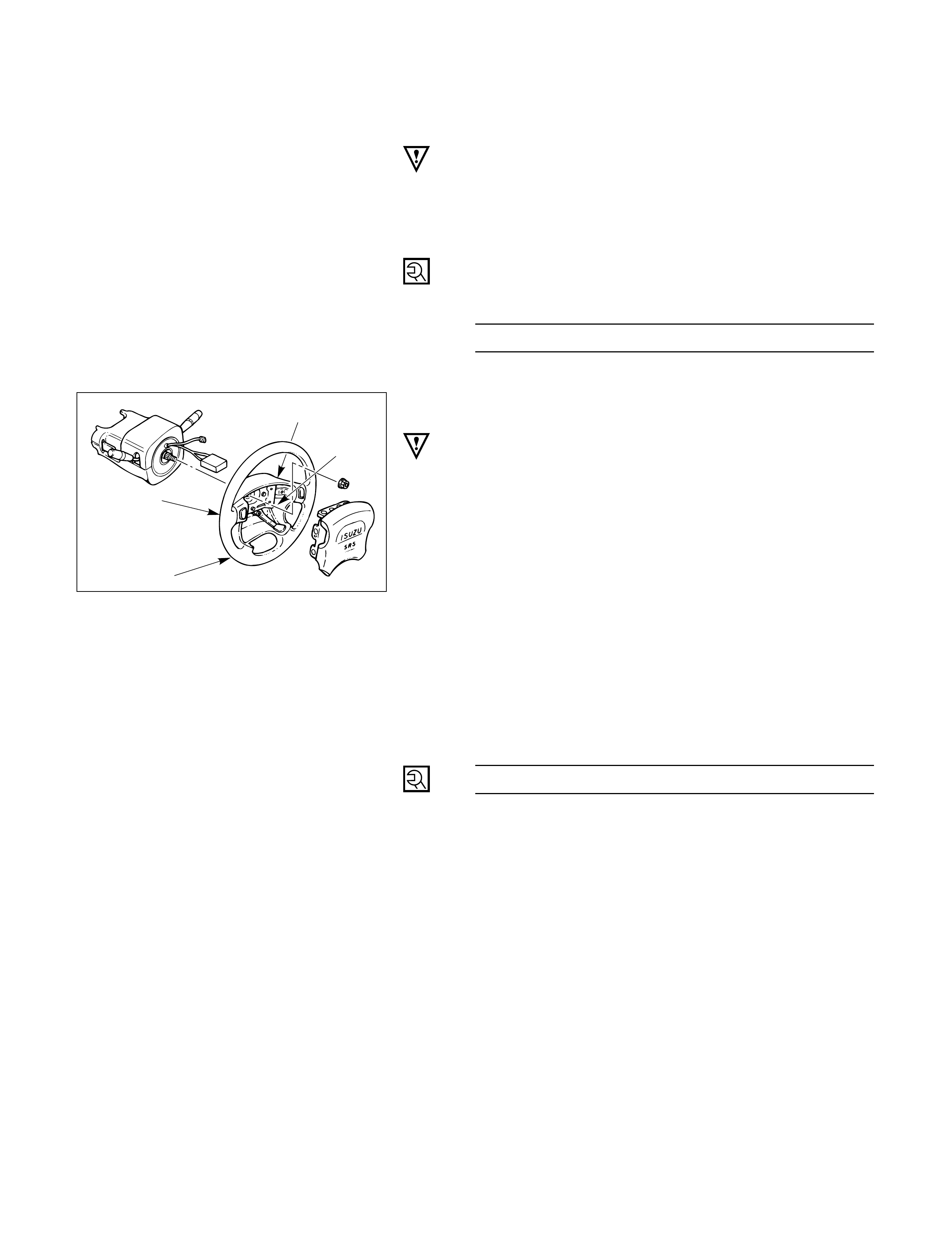
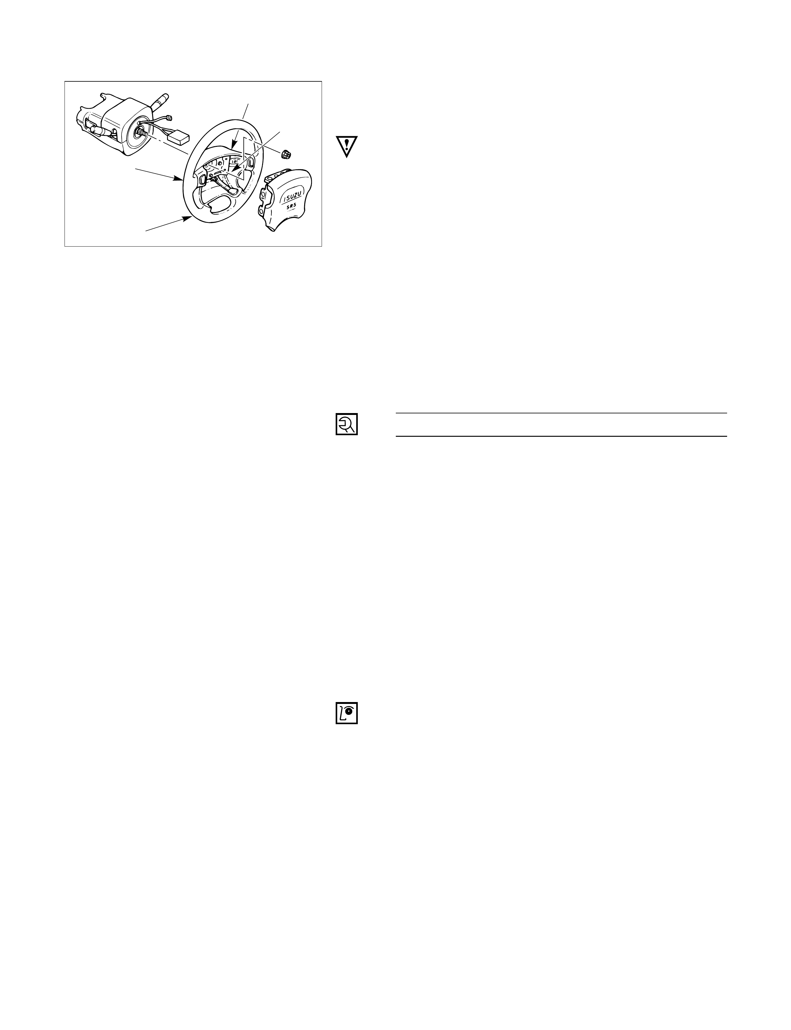
STEERING WHEEL REPLACEMENT
1
3
2
4
Removal Steps
1. Inflator module
2. Horn lead
3. Steering wheel fixing nut
4. Steering wheel
Installation Steps
4. Steering wheel
3. Steering wheel fixing nut
2. Horn lead
1. Inflator module
REMOVAL
Preparation:
1) Turn the steering wheel so that the vehicle's wheels
are pointing straight ahead.
2) Turn the ignition switch to "LOCK".
3) Disconnect the battery ground cable, and wait at least
5 minutes.
4) Disconnect the yellow 2way SRS connector located
under the steering column.
CAUTION:
Once the steering column is removed from the vehicle, the column is extremely suspectible to
damage. Dropping the column assembly on its end could collapse the steering shaft or loosen the
slide block which maintains column rigidity. Leaning on the column assembly could cause the jacket
to bend or deform. Any of the above damage could impair the column's collapsible design. If it is
necessary to remove the steering wheel, use only the specified steering wheel puller. Under no
conditions should the end of the shaft be hammered upon, as hammering could loosen slide block
which maintains column rigidity.
1. Inflator Module
1) Loosen the inflator module fixing bolt from
behind the steering wheel assembly using a
TORXdriver or equivalent until the inflator
module can be released from steering assembly.
2) Disconnect the yellow 2way SRS connector
located behind the inflator module.
WARNING
THE INFLATOR MODULE SHOULD ALWAYS BE CARRIED
WITH THE URETHANE COVER AWAY FROM YOUR BODY
AND SHOULD ALWAYS BE LAID ON A FLAT SURFACE
WITH THE URETHANE SIDE UP. THIS IS NECESSARY
BECAUSE A FREE SPACE IS PROVIDED TO ALLOW THE
AIR CUSHION TO EXPAND IN THE UNLIKELY EVENT OF
ACCIDENTAL DEPLOYMENT. OTHERWISE, PERSONAL
INJURY MAY RESULT.
2. Horn Lead
3. Steering Wheel Fixing Nut
4. Steering Wheel
1) Apply a setting mark across the steering wheel
and shaft so parts can be reassembled in their
original position.
2) Move the front wheels to the straight ahead
position and use special tool.
Steering wheel remover: 5-8840-0016-0 (J-29752)
NOTE:
Never apply force to the steering wheel in direction
of the shaft by using a hammer or other impact tools
in an attempt to remove the steering wheel. The
steering shaft is designed as an energy absorbing
unit.
827RT914
827RS016
430RS004
Up
Setting mark
430RW014
INSTALLATION
4. Steering Wheel
Align the setting marks made when removing.
CAUTION:
Never apply force to the setting wheel in direction of the
shaft by using a hammer or other impact tools in an
attempt to install the steering wheel. The setting shaft is
designed as an energy absorbing unit.
3. Steering Wheel Fixing Nut
Steering Wheel Nut Torque N·m (kg·m/lb·ft)
8 (0.8 / 69)
4) Connect the yellow 2way SRS connector located
under the steering column.
5) Connect the battery ground cable.
6) Set ignition to "ON" while watching warning
light. Light should flash 7 times and then go off.
If lamp does not operate correctly, refer to
Section 12M.
3
4
1
2
827RS017
34 (3.5 / 25)
2. Horn Lead
1. Inflator Module
1) Support the module and carefully connect the
module connector.
CAUTION:
•Never use the air bag assembly from another vehicle.
Use only the air bag assembly for "UBS".
•When replace the inflator module, use only same parts
number assembly. If different parts number assembly is
installed, the air bag system can not function correctly
because it has different characteristic.
NOTE:
Pass the lead wire through the tabs on the plastic
cover (wire protector) of inflator to prevent lead wire
from being pinches.
2) Secure the module with one bolt to relieve
weight on the connector wire.
3) Tighten bolts to specified sequence as figure.
Inflator module Bolt Torque N·m (kg·m/lb·in)
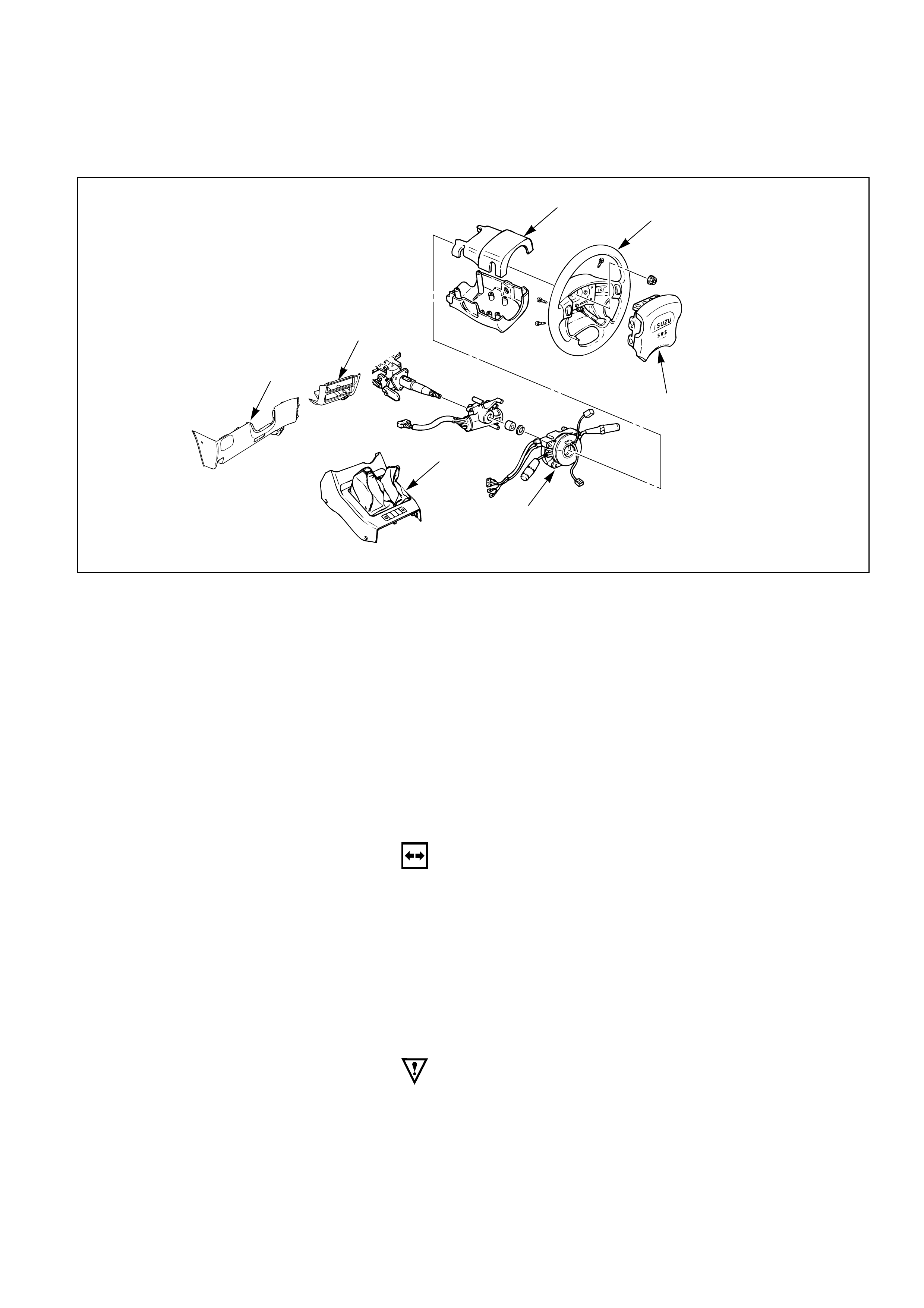
COMBINATION SWITCH REPLACEMENT
3
2
1
7
4
5
6
Removal Steps
1. Front console assembly
2. Lower cluster assembly
3. Steering lower cover
4. Inflator module
5. Steering wheel
6. Steering column cover
7. Combination switch and
SRS coil assembly
Installation Steps
7. Combination switch and
SRS coil assembly
6. Steering column cover
5. Steering wheel
4. Inflator module
3. Steering lower cover
2. Lower cluster assembly
1. Front console assembly
REMOVAL
Preparation:
1) Turn the steering wheel so that the vehicle's wheels
are pointing straight ahead.
2) Turn the ignition switch to "LOCK".
3) Disconnect the battery ground cable, and wait at least
5 minutes.
4) Disconnect the yellow 2way SRS connector located
under the steering column.
CAUTION:
The wheels of the vehicle must be straight ahead and the
steering column in the "LOCK" position before
disconnecting the steering wheel. Failure to do so will
cause the coil assembly to become uncentered which will
cause damage to the coil assembly.

1. Front Console Assembly
1) Remove the transmission (for M/T) and transfer
control lever knob.
2) Disconnect the wiring harness connectors.
2. Lower Cluster Assembly
3. Steering Lower Cover
Remove the engine hood opening lever.
4. Inflator Module
1) Loosen the inflator module fixing bolt from
behind the steering wheel assembly using a
TORXdriver or equivalent until the inflator
module can be released from steering assembly.
2) Disconnect the yellow 2way SRS connector
located behind the inflator module.
WARNING
THE INFLATOR MODULE SHOULD ALWAYS BE CARRIED
WITH THE URETHANE COVER AWAY FROM YOUR BODY
AND SHOULD ALWAYS BE LAID ON A FLAT SURFACE
WITH THE URETHANE SIDE UP. THIS IS NECESSARY
BECAUSE A FREE SPACE IS PROVIDED TO ALLOW THE
AIR CUSHION TO EXPAND IN THE UNLIKELY EVENT OF A
ACCIDENTAL DEPLOYMENT. OTHERWISE, PERSONAL
INJURY MAY RESULT.
5. Steering Wheel
Apply a setting mark across the steering wheel and
shaft so parts can be reassembled in their original
position.
827RT914
827RW037
827RS016
Up
430RS004
Setting mark
Use special tool. Remove the steering wheel.
Move the tires to the straight ahead position before
removing the steering wheel.
Steering wheel remover: 5-8840-0016-0 (J-29752)
CAUTION:
Never apply force to the steering wheel in direction of the
shaft by using a hammer or other impact tools in an
attempt to remove the steering wheel. The steering shaft
is designed as an energy absorbing unit.
6. Steering Column Cover
7. Combination Switch and SRS Coil Assembly
1) Disconnect the wiring harness connectors
located under the steering column.
2) Remove the combination switch assembly with
SRS coil.
NOTE:
The SRS coil is a part of the combination switch
assembly, which can not be replaced separately.
Therefore, be sure not to remove the SRS coil from
the combination switch assembly.
825RS046
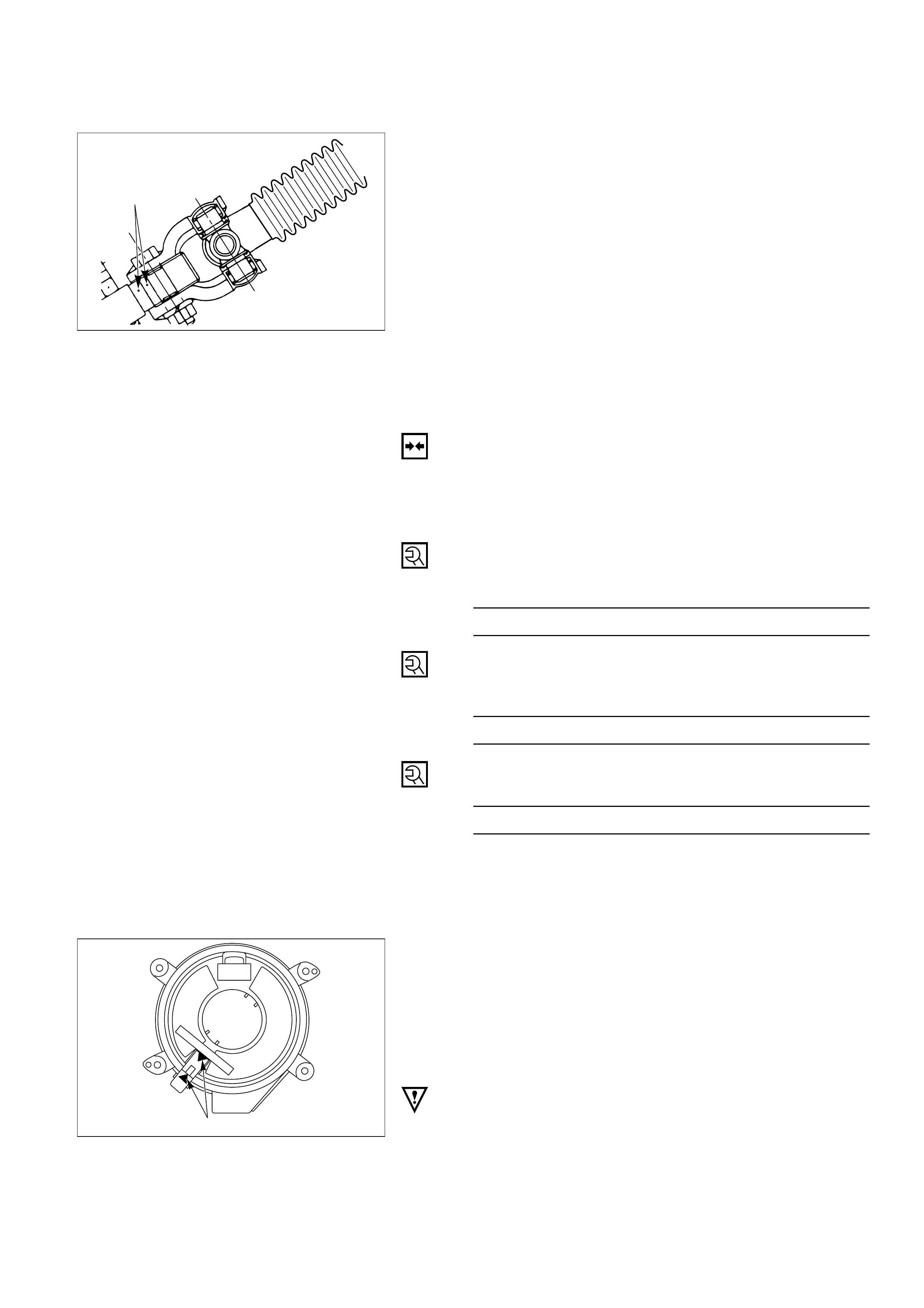
INSTALLATION
Alignment mark
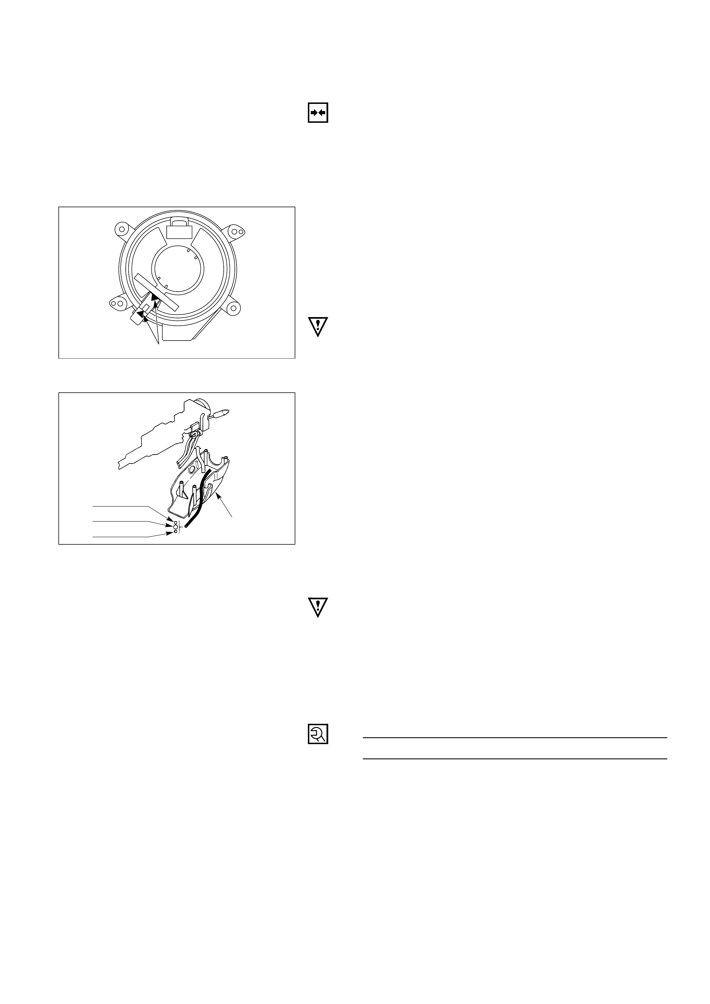
7. Combination Switch and SRS Coil Assembly
1) After installation of combination switch
assembly, connect the combination switch
wiring harness connector and the SRS 2way
connector located under the steering column.
2) Turn the SRS coil counterclockwise to full, return
about 3 turns and align the neutral mark.
CAUTION:
When turning the SRS coil counterclockwise to full, stop
turning if resistance is felt. Forced further turning may
damage to the cable in the SRS coil.
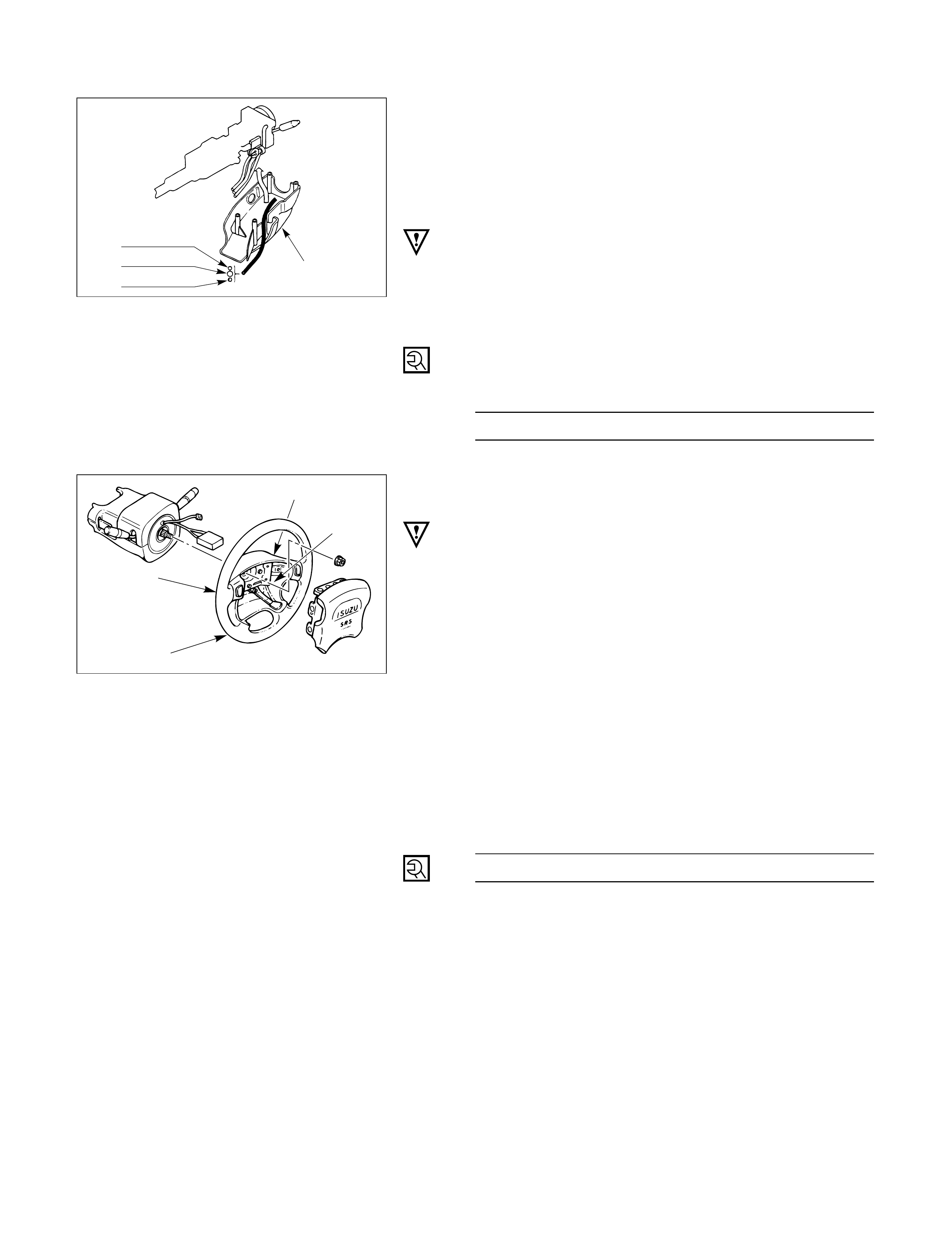
826RW027
Starter switch
harness
Combination
switch harness
Inflator module
harness
Setting cowl
(Lower)
6. Steering Column Cover
When installing the steering column cover, be sure to
route each wire harness as illustrated so that the
harnesses do not catch on any moving parts.
825RS048
5.Steering Wheel
Align the setting marks made when removing.
CAUTION:
Never apply force to the steering wheel in direction of the
shaft by using a hammer or other impact tools in an
attempt to remove the steering wheel. The steering shaft
is designed as an energy absorbing unit.
Tighten the steering wheel fixing nut to the specified
torque.
Steering Wheel Nut TorqueN·m (kg·m/lb·ft)
34 (3.5 / 25)
4.Inflator Module
1)Support the module and carefully connect the
module connector.
CAUTION:
•Never use the air bag assembly from another vehicle.
Use only the air bag assembly for "UBS".
•When replace the inflator module, use only same parts
number assembly. If different parts number assembly is
installed, the air bag system can not function correctly
because it has different characteristic.
NOTE:
Pass the lead wire through the tabs on the plastic
cover (wire protector) of inflator to prevent lead wire
from being pinched.
2)Secure the module with one bolt to relieve
weight on the connector wire.
3)Tighten bolts to specified sequence as figure.
Inflator Module Bolt TorqueN·m (kg·m/lb·in)
8 (0.8 / 69)
3.Steering Lower Cover
Install the engine hood opening lever.
2.Lower Cluster Assembly
1.Front Console Assembly
1)Install the transmission (for M/T) and transfer
control lever knob.
2)Install the wiring harness connectors.
Connect the battery ground cable.
Turn the ignition to "ON" while watching warning light.
Light should flash 7 times and then go off. If lamp
does not operate correctly, refer to Section 12M.
3
4
1
2
827RS017
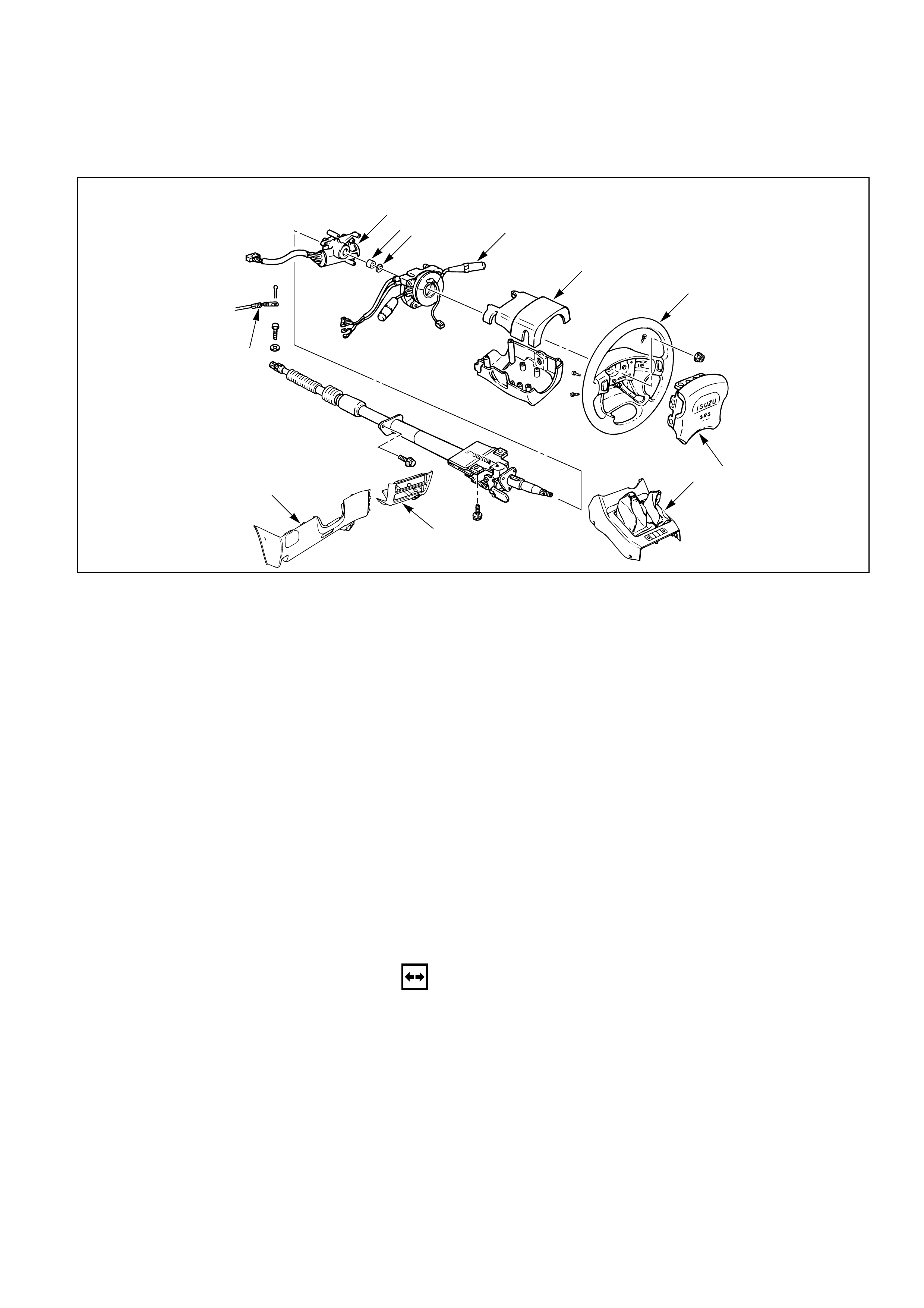
LOCK CYLINDER REPLACEMENT
1
5
4
6
7
8
9
11
10
3
2
Removal Steps
1. Front console assembly
2. Lower cluster assembly
3. Steering lower cover
4. Inflator module
5. Steering wheel
6. Steering column cover
7. Combination switch and
SRS coil assembly
8. Snap ring
9. Cushion rubber
10. Shift lock cable (for A/T)
11. Lock cylinder assembly
Installation Steps
11. Lock cylinder assembly
10. Shift lock cable (for A/T)
9. Cushion rubber
8. Snap ring
7. Combination switch and
SRS coil assembly
6. Steering column cover
5. Steering wheel
4. Inflator module
3. Steering lower cover
2. Lower cluster assembly
1. Front console assembly
431RT003
REMOVAL
Preparation:
1) Turn the steering wheel so that the vehicle's wheels
are pointing straight ahead.
2) Turn the ignition switch to "LOCK".
3) Disconnect the battery ground cable, and wait at least
5 minutes.
4) Disconnect the yellow 2way SRS connector located
under the steering column.
CAUTION:
The wheels of the vehicle must be straight ahead and the
steering column in the "LOCK" position before
disconnecting the steering wheel. Failure to do so will
cause the coil assembly to become uncentered which will
cause damage to the coil assembly.
1. Front Console Assembly
1) Remove the transmission (for M/T) and transfer
control lever knob.
2) Disconnect the wiring harness connectors.
2. Lower Cluster Assembly
3. Steering Lower Cover
Remove the engine hood opening lever.
4. Inflator Module
1) Loosen the inflator module fixing bolt from
behind the steering wheel assembly using a
TORXdriver or equivalent until the inflator
module can be released from steering assembly.
2) Disconnect the yellow 2way SRS connector
located behind the inflator module.
WARNING
THE INFLATOR MODULE SHOULD ALWAYS BE CARRIED
WITH THE URETHANE COVER AWAY FROM YOUR BODY
AND SHOULD ALWAYS BE LAID ON A FLAT SURFACE
WITH THE URETHANE SIDE UP. THIS IS NECESSARY
BECAUSE A FREE SPACE IS PROVIDED TO ALLOW THE
AIR CUSHION TO EXPAND IN THE UNLIKELY EVENT OF A
ACCIDENTAL DEPLOYMENT. OTHERWISE, PERSONAL
INJURY MAY RESULT.
827RT914
827RW037
827RS016
Up
5. Steering Wheel
Apply a setting mark across the steering wheel and
shaft so parts can be reassembled in their original
position.
Use special tool. Remove the steering wheel.
Move the tires to the straight ahead position before
removing the steering wheel.
Steering wheel remover: 5-8840-0016-0 (J-29752)
CAUTION:
Never apply force to the steering wheel in direction of
the shaft by using a hammer or other impact tools in an
attempt to remove the steering wheel. The steering
shaft is designed as an energy absorbing unit.
6. Steering Column Cover
7. Combination Switch and SRS Coil Assembly
1) Disconnect the wiring harness connectors
located under the steering column.
2) Remove the combination switch assembly with
SRS coil.
NOTE:
The SRS coil is a part of the combination switch
assembly, which can not be replaced separately.
Therefore, be sure not to remove the SRS coil from
the combination switch assembly.
8. Snap Ring
9. Cushion Rubber
10. Shift Lock Cable (for A/T)
11. Lock Cylinder Assembly
Disconnect the starter switch harness connector
located under the steering column.
825RS046
430RS004
430RW014
Setting mark
INSTALLATION
11. Lock Cylinder Assembly
10. Shift Lock Cable (for A/T)
9. Cushion rubber
8. Snap ring
7. Combination Switch and SRS Coil Assembly
1) After installation of combination switch
assembly, connect the combination switch
wiring harness connector and the SRS 2way
connector located under the steering column.
2) Turn the SRS coil counterclockwise to full, return
about 3 turns and align the neutral mark.
CAUTION:
When turning the SRS coil counterclockwise to full, stop
turning if resistance is felt. Forced further turning may
damage to the cable in the SRS coil.
6. Steering Column Cover
When installing the steering column cover, be sure to
route each wire harness as illustrated so that the
harnesses do not catch on any moving parts.
5. Steering Wheel
Align the setting marks made when removing.
CAUTION:
Never apply force to the setting wheel in direction of the
shaft by using a hammer or other impact tools in an
attempt to remove the steering wheel. The steering shaft
is designed as an energy absorbing unit.
Tighten the steering wheel fixing nut to the specified
torque.
Steering Wheel Nut Torque N·m (kg·m/lb·ft)
34 (3.5 / 25)
Alignment mark
826RW027
Starter switch
harness
Combination
switch harness
Inflator module
harness
Setting cowl
(Lower)
825RS048
3
4
1
2
4.Inflator Module
1)Support the module and carefully connect the
module connector.
CAUTION:
•Never use the air bag assembly from another vehicle.
Use only the air bag assembly for "UBS".
•When replace the inflator module, use only same parts
number assembly. If different parts number assembly is
installed, the air bag system can not function correctly
because it has different characteristic.
NOTE:
Pass the lead wire through the tabs on the plastic
cover (wire protector) of inflator to prevent lead wire
from being pinched.
2)Secure the module with one bolt to relieve
weight on the connector wire.
3)Tighten bolts to specified sequence as figure.
Inflator Module Bolt TorqueN·m (kg·m/lb·in)
8 (0.8 / 69)
3.Steering Lower Cover
Install the engine hood opening lever.
2.Lower Cluster Assembly
1.Front Console Assembly
Connect the wiring harness connectors.
Install the transmission (for M/T) and transfer control
lever knob.
Connect the yellow 2way SRS connector located
under the steering column.
Connect the battery ground cable.
827RS017
SYSTEM INSPECTION
•Turn the ignition to "ON" while watching
warning light.
•Light should flash 7 times and then go off. If
lamp does not operate correctly, refer to Section 12M.
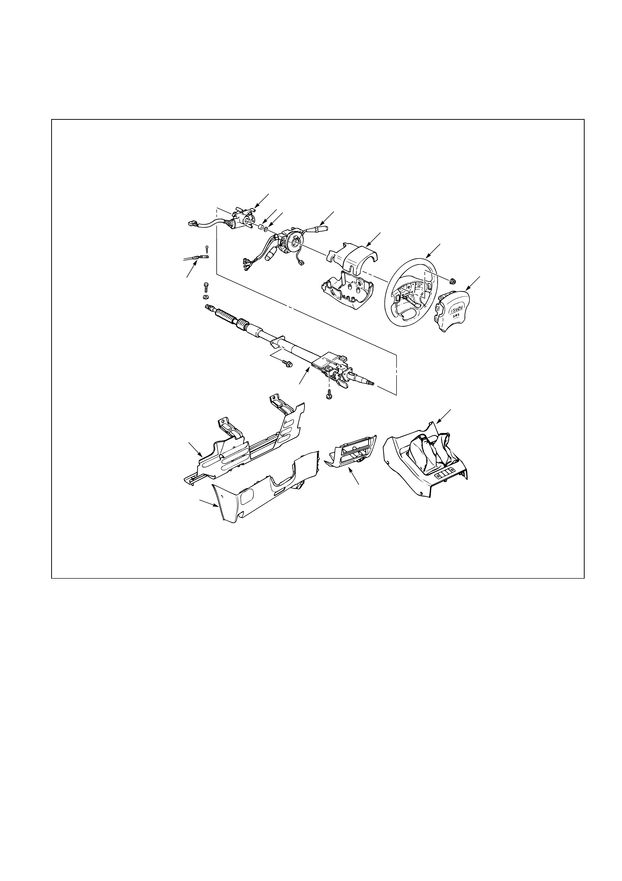
STEERING COLUMN REPLACEMENT
12
10 98
7
5
6
11
2
13
4
3
1
Removal Steps
1. Front console assembly
2. Lower cluster assembly
3. Steering lower cover
4. Driver knee bolster (rein-
forcement)
5. Inflator module
6. Steering wheel
7. Steering column cover
8. Combination switch and
SRS coil assembly
9. Snap ring
10. Cushion rubber
11. Shift lock cable (for A/T)
12. Lock cylinder assembly
13. Steering column assembly
Installation Steps
13. Steering column assembly
12. Lock cylinder assembly
11. Shift lock cable (for A/T)
10. Cushion rubber
9. Snap ring
8. Combination switch and
SRS coil assembly
7. Steering column cover
6. Steering wheel
5. Inflator module
4. Driver knee bolster (reinforcement)
3. Steering lower cover
2. Lower cluster assembly
1. Front console assembly
REMOVAL
Preparation:
1) Turn the steering wheel so that the vehicle's wheels
are pointing straight ahead.
2) Turn the ignition switch to "LOCK".
3) Disconnect the battery ground cable, and wait at least
5 minutes.
4) Disconnect the yellow 2way SRS connector located
under the steering column.
CAUTION:
The wheels of the vehicle must be straight ahead and the
steering column in the "LOCK" position before
disconnecting the steering wheel.
Failure to do so will cause the SRS coil assembly to
become uncentered which will cause damage to the SRS
coil assembly.
1. Front Console Assembly
Disconnect the transmission (for M/T) and transfer
control lever knob.
Disconnect the wiring harness connectors.
2. Lower Cluster Assembly
3. Steering Lower Cover
Remove the engine hood opening lever.
4. Driver Knee Bolster (Reinforcement)
5. Inflator Module
1) Loosen the inflator module fixing bolt from
behind the steering wheel assembly using a
TORXdriver or equivalent until the inflator
module can be released from steering assembly.
2) Disconnect the yellow 2way SRS connector
located behind the inflator module.
827RT914
827RW037
WARNING
THE INFLATOR MODULE SHOULD ALWAYS BE CARRIED
WITH THE URETHANE COVER AWAY FROM YOUR BODY
AND SHOULD ALWAYS BE LAID ON A FLAT SURFACE
WITH THE URETHANE SIDE UP. THIS IS NECESSARY
BECAUSE A FREE SPACE IS PROVIDED TO ALLOW THE
AIR CUSHION TO EXPAND IN THE UNLIKELY EVENT OF A
ACCIDENTAL DEPLOYMENT. OTHERWISE, PERSONAL
INJURY MAY RESULT.
6. Steering Wheel
Apply a setting mark across the steering wheel and
shaft so parts can be reassembled in their original
position.
Use special tool. Remove the steering wheel.
Move the tires to the straight ahead position before
removing the steering wheel.
Steering wheel remover: 5-8840-0016-0 (J-29752)
7. Steering Column Cover
8. Combination Switch and SRS Coil Assembly
1) Disconnect the wiring harness connectors
located under the steering column.
2) Remove the combination switch assembly with
SRS coil.
NOTE:
The SRS coil is a part of the combination switch
assembly, which can not be replaced separately.
Therefore, be sure not to remove the SRS coil from
the combination switch assembly.
9. Snap Ring
10. Cushion Rubber
11. Shift Lock Cable (for A/T)
12. Lock Cylinder Assembly
Disconnect the starter switch harness connector
located under the steering column.
827RS016
825RS046
Up
430RS004
430RW014
Setting mark
Setting mark
13. Steering Column Assembly
Apply a setting mark across the universal joint and
steering shaft to reassemble the parts in their original
position.
NOTE:
A setting mark can be easily made if the shaft is
withdrawn a little by loosening the steering shaft
universal joint.
431RV003
INSTALLATION
13. Steering Column Assembly
Align the setting marks on the universal joint and
steering shaft made during removal.
Tighten the steering column fixing bolt (dash panel)
to the specified torque.
Steering Column Bolt Torque N·m (kg·m/lb·ft)
19 (1.9 / 14)
Tighten the steering column fixing bolt (pedal
bracket) to the specified torque.
Steering Column Bolt Torque N·m (kg·m/lb·ft)
17 (1.7 / 13)
Tighten the universal joint to the specified torque.
Universal Joint Torque N·m (kg·m/lb·ft)
25 (2.5 / 18)
12. Lock Cylinder Assembly
11. Shift Lock Cable (for A/T)
10. Cushion Rubber
9. Snap Ring
8. Combination Switch
1) After installation of combination switch
assembly, connect the combination switch
wiring harness connector and the SRS 2way
connector located under the steering column.
2) Turn the SRS coil counterclockwise to full, return
about 3 turns and align the neutral mark.
CAUTION:
When turning the SRS coil counterclockwise to full, stop
turning if resistance is felt. Forced further turning may
damage to the cable in the SRS coil.
Alignment mark
826RW027
Starter switch
harness
Combination
switch harness
Inflator module
harness
Setting cowl
(Lower)
7. Steering Column Cover
When installing the steering column cover, be sure to
route each wire harness as illustrated so that the
harnesses do not catch on any moving parts.
6. Steering Wheel
Align the setting marks made when removing.
CAUTION:
Never apply force to the steering wheel in direction of the
shaft by using a hammer or other impact tools in an
attempt to remove the steering wheel. The steering shaft
if designed as an energy absorbing unit.
Tighten the steering wheel fixing nut to the specified
torque.
Steering Wheel Nut Torque N·m (kg·m/lb·ft)
34 (3.5 / 25)
5. Inflator Module
1) Support the module and carefully connect the
module connector.
CAUTION:
•Never use the air bag assembly from another vehicle.
Use only the air bag assembly for "UBS".
•When replace the inflator module, use only same parts
number assembly. If different parts number assembly is
installed, the air bag system can not function correctly
because it has different characteristic.
NOTE:
Pass the lead wire through the tabs on the plastic
cover (wire protector) of inflator to prevent lead wire
from being pinched.
2) Secure the module with one bolt to relieve
weight on the connector wire.
3) Tighten bolts to specified sequence as figure.
Inflator Module Bolt Torque N·m (kg·m/lb·in)
8 (0.8 / 69)
4 Driver Knee Bolster (Reinforcement)
3. Steering Lower Cover
Install the engine hood opening lever.
2. Lower Cluster Assembly
1. Front Console Assembly
Connect the wiring harness connectors.
Install the transmission (for M/T) and transfer control
lever knob.
Connect the yellow 2way SRS connector located
under the steering column.
Connect the battery ground cable.
825RS048
3
4
1
2
827RS017