
Audio Installation Guide - Monterey
ATTACHMENT TO ENGINEERING BULLETIN _______________
Eurovox Kit: 92074559 Page: 1 of 5
KIT CONTENTS:
ITEM EUROVOX PART NUMBER
1.
RADIO CASSETTE MOD8491IS1
2.
RADIO HARNESS KDH-013
3.
SPEAKERS 4” - REAR DOOR (2) W/GRILLES 2041/BL
4.
SPEAKERS 4” - REAR (2) ETS502CX
5.
SPEAKERS 6” - FRONT DOOR (2) 2067C/BL
6.
ANTENNA MOD53IS1
7.
ANTENNA MODULE MOD9494IS2
8.
HANDBOOK HPB-8490/1V
EXTRAS:
CABLE TIES STD (6) 6 x 10 HEX HEAD BOLTS (2) 6mm NUT
CABLE TIES LGE (2) SECURITY CODE CARD 10g x ¾” SCREWS (8)
INSTALLATION PROCEDURES:
CAUTION: Fit 20 AMP audio fuse before commencing (Position C15)
FRONT DOOR SPEAKERS
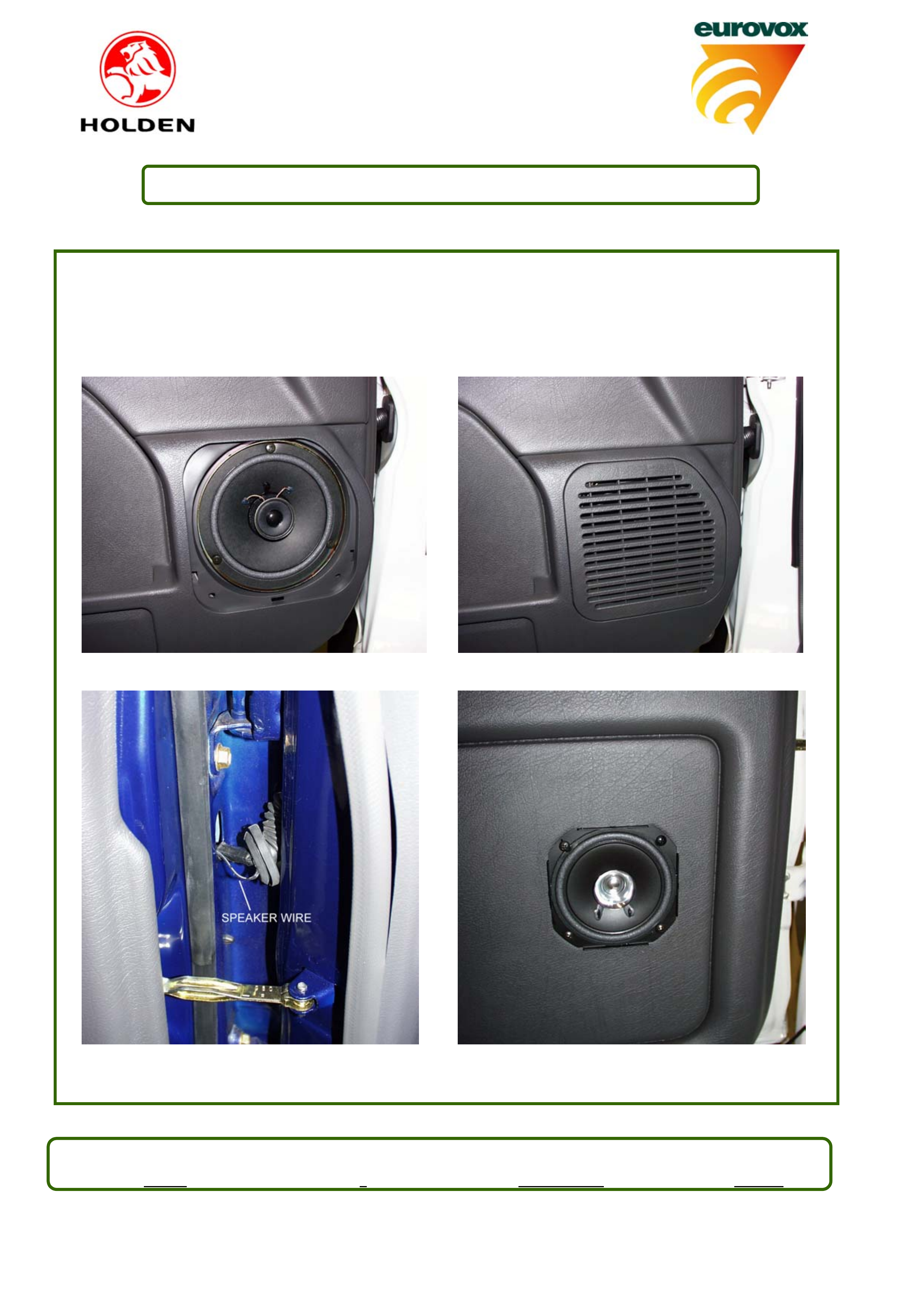
1. Remove door speaker cover (via clips) and speaker blank (3 screws). Discard blanking plate.
2. Locate vehicle harness and plug into speaker. Mount 6” speaker, using original screws [Fig A] and
refit door cover [Fig B]. Repeat for other front door.
REAR DOOR SPEAKERS
3. Remove front and rear floor sill panels and kick trim.
4. Remove door seal rubbers from centre pillar cover and remove cover [clips].
5. Using template provided, mark speaker locations and cut speaker hole.
FOR MODEL 8DQ 35
Remove grommet seals and use grommets provided between door and body.
6. Feed speaker lead through hole in centre pillar and into door via cable grommet [Fig C] to speaker
hole. Cut hole at door end of grommet. NOTE: Ensure that wires feed behind window guide.
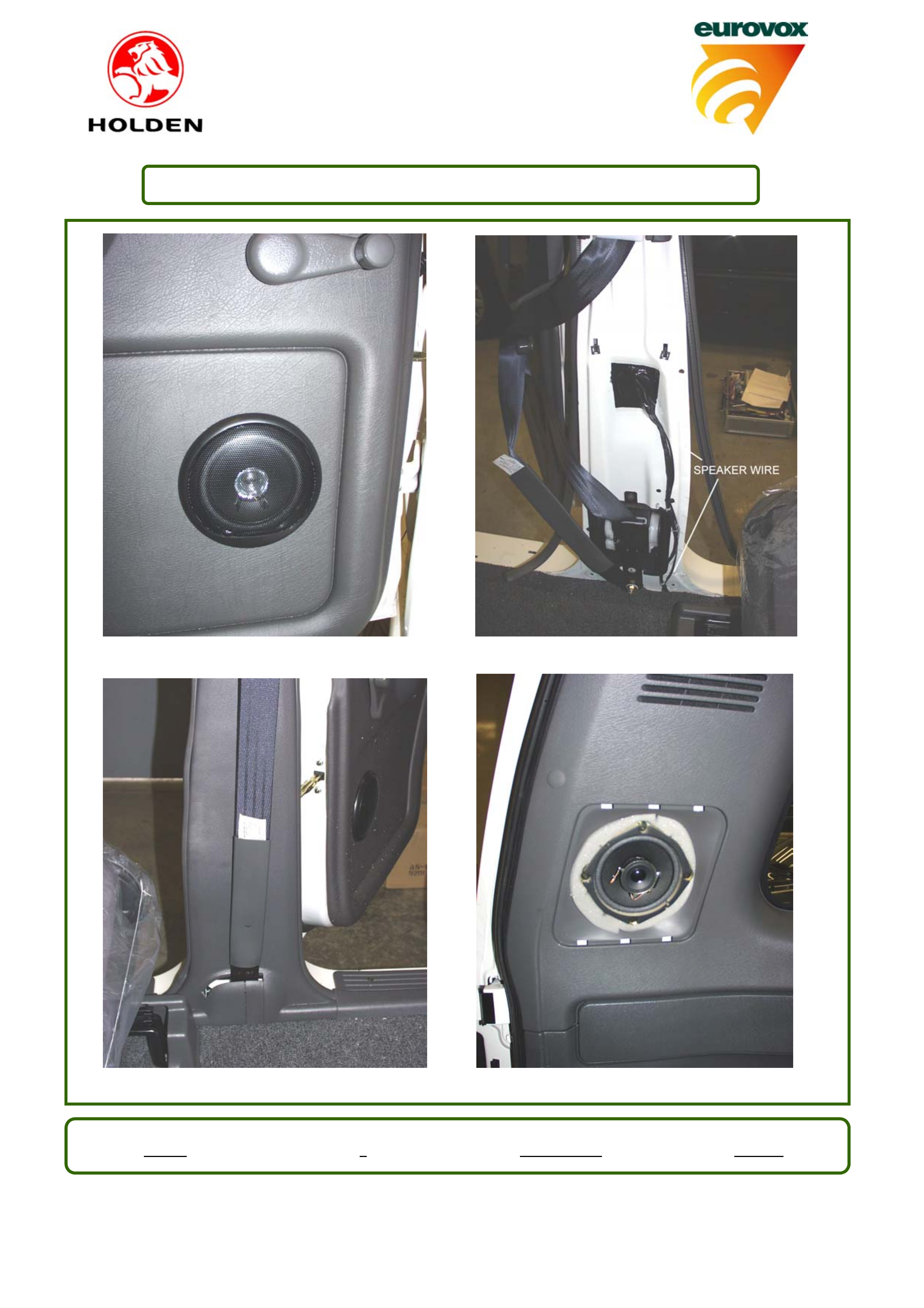
7. Connect wires to speaker and mount speaker using 4 screws provided [Fig D]. Fit speaker grille
[Fig E].
8. Feed wires from centre pillar to floor (cable tie to existing wiring)[Fig F]. Continue under carpet to
kick panel.
9. Refit centre pillar cover, door seals, floor sill panels and kick trim [Fig G]. Leave passenger side kick
trim off. (IF INSTALLING CD CHANGER TO MONTEREY, PERFORM THIS STEP AFTER INSTALLING CD CHANGER)
10. Repeat for other door
Eurovox No. Issue No. Authorised Date
EIG089 3Colin Moreland 10/12/01
Audio Installation Guide
92074559 - MONTEREY Page: 2 of 5
REAR SPEAKERS
11. Remove speaker cover (via clips) and speaker blank (4 screws). Discard blanking plate.
12. Locate vehicle harness and plug into speaker. Mount 4” speaker, using original screws [Fig H] and
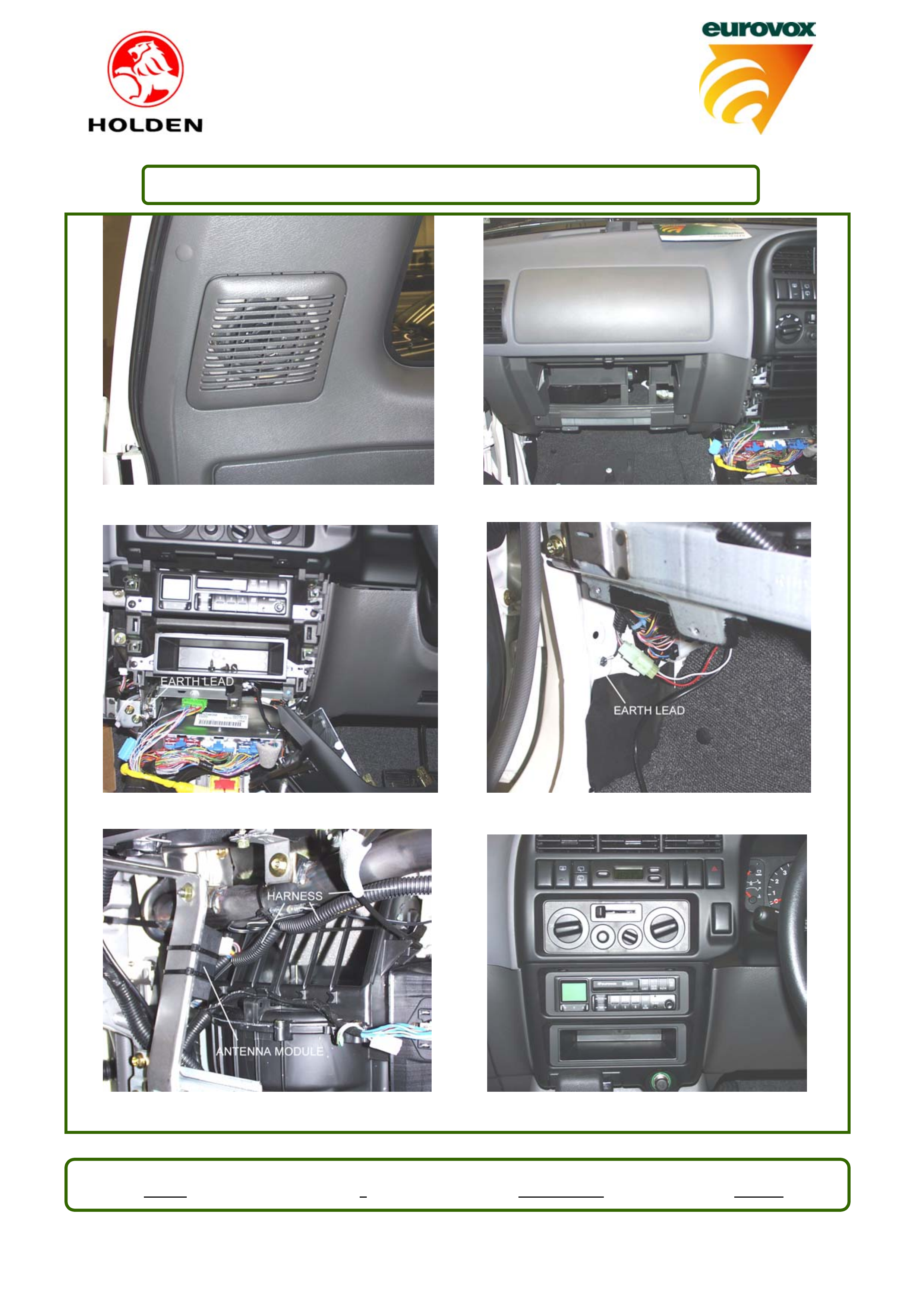
refit cover [Fig I]. Repeat for other speaker.
ANTENNA
13. Fully turn wheel to left lock.
14. Remove inner guard liner (8 screws and 3 clips)
15. Remove head kit from antenna, leaving aluminium base plate.
16. Mount antenna, via bracket, using 6 X 10 bolt provided.
17. Remove grommet and discard. Feed power cable, then antenna lead through hole and fit grommet.
18. Mount head kit and refit inner guard.
19. Remove centre console (4 screws).
20. Remove radio surround (3 screws and clips).
21. Remove 2 screws securing right hand dash panel.
22. Remove glove box and left-hand dash panel (7 screws and clips) [Fig J].
23. Remove top pocket (2 screws) and discard pocket.
24. Connect antenna power lead to harness and mount earth, via 6 X 10 bolt, to body [Fig L].
25. Plug antenna module into harness and mount module to frame using cable ties [Fig M].
26. Route harness to radio cavity. Connect speaker lead to rear door speaker lead (blue wire
connection).
CD PLAYER (SE MODEL)
Refer to Installation guide EIG112 (Kit # 92074558). Steps 4, 6 - 8.
CD CHANGER (MONTEREY)
Refer to Installation guide EIG109 (Kit # 92074559). Steps 7 – 14.
RADIO
27. Locate vehicle harness and antenna lead. Connect radio harness to vehicle harness. Feed speaker
wire (yellow wire connection) to drivers side and connect to rear door speaker lead. Cable tie
speaker lead to existing wiring in 2 positions.
28. Plug harness and antenna lead into rear of unit and mount unit using original pocket screws. Ensure
that earth lead feeds behind and below bottom pocket. Connect earth lead to bolt using 6mm nut
provided [Fig K].
Eurovox No. Issue No. Authorised Date
EIG089 3Colin Moreland 10/12/01
Audio Installation Guide
92074559 - MONTEREY Page: 2 of 5
29. Refit passenger side kick trim and left hand dash panel. Refit glovebox.
30. Refit 2 screws for right hand dash panel and refit radio surround. Refit centre console[Fig N].
31. Enter security code and test all functions.
FIGURE A FIGURE B
FIGURE C FIGURE D
Eurovox No. Issue No. Authorised Date
EIG089 3Colin Moreland 10/12/01
Audio Installation Guide
92074559 - MONTEREY Page: 2 of 5
FIGURE E FIGURE F
FIGURE G FIGURE H
Eurovox No. Issue No. Authorised Date
EIG089 3ColinMoreland 10/12/01
Audio Installation Guide
92074559 - MONTEREY Page: 2 of 5
FIGURE I FIGURE J
FIGURE K FIGURE L
FIGURE M FIGURE N
Eurovox No. Issue No. Authorised Date
EIG089 3Colin Moreland 10/12/01