General Information Page 0A–1
Page 0A–1
Section 0A
General Information
ATTENTION
Before performing any Service Operation or other procedure described in this Section, refer to Section 00
Warnings, Cautions and Notes for correct workshop practices with regard to safety and/or property damage.
1 General Information ...............................................................................................................................2
1.1 Hoist Pad Locations .............................................................................................................................................. 3
2 Model Availability and Equipment........................................................................................................4
3 Major Option Codes ...............................................................................................................................5
4 Powertrain...............................................................................................................................................6
5 Engine Data.............................................................................................................................................7
6 Transmission Data .................................................................................................................................8
7 Transfer Case Data.................................................................................................................................9
8 Exterior Dimensions ............................................................................................................................10
9 Vehicle Weights....................................................................................................................................11
10 Fuel Consumption Label .....................................................................................................................12
11 Serial Numbers.....................................................................................................................................13
11.1 Vehicle Identification Numbering System ......................................................................................................... 13
11.2 Automatic Transmission Serial Number............................................................................................................ 14
11.3 Transfer Case Assembly Serial Numbers.......................................................................................................... 15
11.4 Front Final Drive .................................................................................................................................................. 16
11.5 Rear Final Drive.................................................................................................................................................... 17
12 Special Tools ........................................................................................................................................18
Transfer Case....................................................................................................................................................... 19
Front Suspension ................................................................................................................................................ 20
Front Final Drive .................................................................................................................................................. 21
Rear Suspension.................................................................................................................................................. 22
Techline
Techline
Techline
Techline
Techline
Techline

General Information Page 0A–2
Page 0A–2
1 General Information
The MY 2004 All Wheel Driv e (AWD) Adventra Wagon is a new variant of the five door wagon body style in the Holden
Commodore range. It is a constant AWD vehicle and is available only with the GEN III V8 engine and 4L60-E automatic
transmission.
The CX8 model is Berlina based, but with some sports oriented finishes. The LX8 model variant adopts some MY 2004
VY Calais style interior finishes.
The main features and changes for the MY 2004 AWD Wagon Series are summarised in the following list:
• Constant all wheel drive ‘Cross T rac’ powertrain.
• Heavy duty front and rear sus pension to suit All Wheel Drive applicati on.
• Heavy duty engin e cooling fan system.
• All wheel traction control system (Automatic Brake Differential – ABD) to suit AWD application.
• Front to rear brake proportioning using Electronic Brake-force Distribution (EBD) under heavy braking.
• Climate Control fitted as standard, single zone on CX8 models and dual zone on L X 8 models.
• Visual ice warning via Climate Control display.
• Unique front and rear facia.
• Extension mouldings on front and rear wheelhouses.
• New bodyside mouldings.
• New endgate configuratio n with a separate opening rear window glass.
• 1600 kg capacity tow bar mount.
• New rear roof air deflector including LED high mounte d stop lamp.
• New style roof racks with cross bars option.
• Exterior colour range of eight colo urs, all from MY 2004 VY Series.
• Ochre or Black Anthracite leather interior trims available for LX8 models.
• Neutral Pewter cloth (standard) or leather (optional) for CX8 models.
• SS style front seats for LX8 models.
• Eight way electric seats with memory function and memory mirrors for LX8 models.
• Electric sliding sunroof and roof luggag e carrier – On line fitment for LX8 standard, CX8 optional.
• Interior load tie-down rails and hooks (with stowaway cargo net for LX8 models).
• MY 2004 VY style interior finishes:
• Leather covered, satin chrome gear kn ob and park brake handle.
• Leather covered steering wheel (with sports profile on LX8) and optional a lloy pedals.
• Additional instrumentation (in cli nometer) on top centre of instrument panel area for LX8 mode ls.
• New badging to denote AWD and mo del level.
• Reverse parking aid (first usage on a wagon).
• 17" wheels and tyres.
• Tow points accessed (using towing eye supplied) through port on front and rear fascias.
• Cruise control.
• Steering wheel mounted audio controls (illuminated on LX8).
• Audio system with six disc ‘in dash’ CD player incorporating:
• Six speakers and 60 Watts for CX8 models.
• Premium sound with seven speakers, subwoofer and 200 Watts for LX8 models.
General Information Page 0A–3
Page 0A–3
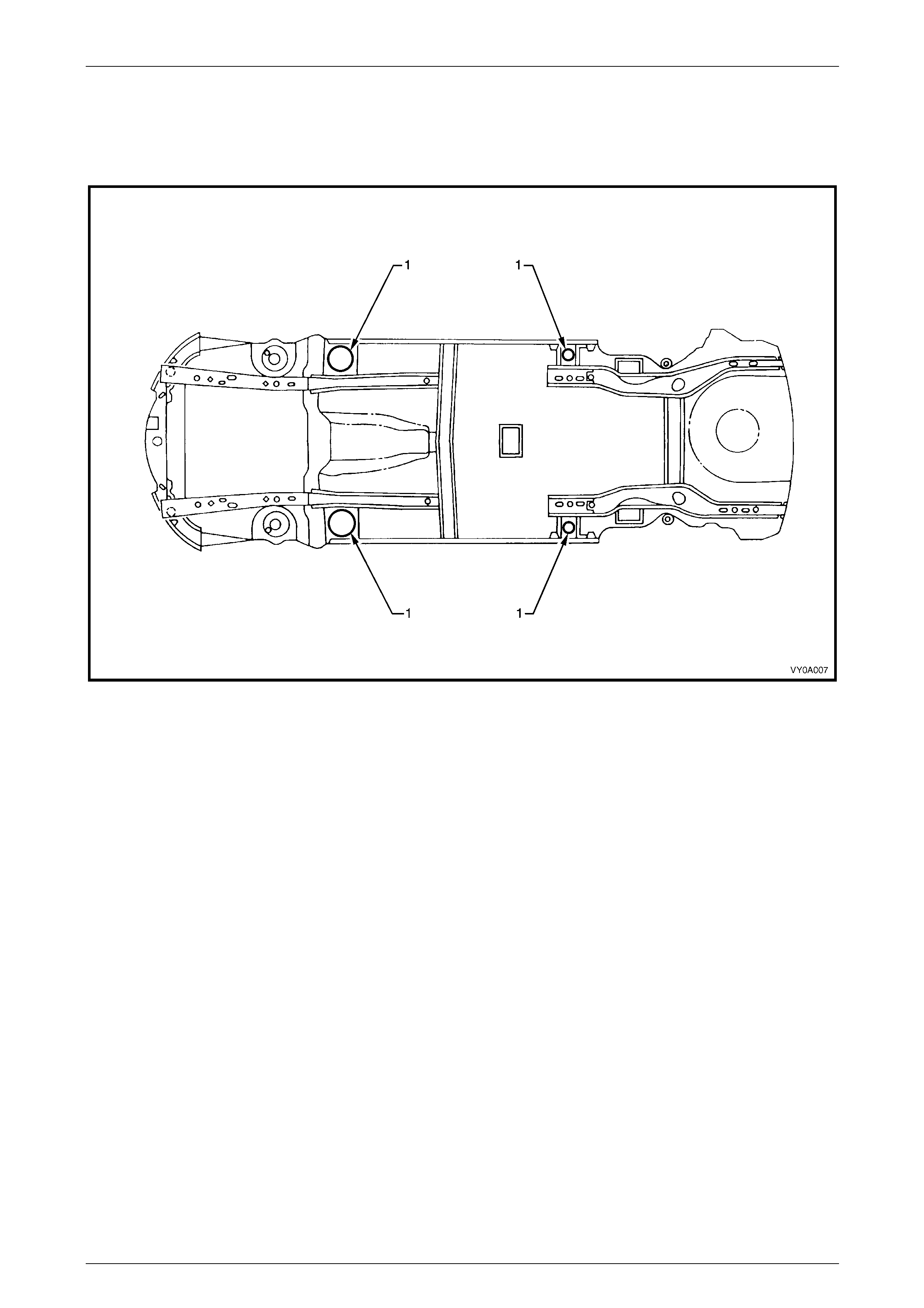
1.1 Hoist Pad Locations
When using a trolle y jack to raise the vehicle, it is important that the jack be positioned un der the suspension cross
member or hoist pad (1) locations. Do not jack under the suspension control arm. The vehicle should always be
supported by jack stands at the hoist pad locations when raised.
Figure 0A – 1
General Information Page 0A–4
Page 0A–4
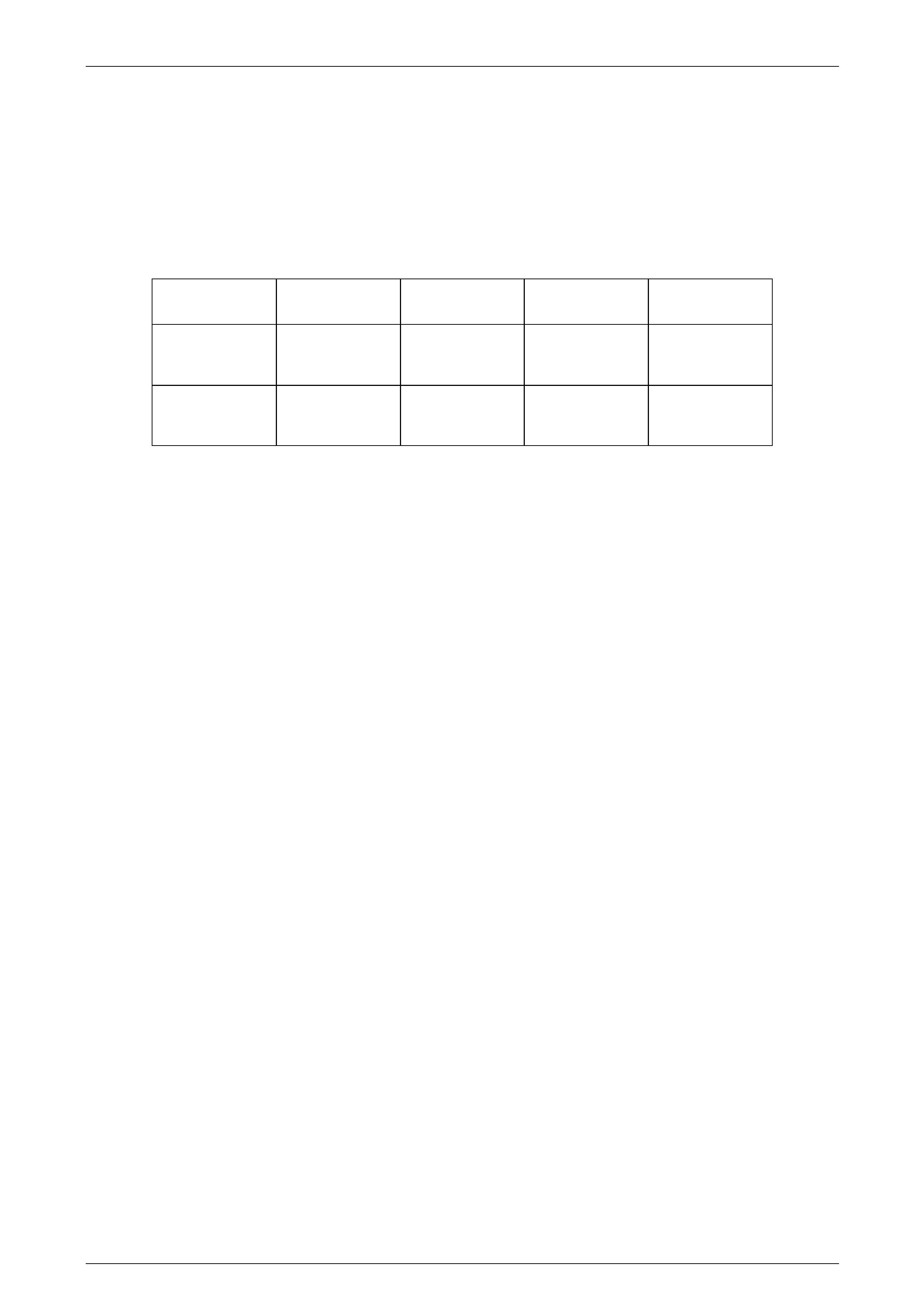
2 Model Availability and
Equipment
NOTE
For tyre and wheel information, refer to
Section 10 Wheels and Tyres in this Service
Information.
Model Name Luxury Level
(Description) Model Code. Body Style
(Doors) Engine
Adventra CX8 Low Level
(Sport) 8VM35 Wagon (5) V8
Adventra LX8 High Level
(Luxury Sports) 8VM35 & YC3 Wagon (5) V8
General Information Page 0A–5
Page 0A–5
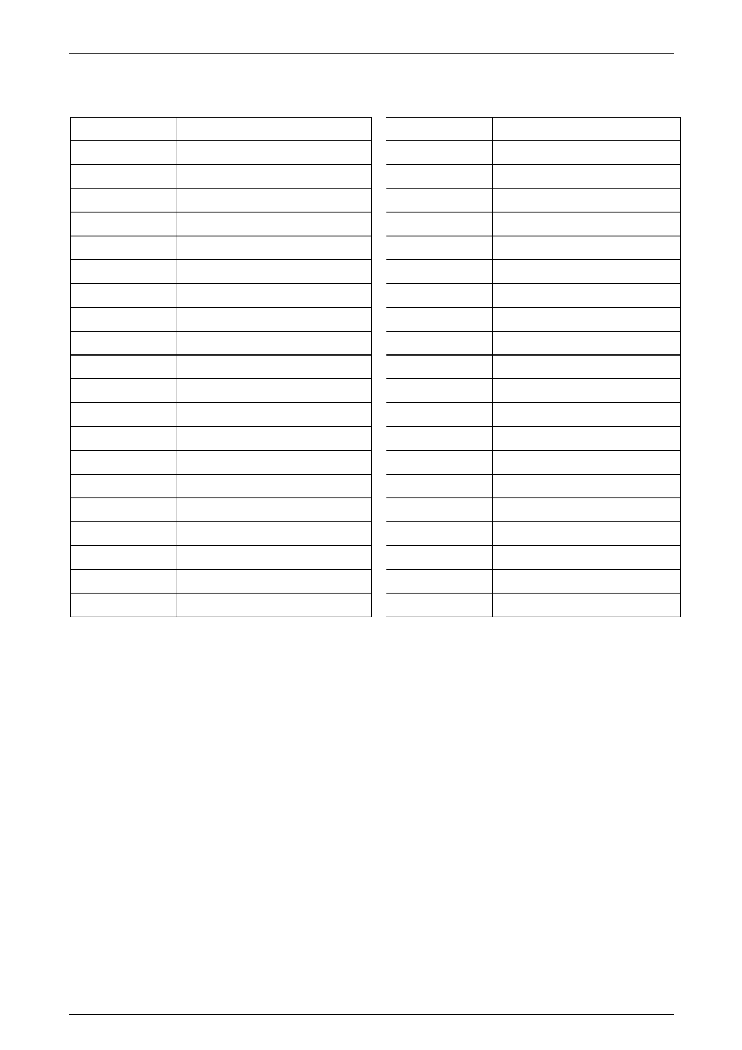
3 Major Option Codes
Option Code Description Option Code Description
A31 Power Windows (Front and Rear) N46 Steering Wheel 4 Spokes
AG3 Memory Driver’s Seat N88 7.5 JJ x17" Alloy wheel (XLS)
AH6 Driver’s Seat, 4 Way N93 7.5 JJ x17" Alloy wheel (XS)
AH8 Passenger Seat, 8 Way NK4 Sports Leather Steering Wheel
AJ7 Side Impact Air Bag NW9 Traction Control (with ABS)
AQ9 Front Seat, Reclining Bucket QBB 225/55 R17 97H Tyre
B58 Mats in anthracite with suede trim R5C Bridgestone Hybrid Tyre Desi gn
C61 Automatic Air Conditioning U08 Dual Note Horns
CC5 Sunroof – Factory Fitted U1V Audio System, 60W 6 Disk CD
CJ2 Dual Zone Air Conditioning U1X Audio System, 260W 6 Disk CD
D42 Retracting Roller Cargo Blin d U75 Antenna, Power
FE1 Suspension – Soft Ride UD7 Reverse Parking Aid
FX3 Suspension – Level Ride UE1 Holden Assist
GS9 Axle, 3.46:1 Ratio Rear UJ8 Instrument Cluster
JL9 Anti-Lock Brake System VDQ Roof Luggage Carrier
K30 Cruise Control W1Y Steering Wheel Radio Controls
K69 Keys, Additional Set XS4 Roo Bar
LS1 235KW, 5.7 V8 EFI Petrol Engine XW6 Paint, Metallic Finish
MK2 Transmission, 4 Speed Automatic YC3 High Series Package
N40 Power Steering
General Information Page 0A–6
Page 0A–6
4 Powertrain
Component Designation / ID Code Type
Engine GEN III V8 V8 5.7 litre OHV PFI
Transmission 4L60-E 4 speed with Overdrive
Transfer Case NV124 Full time AWD, Gear Drive
Final Drive – Front DY Conventional, Ratio – 3.46:1
Final Drive – Rear SB Conventional, Ratio – 3.46:1
General Information Page 0A–7
Page 0A–7
5 Engine Data
Engine Designation GEN III V8
Piston Displacement
Nominal – cm3 5667
Compression Ratio 10.1:1
Number of Cylinders 8
Bore x Stroke – mm 99 X 92
Taxable H.P.
RAC OR SAE 48.6
Power kW
DIN @ RPM 235 kW @ 5200
Torque Nm
DIN @ RPM 465 Nm @ 4400
General Information Page 0A–8
Page 0A–8
6 Transmission Data
Model 4L60-E
Torque converter 4 element (including lock- up clutch)
Pump 13 Vane, variable displacement
No. of clutch packs 5
No. of bands 1
No. of planetary gear sets 2
No. of solenoids 6
No. of electrical sensors 3
Ratios:
1st
2nd
3rd
4th
Reverse
3.06:1
1.63:1
1.00:1
0.70:1
2.29:1
General Information Page 0A–9
Page 0A–9
7 Transfer Case Data
Manufacturer New Venture Gear (NVG)
Model NV124
Type Full Time AWD
Torque Split 38 / 62 per cent, front to rear
General Information Page 0A–10
Page 0A–10
8 Exterior Dimensions
Body Dimensions (mm) CX8 LX8
Vehicle length 5036
Vehicle width (exclu ding moulding) 1934
Vehicle height 1651
Wheelbase 2948
Overhang – front 931
Overhang – rear 1158
Track – front 1617
Track – rear 1623
General Information Page 0A–11
Page 0A–11
9 Vehicle Weights
Vehicle Weights (kg) CX8 LX8
Kerb mass 1940 1983
Rear axle load 1300
Payload (5 passengers plus cargo) 480
NOTE
Payload figures include luggage, goods,
passengers, roof rack load and a full tank of fuel.
When towing, the weight on the tow bar bal l must
also be included.
NOTE
Maximum rear axle load is the maximum for all
conditions.
General Information Page 0A–12
Page 0A–12
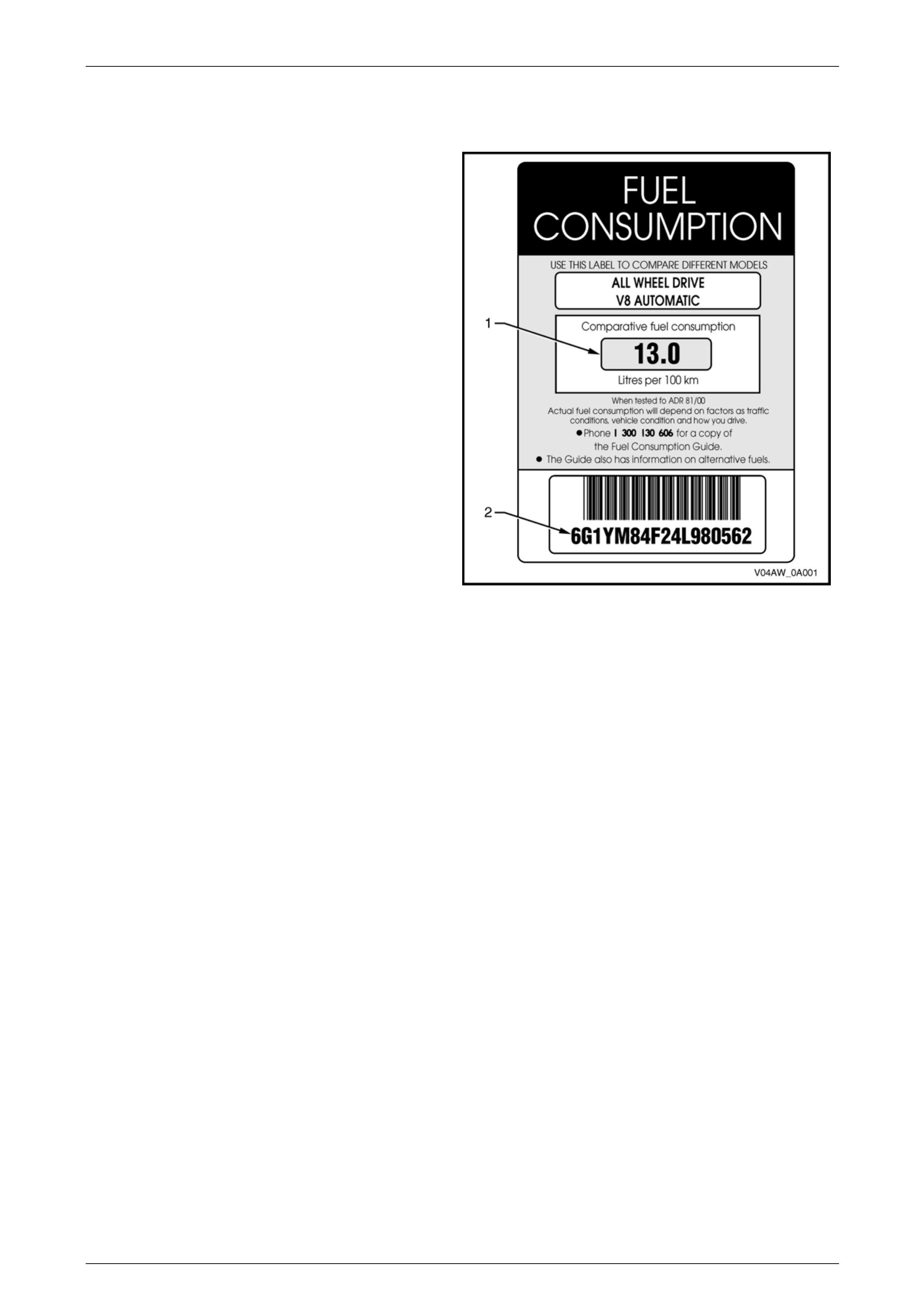
10 Fuel Consumption Label
ADR 81/00 required that from 1 January 2001, a label
similar to that shown in Figure 0A – 2, is attached to the
windscreen of any new domestic vehicle which is displayed
for sale.
The fuel consumption labe l figures (1) quoted are the
results of tests carried out in accordance with the City
Cycle test procedure of AS2877 – 19 86, an Australian
standard for fuel consumption testing. Each vehicle is
tested under identical conditions. T he tests therefore
enable a comparison to be made between vehicles.
The label should be removed from the windscreen
immediately prior to the vehicle being delivered to the
owner.
The number on the lower portion of the label (2) should
match the Vehicle Identification Numb er.
Figure 0A – 2
General Information Page 0A–13
Page 0A–13
11 Serial Numbers
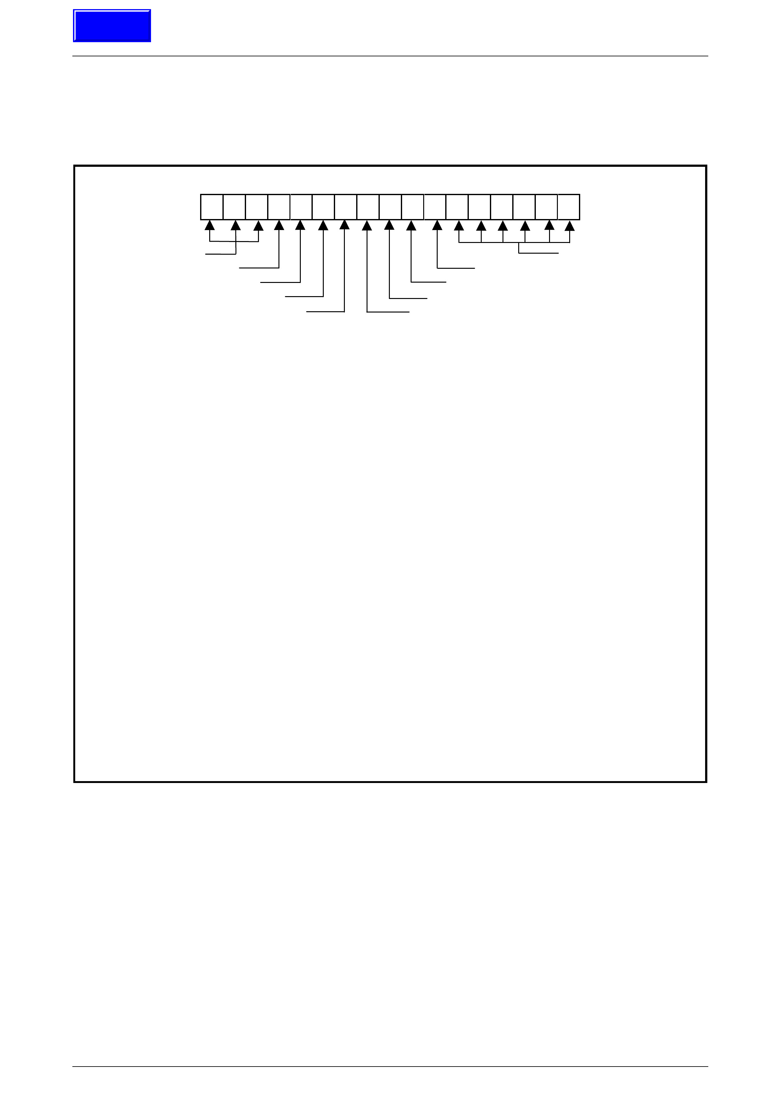
11.1 Vehicle Identification Numbering System
6 G 1 Y M 8 4 F 0 4 L 1 2 3 4 5 6
WMI CODE PRODUCTION
CARLINE PLANT SEQUENCE NUMBER
LUXURY LEVEL MODEL YEAR
BODY STYLE VIN CHECK DIGIT
RESTRAINT CODE ENGINE TYPE
WMI CODE: 6 – Oceania
G – Australia
1 – Holden
CARLINE: Y – VY Series
LUXURY LEVEL: M – CX8
M – LX8
BODY STYLE: 8 – 5 door station wagon (35)
RESTRAINT CODE: 4 – Active (manual) seat belts with driver and passenger inflatable restraint
system – frontal and side
ENGINE TYPE: F – 5.7 litre GEN III V8 engine
VIN CHECK DIGIT: Calculated check digit
MODEL YEAR: 4 – 2004
PLANT: L – Adelaide (Elizabeth) South Australia
PRODUCTION SEQUENCE NUMBER:
123456 – Sequential Production Serial Number
NOTE
The production sequence number is sequentially allocated to each vehicle, regardless of vehicle type.
Figure 0A – 3
Techline
General Information Page 0A–14
Page 0A–14
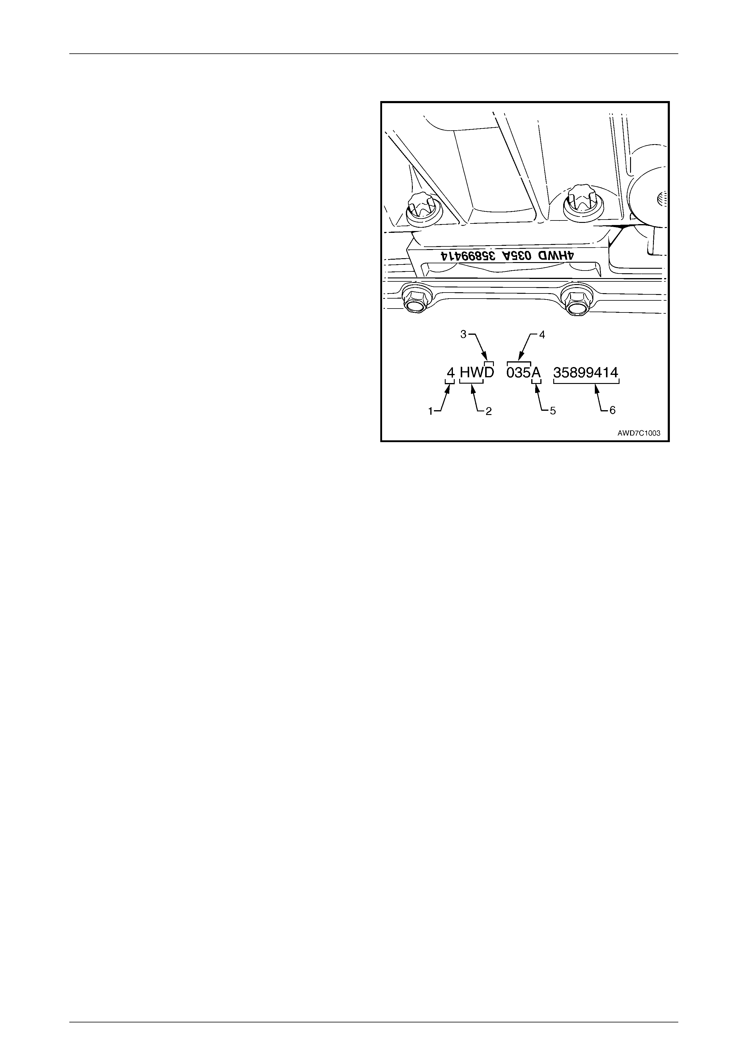
11.2 Automatic Transmission Serial Number
The automatic transmission serial number is stamped into
a machined surface located a t the rear underside of the
transmission centre case, between the rear ext ension
housing and the transmission fluid pan.
Legend
1 Model Year (‘4’ = 2004)
2 Model: AWD Wagon and 5.7 litre GEN III V8 – 'HW'
3 Transmission Model Identifier (‘D’ = 4L60-E)
4 Julian Date (Day of the Year)
5 Shift Build ‘A’, ‘B’, ‘J’ = First Shift;
‘C’, ‘H’, ‘W’ = Second Shift
6 Individual Transmission Serial Number
Figure 0A – 4
General Information Page 0A–15
Page 0A–15
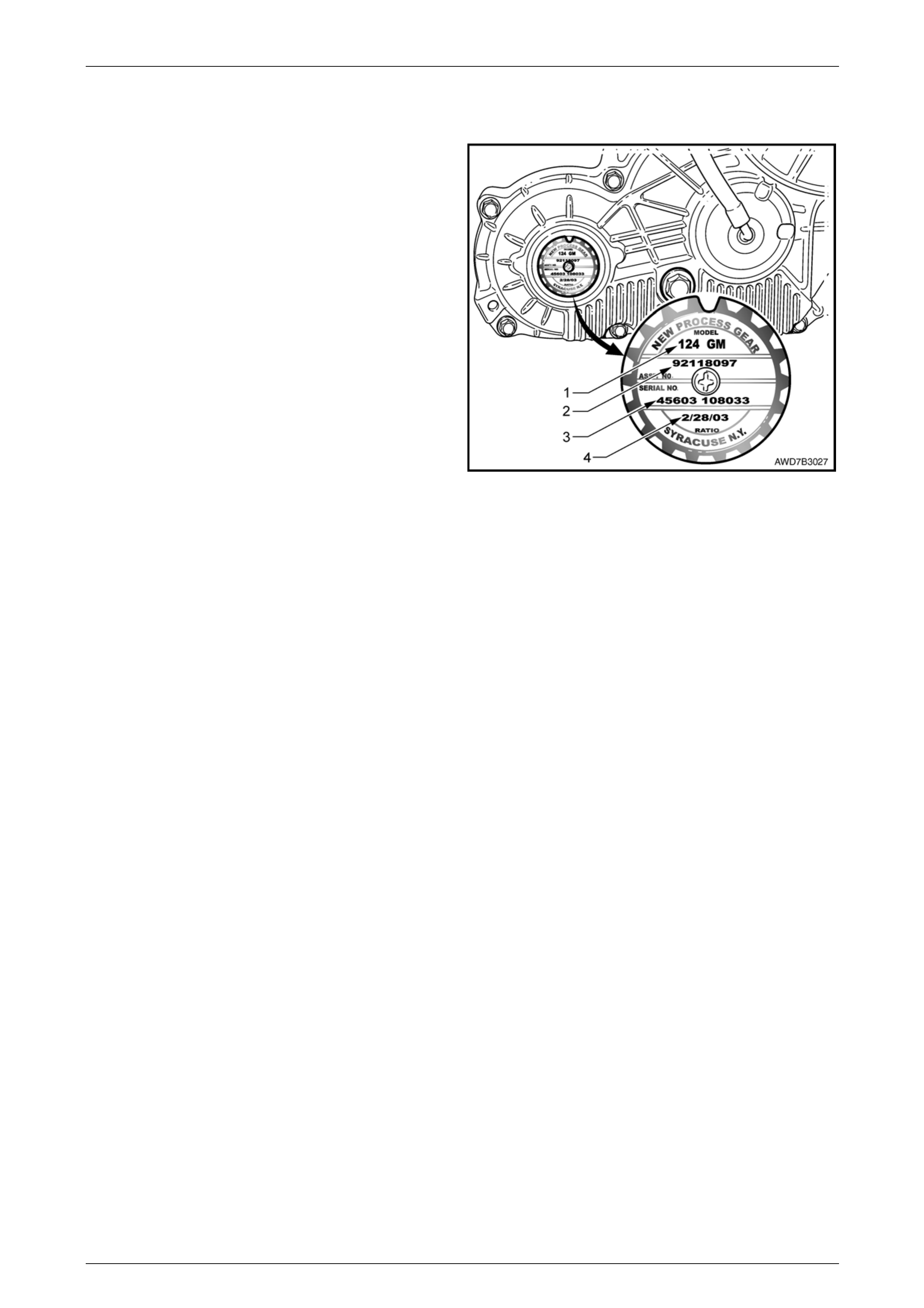
11.3 Transfer Case Assembly Serial Numbers
An identification tag is attached to the rear of the transfer
case housing, refer Figure 0A – 7. The information
contained on the tag provides the transfer case serial
number, build date and other information that may be
required for the correct procurement of service parts.
If the tag is removed or is dislodged during service
operations, the item is to be kept with the assembly.
Legend
1 Model Number ('124')
2 Assembly Part Number
3 Serial Number
4 Build Date
Figure 0A – 5
General Information Page 0A–16
Page 0A–16
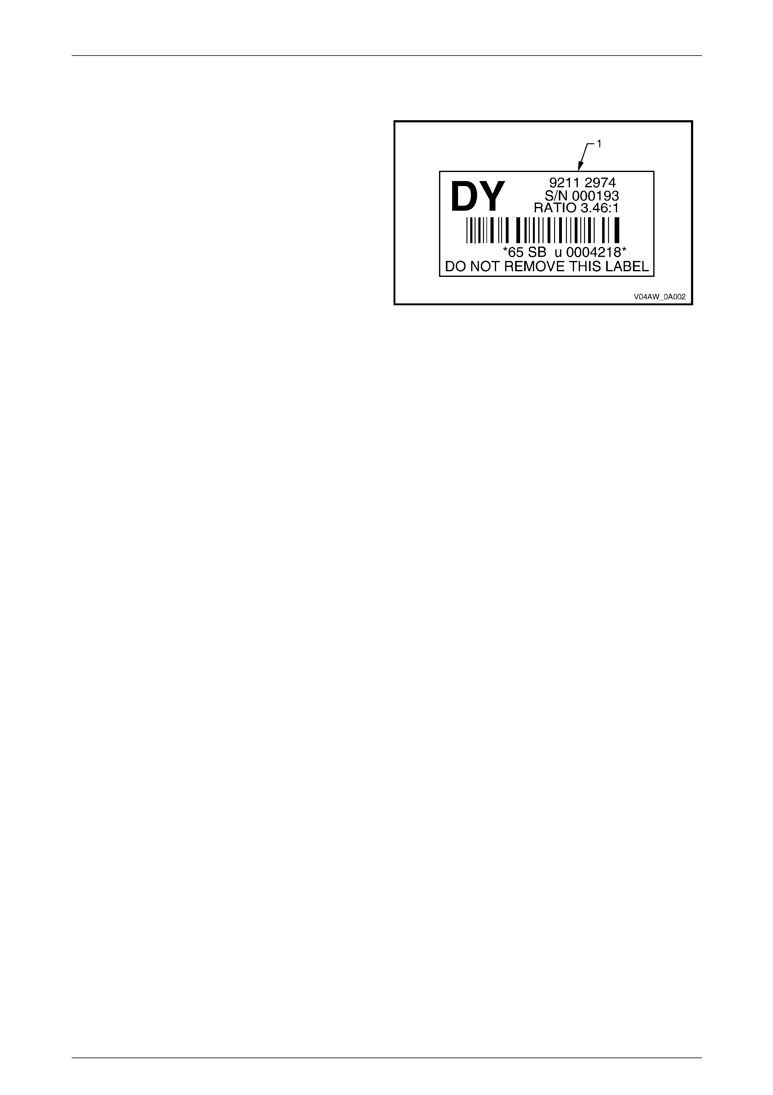
11.4 Front Final Drive
An identification label (1) is adhered to the front final drive
assembly on the left side towards the rear of the housing.
The label contains the Holden Part Number for the
assembly, the serial number of the assembly as well as
the final drive ratio.
The front final drive assembly is attached to the left-hand
side of the engine oil pan.
Figure 0A – 6
General Information Page 0A–17
Page 0A–17
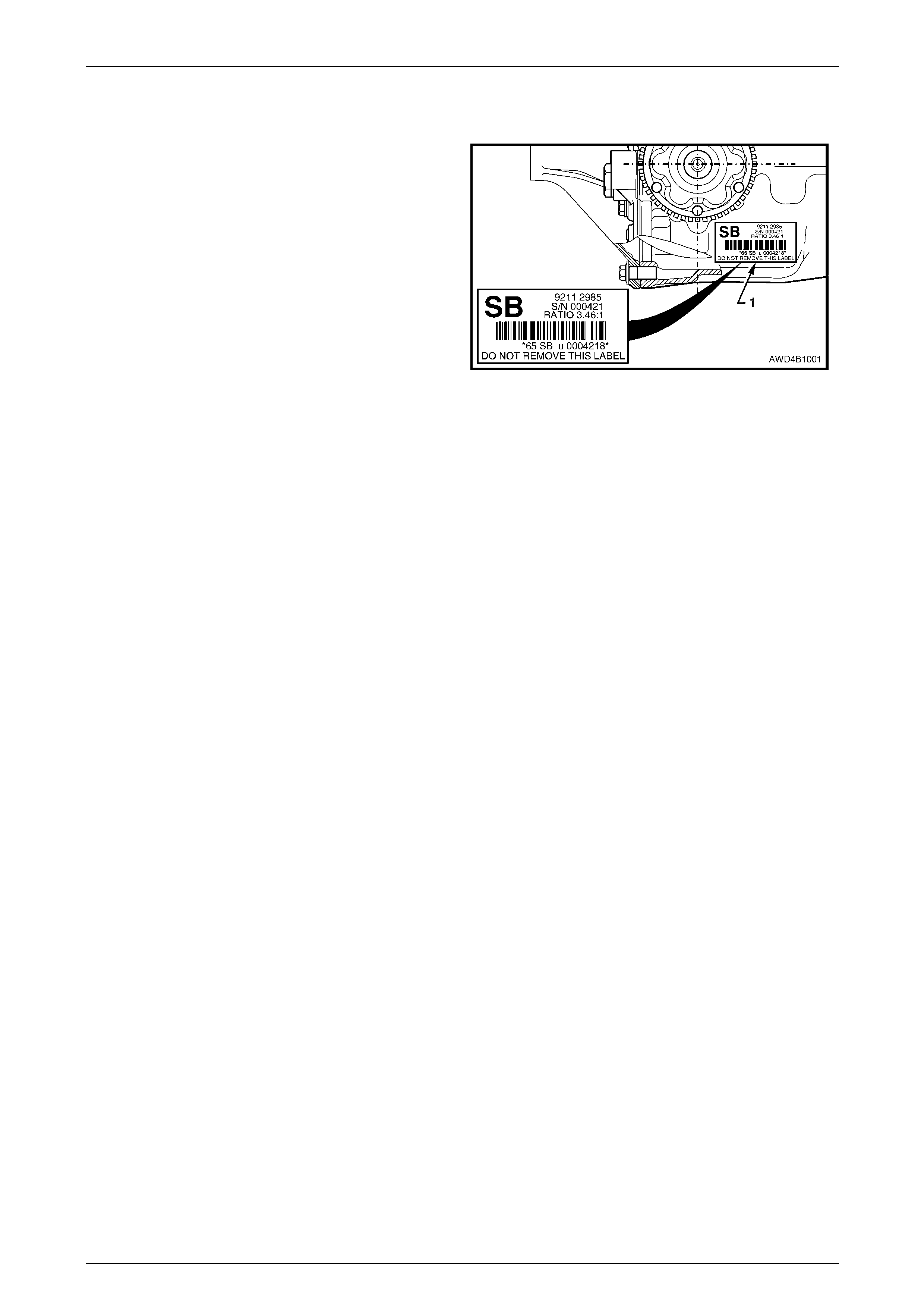
11.5 Rear Final Drive
An identification label is adhered to the rear final drive
assembly to the right-hand side of the carrier housi ng.
The label carries the Holden Part Number for the
assembly, the final drive ratio and the serial number of
the assembly.
Figure 0A – 7

General Information Page 0A–18
Page 0A–18
12 Special Tools
The following information lists the new Special Service Tools required for use on the MY 2004 AWD Wagon. All other
remaining Special Service Tools for use on MY 2004 AWD Wagon carry over from the MY 2003 VY and V2 Series. For
all other Special Service Tools not listed in this Section, refer to Section 0A, 16 Consolidated Tool List in the MY 2003 VY
and V2 Series Service Information.
These new tools are grouped accord ing to their application (transfer case, front suspensio n, front final dri ve and rear
suspension) and within each group, are listed in tool number alphabetical / numerical order. They are also classified into
the following categories:
Mandatory: When required to perform routine maintenance operations and adjustments, or are required to carry out fault
diagnosis procedures.
Desirable: T hese tools shou ld be considered for purchase since the ir use will greatly facilitate performing design ated
tasks and permit achievement of standard times.
Unique: These tools are those that must be employed when overhauling major assemblies or performing relatively large
tasks.
Available: Are those tools that are of general nature for which commercially available equivalents exists, or tools which
have had previous application.
Unless otherwise specified, all Special Service Tools are availabl e from:
SPX Australia Pty. Ltd.
Service Solutions
28 Clayton Road
Notting Hill, Victoria, 3168
Telephone: (03) 9544 6 222
Facsimile: (03) 9544 5222
Email: [email protected]
General Information Page 0A–19
Page 0A–19
Transfer Case
Tool Number Illustration Description Tool Classification
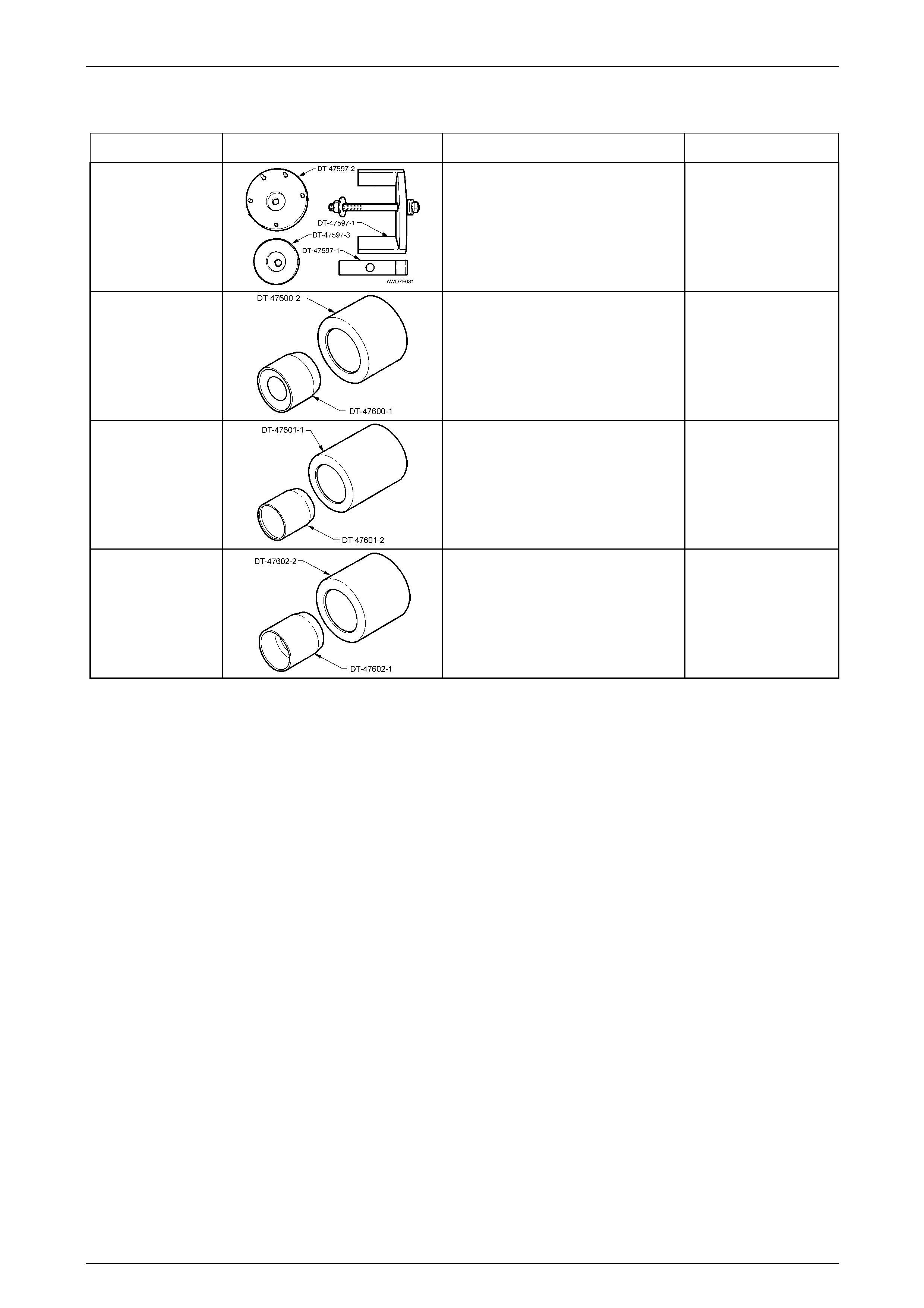
DT-47597
Rear Mount Remover / Installer
Used to remove and install the rear
support mount from / to the transfer
case.
New release
Available
DT-47600
Seal Protector and Installer
Used to protect and install the front
input shaft oil seal to the transfer
case.
New release
Available
DT-47601
Seal Protector and Installer
Used to protect and install the rear
output shaft oil seal to the transfer
case.
New release
Available
DT-47602
Seal Protector and Installer
Used to protect and install the front
output shaft oil seal to the transfer
case.
New release
Available
General Information Page 0A–20
Page 0A–20
Front Suspension
Tool Number Illustration Description Tool Classification
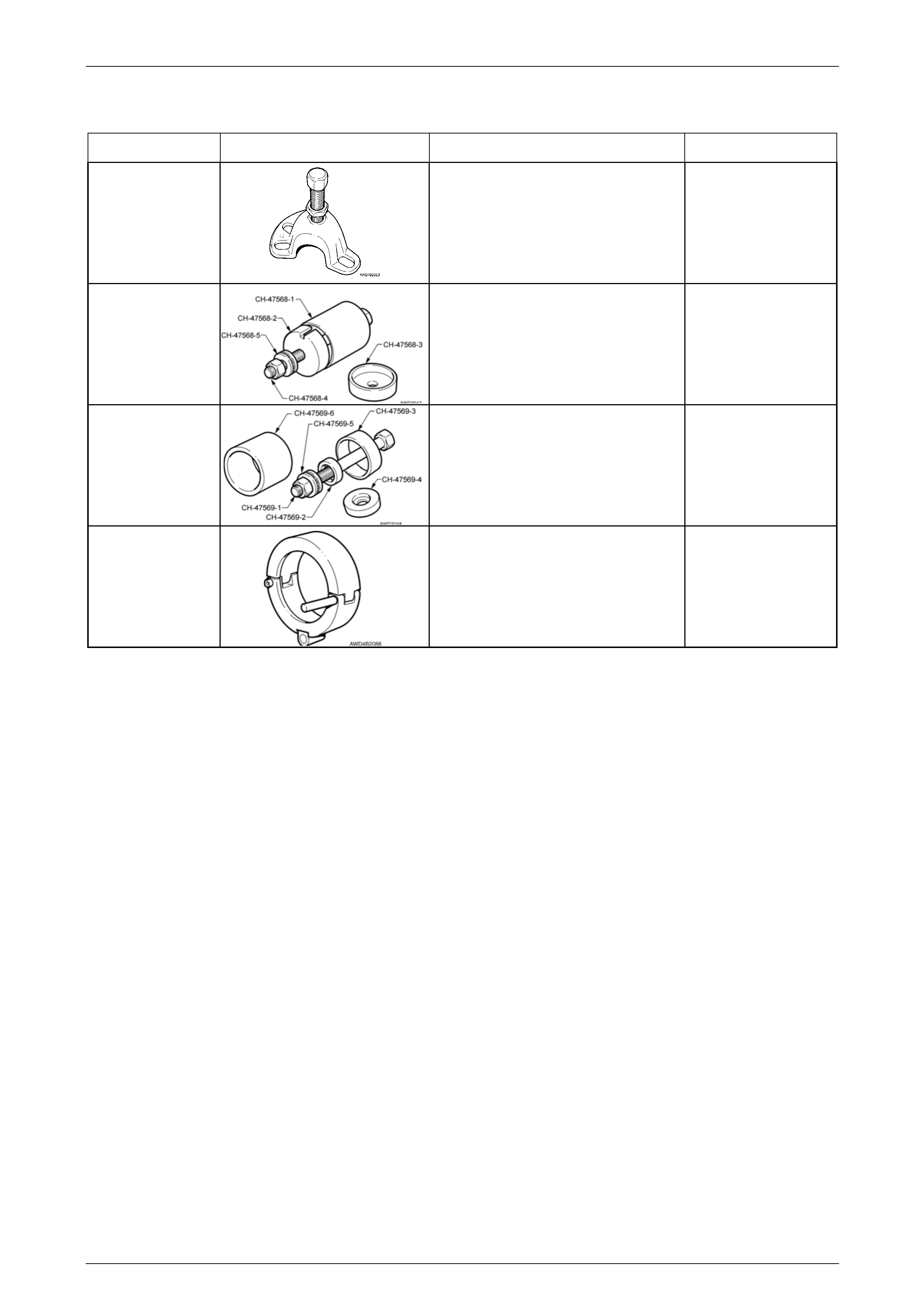
7208
Hub Puller
Used to press the front driveshaft from
the front hub. Also used to check LSD
breakaway torque on final dri ves so
equipped.
Previously released
Mandatory
CH-47568 Remover / Installer Control Arm,
Front Isolator Bush
Used to remove and install the front
control arm, front hydraulic bushing
from / to the front suspension
crossmember cradle.
New release.
Available
CH-47569 Remover / Installer Control Arm,
Rear Bush
Used to remove and install the rear
bushing, from / to the front control
arm. New release.
Available
DT-47570 Remover / Installer, Front
Driveshafts
Used in conjunction with slide hammer
J 6125-1B (and adaptor), or J 23907
slide hammer to remove and reinstall
the front driveshafts.
New release.
Mandatory
General Information Page 0A–21
Page 0A–21
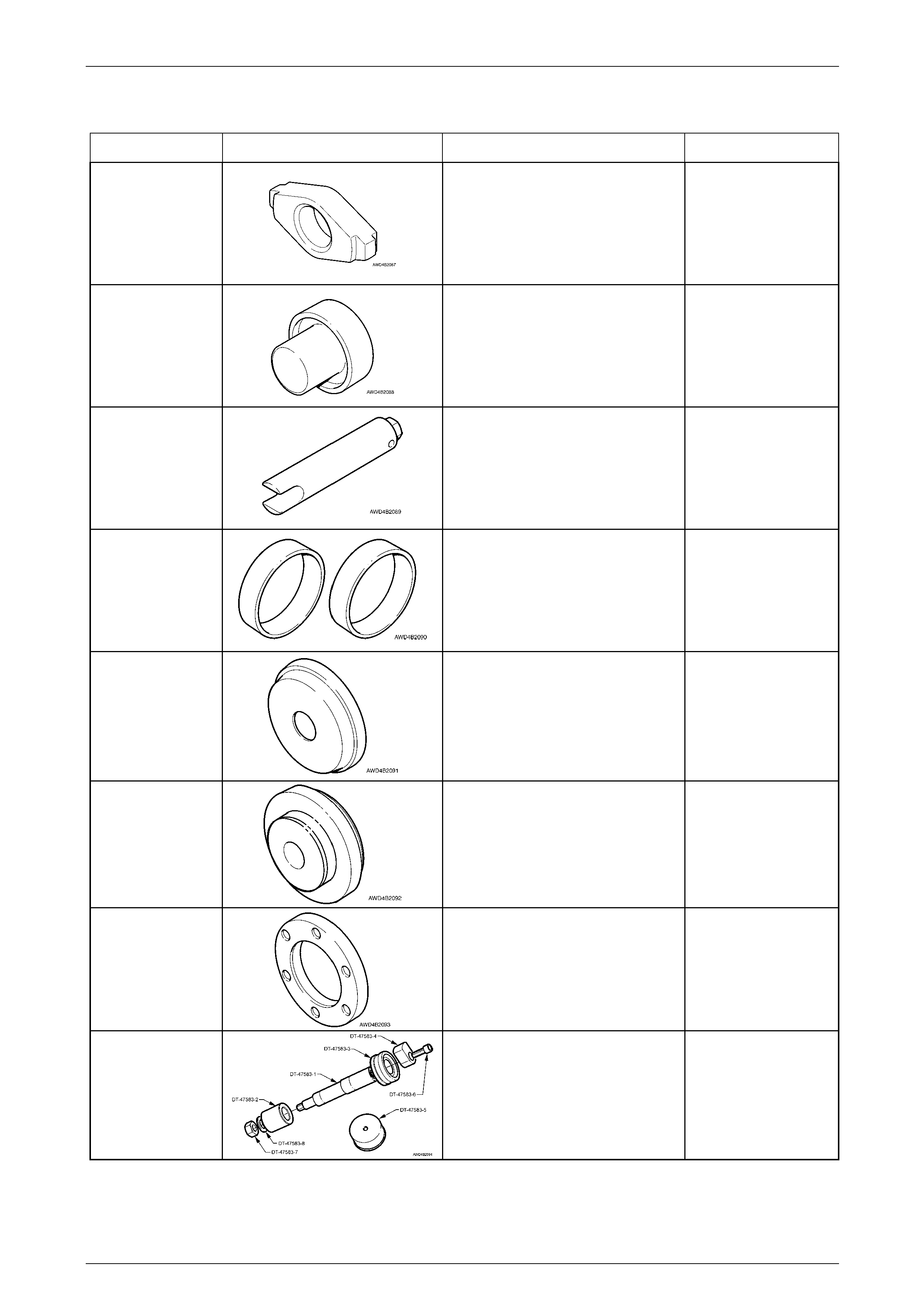
Front Final Drive
Tool Number Illustration Description Tool Classification
DT-47571
Cup Removal Adaptor
Used in conjunction with E9293 to
remove both pinion bearing cups from
the carrier housing.
New release
Available
DT-47572
Side Bearing Installer
Used with a hydraulic press to install
the differential carrier bearing cones.
New release
Available
DT-46573
Ring Gear Rotation Tool
Used to rotate differential housing to
measure bearing preload.
New Release
Mandatory
DT-47577
Dummy Bearing Cups
Used when determining the
differential bearing preload and
position.
New release.
Available
DT-47578
Bearing Cup Installer
Used in conjunction with bearing cup
alignment tool, DT-47579, to install
the ring gear carrier bearing cups to
the carrier and cover housings .
New release
Available
DT-47579
Bearing Cup Alignment Tool
Used in conjunction with bearing cup
installer, to ensure that bearing cups
are installed correctly.
New release.
Available
DT-47580
Spacer Ring
Fitted into the pinion flange to act as a
spacer for holding tool J8614-O1.
New Release
Available
DT-47583
Dummy Pinion
Used to determine the pinion bearing
preload and position.
New release
Available
General Information Page 0A–22
Page 0A–22
Rear Suspension
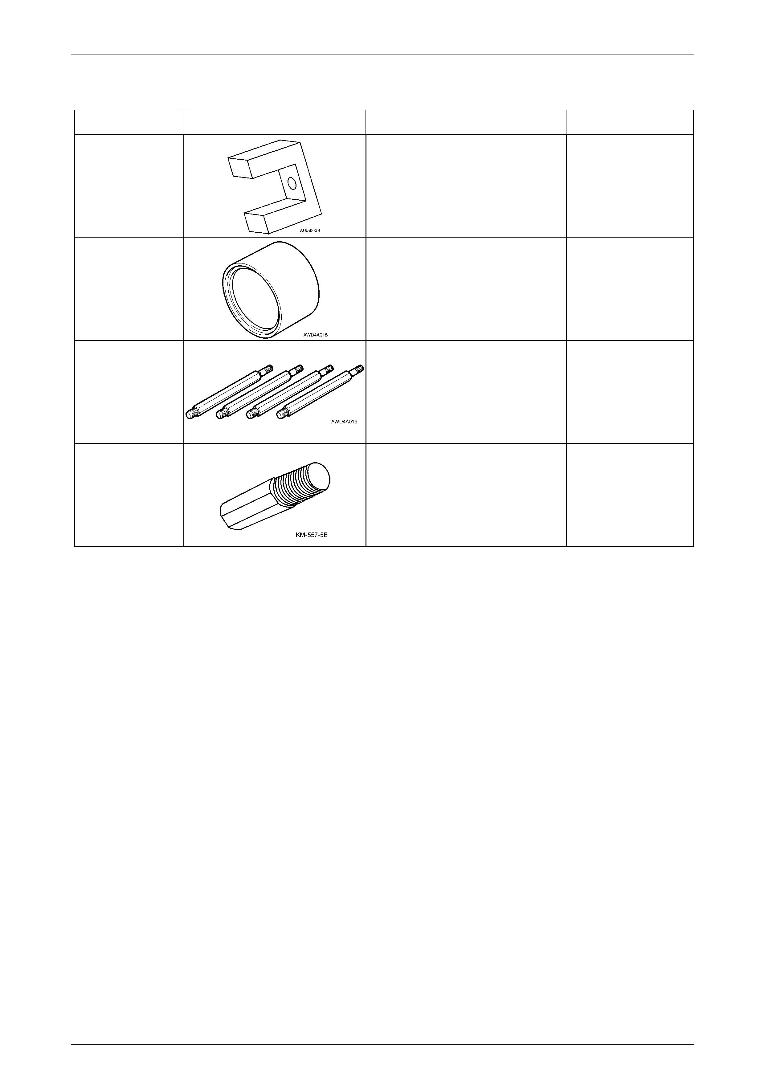
Tool Number Illustration Description Tool Classification
AU 592-3B
Support Block
Used with the plate, bolt and nut of
AU 592 to install the hydraulic bush
into the front of the rear crossmember.
New release
Available
CH-47575
Rear Wheel Bearing Receiver
Used to support the trailing arm
bearing hub when the bearing is being
removed.
New release
Mandatory
DT-47574 Stand Offs
Used with selected components of
Tool No. KM 620-1A when installin g a
new rear wheel bearing.
New release
Mandatory
KM 557-5B
Adaptor
Used with AU 592-2 and AMKM-557 to
remove the rear crossmember front
hydraulic mount when the crossmember
has been removed from the vehicle.
New release
Available