
Body Page 1A1–1
Page 1A1–1
Section 1A1
Body
ATTENTION
Before performing any service operation or other procedure described in this Section, refer to Section 00
Warnings, Cautions and Notes for correct workshop practices with regard to safety and/or property damage.
1 General Information............................................................................................................................... 2
2 Service Operations................................................................................................................................ 3
2.1 Plastic Components...............................................................................................................................................3
2.2 Front Wheelhouse Liner........................................................................................................................................5
Remove ...................................................................................................................................................................5
Reinstall..................................................................................................................................................................6
2.3 Rear Wheelhouse Liner .........................................................................................................................................7
Remove ...................................................................................................................................................................7
Reinstall..................................................................................................................................................................8
3 Torque Wrench Specifications............................................................................................................. 9

Body Page 1A1–2
Page 1A1–2
1 General Information
With the following exceptions, MY 2004 VY AWD Wagon Body information carries over from the MY 2004 VY Series
vehicles.
• Plastic components
• Front wheelhouse liner
• Rear wheelhouse liner
For Body information not contained within this Section, refer to Section 1A1 Body in the MY 2004 VY and V2 Series
Service Information.
Body Page 1A1–3
Page 1A1–3
2 Service Operations
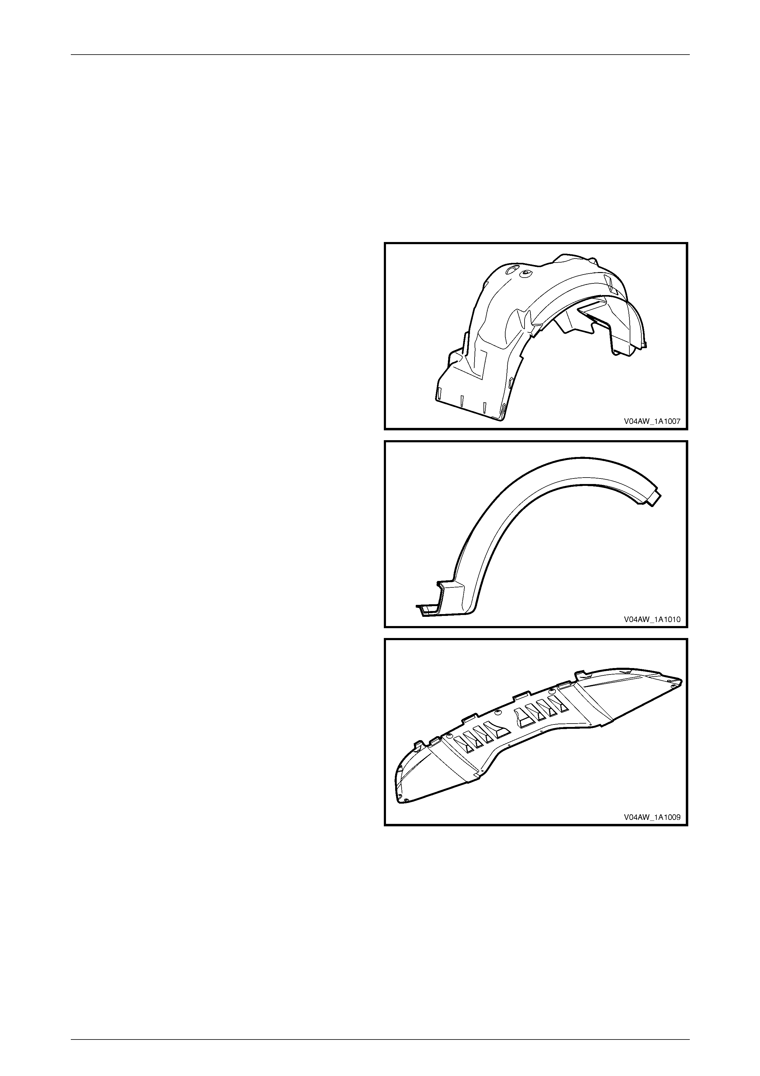
2.1 Plastic Components
NOTE
Most components are also identified with the
material code in an inconspicuous place.
Front Wheelhouse Liner
Rear Wheelhouse Liner
Material: PP
Front Wheelhouse Opening Flare
Rear Wheelhouse Opening Flare
Material: PP
Front Bumper Fascia Undertray
Material: PP
Body Page 1A1–4
Page 1A1–4
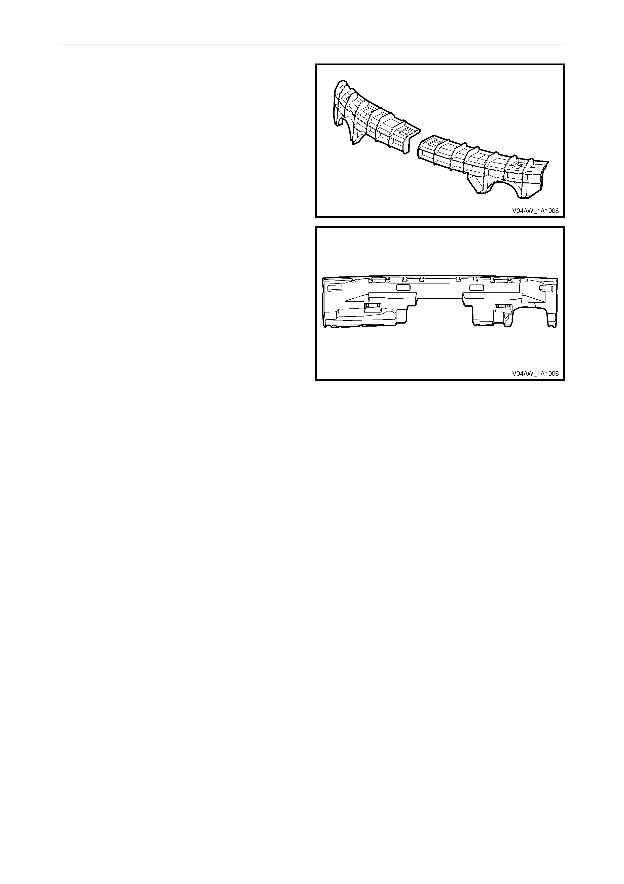
Front Bumper Fascia Support
Material: ABS
Rear Bumper Fascia Filler
Material: PP Foam
Body Page 1A1–5
Page 1A1–5
2.2 Front Wheelhouse Liner
LT Section 12–425
Remove
1 Remove the front road wheel, refer to Section 10 Wheels & Tyres.
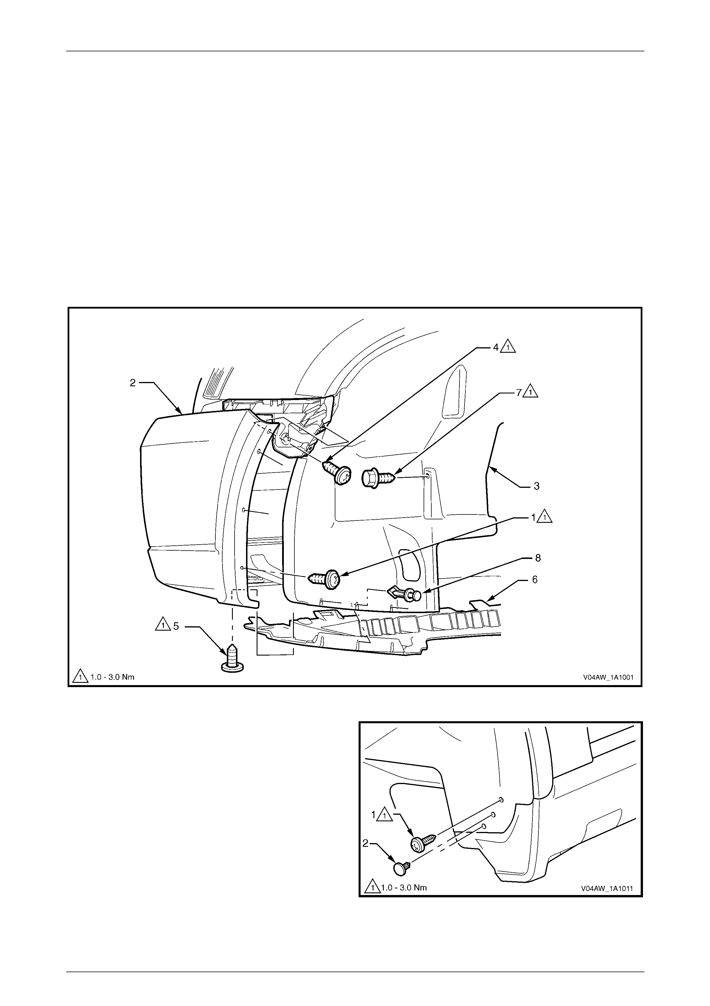
2 Remove the screw (1), two places, attaching the front bumper fascia assembly (2) to the front wheelhouse liner
(3), refer to Figure 1A1 – 1.
3 If required, also remove the screws (4), two places, attaching the fascia assembly to the vehicle, and the screw (5)
attaching the fascia to the fascia undertray (6), to aid in removal of the liner.
4 Remove the screw (7) attaching the liner to the vehicle.
5 Remove the retainers (8), three places, attaching the liner to the fascia undertray.
Figure 1A1 – 1
6 Remove the screws (1), two places, attaching the liner
to the vehicle.
7 Remove the retainer (2), attaching the liner to the
vehicle.
Figure 1A1 – 2
Body Page 1A1–6
Page 1A1–6
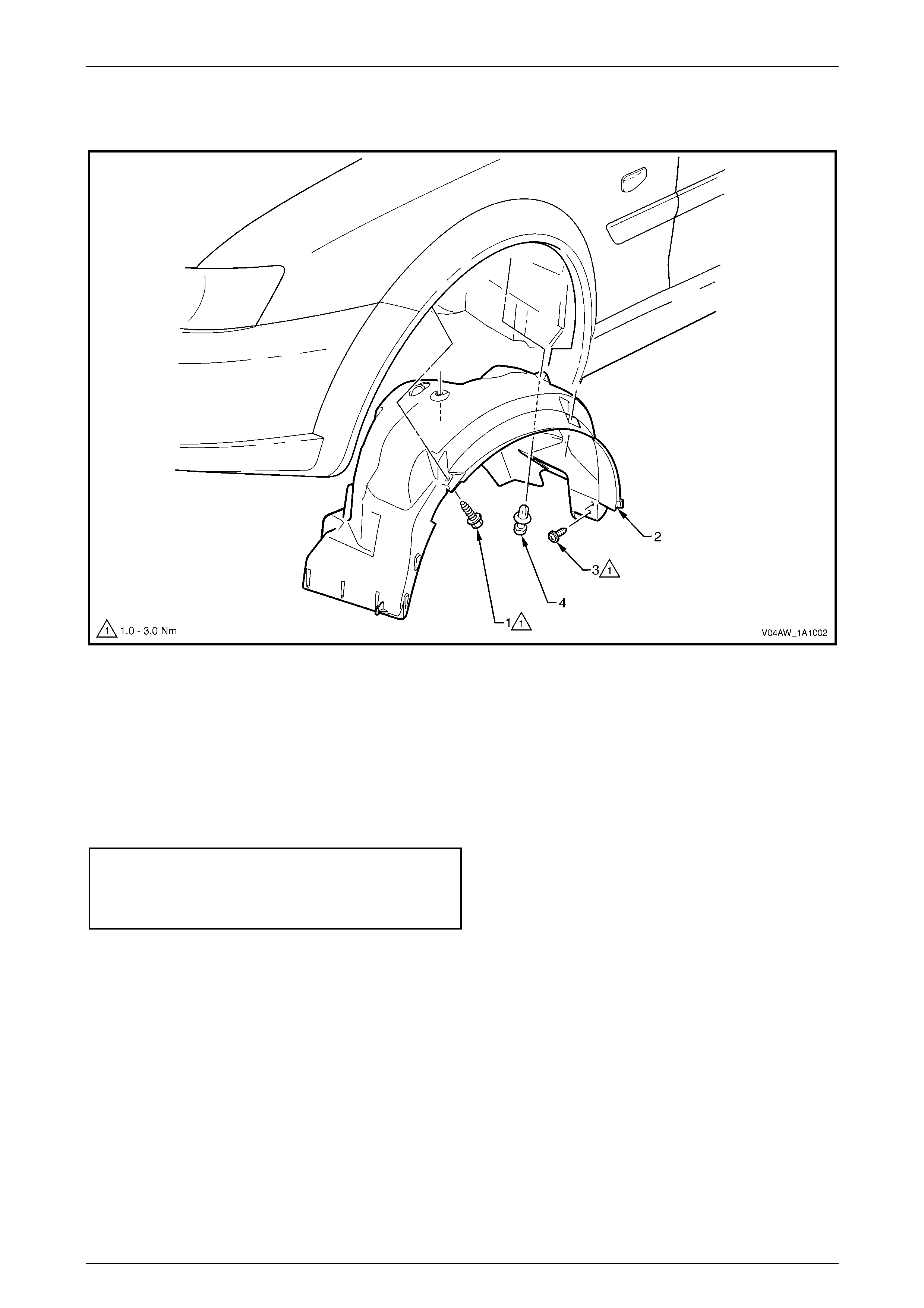
8 Remove the screws (1), two places, attaching the liner (2) to the flare and fender, refer to Figure 1A1 – 3.
9 Remove the retainers (3), two places, attaching the liner to the vehicle.
Figure 1A1 – 3
10 Manipulate the liner from behind the wheelhouse flare and bumper fascia and remove.
Reinstall
Reinstallation of the front wheelhouse liner is the reverse of the removal procedure, noting the following.
1 Ensure the wheelhouse liner is correctly positioned.
2 Install the attaching screws and tighten to the correct torque specification.
Front wheelhouse liner attaching s crew
torque specification.............................................. 1.0 – 3.0 Nm
Front bumper fasci a assembly attac hi ng screw
torque specification.............................................. 1.0 – 3.0 Nm
Body Page 1A1–7
Page 1A1–7
2.3 Rear Wheelhouse Liner
Remove
1 Remove the rear road wheel, refer to Section 10 Wheels & Tyres.
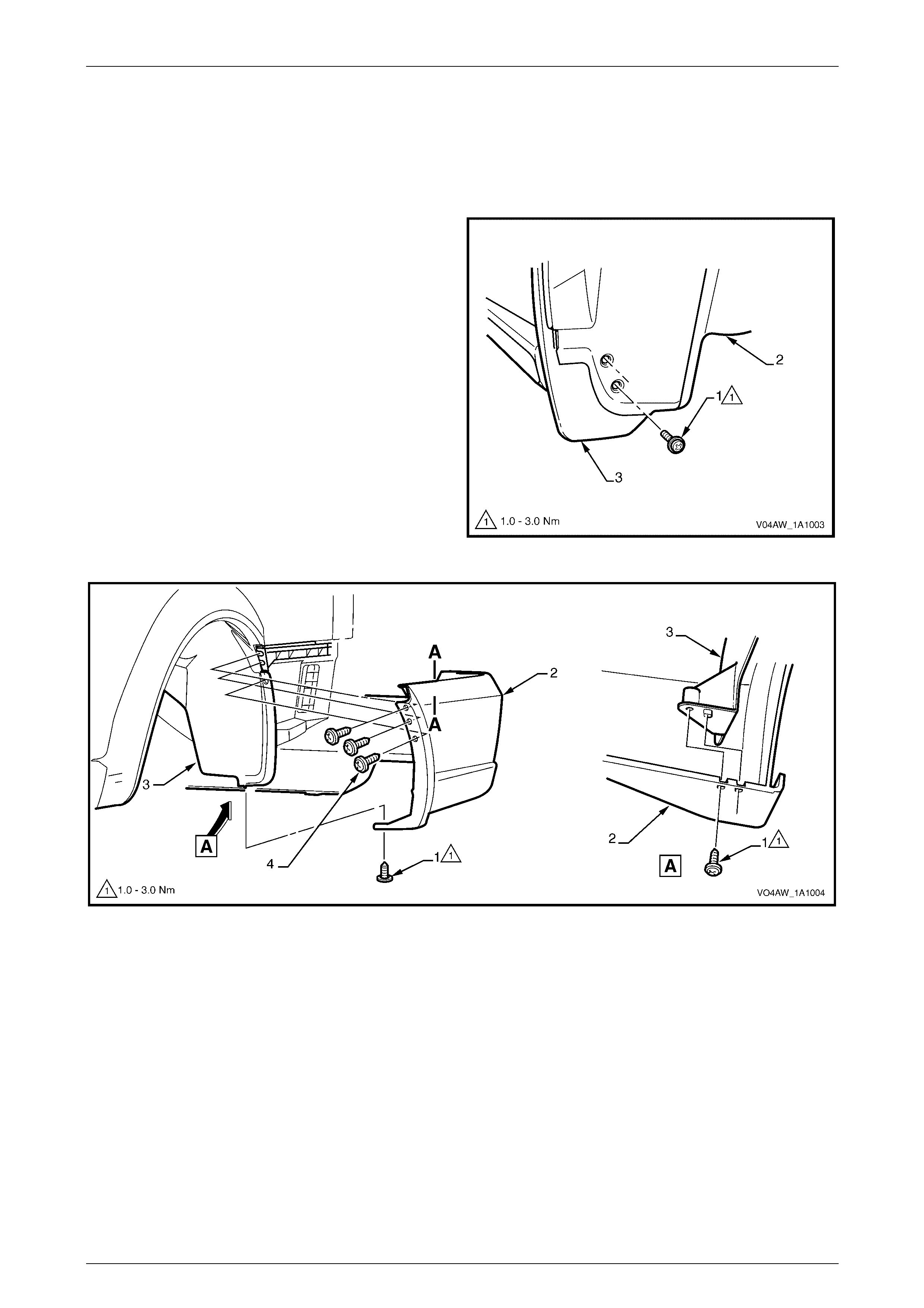
2 Remove the screw (1) two places, attaching the rear
wheelhouse liner (2) and rocker panel moulding
assembly (3) to the vehicle.
3 Remove the screw (1), attaching the rear bumper
fascia assembly (2) to the wheelhouse liner (3), refer
to Figure 1A1 – 5.
4 Remove the screws (4), three places, attaching the
rear bumper fascia assembly to the liner and rear
bumper fascia guide.
Figure 1A1 – 4
Figure 1A1 – 5
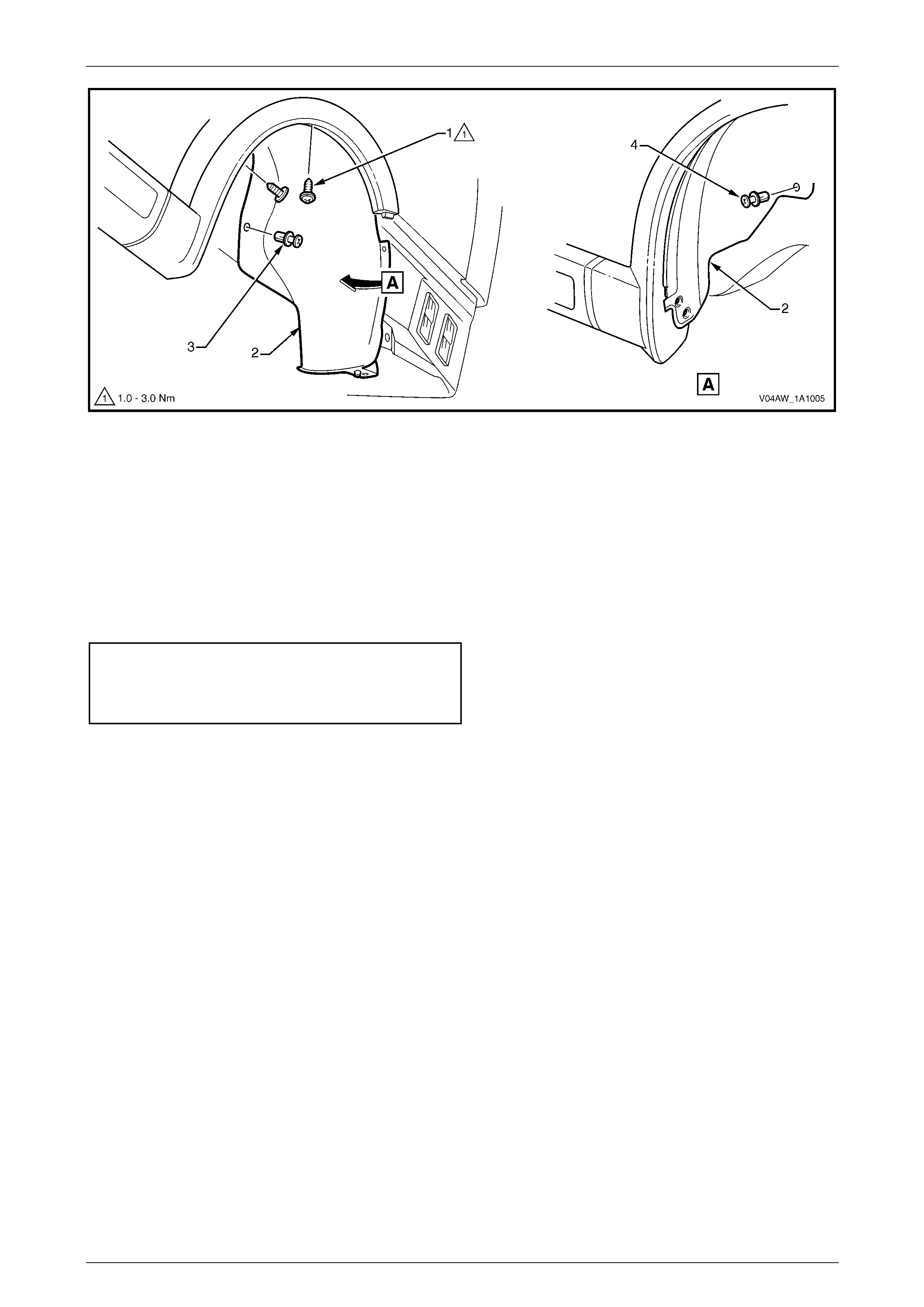
5 Remove the screws (1) two places, attaching the liner (2) to the flare and rear quarter panel, refer to
Figure 1A1 – 6.
6 Remove the retainers (3 & 4) attaching the liner (2) to the wheelhouse panel.
Body Page 1A1–8
Page 1A1–8
Figure 1A1 – 6
7 Manipulate the liner from behind the wheelhouse flare and bumper fascia and remove.
Reinstall
Reinstallation of the rear wheelhouse liner is the reverse of the removal procedure, noting the following.
1 Ensure the wheelhouse liner is correctly positioned, refer to Figure 1A1 – 4.
2 Engage the pin on the liner with the hole in the rear bumper fascia, refer to Figure 1A1 – 5.
3 Install the screws attaching the liner and tighten to the correct torque specification.
Rear wheelhouse liner att aching sc rew
torque specification.............................................. 1.0 – 3.0 Nm
Rear bumper f ascia as sembl y at taching s crew
torque specification.............................................. 1.0 – 3.0 Nm

Body Page 1A1–9
Page 1A1–9
3 Torque Wrench Specifications
Front Wheelhouse Liner Attaching Screw.....................................1.0 – 3.0 Nm
Rear Wheelhouse Liner Attaching Screw......................................1.0 – 3.0 Nm
Front Bumper Fascia Assembly Attaching Screw..........................1.0 – 3.0 Nm
Rear Bumper Fascia Assembly Attaching Screw.......................... 1.0 – 3.0 Nm