
Body Dimensi ons Page 1A2–1
Page 1A2–1
Section 1A2
Body Dimensions
ATTENTION
Before performing any service operation or other procedure described in this Section, refer to Section 00
Warnings, Cautions and Notes for correct workshop practices with regard to safety and/or property damage.
1 General Information............................................................................................................................... 2
1.1 Front Suspension Frame Assembly.....................................................................................................................2
1.2 Transmission Rear Crossmember and Transfer Case Rear Mounting Bracket................................................3
2 Service Procedures ............................................................................................................................... 4
2.1 Rear Suspension Frame Assembly ......................................................................................................................4
Rear Suspension Frame Assembly Alignment....................................................................................................4
3 Torque Wrench Specifications............................................................................................................. 8
4 Special Tools.......................................................................................................................................... 9

Body Dimensi ons Page 1A2–2
Page 1A2–2
1 General Information
With the following exceptions, MY 2004 VY AWD Wagon Body Dimension Information carries over from MY 2003 VY
Wagon vehicles.
• Front suspensio n frame as se mbly .
• Transmission rear crossmember and transfer case rear mounting bracket.
• Rear suspension frame assembly.
While there are minor differences in the body structure between the AWD Wagon and the conventional Wagon, the
dimensional measuring points are the same.
For all body dimension information, refer to Section 1A2 Body Dimensions in the MY 2003 VY Series and V2 Series
Service Information.
1.1 Front Suspension Frame Assembly
A new front suspension frame assembly is fitted to suit the AWD application.
While there are minor differences in the construction of the front suspension frame assembly, the installation and
alignment procedures carry over from MY 2003 VY Series vehicles, refer to Section 1A2 Body Dimensions in the
MY 2003 VY and V2 Series Service Information.

Body Dimensi ons Page 1A2–3
Page 1A2–3
1.2 Transmission Rear Crossmember and
Transfer Case Rear Mounting Bracket
A new transmission rear crossmember and transfer case rear mounting bracket is fitted to MY 2004 VY AWD Wagon
vehicles to accommodate the transfer case.
While no specific alignment procedures are required, it is important to either mark the position of the bolts before
removal, or ensure that the holes are centralised before re-assembly. For further information, refer to Section 7F,
3.1 Transfer Case.

Body Dimensi ons Page 1A2–4
Page 1A2–4
2 Service Procedures
ATTENTION
All rear suspension fasteners are important attaching parts as they affect the performance of vital
components and/or could result in major repair expense. Where specified in this section, fasteners must be
replaced with parts of the same part number or a Holden approved equivalent. Do not use fasteners of an
inferior quality or substitute design.
Torque values must be used as specified during reassembly to ensure proper retention of all suspension
components.
Through out this section, fastener torque wrench specifications may be accompanied with the following
Identification marks:
!
!!
! Fasteners must be replaced after loosening.
"
""
" Vehicle must be at curb height before final tightening.
#
##
# Fasteners either have micro encapsulated sealant applied or incorporate a mechanical thread lock and
should only be re-used once. If in doubt, replacement is recommended.
If one of these identification marks is present alongside a fastener torque wrench specification, the
recommendation regarding that fastener must be adhered to.
2.1 Rear Suspension Frame Assembly
Rear Suspension Frame Assembly Alignment
LT Section No. 07-150A
NOTE
The rear suspension frame assembly centering
tool needs to be held in position during the
alignment procedure. Therefore, assistance will
be required to complete this operation.
Body Dimensi ons Page 1A2–5
Page 1A2–5
1 Using chassis stands (1) support the vehicle at hoist
pad locations.
2 Remove the rear wheels, refer to Section 10 Wheels
and Tyres.
3 Remove the intermediate muffler and pipe assembly
together with the rear muffler and pipe assembly, refer
to Section 8B Exhaust System.
4 From underneath the vehicle, support the final drive
assembly with a trolley jack. Raise the jack slightly to
take some of the weight off the final drive mount.
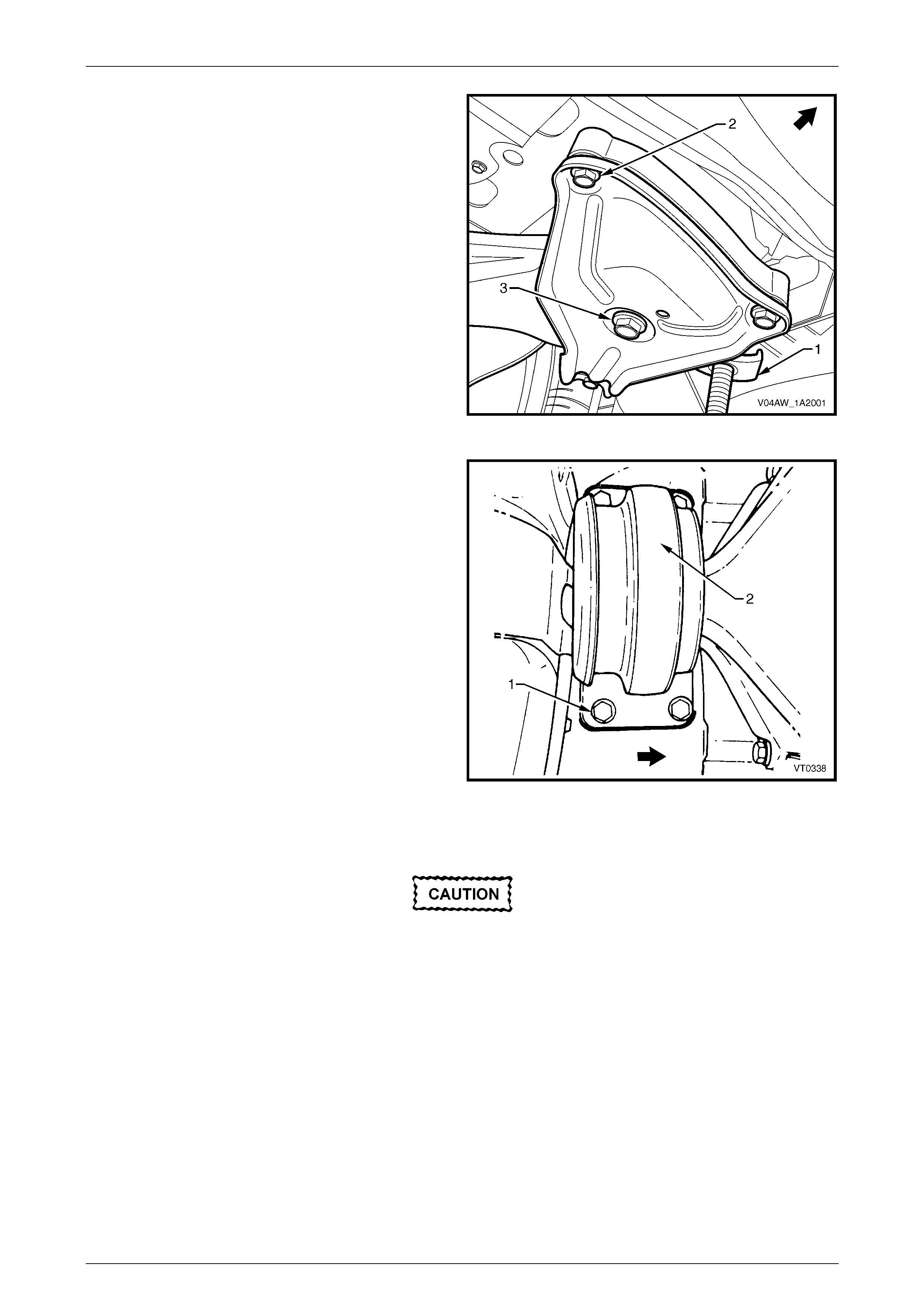
5 Loosen the M10 bolt (2), three places, attaching the
rear suspension support insulator bracket to the
vehicle, left-hand and right-hand side.
6 Loosen the rear suspension frame assembly M14
attaching bolt (3) left-hand and right-hand side.
Figure 1A2 – 1
7 Loosen the bolt (1), four places, attaching the final
drive rear mount (2).
Figure 1A2 – 2
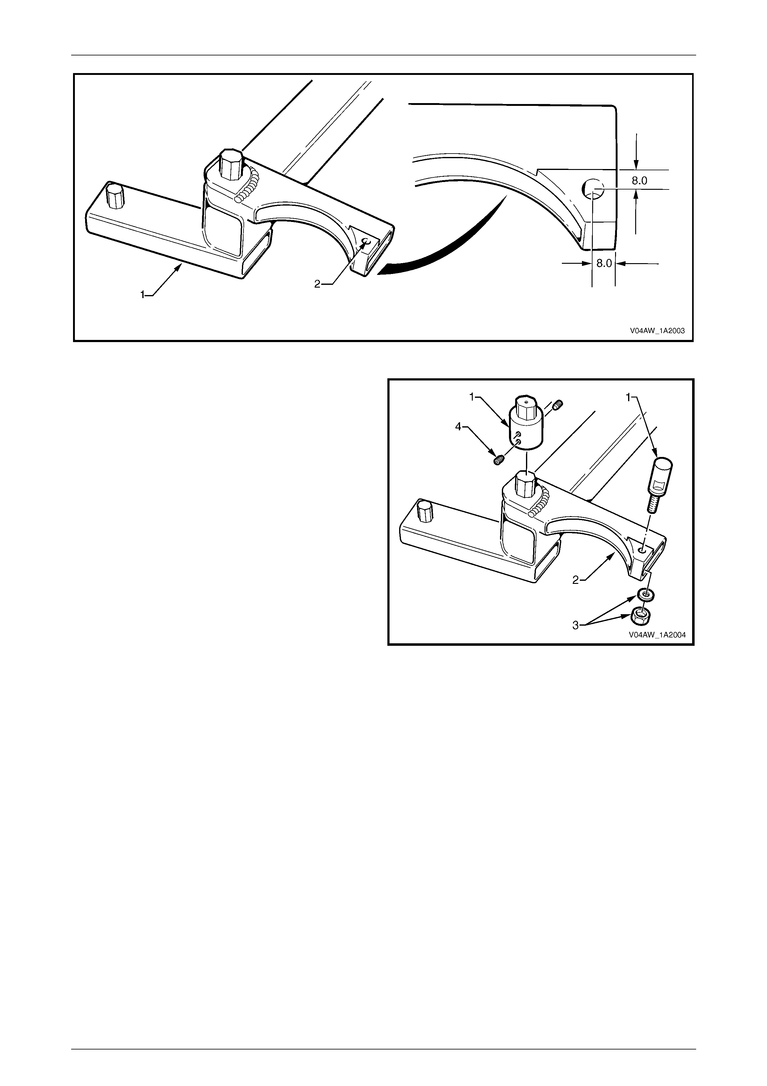
8 If required, modify the rear crossmember centering tool No CH-46839 (AU458) (1), refer to Figure 1A2 – 3:
Do not attempt to drill the hole in the rear
crossmember centering tool without a drill
press, as the tool will be rendered inaccurate
if the hole is not drilled square to the surface
of the tool.
a) Mount the rear crossmember centering tool in a drill press.
b) Drill a 6 mm hole (2) through the landing on the top surface of the tool, 8.0 mm from the edges as shown.
c) Repeat steps a) and b) for the other end of the tool.
Body Dimensi ons Page 1A2–6
Page 1A2–6
Figure 1A2 – 3
9 Fit the rear crossmember centering tool adaptor pins
No CH47621 (1) to the rear crossmember centering
tool (2). Fit and tighten the nut and washer (3). Tighten
the grub screws (4).
NOTE
Ensure that the adaptor pins with the hexagonal
heads are fitted on to the side of the tool with the
hexagonal pins.
Figure 1A2 – 4
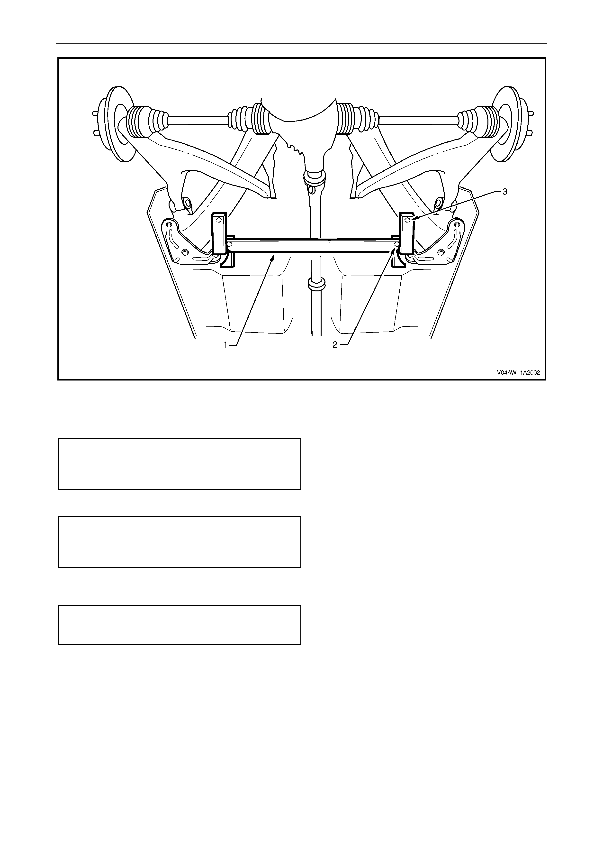
10 Fit rear crossmember centering tool (1) to the vehicle, refer to Figure 1A2 – 5.
NOTE
The rear crossmember centering tool locates into
19 mm diameter body datum holes (2) positioned
forward of the rear suspension frame assembly.
11 With the help of an assistant, manoeuvre the rear suspension assembly until the location pins of the rear
crossmember centering tool engage the alignment holes (3) on the rear frame assembly.
Body Dimensi ons Page 1A2–7
Page 1A2–7
Figure 1A2 – 5
12 Tighten the rear frame assembly M14 attaching bolt (3) right-hand and left-hand side to the specified torque, refer
to Figure 1A2 – 1.
! Rear suspension frame
assembly attaching bolt
torque specification ......................Stage 1 125.0 Nm
.............. Stage 2 Turn 30° – 40°
13 Tighten the bolt (1), four places, attaching the final drive rear mount (2), refer to Figure 1A2 – 2.
! Final drive rear mount
attaching bolt torque
specification .............Stage 1 30.0 – 40.0 Nm
.............. Stage 2 Turn 55° – 65°
14 Tighten to the specified torque, the M10 bolt (2), three places, attaching the rear suspension support insulator
bracket to the vehicle, right-hand and left-hand side, refer to Figure 1A2 – 1.
Rear suspens ion sup port ins ul ator
bracket attaching bolt torque
specification............................................60.0 – 85.0 Nm
15 Remove the rear crossmember centering tool.
16 Gently lower the trolley jack and remove from under the vehicle.
17 Refit the rear wheels, refer to Section 10 Wheels and Tyres.
18 Remove the vehicle from the chassis stands.

Body Dimensi ons Page 1A2–8
Page 1A2–8
3 Torque Wrench Specifications
ATTENTION
All rear suspension fasteners are important attaching parts as they affect the performance of vital
components and/or could result in major repair expense. Where specified in this section, fasteners MUST be
replaced with parts of the same part number or a Holden approved equivalent. Do not use fasteners of an
inferior quality or substitute design.
Torque values must be used as specified during reassembly to ensure proper retention of all suspension
components.
Through out this section, fastener torque wrench specifications may be accompanied with the following
Identification marks:
!
!!
! Fasteners must be replaced after loosening.
"
""
" Vehicle must be at curb height before final tightening.
#
##
# Fasteners either have micro encapsulated sealant applied or incorporate a mechanical thread lock and
should only be re-used once. If in doubt, replacement is recommended.
If one of these identification marks is present alongside a fastener torque wrench specification, the
recommendation regarding that fastener must be adhered to.
! Rear Suspension Frame Assembly Attaching Bolt............. Stage 1 125.0 Nm
.......................................................................................Stage 2 Turn 30° – 40°
! Final Drive Rear Mount Attaching Bolt...................... Stage 1 30.0 – 40.0 Nm
.......................................................................................Stage 2 Turn 55° – 65°
Rear Suspension Support Insulator Bracket Attaching Bolt.......60.0 – 85.0 Nm
Body Dimensi ons Page 1A2–9
Page 1A2–9
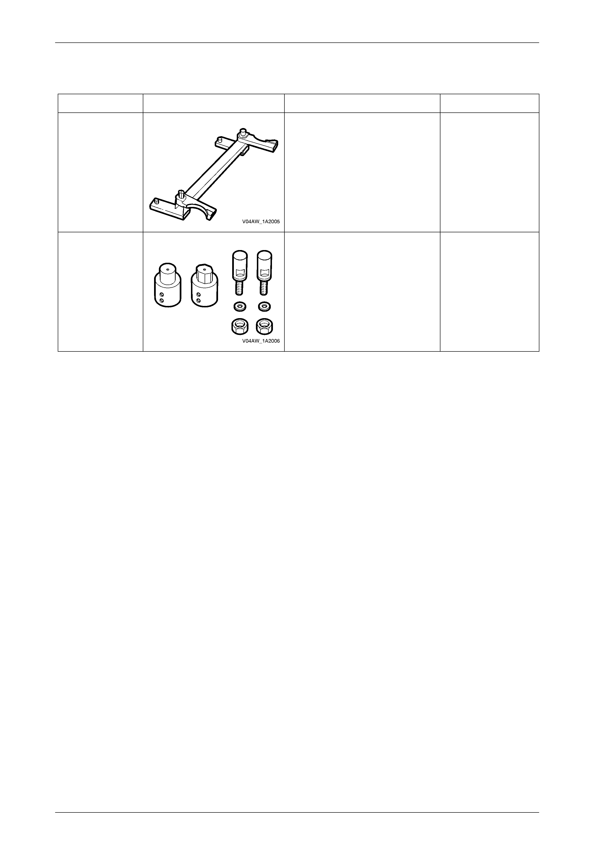
4 Special Tools
Tool Number Illustration Description Tool Classification
CH46839
(AU458)
Rear Crossmember Centering Tool.
Previously released. Mandatory.
CH47621
Rear Crossmember Centering Tool
Adaptor Pins. Mandatory.