
Instrument P anel and Console Page 1A3–1
Page 1A3–1
Section 1A3
Instrument Panel and Console
ATTENTION
Before performing any service operation or other procedure described in this Section, refer to Section 00
Warnings, Cautions and Notes for correct workshop practices with regard to safety and/or property damage.
1 General Information............................................................................................................................... 2
1.1 Instrument Panel Components - High Level........................................................................................................3
2 Service Operations................................................................................................................................5
2.1 Inclinometer Assembly..........................................................................................................................................5
Remove ...................................................................................................................................................................5
Disassemble ...........................................................................................................................................................6
Reassemble ............................................................................................................................................................7
Reinstall ..................................................................................................................................................................7
3 Torque Wrench Specifications............................................................................................................. 8
Techline
Techline
Techline

Instrument P anel and Console Page 1A3–2
Page 1A3–2
1 General Information
With the following exceptions, MY 2004 VY AWD Wagon Instrument Panel and Console information carries over from
MY 2004 VY and V2 Series vehicles.
• Inclinometer assembly for High Level vehicles.
For Instrument Panel and Console information not contained within this Section, refer to Section 1A3 Instrument Panel
and Console in the MY 2004 VY and V2 Series Service Information.

Instrument P anel and Console Page 1A3–3
Page 1A3–3
1.1 Instrument Panel Components - High
Level
Figure 1A3 – 1

Instrument P anel and Console Page 1A3–4
Page 1A3–4
Legend
1 Windshield Defroster Grille, Right-hand
2 Windshield Defroster Grille, Left-hand
3 Instrument P anel Inflat abl e Rest raint B racket
4 Steering Column Bracket Inner Brace
5 Steering Colum n Brack et Outer Brace
6 Instrument P anel Outer Cover, Ri ght-hand
7 Instrument Cl ust e r Trim Assembly
8 Instrument P anel Inflat abl e Rest raint Openi ng Trim Cover
9 Instrument P anel Lower Brack et
10 Instrument P anel Compartment Hinge (2 places)
11 Instrument P anel Compartment Bracket
12 Instrument P anel Outer Cover, Left-hand
13 Instrument P anel Lower Trim Plate Assembly, LH
14 Radio Bracket Assem bl y
15 Instrument P anel Compartment Lock Striker
16 Radio Housing
17 Instrument P anel Lower Trim Plate Assembly, Right-hand
18 Instrument Panel Pad Assembly
19 Instrument P anel Lower Trim Panel Retainer
20 Instrument Panel Lower Trim Panel Assembly
21 Instrument P anel Lower Extension, Ri ght -hand
22 Inclinometer Assembly
23 Instrument P anel Centre Trim Assembly
24 Instrument P anel Lower Extension, Left-hand
25 Lower Radio Bracket
26 Instrument P anel Compartment
27 Instrument P anel Compartment Bumper Stop (2 places)
28 Instrument P anel Compartment Liner
29 Instrument P anel Compartment Latch Assembly
30 Instrument P anel Compartment Latch Rod
31 Instrument P anel Compartment Latch Retainer
32 Instrument P anel Compartment Door
33 Instrument P anel Compartment Latch Actuator
34 Instrument P anel Lower Compartment or Ashtray Assembly
35 Instrument P anel Lower Compartm ent Li ner
Instrument P anel and Console Page 1A3–5
Page 1A3–5
2 Service Operations
2.1 Inclinometer Assembly
LT Section – 09-300
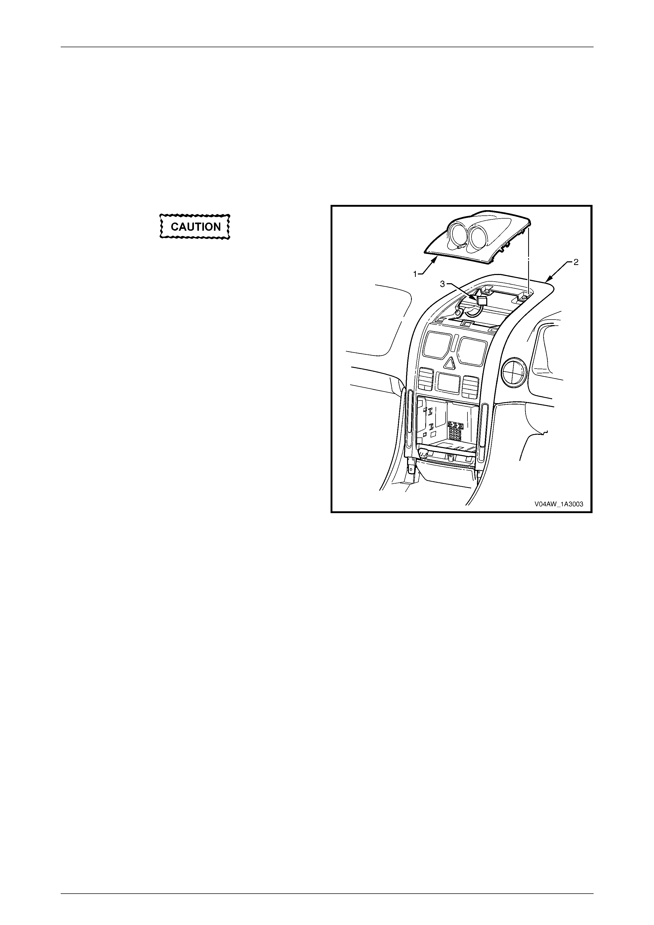
Remove
Take care not to mark or damage the
inclinometer assembly or the instrument
panel centre trim assembly.
1 Carefully prise the front edge of the inclinometer
assembly (1) and pull upward to disengage the
retaining clips at each corner from the centre trim
assembly (2).
NOTE
A fine flat-bladed screwdriver with the tip
wrapped in a shop rag may be used to prise the
front edge of the inclinometer assembly.
2 Disconnect the wiring connector P3 (3) from the
inclinometer assembly.
NOTE
The inclinometer assembly is illuminated
with incandescent bulbs. For replacement of the
inclinometer assembly bulbs, refer to
Section 12B Lighting System.
Figure 1A3 – 2
Instrument P anel and Console Page 1A3–6
Page 1A3–6
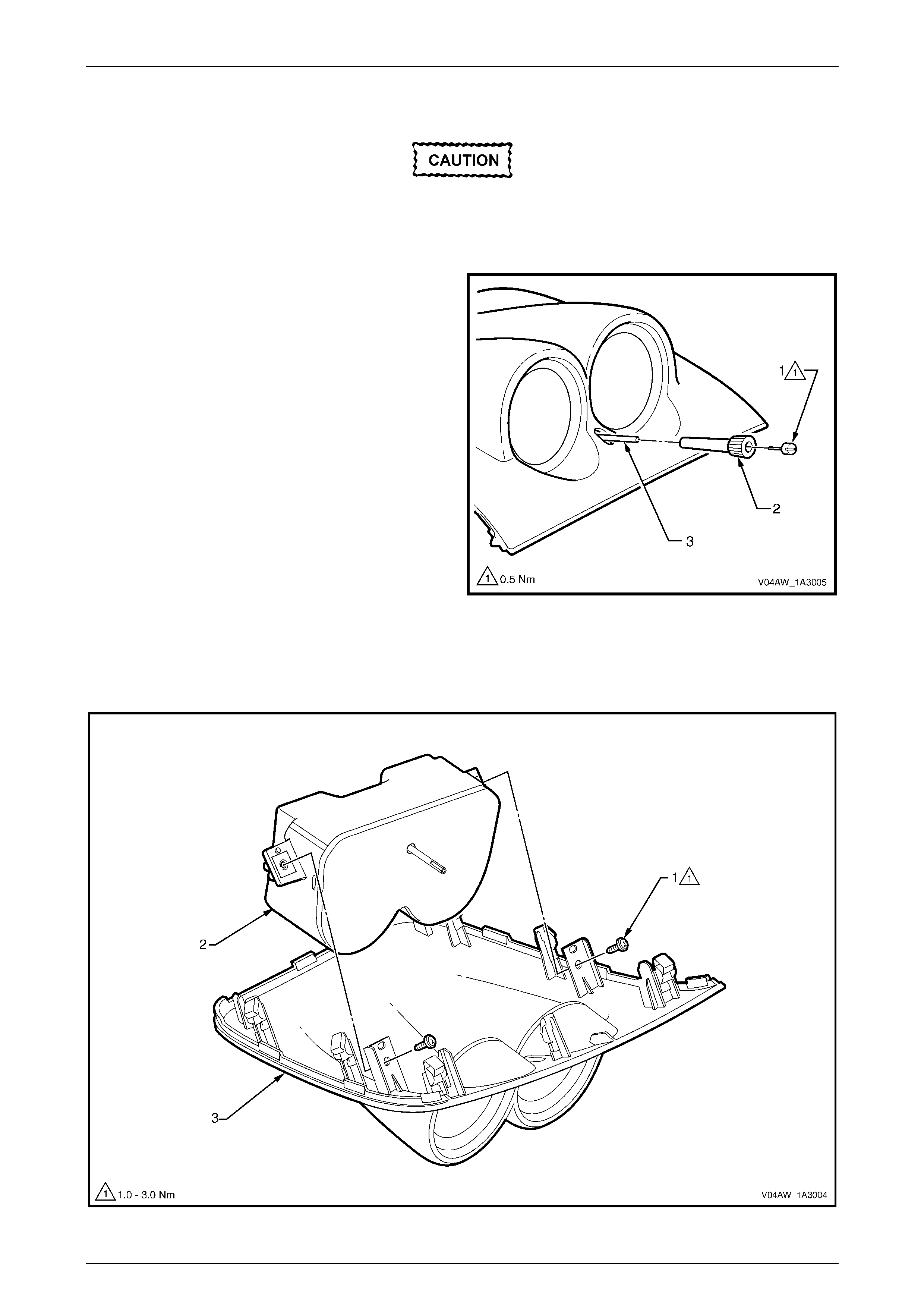
Disassemble
Except for removal from the inclinometer
assembly housing and the replacement of
bulbs, do not perform any further
disassembly of the inclinometer assembly.
1 Remove the screw (1) from the front of the
inclinometer assembly knob (2).
2 Remove the inclinometer assembly knob from the
shaft (3).
3 Place the screw and knob in a safe location.
Figure 1A3 – 3
4 Remove the two screws (1) attaching the inclinometer assembly (2) to the inclinometer assembly housing (3), refer
to Figure 1A3 – 4.
5 Remove the inclinometer assembly from the inclinometer assembly housing.
Figure 1A3 – 4

Instrument P anel and Console Page 1A3–7
Page 1A3–7
Reassemble
Reassembly of the inclinometer assembly is the reverse of the disassembly procedure, noting the following:
1 Tighten the screws to the specified torque.
Inclinometer assembly attaching screw
torque specific atio n ....................................1.0 – 3.0 Nm
Inclinometer assembly knob attaching screw
torque specific atio n .............................................0.5 Nm
Reinstall
Reinstallation of the inclinometer assembly is the reverse of the removal procedure.

Instrument P anel and Console Page 1A3–8
Page 1A3–8
3 Torque Wrench Specifications
Inclinometer Assembly Attaching Screw........................................1.0 – 3.0 Nm
Inclinometer Assembly Knob Attaching Screw........................................0.5 Nm