
Hood, Rear Com part ment Lid, Liftgate and Endgate Page 1A4–1
Page 1A4–1
Section 1A4
Hood, Rear Compartment Lid, Liftgate and
Endgate
ATTENTION
Before performing any service operation or other procedure described in this Section, refer to Section 00
Warnings, Cautions and Notes for correct workshop practices w ith regard to safety and/or property damage.
1 General Description............................................................................................................................... 3
1.1 Liftgate Assembly ..................................................................................................................................................3
Liftgate Assembly..................................................................................................................................................3
Liftgate Window Assembly....................................................................................................................................3
Liftgate Window Release Assembly.....................................................................................................................4
Rear Wiper and Rear Washer................................................................................................................................6
Rear Wiper Control Module...................................................................................................................................6
Liftgate Applique....................................................................................................................................................6
Liftgate Air Deflector Assembly and High Mount Stop Lamp Assembly...........................................................6
2 Service Operations................................................................................................................................ 7
2.1 Liftgate Window Lower Garnish...........................................................................................................................7
Remove ...................................................................................................................................................................7
Reinstall..................................................................................................................................................................7
2.2 Liftgate Lower Trim Panel .....................................................................................................................................8
Remove ...................................................................................................................................................................8
Reinstall..................................................................................................................................................................8
2.3 Liftgate Window Upper Garnish............................................................................................................................9
Remove ...................................................................................................................................................................9
Reinstall..................................................................................................................................................................9
2.4 Liftgate Window Release Assembly...................................................................................................................10
Remove .................................................................................................................................................................10
Disassemble.........................................................................................................................................................11
Liftgate Window Release Actuator...................................................................................................................11
Liftgate Window Latch Assembly .....................................................................................................................12
Liftgate Window Microswitch............................................................................................................................13
Reinstall................................................................................................................................................................13
2.5 Liftgate Applique Assembly................................................................................................................................14
Remove .................................................................................................................................................................14
Disassemble.........................................................................................................................................................15
Reassemble..........................................................................................................................................................15
Reinstall................................................................................................................................................................15
2.6 Liftgate Air Deflector Assembly..........................................................................................................................16
Remove .................................................................................................................................................................16
Disassemble.........................................................................................................................................................17
Reassemble..........................................................................................................................................................17
Reinstall................................................................................................................................................................17
2.7 Liftgate Window Assembly..................................................................................................................................18
Remove .................................................................................................................................................................18
Disassemble.........................................................................................................................................................20
Liftgate Window Striker and Handle.................................................................................................................20
Liftgate Window Strut Ball Stud........................................................................................................................21
Reinstall................................................................................................................................................................21

Hood, Rear Com part ment Lid, Liftgate and Endgate Page 1A4–2
Page 1A4–2
2.8 Liftgate Window Hinge ........................................................................................................................................22
Remove .................................................................................................................................................................22
Reinstall................................................................................................................................................................22
2.9 Liftgate Window Strut..........................................................................................................................................23
Remove .................................................................................................................................................................23
Reinstall................................................................................................................................................................23
2.10 Liftgate Window Upper Strut Bracket.................................................................................................................24
Remove .................................................................................................................................................................24
Reinstall................................................................................................................................................................24
2.11 Liftgate Window Weatherstrip ............................................................................................................................25
Remove .................................................................................................................................................................25
Reinstall................................................................................................................................................................25
2.12 Liftgate Assembly ................................................................................................................................................26
Remove .................................................................................................................................................................26
Disassemble.........................................................................................................................................................27
Reassemble..........................................................................................................................................................28
Reinstall................................................................................................................................................................28
Adjust....................................................................................................................................................................29
3 Torque Wrench Specifications........................................................................................................... 32
Hood, Rear Com part ment Lid, Liftgate and Endgate Page 1A4–3
Page 1A4–3
1 General Description
With the following exceptions, MY 2004 AWD Wagon Hood, Rear Compartment Lid, Liftgate and Endgate information
carries over from MY 2003 VY Wagon vehicles:
• Liftgate assembly
For Hood, Rear Compartment Lid, Liftgate and Endgate information not contained within this Section, refer to
Section 1A4 Hood, Rear Compartment Lid, Liftgate and Endgate in the MY 2003 VY and V2 Series Service Information.
1.1 Liftgate Assembly
Liftgat e Assembly
A new liftgate assembly is fitted to AWD wagon vehicles. The liftgate assembly consists of an outer panel that is
hemmed over the inner panel at the outer edges. The liftgate assembly is fitted with a new liftgate wi ndow assembly, a
liftgate window upper garnish, a liftgate window lower garnish and a liftgate window weatherstrip.
Two gas struts are used to assist the opening of the liftgate assembly and to hold the liftgate assembly in the open
position. Similarly, two struts are used to assist the opening of the liftgate window assembly.
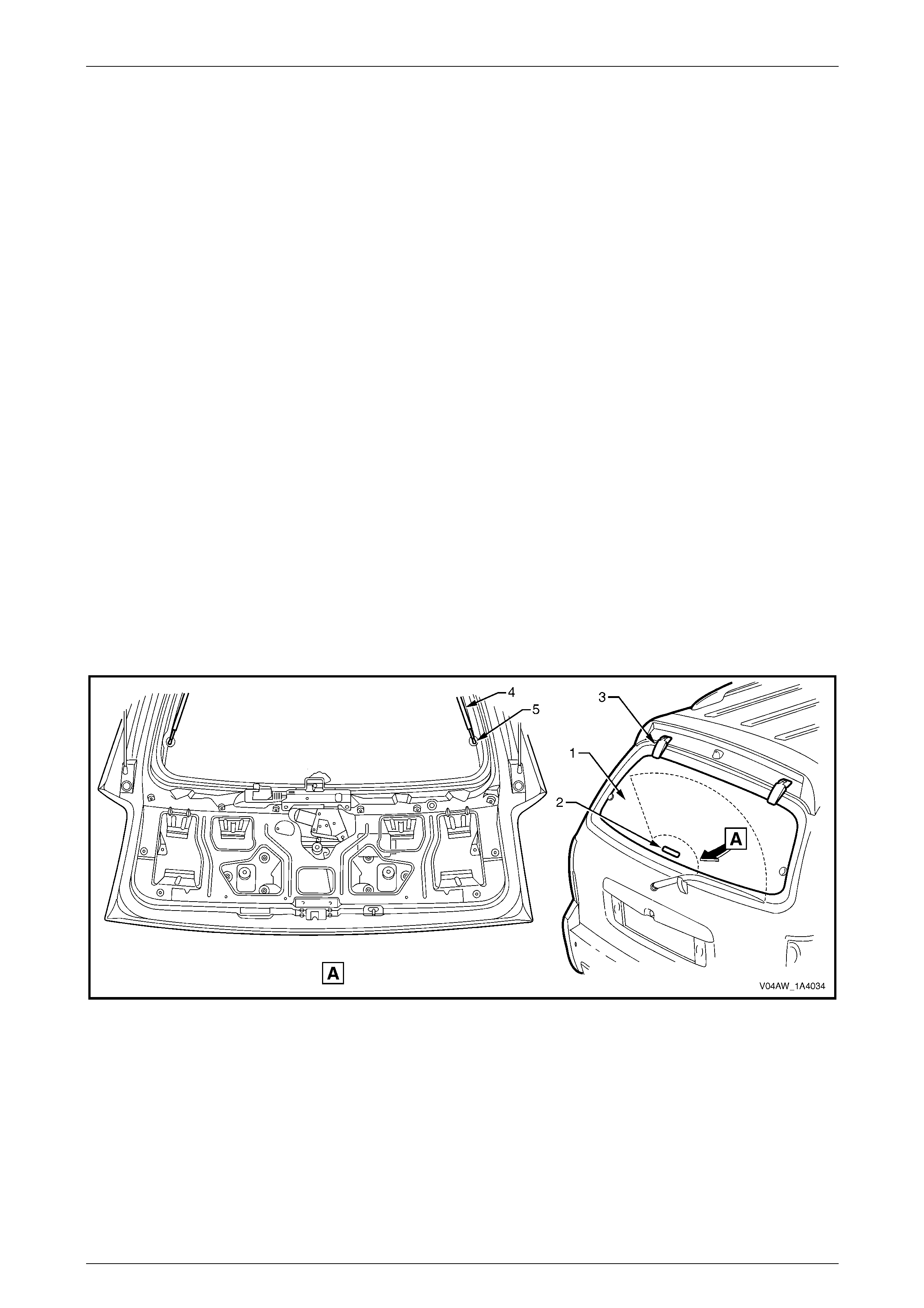
Liftgate Window Assembly
The hinged liftgate window assembly can be released and swung open in an upward direction while the liftgate
assembly remains closed. The liftgate window assembly consists of the following components:
• Liftgate window glass (1), refer to Figure 1A4 – 1
• Liftgate window striker and handle (2)
• Liftgate window hinge (3)
• Liftgate window struts (4) and liftgate window strut ball studs (5)
Figure 1A4 – 1
Hood, Rear Com part ment Lid, Liftgate and Endgate Page 1A4–4
Page 1A4–4
When the rear wiper has been operating and
before turning off the ignition switch, ensure
that the rear wiper arm is parked on the rear
wiper arm ramp. If this is not done, rear w iper
arm will remain on the liftgate window glass
and vehicle damage could occur when the
liftgate window assembly is opened.
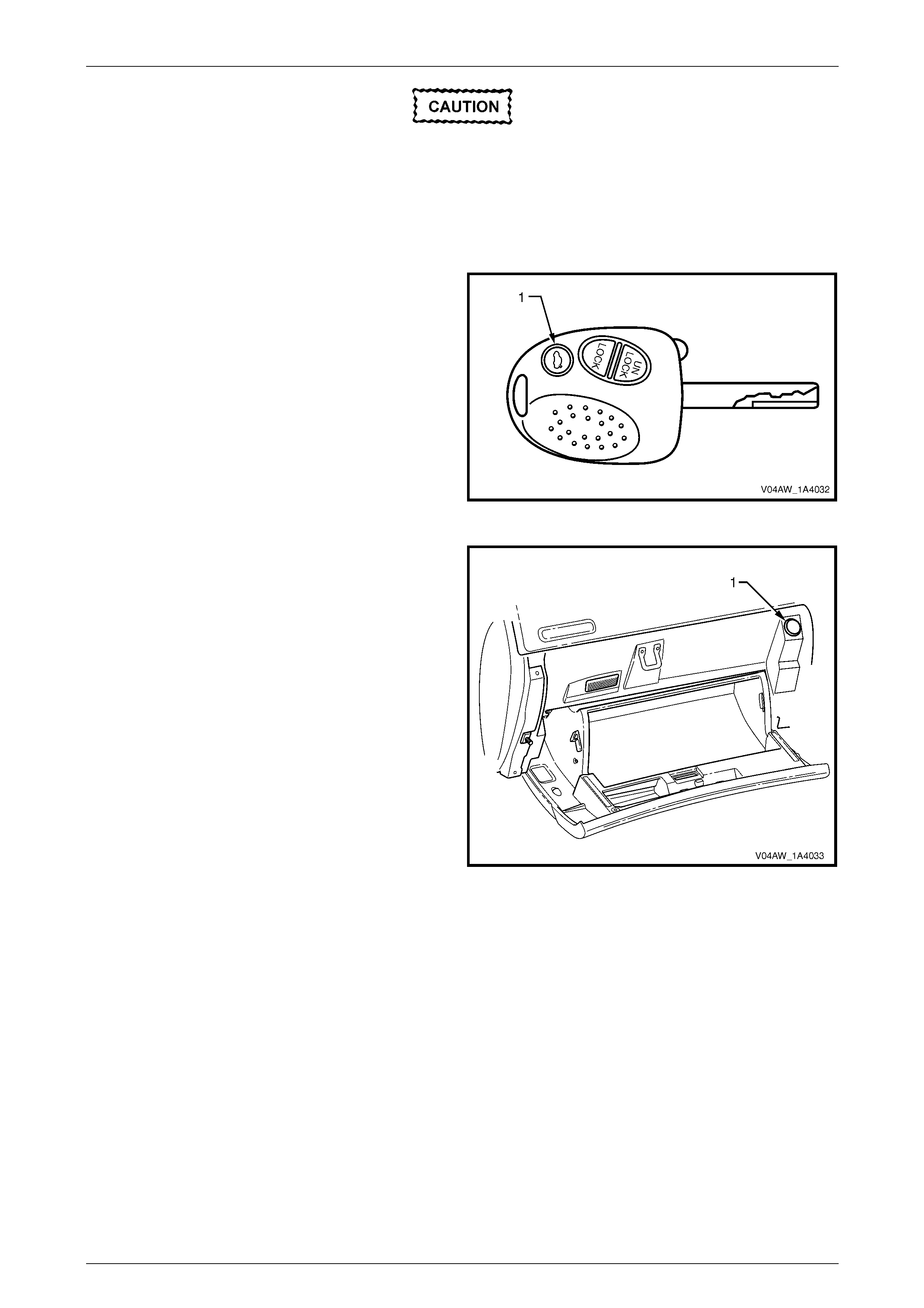
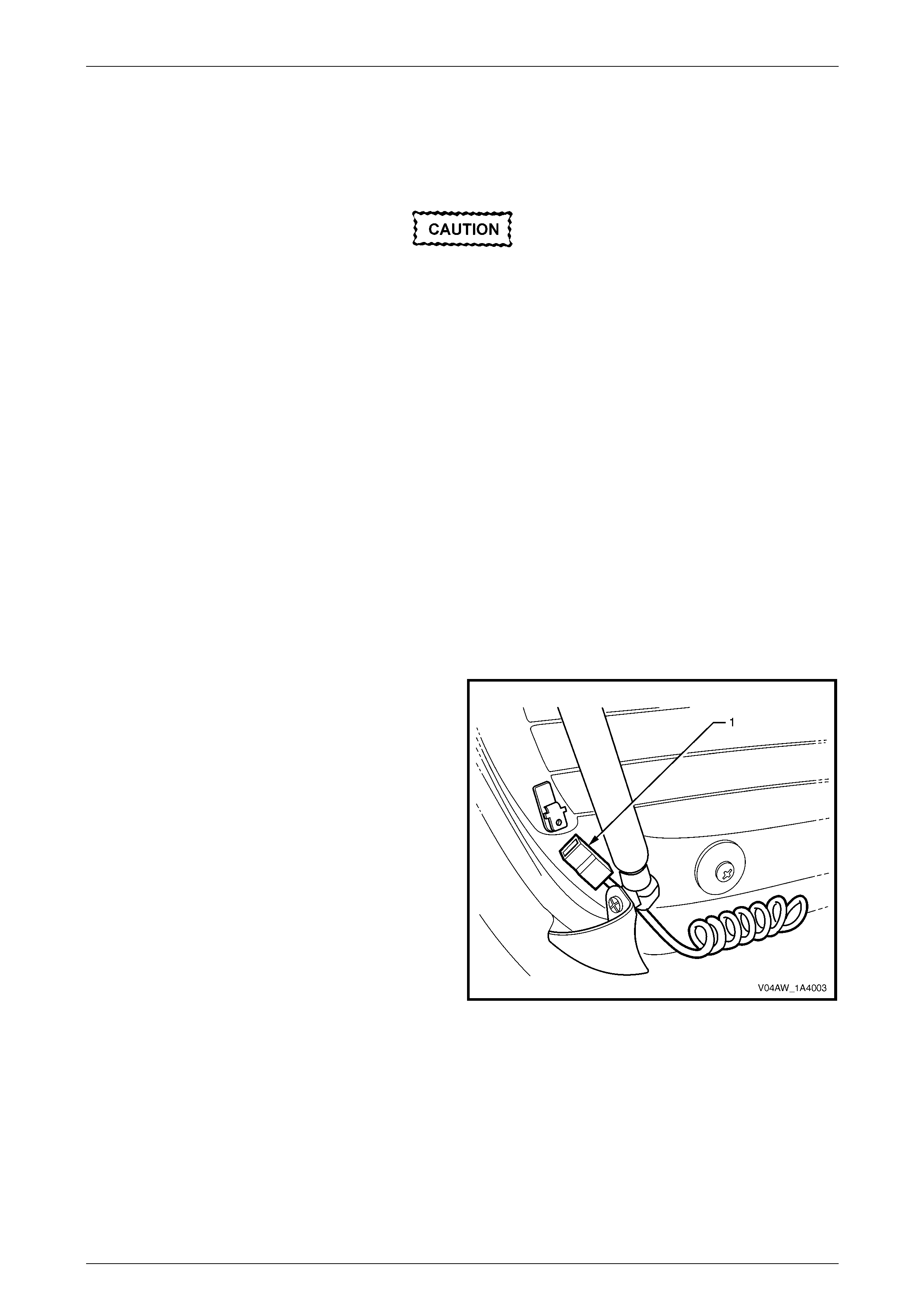
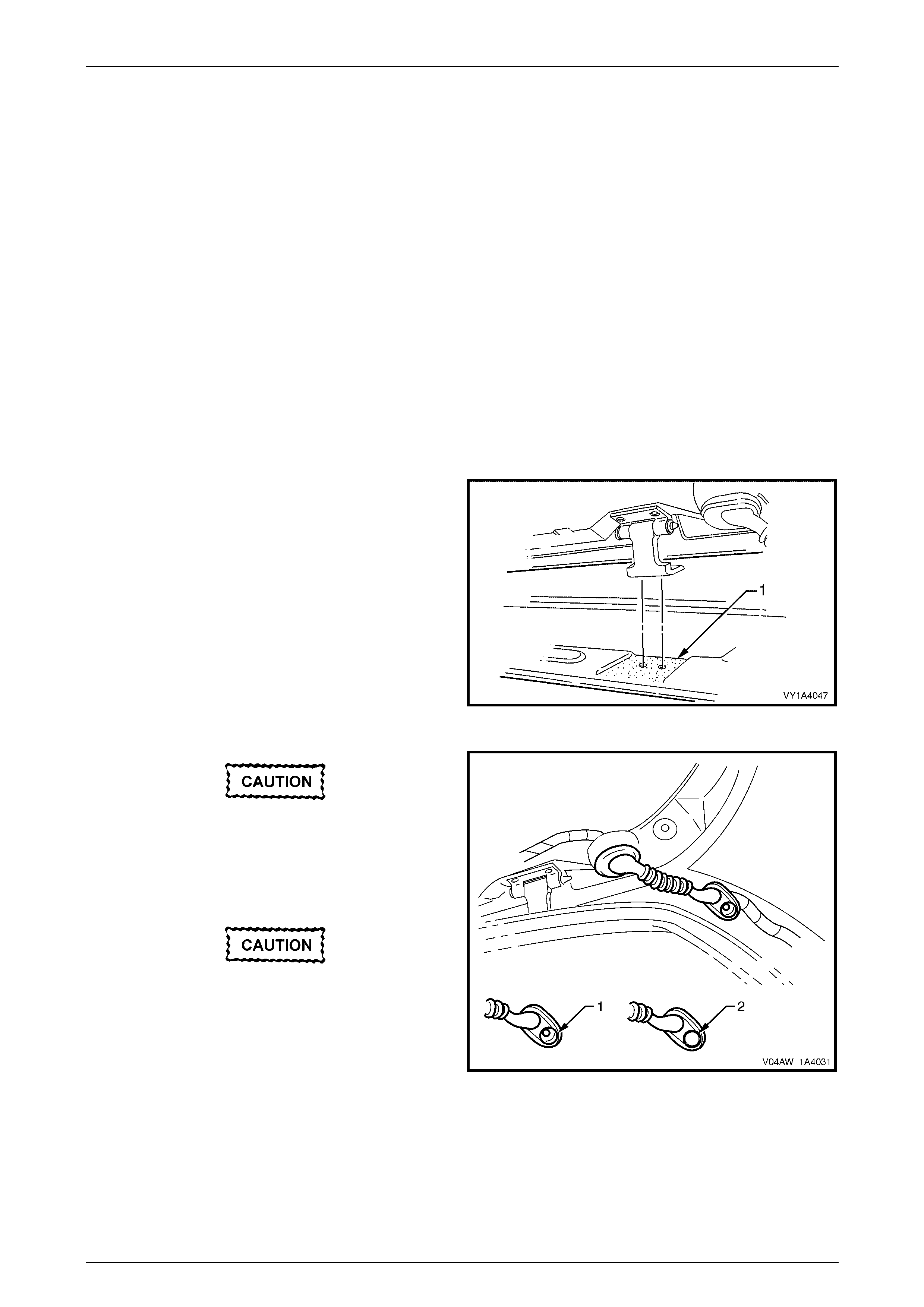
The liftgate window latch can be released by pressing the
liftgate window release button (1) on the remote coded key.
For remote coded key service operations, refer to
Section 12J Body Control Module.
Figure 1A4 – 2
The liftgate window latch can also be released by opening
the instrument panel compartment and then pressing the
liftgate window release button (1).
For liftgate window release button service operations, refer
to Section 1A3 Instrument Panel and Console.
Figure 1A4 – 3
Liftgat e Wi ndow Release Assembly
Refer to Figure 1A4 – 4 for the following.
A liftgate window release assembly (1) is fitted to the liftgate assembly. When the rear wiper control module (2) receives
a command from the BCM to release the liftgate window latch (3):
1 The rear wi per control module checks that the rear wiper is not operating. If the rear wiper is operating, the
command is ignored.
2 The rear wiper control module energises the liftgate window release actuator.
3 Through a connecting rod, the liftgate window release actuator releases the liftgate window latch.
Hood, Rear Com part ment Lid, Liftgate and Endgate Page 1A4–5
Page 1A4–5
Figure 1A4 – 4
The liftgate window release assembly incorporates the
following:
• Liftgate window latch (1)
• Liftgate window microswitch (2)
The liftgate window microswitch provides position status of
the liftgate window assembly to the rear wiper control
module and switches the rear compartment lamp.
Figure 1A4 – 5
The liftgate switch (1) provides position status of the liftgate
assembly to the rear wiper control module and switches the
rear compartment lamp.
For further information on the rear wiper control module,
refer to Section 12N Wipers, Washers and Horn.
For further information on the liftgate switches, refer to
Section 12B Lighting System.
For diagnosis of the liftgate window release assembly, refer
to Section 12N Wipers, Washers and Horn.
Figure 1A4 – 6

Hood, Rear Com part ment Lid, Liftgate and Endgate Page 1A4–6
Page 1A4–6
Rear Wiper and Rear Washer
A new rear wiper motor assembly (1) and rear wiper arm (2) are fitted to the liftgate assembly. When the rear wiper arm
is not in operation, it is parked below the liftgate window assembly on the rear wiper arm ramp (3), refer to
Figure 1A4 – 7. This parking position enables the liftgate window assembly to be swung open in an upward direction
with the rear wiper arm being off the liftgate window glass.
For rear wiper arm assembly, rear wiper motor assembly, rear wiper ramp and rear wi per control module service
operations, refer to Section 12N Wipers, Washers and Horn.
Figure 1A4 – 7
Rear Wiper Control Module
The rear wi per control module controls the operation of the rear wiper and the liftgate window release actuator. For
additional information and diagnosis of the rear wiper control module, refer Section 12N Wipers, Washers and Horn.
Liftgat e Applique
The liftgate applique assembly combines the functionality of the liftgate handle assembly and a licence plate surround. It
incorporates the following illumination:
• New backup lamps, refer to Section 12B Lighting System.
• Carry-over licence lamp assemblies, refer to 2.5 Liftgate Applique Assembly
Liftgat e Air Deflector Assembl y and High Mount St op Lamp Assembly
A new high mount stop lamp assembly is incorporated into a new liftgate air deflector assembly. For service operations,
refer to 2.6 Liftgate Air Deflector Assembly.
Hood, Rear Com part ment Lid, Liftgate and Endgate Page 1A4–7
Page 1A4–7
2 Service Operations
2.1 Liftgate Window Lower Garnish
LT Section No. – 14-500
Remove
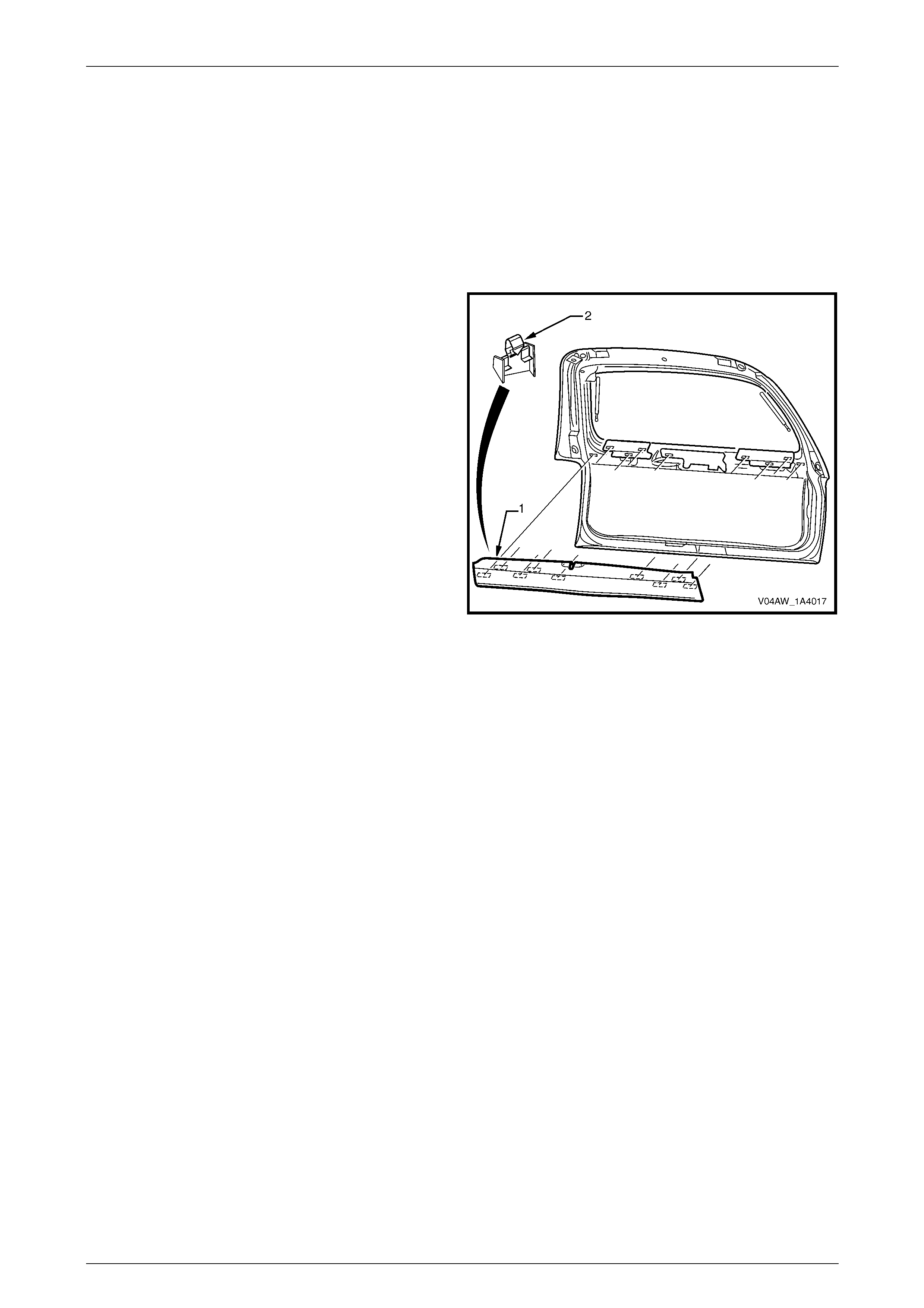
1 Beginning at one end, insert a flat-bladed screwdriver
behind the liftgate window lower garnish (1), push on
the clip (2), in nine places, and carefully prise the
liftgate window lower garnish from the liftgate
assembly.
2 If required, prise the clips from the liftgate window
lower garnish using a flat-bladed screwdriver.
Figure 1A4 – 8
Reinstall
Reinstallation of the liftgate window lower garnish is the reverse of the removal procedure, noting the following:
1 Ensure that the clips are correctly oriented.
2 Align the clips with the corresponding holes in the liftgate assembly and clip the liftgate window lower garnish onto
the liftgate assembly.
Hood, Rear Com part ment Lid, Liftgate and Endgate Page 1A4–8
Page 1A4–8
2.2 Liftgate Lower Trim Panel
LT Section No. – 14-500
Remove
1 If required, remove the liftgate window lower garnish, refer to 2.1 Liftgate Window Lower Garnish .
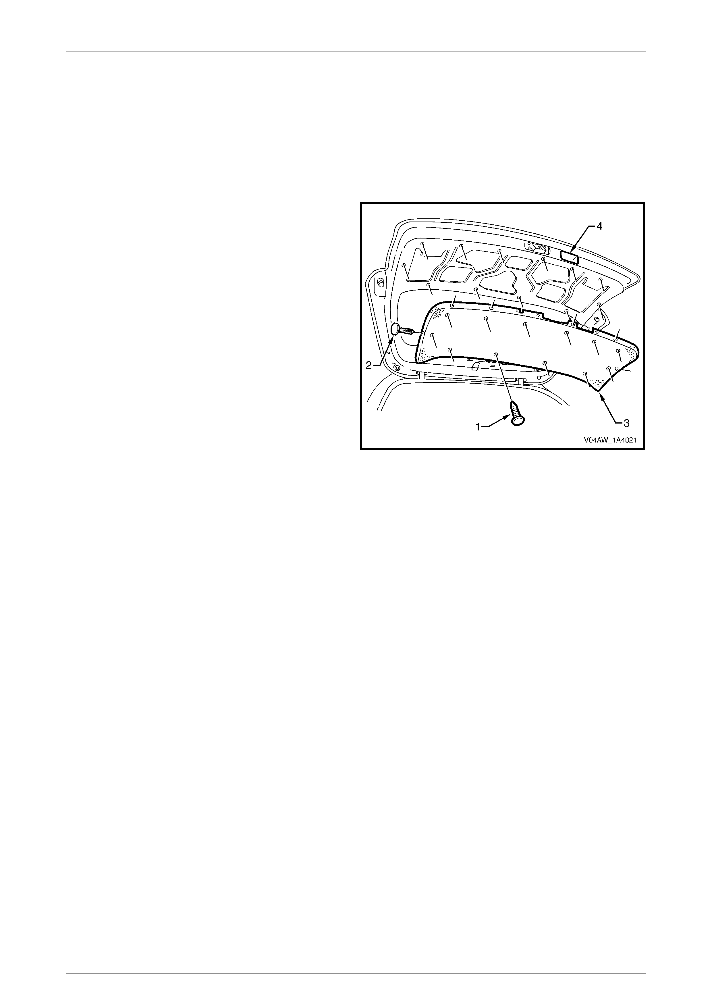
2 Using a suitable trim clip removal tool, carefully prise
the retainers (1), in twelve places, and retainers (2), in
six places, attaching the liftgate lower trim panel (3) to
the liftgate assembly.
3 Remove the liftgate lower trim panel from the liftgate
assembly by sliding it from under the liftgate inside
handle (4).
Figure 1A4 – 9
Reinstall
Reinstallation of the liftgate lower trim panel is the reverse of the removal procedure.
Hood, Rear Com part ment Lid, Liftgate and Endgate Page 1A4–9
Page 1A4–9
2.3 Liftgate Window Upper Garnish
LT Section No. – 14-500
Remove
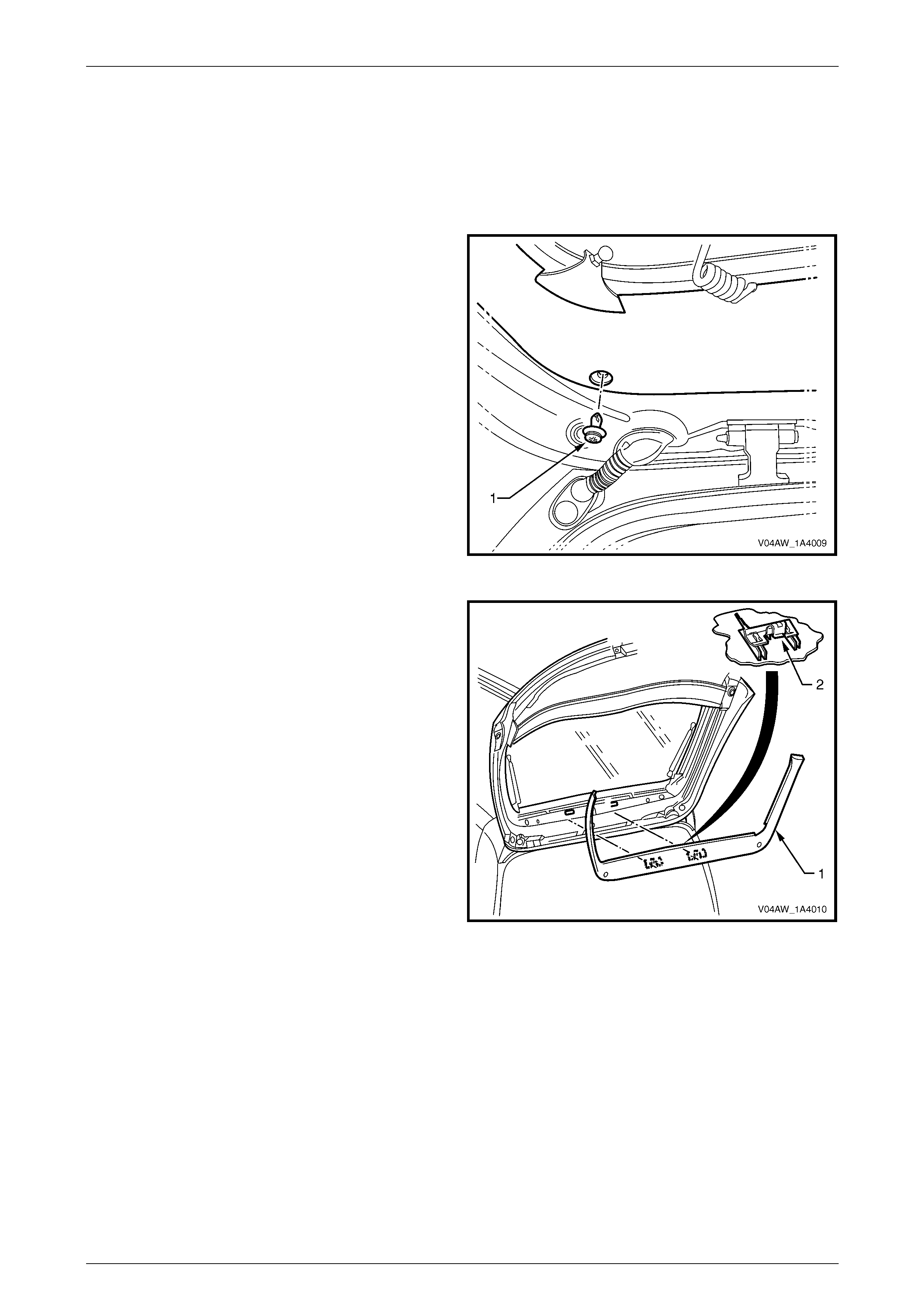
1 Remove the retainer (1), in one place each side, from
the liftgate window upper garnish.
Figure 1A4 – 10
2 Insert a flat-bladed screwdriver behind the liftgate
window upper garnish (1), push on the clip tab (2), in
two places, and carefully prise the liftgate window
upper garnish from the liftgate assembly.
3 If required, prise the clips from the liftgate window
upper garnish using a flat-bladed screwdriver.
4 Disengage both ends of the liftgate window upper
garnish from behind the liftgate window lower garnish
Figure 1A4 – 11
Reinstall
Reinstallation of the liftgate window upper garnish is the reverse of the removal procedure, noting the following:
1 Ensure that the clips are correctly oriented.
2 Align the clips with the corresponding holes in the liftgate assembly and clip the liftgate window upper garnish onto
the liftgate assembly.
Hood, Rear Com part ment Lid, Liftgate and Endgate Page 1A4–10
Page 1A4–10
2.4 Liftgate Window Release Assembly
LT Section – XX-XXX
NOTE
The liftgate window microswitch and liftgate
window release actuator can be electrically
tested without removing them from the vehicle by
removing the liftgate lower trim panel. To test
these components, refer to the disassembly
procedure in this Section.
Remove
1 Remove the power door locks, theft horn and power windows fuse F20 from the passenger compartment fuse and
relay panel assembly, refer to Section 12O Fuses, Relays and Wi ring Harnesses.
2 Remove the liftgate wi ndow lower garnish, refer to 2.1 Liftgate Window Lower Garnish.
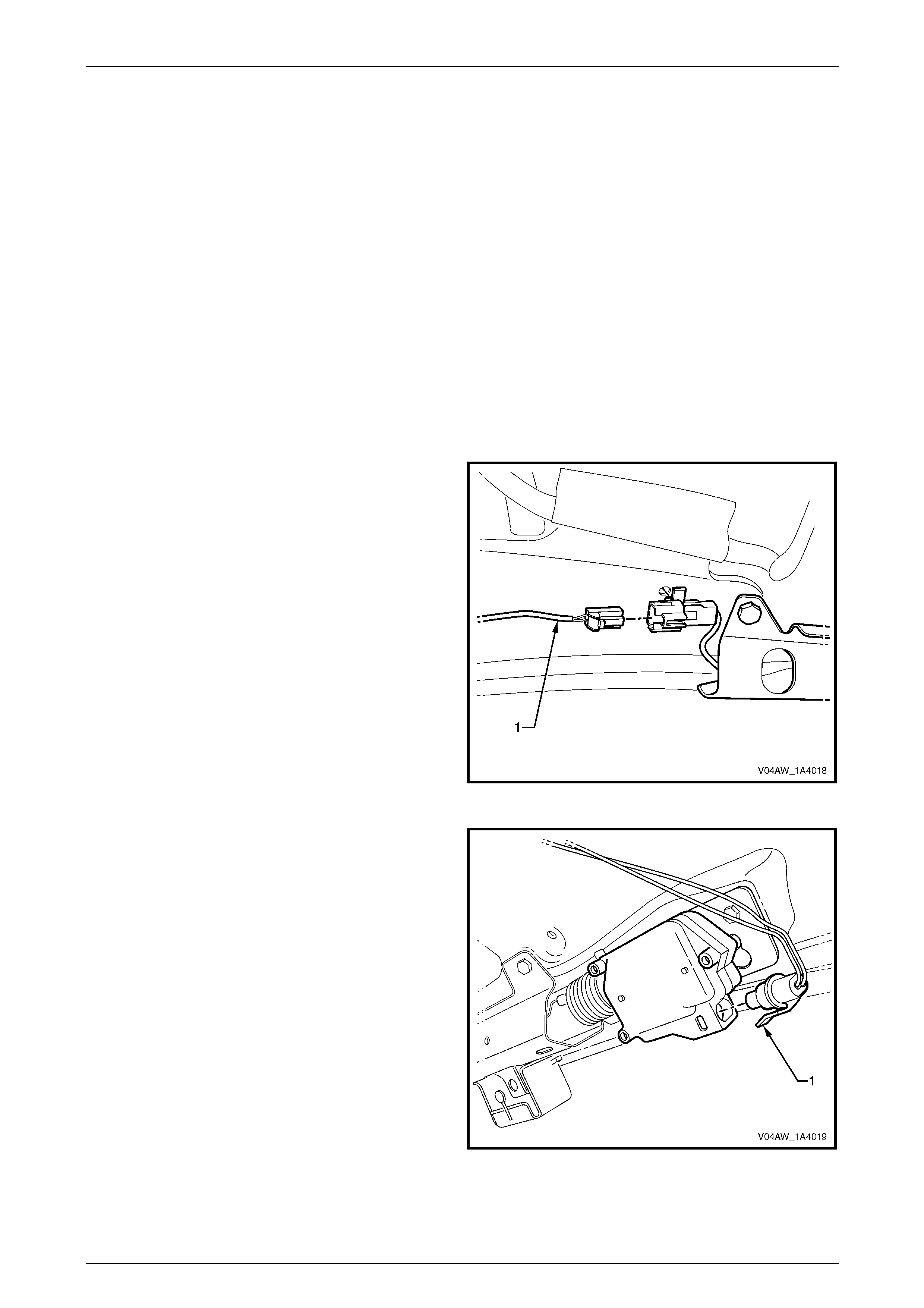
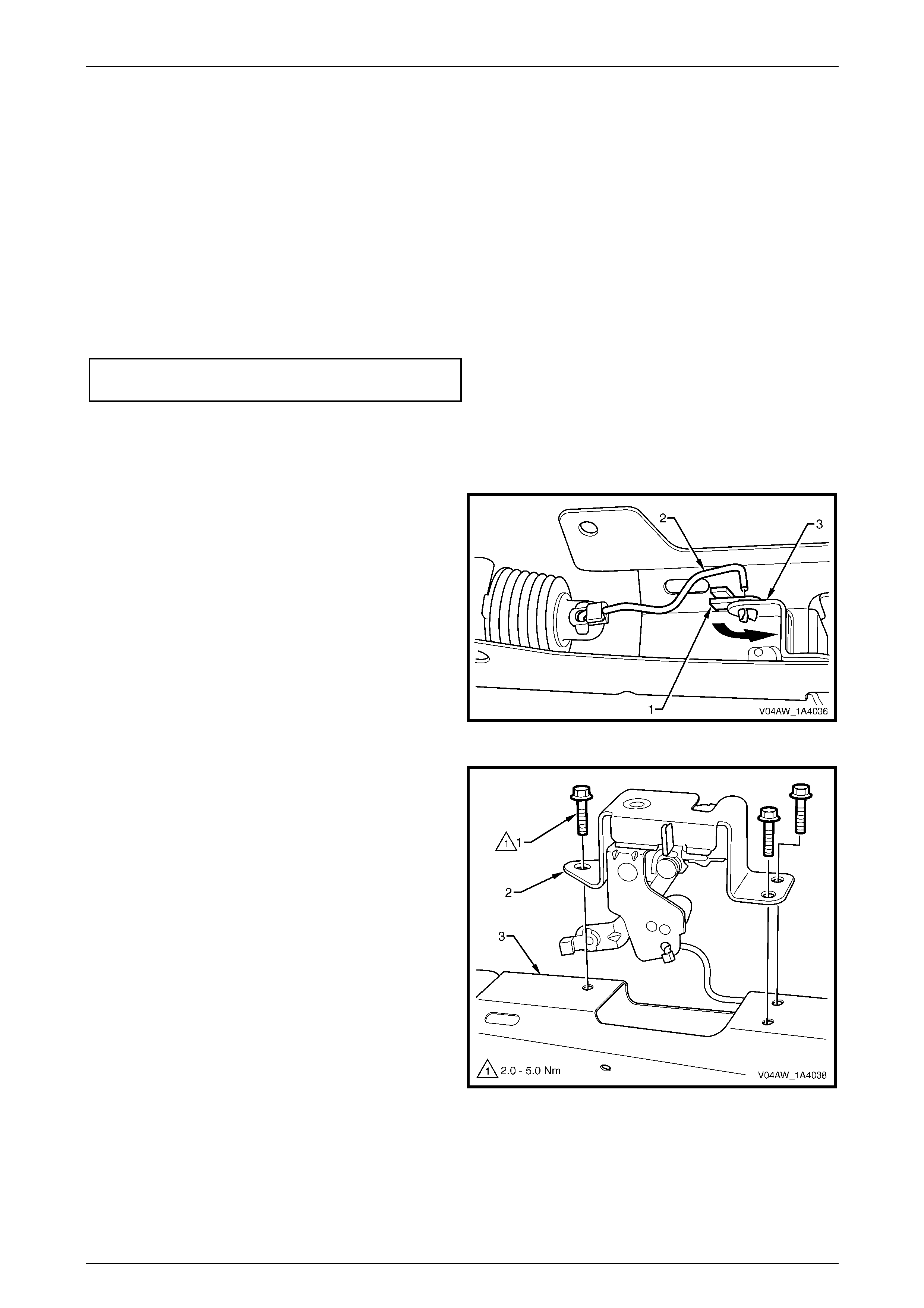
3 Disconnect the liftgate window microswitch
connector (1).
Figure 1A4 – 12
4 Disconnect liftgate window release actuator
connector (1).
Figure 1A4 – 13
Hood, Rear Com part ment Lid, Liftgate and Endgate Page 1A4–11
Page 1A4–11
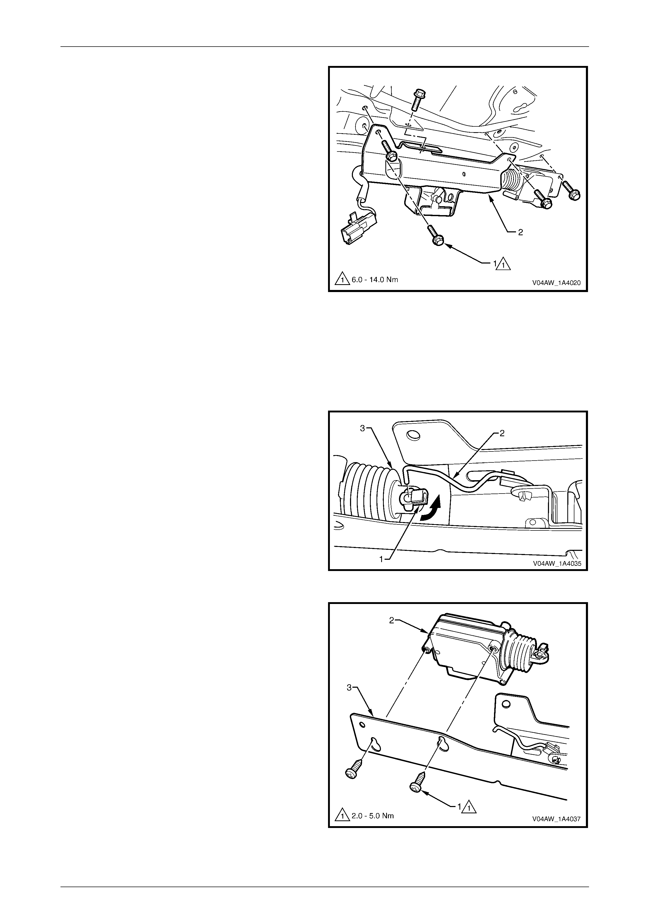
5 Remove the five screws (1) attaching the liftgate
window release assembly (2) to the liftgate assembly.
6 Remove the liftgate window release assembly.
Figure 1A4 – 14
Disassemble
Liftgate Window Release Actuator
Remove
1 Rotate the clip (1) and remove the connecting rod (2)
from the liftgate window release actuator (3).
Figure 1A4 – 15
2 Loosen the screws (1), in two places, attaching the
liftgate window release actuator (2) to the liftgate
window release assembly (3). Remove the actuator.
3 If required, remove the screws from the actuator.
Figure 1A4 – 16
Hood, Rear Com part ment Lid, Liftgate and Endgate Page 1A4–12
Page 1A4–12
Test
1 Check that the plunger of the liftgate window release actuator can move freely.
2 Using a multimeter, check that the resistance across the terminals of the liftgate window release actuator does not
indicate either an open circuit or a short circuit.
3 Check that when ground is connected to pin B and battery voltage is applied to pin A, the plunger of the liftgate
window release actuator is extended.
Reinstall
Reinstallation of the liftgate window release actuator is the reverse of the removal procedure, noting the following:
1 Ensure that the screws are seated in the narrow end of the keyhole slots.
2 Tighten the screws to the correct torque specification.
Liftgate window release actuator attaching
screw torque specification..........................2.0 – 5.0 Nm
Liftgate Window Latch Assembly
Remove
1 Rotate the clip (1) and remove the connecting rod (2)
from the liftgate window latch assembly (3).
Figure 1A4 – 17
2 Remove the screws (1), in three places, attaching the
liftgate window latch assembly (2) to the liftgate
window release assembly (3).
Figure 1A4 – 18
Hood, Rear Com part ment Lid, Liftgate and Endgate Page 1A4–13
Page 1A4–13
Reinstall
Reinstallation of the liftgate window latch assembly is the reverse of the removal procedure, noting the following:
1 Tighten the screws to the correct torque specification.
Liftgate window latch assembly attaching
screw torque specification..........................2.0 – 5.0 Nm
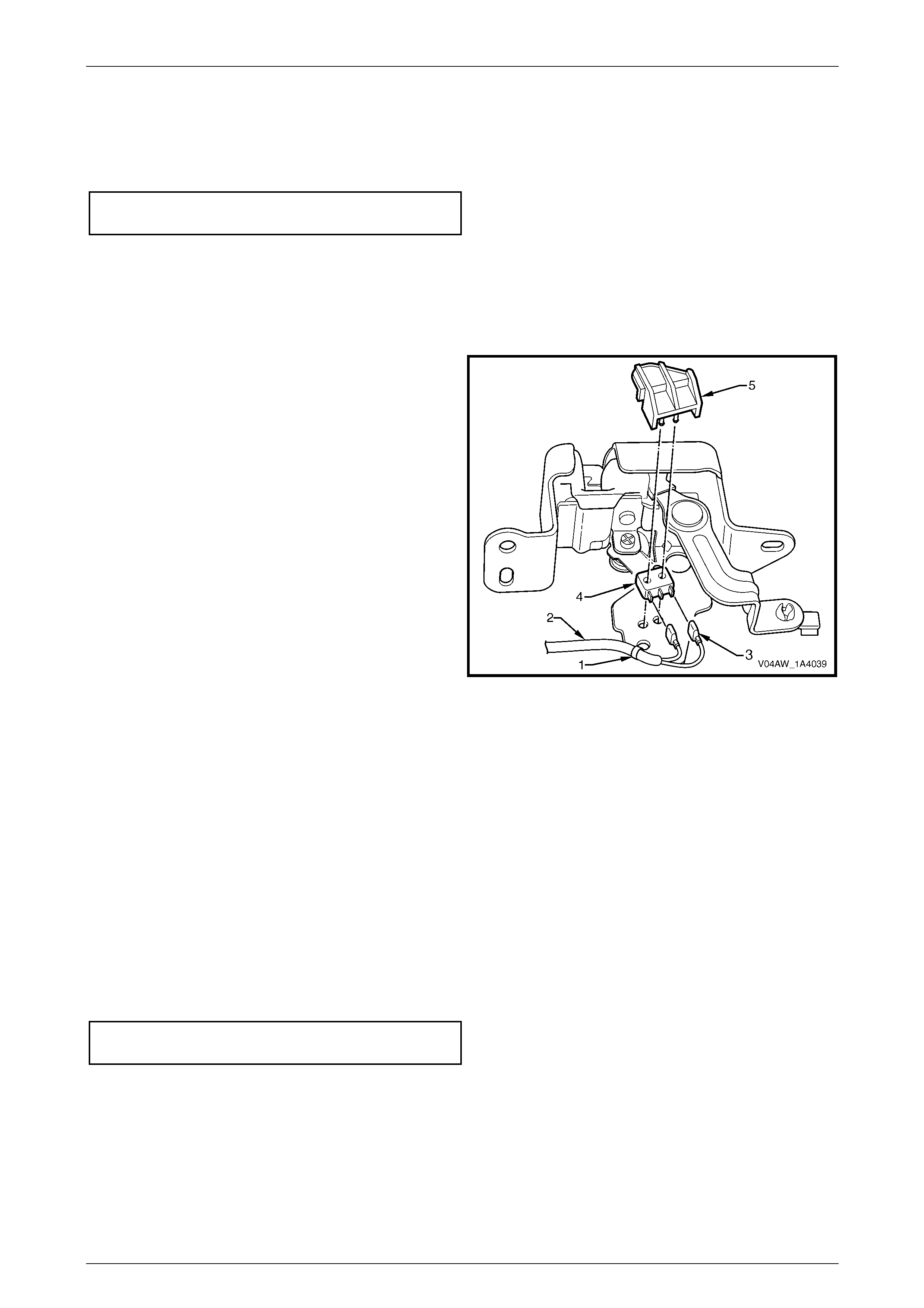
Liftgate Window Microswitch
Remove
1 If required, remove the liftgate window latch assembly.
2 If required, cut the cable tie (1) to enable removal of
the liftgate window microswitch harness (2).
3 Disconnect the liftgate window microswitch harness
from the outer terminals (3) of the liftgate window
microswitch (4).
4 Unclip the liftgate window microswitch retainer (5) and
remove the microswitch.
Figure 1A4 – 19
Reinstall
Reinstallation of the liftgate window microswitch is the reverse of the removal procedure.
Test
1 Using a multimeter, check that when the liftgate window latch assembly is in the closed position the resistance of
the microswitch indicates an open circuit.
2 Using a multimeter, check that when the liftgate window latch assembly is in the open position the resistance of
the microswitch indicates continuity.
Reinstall
Reinstallation of the liftgate window release assembly is the reverse of the removal procedure, noting the following:
1 Tighten the screws to the correct torque specification.
Liftgate window release assembly attaching
screw torque specification........................6.0 – 14.0 Nm
2 Check the operation of the liftgate window release actuator and the liftgate window latch assembly prior to
installing the trim components.
Hood, Rear Com part ment Lid, Liftgate and Endgate Page 1A4–14
Page 1A4–14
2.5 Liftgate Applique Assembly
LT Section No. – 02-385
Remove
1 If required, first remove the following components:
a Liftgate window lower garnish, refer to 2.1 Liftgate Window Lower Garnish
b Liftgate lower trim panel, refer to 2.2 Liftgate Lowe r Trim Panel
2 Remove the fusible link F102 from the engine compartment fuse and relay panel assembly, refer to Section 12O
Fuses, Relays and Wiring Harnesses.
3 Remove the rear wiper control module, refer to Section 12N, 2.5 Rear Wiper Control Module.
4 Remove both of the backup lamp bulbs from their socket assemblies. To remove a bulb, press the bulb and then
rotate it anticlockwise. Inspect the backup lamp socket assembly seals for damage and replace if necessary. For
further information on backup lamp sockets and bulbs, refer to Section 12B, 2.3 Backup Lamp s .
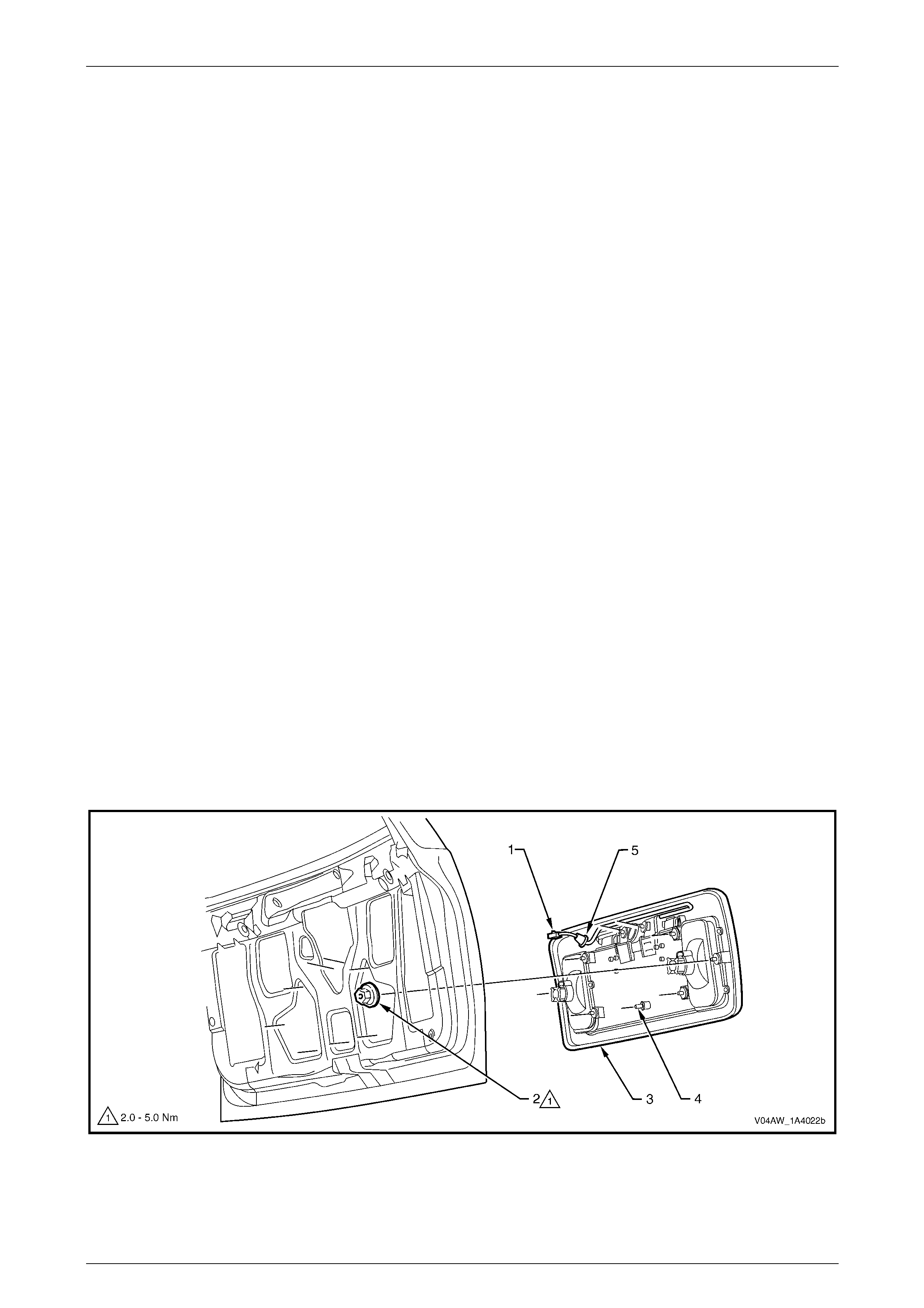
5 Disconnect the licence plate lamp wiring connector (1) from within the liftgate assembly cavity, refer to
Figure 1A4 – 20.
6 From within the liftgate assembly cavity, remove the nuts (2), in eight places, attaching the liftgate applique
assembly (3) to the liftgate assembly.
NOTE
The two top inner nuts also attach the liftgate
applique push-button assembly. The liftgate
applique push-button assembly will be loose and
may fall out. For further information on the
push-button assembly, refer to Section 1A4, 4.6
Liftgate Handle Push Button Assembly in the
MY 2003 VY and V2 Series Service Information.
7 Prise the pin (4) at the bottom of the liftgate applique assembly from the retainer.
8 Partially remove the applique assembly, remove the licence plate lamp wiring harness grommet (5) and withdraw
the licence plate lamp wiring harness.
9 Remove the applique assembly.
Figure 1A4 – 20
Hood, Rear Com part ment Lid, Liftgate and Endgate Page 1A4–15
Page 1A4–15
Disassemble
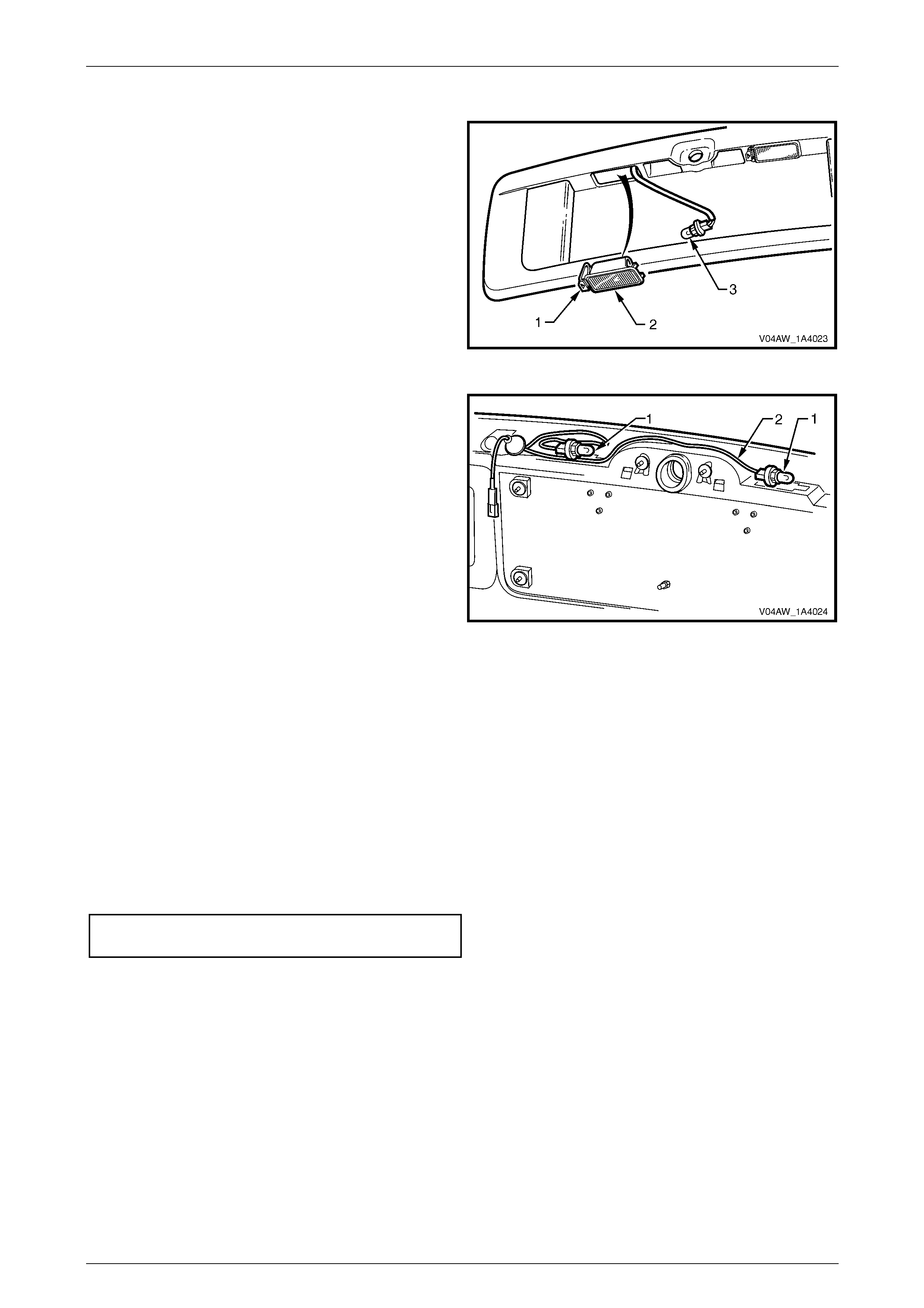
1 Push the tab (1) and remove the rear licence lamp
housing (2) from the liftgate applique assembly.
2 Rotate the bulb socket (3) and remove it from the rear
licence lamp housing.
3 Repeat for the remaining lamp housing.
Figure 1A4 – 21
4 Pass each of the two bulb sockets (1) through the
aperture in the liftgate applique assembly. Remove
the licence plate lamp wiring harness (2).
5 If required, remove both of the backup lamp
assemblies, refer to Section 12B, 2.3 Backup Lamps
Figure 1A4 – 22
Reassemble
Reassembly of the liftgate applique assembly is the reverse of the disassembly procedure, noting the following:
1 Ensure that the licence plate lamp wiring harness (1) is routed so that it clears the push-button assembly and the
edge of the applique assembly, refer to Figure 1A4 – 22.
Reinstall
Reinstallation of the liftgate applique assembly is the reverse of the removal procedure, noting the following:
1 Ensure that the applique assembly does not pinch the licence plate lamp wiring harness.
2 Tighten the nuts to the correct torque specification.
Liftgate applique assembly attaching nut
torque specification....................................2.0 – 5.0 Nm
Hood, Rear Com part ment Lid, Liftgate and Endgate Page 1A4–16
Page 1A4–16
2.6 Liftgate Air Deflector Assembly
LT Section No. – 10-350
Remove
1 Remove the liftgate window upper garnish, refer to 2.3 Liftgate Window Upper Garnish.
2 Remove the plug (1) from both sides of the liftgate assembly, refer to Figure 1A4 – 23.
3 Remove the plug (2) from the centre of the liftgate assembly.
4 Disconnect the high mount stop lamp wiring connector (3).
Figure 1A4 – 23
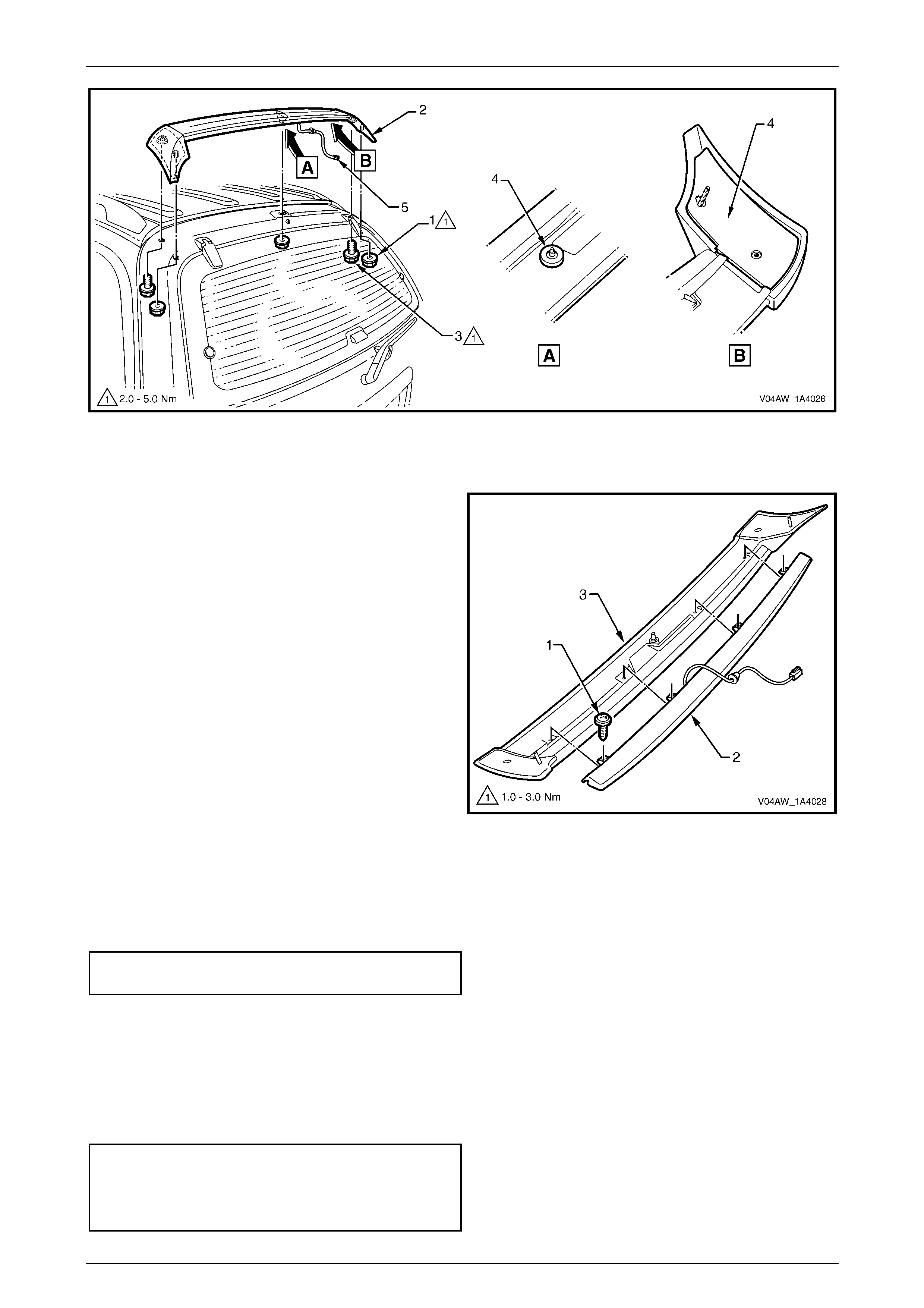
5 Using a tube socket, remove the nuts (1), in three places, attaching the liftgate air deflector assembly (2) to the
liftgate assembly, refer to Figure 1A4 – 24.
6 Remove the screws (3), in two places, attaching the air deflector assembly to the liftgate assembly.
Take care not to damage the seals (4) when
removing the liftgate air deflector assembly,
as they are not serviced.
7 Remove the liftgate air deflector assembly.
8 Remove the grommet and withdraw the wiring harness (5).
Hood, Rear Com part ment Lid, Liftgate and Endgate Page 1A4–17
Page 1A4–17
Figure 1A4 – 24
Disassemble
1 Remove the screws (1), in four places, attaching the
high mount stop lamp assembly (2) to the liftgate air
deflector assembly (3).
Figure 1A4 – 25
Reassemble
Reassembly of the liftgate air deflector assembly is the reverse of the disassembly procedure, noting the following:
1 Tighten the screws to the correct torque specification.
High mount stop lamp assembly
attaching screw torque specification.......... 1.0 – 3.0 Nm
Reinstall
Reinstallation of the liftgate air deflector assembly is the reverse of the removal procedure, noting the following:
1 Prior to installation, ensure that the seals are not damaged. If in doubt, apply a small amount of non-hardening
sealer.
2 Tighten the fasteners to the correct torque specification.
Liftgate air deflector assembly
attaching nut torque specification ..............2.0 – 5.0 Nm
Liftgate air deflector assembly
attaching screw torque specification.......... 2.0 – 5.0 Nm
Hood, Rear Com part ment Lid, Liftgate and Endgate Page 1A4–18
Page 1A4–18
2.7 Liftgate Window Assembly
LT Section – 11-030
Take care to ensure that the liftgate window
glass does not strike an object. Chipped
edges can lead to subsequent breakage of
the liftgate window glass.
Remove
1 Ensure that the rear wiper arm is off the liftgate window glass and in the parked position on the rear wiper arm
ramp. To move the rear wiper arm onto the rear wiper arm ramp:
a Ensure that the liftgate assembly and the liftgate window assembly are closed.
b Turn the ignition on.
c Move the rear wiper switch to initiate wiping of the rear wiper arm and move the rear wiper switch to the OFF
position.
d Wait until the wipe operation stops and the rear wiper arm moves to the park position on the rear wiper arm
ramp.
e Turn the ignition off.
2 Press the rear compartment release button on the remote coded key to unlock the liftgate window assembly.
Alternatively, press the rear compartment release button that is located in the instrument panel compartment.
3 Open the liftgate window assembly to relieve the tension in the liftgate window strut.
4 Disconnect the demister connector (1) from each side.
Figure 1A4 – 26
Hood, Rear Com part ment Lid, Liftgate and Endgate Page 1A4–19
Page 1A4–19
Have an assistant support the liftgate
window assembly while disconnecting the
liftgate window struts.
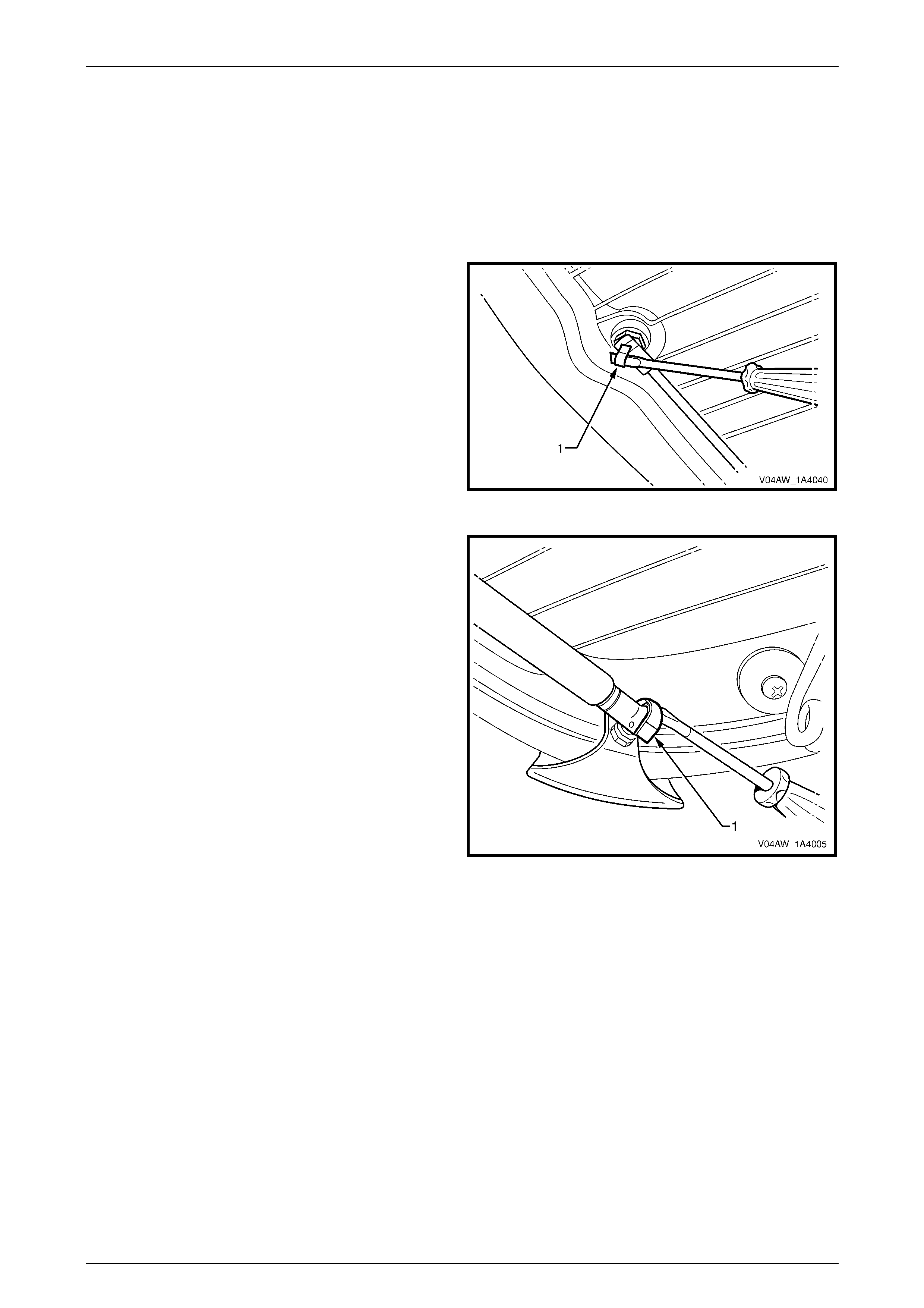
5 Using a fine flat-bladed screwdriver, unclip the
retainer (1) from the window end of the liftgate window
strut. Disconnect the window end of the liftgate
window strut from the liftgate window strut ball stud.
Repeat for the opposite side.
Figure 1A4 – 27
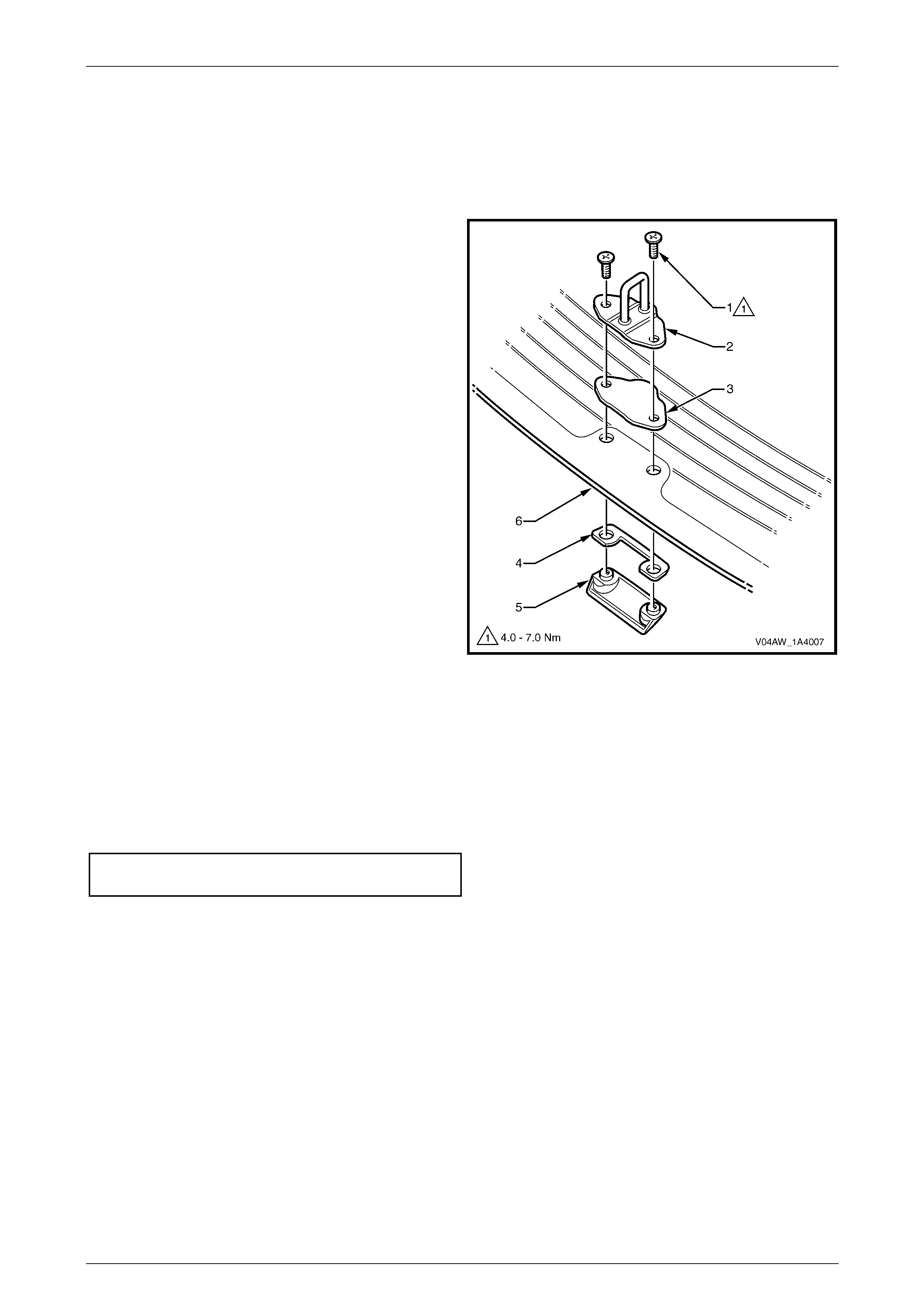
6 To remove the liftgate window assembly by removing
the liftgate window assembly from the liftgate hinge:
a Remove the screw (1), washer (2) and seal (3)
attaching the liftgate window assembly to the
liftgate window hinge from both sides of the
vehicle.
b Remove the liftgate window assembly.
7 To remove the liftgate window assembly by removing
the liftgate hinge from the body:
a Remove the nut from both of the liftgate window
hinges, refer to 2.8 Liftgate Window Hinge.
b Remove the liftgate window assembly.
Figure 1A4 – 28
Hood, Rear Com part ment Lid, Liftgate and Endgate Page 1A4–20
Page 1A4–20
Disassemble
Liftgate Window Striker and Handle
Remove
1 Remove the screws (1), in two places, from the liftgate
window striker (2).
2 Remove the liftgate window striker, liftgate window
striker seal (3), liftgate handle seal (4) and liftgate
window handle (5) from the liftgate window
assembly (6).
Figure 1A4 – 29
Reinstall
Reinstallation of the liftgate window striker and handle is the reverse of the removal procedure, noting the following:
1 Inspect the seals for damage and replace if necessary.
2 Apply thread adhesive Loctite 242 or Loctite 243 to the screw threads.
3 Tighten the screws to the correct torque specification.
Liftgate window striker and handle
screw torque specification..........................4.0 – 7.0 Nm
Hood, Rear Com part ment Lid, Liftgate and Endgate Page 1A4–21
Page 1A4–21
Liftgate Window Strut Ball Stud
Remove
1 Using a spanner, remove the liftgate wi ndow strut ball
stud (1), seals (2) and (3) and the outer retainer (4)
from the liftgate window assembly (5).
NOTE
If required, hold the outer retainer to prevent it
rotating.
2 Repeat for the opposite side.
Figure 1A4 – 30
Reinstall
Reinstallation of the liftgate window strut ball stud is the reverse of the removal procedure, noting the following:
1 Apply thread adhesive Loctite 242 or Loctite 243 to the screw threads.
2 Tighten the liftgate wi ndow strut ball stud to the correct torque specification.
Liftgate window strut ball stud
torque specification....................................4.0 – 7.0 Nm
Reinstall
Reinstallation of the liftgate window assembly is the reverse of the removal procedure, noting the following:
1 Inspect the seals for damage and replace if necessary.
2 Check that the seals on the window hinges are installed.
3 Apply thread adhesive Loctite 242 or Loctite 243 to the screw threads.
4 Tighten the screws to the correct torque specification.
Liftgate window hinge screw
torque specification....................................4.0 – 7.0 Nm
5 If required, test the operation and alignment of the rear window washer nozzle, refer to Section 1A4, 4.11 Rear
Window Washer Nozzle and Hose Assemblies in the MY 2003 VY and V2 Series Service Information.
Hood, Rear Com part ment Lid, Liftgate and Endgate Page 1A4–22
Page 1A4–22
2.8 Liftgate Window Hinge
LT Section – XX-XXX
Remove
1 Remove liftgate wi ndow upper garnish, refer to 2.3 Liftgate Window Upper Garnish.
2 If required, remove the liftgate window assembly, refer to 2.7 Liftgate Window Assembly.
3 Using a tube socket, remove the nut (1) attaching the
liftgate window hinge to the liftgate assembly.
Figure 1A4 – 31
4 Remove the liftgate window hinge and seal (1).
5 Repeat for the opposite hinge as required.
Figure 1A4 – 32
Reinstall
Reinstallation of the liftgate window hinge is the reverse of the removal procedure, noting the following:
1 Inspect the seal for damage and replace if necessary.
2 Tighten the nut to the correct torque specification.
Liftgate window hinge nut
torque specification....................................3.0 – 6.0 Nm
Hood, Rear Com part ment Lid, Liftgate and Endgate Page 1A4–23
Page 1A4–23
2.9 Liftgate Window Strut
LT Section – XX-XXX
Remove
1 Open the liftgate window assembly to relieve the tension in the liftgate window strut.
2 Using a fine flat-bladed screwdriver, unclip the
retainer (1) from the lower end of the liftgate window
strut.
3 Disconnect the lower end of the liftgate window strut
from the liftgate window assembly.
Figure 1A4 – 33
5 Using a fine flat-bladed screwdriver, unclip the
retainer (1) from the upper end of the liftgate window
strut.
6 Remove the liftgate window strut from the liftgate
assembly.
Figure 1A4 – 34
Reinstall
Reinstallation of the liftgate window strut is the reverse of the removal procedure, noting the following:
1 If required, apply a small amount of lithium based grease to the inside of the liftgate window strut ball cap.
2 Install the liftgate window strut with the cylinder end attached to the liftgate assembly.
Hood, Rear Com part ment Lid, Liftgate and Endgate Page 1A4–24
Page 1A4–24
2.10 Liftgate Window Upper Strut Bracket
LT Section – XX-XXX
Remove
1 If required, remove the liftgate window upper garnish, refer to 2.3 Liftgate Window Upper Garnish.
2 If required, disconnect the liftgate window strut from the liftgate window upper strut bracket, refer to
2.9 Liftgate Window Strut.
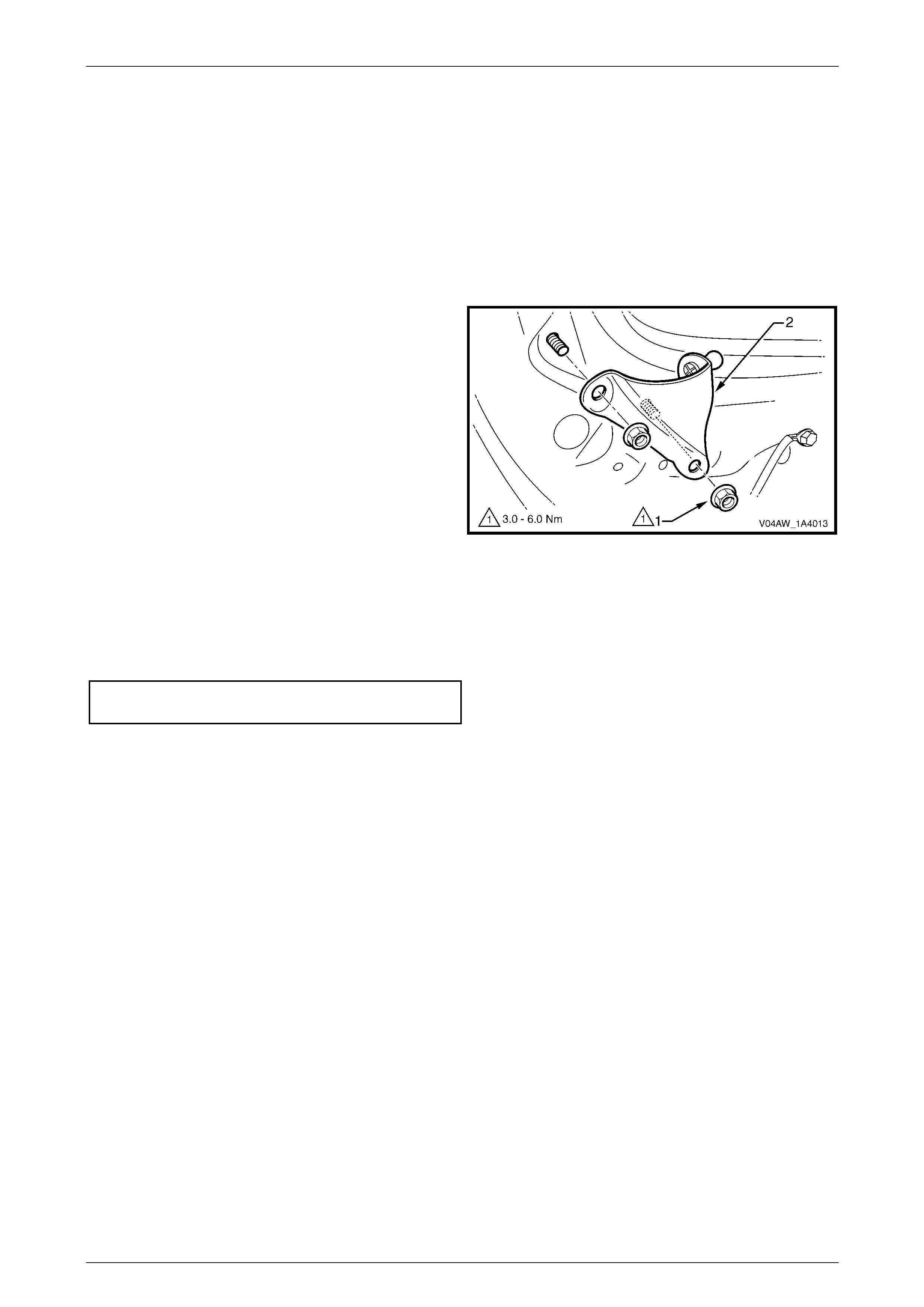
3 Remove the nut (1), in two places, attaching the
liftgate window upper strut bracket (2).
4 Remove the liftgate window upper strut bracket.
Figure 1A4 – 35
Reinstall
Reinstallation of the liftgate window upper strut bracket is the reverse of the removal procedure, noting the following:
1 Tighten the nuts to the correct torque specification.
Liftgate window upper strut bracket nut
torque specification....................................3.0 – 6.0 Nm
Hood, Rear Com part ment Lid, Liftgate and Endgate Page 1A4–25
Page 1A4–25
2.11 Liftgate Window Weatherstrip
LT Section – 11-600
Remove
1 If required, remove liftgate window lower garnish, refer to 2.1 Liftgate Window Lower Garnish.
2 If required, remove liftgate window upper garnish, refer to 2.3 Liftgate Wi ndow Upper Garnish.
3 If required, disconnect the liftgate window strut from the liftgate window assembly, refer to
2.9 Liftgate Window Strut.
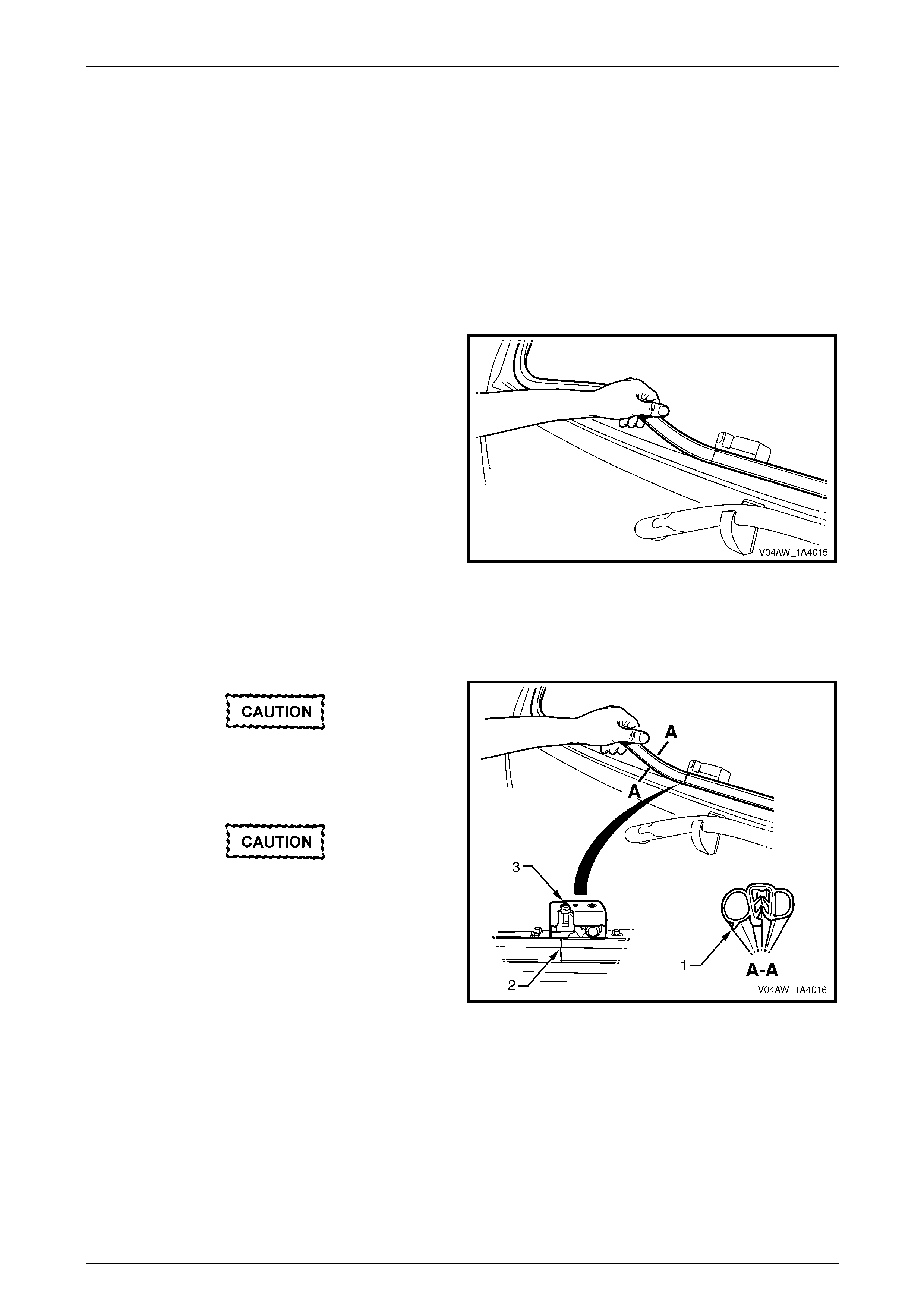
4 Remove the liftgate window weatherstrip from the
liftgate assembly opening.
Figure 1A4 – 36
Reinstall
Reinstallation of the liftgate window weatherstrip is the reverse of the removal procedure, noting the following:
Ensure that the lip of the liftgate window
weatherstrip (1) is facing tow ards the outside
of the vehicle.
Ensure that the liftgate window weatherstrip
joint (2) is aligned with the latch opening on
the liftgate window latch assembly (3).
1 If required, crimp the weatherstrip to ensure that there
is a tight fit onto the flange.
2 Install the liftgate window weatherstrip into the liftgate
assembly opening.
3 Ensure that the liftgate window weatherstrip is
correctly seated into all parts of the liftgate assembly,
taking particular attention to the corners.
Figure 1A4 – 37
Hood, Rear Com part ment Lid, Liftgate and Endgate Page 1A4–26
Page 1A4–26
2.12 Liftgate Assembly
LT Section No. – 12-500
Remove
1 Partially remove the right-hand quarter inner trim upper, refer to Section 1A8, 3.8 Quarter Inner Trim Upper.
2 Partially remove the right-hand body rear corner garnish, refer to Section 1A8, 3.9 Body Rear Corner Garnish.
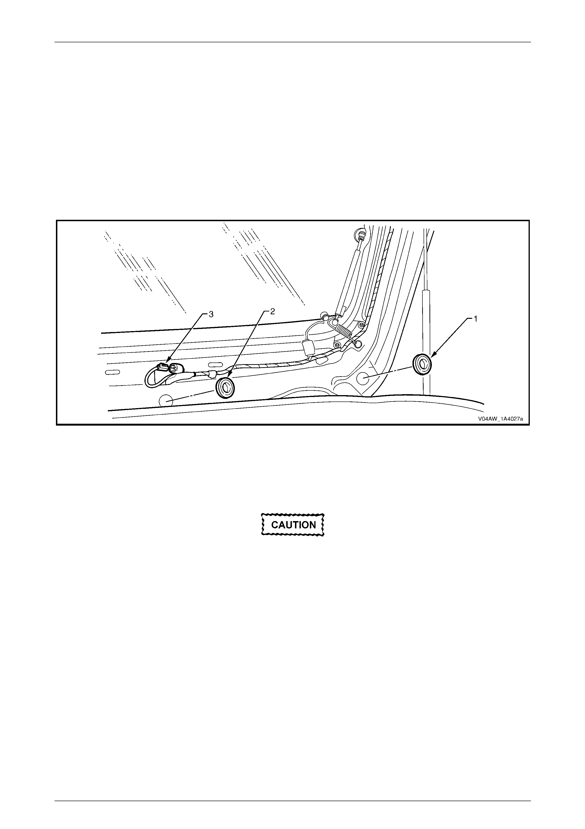
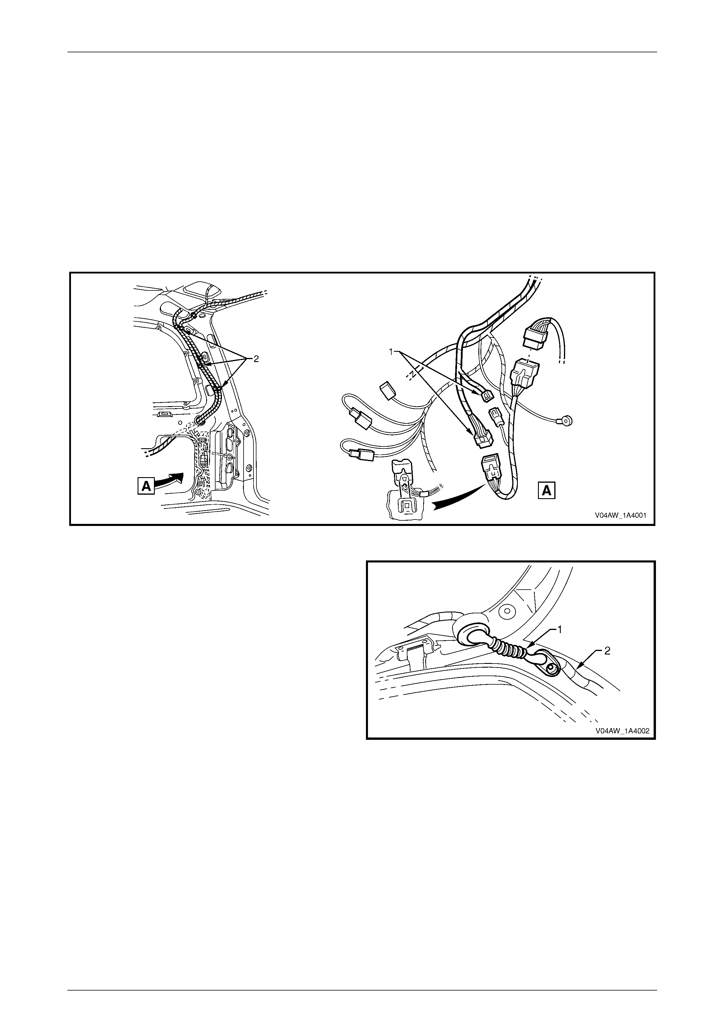
3 Disconnect the two liftgate assembly wiring harness connectors (1), refer to Figure 1A4 – 38.
4 Unclip the liftgate harness (2), in three places.
Figure 1A4 – 38
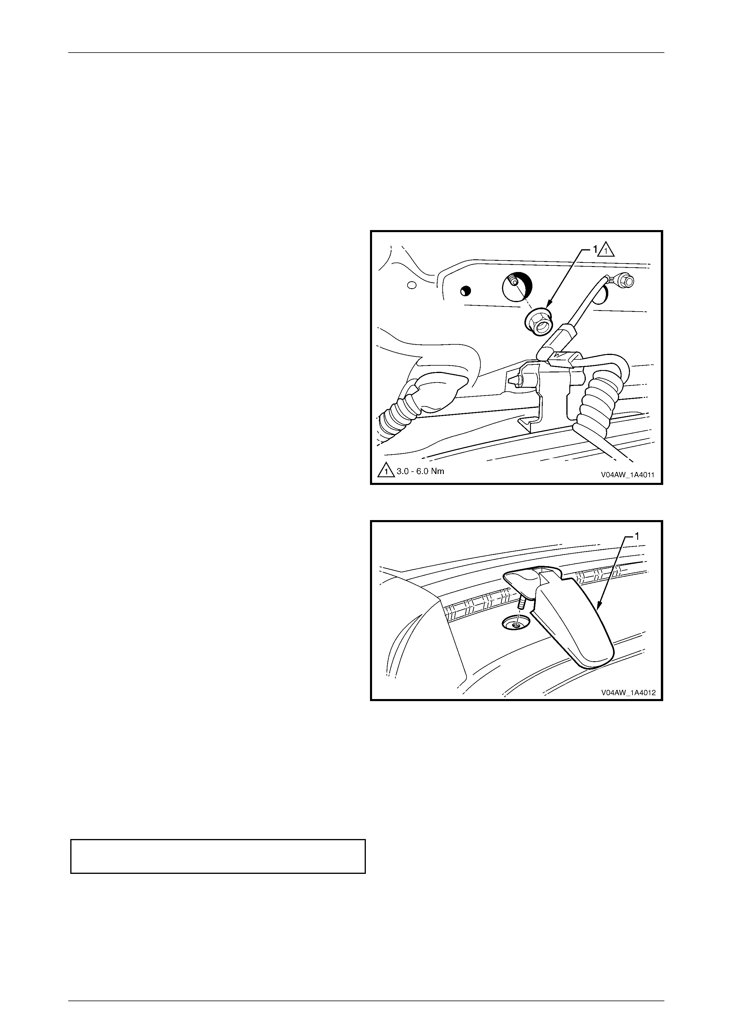
5 Remove the right-hand grommet (1) and withdraw the
liftgate harness (2) from the pillar cavity.
6 If a sunroof is fitted, disconnect the sunroof drain
tube, refer to Section 1F2 Sunroof – Online.
7 Remove the rear window washer nozzl e and hose
assemblies, refer to Section 1A4, 4.11 Rear Window
Washer Nozzle and Hose Assemblies in the MY 2003
VY and V2 Series Service Information.
8 Remove the liftgate strut assembly from the liftgate
assembly, refer to Section 1A4, 4.13 Liftgate Strut
Assembly in the MY 2003 VY and V2 Series Service
Information.
Figure 1A4 – 39
Hood, Rear Com part ment Lid, Liftgate and Endgate Page 1A4–27
Page 1A4–27
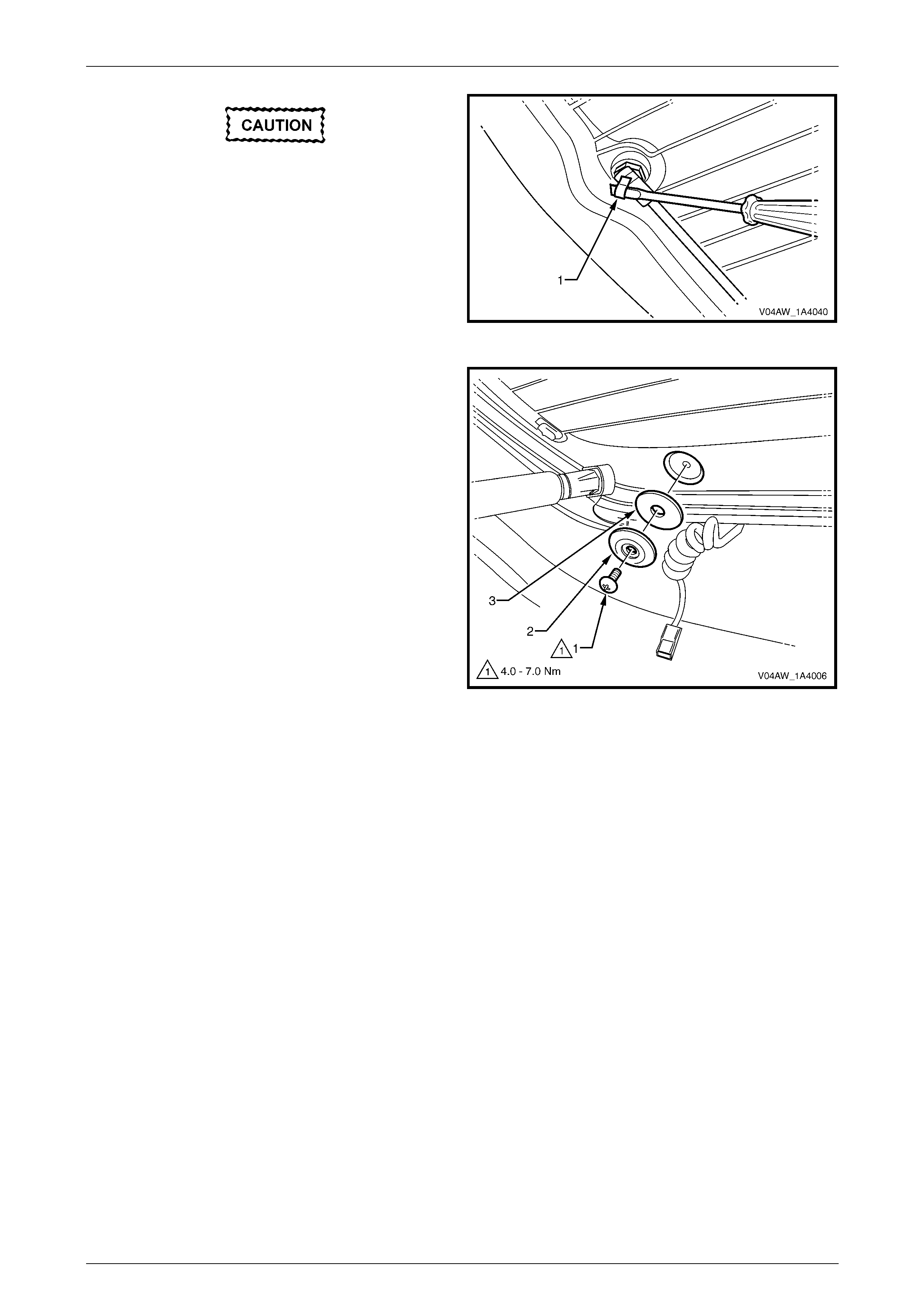
9 To remove the liftgate assembly by removing the
liftgate hinge pins:
a Remove the liftgate hinge pin retainer (1) from
the two hinge pins.
b Have an assistant support the liftgate assembly
and withdraw liftgate hinge pin (2), from either
hinge.
c Remove the liftgate assembly.
Figure 1A4 – 40
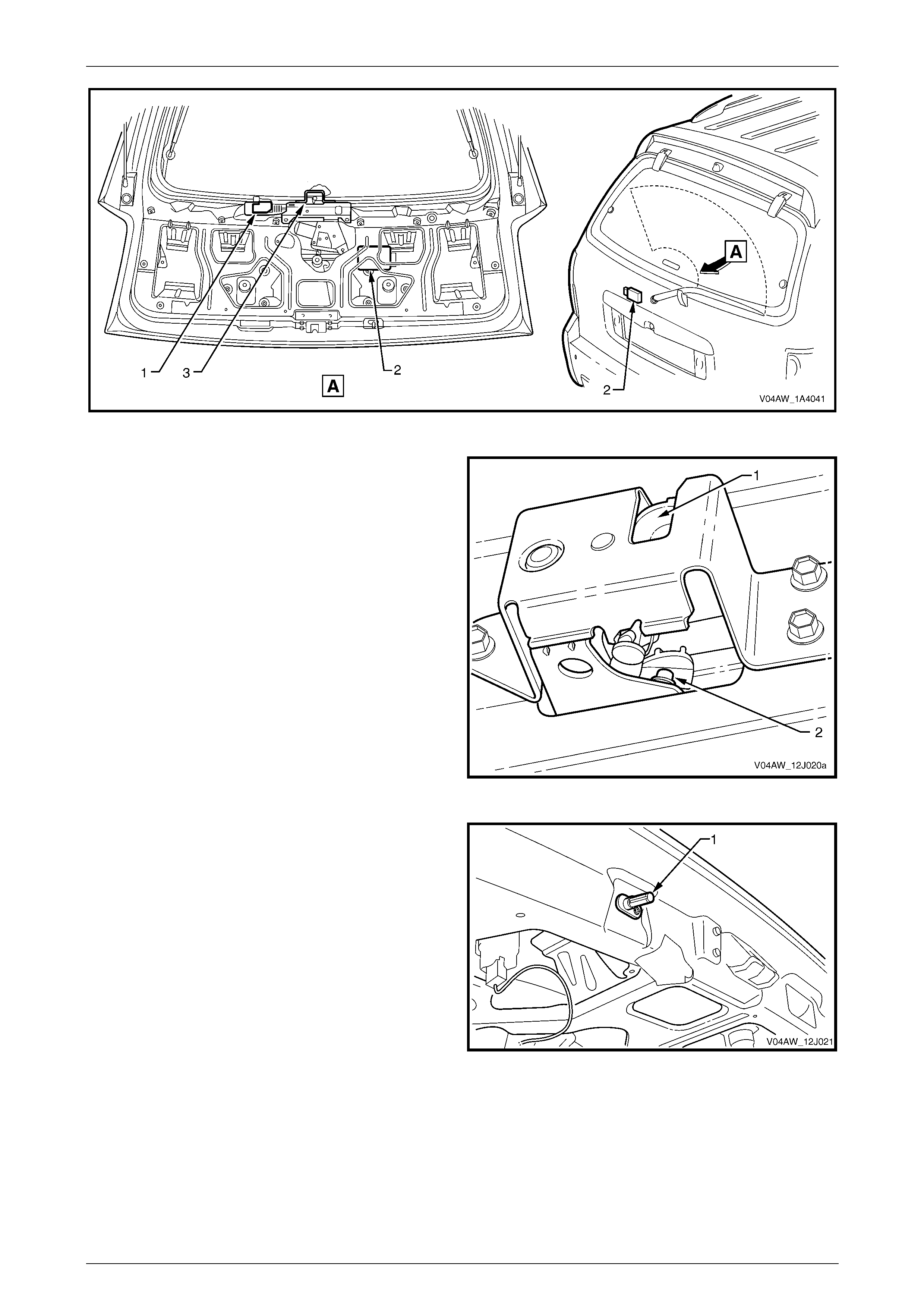
10 To remove the liftgate assembly by removing the
liftgate hinge screws:
NOTE
The alignment of the liftgate assembly will be
affected if this method to remove the liftgate
assembly is used.
a Mark the position of the hinge.
b Remove the rear wi ndow upper garnish, refer to
Section 1A8 Headlining and Interior Trim.
c Have an assistant support the liftgate assembly,
and on both sides of the liftgate assembly
remove the screws (1), in two places, plate (2)
and seal (3).
d Remove the liftgate assembly.
Figure 1A4 – 41
Disassemble
1 Remove the liftgate wi ndow lower garnish, refer to 2.1 Liftgate Window Lower Garnish.
2 Remove the liftgate lowe r trim panel, refer to 2.2 Liftgate Lower Trim Panel.
3 Remove the liftgate window upper garnish, refer to 2.3 Liftgate Window Upper Garnish.
4 Remove the liftgate inside handle, refer to Section 1A4, 4.3 Liftgate Inside Handle in the MY 2003 VY and V2
Series Service Information.
5 Remove the liftgate window release assembly, refer to 2.4 Liftgate Window Release Assembly.
6 Remove the rear wiper arm assembly, rear wiper motor assembly, rear wiper ramp and rear wiper control module,
refer to Section 12N Wipers, Washers and Horn.
7 Remove the liftgate applique assembly, refer to 2.5 Liftgate Applique Assembly.
8 Remove the liftgate applique push-button assembly, refer to Section 1A4, 4.6 Liftgate Handle Push Button
Assembly in the MY 2003 VY and V2 Series Service Information.
9 Remove the liftgate air deflector assembly, refer to 2.6 Liftgate Air Deflector Assembly.
10 Remove the liftgate window assembly, refer to 2.7 Liftgate Window Assembly.
11 Remove the liftgate window hinge, refer to 2.8 Liftgate Window Hinge.
Hood, Rear Com part ment Lid, Liftgate and Endgate Page 1A4–28
Page 1A4–28
12 Remove the liftgate wi ndow strut, refer to 2.9 Liftgate Window Strut.
13 Remove the liftgate wi ndow upper strut bracket, refer to 2.10 Liftgate Window Upper Strut Bracket.
14 Remove the liftgate wi ndow weatherstrip, refer to 2.11 Liftgate Window Weatherstrip.
15 Remove the liftgate latch assembly, refer to Section 1A4, 4.7 Liftgate Latch Assembly in the MY 2003 VY and V2
Series Service Information.
16 Remove the liftgate actuator assembly, refer to Section 1A4, 4.8 Liftgate Actuator Assembly in the MY 2003 VY
and V2 Series Service Information.
17 Remove the badges and emblems, refer to Section 1A9 Exterior Ornamentation.
Reassemble
Reassembly of the liftgate assembly is the reverse of the disassembly procedure.
Reinstall
Reinstallation of the liftgate assembly is the reverse of the removal procedure, noting the following:
1 If the liftgate assembly was removed from the liftgate hinge pin, lubricate the pin with lithium based grease prior to
installation.
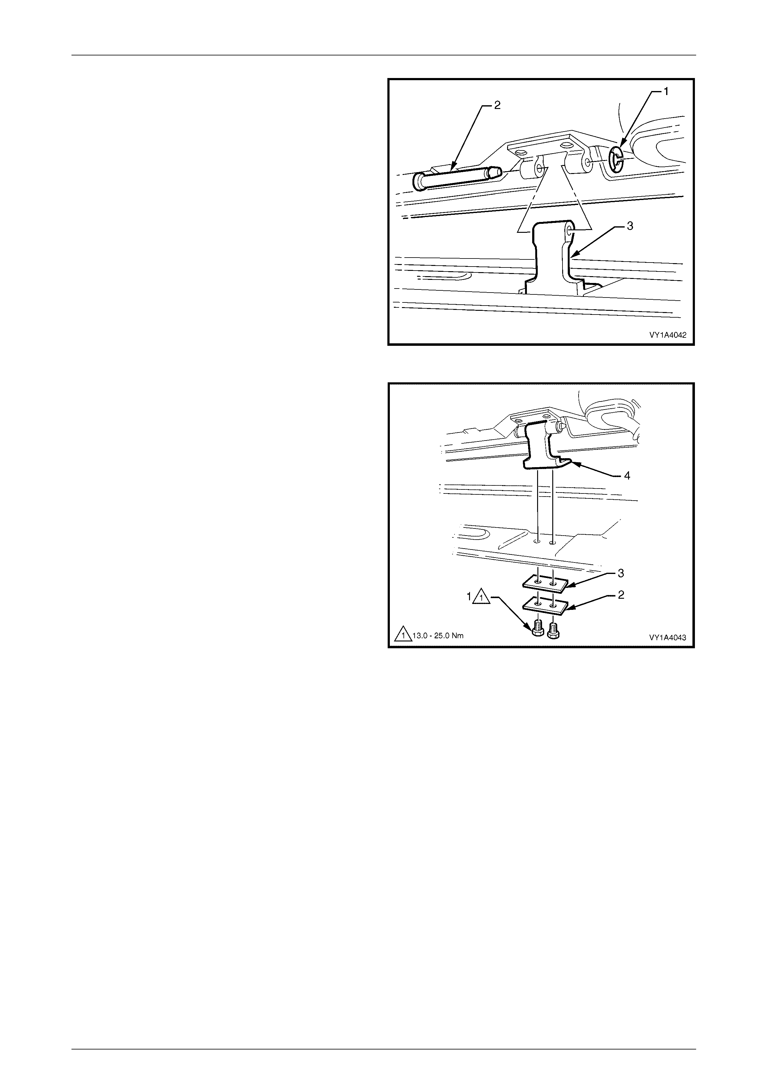
2 If the liftgate assembly was removed by removing the
liftgate hinge screws:
a Apply a small amount of non-hardening sealer to
the area shown (1).
b Set the two bumpers to the full-in position then
adjust them to achieve the required alignment of
the liftgate, refer to the following adjustment
procedure.
Figure 1A4 – 42
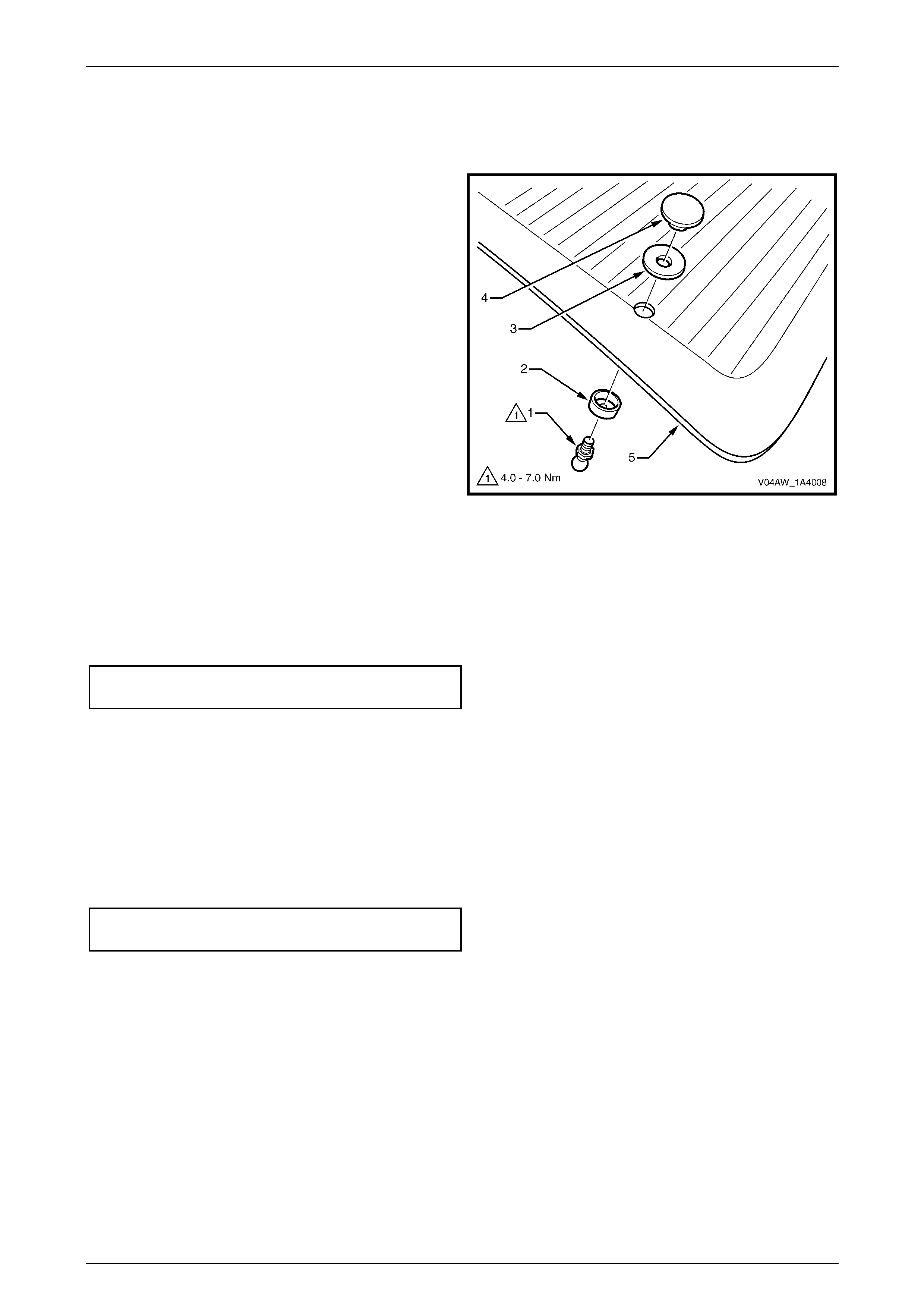
For a vehicle equipped with a sunroof, the
rear drain tube plug must be removed from
the grommet (1) for drainage of the sunroof.
Ensure that the drain tube is fitted, refer to
Section 1F2 Sunroof – Online.
Ensure that the drain tube plug (2) is
installed if a sunroof is not fitted to the
vehicle.
3 If a sunroof is fitted, connect the drain tube.
Figure 1A4 – 43

Hood, Rear Com part ment Lid, Liftgate and Endgate Page 1A4–29
Page 1A4–29
4 Before installing the trim panels, test the operation of the following items:
• Rear wiper
• Rear window washer
• High mount stop lamp
• Rear compartment courtesy lamp switch
• Liftgate window release actuator
• Liftgate lock mechanism.
5 Tighten the screws to the correct torque specification.
Liftgate hinge attaching screw
torque specification................................13.0 – 25.0 Nm
6 If required, test the operation and alignment of the rear window washer nozzle, refer to Section 1A4, 4.11 Rear
Window Washer Nozzle and Hose Assemblies in the MY 2003 VY and V2 Series Service Information.
Adjust
Correct alignment of the liftgate assembly is critical to its operation and to the aesthetics of the vehicle. The following
components allow adjustment of the liftgate assembly:
• Liftgate bumpers: Provide adjustment at the outer area of the liftgate assembly.
• Liftgate hinge (body side) screws: Provide forward, rearward and skew adjustment of the liftgate assembly.
• Liftgate striker assembly: Provides vertical and sideways adjustment of the liftgate assembly.
Whenever alignment is required, perform adjustment in the following order:
1 If fitted, remove the liftgate striker assembly, refer to Section 1A4, 4.15 Liftgate Striker Assembly in the MY 2003
VY and V2 Series Service Information.
2 Ensure that the liftgate weatherstrip assembly is installed and the liftgate bumpers are fitted and set fully in, refer
to Section 1A4, 4.14 Liftgate Assembly in the MY 2003 VY and V2 Series Service Information.
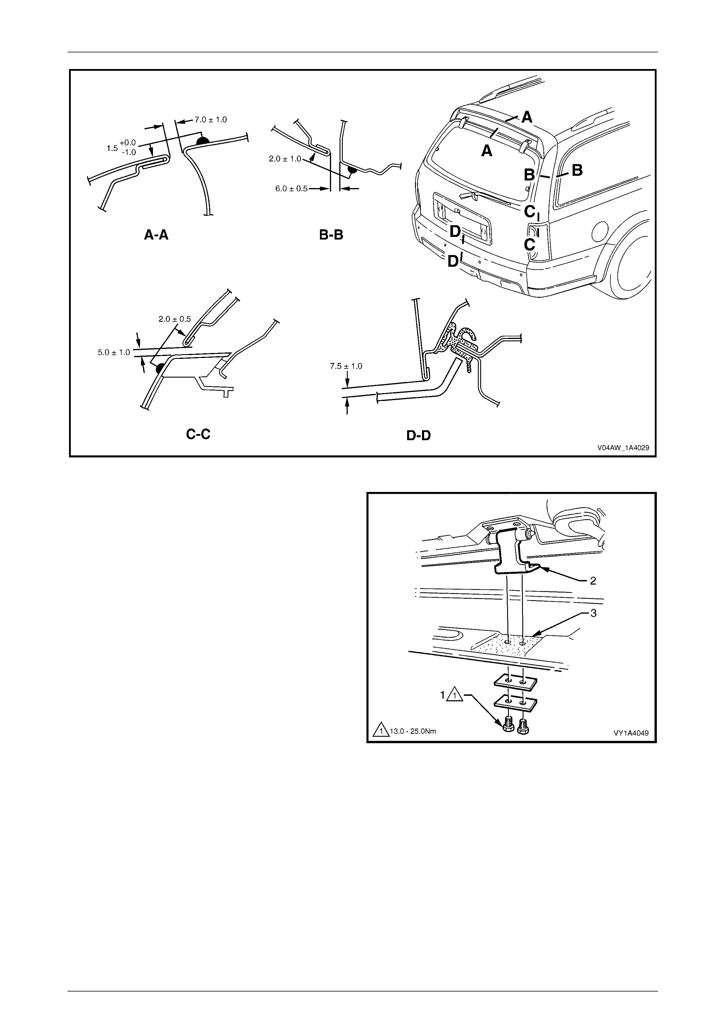
3 Carefully close the liftgate assembly while watching so that the top and each side do not contact the vehicle.
4 Referring to Figure 1A4 – 44, check the alignment of the liftgate assembly for width and consistency of gap to the
roof panel, quarter panel each side, tail lamps and rear bumper fascia.
Hood, Rear Com part ment Lid, Liftgate and Endgate Page 1A4–30
Page 1A4–30
Figure 1A4 – 44
5 If the gap between the liftgate assembly and the roof
panel is not within specification and/or is not parallel
to the quarter panel on each side, then open the
liftgate assembly and adjust the position of the liftgate
hinges.
a If required, remove the rear window upper
garnish, refer to Section 1A8 Headlining and
Interior Trim.
b Loosen the screws (1), in two places, attaching
the liftgate hinge (2).
c If required, lift the liftgate hinge away from the
body and apply a small amount of non-
hardening sealer to the area shown (3).
d Adjust the position of the liftgate hinge, tighten
the screws and recheck the liftgate assembly
alignment.
NOTE
Do not make all adjustments at once. Perform
one adjustment, carefully close the liftgate
assembly, check its position and make further
adjustments until correct alignment is achieved.
Figure 1A4 – 45
6 If the gap between the liftgate assembly and the roof panel is within specification and the liftgate assembly is
parallel to the quarter panel on each side, open the liftgate assembly and adjust the liftgate bumpers to provide a
slightly greater gap at the lower edge of the liftgate assembly above each tail lamp. This allows the liftgate striker
assembly to pull the liftgate assembly in slightly when closed.
7 Install the liftgate striker assembly, refer to refer to Section 1A4, 4.15 Liftgate Striker Assembly in the MY 2003 VY
and V2 Series Service Information.
8 Close the liftgate assembly and watch so that the liftgate striker assembly does not pull the liftgate assembly to
one side and change the panel gaps. If it does, move the liftgate striker assembly as required.

Hood, Rear Com part ment Lid, Liftgate and Endgate Page 1A4–31
Page 1A4–31
9 Tighten the screws to the correct torque specification.
Liftgate hinge attaching screw
torque specification................................13.0 – 25.0 Nm

Hood, Rear Com part ment Lid, Liftgate and Endgate Page 1A4–32
Page 1A4–32
3 Torque Wrench Specifications
High Mount Stop Lamp Assembly Attaching Screw ......................1.0 – 3.0 Nm
Liftgate Air Deflector Assembly Attaching Nut...............................2.0 – 5.0 Nm
Liftgate Air Deflector Assembly Attaching Screw...........................2.0 – 5.0 Nm
Liftgate Applique Assembly Attaching Nut.....................................2.0 – 5.0 Nm
Liftgate Hinge Attaching Screw..................................................13.0 – 25.0 Nm
Liftgate Window Hinge Nut............................................................3.0 – 6.0 Nm
Liftgate Window Hinge Screw........................................................4.0 – 7.0 Nm
Liftgate Window Latch Assembly Attaching Screw........................2.0 – 5.0 Nm
Liftgate Window Release Actuator Attaching Screw .....................2.0 – 5.0 Nm
Liftgate Window Release Assembly Attaching Screw.................6.0 – 14.0 Nm
Liftgate Window Striker and Handle Screw...................................4.0 – 7.0 Nm
Liftgate Window Strut Ball Stud.....................................................4.0 – 7.0 Nm
Liftgate Window Upper Strut Bracket Nut......................................3.0 – 6.0 Nm