
Headlining and Interior Trim Page 1A8–1
Page 1A8–1
Section 1A8
Headlining and Interior Trim
ATTENTION
Before performing any service operation or other procedure described in this Section, refer to Section 00
Warnings, Cautions and Notes for correct workshop practices with regard to safety and/or property damage.
1 General Information............................................................................................................................... 2
2 Service Operations................................................................................................................................3
2.1 Quarter Inner Trim Panel Vent...............................................................................................................................5
Remove ...................................................................................................................................................................5
Reinstall ..................................................................................................................................................................5
2.2 Rear Cup Holder.....................................................................................................................................................6
Remove ...................................................................................................................................................................6
Reinstall ..................................................................................................................................................................6
2.3 Front Cup Holder....................................................................................................................................................7
Remove ...................................................................................................................................................................7
Reinstall ..................................................................................................................................................................7
2.4 Quarter Inner Trim Stowage Door.........................................................................................................................8
Remove ...................................................................................................................................................................8
Disassemble ...........................................................................................................................................................8
Reassemble ............................................................................................................................................................8
Reinstall ..................................................................................................................................................................8
2.5 Quarter Inner Trim Speaker Grille.........................................................................................................................9
Remove ...................................................................................................................................................................9
Disassemble ...........................................................................................................................................................9
Reassemble ............................................................................................................................................................9
Reinstall ..................................................................................................................................................................9
2.6 Luggage Hook ......................................................................................................................................................10
Remove .................................................................................................................................................................10
Reinstall ................................................................................................................................................................10
2.7 Accessory Power Socket.....................................................................................................................................11
Remove .................................................................................................................................................................11
Reinstall ................................................................................................................................................................12
2.8 Quarter Inner Trim Panel Assembly ...................................................................................................................13
Remove .................................................................................................................................................................13
Disassemble .........................................................................................................................................................14
Reassemble ..........................................................................................................................................................14
Reinstall ................................................................................................................................................................14
3 Torque Wrench Specifications........................................................................................................... 15
Techline

Headlining and Interior Trim Page 1A8–2
Page 1A8–2
1 General Information
With the following exceptions, MY 2004 AWD Wagon Headlining and Interior Trim information carries over from MY 2004
VY Wagon vehicles:
• Right–hand quarter inner trim panel assemblies for low level vehicles and high level vehicles
• Left–hand quarter inner trim panel assembly for low level vehicles
• Left–hand quar ter inner trim panel as sem bly incorp orat ing a quarter inner trim speaker gril l e for high level vehic les
For Headlining and Interior Trim information not contained within this Section, refer to Section 1A8 Headlining and
Interior Trim in the MY 2004 VY and V2 Series Service Information.
Headlining and Interior Trim Page 1A8–3
Page 1A8–3
2 Service Operations
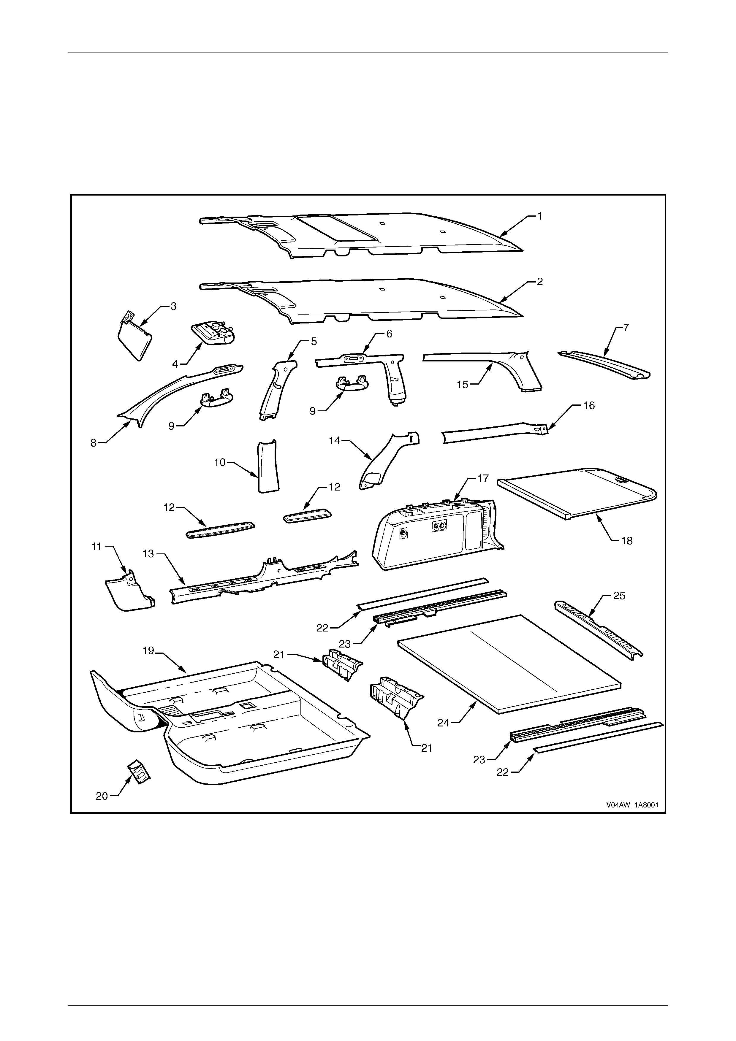
NOTE
The following chart is provided to assist with the
identification of the components.
Figure 1A8 – 1

Headlining and Interior Trim Page 1A8–4
Page 1A8–4
Legend
1 Headlining Assembly - With Sunroof
2 Headlining Ass embly - Without Sunroof
3 Sunshade Assembly
4 Roof Console
5 Centre Pillar Upper Trim
6 Body Lock Pillar Ga rn ish
7 Rear Window Upper Garnish
8 Windshield Side Garnish
9 Assist Handle
10 Centre Pillar Lower Trim
11 Hinge Pillar Trim Assembly
12 Side Sill Trim Plate
13 Side Sill Trim
14 Body Lock Pillar Lower Trim
15 Body Rear Corner Garnish
16 Quarter I nner Trim Upper
17 Quarter Inner Trim Panel Assembly
18 Luggage Shade Assembly
19 Front Floor Carpet Assembly
20 Driver Footrest
21 Rear Floor Filler Panel
22 Luggage Tie Down Rail Cover
23 Luggage Tie Down Rail
24 Rear Com partment Floor Carpet Assembly
25 Rear End Trim Panel
Headlining and Interior Trim Page 1A8–5
Page 1A8–5
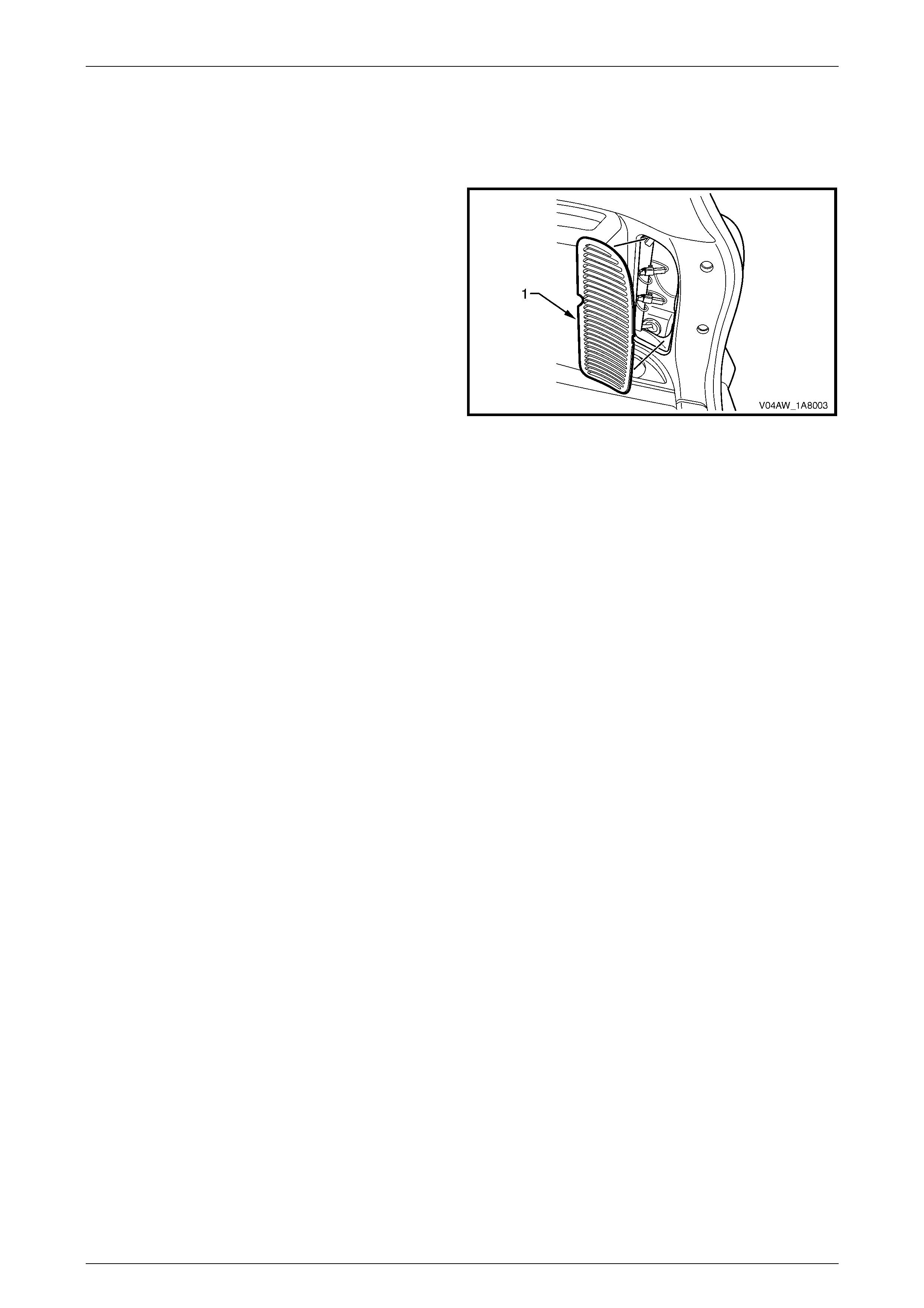
2.1 Quarter Inner Trim Panel Vent
LT Section – 14-490
Remove
1 Lever the centre of the rear edge of the quarter inner
trim panel vent (1) away from the quarter inner trim
panel assembly.
2 Remove the quarter inner trim panel vent.
Reinstall
Reinstallation of the quarter inner trim panel vent is the
reverse of the removal procedure.
Figure 1A8 – 2
Headlining and Interior Trim Page 1A8–6
Page 1A8–6
2.2 Rear Cup Holder
LT Section –
Remove
1 Lift out the rear cup holder (1).
Reinstall
Reinstall atio n of the rear cup holder is the r ev erse of the
removal procedur e.
Figure 1A8 – 3
Headlining and Interior Trim Page 1A8–7
Page 1A8–7
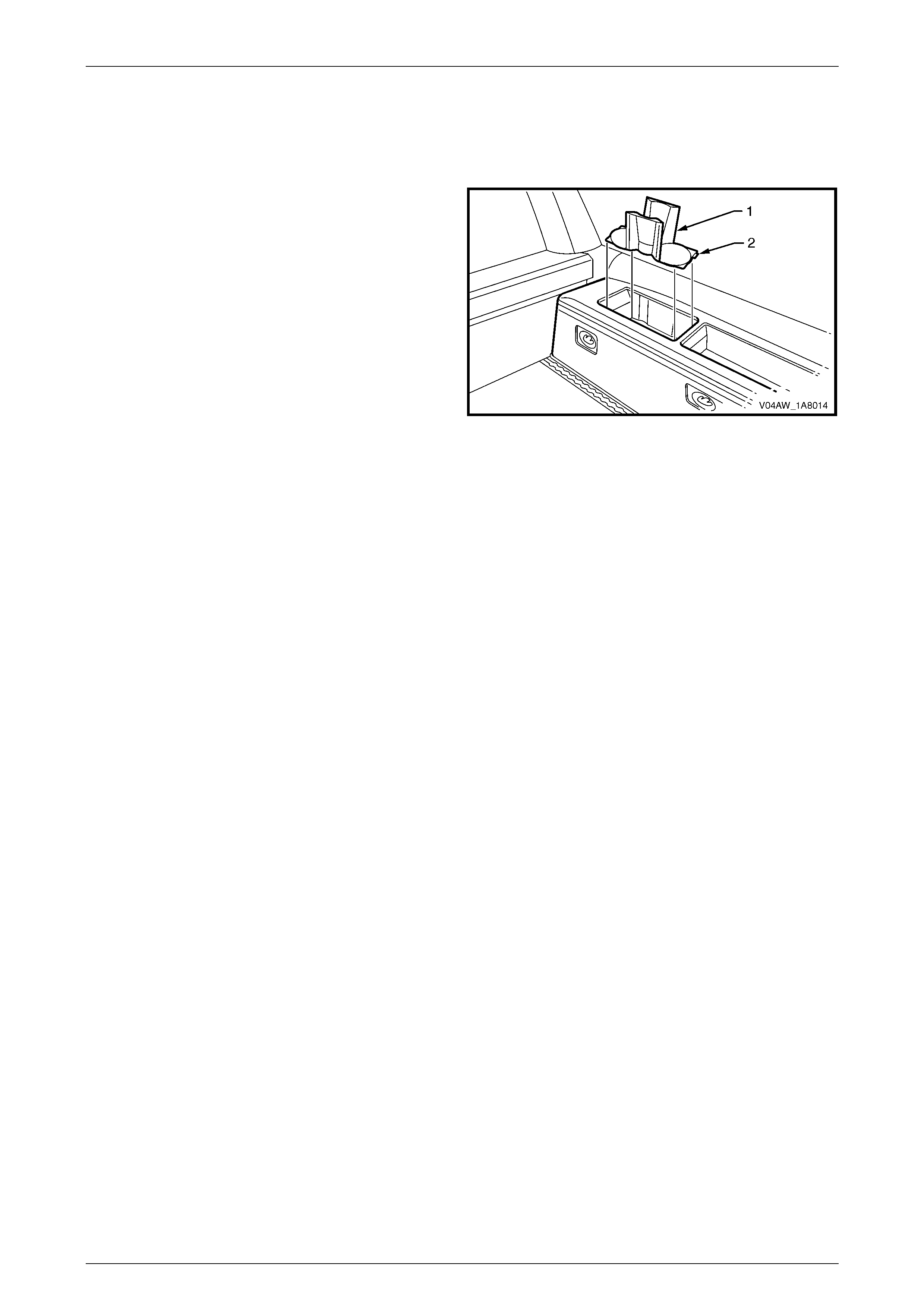
2.3 Front Cup Holder
LT Section – 14-900
Remove
1 Remove the front cup holder (1) by disengaging the
retaining lug (2) securing the front cup holder to the
quarter inner trim panel assembly.
Reinstall
Reinstallation of the front cup holder is the reverse of the
removal procedur e.
Figure 1A8 – 4
Headlining and Interior Trim Page 1A8–8
Page 1A8–8
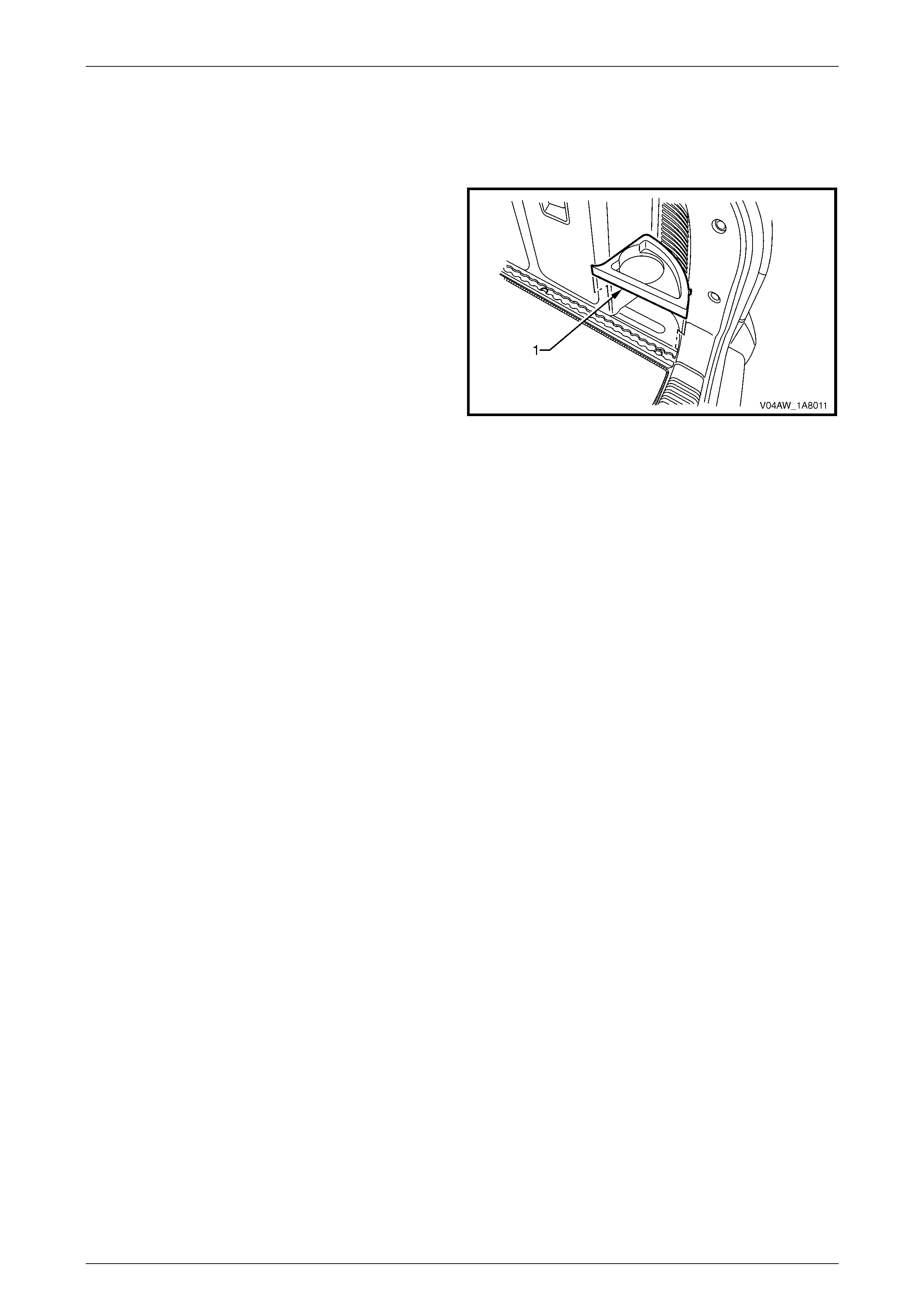
2.4 Quarter Inner Trim Stowage Door
LT Section – 14-490
NOTE
On high level vehicles, the quarter inner trim
speaker grille is installed on the left-hand side of
the vehicle instead of the quarter inner trim
stowage door.
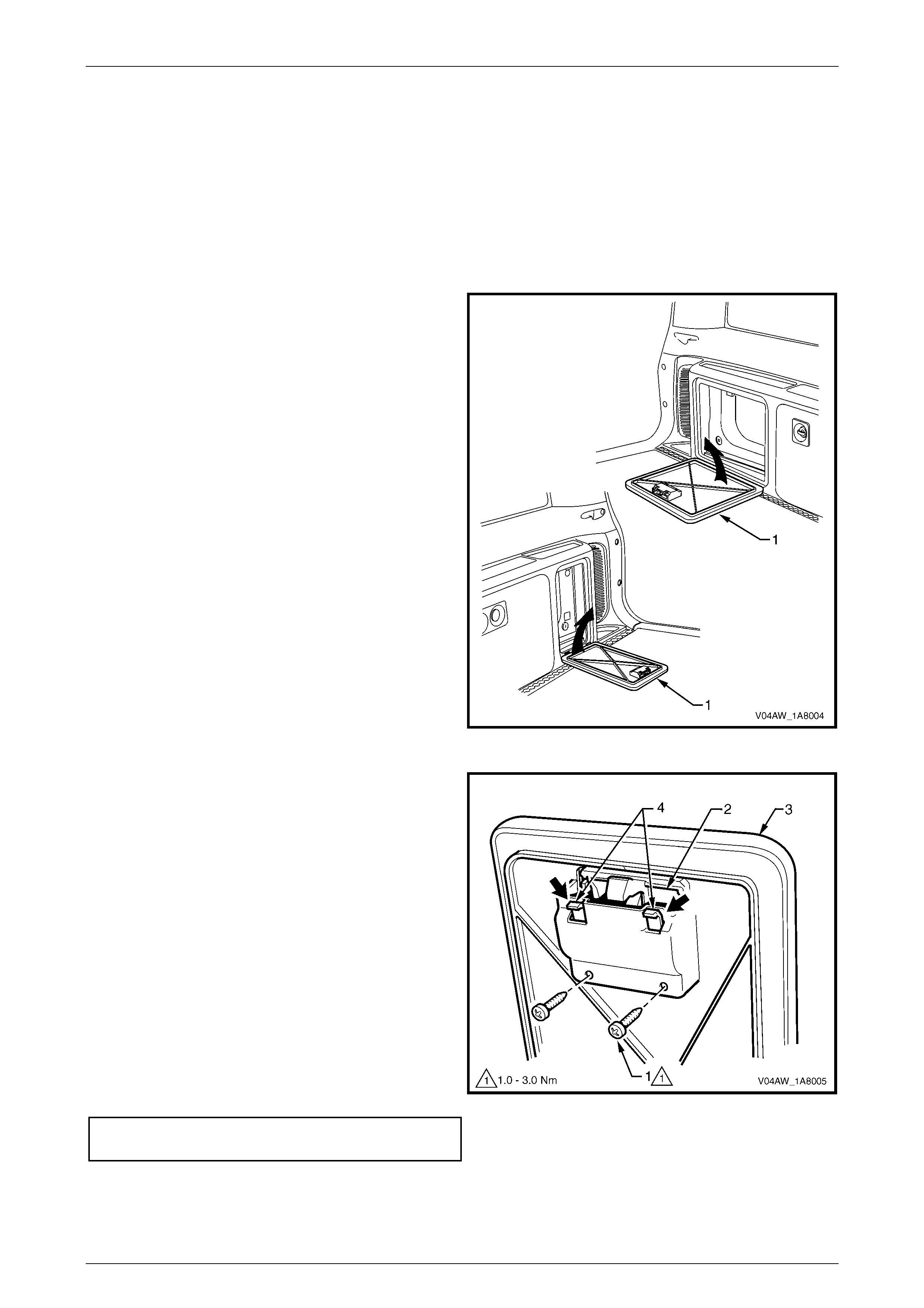
Remove
1 Open the quarter inner trim stowage door (1).
2 Lift the quarter inner trim stowage door slightly to
detach the hinge from the quarter inner trim panel
assembly.
3 Remove the quarter inner trim stowage door from the
quarter inner trim panel assembly.
Figure 1A8 – 5
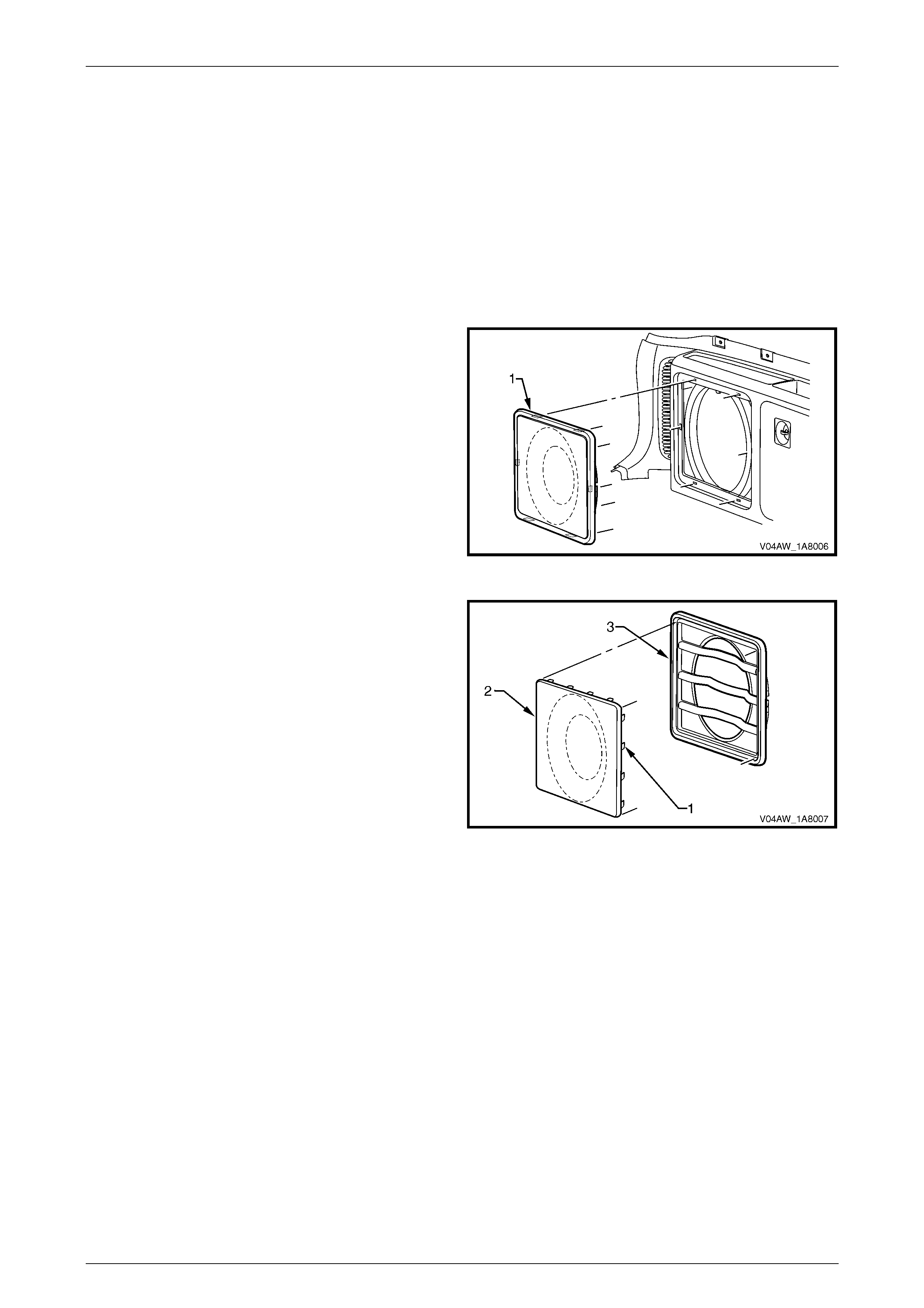
Disassemble
1 Remove the screws (1), in two places, attaching the
quarter inner trim stowage door latch assembly (2) into
the quarter inner trim stowage door (3).
2 Push down on the retaining lugs (4), in two places,
and remove the quarter inner trim stowage door
handle.
Reassemble
Reassembly of the quarter inner trim stowage door is the
reverse of the disassembly procedure, noting the following:
1 Ensure that the quarter inner trim stowage door latch
assembly is pressed firmly into the quarter inner trim
stowage door.
2 Tighten the screws to the correct torque specification.
Quarter inner trim stowage door latch
assembly screw torque specification..........1.0 – 3.0 Nm
Figure 1A8 – 6
Reinstall
Reinstallation of the quarter inner trim stowage door is the reverse of the removal procedure.
Headlining and Interior Trim Page 1A8–9
Page 1A8–9
2.5 Quarter Inner Trim Speaker Grille
LT Section –
NOTE
The quarter inner trim speaker grille is only fitted
to high level vehicles. For service operations
relating to the subwoofer speaker and subwoofer
amplifier, refer to Section 12D Entertainment
System.
Remove
1 Carefully prise the quarter inner trim speaker grille (1)
from the quarter inner trim panel assembly.
NOTE
The quarter inner trim speaker grille is attached
to the quarter inner trim panel assembly with six
clips.
Figure 1A8 – 7
Disassemble
1 Straighten the tabs (1), in sixteen places, on the
speaker grille (2) and remove the speaker grille from
the quarter inner trim speaker grille housing (3).
Reassemble
Reassembly of the quarter inner trim speaker grille is the
reverse of the disassembly procedure, noting the following:
1 Ensure that the edge of the speaker grille is sea ted in
the quarter inner trim speaker grille housing.
2 Bend the tabs to retain the speaker grille in the quarter
inner trim speaker grille housing.
Figure 1A8 – 8
Reinstall
Reinstallation of the quarter inner trim speaker grille is the reverse of the removal procedure.
Headlining and Interior Trim Page 1A8–10
Page 1A8–10
2.6 Luggage Hook
LT Section –
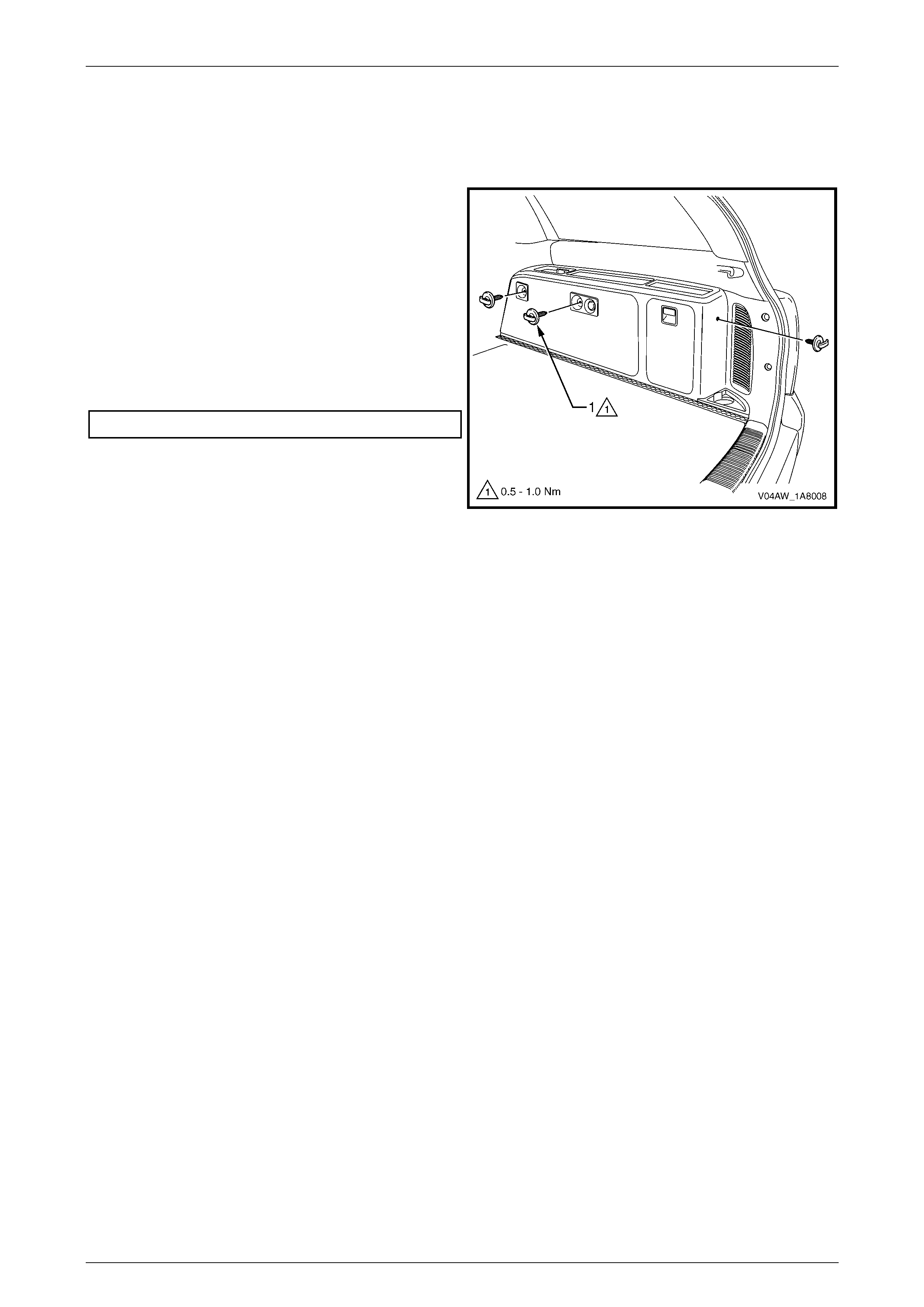
Remove
1 Unscrew the luggage hook from the quarter inner trim
panel assembly.
Reinstall
Reinstallation of the luggage hook is the reverse of the
removal procedure, noting the following:
1 Tighten the fasteners to the correct torque
specification.
Luggage hook torque specification............. 0.5 – 1.0 Nm
Figure 1A8 – 9
Headlining and Interior Trim Page 1A8–11
Page 1A8–11
2.7 Accessory Power Socket
LT Section – 14-900
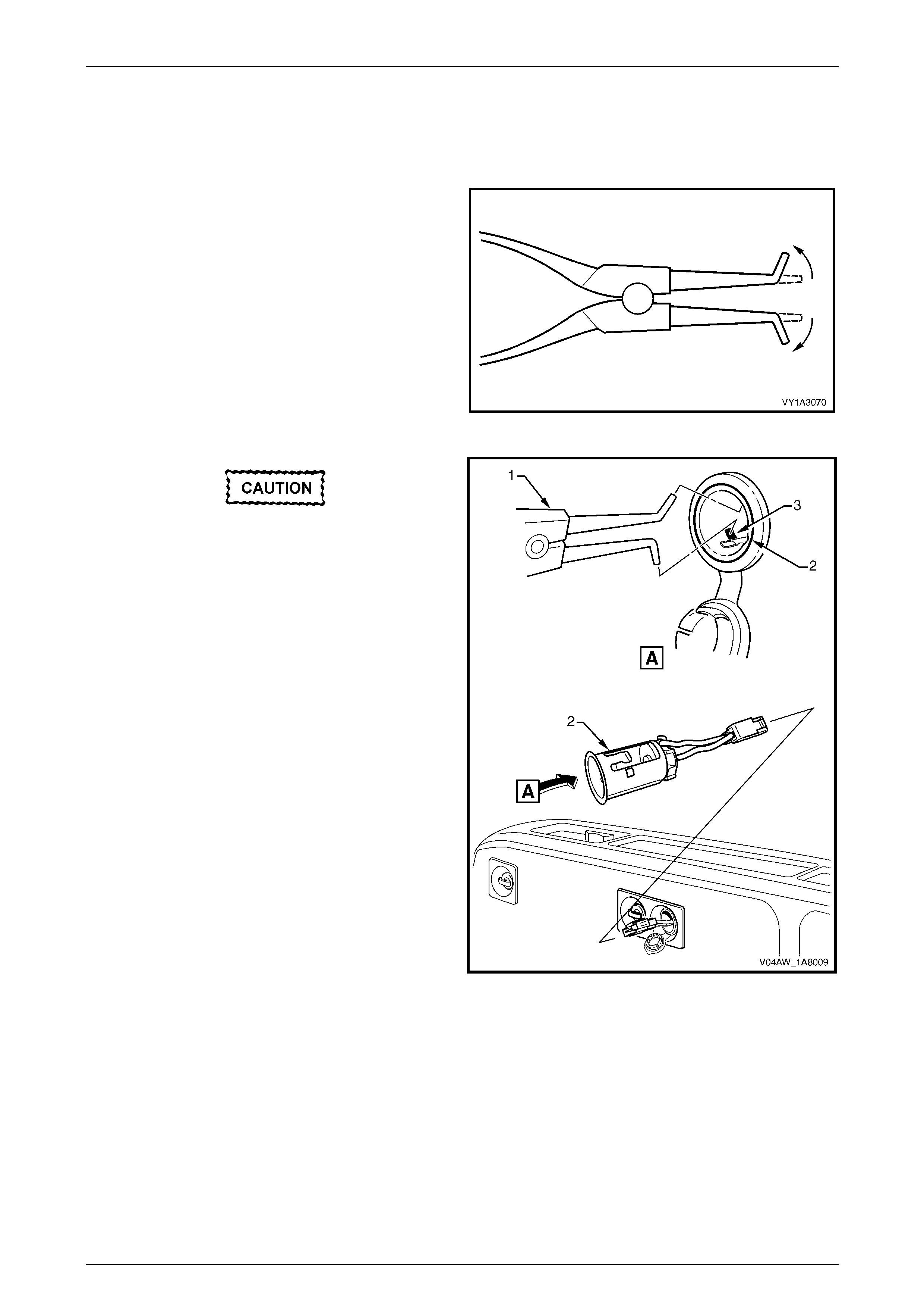
Remove
1 To remove the accessory power socket, modify a pair
of external circlip pliers by bending the tips outward to
between 60° and 90°.
Figure 1A8 – 10
The accessory power socket fitted to the
right-hand quarter inner trim panel provides
continuous 12 volt power.
2 Remove fuse F37, refer to Section 12O Fuses, Rela ys
and Wiring Harnesses.
3 Insert the modified circlip pliers (1) into the accessory
power socket (2) and locate the tips of the modified
circlip pliers onto the retaining tab (3), in two places.
4 Open the modified circlip pliers to press the tabs, and
prise the socket from the bezel using a fine, flat-blade
screwdriver.
5 Withdraw the accessory power socket, disconnect the
wiring connector and remove the accessory power
socket.
Figure 1A8 – 11
Headlining and Interior Trim Page 1A8–12
Page 1A8–12
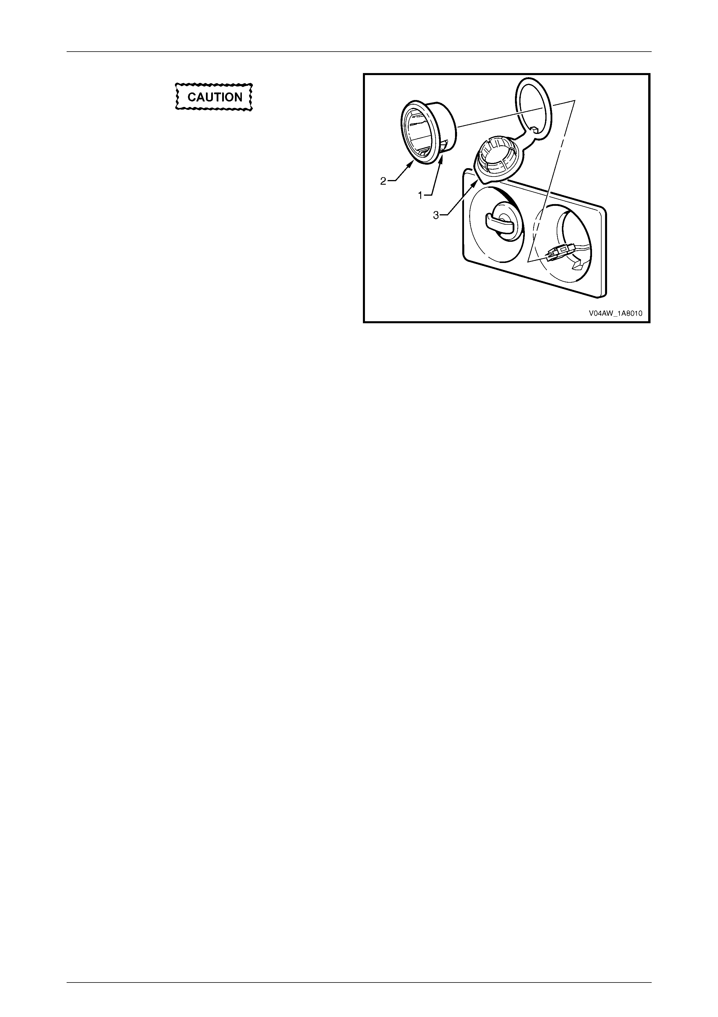
Take care as the tabs (1) can break.
6 Carefully withdraw the bezel (2) and cover (3).
NOTE
The accessory power socket must be removed
before performing this step as its removal
releases the bezel retaining tabs.
7 If required, slide the cover from the bezel.
Figure 1A8 – 12
Reinstall
Reassembly of the accessory power socket is the reverse of the disassembly procedure, noting the following:
1 The accessory power socket can only be installed in one orientation.
Headlining and Interior Trim Page 1A8–13
Page 1A8–13
2.8 Quarter Inner Trim Panel Assembly
LT Section – 14-490
Remove
1 Remove the rear seat bolster assembly, refer to Section 1A7 Seat Assemblies.
2 Fold forward the rear seat back, refer to Section 1A7 Seat Assemblies.
3 Remove the quarter inner trim upper, refer to Section 1A8 Headlining and Interior Trim in the MY 2004 VY and V2
Series Service Information.
4 Remove the rear cup holder, refer to 2.2 Rear Cup Holder.
5 Loosen the rear end trim panel, refer to Section 1A8 Headlining and Interior Trim in the MY 2004 VY and V2 Series
Service Information.
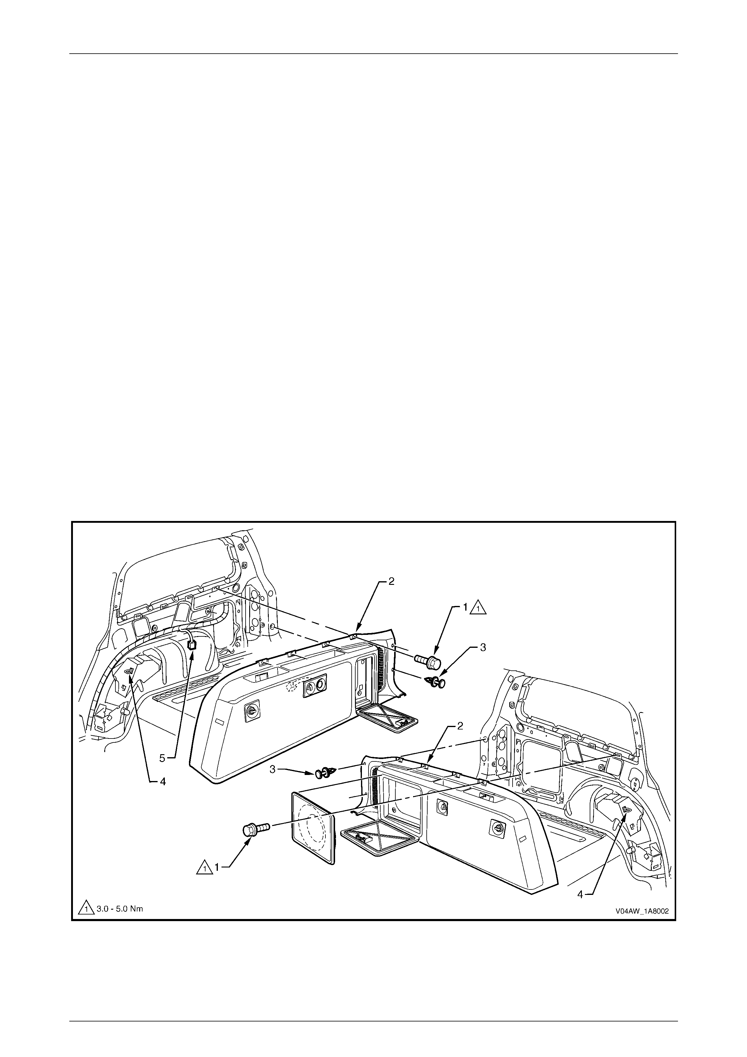
6 Remove the screws (1), in four places, along the top edge of the quarter inner trim panel assembly (2), refer to
Figure 1A8 – 13.
7 Remove the retainers (3), in two places, attaching the quarter inner trim panel assembly.
8 Remove the quarter inner trim panel assembly and lift it forward over the rear seat back striker (4).
9 If removing the right-hand quarter inner trim panel assembly, disconnect the accessory power socket connector (5).
NOTE
For service operations relating to the subwoofer
speaker and subwoofer amplifier, refer to
Section 12D Entertainment System.
Figure 1A8 – 13

Headlining and Interior Trim Page 1A8–14
Page 1A8–14
Disassemble
1 Remove the quarter inner trim panel vent, refer to 2.1 Quarter Inner Trim Panel Vent.
2 Remove the front cup holder, refer to 2.3 Front Cup Holder.
3 Remove the quarter inner trim stowage door, refer to 2.4 Quarter Inner Trim Stowage Door.
4 Remove the quarter inner trim speaker grille, refer to 2.5 Quarter Inner Trim Speaker Grille.
5 Remove the luggage hook, in three places, refer to 2.6 Luggage Hook.
6 For the right-hand quarter inner trim panel assembly, remove the accessory power socket, refer to
2.7 Accessory Power Socket.
Reassemble
Reassembly of the quarter inner trim panel assembly is the reverse of the disassembly procedure.
Reinstall
Reinstallation of the quarter inner trim panel assembly is the reverse of the removal procedure, noting the following:
1 Feed the quarter inner trim panel stowage bag into the quarter panel, so that it does not interfere with the final
fitment of the quarter inner trim panel assembly.
2 Ensure that the outer edge of the quarter inner trim panel assembly engages the rear door opening weatherstrip.
3 Tighten all fasteners to the correct torque specification.
Quarter inner trim panel assembly
attaching screw torque specification........... 3.0 – 5.0 Nm

Headlining and Interior Trim Page 1A8–15
Page 1A8–15
3 Torque Wrench Specifications
Luggage Hook ...............................................................................0.5 – 1.0 Nm
Quarter Inner Trim Panel Assembly Attaching Screw....................3.0 – 5.0 Nm
Quarter Inner Trim Stowage Door Latch Assembly Screw.............1.0 – 3.0 Nm