
Exterior Ornamentation Page 1A9–1
Page 1A9–1
Section 1A9
Exterior Ornamentation
ATTENTION
Before performing any service operation or other procedure described in this Section, refer to Section 00
Warnings, Cautions and Notes for correct workshop practices with regard to safety and/or property damage.
1 General Description............................................................................................................................... 3
1.1 Pictorial Index .........................................................................................................................................................3
Low Level................................................................................................................................................................4
High Level...............................................................................................................................................................6
2 Service Operations................................................................................................................................8
2.1 Radiator Grille Emblem..........................................................................................................................................8
Remove ...................................................................................................................................................................8
Reinstall ..................................................................................................................................................................8
2.2 Fender Name Plate.................................................................................................................................................9
Remove ...................................................................................................................................................................9
Reinstall ..................................................................................................................................................................9
2.3 Liftgate Emblem ...................................................................................................................................................10
Remove .................................................................................................................................................................10
Reinstall ................................................................................................................................................................10
2.4 Liftgate Name Plate, LH.......................................................................................................................................11
Remove .................................................................................................................................................................11
Reinstall ................................................................................................................................................................11
2.5 Liftgate Name Plate, RH.......................................................................................................................................12
Remove .................................................................................................................................................................12
Reinstall ................................................................................................................................................................12
2.6 Rear Quarter Window Applique Assembly Name Plate....................................................................................13
Remove .................................................................................................................................................................13
Reinstall ................................................................................................................................................................13
2.7 Roof Rack Carrier Assembly...............................................................................................................................14
Remove .................................................................................................................................................................14
Disassemble .........................................................................................................................................................14
Reassemble ..........................................................................................................................................................16
Reinstall ................................................................................................................................................................16
2.8 Luggage Carrier....................................................................................................................................................17
Remove .................................................................................................................................................................17
Reinstall ................................................................................................................................................................17
2.9 Door Opening Moulding.......................................................................................................................................18
Remove .................................................................................................................................................................18
Reinstall ................................................................................................................................................................18
2.10 Rear Quarter Window Applique Assembly.........................................................................................................19
Remove .................................................................................................................................................................19
Reinstall ................................................................................................................................................................19
2.11 Body Side Mouldings...........................................................................................................................................20
Remove .................................................................................................................................................................20
Reinstall ................................................................................................................................................................20
2.12 Wheelhouse Opening Flare Assembly ...............................................................................................................22
Front......................................................................................................................................................................22
Remove............................................................................................................................................................22
Reinstall............................................................................................................................................................22
Rear.......................................................................................................................................................................23
Remove............................................................................................................................................................23
Reinstall............................................................................................................................................................23
Techline

Exterior Ornamentation Page 1A9–2
Page 1A9–2
2.13 Rocker Panel Moulding Assembly......................................................................................................................24
Remove .................................................................................................................................................................24
Disassemble .........................................................................................................................................................26
Rocker Panel Moulding Front Insert.................................................................................................................26
Jacking Access Cover......................................................................................................................................27
Reinstall ................................................................................................................................................................27
3 Torque Wrench Specifications........................................................................................................... 28

Exterior Ornamentation Page 1A9–3
Page 1A9–3
1 General Description
With the following exceptions, MY 2004 VY AWD Wagon Exterior Ornamentation information carries over from MY
2003 VY and V2 Wagon vehicles. For information not contained within this Section, refer to Section 1A9 Exterior
Ornamentation in the MY 2003 VY and V2 Series Service Information.
• Radiator grille emblem
• Fender name plate
• Liftgate emblem
• Liftgate name plate, LH
• Liftgate name plate, RH
• Rear quarter window applique name plate
• Roof rack carrier assembly
• Luggage carrier
• Door opening moulding
• Rear quarter window applique assembly
• Body side mouldings
• Wheelhouse opening flare assembly
• Rocker panel moulding assembly
This Section describes the service procedures for the ornamentation components such as emblems, name plates,
mouldings, appliques and fin is hers.
Many of the components in this Section are affixed to the vehicle with double-sided tape or urethane adhesive. It is
imperative that the correct materials are used when reinstalling these parts, as specified in this Section. Use of materials
other than those specified may lead to premature failure.
The badging on the AWD Wagon differs depending on the Level of the vehicle. The liftgate name plate is CX8 for Low
Level vehicles and LX8 for High Level vehicles.
The rear quarter window applique assembly is fitted to the rear quarter window assembly, refer to Section 1A6,
Stationary Windows. It is fitted with a CrossXtrac name plate.
All AWD Wagon vehicles fitted with a sunroof are also fitted with a luggage carrier.
To aid in identification and service procedure location, refer to the pictorial index diagrams on the following pages.
1.1 Pictorial Index
The following diagrams provide a quick reference to the correct service procedures for the exterior ornamentation
components relevant to each vehicle model.
Exterior Ornamentation Page 1A9–4
Page 1A9–4
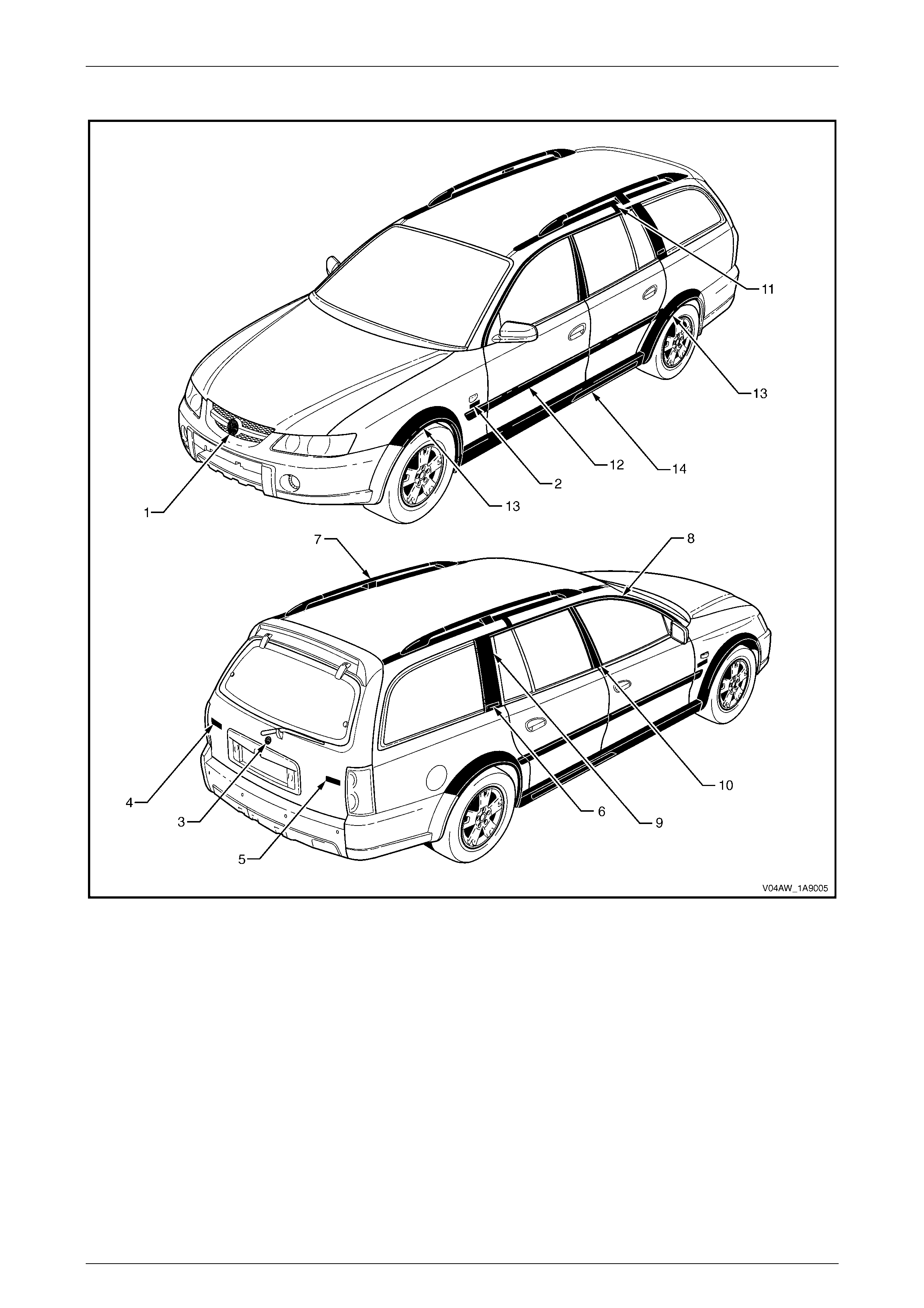
Low Level
Figure 1A9 – 1

Exterior Ornamentation Page 1A9–5
Page 1A9–5
Legend
Description
1 Radiator Grille Emblem: Lion
2 Fender Name Plate: V8
3 Liftgate Emblem: Lion Emblem
4 Lift gat e Name Plate, LH: Adventra
5 Lift gate Name Plate, RH: CX8
6 Rear Quarter Window Applique Name Plate: CrossXTrac
7 Roof Rack Carri er Ass embly
8 Door Opening Moulding
9 Rear Quarter Window Applique Assem bl y
10 Centre Pillar Upper Finisher Assembly
11 Roof Joint Finisher
12 Body Side Moulding
13 Wheelhouse Opening Flare
14 Rocker Panel Moulding Assembly
Refer To:
2.1 Radiator Grille Embl em
2.2 Fender Name Plate
2.3 Liftgate Emblem
2.4 Liftgat e Name Plate, LH
2.5 Liftgat e Name Plate, RH
2.6 Rear Quarter Window Appli que Assembly Nam e Plate
2.7 Roof Rack Carrier Ass em bl y
2.9 Door Opening Moulding
2.10 Rear Quarter Window Applique Ass em bly
Refer to Section 1A9, 3.10 Centre Pillar Upper Finisher Assembly
in the MY 2003 VY and V2 Series Service Information.
Refer to Section 1A9, 3.11 Roof Joint Finis her in the MY 2003 VY
and V2 Series Service Information.
2.11 Body Side Mouldings
2.12 Wheelhouse Opening Flare
2.13 Rocker Panel Moulding Assem bly
Exterior Ornamentation Page 1A9–6
Page 1A9–6
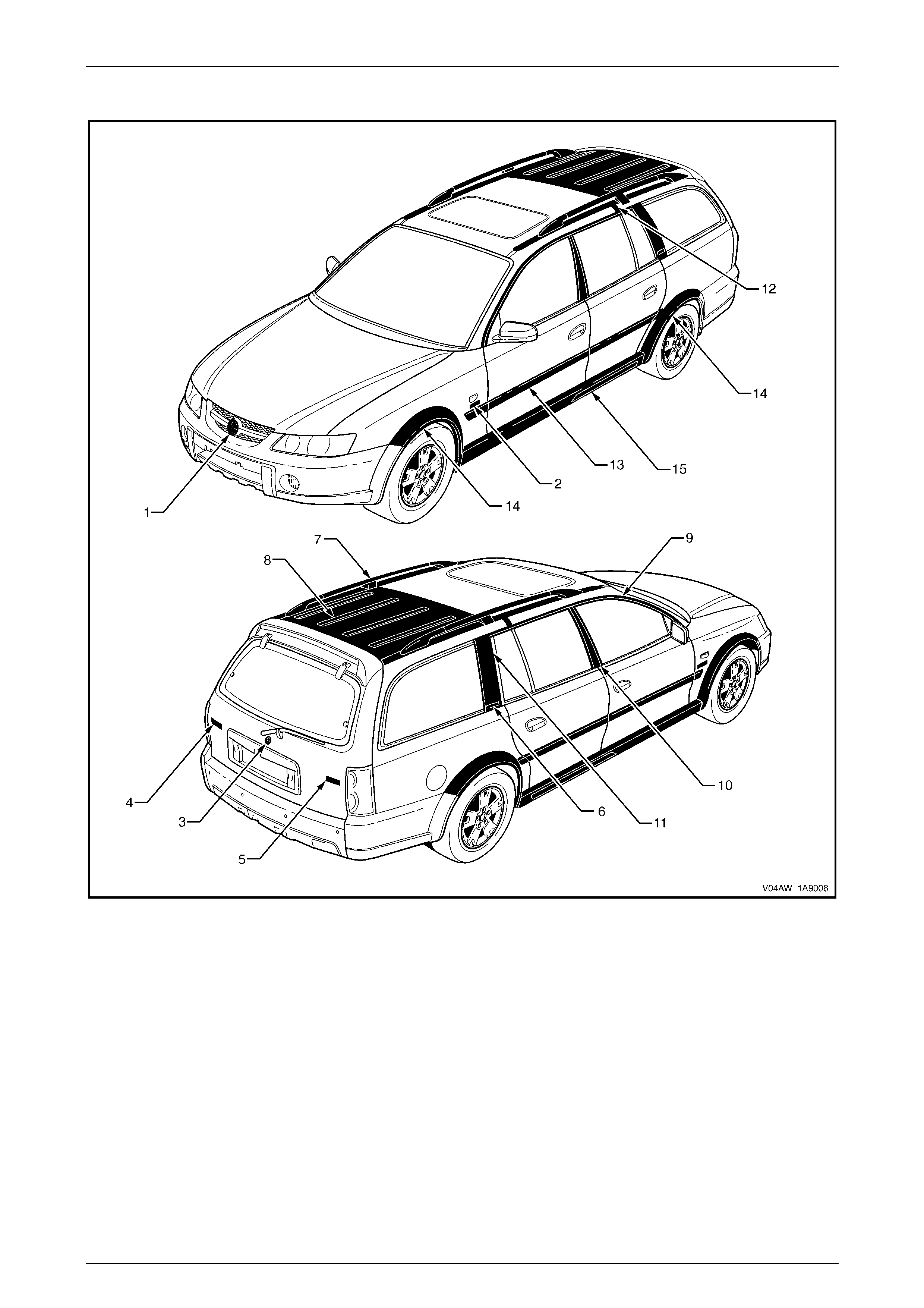
High Level
Figure 1A9 – 2

Exterior Ornamentation Page 1A9–7
Page 1A9–7
Legend
Description
1 Radiator Grille Emblem: Lion
2 Fender Name Plate: V8
3 Rear Compartment Lid Embl em: Lion Emblem
4 Lift gat e Name Plate, LH: Adventra
5 Lift gat e Name Plate, RH: LX8
6 Rear Quarter Window Applique Name Plate: CrossXTrac
7 Roof Rack Carri er Ass embly
8 Luggage Carrier
9 Door Opening Moulding
10 Rear Quarter Window Applique Assembl y
11 Centre Pillar Upper Finisher Assembly
12 Roof Joint Finisher
13 Body Side Moulding
14 Wheelhouse Opening Flare
15 Rocker Panel Moulding Assembly
Refer To:
2.1 Radiator Grille Embl em
2.2 Fender Name Plate
2.3 Liftgate Emblem
2.4 Liftgat e Name Plate, LH
2.5 Liftgat e Name Plate, RH
2.6 Rear Quarter Window Appli que Assembly Nam e Plate
2.7 Roof Rack Carrier Ass em bl y
2.8 Luggage Carrier
2.9 Door Opening Moulding
2.10 Rear Quarter Window Applique Ass em bly
Refer to Section 1A9, 3.10 Centre Pillar Upper Finisher Assembly
in the MY 2003 VY and V2 Series Service Information.
Refer to Section 1A9, 3.11 Roof Joint Finis her in the MY 2003 VY
and V2 Series Service Information.
2.11 Body Side Mouldings
2.12 Wheelhouse Opening Flare
2.13 Rocker Panel Moulding Assem bly
Exterior Ornamentation Page 1A9–8
Page 1A9–8
2 Service Operations
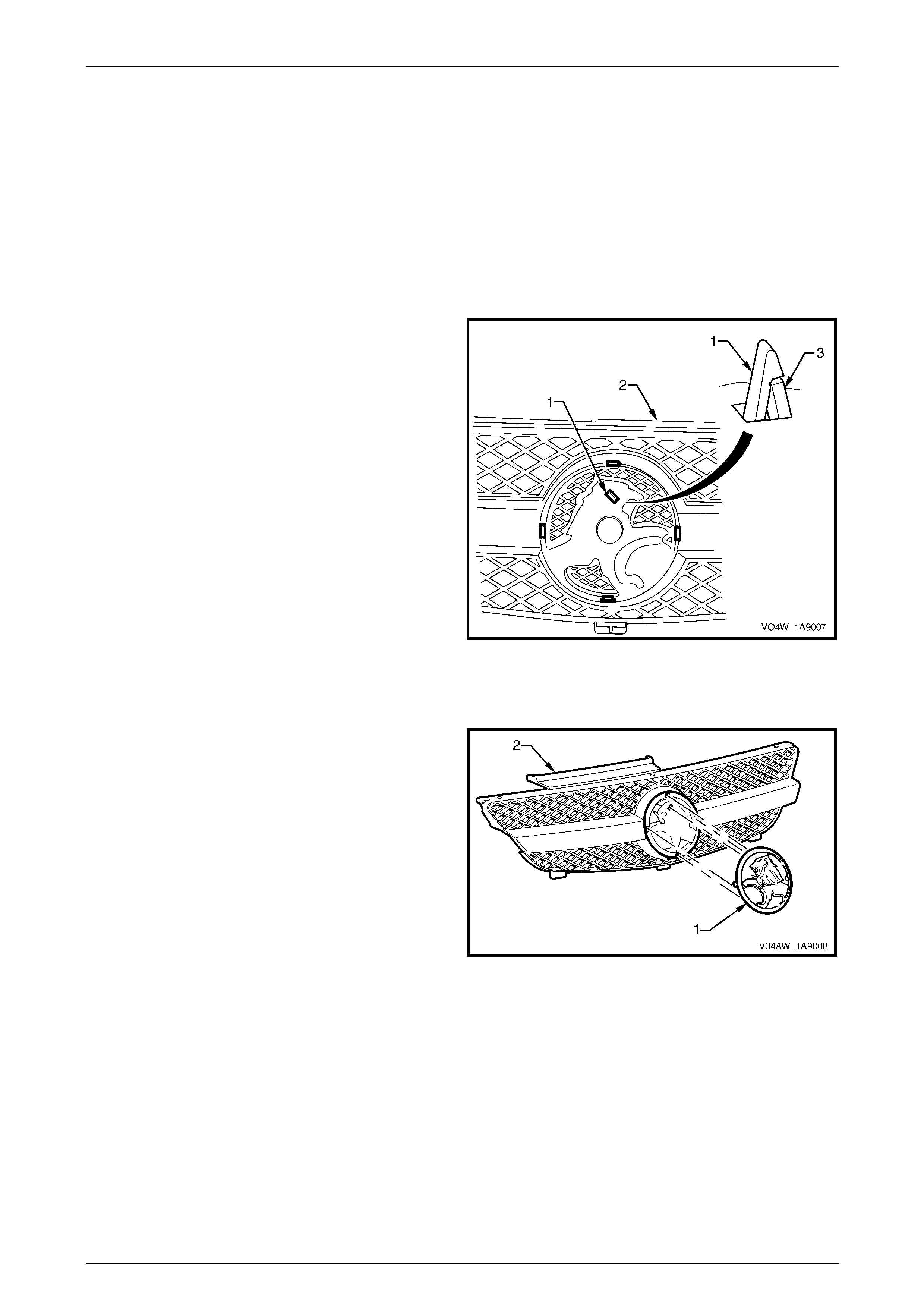
2.1 Radiator Grille Emblem
LT Section No. – XX-XXX
Remove
1 Remove the radiator grille, refer to Section 1C, Radiator Grille.
2 From the rear of the radiator grille assembly, depress
the retainer (1), five places, and remove the radiator
grille emblem from the grille assembly.
Figure 1A9 – 3
Reinstall
1 Align the emblem (1) by locating the retainers with
their corresponding holes in the grille assembly (2).
2 Fit the components together and ensure the retainers
are seated correctly.
Figure 1A9 – 4
Exterior Ornamentation Page 1A9–9
Page 1A9–9
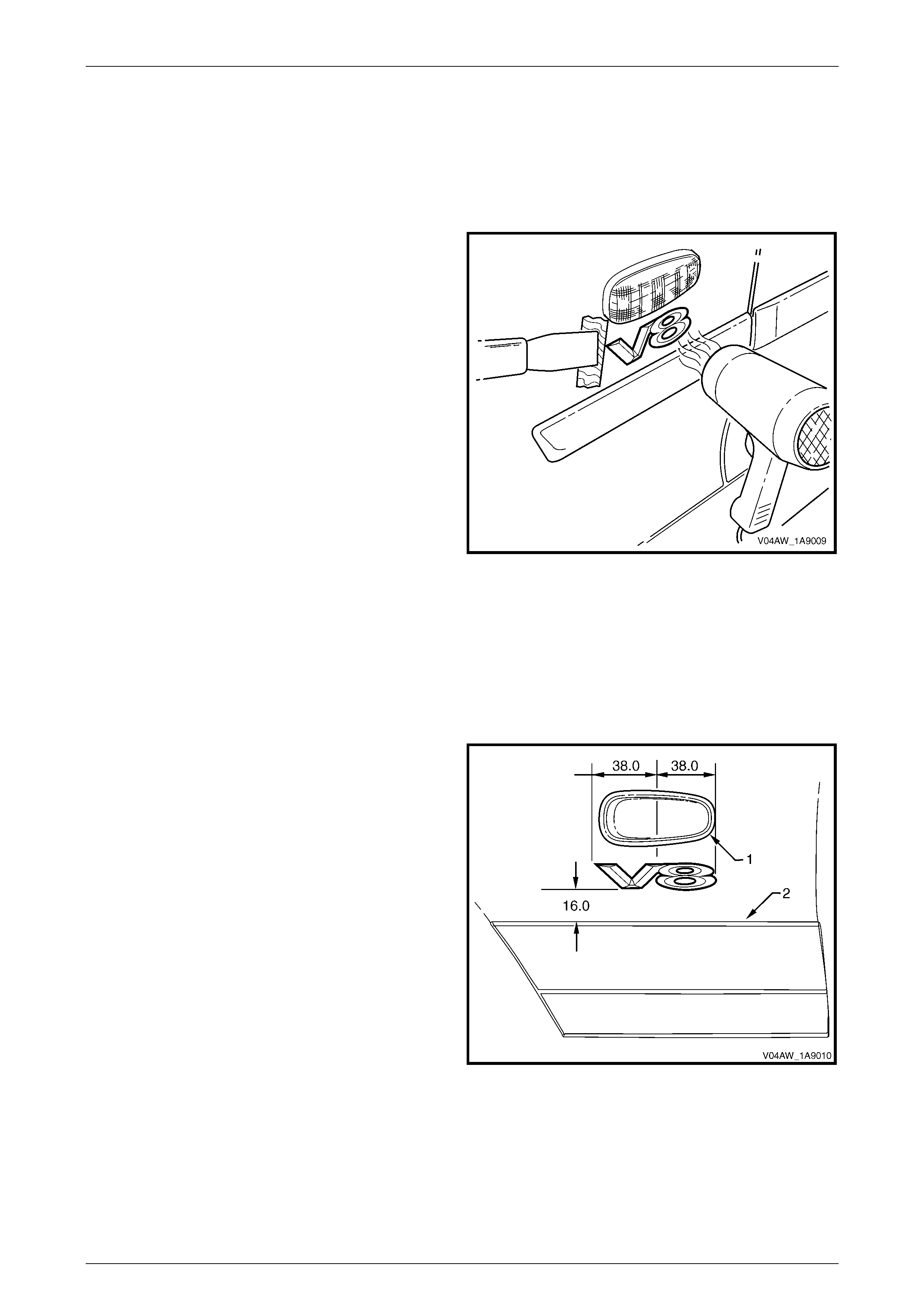
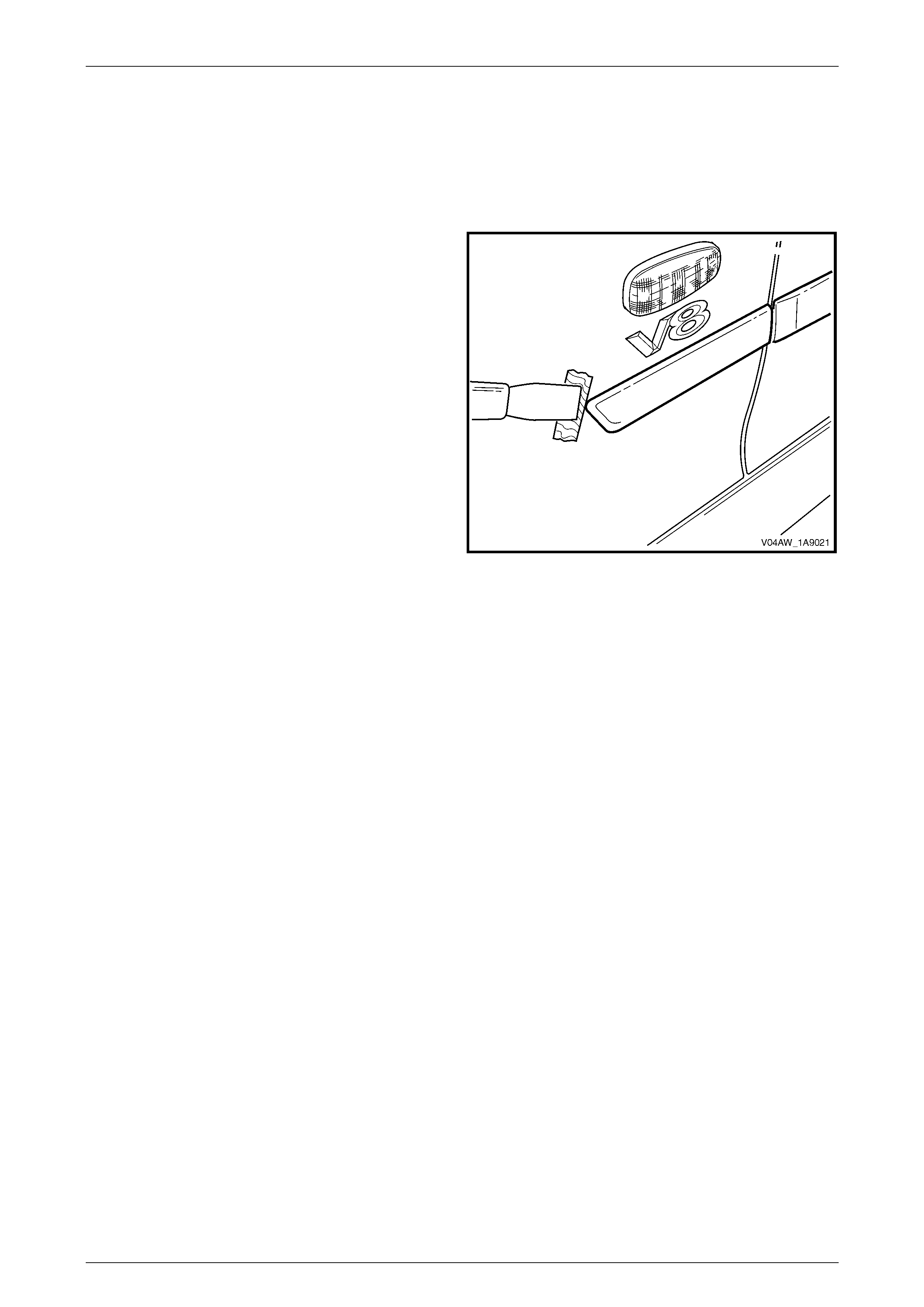
2.2 Fender Name Plate
LT Section No. – XX-XXX
Remove
1 Protect the paint and bodywork with tape or a rag.
2 To assist removal, warm the plate with a heat-lamp or
heat-gun to soften the adhesive.
3 Using a paint scraper or similar, carefully prise the
plate from the fender.
4 Remove any remaining double-sided tape from the
plate and/or fender and clean the surfaces with
Prepsol or equivalent.
Figure 1A9 – 5
Reinstall
1 If reusing the plate, apply new polyethylene double-sided tape such as 3M 4428 or equivalent to the back and trim
the edges of the tape slightly in from the edge of plate.
2 Clean the fender surface with Prepsol or equivalent.
3 Remove the backing paper from the double-sided tape.
4 Apply the plate in the position shown, measuring from
the front side turn signal lamp (1). Ensure it is
positioned parallel to the body side moulding (2).
5 Press firmly over the entire plate for at least 10
seconds to ensure maximum a dhes ion.
Figure 1A9 – 6
Exterior Ornamentation Page 1A9–10
Page 1A9–10
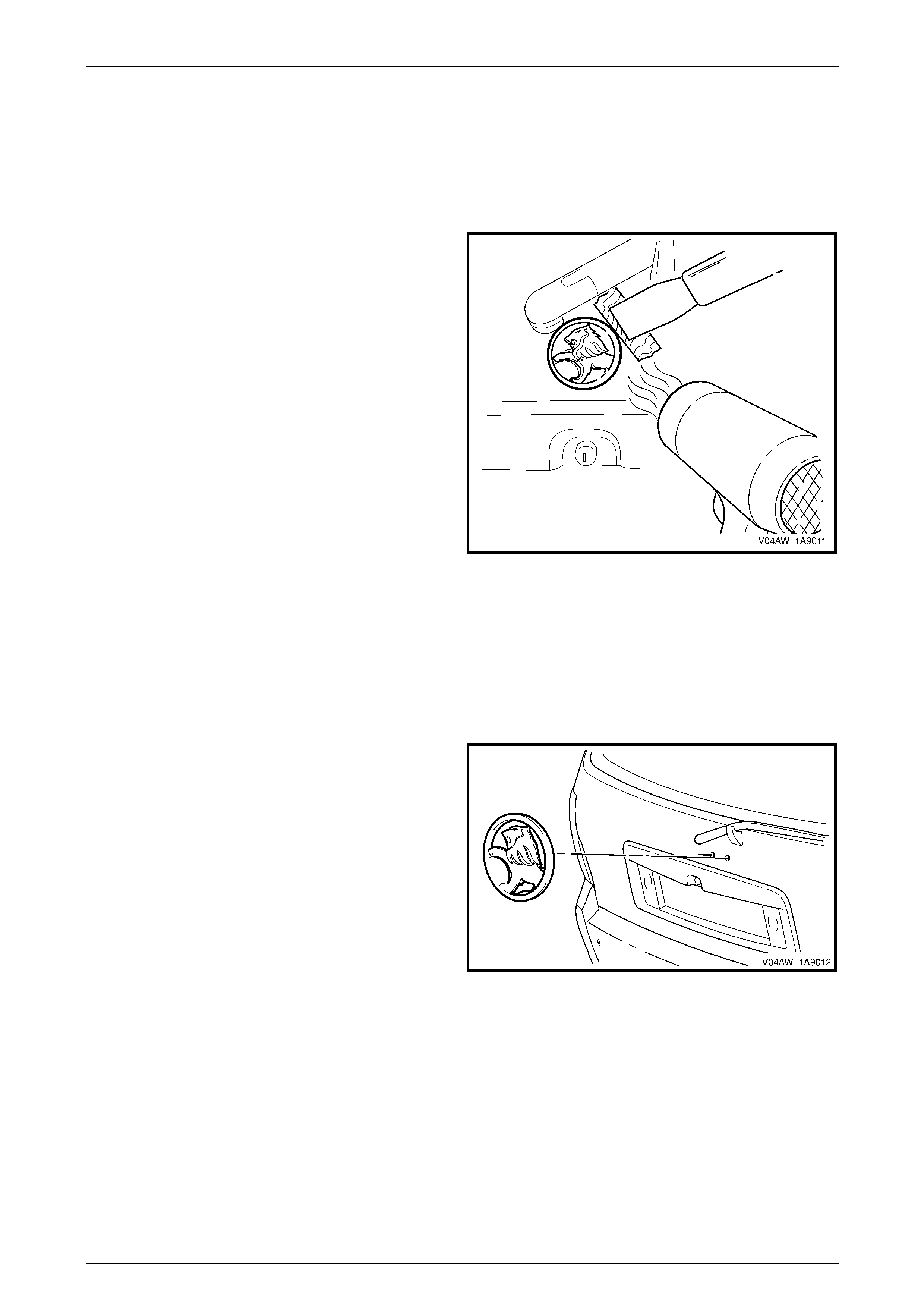
2.3 Liftgate Emblem
LT Section No. – XX-XXX
Remove
1 Protect the paint and bodywork with tape or a rag.
2 To assist removal, warm the emblem with a heat-lamp
or heat-gun to soften the adhesive.
3 Using a paint scraper or similar, carefully prise the
emblem from the liftgate .
NOTE
The emblem has two locating pins, take care not
to break them if the emblem is to be reused.
4 As required, remove any remaining double sided tape
from the emblem and/or liftgate and clean the surfaces
with Prepsol or equivalent.
Figure 1A9 – 7
Reinstall
1 If reusing the emblem, apply new polyethylene double-sided tape such as 3M 4428 or equivalent to the back and
the trim edges of the tape slightly in from the edge of the emblem.
2 Clean the panel surface with Prepsol or equivalent.
3 Remove the backing paper from the double-sided tape.
4 Apply the emblem in the position shown ensuring the
locating pins are correctly orientated with the locating
holes in the panel surface.
5 Press firmly over the entire emblem for at least 10
seconds to ensure maximum a dhes ion.
Figure 1A9 – 8
Exterior Ornamentation Page 1A9–11
Page 1A9–11
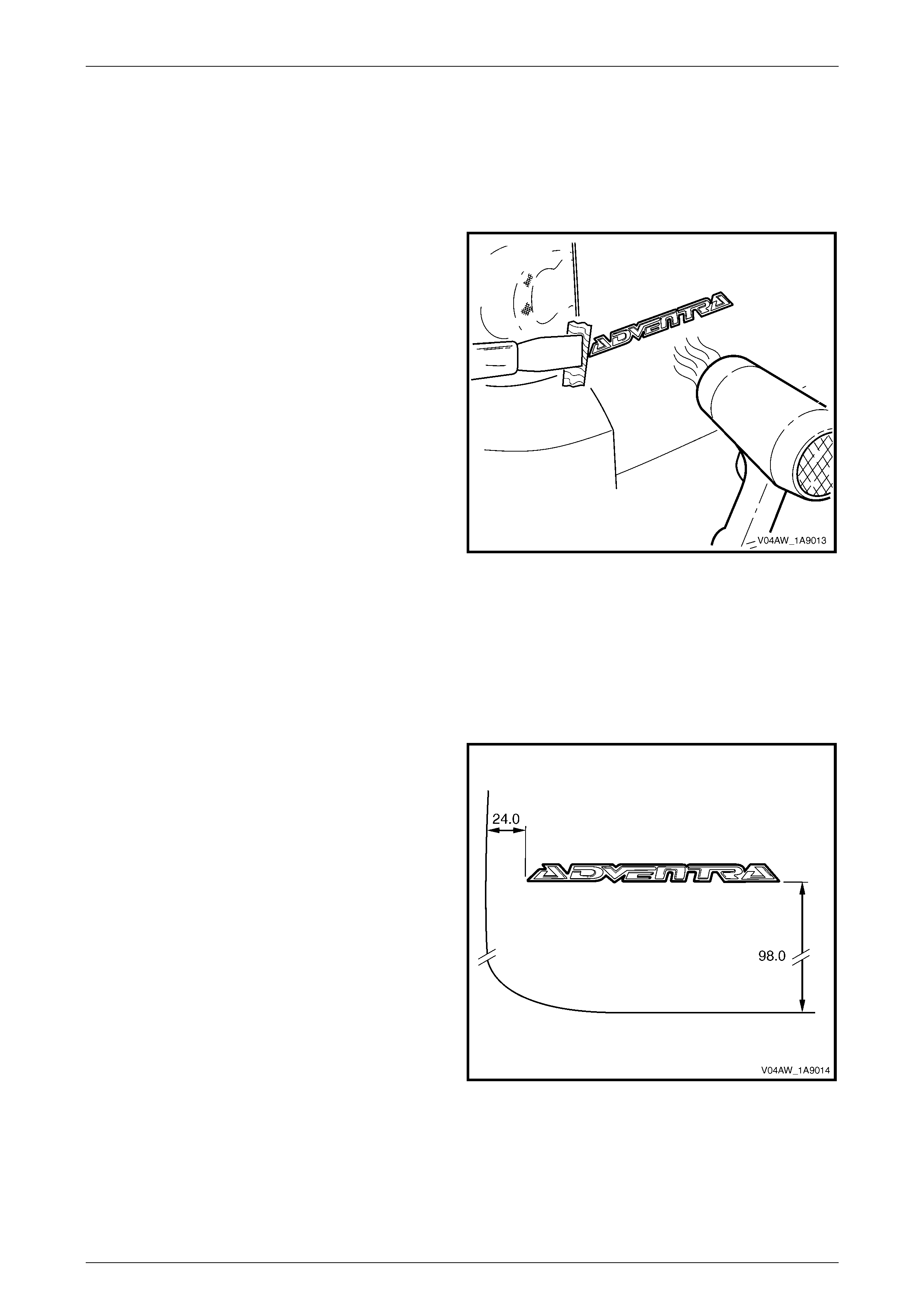
2.4 Liftgate Name Plate, LH
LT Section No. – XX-XXX
Remove
1 Protect the paint and bodywork with tape or a rag.
2 To assist removal, warm the emblem with a heat-lamp
or heat-gun to soften the adhesive.
3 Using a paint scraper or similar, carefully prise the
emblem from the liftgate .
4 As required, remove any remaining double-sided tape
from the name plate and/or liftgate and clean the
surfaces with Prepsol or equivalent.
Figure 1A9 – 9
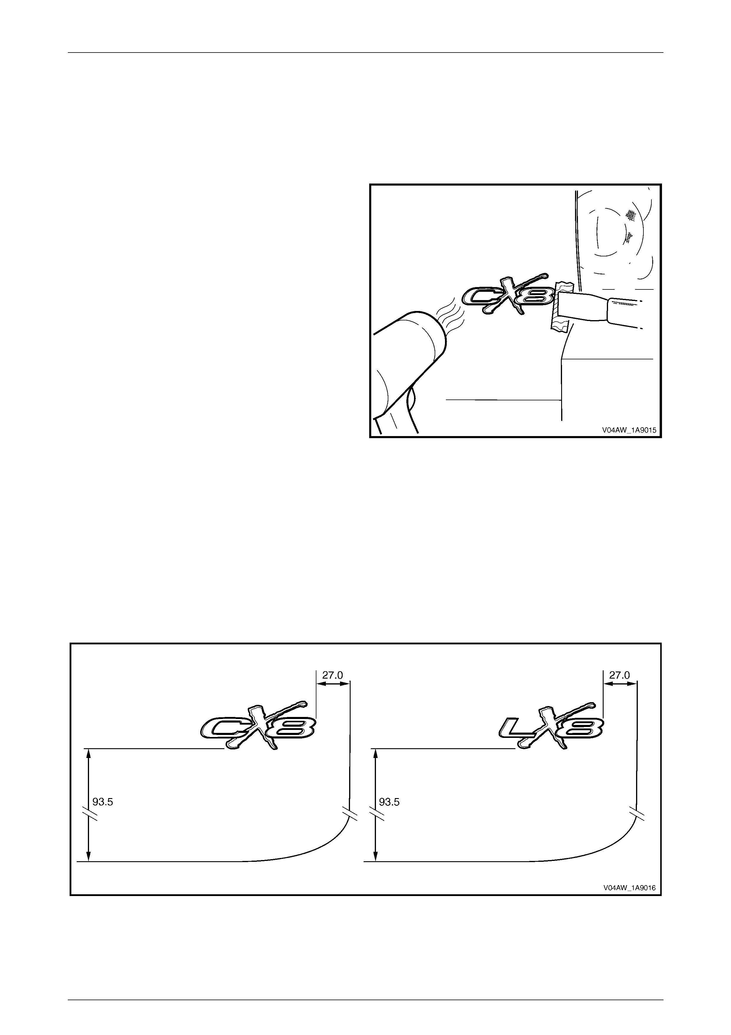
Reinstall
1 If reusing the name plate, apply new polyethylene double-sided tape such as 3M 4428 or equivalent to the back
and the trim edges of the tape slightly in from the edge of the name plate.
2 Clean the panel surface with Prepsol or equivalent.
3 Remove the backing paper from the double-sided tape.
4 Apply the name plate onto the right-hand side of the
liftgate in the position shown, ensur ing it is strai ght and
correctly aligned to the measurements.
5 Press firmly over the entire plate for at least 10
seconds to ensure maximum a dhes ion.
Figure 1A9 – 10
Exterior Ornamentation Page 1A9–12
Page 1A9–12
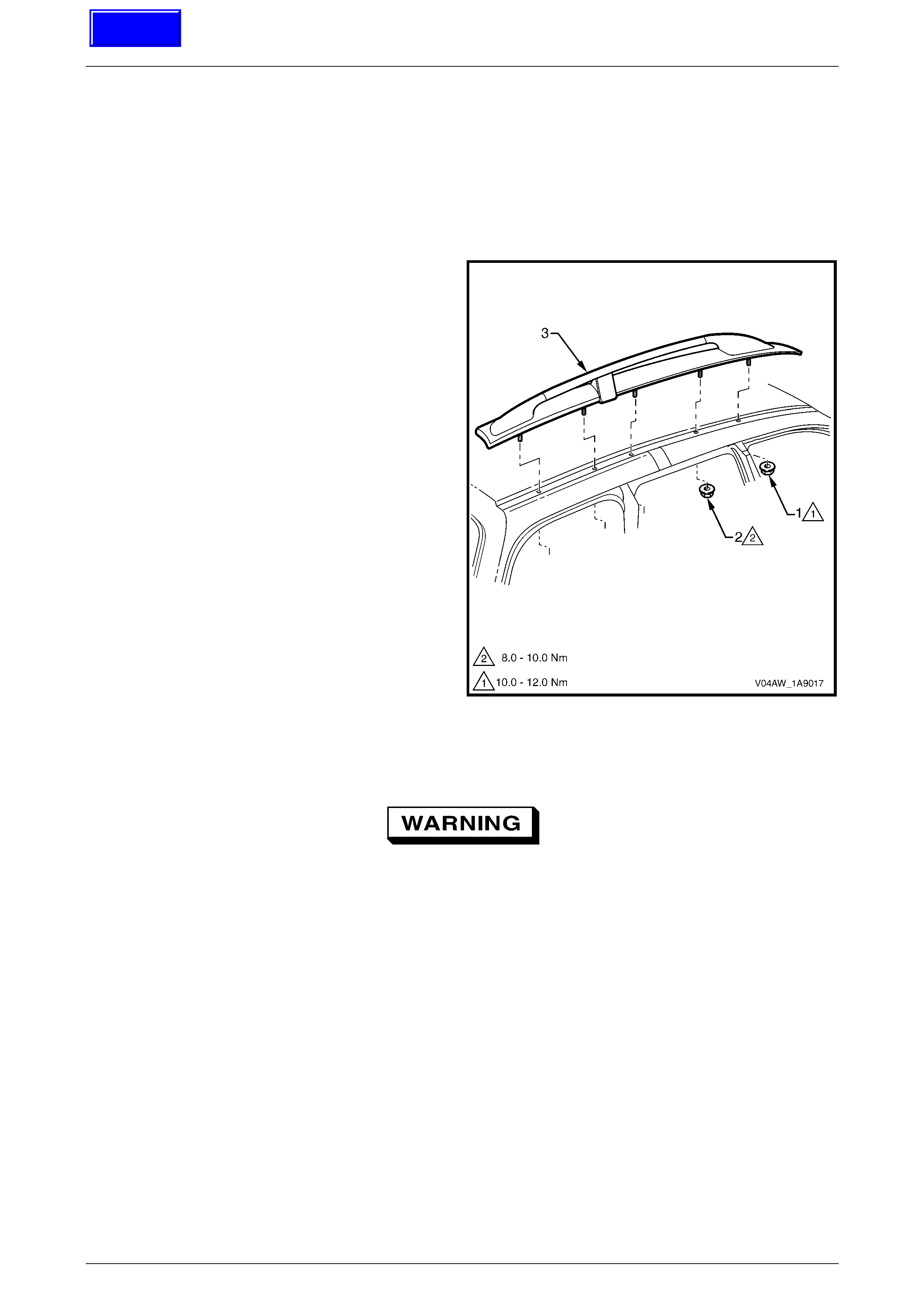
2.5 Liftgate Name Plate, RH
LT Section No. – XX-XXX
Remove
1 Protect the paint and bodywork with tape or a rag.
2 To assist removal, warm the emblem with a heat-lamp
or heat-gun to soften the adhesive.
3 Using a paint scraper or similar, carefully prise the
emblem from the liftgate .
4 As required, remove any remaining double-sided tape
from the name plate and/or liftgate and clean the
surfaces with Prepsol or equivalent.
Figure 1A9 – 11
Reinstall
1 If reusing the name plate, apply new polyethylene double-sided tape such as 3M 4428 or equivalent to the back
and the trim edges of the tape slightly in from the edge of the name plate.
2 Clean the panel surface with Prepsol or equivalent.
3 Remove the backing paper from the double-sided tape.
4 Apply the name plate onto the right-hand side of the liftgate in the position shown, ensuring it is straight and is
correctly aligned to the measurements.
5 Press firmly over the entire plate for at least 10 seconds to ensure maximum adhesion.
Figure 1A9 – 12

Exterior Ornamentation Page 1A9–13
Page 1A9–13
2.6 Rear Quarter Window Applique
Assembly Name Plate
LT Section No. – XX-XXX
Remove
1 Protect the paint and bodywork with tape or a rag.
2 To assist removal, warm the plate with a heat-lamp or
heat-gun to soften the adhesive.
3 Using a paint scraper or similar, carefully prise the
plate from the rear quarter window applique.
4 Remove any remaining double-sided tape from the
plate and/or applique and clean the surfaces with
Prepsol or equivalent.
Figure 1A9 – 13
Reinstall
1 If reusing the plate, apply new polyethylene double-sided tape such as 3M 4428 or equivalent to the back and trim
the edges of the tape slightly in from the edge of plate.
2 Clean the applique surface with Prepsol or equivalent.
3 Remove the backing paper from the double-sided tape.
4 Apply the plate in the cavity on the applique.
5 Press firmly over the entire plate for at least 10 seconds to ensure maximum adhesion.
Exterior Ornamentation Page 1A9–14
Page 1A9–14
2.7 Roof Rack Carrier Assembl y
LT Section No. – XX-XXX
Remove
1 Remove the headlining from the vehicle, refer to Section 1A8 Headlining and Interior Trim.
2 From inside the vehicle, remove the nut (1), one place
and (2), four places, attaching the roof rack carrier
assembly (3) to the roof panel.
3 Lift the rear of the assembly up until the studs are free
and then slide the rail rearward.
Figure 1A9 – 14
Disassemble
• To avoid installation problems, only the
components described herein must be
disassembled.
• Correct alignment of the components is
critical to avoid incorrect fitment when
installed.
• Take care when handling the roof rack
carrier assembly and its components.
NOTE
A new roof rack carrier service assembly is
supplied with the moulding assemblies unpainted.
To enable painting, the roof rail will require
removal.
Techline

Exterior Ornamentation Page 1A9–15
Page 1A9–15
1 From the underside of the roof rack carrier assembly,
carefully mark or scribe the position of the roof rail (1)
to the moulding assem bly (2).
2 Remove the screw (1), four places only, attaching the
roof rail (2) to the moulding assembly (3), refer to
Figure 1A9 – 16.
3 Remove the roof rail.
4 As required, remove the spacer (4) and O-ring (5),
three places, from the support assembly, refer to
View A.
5 As required, remove the O-ring (6), one place each at
the front and rear of the roof rail, refer to View B.
6 The foam seal (7) in three places, is not serviced but
may be remove d carefull y if required.
No further disassembly is permitted.
Figure 1A9 – 15
Figure 1A9 – 16
Exterior Ornamentation Page 1A9–16
Page 1A9–16
Reassemble
1 If the moulding assembly requires painting, mask the support assembly. Refer to Section 1D, 2.1 Paint Systems for
painting instruction, noting that the moulding assembly is manufactured from ABS plastic.
2 Install the spacers, O-rings and seals as required.
3 Fit the roof rail into the moulding assembly.
3 Install the attaching screws, check for correct alignment of the components to the marks and tighten the screws to
the correct torque specification.
Roof rail assembly attaching screw
torque specific atio n .............................................6.0 Nm
Reinstall
Reinstallation of the roof rack carrier assembly is the reverse of the removal procedure, noting the following:
1 Ensure the foam seals are not damaged and are correctly seated and that the O-rings are fitted to each of the
studs.
2 Install the roof rack carrier assembly and hand tighten each of the nuts.
3 Check for correct fitment and alignment of the roof rack carrier assembly to the vehicle. As required, adjust its
position or remove and readjust the position of the roof rail to the moulding assembly.
4 Repeat steps 2 and 3 until correct alignment is achieved.
5 Tighten the nuts to the correct torque specification.
Roof rack carrier assembly front
attaching nut torque specification............. 8.0 – 10.0 Nm
Roof rack carrier assembly rear
attaching nut torque specification........... 10.0 – 12.0 Nm
Exterior Ornamentation Page 1A9–17
Page 1A9–17
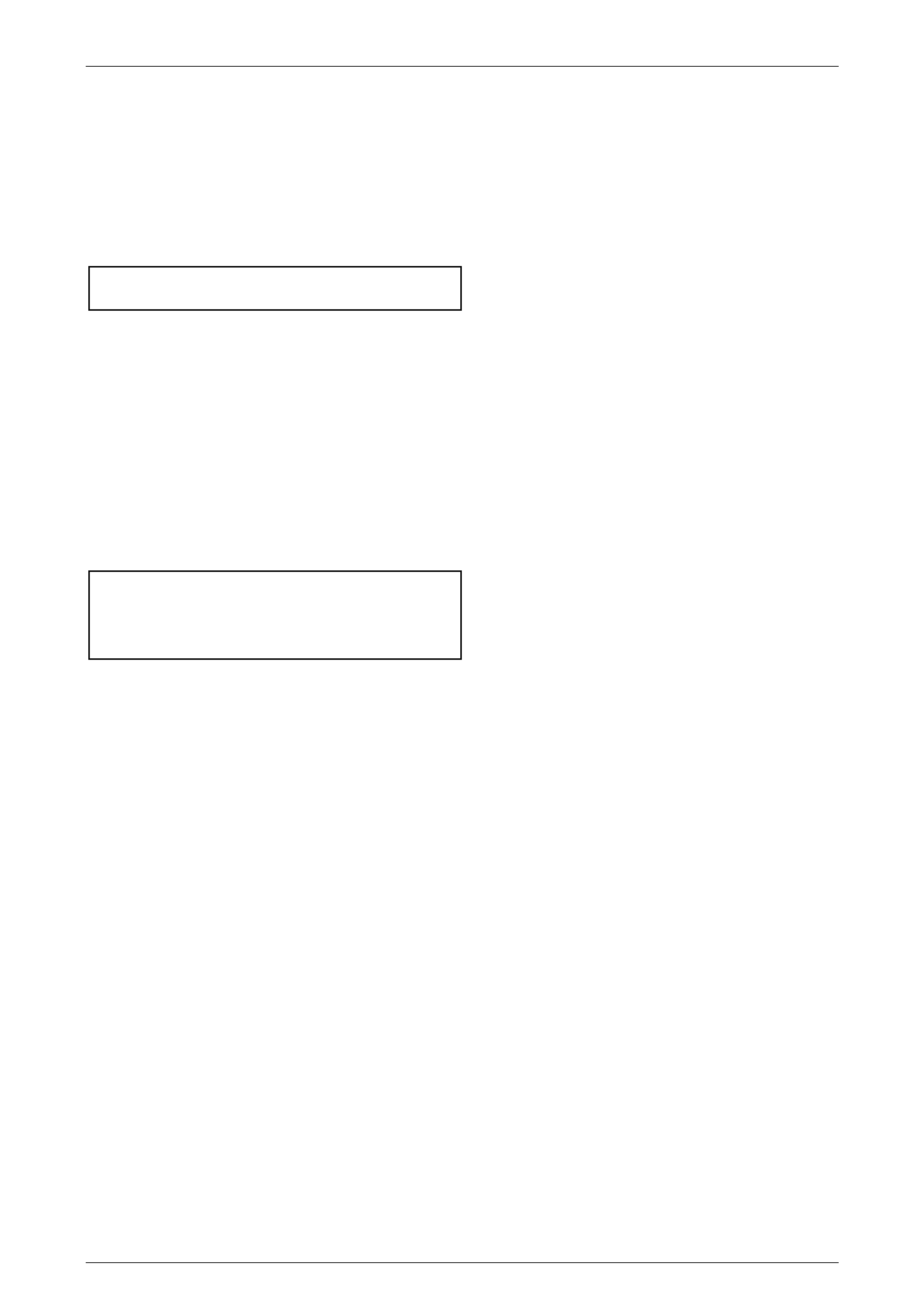
2.8 Luggage Carrier
LT Section No. – XX-XXX
Remove
1 Remove the headlining, refer to Section 1A8, Headlining and Interior Trim.
2 Remove the nut (1), 10 places, from inside the vehicle, refer to Figure 1A9 – 17.
3 With the aid of an assistant, carefully lift the luggage carrier (2) off the vehicle.
Figure 1A9 – 17
Reinstall
Reinstallation of the luggage carrier is the reverse of the removal procedure, noting the following:
1 Ensure the foam seals are not damaged and is correctly seated and that the O-ring seals are fitted to each of the
studs.
2 Tighten the nuts to the correct torque specification.
Luggage carrier attaching nut
torque specification ................................ 10.0 – 12.0 Nm
Exterior Ornamentation Page 1A9–18
Page 1A9–18
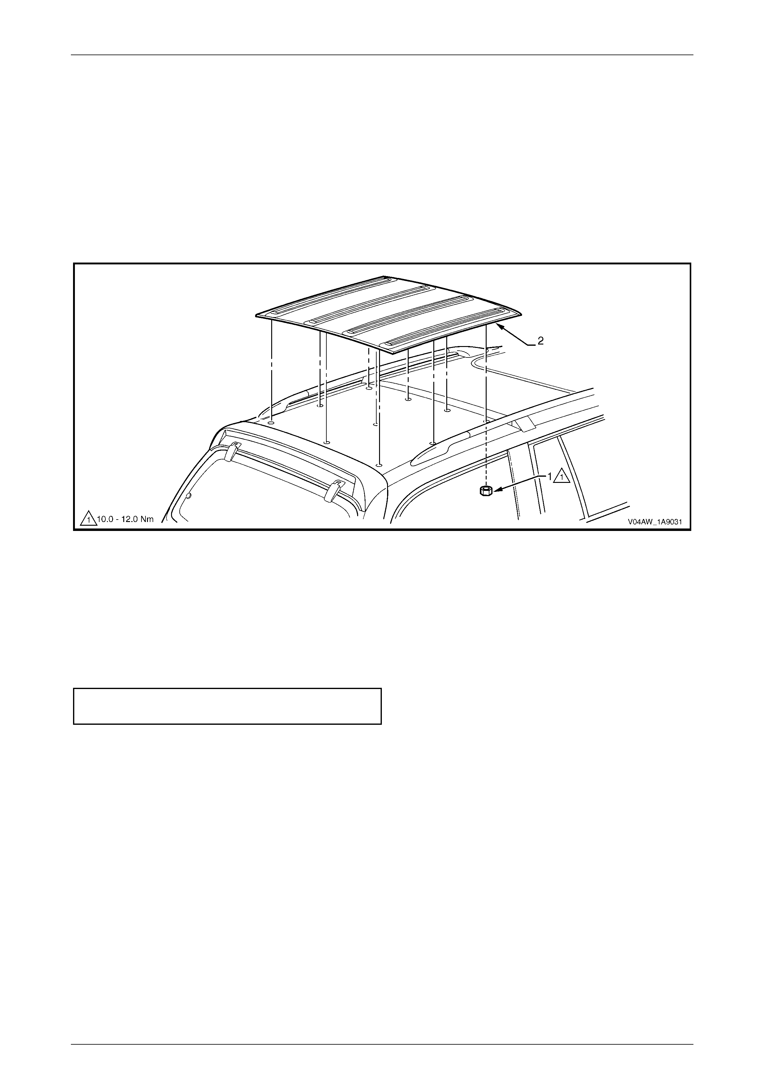
2.9 Door Opening Moulding
LT Section No. – XX-XXX
Remove
1 Open the front and rear doors on the relevant side of
the vehicle.
2 Beginning at each end and working towards the
middle, remove the screw (1), 11 places, attaching the
door opening moulding (2) to the body.
3 Carefully remove the moulding, disengaging the
quarter window assembly tab (3).
Figure 1A9 – 18
Reinstall
Reinstallation of the door opening moulding is the reverse of the removal procedure noting the following.
1 When installing the screws, begin at the rear and work forward.
2 Tighten the screws to the correct torque specification..
NOTE
The screws are encapsulated with a wax sealer.
It is recommended that the screws be replaced
once removed, however if this is impractical,
apply a small amount of sealer to the end of the
thread.
Door opening moulding attaching screw
torque specific atio n ....................................0.3 – 1.0 Nm
Exterior Ornamentation Page 1A9–19
Page 1A9–19
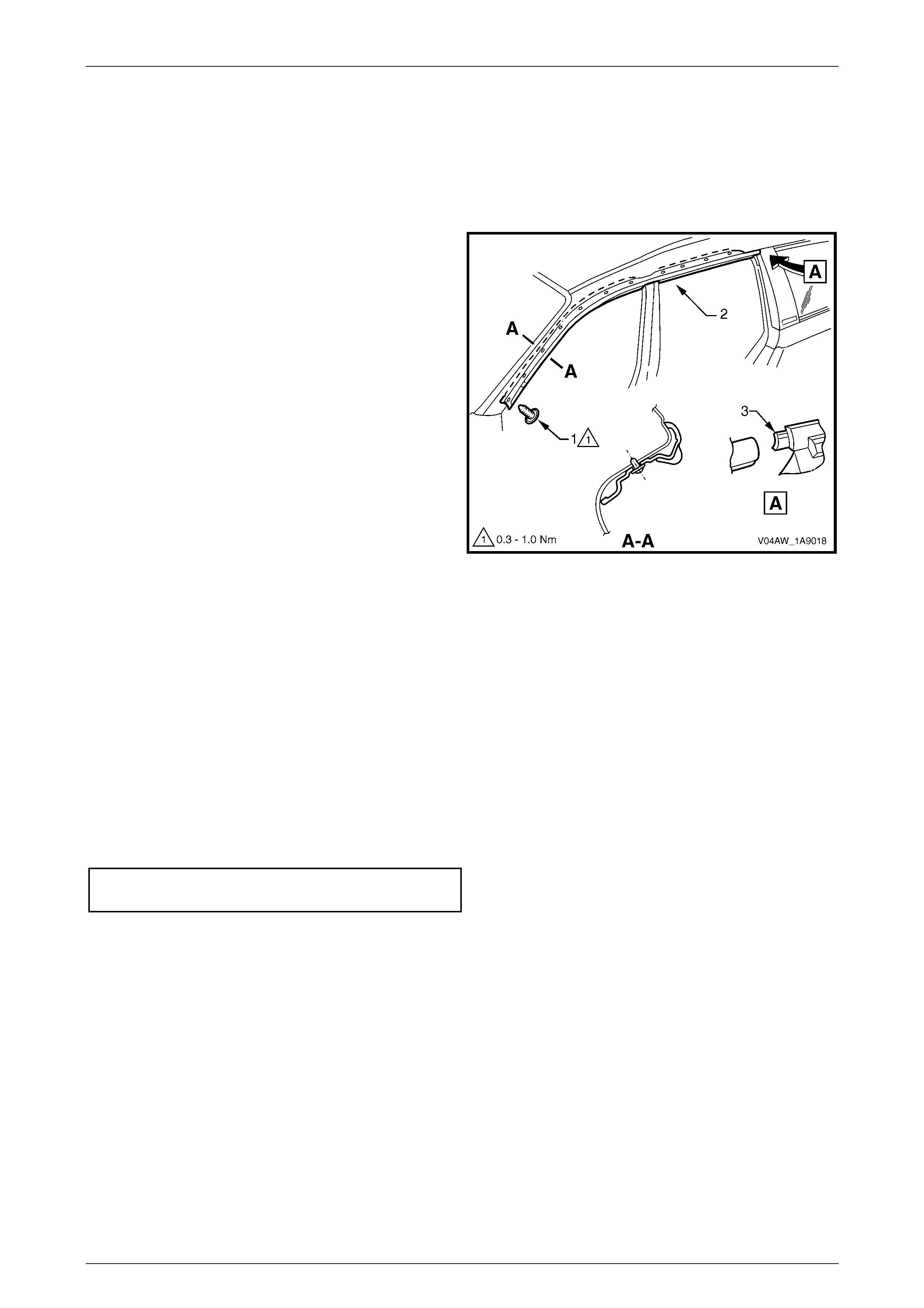
2.10 Rear Quarter Window Applique
Assembly
LT Section No. – XX-XXX
Remove
1 Open the rear door on relevant side of the vehicle.
2 Gently prise top of rear quarter window applique
assembly (1) out to disengage it from the rear quarter
window assembly (2).
3 Holding the top of applique out, slide it up the out of
the holes in the moulding (3).
Figure 1A9 – 19
Reinstall
Reinstallation of the rear quarter window applique assembly is the reverse of the removal procedure.
Techline
Exterior Ornamentation Page 1A9–20
Page 1A9–20
2.11 Body Side Mouldings
LT Section No. – XX-XXX
Remove
1 Protect the paint and bodywork with tape or a rag.
2 Using a paint scraper or similar, begin at one end and
carefully prise the moulding from the panel, cutting
through the double sided tape and adhesive.
NOTE
As an alternative, carefully use a length of piano
wire to cut the adhesive in a similar way to
removing a windshield.
3 As required, remove any remaining double-sided tape
and adhesive from the moulding and/or panel. Clean
the surfaces with Prepsol or equivalent.
Figure 1A9 – 20
Reinstall
1 Place a mark on the rear edge of the fender and/or door panels at the three points, refer to Figure 1A9 – 22.
2 If a complete moulding set is to be fitted, or as required, apply a length of masking tape along the side of the
vehicle, level with the marks. Begin by affixing the tape at the rear of the rear door, hold it taut and away from the
vehicle, and affix it to each panel. Ensure it is straight and then smooth it down along its length.
3 If reusing the moulding, apply new acrylic double-sided tape (1) such as 3M 5344 along the back of the moulding.
4 Apply two 3.0 mm diameter beads of urethane adhesive such as Expandite Betaseal 554.02, Sikaflex Drive or
equivalent over the entire length of moulding (2 and 3), refer to Section AA-.
NOTE
Refer to any further directions supplied with the
urethane adhesive.
5 Affix the moulding to the vehicle in the correct positions, aligning the lower edge with the masking tape (if fitted).
• For the fender moulding begin at the rear edge, aligning to the dimension at Section B-B.
• For the front door moulding begin at the front edge of the front door, aligning to the dimension at Section B-B.
• For the rear door moulding begin at the front edge of the rear door, aligning to the dimension at Section C-C.
• For the quarter panel moulding begin at the front edge of the quarter panel, aligning to the dimension at
Section D-D.
6 Press firmly over the length of the moulding(s) at the double-sided tape to ensure maximum adhesion.
Exterior Ornamentation Page 1A9–21
Page 1A9–21
Figure 1A9 – 21
Exterior Ornamentation Page 1A9–22
Page 1A9–22
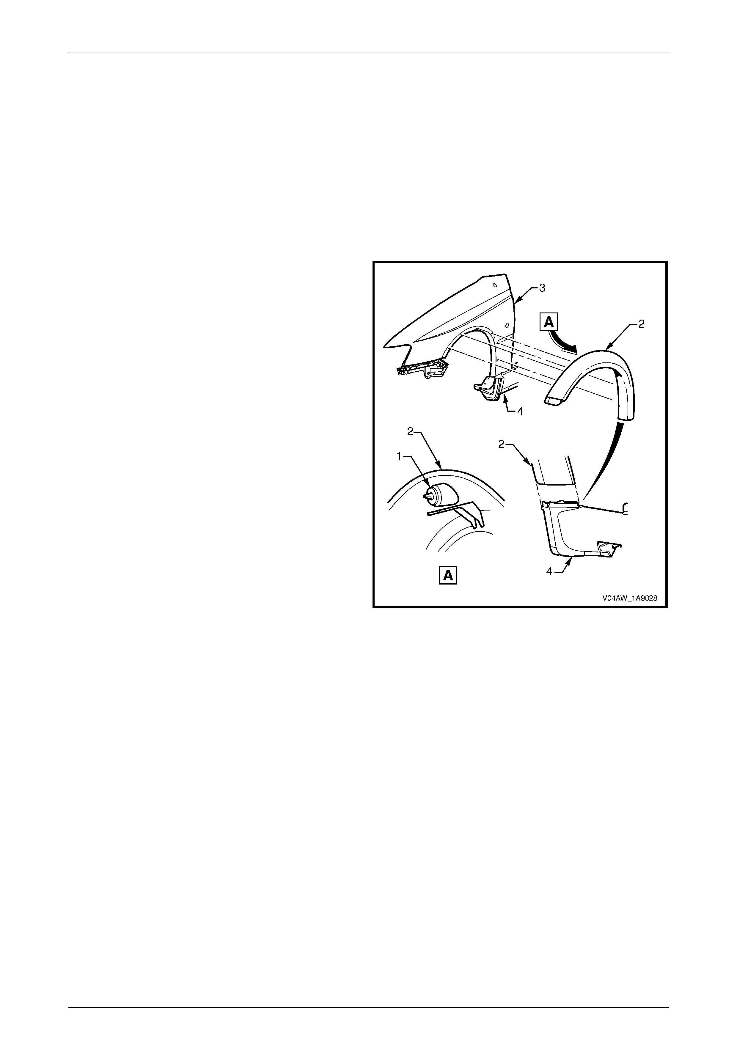
2.12 Wheelhouse Opening Flare Assembly
LT Section No. – XX-XXX
Front
Remove
1 Remove the front corner of the front bumper fascia, refer to Section 1D Bump er Bars.
2 Remove the front wheelhouse liner, refer to Section 1A1 Body.
3 From behind the fender squeeze the clip (1), six
places, and pull the flare (2) away from the fender (3),
working from the front to the back of the vehicle.
4 Lift the flare away from the rocker panel (4).
Figure 1A9 – 22
Reinstall
1 Ensure the flare assembly is seated correctly in the front bumper fascia guide and the rocker panel skirt.
2 Push the flare assembly towards the fender, engaging all of the retainers.
3 Replace the wheelhouse liner, refer to Section 1A1 Body.
4 Replace the front bumper fascia, refer to Section 1D Bumper Bars.

Exterior Ornamentation Page 1A9–23
Page 1A9–23
Rear
Remove
1 Remove the front corner of the rear bumper fascia, refer to Section 1D Bump er Bars.
2 Remove the rear wheelhouse liner, refer to Section 1A1 Body.
3 From inside the wheelhouse squeeze the clip (1), six
places, and pull the flare (2) away from the fender (3),
working from the back to the front of the vehicle.
4 Lift the flare away from the rocker panel moulding
assembly (4).
Figure 1A9 – 23
Reinstall
1 Ensure the flare assembly is seated correctly in the rear bumper fascia guide and the rocker panel.
2 Push the flare assembly towards the fender, ensuring of the retainers are engage correctly.
3 Replace the wheelhouse liner, refer to Section 1A1 Body.
4 Replace the rear bumper fascia, refer to Section 1D Bumper Bars.
Exterior Ornamentation Page 1A9–24
Page 1A9–24
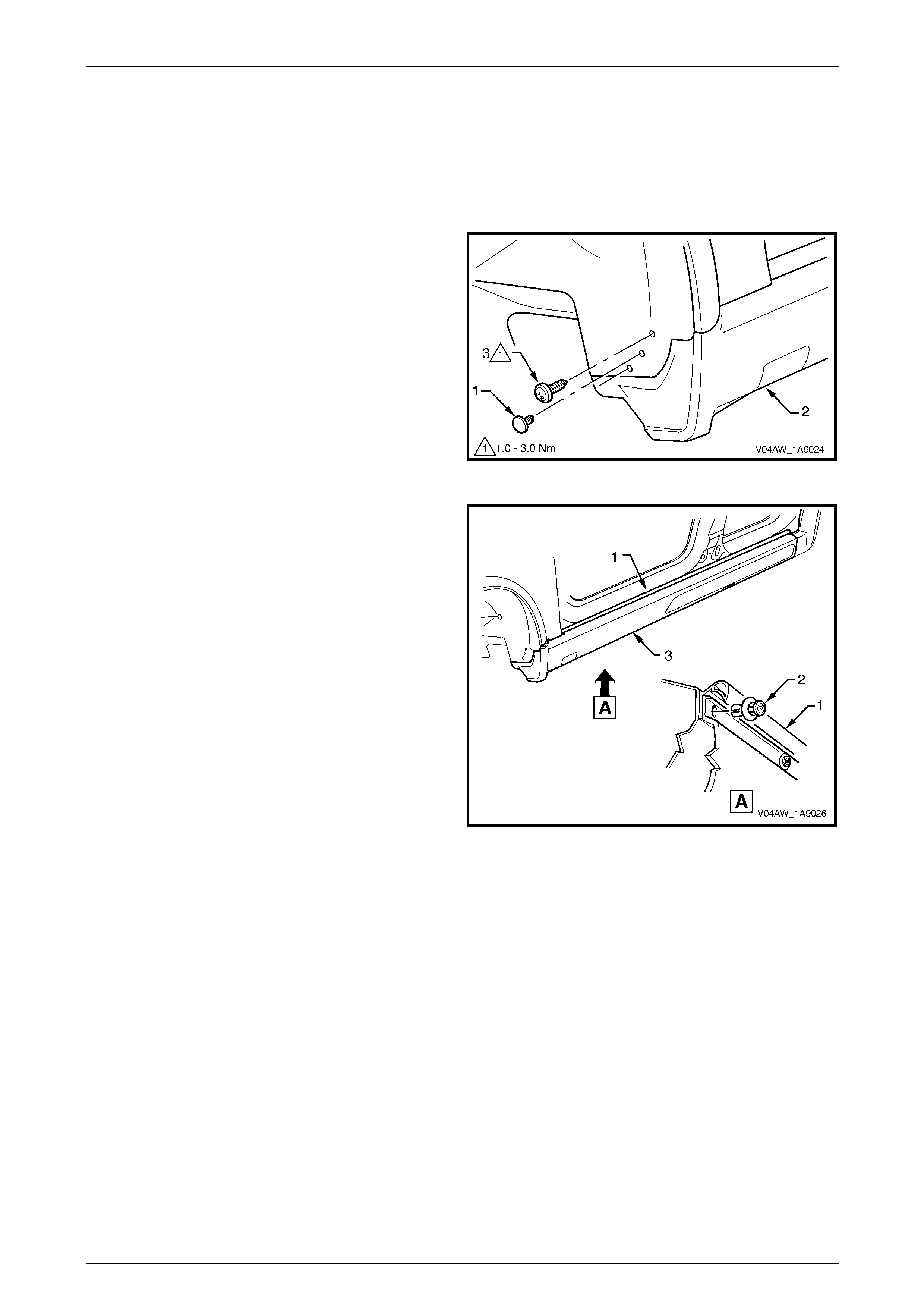
2.13 Rocker Panel Moulding Assembly
LT Section No. – XX-XXX
Remove
1 Remove the retainer (1) attaching the front rocker
panel moulding (2) to the wheelhouse liner.
2 Remove the screw (3), two places, attaching the front
rocker panel moulding to the wheelhouse liner.
Figure 1A9 – 24
3 Lift up the rocker panel weatherstrip (1) to gain access
and remove the retainer (2), nine places, attaching the
rocker panel moulding (3).
4 From underneath the vehicle, remove the screw (1),
seven places, from the retainer (2) under the
moulding (3), refer to Figure 1A9 – 26.
5 Remove the moulding.
6 If required, prise the nut (4), two places, from the
fender.
Figure 1A9 – 25
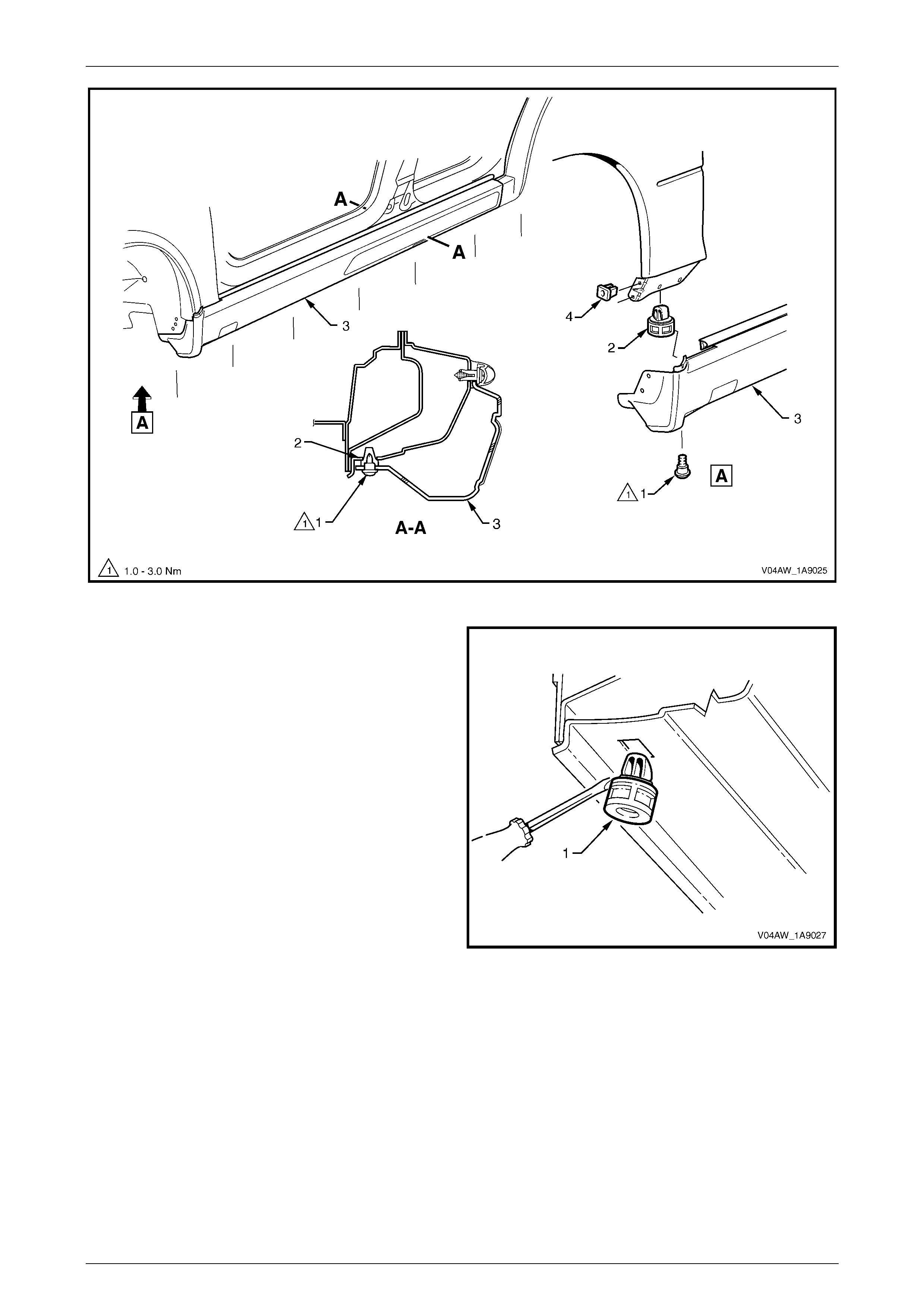
Exterior Ornamentation Page 1A9–25
Page 1A9–25
Figure 1A9 – 26
7 If required, remove the retainer (1), seven places, by
gently levering out from the body, taking care not to
damage paint work.
Figure 1A9 – 27
Exterior Ornamentation Page 1A9–26
Page 1A9–26
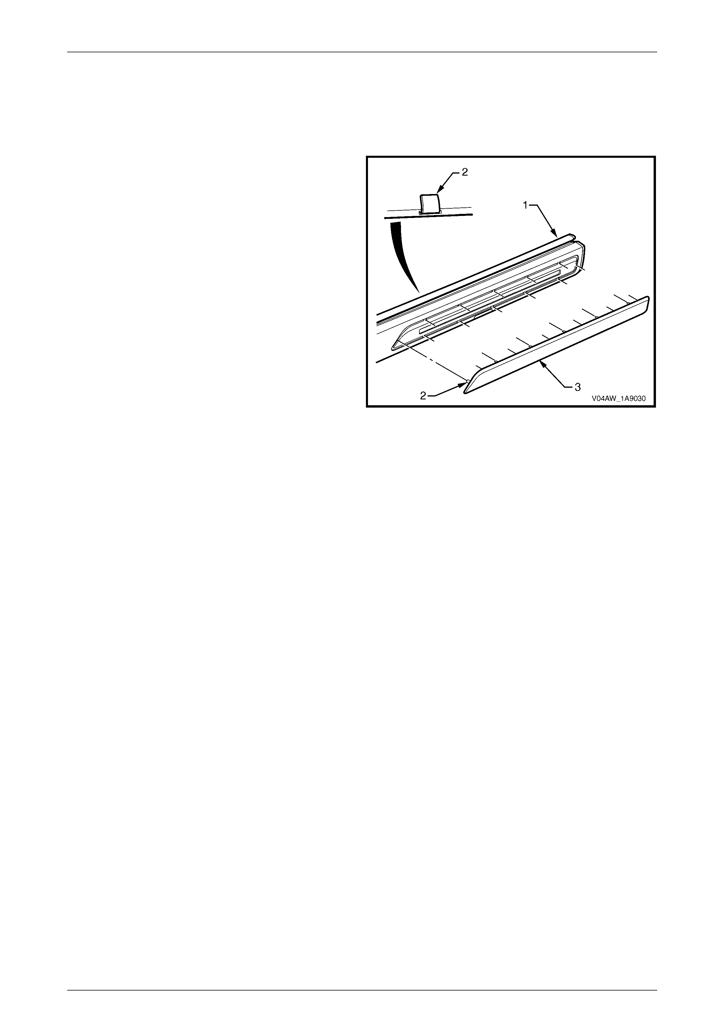
Disassemble
Rocker Panel Moulding Front Insert
Remove
1 From the inside of the rocker panel moulding (1) lift the
tab (2), 12 places, attaching the front insert (3).
2 Remove the insert from the moulding.
Figure 1A9 – 28
Reinstall
Reinstallation of the rocker panel moulding front insert is the reverse of the removal procedure, noting the following.
1 Reinstall the insert to the rocker panel moulding ensuring that all the tabs fit in the corresponding slots.
2 Fold the tabs over to secure the insert to the rocker panel moulding.
Exterior Ornamentation Page 1A9–27
Page 1A9–27
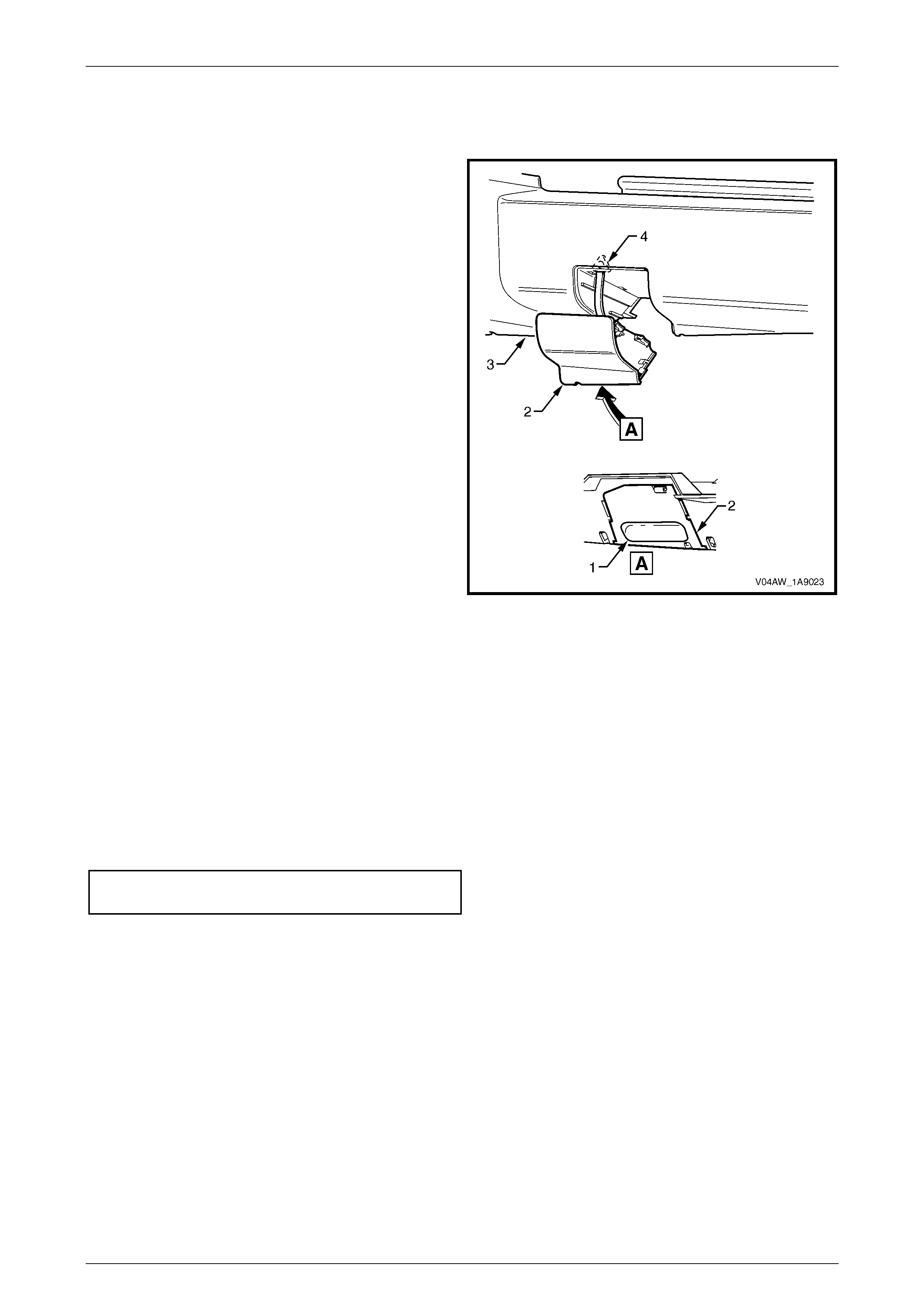
Jacking Access Cover
Remove
1 Holding with fingers in the indent (1) on the back of the
jacking access cover (2) pull out and away from the
rocker panel moulding (3) to remove.
2 If required, unattach the tether (4).
Figure 1A9 – 29
Reinstall
Reinstallation of the jacking access cover is the reverse of the removal procedure.
Reinstall
Reinstallation of the rocker panel moulding is the reverse of the removal procedure, noting the following.
1 Ensure the front moulding is correct ly seated in the ret ain ing clips.
2 Ensure the weatherstrip is seated correctly.
3 Tighten all fasteners to the correct torque specification.
Rocker panel moulding attaching screw
torque specific atio n ....................................1.0 – 3.0 Nm

Exterior Ornamentation Page 1A9–28
Page 1A9–28
3 Torque Wrench Specifications
Roof Rack Carrier Assembly Front Attaching Nut .......................8.0 – 10.0 Nm
Roof Rack Carrier Assembly Rear Attaching Nut ......................10.0 – 12.0 Nm
Roof Rail Assembly Attaching Screw ......................................................6.0 Nm
Luggage Carrier Attaching Nut ..................................................10.0 – 12.0 Nm
Door Opening Moulding Attaching Screw......................................0.3 – 1.0 Nm
Rocker Panel Moulding Attaching Screw.......................................1.0 – 3.0 Nm