
Bumper Ba r s Page 1D–1
Page 1D–1
Section 1D
Bumper Bars
ATTENTION
Before performing any service operation or other procedure described in this Section, refer to Section 00
Warnings, Cautions and Notes for correct workshop practices with regard to safety and/or property damage.
1 General Information............................................................................................................................... 2
2 Service Operations................................................................................................................................3
2.1 Paint Masking.........................................................................................................................................................3
Front Bumper..........................................................................................................................................................3
Rear Bumper...........................................................................................................................................................3
2.2 Front Bumper Fascia Undertray............................................................................................................................4
Remove ...................................................................................................................................................................4
Reinstall ..................................................................................................................................................................5
2.3 Front Bumper Fascia Assembly............................................................................................................................6
Remove ...................................................................................................................................................................6
Disassemble ...........................................................................................................................................................7
Recovery Point Cover.........................................................................................................................................7
Front Fog Lamp Opening Cover, Low Level.......................................................................................................8
Front Fog Lamp Assembly, High Level...............................................................................................................8
Front Bumper Fascia Insert................................................................................................................................9
Reinstall ................................................................................................................................................................10
2.4 Front Bumper Fascia Guide Assembly...............................................................................................................11
Remove .................................................................................................................................................................11
Reinstall ................................................................................................................................................................11
2.5 Front Bumper Fascia Support.............................................................................................................................12
Remove .................................................................................................................................................................12
Reinstall ................................................................................................................................................................12
2.6 Rear Bumper Fascia Assembly...........................................................................................................................13
Remove .................................................................................................................................................................13
Disassemble .........................................................................................................................................................15
Rear Bumper Fascia Filler................................................................................................................................15
Reverse Parking Aid Components....................................................................................................................15
Trailer Wiring Harness......................................................................................................................................16
Rear Bumper Fascia Insert...............................................................................................................................17
Reinstall ................................................................................................................................................................18
2.7 Rear Bumper Fascia Guide Assembly................................................................................................................19
Remove .................................................................................................................................................................19
Reinstall ................................................................................................................................................................19
2.8 Rear Bumper Fascia Upper Support...................................................................................................................20
Remove .................................................................................................................................................................20
Reinstall ................................................................................................................................................................20
2.9 Towbar Assembly.................................................................................................................................................21
Remove .................................................................................................................................................................21
Reinstall ................................................................................................................................................................21
3 Torque Wrench Specifications........................................................................................................... 22

Bumper Ba r s Page 1D–2
Page 1D–2
1 General Information
With the following exceptions, MY 2004 VY AWD Wagon Bumper Bars information carries over from MY 2003 VY and
V2 Series vehicles. For information not contained within this Section, refer to Section 1D, Bumper Bars in the MY 2003
VY and V2 Series Service Information.
• Front bumper extension undertray
• Front bumper fascia assembly
• Front bumper fascia guide assembly
• Front bumper fascia support
• Rear bumper fascia assembly
• Rear bumper fascia guide assembly
• Rear bumper fascia upper support
• Towbar Assembly
The bumper fascia assemblies fitted to MY 2004 VY AWD Wagon vehicles are constructed from polypropylene resin.
The front bumper fascia features a separate radiator grille assembly, refer to Section 1C Radiator Grille.
Fog lamps are installed on High Level vehicles and fog lamp covers on the Low Level vehicles.
Two bumper fascia supports are installed behind the front bumper fascia. These supports are attached to the steel front
bumper impact bar assembly. The bar assembly is attached directly to the front side rails and is designed to assist in the
dispersion of crash energy and plays an integral role with the vehicle’s safety systems.
All AWD Wagon vehicles are fitted with a towbar opening cover on the rear bumper fascia and a towbar assembly. The
towbar assembly can be fitted with a tow hitch.
The rear bumper fascia assembly includes four rear sensor assemblies for Reverse Parking Aid (RPA).
When reverse gear is selected, the sensors emit an ultra-sonic signal which is monitored by a control module. As the
sensors detect an object within their field of range, the system warns the driver by emitting an audible sound, which
increases in frequency, as the object becomes closer.
The sensors are supplied pre-painted in the
vehicle’s body colour and must not be
painted, refer to Section 1D, 2.1 Paint
Systems in the MY 2003 VY and V2 Series
Service Information and Reverse Parking Aid
Components in 2.6 Rear Bumper Fascia
Assembly.
For further inform ation on RPA, refer to Section 12F Reverse Parking Aid.
Bumper Ba r s Page 1D–3
Page 1D–3
2 Service Operations
2.1 Paint Masking
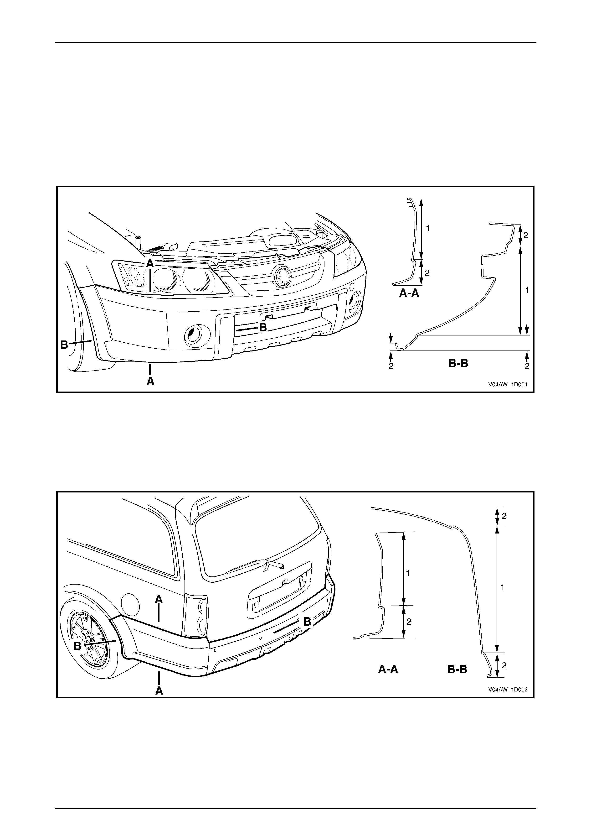
The following illustrations show the front and rear bumper fascia paint masking areas for AW D Wagon vehicles and are
provided to assist when painting a bumper fascia to match the factory finish.
Front Bumper
Figure 1D – 1
Legend
1 Body Colour 2 Unpainted
Rear Bumper
Figure 1D – 2
Legend
1 Body Colour 2 Unpainted
Bumper Ba r s Page 1D–4
Page 1D–4
2.2 Front Bumper Fascia Undertray
LT Section – XX-XXX
Remove
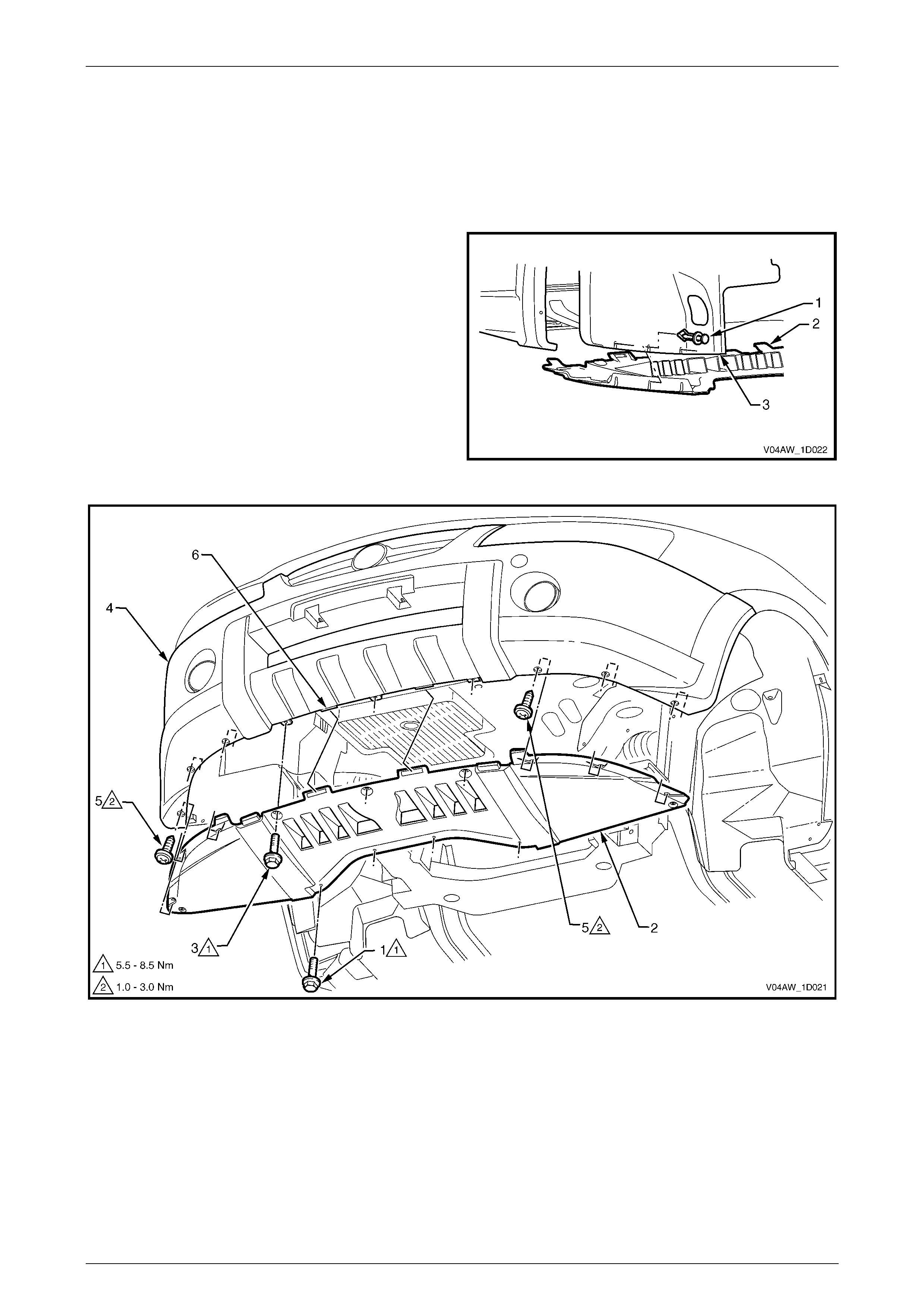
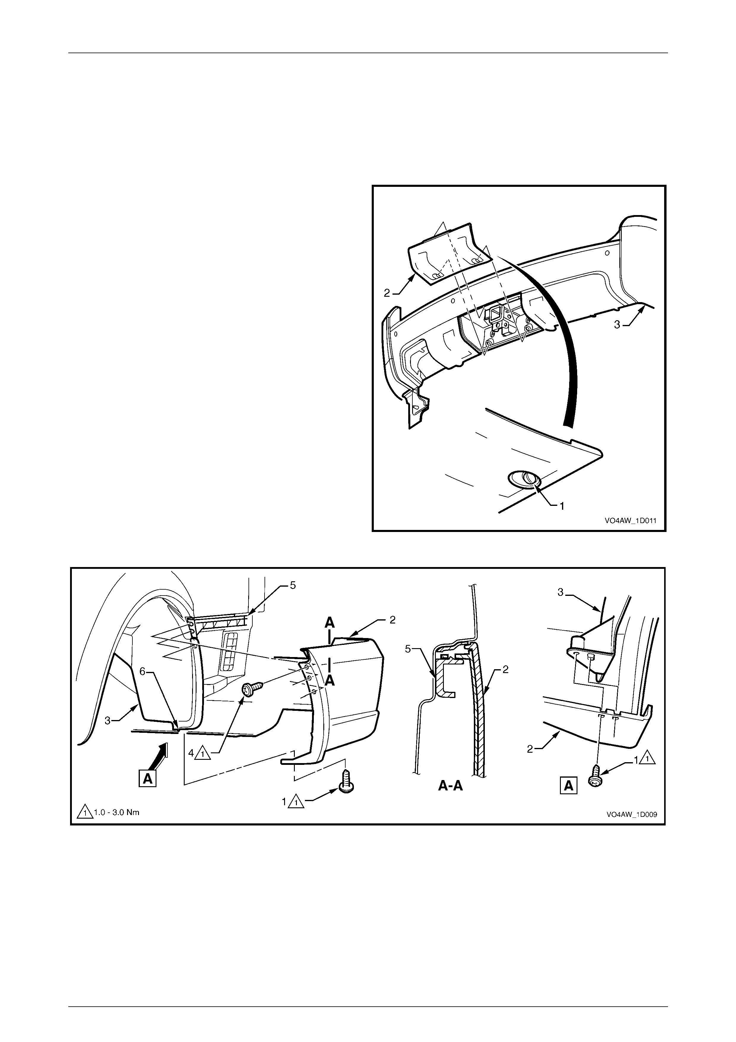
1 Remove the retainer (1), three places each side,
attaching the front bumper fascia undertray (2) to the
wheelhouse liner (3).
2 Remove the screw (1), four places, attaching the
undertray (2) to the crossmember, refer to
Figure 1D – 4.
3 Remove the screw (3), three places, attaching the
undertray to the centre of the front bumper fascia (4).
4 Remove the screw (5), three places each side,
attaching the undertray to the bumper fascia.
5 Remove the undertray by unhooking it from the front
bumper fascia.
Figure 1D – 3
Figure 1D – 4

Bumper Ba r s Page 1D–5
Page 1D–5
Reinstall
Reinstallation of the front bumper fascia undertray is the reverse of the removal procedure, noting the following.
1 Ensure that the undertray is aligned correctly with the tabs (6) on the front bumper fascia, refer to Figu re 1D – 4.
2 Tighten the sc rews to the correct torque specification.
Front bumper fascia undertray to
crossmember attaching screw torque
specification................................................5.5 – 8.5 Nm
Front bumper fascia undertray to
bumper fascia attaching hex-head screw
torque specific atio n ....................................5.5 – 8.5 Nm
Front bumper fascia undertray to
bumper fascia attaching screw torque
specification................................................1.0 – 3.0 Nm
Bumper Ba r s Page 1D–6
Page 1D–6
2.3 Front Bumper Fascia Assembly
LT Section – 07-500
Remove
1 Remove the front bumper fascia undertray, refer to 2.2 Front Bumper Fascia Undertray.
NOTE
As an alternative the front bumper
fascia assembly can be removed with the front
bumper fascia undertray attached by removing
the retainers attaching the undertray to the
wheelhouse liners and the screws attaching
the undertray to the crossmember, refer to
2.2 Front Bumper Fascia Undertray.
2 From each side of the vehicle:
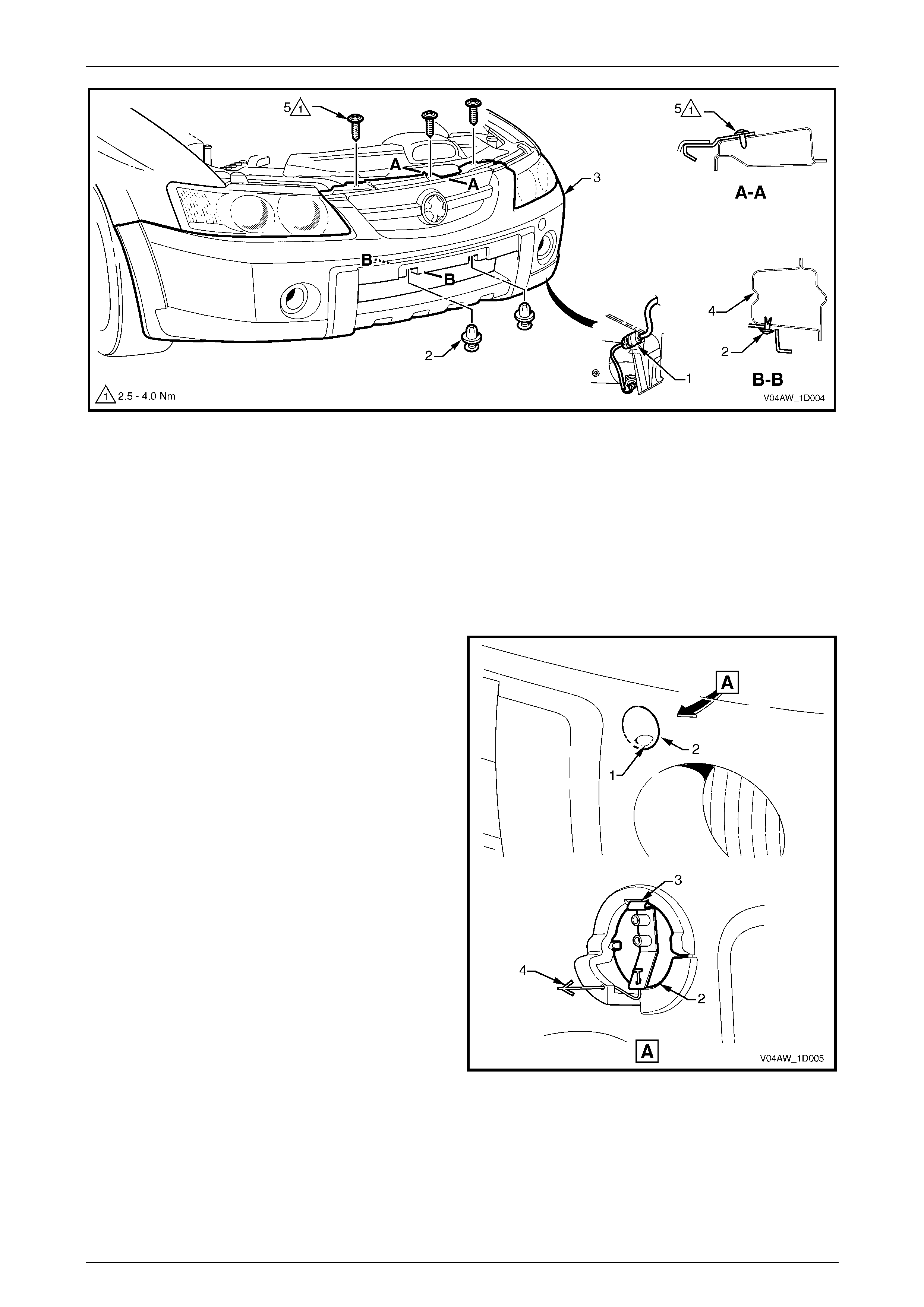
a Remove the screw (1), four places, attaching the front bumper fasc ia assembly (2) to the bumper fascia guide
assembly (3) and wheelhouse liner (4), refer to Figure 1D – 5.
b Carefully unclip the front bumper fascia assembly from the guide assembly by grasping the upper end of the
bumper fascia and pulling away from the vehicle.
Figure 1D – 5
3 If fitted, disconnect the front fog lamp wiring connector (1), one place each side, refer to Figure 1D – 6.
4 Remove the two retainers (2) from the recesses (behind the licence plate), attaching the front bumper fascia
assembly (3) to the front bumper impact bar assembly (4).
5 Remove the three screws (5) attaching the front bumper fascia assembly to the front upper panel.
Bumper Ba r s Page 1D–7
Page 1D–7
Figure 1D – 6
6 With the aid of an assistant remove the front bumper fascia assembly and store in a safe place.
Disassemble
1 As required remove the radiator grille assembly, refer to Se ction 1C Radiator Grille.
Recovery Point Cover
Remove
1 Press firmly on the indent (1) in the recovery point
cover (2) to release the cover retainer (3).
2 Push the end of the tether (4) together and through the
hole to remove the cover from the front bumper fascia.
Figure 1D – 7
Reinstall
1 Fit the cover into position, ensuring it is correctly oriented and clip onto the front bumper fascia assembly.
Bumper Ba r s Page 1D–8
Page 1D–8
Front Fog Lamp Opening Cover, Low Level
Remove
1 Depress the two retaining tabs (1) securing the
cover (2) to the front bumper fascia assembly.
2 Withdraw the cover from the recess to the front of the
bumper fascia. If required push out from the rear of the
bumper fascia.
Figure 1D – 8
Reinstall
1 Fit the cover into position and ensure that the retaining tabs are seated correctly.
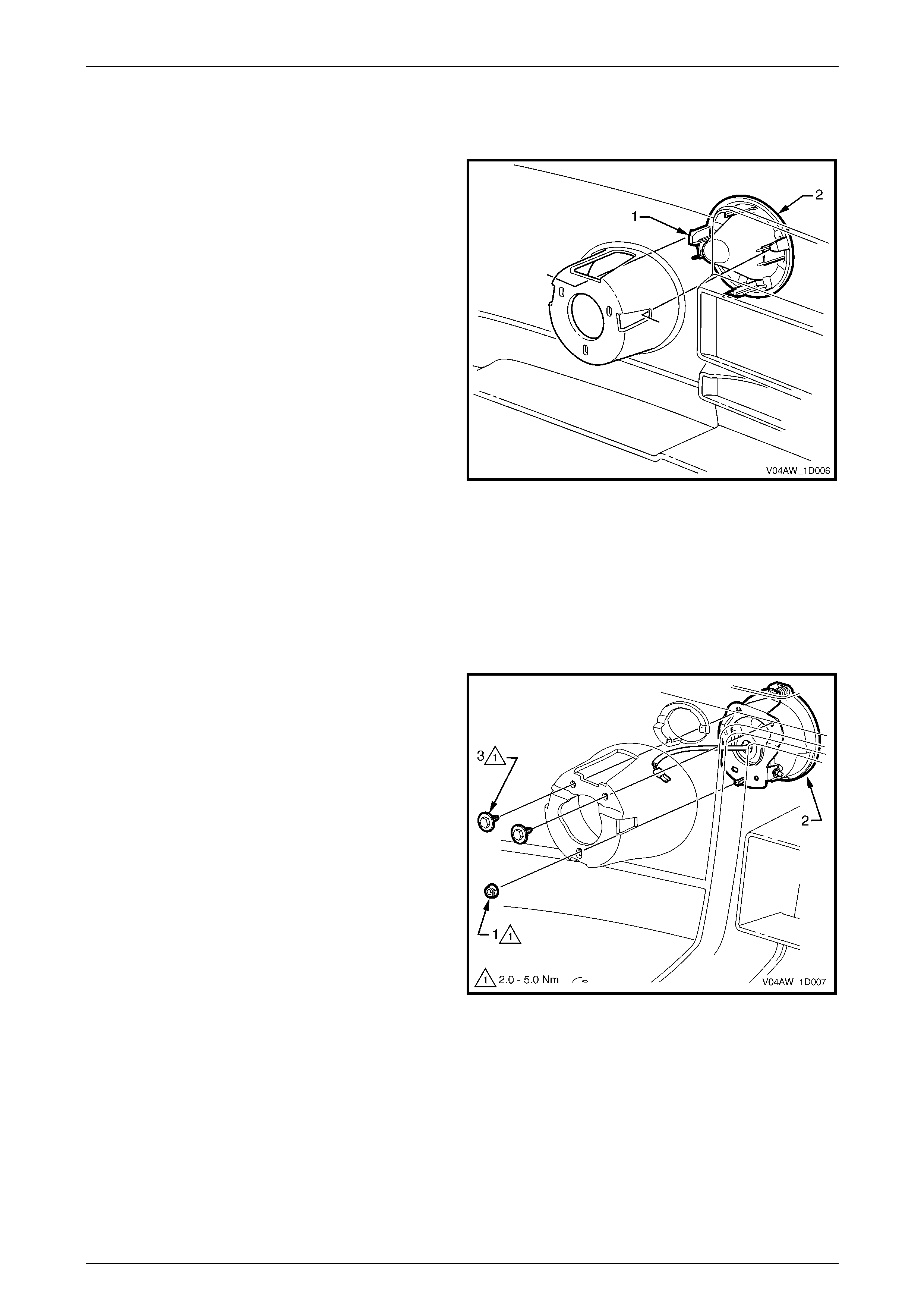
Front Fog Lamp Assembly, High Level
Remove
1 Remove the nut (1) attaching the front fog lamp
assembly (2) to the front bumper fascia assembly.
2 Remove the two screws (3) attaching the lamp
assembly to the bumper fascia.
3 Withdraw the lamp assembly and wiring connector
from the recess the front of the bumper fascia.
NOTE
For further service of the front fog lamp
assembly refer to Section 12B, 2.7 Front Fog
Lamp Assembly in the MY 2003 VY and
V2 Series Service information.
Figure 1D – 9
Bumper Ba r s Page 1D–9
Page 1D–9
Reinstall
NOTE
Following installation of the front bumper
fascia assembly, aim the fog lamps, refer to
Section 12B, 2.1 Headlamp and Fog Lamp
Aiming, in the MY 2003 VY and V2 Series
Service Information.
Reinstallation of the front fog lamp assembly is the reverse of the removal procedure, noting the following.
1 Tighten the fasteners to the correct torque specification.
Front fog lamp assembly attaching nut
torque specific atio n ....................................2.0 – 5.0 Nm
Front fog lamp assembly attaching screw
torque specific atio n ....................................2.0 – 5.0 Nm
Front Bumper Fascia Insert
Remove
1 From the rear of the front bumper fascia, lift the
tab (1), nine places, attaching the front bumper fascia
insert (2) to the front bumper fascia (3).
2 Remove the insert from the front bumper fascia
assembly.
Figure 1D – 10
Reinstall
1 Reinstall the insert to the front bumper fascia ensuring that all the tabs fit in the corresponding slots.
2 Fold the tabs over to secure the insert to the front bumper fascia.

Bumper Ba r s Page 1D–10
Page 1D–10
Reinstall
1 Refinish the front bumper fascia assembly, refer to Section 1D, 2.1 Paint Systems in the MY 2003 VY and V2
Series Service Inform ation.
2 With the aid of an assistant, fit the front bumper fascia as sembly onto the vehicle.
3 Start the three screws (5) attaching the front bumper fascia to the front upper panel, refer to Figure 1D – 6.
4 Install the two retainers (2) in the recesses (behind the licence plate).
5 Reconnect the fog lamp wiring connectors (1) if fitted.
6 Align the side of the front bumper fascia assembly to the fender, clip the front bumper fascia into the guide
assembly and install the screw (4), two places, refer to Figure 1D – 5. Repeat for the opposite side.
7 Install the screw (1), three places, attaching each side of the fascia to the front wheelhouse liner (3).
8 As required reinstall the front bumper fascia undertray, refer to 2.2 Front Bumper Fascia Undertray.
9 Tighten the fasteners to the correct torque specification.
Front bumper fascia assembly to
front wheelhouse liner screw
torque specific atio n ....................................1.0 – 3.0 Nm
Front bumper fascia assembly to front
bumper fascia guide assembly screw
torque specific atio n ....................................1.0 – 3.0 Nm
Front bumper fascia assembly to
front upper panel screw
torque specific atio n ....................................2.5 – 4.0 Nm
Bumper Ba r s Page 1D–11
Page 1D–11
2.4 Front Bumper Fascia Guide Assembly
LT Section No. – XX-XXX
Remove
1 Remove the front bumper fascia assembly, refer to 2.3 Front Bumper Fascia Assembly.
NOTE
It is possible to remove one side of the front
bumper fascia and carefully move it out to gain
access to the front bumper fascia guide
assembly.
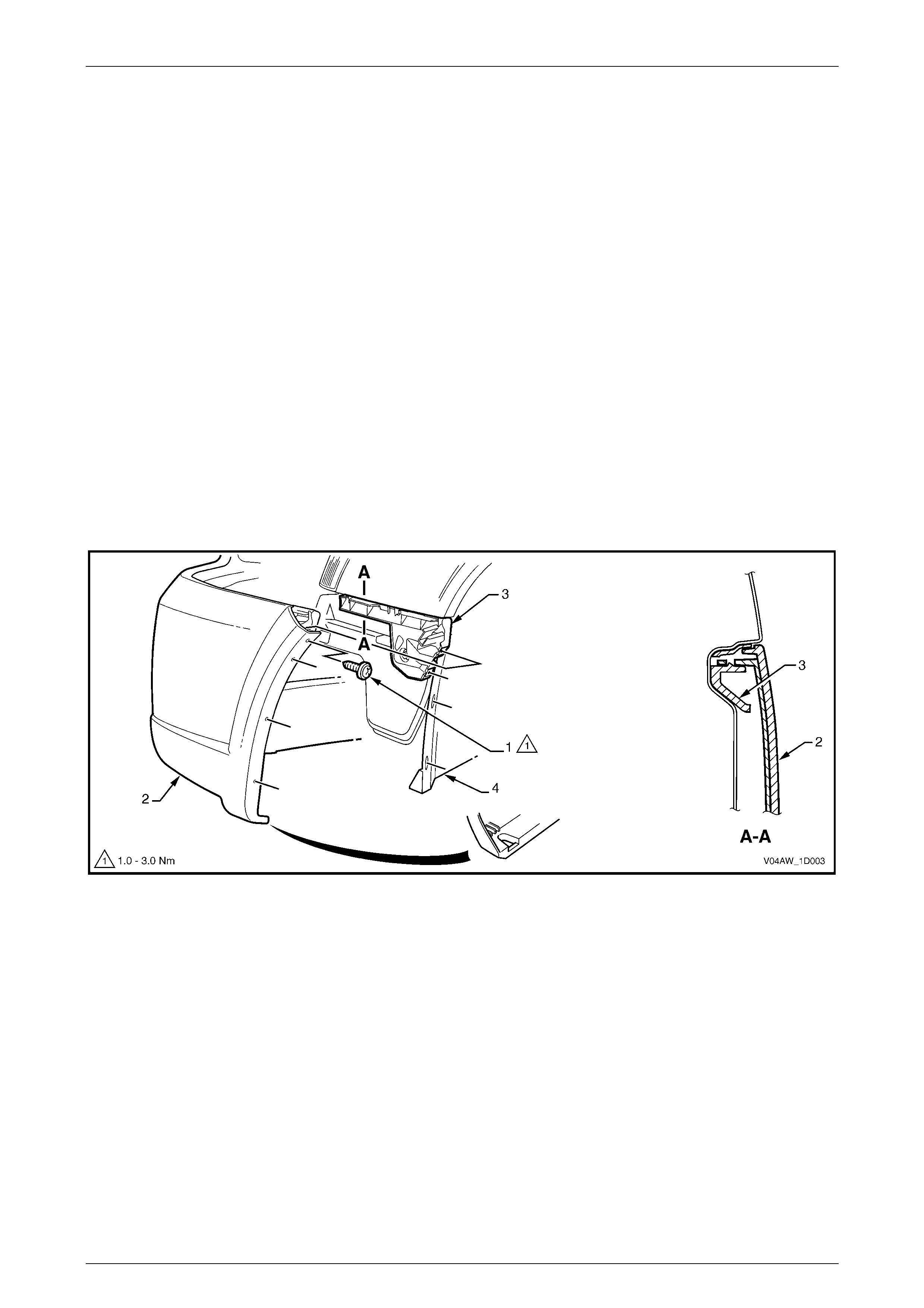
2 Using a fine flat-blade screwdriver, lever and hold the
tab (1) outwards.
3 Slide the front bumper fascia guide as sembly (2)
forward and out to detach it from the fender.
Figure 1D – 11
Reinstall
1 Align the guide assembly with the slots in the fender and while pushing in slightly, slide the guide rearwards until it
‘clicks’ into place.
2 Reinstall the bumper fascia as required, refer to 2.3 Front Bumper Fa scia Assembly.
Bumper Ba r s Page 1D–12
Page 1D–12
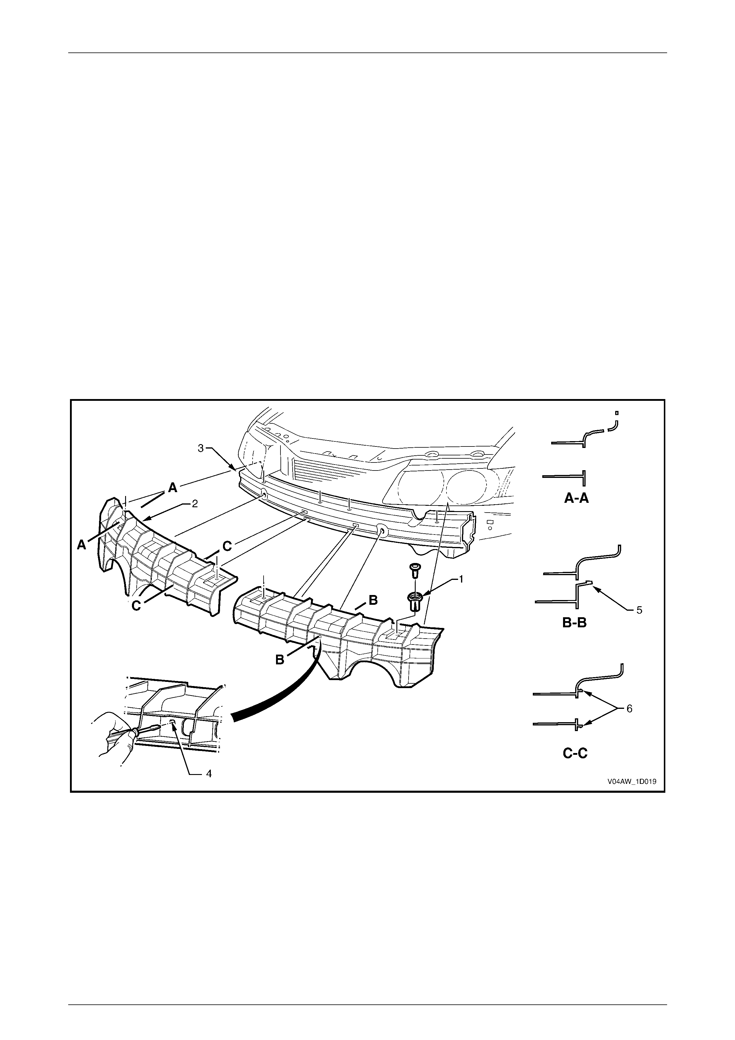
2.5 Front Bumper Fascia Support
LT Section No. – XX-XXX
Remove
NOTE
Each bumper fascia support is removed
separately, with the removal procedure for both
bumper fascia supports being identical.
1 Remove the front bumper fascia assembly, refer to 2.3 Front Bumper Fascia Assembly.
2 Prise the centre pin and remove the retainer (1), in two places, securing the front bumper fascia support (2) to the
front bumper impact bar (3), refer to Figure 1D – 12.
3 Insert a flat blade screwdriver into the opening (4) in the bumper fascia support and depress the tab (5). Whilst
depressing the tab, slightly rotate the bottom of the bumper fascia support upwards to release the remaining two
retaining clips (6).
4 Remove the bumper fascia support.
Figure 1D – 12
Reinstall
1 Align the three bumper fa scia support retaining clips (5 and 6) with the front bumper impact bar. Push the bumper
fascia support into the front bumper to engage the retaining clips, refer to Figure 1D – 12.
2 Install the bumper fascia support retainers (1).
3 Tighten the fasteners to the correct torque specification.
4 Reinstall the front bumper fascia assembly as required, refer to 2.3 Front Bumper Fascia Assembly.
Bumper Ba r s Page 1D–13
Page 1D–13
2.6 Rear Bumper Fascia Assembly
LT Section No. – 07-525
Remove
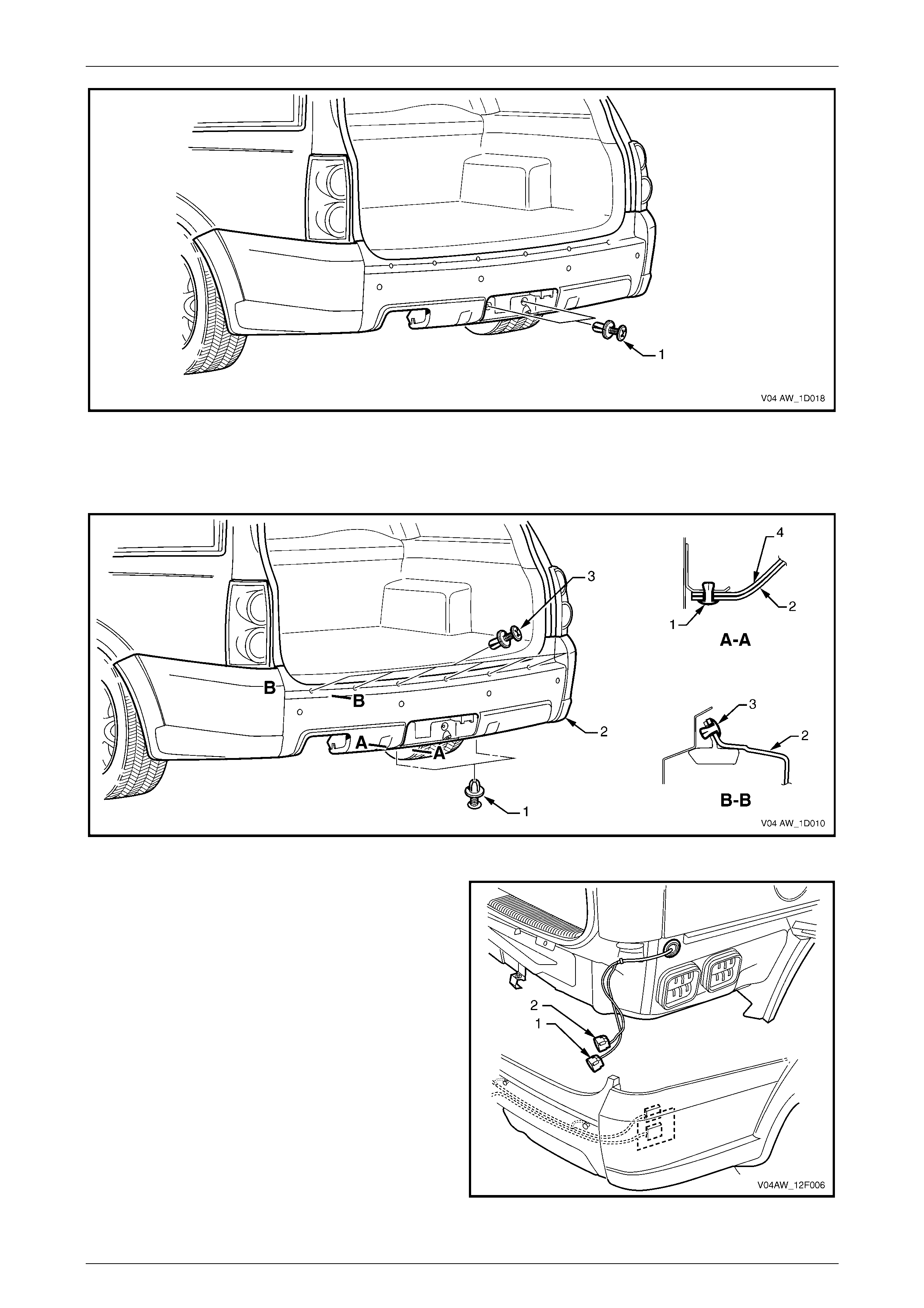
1 Rotate the retainer (1), two places, ninety degrees to
release the towbar opening cover (2) from the rear
bumper fascia assembly (3).
2 Remove the co ver from the bumper fascia.
3 Remove the screw (1), two places each side, attaching
the rear bumper fascia assembly (2) to the rear
wheelhouse liner (3), refer to Figure 1D – 14.
4 Remove the screw (4), two places each side, attaching
the rear bumper fascia assembly to the rear bumper
fascia guide assembly (5).
5 Disconnect the pin (6) from the liner.
6 Carefully unclip the bumper fascia assembly from the
guide assembly by grasping the upper end of the
bumper fascia assembly and pulling away from the
vehicle.
Figure 1D – 13
Figure 1D – 14
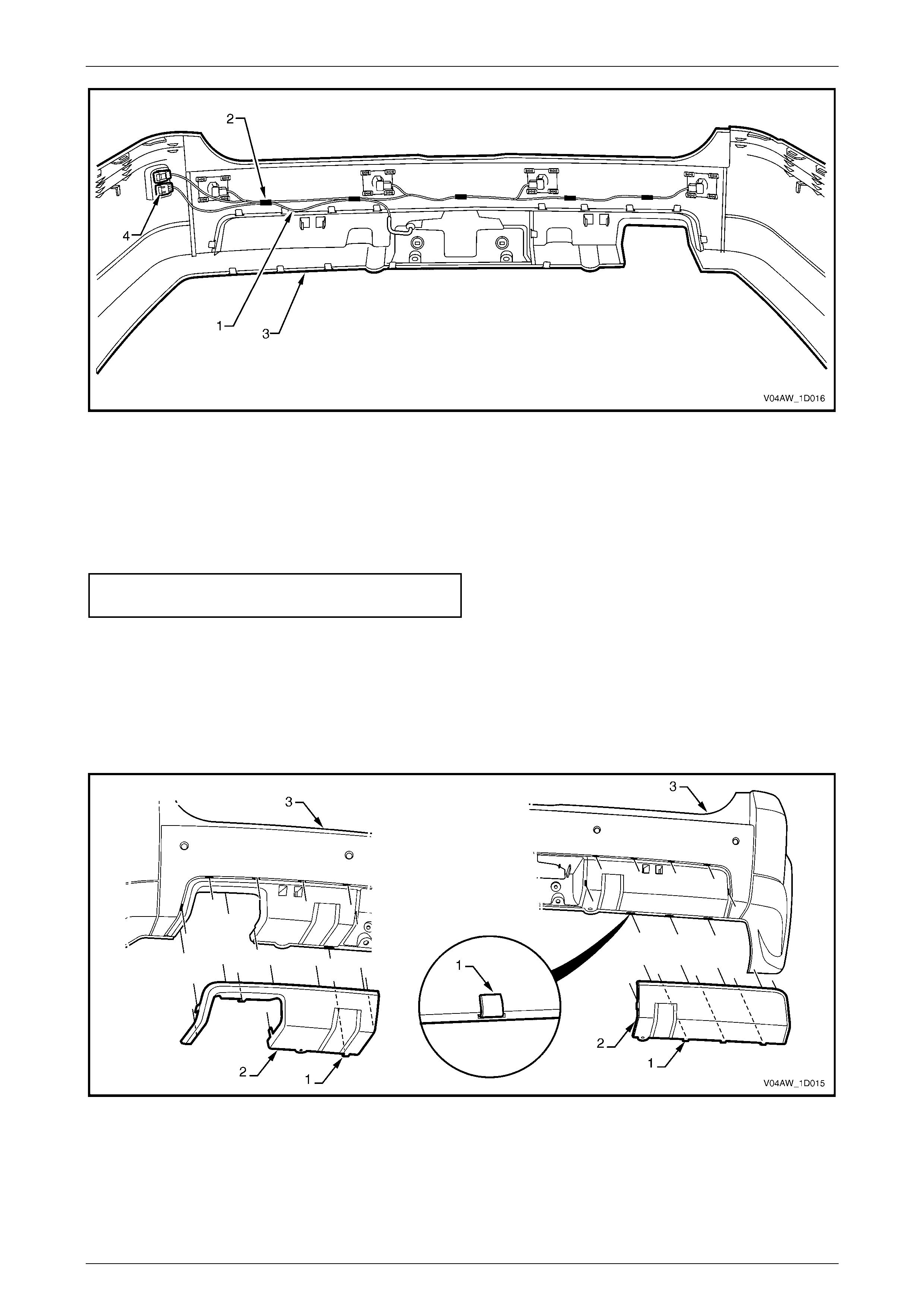
7 Remove the retainer (1) from either side of the towbar opening, refer to Figure 1D – 15.
Bumper Ba r s Page 1D–14
Page 1D–14
Figure 1D – 15
8 Remove the two retainers (1) from below the rear bumper fascia assembly (2), refer to Figure 1D – 16.
9 Remove the six retainers (3) from across the liftgate opening.
Figure 1D – 16
10 With the aid of an assistant remove the bumper from
the vehicle far enough to access the wiring
connectors.
11 Disconnect the towbar wiring connector (1).
12 Disconnect the reverse parking aid wiring
connector (2).
13 Remove the rear bumper fascia assembly, sliding it
rearward.
Figure 1D – 17

Bumper Ba r s Page 1D–15
Page 1D–15
Disassemble
Rear Bumper Fascia Filler
Remove
1 Spread the tangs (1) and unclip the rear bumper fascia filler (2) from the rear bumper fascia (3).
Figure 1D – 18
Reinstall
1 Clip the rear bumper fascia filler back onto the rear bumper fascia.
Reverse Parking Aid Components
Remove
Replacement sensor assemblies are supplied
pre-painted in the vehicle's body colour. Do
not apply further paint to the sensor, as it will
have a detrimental effect on the sensor's
operation.
1 Disconnect the rear object sensor connector (1) from
the rear object sensor assembly (2).
2 Lift the top and bottom tabs on the rear object sensor
housing (3) and remove the rear object sensor
assembly and the rear object sensor ring (4) from the
rear object sensor housing.
3 If required, remove the rear object sensor ring from the
rear object sensor.
4 Remove the rear object sensor housing from the rear
bumper fascia by carefully prising the four retainers (5)
with a flat-blade screwdriver.
5 Remove the rear object sensor harness (1) by prising
the clips (2), five places, from the bumper fascia (3),
refer to Figure 1D – 20.
6 Unclip the rear object sensor harnes s conn ect or (4)
from the bumper fascia.
Figure 1D – 19

Bumper Ba r s Page 1D–16
Page 1D–16
Figure 1D – 20
Reinstall
Ensure that the rear object sensor ring is
correctly seated on the sensor and that the
sensor assembly is securely located in the
housing. The sensor ring prevents vibrations
from the sensor being transferred to the
surrounding components. Incorrect fitment
will result in a change to the sensor
characteristics.
Reinstallation of the rear object sensor assembly is the reverse of the removal procedure, noting the following.
1 Ensure that the sensors are correctly installed in the housing with the connector side facing to the centreline of the
vehicle.
2 Attach the wiring harness to the rear bumper fascia by pressing each clip onto the corresponding rib.
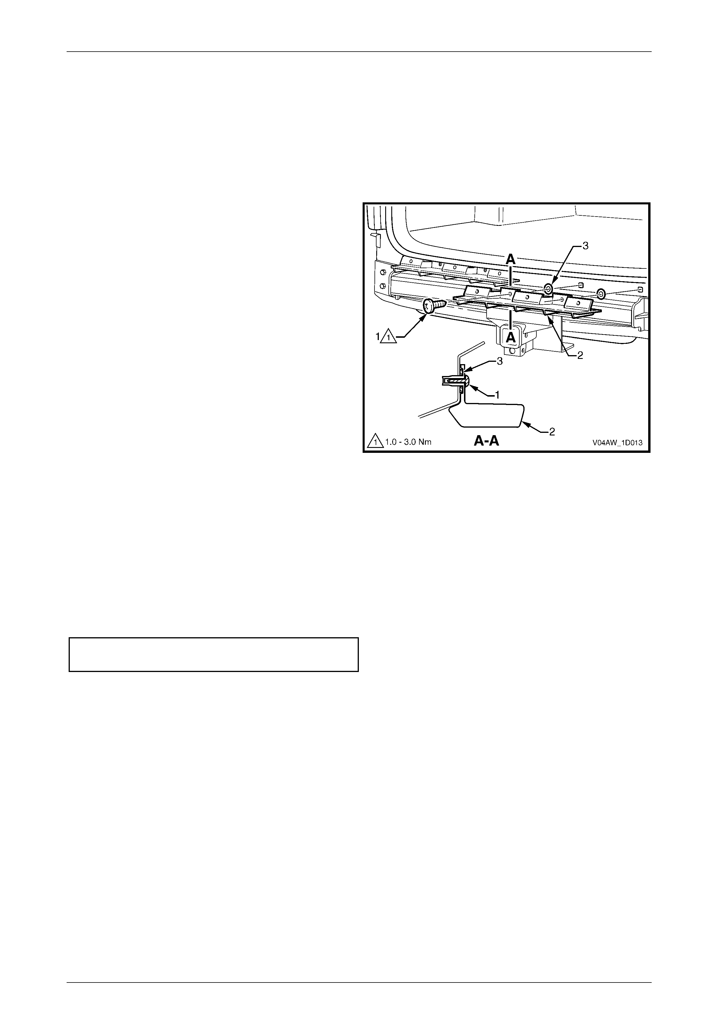
Trailer Wiring Harness
1 Remove the sc rew (1), two places, attaching the trailer
plug to the rear bumper fascia.
2 Remove the trailer plug from the fascia.
3 Remove the trailer wiring harness (1) by prising the
clips (2), five places, from the bumper fascia (3), refer
to Figure 1D – 22.
4 Unclip the trailer wiring harness connector (4) from the
bumper fascia.
5 Pull the trailer plug through the rear bumper fascia and
remove the harness.
Figure 1D – 21
Bumper Ba r s Page 1D–17
Page 1D–17
Figure 1D – 22
Reinstall
Reinstallation of the trailer wiring harness is the reverse of the removal procedure, noting the following.
1 Attach the trailer wiring harness to the rear bumper fascia by pressing each clip onto the corresponding rib.
2 Tighten the fasteners to the correct torque specification.
Trailer plug attaching screw torque
specification................................................1.0 – 3.0 Nm
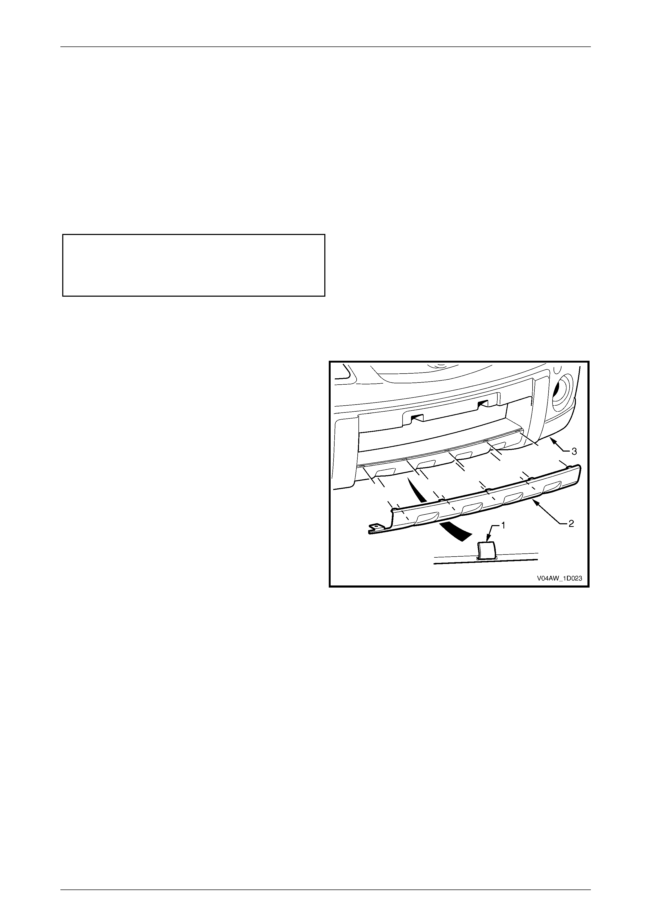
Rear Bumper Fascia Insert
Remove
1 Lift the tab (1), ten places on the left-hand side or nine places on the right-hand side, attach ing the rear bumper
fascia insert (2) to the rear bumper fascia (3).
2 Remove the insert from the rear bumper fascia.
Figure 1D – 23
Reinstall
1 Reinstall the insert to the rear bumper fascia ensuring that all the tabs fit in the corresponding slots.
2 Fold the tabs over to secure the insert to the rear bumper fascia.

Bumper Ba r s Page 1D–18
Page 1D–18
Reinstall
1 Refinish the rear bumper fascia assembly, refer to Section 1D, 2.1 Paint Systems in the MY 2003 VY and V2
Series Service Inform ation.
2 With the aid of an assistant, install the rear bumper fascia assembly, ensuring th at it is seated correctly.
3 Install the six retainers (3) around the li ftgate opening, refer to Figure 1D – 16.
4 Insert the two retainers (1) from below the bumper fascia assembly.
5 Align the side of the bumper fascia assembly to the quarter panel and clip the rear bumper fascia assembly into the
guide assembly (4), refer to Figure 1D – 14. Repeat for the opposite side.
6 Install the four screws on each side, attaching the rear bumper fasc ia assembly to the guide assembly and rear
wheelhouse liner.
7 Clip the towbar opening cover in place ensuring the retaining tabs are seated correctly and install the two retainers.
8 Tighten the fasteners to the correct torque specification.
Rear bumper fascia assembly to rear
wheelhouse liner attaching screw torque
specification................................................1.0 – 3.0 Nm
Rear bumper fascia assembly to rear
bumper fascia guide assembly attaching
screw torque specification.......................... 1.0 – 3.0 Nm
Bumper Ba r s Page 1D–19
Page 1D–19
2.7 Rear Bumper Fascia Guide Assembly
LT Section No. – XX-XXX
Remove
1 Remove the rear bumper fascia assembly, refer to 2.6 Rear Bumper Fascia Assembly.
NOTE
It may be possible to remove one side of the
bumper fascia and carefully move it out far
enough to gain access to the guide assembly.
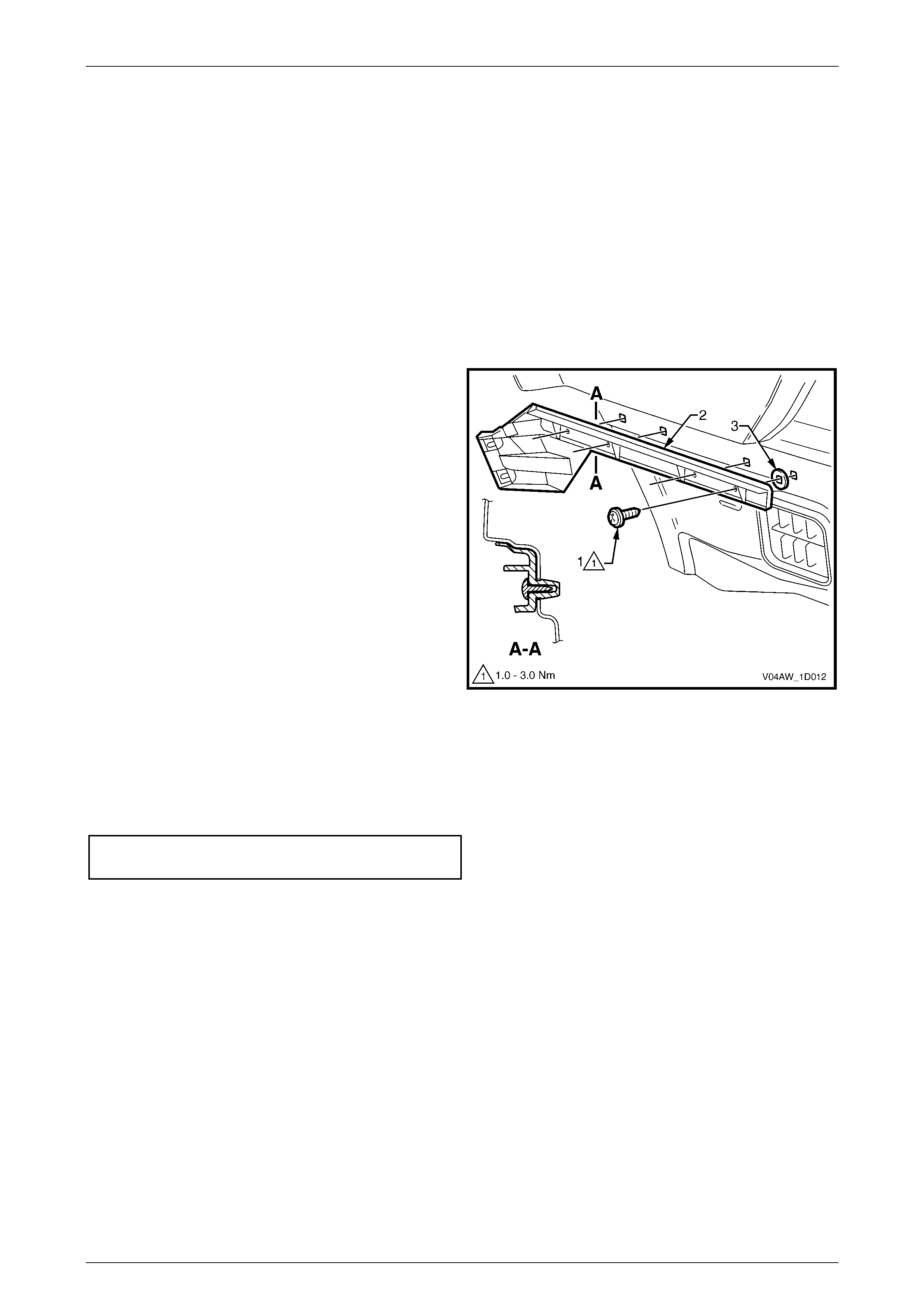
2 Remove the four screws (1) attaching the rear bu mper
fascia guide assembly (2).
3 Prise the guide assembly out to detach it from the
vehicle.
NOTE
Ensure the seal (3), four places, is removed wi th
the guide assembly.
Figure 1D – 24
Reinstall
Reinstallation of the rear bumper fascia guide assembly is the reverse of the removal procedure, noting the following.
1 Tighten the sc rews to the correct torque specification.
Rear bumper fascia guide assembly
attaching screw torque specification........... 1.0 – 3.0 Nm
Bumper Ba r s Page 1D–20
Page 1D–20
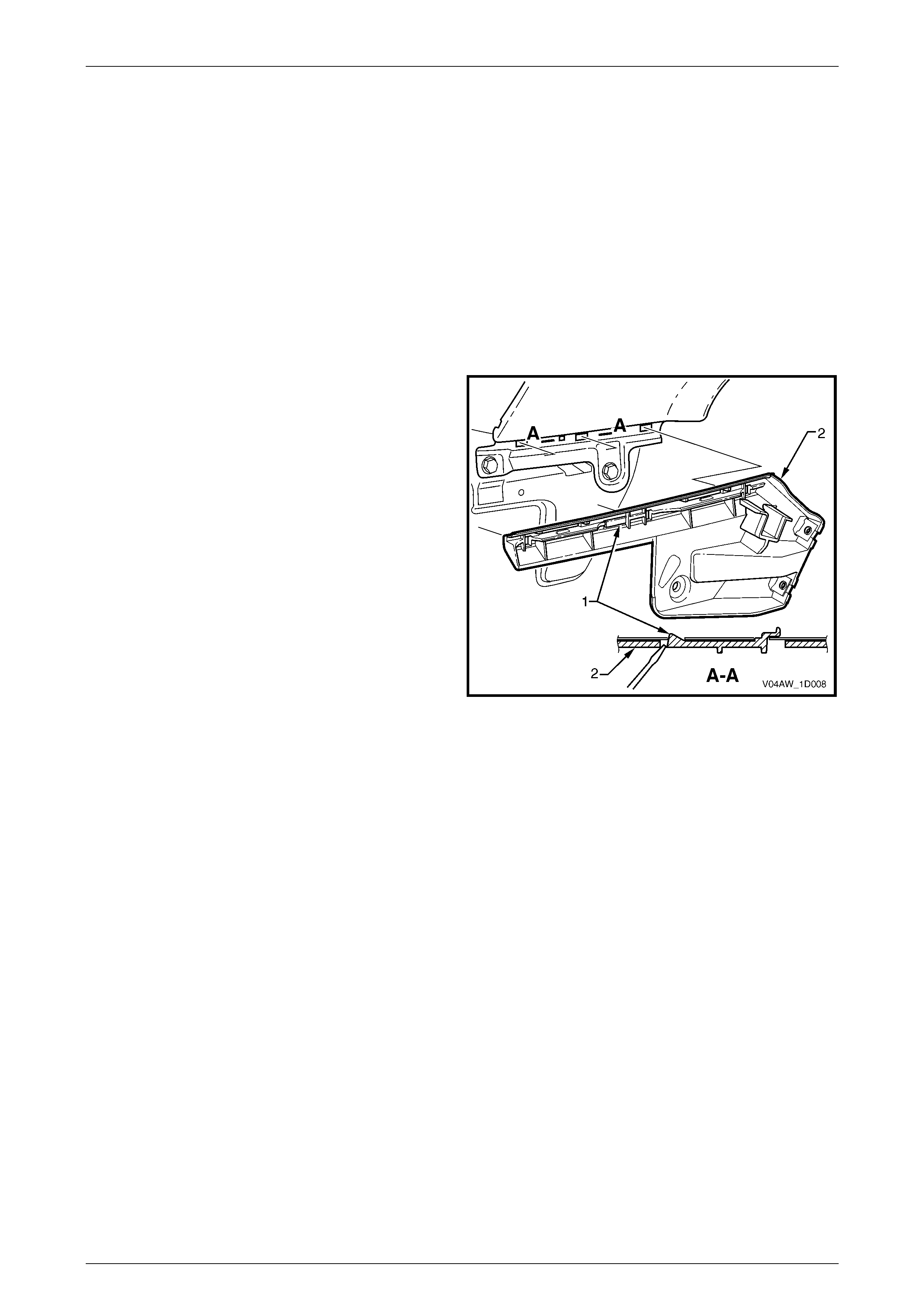
2.8 Rear Bumper Fascia Upper Support
LT Section No. – XX-XXX
Remove
1 Remove the rear bumper fascia assembly, refer to 2.6 Rear Bumper Fascia Assembly.
2 Remove the sc rew (1), two places, attaching the rear
bumper fascia support (2) to the vehicle.
3 Prise the support from the vehicle ensuring the
seals (3) remain with the support.
4 Repeat for the opposite support as required.
Figure 1D – 25
Reinstall
Reinstallation of the rear bumper fascia upper support is the reverse of the removal proced ure, noting the following.
1 Tighten the sc rews to the correct torque specification.
NOTE
Ensure the seals are correctly fitted to the
support prior to installation.
Rear bumper fascia upper support
attaching screw torque specification........... 1.0 – 3.0 Nm
Bumper Ba r s Page 1D–21
Page 1D–21
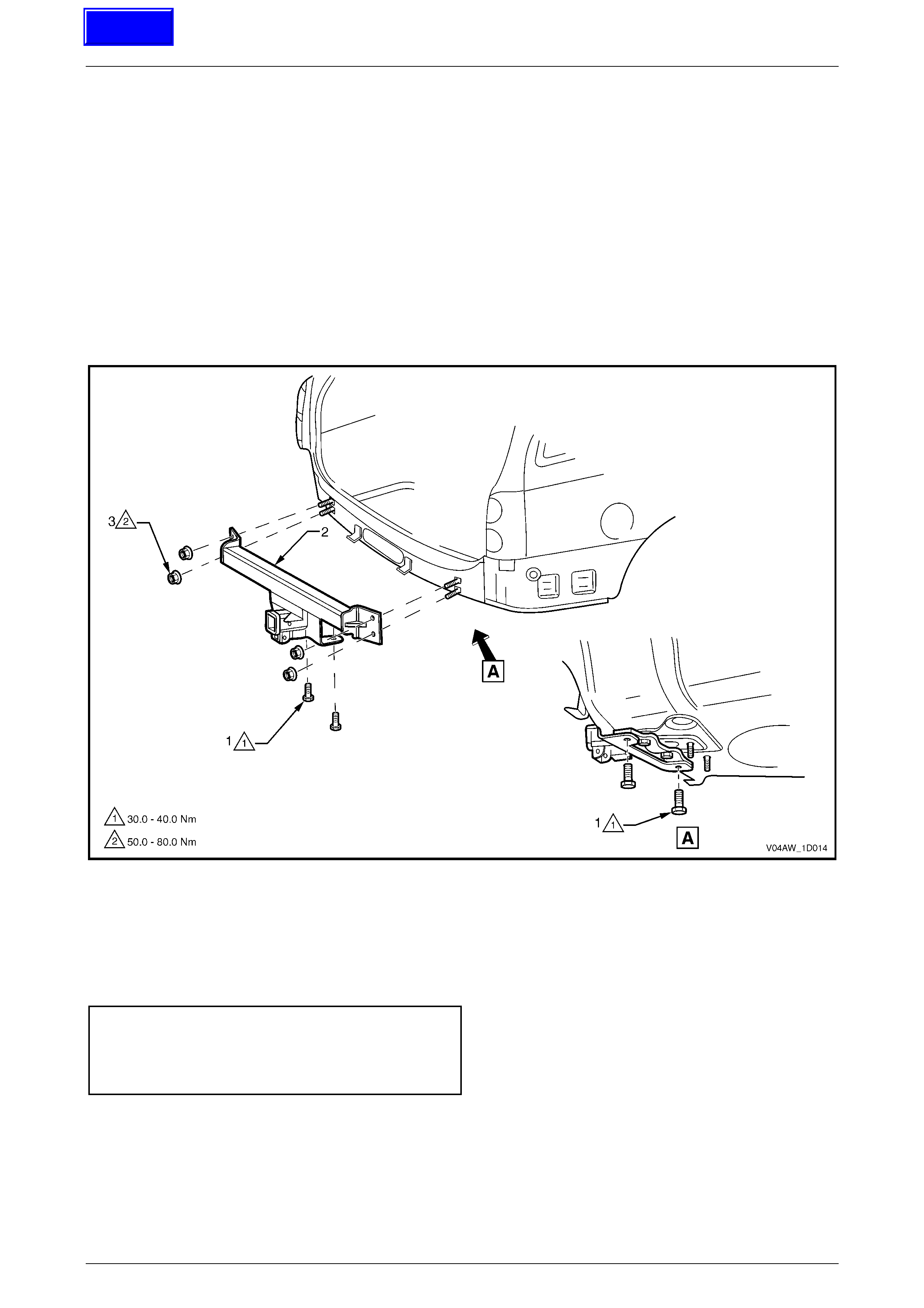
2.9 Towbar Assembly
LT Section No. – XX-XXX
Remove
1 Remove the rear bumper fascia assembly, refer to 2.6 Rear Bumper Fascia Assembly.
2 Remove the rear bumper fascia upper support, refer to 2.8 Rear Bumper Fascia Upper Support.
3 Remove the screw (1), two places, attaching the towbar assembly (2).
4 Remove the nuts (3), two places each side, attaching the towbar assembly to the vehicle.
5 Remove the towbar assembly.
Figure 1D – 26
Reinstall
Reinstallation of the towbar assembly is the reverse of the removal procedure noting the following.
1 Tighten the sc rews to the correct torque specification.
Towbar assembly attaching screw
torque specification ................................ 30.0 – 40.0 Nm
Towbar assembly attaching nut
torque specification ................................ 50.0 – 80.0 Nm
Techline

Bumper Ba r s Page 1D–22
Page 1D–22
3 Torque Wrench Specifications
Front Bumper Fascia Undertray to Crossmember
Attaching Screw ............................................................................5.5 – 8.5 Nm
Front Bumper Fascia Undertray to Bumper Fascia
Attaching Hex-Head Screw ...........................................................5.5 – 8.5 Nm
Front Bumper Fascia Undertray to Bumper Fascia
Attaching Screw ............................................................................1.0 – 3.0 Nm
Front Fog Lamp Assembly Attaching Nut .....................................2.0 – 5.0 Nm
Front Fog Lamp Assembly Attaching Screw .................................2.0 – 5.0 Nm
Front Bumper Fascia Assembly to Front Wheelhouse
Liner Attaching Screw ...................................................................1.0 – 3.0 Nm
Front Bumper Fascia Assembly to Front Bumper
Fascia Guide Assembly Attaching Screw .....................................1.0 – 3.0 Nm
Front Bumper Fascia Assembly to Front Upper Panel
Attaching Screw ............................................................................2.5 – 4.0 Nm
Trailer Plug Attaching Screw .........................................................1.0 – 3.0 Nm
Rear Bumper Fascia Assembly to Rear Wheelhouse
Liner Attaching Screw ...................................................................1.0 – 3.0 Nm
Rear Bumper Fascia Assembly to Rear Bumper
Fascia Guide Assembly Attaching Screw .....................................1.0 – 3.0 Nm
Rear Bumper Fascia Assembly to Rear Wheelhouse
Liner Attaching Screw ...................................................................1.0 – 3.0 Nm
Rear Bumper Fascia Assembly to Rear Bumper
Fascia Guide Assembly Attaching Screw .....................................1.0 – 3.0 Nm
Rear Bumper Fascia Upper Support Attaching Screw ..................1.0 – 3.0 Nm
Towbar Assembly Attaching Screw............................................30.0 – 40.0 Nm
Towbar Assembly Attaching Nut ...............................................50.0 – 80.0 Nm