Sunroof – Online Page 1F2–1
Page 1F2–1
Section 1F2
Sunroof – Online
ATTENTION
Before performing any Service Operation or other procedure described in this Section, refer to Section 00
Warnings, Cautions and Notes for correct workshop practices with regard to safety and/or property damage.
1 General Information............................................................................................................................... 2
1.1 Sunroof Assembly..................................................................................................................................................2
Pre-programmed Functions..................................................................................................................................2
Variable Tilt Position...........................................................................................................................................2
Sunroof Power harness.........................................................................................................................................2
Rear Drain Tube......................................................................................................................................................2
2 Service Operations................................................................................................................................3
2.1 Sunroof Power Harness.........................................................................................................................................3
Remove ...................................................................................................................................................................3
Reinstall ..................................................................................................................................................................4
2.2 Rear Drain Tube......................................................................................................................................................5
Remove ...................................................................................................................................................................5
Reinstall ..................................................................................................................................................................7
3 Diagnosis................................................................................................................................................ 8
3.1 Fault Diagnosis Charts..........................................................................................................................................8
Introduction ............................................................................................................................................................8
Prerequisites...........................................................................................................................................................8
Safety Requirements..........................................................................................................................................8
Equipment ..........................................................................................................................................................8
Testing Procedures.............................................................................................................................................9
Functional Test.......................................................................................................................................................9
Test Description..................................................................................................................................................9
Electrical Test.......................................................................................................................................................11
Test Description................................................................................................................................................11
Sunroof Switch and Sunroof Control Harness Test..........................................................................................15
Repair Advice For Mechanical Failures..............................................................................................................15
Repair Advice For Electrical Failures.................................................................................................................16
Repair Advice For Rattling Noises......................................................................................................................16
Repair Advice For Wind Noises..........................................................................................................................16
Repair Advice For Water Leaks...........................................................................................................................16
3.2 Wiring Diagram – Sunroof...................................................................................................................................17
3.3 Connector Diagrams – Sunroof ..........................................................................................................................18
4 Torque Wrench Specifications........................................................................................................... 19

Sunroof – Online Page 1F2–2
Page 1F2–2
1 General Information
With the following exceptions, MY 2004 VY AWD Wagon online sunroof information carries over from MY 2003 VY
Series vehicles:
• variable tilt position of the glass panel,
• sunroof power harness,
• rear drain tube,
• fault diagnosis charts ,
• wiring diagram, and
• connector diagrams.
For information not contained within this Section, refer to Section 1F2 Sunroof in the MY 2003 VY and V2 Series Service
Information.
NOTE
W hen r emo ving the hea dli nin g and int eri or t rim to
access the sunroof components, refer to
Section 1A8 Headlining and Interior Trim.
1.1 Sunroof Assembly
Pre-programmed Functions
With the exception of the variable tilt position, the pre-programmed functions are identical to the MY 2003 VY Series
vehicles. Refer to Section 1F2, 1. General Description, in the MY 2003 VY and V2 Series Service Information.
Variable Tilt Position
The sunroof can be lowered from maximum tilt opening in three intermediate tilt positions. Press and hold the sunroof
button ! until the glass panel reaches the next tilt position. Alternatively hold the button pressed and then release it at
the desired glass panel tilt position.
Sunroof Power harness
The sunroof power harness is routed along the roof panel from the sunroof control unit (SCU) to the body harness at the
rear of the vehicle. The sunroof power harness is taped to three retaining clips attached to the right-hand side quarter
panel inner assembly; the ground wire is also attached to the right-hand side quarter panel inner assembly.
Rear Drain Tube
The sunroof rear drain tubes are routed on either side of the vehicle along the roof panel from the sunroof rear drain
outlets to grommets at the rear of the rear quarter panels. Each rear drain tube is secured to the quarter panel inner
assembly by three retaining clips.

Sunroof – Online Page 1F2–3
Page 1F2–3
2 Service Operations
2.1 Sunroof Power Harness
LT Section –
Remove
1 Remove the sunroof circuit breaker F3 from the passenger compartment fuse and relay panel assembly, refer to
Section 12O Fuses, Relays and Wiring Harnesses.
2 Remove the headlining, refer to Section 1A8 Headlining and Interior Trim.
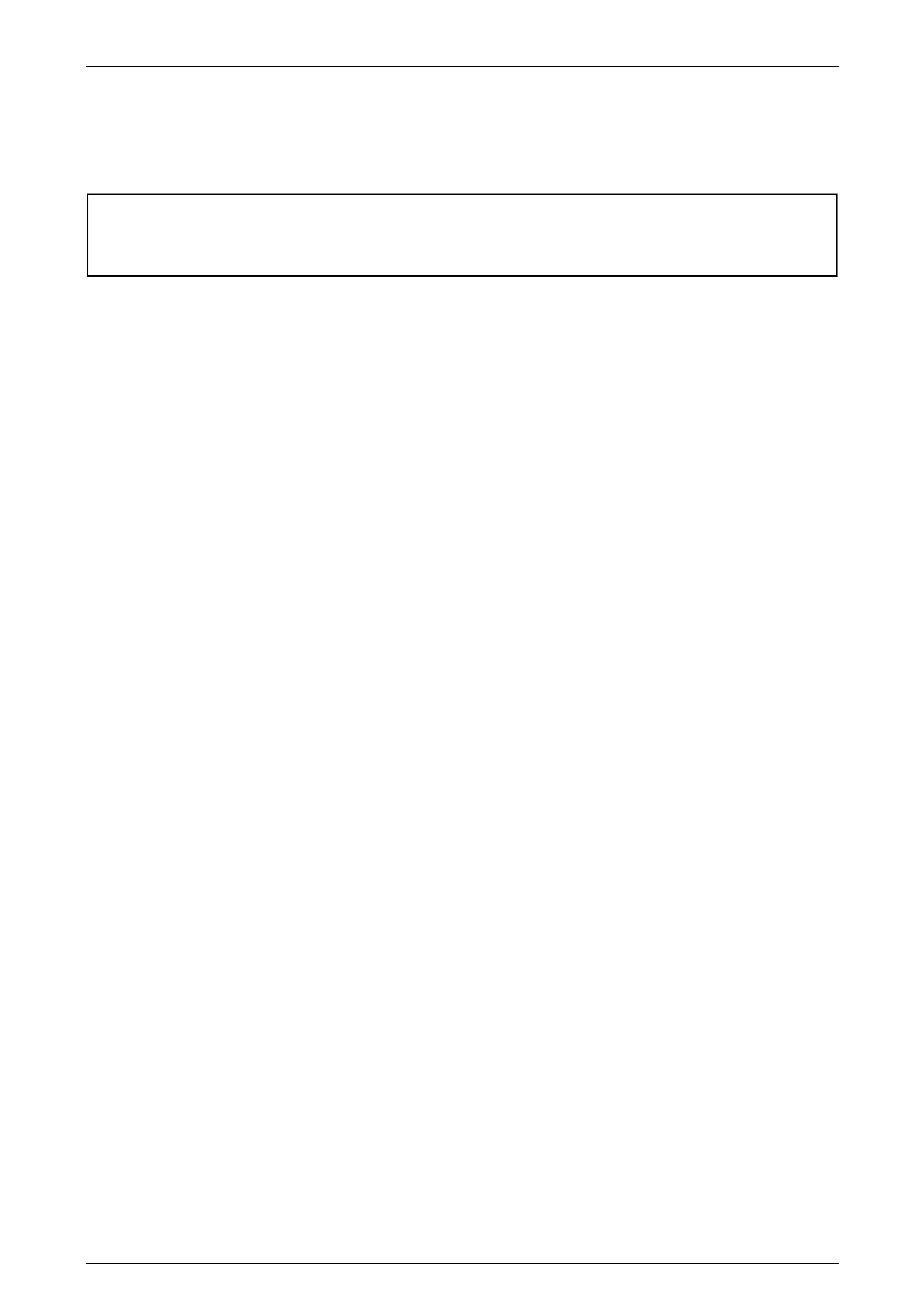
3 Disconnect the SCU connector A108 – X1 (1) from the SCU, refer to Figure 1F2 – 1.
4 Unclip the sunroof power harness (2) from the sunroof drive cable guides plastic support clip (3).
5 Remove the self-tapping screw (4) securing the ground wire (5) to the right-hand side quarter panel inner
assembly.
6 Disconnect the sunroof power harness connector X322 (6) from the vehicle body harness connector.
7 Remove the right-hand rear drain tube (7) from the three retaining clips (8).
8 Remove the sunroof power harness and the three attached retaining clips from the right-hand side quarter panel
inner assembly .
NOTE
Do not re-use the rear drain tube retaining clips,
as they are damaged when removed from the
quarter panel inner assembly.
9 If required, remove the right-hand rear drain tube from the sunroof assembly, refer to 2.2 Rear Drain Tube.
Sunroof – Online Page 1F2–4
Page 1F2–4
Figure 1F2 – 1
Legend
1 SCU Connect or A108 – X1
2 Sunroof Power Harness
3 Cable Guides Support Clip
4 Ground Connector Self-Tappi ng Screw
5 Power Harness Ground Connector
6 Power Harness Connector X322
7 Right-Hand Rear Drain Tube
8 Retaining Clips
Reinstall
Installation of the sunroof power harness is the reverse of the removal, noting the following:
1 Ensure that three new retaining clips are taped to the sunroof power harness at the correct locations before
installing to the right-hand side quarter panel inner assembly.
2 Ensure that the ground connectio n (5) is securely attached to the right-hand side quarter panel inner assembly.
Tighten the screw (4) to the specified torque, refer to Figure 1F2 – 1.
Sunroof power harness ground
screw torque specification.......................... 1.5 – 3.0 Nm

Sunroof – Online Page 1F2–5
Page 1F2–5
2.2 Rear Drain Tube
LT Section –
Remove
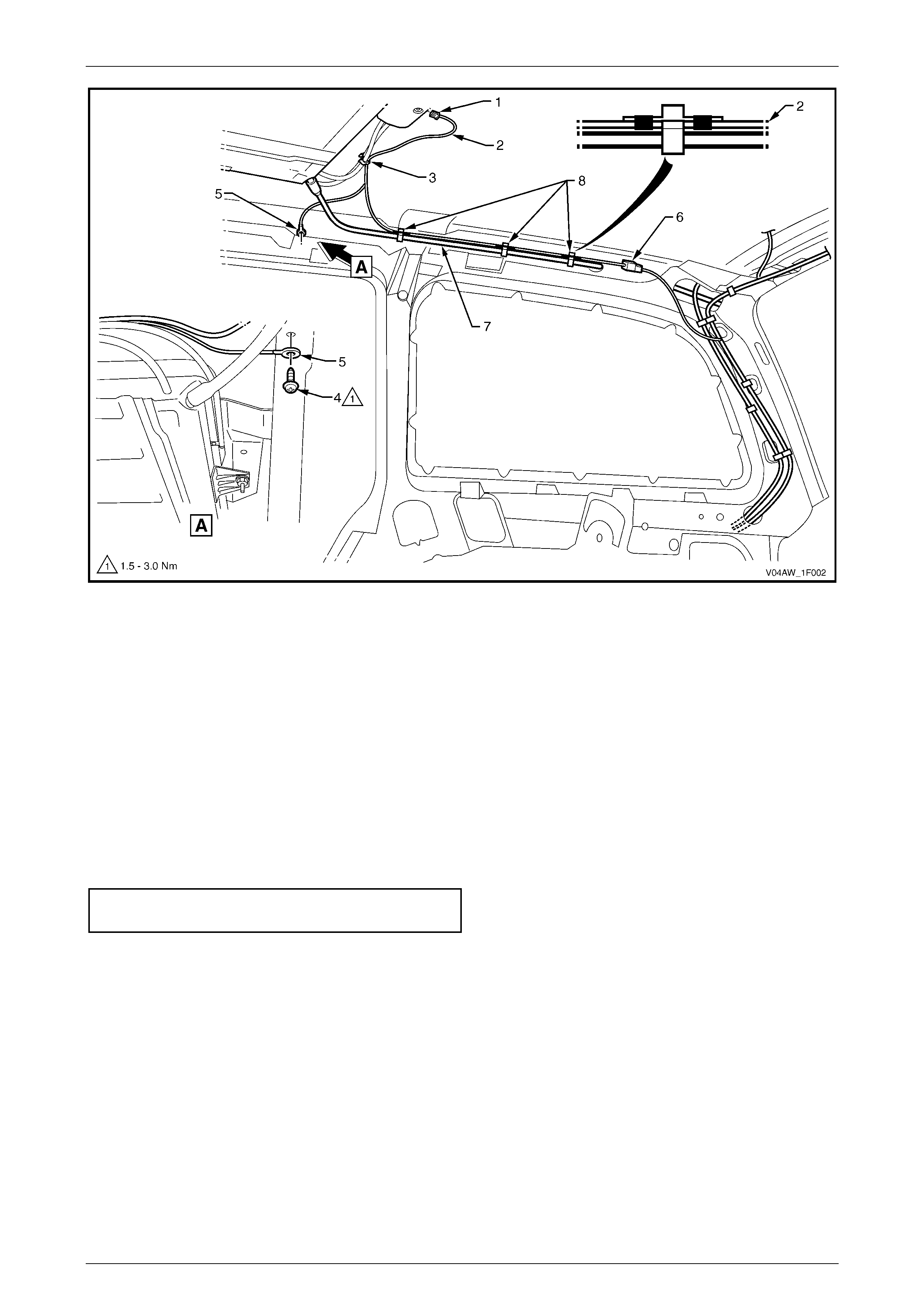
Refer to Figure 1F2 – 2 for the following:
1 Remove the sunroof circuit breaker F3 from the passenger compartment fuse and relay panel assembly, refer to
Section 12O Fuses, Relays and Wiring Harnesses.
2 Remove the headlining, refer to Section 1A8 Headlining and Interior Trim.
3 Note the rear drain tube retaining clip locations (three places), the entry point in the quarter panel inner assembly,
and general routeing of the rear drain tube (1) and sunroof power harness (2) (right-hand side only).
4 Unclip the rear drain tube from the retaining clips (3) on the quarter panel inner assembly.
5 Carefully pull the rear drain tube from the sunroof assembly rear drain tube outlet (4).
6 Pull the rear drain tube from the grommet (5).
NOTE
Views B and D within Figure 1F2 – 2 show the
grommet with the liftgate in both close and open
position. This is for clarity only.
7 From inside the rear compartment, pull the rear drain tube through the hole (6) in the quarter panel inner assembly,
and remove.
Sunroof – Online Page 1F2–6
Page 1F2–6
Figure 1F2 – 2

Sunroof – Online Page 1F2–7
Page 1F2–7
Reinstall
Installation of the rear drain tube is the reverse of the removal procedure, noting the following:
1 Ensure that the rear drain tube is clear from dirt and debris and is free of kinks.
2 Feed the rear section of the rear drain tube through the hole (6) into the quarter panel inner assembly, refer to
Figure 1F2 – 2.
3 Ensure that fitment tape (7) is attached 20 mm from the end of the rear drain tube.
4 Fit the rear drain tube into the grommet (5). Ensure that the rear edge of the fitment tape (7) is aligned with the
outer edge of the grommet to ensure a secure fit.
Ensure that the rear drain tube plug (8) has
been removed from the grommet (5) for
drainage of the sunroof.
5 Fit the rear drain tube (1) to the sunroof assembly rear drain tube outlet (4).
NOTE
• If installing a new rear drain tube, remove the
end plug from the rear drain tube before fitting
it to the sunroof rear drain tube outlet.
• Soapy water may be used to facilitate the
fitting.
6 Secure the rear drain tube with the retainer clips (3) on the quarter panel inner assembly, in the positions noted
during removal.

Sunroof – Online Page 1F2–8
Page 1F2–8
3 Diagnosis
3.1 Fault Diagnosis Charts
LT Section –
Introduction
The sunroof is operated via a control unit and a switch which is located on the roof console. The control unit and the
switch are connected to each other by two ribbon cables that each have six wires. The glass panel is activated by a drive
motor which is connected to the control unit. Battery voltage is supplied to the control unit through the ignition switch in
the ON position or a circuit breaker when the ignition switch is in the OFF position.
These tests confirm the correct operation of the sunroof and the serviceability of the switch, the control unit, the drive
motor and associated circuits. For a complete wiring diagram of the sunroof circuits, refer to 3.2 Wiri ng Diagram –
Sunroof. For connector pin locations, refer to 3.3 Connector Diagrams – Sunroof.
NOTE
The drive motor has an inbuilt thermal cut-out
device that automatically switches the motor off
during an overload condition. After a cool down
period, the motor will function normally.
NOTE
If the SCU fails and is replaced with a new unit,
the first time the new SCU is connected to the
power supply it must be calibrated, refer to
Section 1F2, 2.4 Calibrating The Sunroof Control
Unit in the MY 2003 VY and V2 Series Service
Information.
NOTE
On completion of the electrical test and/or
if the situation arises where only the sunroof
switch button 1 and button 2 are operating, the
sunroof switch has to be reset, refer to
Section 1F2, 2.20 Sunroof Switch in the MY 2003
VY and V2 Series Service Information.
Prerequisites
Safety Requirements
When operating the sunroof as part of any of the Steps in the diagnosis charts, ensure that fingers and objects are clear
of moving parts.
Equipment
The following equipment is required to diagnose the sunroof:
• an unpowered test lamp with a current draw of less than 3 A, and
• a digital multimeter with a minimum impedance of 10 MΩ.
Sunroof – Online Page 1F2–9
Page 1F2–9
Testing Procedures
The following points must be adhered to when performing diagnostic testing on components:
1 Care must be taken when using testing equipment to diagnose wiring harness connectors. It is preferred that the
technician bac kprobe the conn ector to avoi d termin al dam ag e.
2 When tests are required on connector terminals, utilise the adapters in the connector adaptor kit KM–609 to
prevent damage to the terminals.
3 Unless the multimeter being used has an auto-ranging function, ensure that the correct range is selected.
4 When backprobing connectors, ensure that the test lamp ground lead is connected to a suitable ground point on
the vehicle. Ensure that this ground point is not part of the circuit being tested.
When following the Steps in the diagnosis
charts, the exact order of Steps should be
observed. If the required nominal value or
result is not achieved at any stage, the
problem must be rectified before proceeding
any further.
Functional Test
NOTE
If the glass panel stops at an unexpected position
related to the sunroof switch function, the end
position cannot be reached, or one or more
buttons of the sunroof switch do not operate
properly any more, it is necessary to recalibrate
the SCU, refer to Section 1F2, 2.4 Calibrating the
Sunroof Control Unit in the MY 2003 VY and V2
Series Service Information.
Test Description
The following numbers refer to the Steps in the diagnostic chart.
For functions description and a view of the sunroof switch buttons, refer to Section 1F2, 1. General Description and
Figure 1F-1 in the MY 2003 VY and V2 Series Service Information.
1 Checks whether the sunroof o perate s corre ctly in the slide o pen and clo se mode .
2 Checks whether the sunroof operates correctly in the maximum tilt open and close mode.
3 Checks whether the sunroof operates correctly in the variable tilt mode.
4 Checks whether the sunroof operates correctly in the soft touch mode.
5 Checks whether the sunroof o perate s corre ctly in the auto-cl ose mod e.
6 Checks whether the sunroof o perate s corre ctly in the auto-cl ose override mode.
7 Checks whether the sunroof operates correctly in the jamming protection mode.
8 Checks whether the sunroof operates correctly in the comfort position mode.
Step Action Yes No
1 1 Turn the ignition switch to the ON position.
2 Briefly press the ! button to open the glass panel.
3 Briefly press the C button to close the glass panel.
Does the glass panel slide fully open and then close?
Go to Step 2. Go to Electrical
Test.

Sunroof – Online Page 1F2–10
Page 1F2–10
Step Action Yes No
2 1 Briefly press the " button to open the glass panel to the
maximum tilt position.
2 Briefly press the C button to close the glass panel.
Does the glass panel open to maximum tilt position and then close?
Go to Step 3. Go to Electrical
Test.
3 1 Briefly press the " button to open the glass panel to the
maximum tilt position.
2 Press and hold the ! button, release it at the next tilt position.
Repeat for all three tilt steps.
Does the variable tilt operation function correctly?
Go to Step 4. Go to Electrical
Test.
4 1 Perform the soft touch operation, refer to Section 1F2,
1. General Description in the MY 2003 VY and V2 Series
Service Information.
Does the soft touch operation function correctly?
Go to Step 5. Go to Electrical
Test.
5 1 Briefly press the ! button to open the glass panel.
2 Turn the ignition switch to the OFF position.
Does the sunroof close after three seconds?
Go to Step 6. Go to Electrical
Test.
6 1 Briefly press the ! button to open the glass panel.
2 Turn the ignition switch to the OFF position.
3 Perform the auto-close override operation, refer to Section 1F2,
1. General Description in the MY 2003 VY and V2 Series
Service Information.
Does the auto-close override operation function correctly?
Go to Step 7. Go to Electrical
Test.
7 1 Turn the ignition switch to the ON position.
2 Briefly press the ! button to open the glass panel.
3 Place an obstacle in the glass panel travel path.
4 Briefly press the C button to close the glass panel.
Does the glass panel automatically open when encountering the
obstacle and then try to close again?
Go to Step 8. Go to Electrical
Test.
8 1 Perform the comfort position operation, refer to Section 1F2,
1. General Description in the MY 2003 VY and V2 Series
Service Information.
Does the comfort position operation function correctly?
System serv ic eabl e. Go to Electrical
Test.
Sunroof – Online Page 1F2–11
Page 1F2–11
Electrical Test
Test Description
The following numbers refer to the Steps in the diagnostic chart.
1 Checks whether the sunroof operates correctly in any mode.
2 Checks that battery voltage is more than 11.5 V. The sunroof requires more than 11.5 V to operate correctly.
3 Checks that circuit breaker F3 within the passenger compartment fuse and relay panel assembly is not tripped.
4 Checks that fusible link F105 within the engine compartment fuse and relay panel assembly is serviceable.
5 Checks that fuse F10 within the passenger compartment fuse and relay panel assembly is serviceable.
6 Checks whether there is battery voltage at connector A108 – X1 pin 1. Isolates whether the power supply electrical
circuits are at fault.
7 Checks whether there is battery voltage at connector A108 – X1 pin 3. Isolates whether the power supply electrical
circuits are at fault, with the ignition switch in the ON position.
8 Checks whether there is battery voltage at connector A108 – X1 pin 2. Isolates whether the earth circuit is at fault.
9 Checks whether there is battery voltage at connector X322 pin 1. Isolates whether electrical circuit 1840 between
connectors X322 pin 1 and A108 – X1 pin 1 is at fault.
10 Checks whether there is battery voltage at connector X201 pin 14. Isolates whether electrical circuit 1840 between
connectors X201 pin 14 and X322 pin 1 is at fault.
11 Checks whether there is battery voltage at circuit breaker F3. Isolates whether electrical circuit 1840 between
circuit breaker F3 and connector X201 pin 14 is at fault.
12 Checks whether there is battery voltage at connector X322 pin 2. Isolates whether electrical circuit 4 between
connectors X322 pin 2 and A108 – X1 pin 3 is at fault.
13 Checks whether there is battery voltage at connector X201 pin 15. Isolates whether electrical circuit 4 between
connectors X201 pin 15 and X322 pin 2 is at fault.
14 Checks that the sunroof switch and sunroof control harness are serviceable.
15 Checks that the sunroof control harness is serviceable. Isolates whether the sunroof control harness or the sunroof
switch is at fault.
16 Checks whether there is correct voltage values at connector X321, with the ignition switch in the ON position.
17 Checks whether there is correct voltage values at connector X321, with the ignition switch in the OFF position.
18 Checks that the sunroof harness is serviceable. Isolates whether the sunroof harness or the SCU is at fault.
19 Checks whether there is battery voltage at connector A108 – X2 pin 2. Isolates whether the SCU is at fault.
20 Checks whether there is battery voltage at connector A108 – X2 pin 1. Isolates whether the drive motor or the SCU
is at fault.
Step Action Yes No
1 1 Turn the ignition switch to the ON position.
2 Perform the sunroof functional test, refer to Functional Test.
Does the sunroof operate correctly in any mode?
Go to Step 14. Go to Step 2.
2 1 Check the battery voltage, refer to Section 12A Battery and
Cables.
Is the battery voltage more than 11.5 V? Go to Step 3.
Refer to
Section 12A Battery
and Cables for
further diagnosis .

Sunroof – Online Page 1F2–12
Page 1F2–12
Step Action Yes No
3 1 Check the circuit breaker F3, refer to Section 12O Fuses, Relays
and Wiring Harnesses.
Is the circuit breaker F3 tripped?
A
llow circuit breaker
to reset, refer to
Section 12O Fuses,
Relays and Wiring
Harnesses.
If the circuit breaker
trips again, che ck
for a short to ground
in circuit 1840.
Go to Step 4.
4 1 Check the fusible link F105, refer to Section 12O Fuses, Relays
and Wiring Harnesses.
Is the fusible link F105 serviceable? Go to Step 5. Replace the fusible
link.
5 1 Check the fuse F10, refer to Section 12O Fuses, Relays and
Wiring Harnesses.
Is the fuse F10 serviceable? Go to Step 6. Replace the fuse.
6 1 Remove the headlining, refer to Section 1A8 Headlining and
Interior Trim.
2 Backprobe SCU connector A108 – X1 pin 1 with a test lamp.
Does the test lamp illuminate?
Go to Step 7. Go to Step 9.
7 1 Backprobe SCU connector A108 – X1 pin 3 with a test lamp.
Does the test lamp illuminate? Go to Step 8. Go to Step 12.
8 1 Backprobe SCU connector A108 – X1 pin 2 with a test lamp.
Does the test lamp illuminate?
There is a fault in
circuit 2450.
Repair or replace
circuit 2450.
Go to Step 14.
9 1 Backprobe connector X322 pin 1 with a test lamp.
Does the test lamp illuminate?
There is a fault in
circuit 1840
between connectors
X322 pin 1and
A108 – X1 pin 1.
Repair or replace
circuit 1840.
Go to Step 10.
10 1 Backprobe connector X201 pin 14 with a test lamp.
Does the test lamp illuminate?
There is a fault in
circuit 1840
between connectors
X201 pin 14 and
X322 pin 1.
Repair or replace
circuit 1840.
Go to Step 11.
11 1 Probe connector X129 – X45 pin 2 with a test lamp.
Does the test lamp illuminate?
NOTE
X129 is the passenger compartment fuse and relay panel
assembly, for X129 – X45 pin location refer to Section 12P
Wiring Diagrams.
There is a fault in
circuit 1840
between circuit
breaker F3 and
connector X201
pin 14.
Repair or replace
circuit 1840.
There is a fault in
circuits 342 or 1.
Repair or replace
circuits 342 or 1.
Sunroof – Online Page 1F2–13
Page 1F2–13
Step Action Yes No
12 1 Backprobe connector X322 pin 2 with a test lamp.
Does the test lamp illuminate?
There is a fault in
circuit 4 between
connectors X322
pin 2 and A108 – X1
pin 3.
Repair or replace
circuit 4.
Go to Step 13.
13 1 Backprobe connector X201 pin 15 with a test lamp.
Does the test lamp illuminate? There is a fault in
circuit 4 between
connectors X201
pin 15 and X322
pin 2.
Repair or replace
circuit 4.
There is a fault in
circuit 4 between
connectors X201
pin 15 and S149 –
X1 pin 4, switch
S149 or
circuits1640, 342 or
1.
Repair or replace
circuits 4, 1640,
342,1 or switch
S149.
14 1 If not previously carried out, remove the roof console, refer to
Section 1A8, Headlining and Interior Trim.
2 Check the sunroof switch and sunroof control harness for
continuity, refer to Sunroof Switch and Sunroof Control Harness
Test in this Section.
Are the sunroof switch and su nroof control harness serviceable?
Go to Step 16. Go to Step 15.
15 1 Remove the sunroof control harness, refer to Section 1F2,
2.19 Sunroof Control Harness in the MY 2003 VY and V2 Series
Service Information.
2 Using a multim eter, check for continuity of the sunroof control
harness between connectors X321 and S228.
Is the sunroof control harness serviceable?
Replace the sunroof
switch. Refer to
Section 1F2,
2.20 Sunroof Switch
in the MY 2003 VY
and V2 Series
Service Informatio n.
Replace the su nroof
control harness.
Refer to
Section 1F2,
2.19 Sunroof
Control Harness in
the MY 2003 VY
and V2 Series
Service Information.
16 1 Turn the ignition switch to the ON position.
2 With a multimeter, atta ch the negative lead to a suitable ground
point.
3 Probe the multimeter positive lead successively to each pin of
sunroof harness connector X321 and take a reading.
Do the readings indicate:
• battery voltage on pin 1,
• 6.5 V on pin 2,
• 0 V on pins 3 and 4, and
• 6 V on pins 5 and 6?
Tolerances are ± 0.1 V.
Go to Step 17. Go to Step 18.
Sunroof – Online Page 1F2–14
Page 1F2–14
Step Action Yes No
17 1 Turn the ignition switch to the OFF position.
2 With a multimeter, atta ch the negative lead to a suitable ground
point.
3 Ten seconds after the ignition switch has been turned to the
OFF position, probe the multimeter positive lead successively to
each pin of sunroof harness connector X321 and take a reading.
Do the readings indicate:
• 1.7 V on pin 1,
• 0.3 V on pin 2, and
• 0 V on pins 3, 4, 5 and 6?
Tolerances are ± 0.1 V.
Go to Step 19. Go to Step 18.
18 1 Disconnect sunroof harness connector A108 – X3 from the SCU.
2 With a multim eter, check for continuity of the sunroof harness,
between connectors A108 – X3 and X321.
Is the sunroof harness serviceable?
Replace the SCU.
Refer to
Section 1F2,
2.3 Sunroof Control
Unit (SCU) in the
MY 2003 VY and V2
Series Service
Information.
Replace the su nroof
harness.
Refer to
Section 1F2,
2.18 Sunroof
Harness in the MY
2003 VY and V2
Series Service
Information.
19 1 With a test lamp, backprobe connector M16 – X2 pin 2.
2 Briefly press the ! button on the sunroof switch.
Does the test lamp illuminate? Go to Step 20.
Replace the SCU.
Refer to
Section 1F2,
2.3 Sunroof Control
Unit (SCU) in the
MY 2003 VY and V2
Series Service
Information.
20 1 With a test lamp, backprobe connector M16 – X2 pin 1.
2 Briefly press the " button on the sunroof switch.
Does the test lamp illuminate?
Replace the drive
motor.
Refer to
Section 1F2,
2.1 Drive Motor in
the MY 2003 VY
and V2 Series
Service Informatio n.
Replace the SCU.
Refer to
Section 1F2,
2.3 Sunroof Control
Unit (SCU) in the
MY 2003 VY and V2
Series Service
Information.
When all diagnosis and repairs are completed, check the system for correct operation.
Sunroof – Online Page 1F2–15
Page 1F2–15
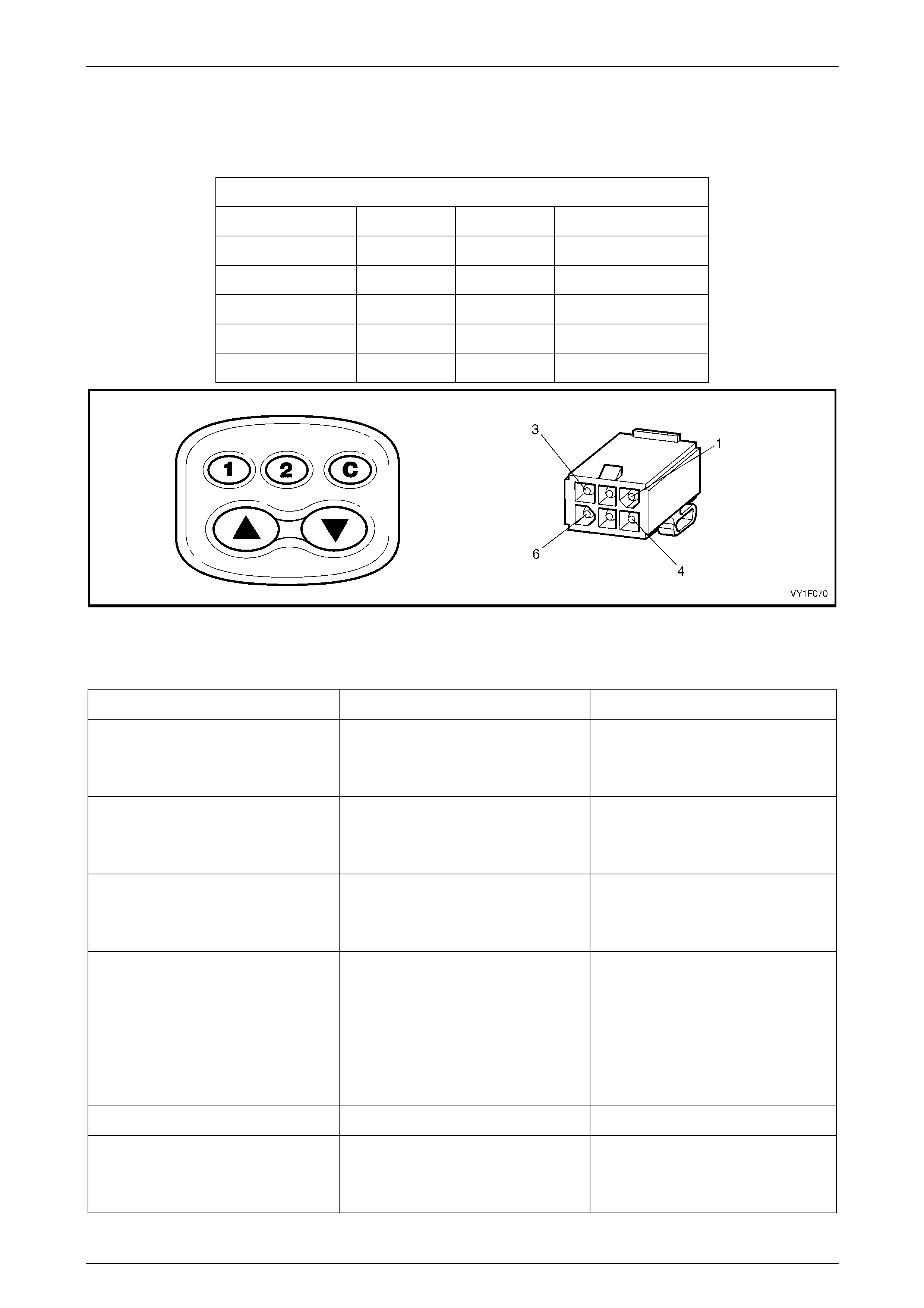
Sunroof Switch and Sunroof Control Harness Test
Press the switch buttons and place the multimeter probe tips onto the pins of sunroof control harness connector X321.
Ensure reading is as indicated in the chart below. Refer to Figure 1F2 – 3.
Sunroof Switch and Sunroof Control Harness
Press Switch + Lead – Lead Indication
! button Pin 3 Pin 5 Continuity
" button Pin 3 Pin 2 Continuity
C button Pin 6 Pin 4 Continuity
1 button Pin 6 Pin 5 Continuity
2 button Pin 6 Pin 2 Continuity
Figure 1F2 – 3
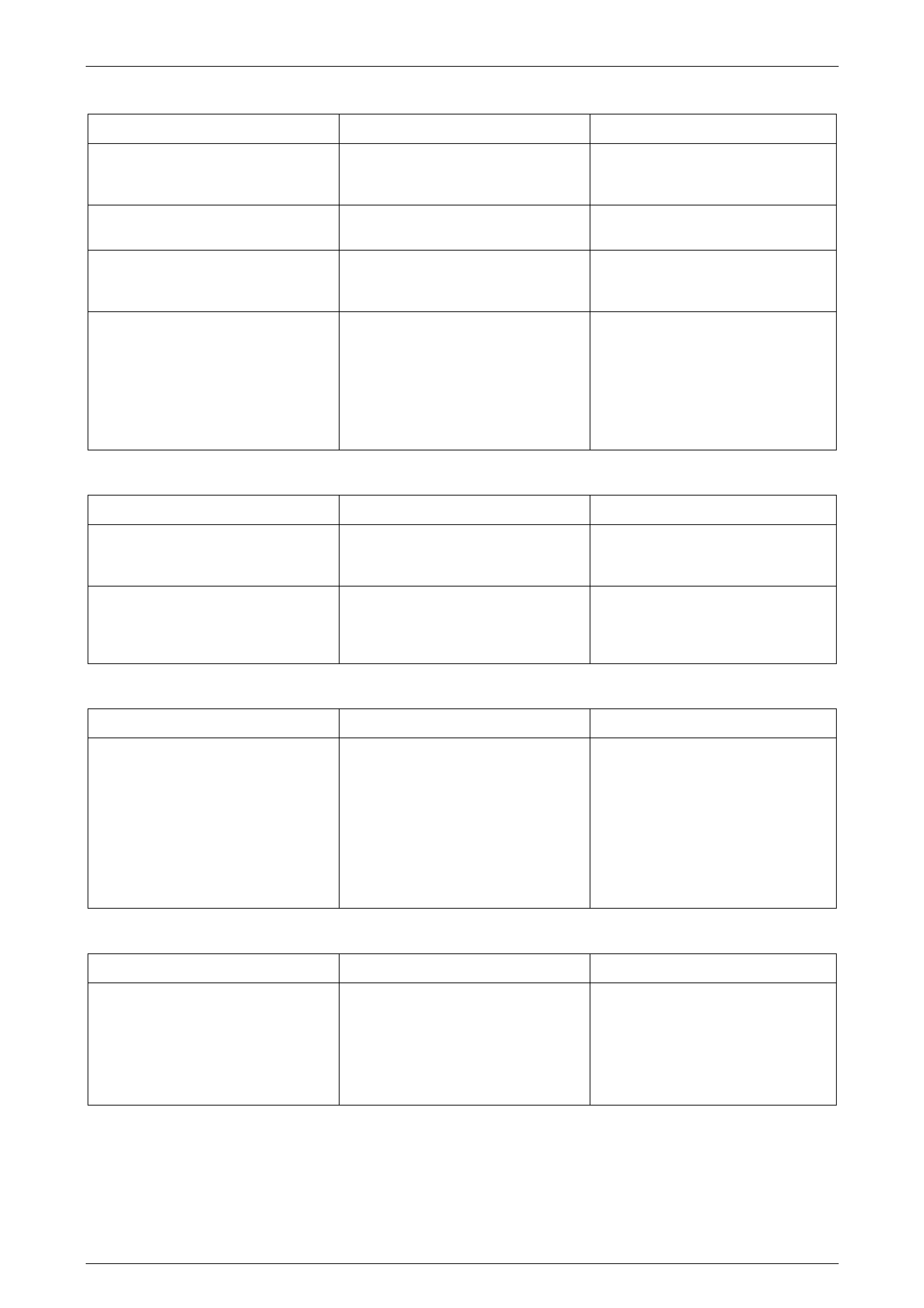
Repair Advice For Mechanical Failures
Problem Possible Cause Solution
While closing the panel from the tilt
position, the panel begins to slide
rearward.
Blocking catch is brok en. Replace the blocking catch, refer to
Section 1F2, 2.16 Blocking Catch in
the MY 2003 VY and V2 Series
Service Informatio n.
While closing the panel from the fully
opened position, the panel begins to
tilt under the roof skin.
Blocking catch is brok en. Replace the blocking catch, refer to
Section 1F2, 2.16 Blocking Catch in
the MY 2003 VY and V2 Series
Service Informatio n.
Panel is misaligned side to side. Timing of drive cables is incorrect. Re-time the drive cables, refer to
Section 1F2, 2.13 Timing Of Drive
Cables in the MY 2003 VY and V2
Series Service Inform ation.
Panel is sliding too slowly. With a
13.5 V power supply, the panel should
not take more than 7 seconds to close
from the fully opened position.
1 Misaligned panel creating drag or
friction.
2 Dirty mechanism.
1 Re-time the drive cables, refer
to Sect ion 1F2, 2.13 Timing Of
Drive Cables in the MY 2003 VY
and V2 Series Service
Information.
2 Clean and grease the
mechanism or replace if
necessary.
Glass panel stops prematurely. Obstacle in mechanism or guide rail. Remove the obstacle.
Sunshade fails to open when the glass
panel is opened to tilt position. Retraction mechanism is broken. Replace the retraction mechanism,
refer to Section 1F2, 2.14 Retraction
Mechanism in the MY 2003 VY and
V2 Series Service Information.
Sunroof – Online Page 1F2–16
Page 1F2–16
Repair Ad vice For Electrical Failures
Problem Possible Cause Solution
The sunroof operates but the
auto-close and soft touch functions do
not operate.
Insufficient voltage supplied to the
sunroof (bad battery). Check the power supply/battery, refer
to Section 12A Battery and Cables.
Clicking noises from the SCU and the
panel does not slide. Voltage too low. Check the power supply/battery, refer
to Section 12A Battery and Cables.
The SCU is clicking in open position,
but the sunroof does not close with
continuous pressing of the C button.
Voltage drop in power supply. Cut off the power supply briefly
(remove fuse F105), reset the
programmable positions.
The panel is sliding too slowly. With a
13.5 V power supply, the panel should
not take more than 7 seconds to close
from the fully opened position.
1 Weak battery.
2 Weak motor. Test as detailed in
this Section.
1 Charge or replace the battery,
refer to Section 12A Battery and
Cables.
2 Replace the drive motor, refer to
Section 1F2, 2.1 Drive Motor in
the MY 2003 VY and V2 Series
Service Information.
Repair Advice For Rattling Noises
Problem Possible Cause Solution
The drain channel rattles. Check if insulator tape is applied
between drain channel and
mechanism.
Add insulator tape.
Rattling in motor area. Drive motor cover screws loose. Tighten drive motor cover screws,
refer to Section 1F2, 2.1 Drive Motor
in the MY 2003 VY and V2 Series
Service Informatio n.
Repair Advice For Wind Noises
Problem Possible Cause Solution
Excessive wind noise when the glass
panel is in the closed position. 1 Glass panel seal is not fitting
securely against the roof panel.
2 Blocking catch is broken.
1 Adjust the glas s panel seal,
refer to Section 1F2, 2.8 Rubber
Seal in the MY 2003 VY and V2
Series Service Inform ation.
2 Replace the blocking catch,
refer to Section 1F2,
2.16 Blocking Catch in the MY
2003 VY and V2 Series Service
Information.
Repair Advice For Water Leaks
Problem Possible Cause Solution
Water coming through the pan el
opening area. 1 Blocked drain tube/s.
2 Misaligned or kinked drai n tub es.
1 Inspect the drain tubes outlet
and the grommets. Blow out
drain tubes.
2 Correct the routeing of the drain
tubes, refer to 2.3 Rear Drain
Tube.
Sunroof – Online Page 1F2–17
Page 1F2–17
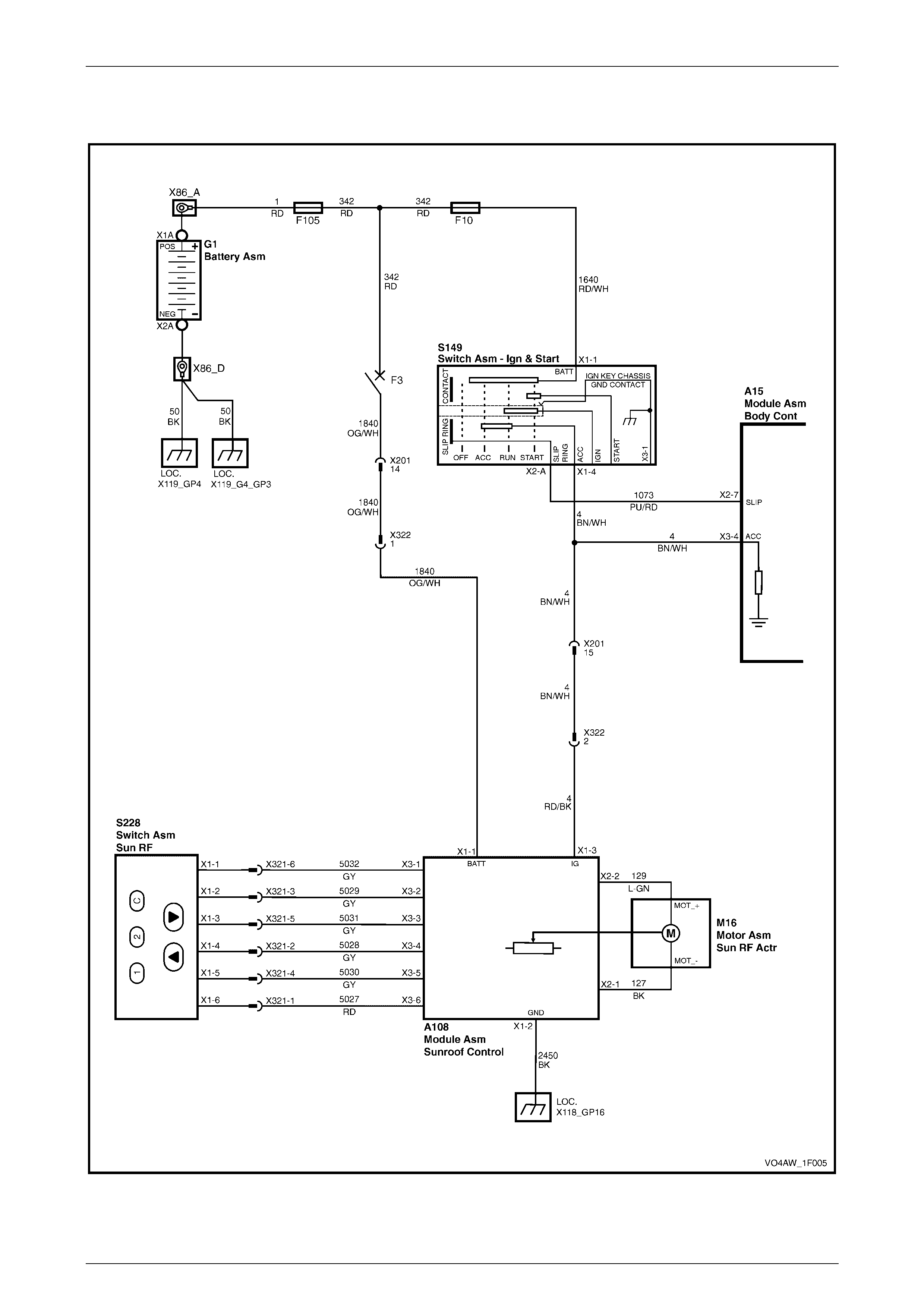
3.2 Wiring Diagram – Sunroof
Figure 1F2 – 4
Sunroof – Online Page 1F2–18
Page 1F2–18
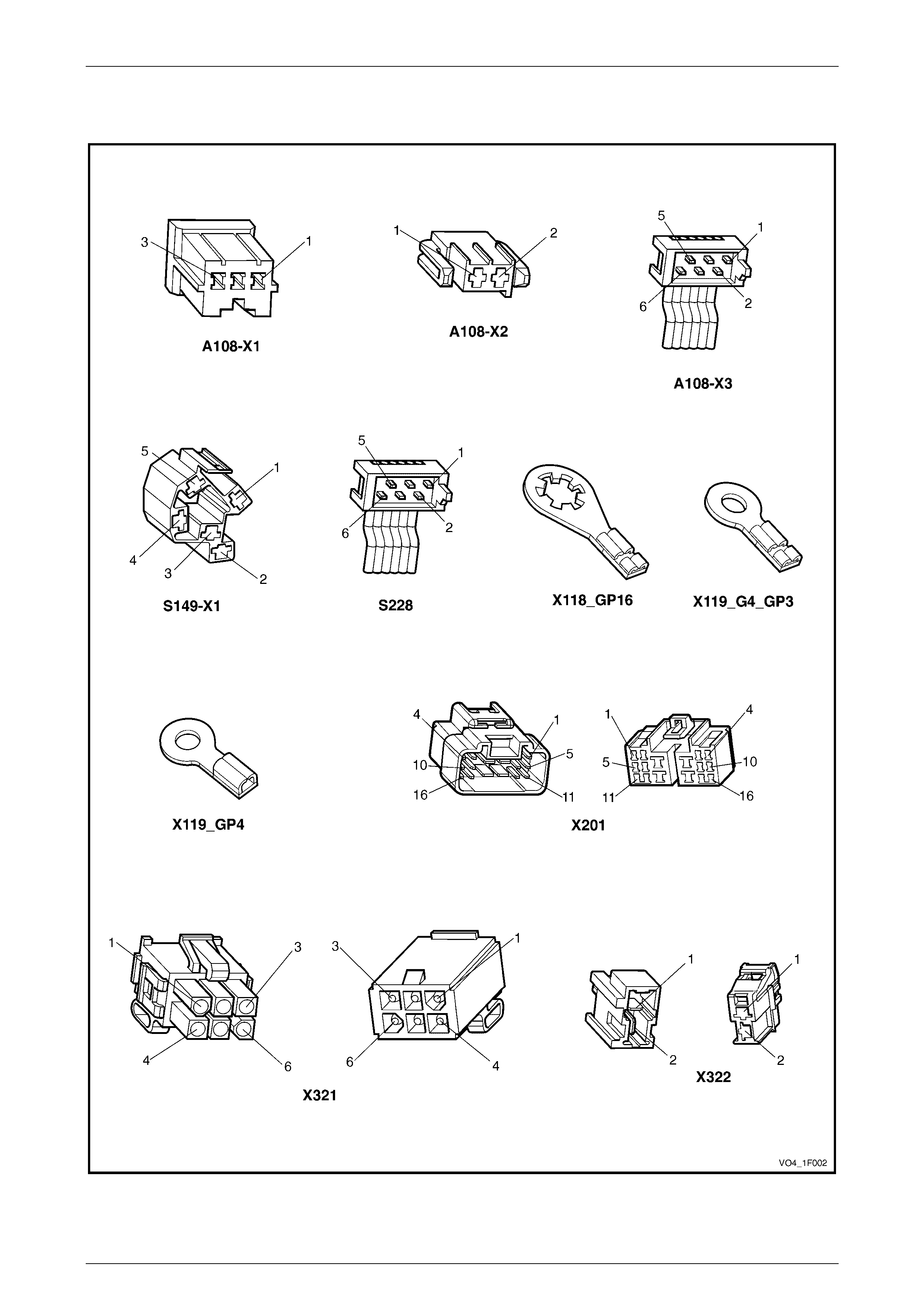
3.3 Connector Diagrams – Sunroof
Figure 1F2 – 5

Sunroof – Online Page 1F2–19
Page 1F2–19
4 Torque Wrench Specifications
Sunroof power harness ground screw...........................................1.5 – 3.0 Nm