
Lighting System Page 12B–1
Page 12B–1
Section 12B
Lighting System
ATTENTION
Before performing any service operation or other procedure described in this Section, refer to Section 00
Warnings, Cautions and Notes for correct w orkshop practices with regard to safety and/or property damage.
1 General Information............................................................................................................................... 2
1.1 Tail Lamp Assembly...............................................................................................................................................3
1.2 Backup Lamp Assembly........................................................................................................................................4
2 Service Operations................................................................................................................................ 5
2.1 Fog Lamps..............................................................................................................................................................5
Fog Lamp Assembly..............................................................................................................................................5
Disassemble.......................................................................................................................................................5
Reinstallation......................................................................................................................................................5
Fog Lamp Assembly Bulbs ...................................................................................................................................6
Replacement ......................................................................................................................................................6
2.2 Tail Lamps ..............................................................................................................................................................7
Tail Lamp Assembly...............................................................................................................................................7
Removal .............................................................................................................................................................7
Reinstallation......................................................................................................................................................7
Tail Lamp Assembly Bulbs....................................................................................................................................7
Replacement ......................................................................................................................................................7
2.3 Backup Lamps ........................................................................................................................................................8
Backup Lamp Assembly........................................................................................................................................8
Removal .............................................................................................................................................................8
Reinstallation......................................................................................................................................................8
Backup Lamp Assembly Bulbs.............................................................................................................................8
Replacement ......................................................................................................................................................8
2.4 Liftgate Air Deflector Assembly and High Mount Stop Lamp Assembly...........................................................9
Liftgate Air Deflector Assembly and High Mount Stop Lamp Assembly...........................................................9
2.5 Inclinometer Assembly........................................................................................................................................10
Inclinometer Assembly........................................................................................................................................10
Inclinometer Assembly Bulbs.............................................................................................................................10
Replacement ....................................................................................................................................................10
3 Torque Wrench Specifications........................................................................................................... 11
Techline
Lighting System Page 12B–2
Page 12B–2
1 General Information
With the following exceptions, MY 2004 VY AWD Wagon Lighting System information carries over from MY 2003 VY
and V2 Series:
• fog lamps,
• tail lamps,
• backup lamps,
• liftgate air deflector assembly and high mount stop lamp assembly.
(A new liftgate air deflector assembly and high mount stop lamp assembly is fitted as standard equipment on
MY 2004 VY AWD Wagon vehicles, refer to Section 1A4 Hood, Rear Compartment Lid, Liftgate and Endgate.)
• inclinometer assembly lamps, and
(An inclinometer is fitted as standard equipment on high-level MY 2004 VY AWD Wagon vehicles, refer to
Section 1A3 Instrument Panel and Console.)
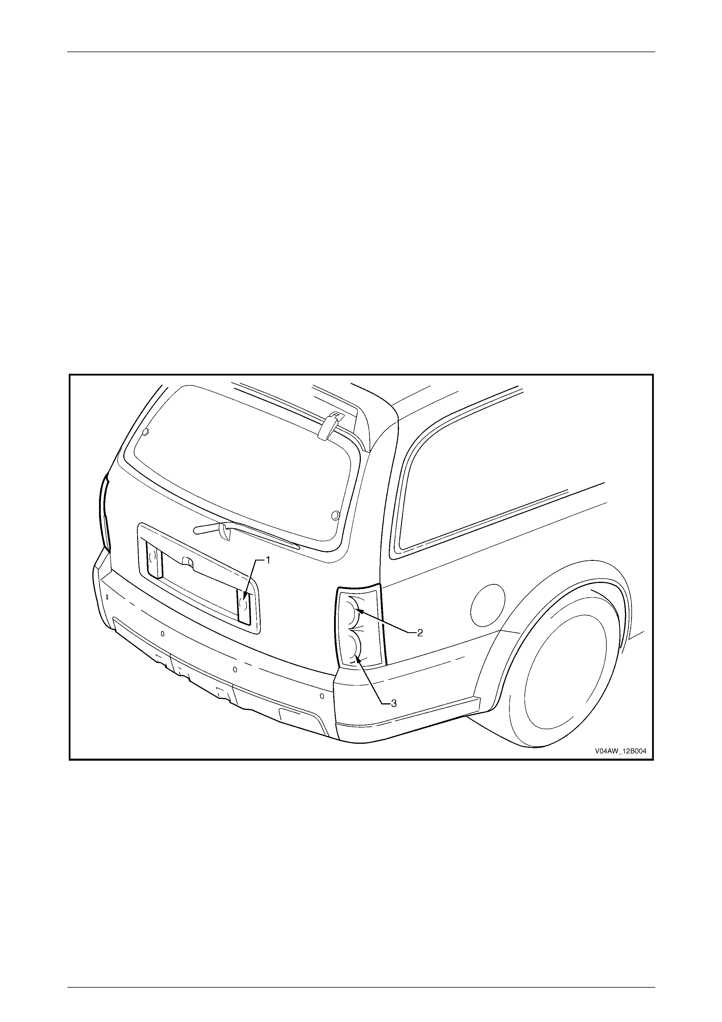
For a general view of the tail lamp assemblies and backup lamp assemblies, refer to Figure 12B – 1.
For information not contained within this Section, refer to Section 12B Lighting System in the MY 2003 VY and V2 Series
Service Information.
Figure 12B – 1
Legend
1 Backup Lamp 2 Stop/Tail Lamp
3 Turn Lamp
Lighting System Page 12B–3
Page 12B–3
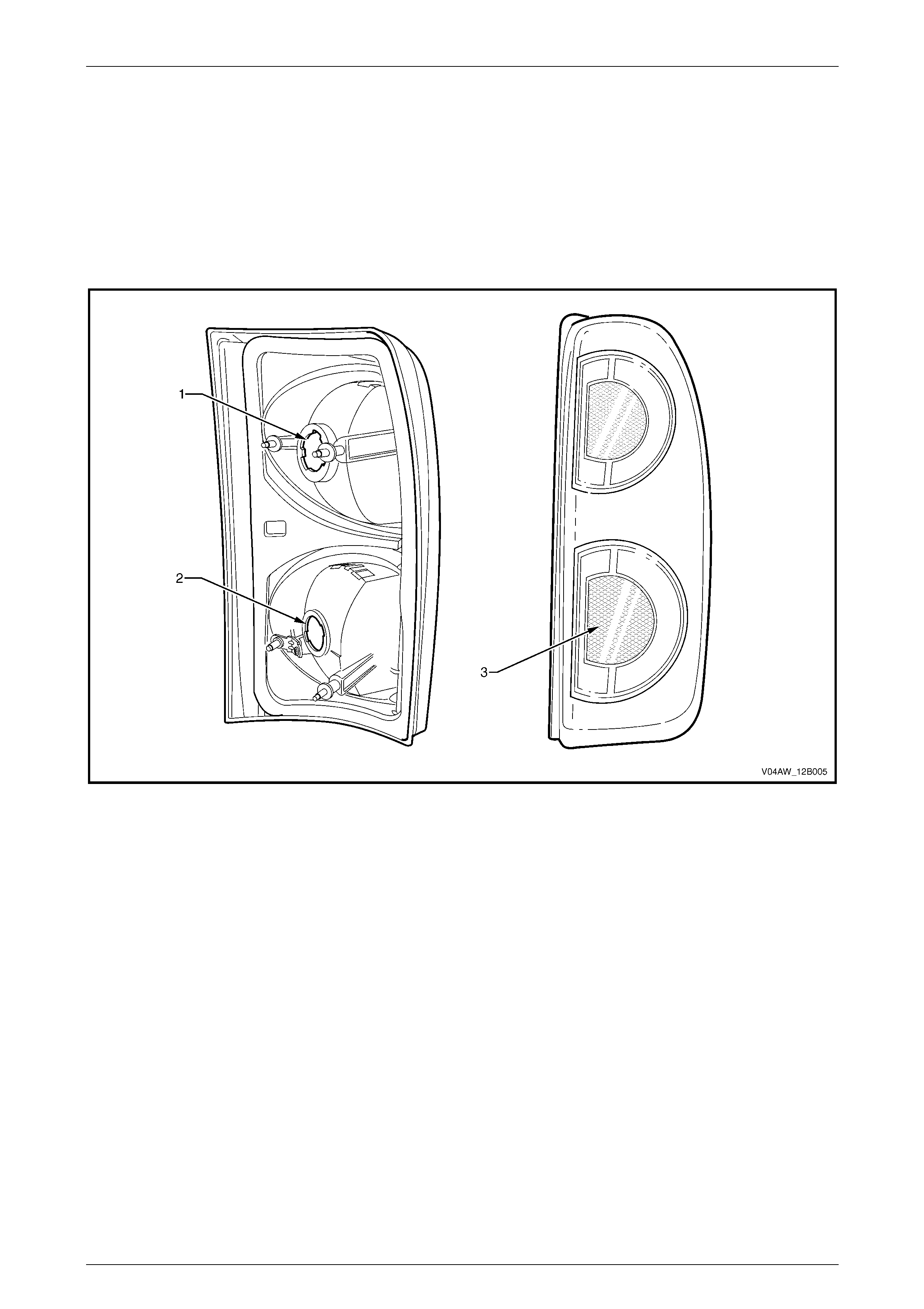
1.1 Tail Lamp Assembly
MY 2004 VY AWD Wagon tail lamp assemblies consist of:
• a turn signal lamp,
• a stop/tail lamp, and
• a reflex reflector.
For internal and external views of the tail lamp assembly, refer to Figure 12B – 2.
Figure 12B – 2
Legend
1 Stop/Tail Lamp
2 Turn Lamp 3 Reflex Reflector
Lighting System Page 12B–4
Page 12B–4
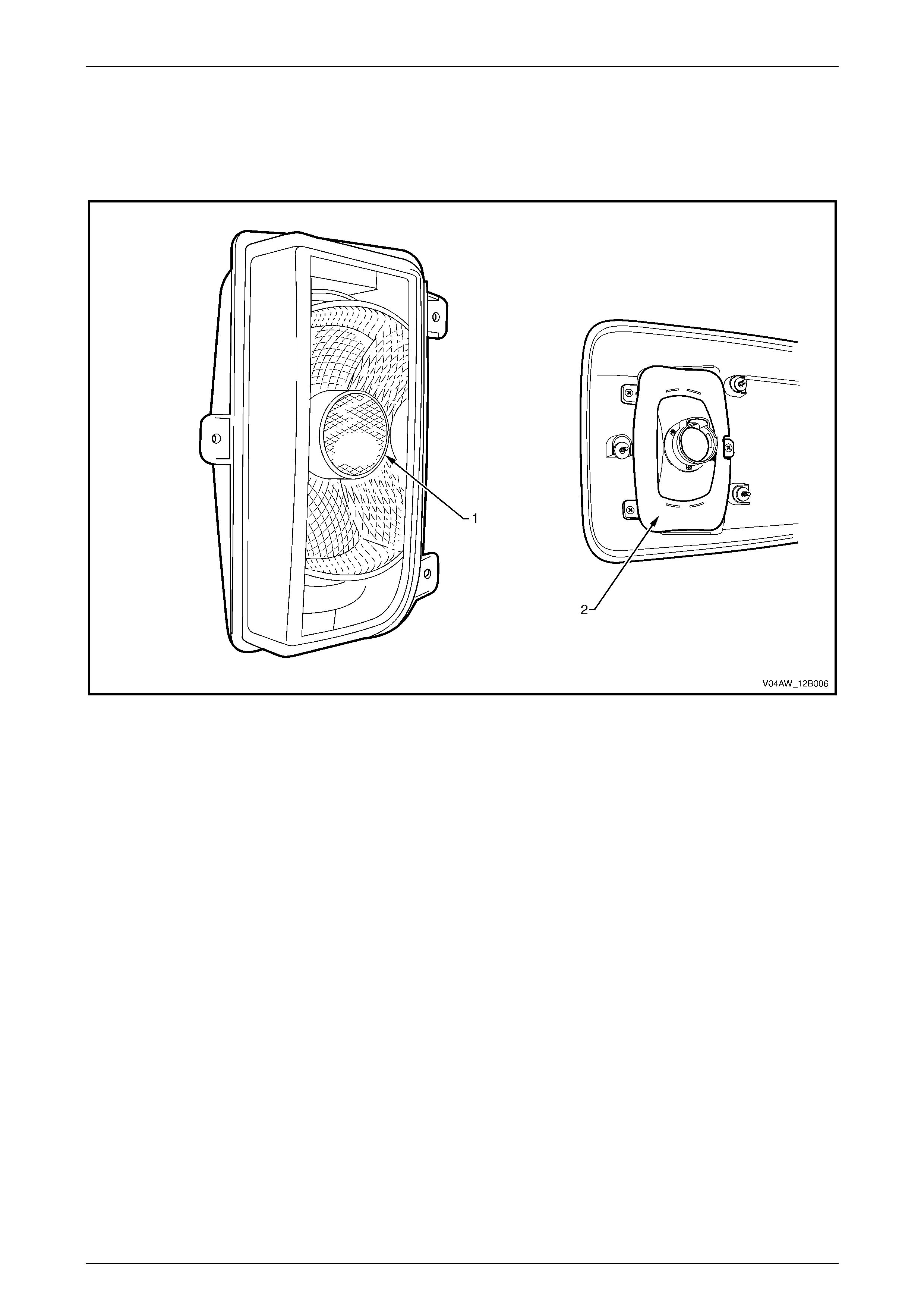
1.2 Backup Lamp Assembly
The MY 2004 VY AWD Wagon backup lamp assemblies are attached to the liftgate appliqué assembly.
For internal and external views of the backup lamp assembly, refer to Figure 12B – 3.
Figure 12B – 3
Legend
1 Backup Lamp As sembly 2 Foam Rubber Seal
Lighting System Page 12B–5
Page 12B–5
2 Service Operations
2.1 Fog Lamps
LT Section –
Fog Lamp Assembl y
Removal, disassembly and aiming procedures for the fog lamp assembly are carried over from MY 2003 VY and
V2 Series vehicles, refer to Section 12B Lighting System in the MY 2003 VY and V2 Series Service Information.
Disassemble
For the fog lamp assembly disassembly procedure, refer to Section 12B Lighting System in the MY 2003 VY and
V2 Series Service Information.
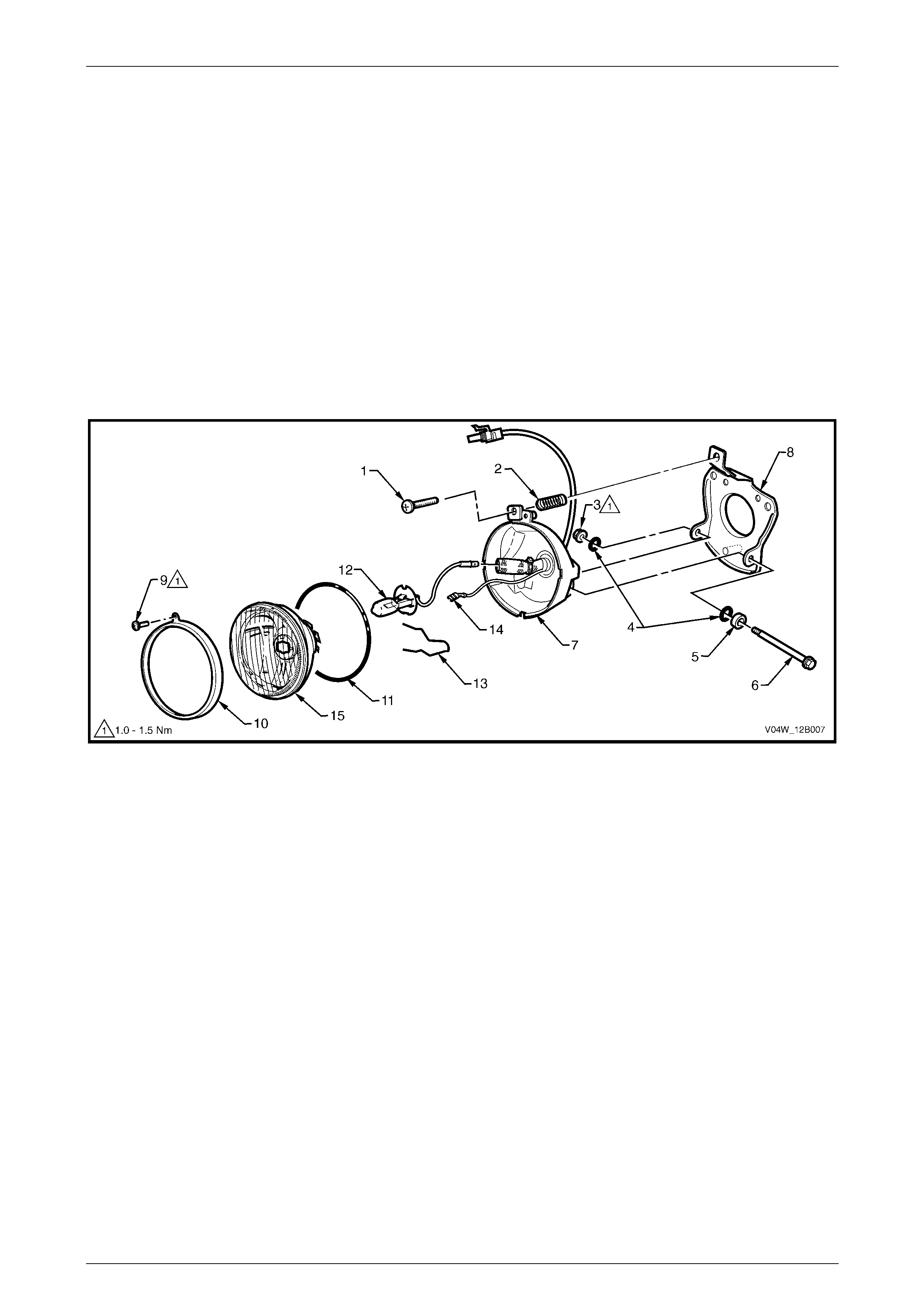
Figure 12B – 4
Legend
1 Adjusting Screw
2 Spring
3 Nut
4 Seals
5 Spacer
6 Bolt
7 Lens and Reflector Housing
8 Mounting Bracket
9 Screw
10 Clamp Ring
11 Foam Rubber Seal i ng Ri ng
12 Bulb
13 Retaining Spring
14 Ground Lead Connector
15 Lens and Reflector As sembly
Reinstallation
NOTE
The fog lamp assembly on the MY 2004 VY AWD
Wagon has a foam rubber sealing ring behind
the lens and reflector housing that protects the
internal components of the fog lamp from water
damage (refer to Figure 12B – 4). Before
reinstalling, either clean or replace the foam
rubber sealing ring.
Reinstallation of the fog lamps is the reverse of the removal procedure, noting the following:
1 Ensure the correct placement of the foam rubber sealing ring behind the lens and reflector housing.

Lighting System Page 12B–6
Page 12B–6
2 Tighten the fog lamp assembly retaining nut and fog lamp assembly retaining screws to the following torque
specifications:
Fog lamp assembly retaining screws
torque specification.................................... 2.0 – 5.0 Nm
Fog lamp assembly retaining nuts
torque specification.................................... 2.0 – 5.0 Nm
Fog Lamp Assembl y Bulbs
Replacement
For the fog lamp assembly bulb replacement procedure, refer to Section 12B Lighting System in the MY 2003 VY and
V2 Series Service Information, noting the following:
NOTE
The MY 2004 VY AWD Wagon fog lamp
assembly has a foam rubber sealing ring behind
the lens and reflector housing that protects the
internal components of the fog lamp from water
damage.

Lighting System Page 12B–7
Page 12B–7
2.2 Tail Lamps
LT Section –
Tail Lamp Assembl y
NOTE
The backup lamp has been removed from the
MY 2004 VY AWD Wagon tail lamp assembly.
The MY 2004 VY AWD Wagon tail lamp
assembly and the MY 2003 VY and V2 Series tail
lamp assembly are not compatible.
Removal
For the tail lamp assembly removal procedure, refer to Section 12B Lighting System in the MY 2003 VY and V2 Series
Service Information.
Reinstallation
Reinstallation of the tail lamp assembly is the reverse of the removal procedure, refer to Section 12B Lighting System in
the MY 2003 VY and V2 Series Service Information, noting the following:
• The turn signal lamp has an amber socket assembly and is located in the bottom section of the tail lamp
assembly.
• The stop/tail lamp has a grey socket assembly and is located in the top section of the tail lamp assembly.
Both the turn signal lamp and stop/tail lamp also have different lug configurations to prevent installation into the
incorrect tail lamp assembly receptacle.
Tail Lamp Assembl y Bulbs
Replacement
For the tail lamp assembly bulb replacement procedure, refer to Section 12B Lighting System in the MY 2003 VY and
V2 Series Service Information.
Lighting System Page 12B–8
Page 12B–8
2.3 Backup Lamps
LT Section –
Backup Lamp Assembl y
Removal
1 Remove the liftgate appliqué assembly, refer to Section 1A4 Hood, Rear Compartment Lid, Liftgate and Endgate.
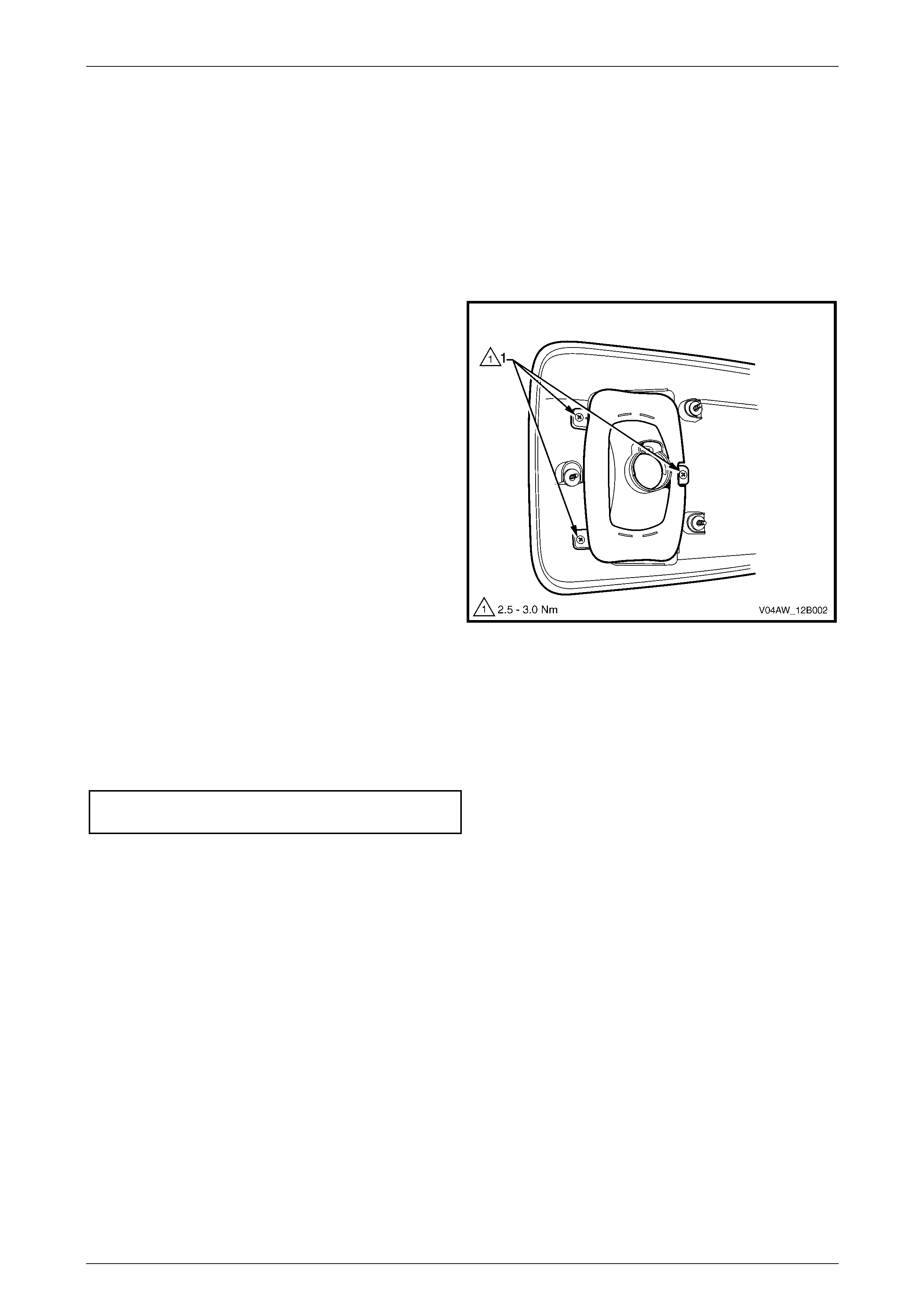
2 Remove the three Phillips screws (1) attaching the
backup lamp assembly to the liftgate appliqué
assembly.
Figure 12B – 5
Reinstallation
Reinstallation of the backup lamp assembly is the reverse of the removal procedure, noting the following:
1 Inspect the foam rubber seal (refer to Figure 12B – 3) for damage and replace if necessary.
2 Tighten the backup lamp assembly attaching screws to the correct torque specification.
Backup lamp assembly
attaching screw torque specification.......... 2.5 – 3.0 Nm
Backup Lamp Assembl y Bulbs
Replacement
1 Remove fusible link F102, refer to Section 12O Fuses, Relays and Wiring Harnesses.
2 Remove the liftgate lower trim panel, refer to Section 1A4 Hood, Rear Compartment Lid, Liftgate and Endgate.
3 Remove the bulb from the socket assembly by pressing the bulb, then rotating it anticlockwise.
4 Inspect the socket assembly seal for damage and replace if necessary.
5 Insert a new bulb into the socket assembly and fit the socket assembly into the backup lamp assembly, ensuring
the socket assembly locks securely into place.
6 Replace fusible link F102, refer to Section 12O Fuses, Relays and Wiring Harnesses.
7 Turn the ignition switch to the RUN position and check the bac kup lamp operation by confirming the backup lamps
illuminate.

Lighting System Page 12B–9
Page 12B–9
2.4 Liftgate Air Deflector Assembly and High
Mount Stop Lamp Assembly
LT Section –
Liftgat e Air Deflector Assembly and High Mount Stop Lamp Assembly
For service operations for the liftgate air deflector assembly and high mount stop lamp assembly, refer to
Section 1A4 Hood, Rear Compartment Lid, Liftgate and Endgate.
Lighting System Page 12B–10
Page 12B–10
2.5 Inclinometer Assembly
LT Section –
Inclinometer Assembly
For service operations for the inclinometer assembly, refer to Section 1A3 Instrument Panel and Console.
Inclinomet er Assembly Bulbs
Replacement
1 Remove fusible link F102, refer to Section 12O Fuses, Relays and Wiring Harnesses.
2 Remove the inclinometer assembly, refer to Section 1A3 Instrument Panel and Console.
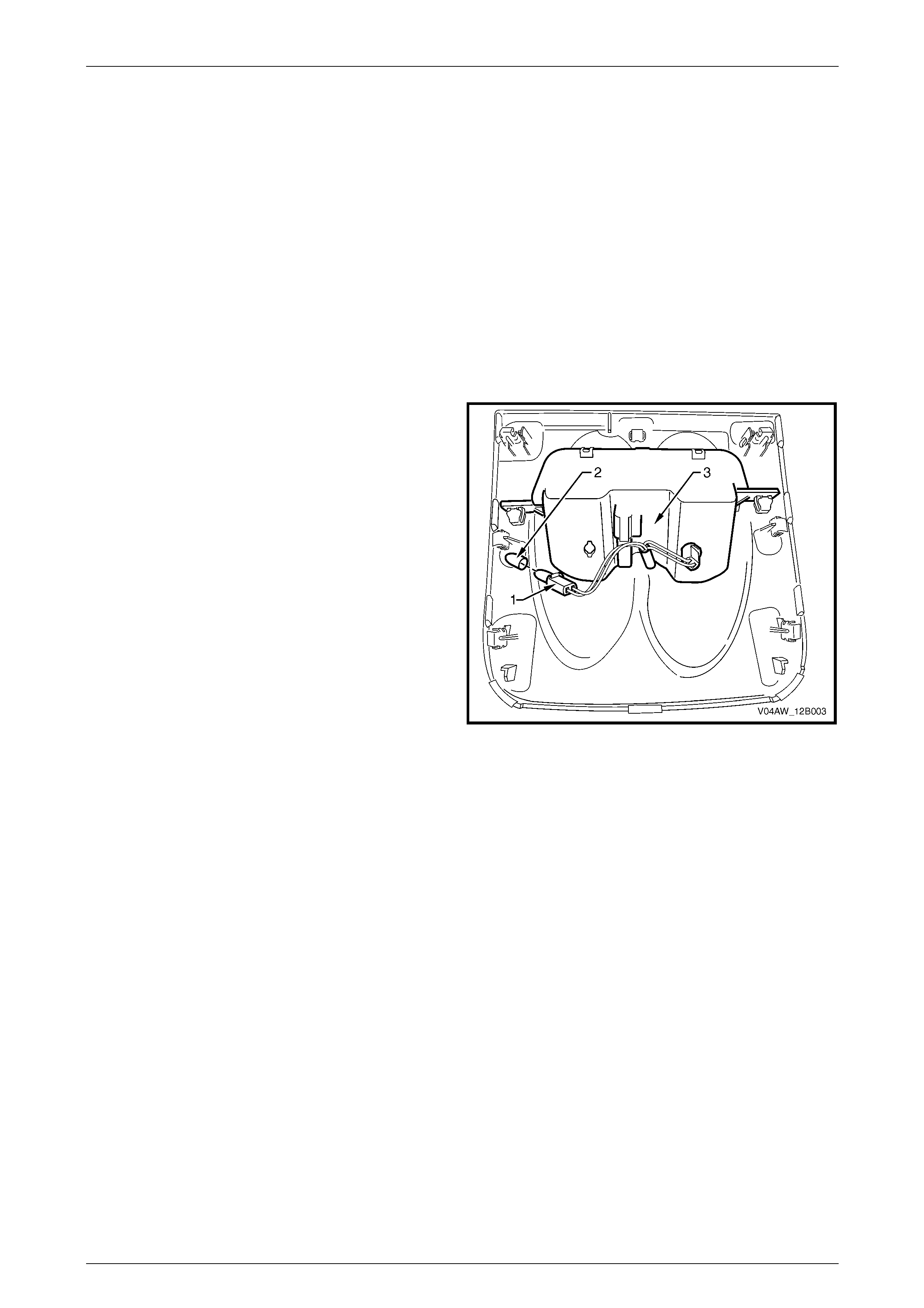
3 Rotate the socket assembly (1) and remove from the
inclinometer assembly (3).
4 Remove the green bulb sleeve (2) from the bulb while
it is in the socket assembly.
5 Replace the failed bulb.
6 Fit the green bulb sleeve to the new bulb.
7 Fit the socket assembly to the inclinometer assembly.
8 Install the inclinometer assembly, refer to Section 1A3
Instrument Panel and Console.
9 Replace fusible link F102, refer to Section 12O Fuses,
Relays and Wiring Harnesses.
10 Turn the ignition switch to the PARK position and
check the inclinometer lamp operation by confirming
the inclinometer lamps illuminate.
Figure 12B – 6

Lighting System Page 12B–11
Page 12B–11
3 Torque Wrench Specifications
Fog Lamp Assembly Retaining Screws.........................................2.0 – 5.0 Nm
Fog Lamp Assembly Retaining Nuts.............................................2.0 – 5.0 Nm
Backup Lamp Assembly Attaching Screws ...................................2.5 – 3.0 Nm
Inclinometer Assembly Screws......................................................1.0 – 3.0 Nm
Inclinometer Knob Retaining Screw........................................................0.5 Nm