Instruments Page 12C–1
Section 12C
Instruments
ATTENTION
Before performing any Service Operation or other procedure described in this Section, refer to Section 00
Warnings, Cautions and Notes for correct workshop practices with regard to safety and/or property damage.
1 General Information ...............................................................................................................................2
1.1 General Description............................................................................................................................................... 2
Instrument Clusters............................................................................................................................................... 2
Instrument Cluster P3 Connector Terminal Pin Allocatio n.................................................................................. 3
Rear Brake and Park Bulb Failure Indication (LX8 model only) ......................................................................... 6
Instrument Cluster Programming........................................................................................................................ 7
Inclinometer Assembly (LX8 model only)............................................................................................................ 8
Description ......................................................................................................................................................... 8
2 Service Operations.................................................................................................................................9
2.1 Inclinometer............................................................................................................................................................ 9
Indicator Zero Adjustment .................................................................................................................................... 9
Repairs and Maintenance...................................................................................................................................... 9
Removal and Replacement ................................................................................................................................... 9
3 Diagnostics...........................................................................................................................................10
4 Specifications.......................................................................................................................................11
Fuel Calibration Part Number ............................................................................................................................. 11
Speedometer Pulses............................................................................................................................................ 11
Page 12C–1
Techline
Techline
Techline
Techline
Techline
Instruments Page 12C–2
1 General Information
The information contained in this Sectio n relates to instrumentation fitted to MY 2004 AWD Wagon vehicles.
• Instrument Clusters
Both levels of MY 2004 AWD Wagon vehicles are fitted with triple window instrument clusters. The differences
between them are in appeara nce only. An additional feature of detecting Rear Stop a nd Park Lamp Failure failures
is a feature applicable only to LX8 vehicles.
Trip Computer
The added trip computer features of the MY 2004 AWD Wagon triple window instrument clusters are the same as
for high level MY 2003 VY and V2 Series vehicles. For more information regarding these features, refer to
Section 12C 1.5 Trip Computer – Triple Window Cluster in the MY 2003 VY and V2 Series Service Information.
• Inclinometer Assembly
A set of inclinometer gauges is fitted as standard equipment to LX8 models only. Information relating to the
inclinometer assembly is included in this Section.
For all other information relating to instrumentation on MY 2004 AWD W agon vehicles, refer to Section 12C Instruments
in the MY 2004 VY and V2 Series vehicles.
1.1 General Description
The only functional difference between the two instrument clusters as fitted to MY 2004 AWD Wagons is that the LX8
model has the Rear Lamp Failure i ndication feature enabled in the instrument cluster. When activated, it alerts the driver
via a graphic image appearing on the instrument cluster MFD that either a stop or park lamp has faile d.
The LX8 model is also fitted with an inclinometer, which is located in the centre of the instrument panel above the face-
level ventilation outlets.
Instrument Clusters
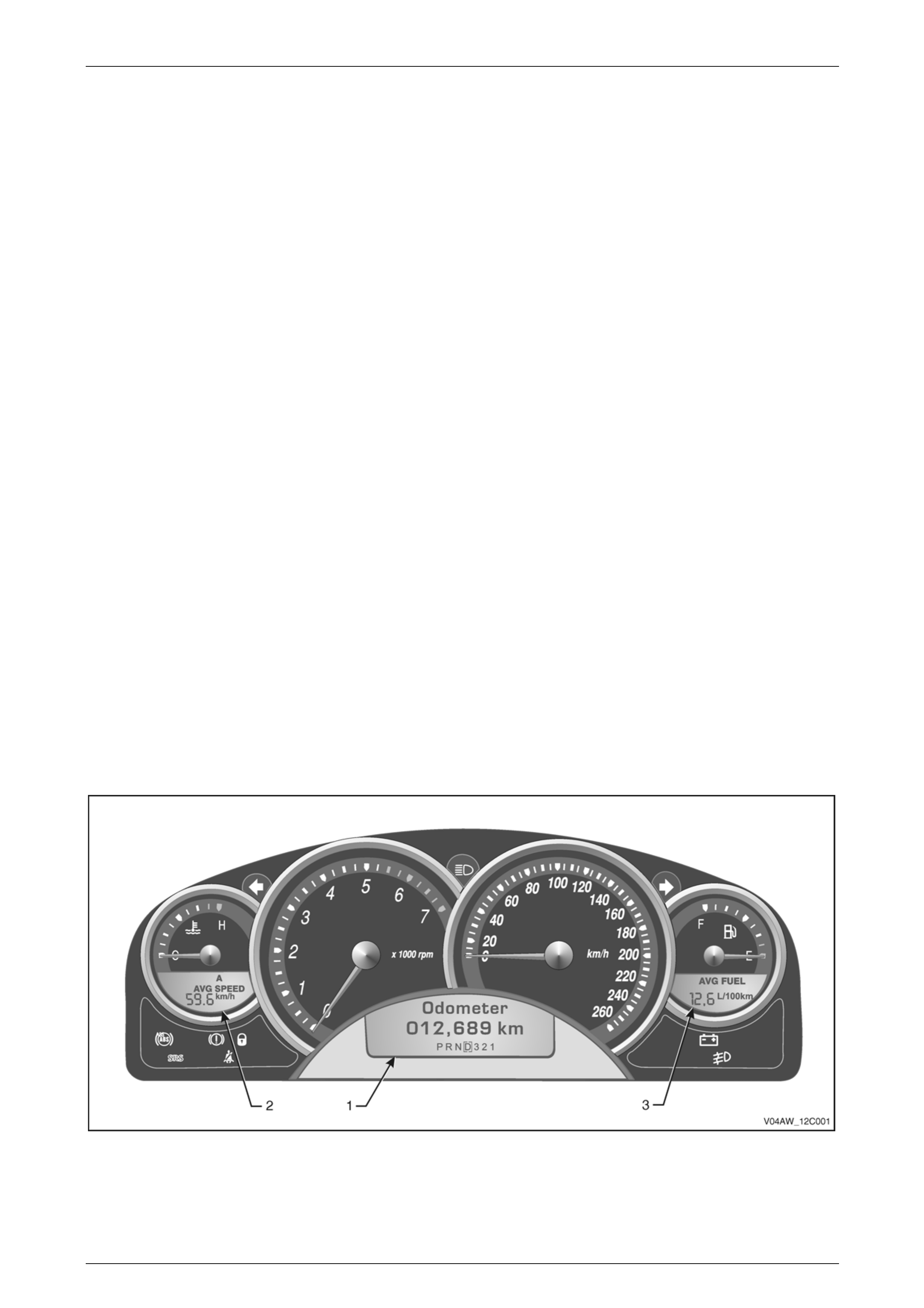
Both the CX8 and the LX8 vehicles use the triple window Multi Function Dis pla y (MFD), as shown below.
Figure 12C – 1 illustrates a typical triple window display, with the MFD indicated as item 1 and the two side Liquid Cr ystal
Displays shown as items 2 and 3.
The physical differences between the CX8 and the LX8 displays relates to their visual appearance only. The LX8 has
satin chrome accent rings around the i nstru ment dials.
Figure 12C – 1
Page 12C–2
Instruments Page 12C–3
The following table identifies the features that are availabl e on the instrument cluster fitted to the MY 2004 AWD Wagon.
Feature Details Colour
Cluster Level Level 3 Black/Grey
Speedo 260 km/h
RPM Redline (Max) 5500 (7000)
Feature Details Colour
Trip Computer Triple Window, English
Trip computer features:
• Audible and visual speed
warning
(4 adjustable settings).
• Average speed
• Odometer
• Average fuel
• Trip time
• Trip distance
• Fuel used
• Time to arrival
• Distance to arrival
• Remaining fuel
• Over Speed
• Distance to empty
• Instantaneous fuel
• Stop watch
• Trip A / B
• Service Due
ABS (Fault / Off) Amber
Alternator Red
Brake (Park / Fail) Red
Front Fog Green
High Beam Blue
Left Turn Arrow Green
Right Turn Arrow Green
Seatbelt Red
Security Red
Warning Lamp Indicators
SRS Red
Page 12C–3

Instruments Page 12C–4
Feature Details Colour
Customisation Mode
(For details refer to Section 12C
1.8 Customisation Mode in the
MY 2003 VY and V2 Series Service
Information)
This mode enables the
following user selectable
features:
• Accessory Control
• Audio Distortion Limiter
• Auto Headlamps Sensitivity
• Auto Lock in Drive
• Confirmation Beeps
• Courtesy Lamp Timeout
• Distance Calibration
• Distance to Arrival Default
• Distance to arrival Display
• Distance to Arrival Display
• Door Lock Indication
• Enter Calibration
Adjustment
• Headlamps Approach Time
• Headlamps Off Delay T ime
• Ignition Off Courtesy Lamp
• Intermittent Wiper Speed
• Radio Display
• Rest Reminder Display
• Restore to Factory Settings
• Speed Dependent Volume
• Stop Watch
• Trip Computer A & B
• Two Stage Unlock
• Underspeed Chime
ABS (Fault / Off)
Alarm (if fitted)
Check Alternator
Check Engine
Cruise Control
Fuel Gauge Error
Low Coolant
Low Fuel
Low Oil Pressure
MFD Indications
Low Traction
Page 12C–4

Instruments Page 12C–5
Feature Details Colour
Odometer
Over Speed
Over Temperature
Park / Brake Fail
Power Shift
PRNDL
Rear Brake Bulb Fail
Rear Lamp Bulb Fail
Rear Lamp Fuse Fail
Rest Reminder
Seat Belt
Service Error
SRS Airbag Fault
Very Low Fuel
Feature Details Colour
ABS
Low Coolant
Mandatory Overspeed
Police
End Of Production Line
Programmable Options
PRNDL
Page 12C–5
Instruments Page 12C–6
Instrument Cluster P3 Connector Terminal Pin Allocation
The following table shows the instrument clu ster pin allocation for MY2004 AWD Wagon vehicles.
Pin Number Function Pin Number Function
X1-1 Battery X1-17 Ground
X1-2 Serial Data X1-18 Trip Computer Switch Return
X1-3 Brakes X1-19 Fuel Level Return
X1-4 Park Lamps X1-20 Ignition
X1-5 Speedometer X1-21 Cruise Control Active
X1-6 Tachometer X1-22 Spare
X1-7 Spare X1-23 Seat Belt
X1-8 Spare X1-24 Low Traction
X1-9 Front Fog Lamps X1-25 Spare
X1-10 Spare X1-26 Spare
X1-11 Right Turn Indicators X1-27 Cruise Control On
X1-12 High Beam X1-28 Trip Computer Switch
X1-13 Charging X1-29 Fuel Level
X1-14 ABS Off X1-30 LPG Fuel Level
X1-15 Left Turn Indicators X1-31 Security Warning
X1-16 Spare X1-32 Spare
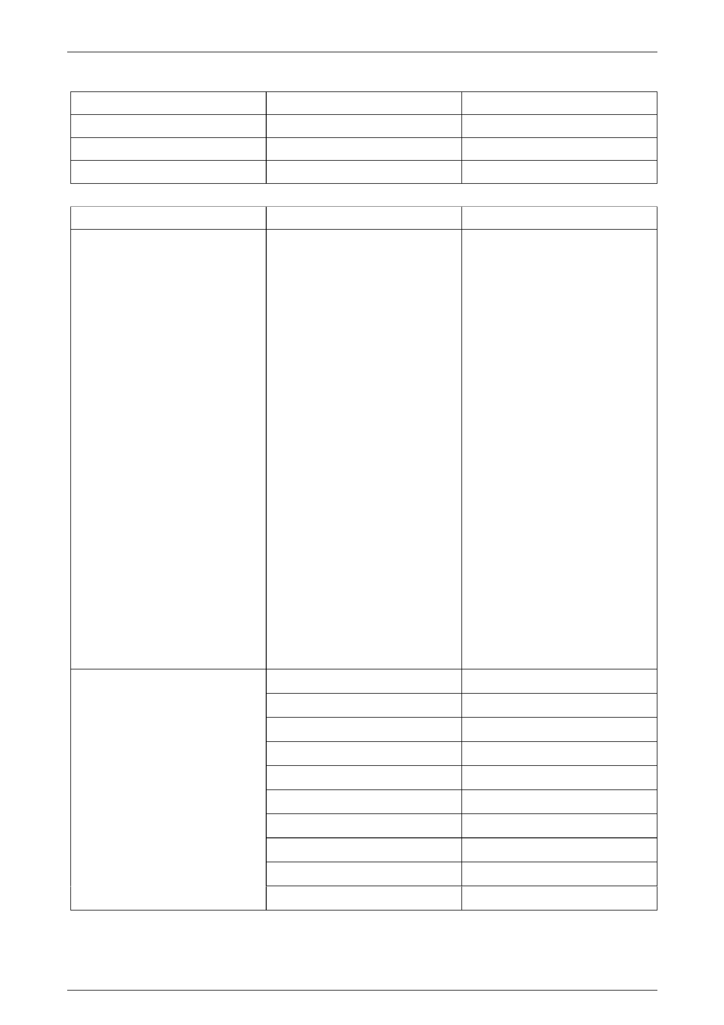
Rear Brake and Park Bulb Failure Indication (LX8 model only)
This feature provides an animated warning message that
appears on the MFD to alert the driver that one of the rear
stop lamps has failed, or is malfunctioning.
This animated message is shown in Figure 12C – 2.
Figure 12C – 2
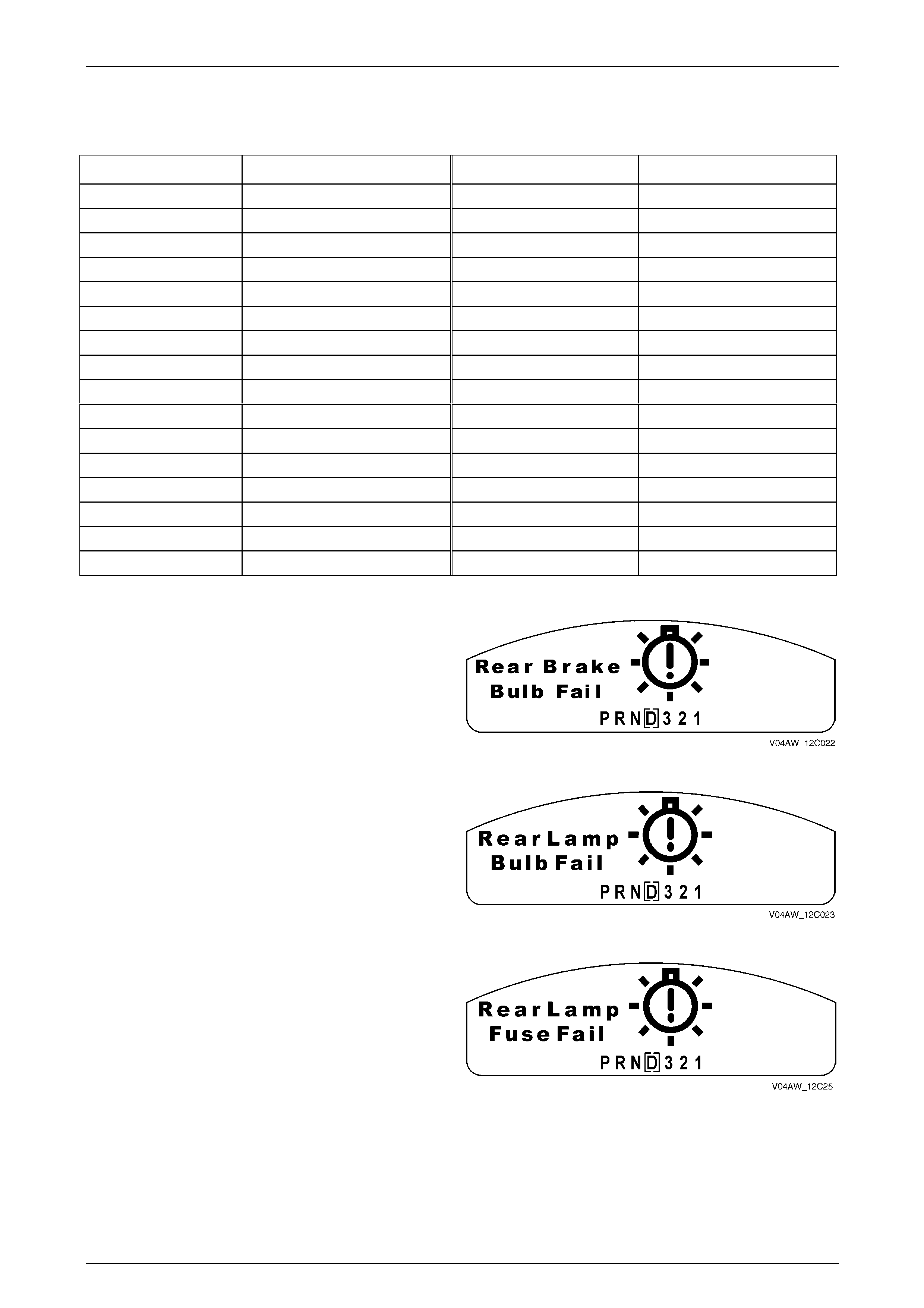
In a similar manner, if one of the rear park lamps fail, the
animated message as shown in Figure 12C – 3 will be
displayed on the MF D.
For more details regarding this feature, refer to MY 2003 VY
and V2 Service Information, Section 12C 1.6 Instrument
Operation – All Models and Section 12J 1.20 Rear Lamp
Failure Warning System.
Figure 12C – 3
This warning message as sho wn in Figure 12C – 4indicates
that a fault has been detected in the stop lamps fuse or the
park lamps fuse.
For more details regarding this feature, refer to MY 2003 VY
and V2 Service Information, Section 12C 1.6 Instrument
Operation – All Models and Section 12J 1.20 Rear Lamp
Failure Warning System.
Figure 12C – 4
Page 12C–6
Instruments Page 12C–7
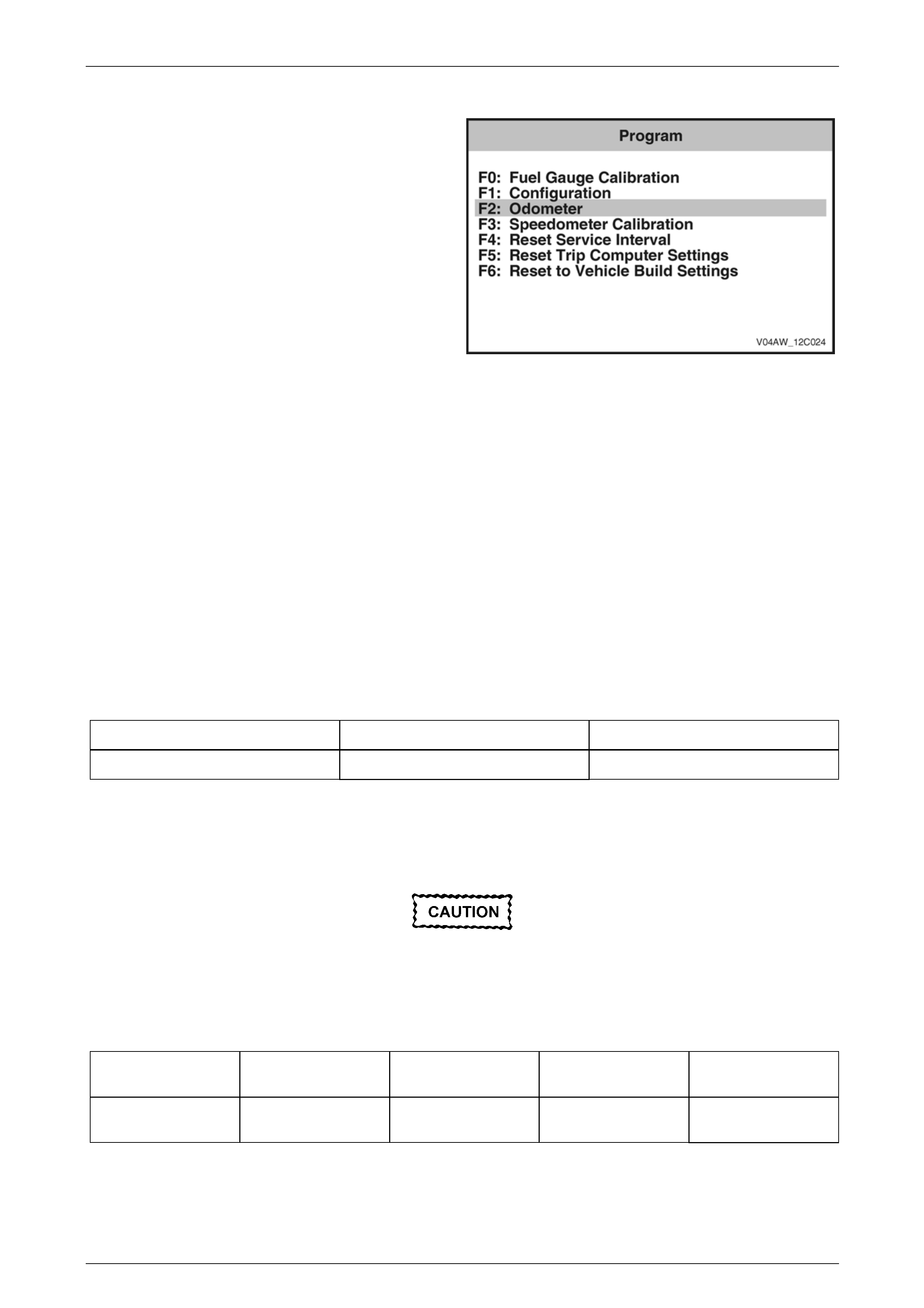
Instrument Cluster Programming
When an instrument cluster is replaced for a ny reason, the
previously installed instrument cluster fuel gauge calibration,
configuration and odometer functions must b e
re-programmed into the replacement instrument cluster
using TECH 2.
NOTE
This is best performed by transferring the
vehicle’s previously programmed details into
TECH 2 by using its Learn feature before
removing the instrument cluster.
For details relating to instrument cluster programming an d
how to enter the required data, refer to Section 12C,
3.15 Program in the MY 2003 VY and V2 Ser ies Service
Information. Figure 12C – 5
If the Learn feature of TECH 2 is not used to transfer the above information, the Fuel Gauge Calibration data, the
Odometer and Speedometer Calibration data applicable to the vehic le is to be manually entered into the instrument
cluster using TECH 2.
These numbers identify:
• the fuel tank size
• the type of fuel sender unit that should be installed (i.e. if it is a forward or reverse resista nce value)
• the resistance values the sender should present to the instrument cluster when the fuel tank is empty and full.
Fuel Calibration Part Number
The Fuel Calibration Part Number is id entified by the Code Index Number, which is associated with a particular vehicl e
configuration. The Code Vers ion Number identifies the software version installed in the instrument cluster. Only the Code
Index Number can be changed by TECH 2.
The Fuel Calibration Part Number an d its related Code Index Number for the MY 2004 VY AWD Wagon vehicles are as
follows:
Vehicle Fuel Calibration Part Number Code index
CX8 and LX8 AWD Wagon 92160975 7/2
Speedometer Pulses
The Speedometer Pulse valu es for the MY 2004 AWD Wagon vehicles are sho wn in the following tabl e. The
Speedometer Pulses sho wn are for the tyre size specified.
If a different tyre size is fitted to the vehicle or
if a different PPK value is entered into the
instrument cluster via TECH 2 that is not in
accordance to what has been specified, the
accuracy of the speedometer readings will be
affected.
Vehicle Engine Transmission Tyre size
Speedometer Pulses
(PPK)
CX8 and LX8 AWD
Wagon V8 Auto 225/55 R17 6726
Page 12C–7
Instruments Page 12C–8
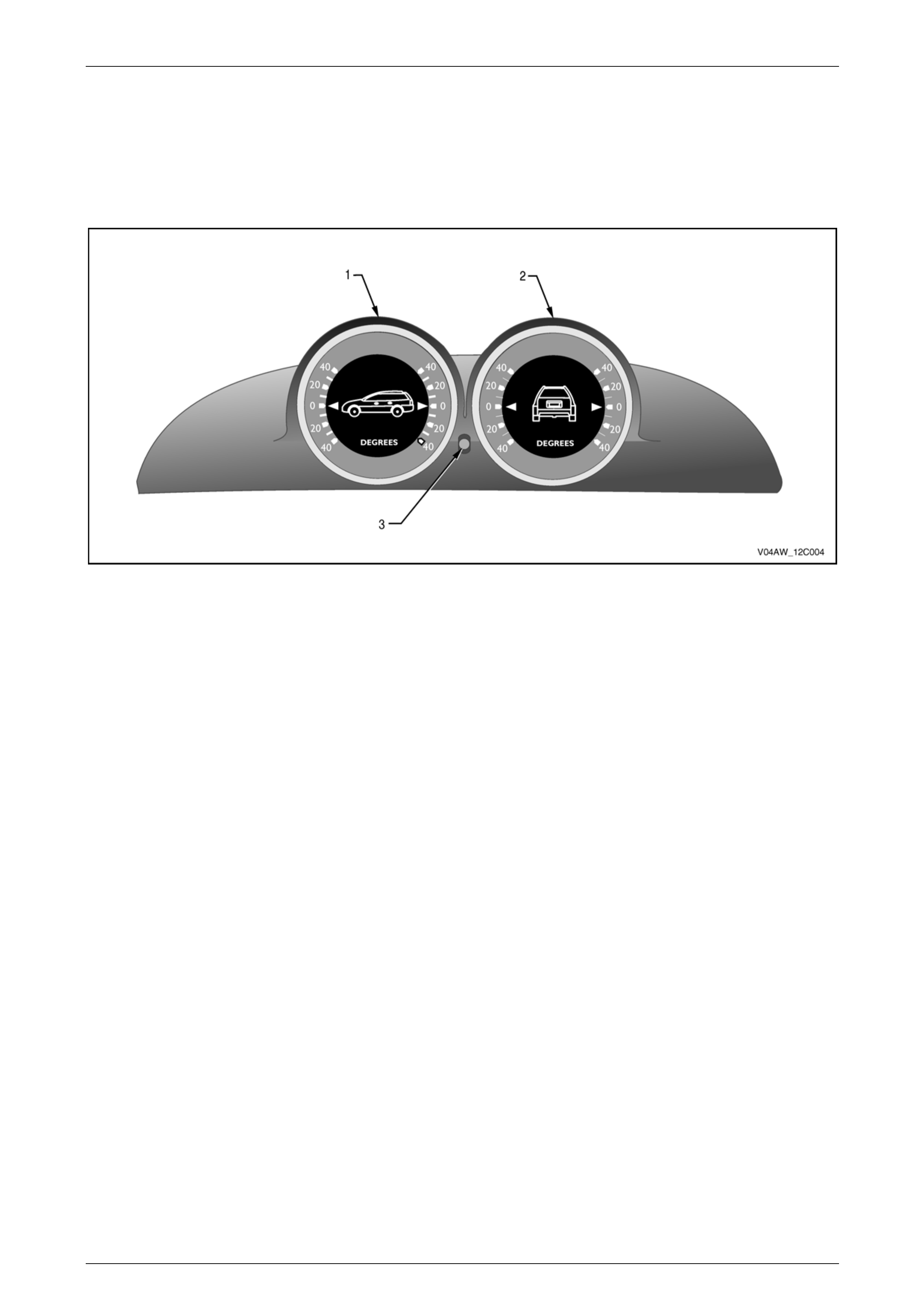
Inclinometer Assembly (LX8 model only)
The inclinometer assembly as shown in Figure 12C – 6 is comprised of two gauges. It is fitted to the LX8 model only.
The left-hand side gau ge (1) indicates the pitch angle between the front and rear of the vehicle. The right-hand side
gauge (2) indicates the roll angle of the vehicle from side to side. A push-pull adjustme nt knob (3) is provided to set the
zero reading of both gauges when the vehicle is on level ground.
Figure 12C – 6
Legend
1. Pitch indicator 2. Roll indicator 3. Push/pull zero adjustment (both gauges)
Description
The gauges of each indicator are mechanically linked to a weighted arm that rotates around a fulcrum point within the
unit. As the vehicle’s angle changes from the level position, the weighted arm rotates ac cordingly. Each arm is
mechanically linked to each dial face, which indicates the changes in vehicl e angle on the gauges. For illumination
information, refer to Section 12J Body Control Module.
A dial zeroing adjustment knob connects to each dial’s mechanical arm when it is either:
• Pushed in to zero adjust the Roll indicator
• Pulled out to zero adjust the Pitch indicator.
Page 12C–8

Instruments Page 12C–9
2 Service Operations
All instruments Service Operations carry over from the MY2003 VY and V2 Series models, except for the inclinometer as
detailed in this Section. For all other Service Operations refer to Section 12C, 2 Service Operations of the MY 2003 VY
and V2 Series Service Information.
2.1 Inclinometer
Indicator Zero Adjustment
To accurately zero the inclinometer gau ges, it is necessary to first locate the vehicle on flat and level terrain. The
indicators can then be zeroed by either pressing or pulling out the adjustment knob identified as item 3 in Figure 12C – 6.
The knob is then rotated accordingly to achieve a zero reading on both gauges.
Repairs and Maintenance
The inclinometer assembl y housing is airtight sealed to keep dust and humidity out of the internal mecha nical
components. If the assembly does not perform as expected, it must be replaced as a unit. The lamps that provide
illumination for the gauges are the only replacement items on the inclinometer assembly. Refer to Section 12B Lighting
System in this Service Information for lamp replacement details.
Removal and Replacement
For details regarding the removal a nd replacement of the inclinometer, refer to Section 1A3, 2.1 Inclinometer Assembly
in this Service Information.
Page 12C–9
Instruments Page 12C–10
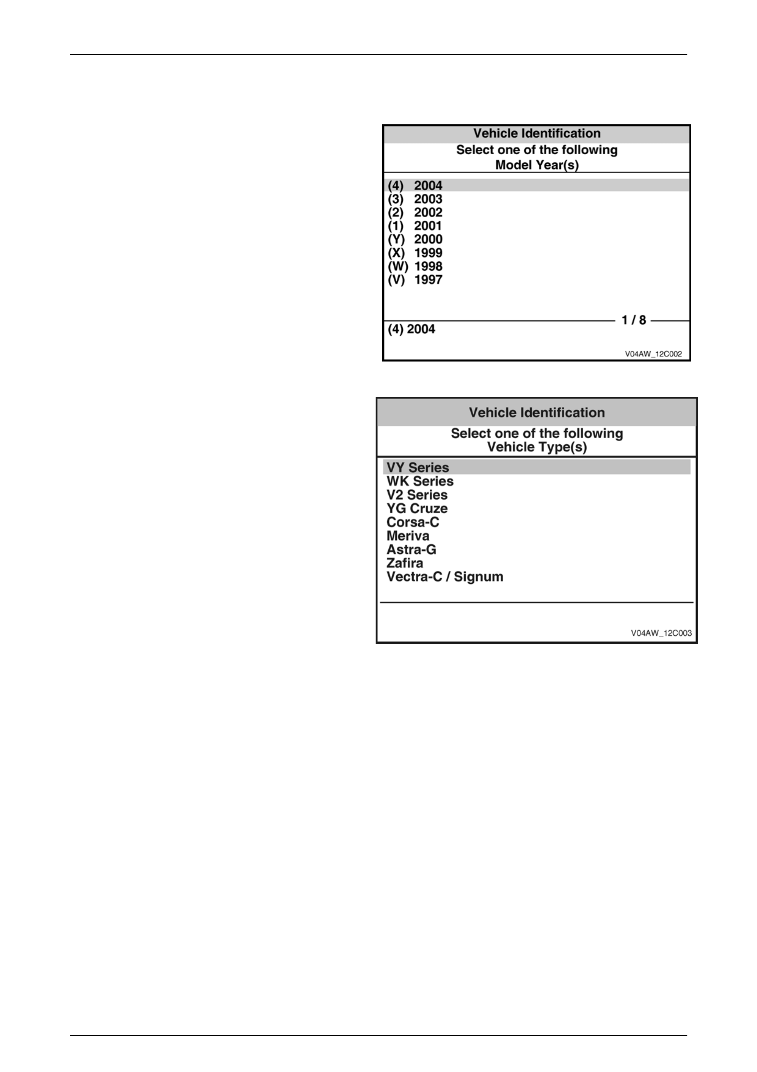
3 Diagnostics
The diagnostic information acc ess procedures are a
carry over from the MY 2003 VY and V2 Series except
that the Model Year selection on TECH 2 is now
(4) 2004.
Figure 12C – 7
The Vehicle Type selection is VY Series.
Figure 12C – 8
Page 12C–10

Instruments Page 12C–11
4 Specifications
Fuel Calibration Part Number
Part Number .............................................................................................................92160975
Code Index / Version Number .............................................................................................7/2
Speedometer Pulses
PPK value.........................................................................................................................6726
Page 12C–11

Instruments Page 12C–8
Page 12C–8
4 Specifications
Fuel Calibration Part Number
Part Number ............................................................................................................. 92160975
Code Index / Version Number............................................................................................. 7/2
Speedometer Pulses
PPK value ........................................................................................................................ 6726