Entertainment System Page 12D–1
Section 12D
Entertainment System
ATTENTION
Before performing any Service Operation or other procedure described in this Section, refer to Section 00
Warnings, Cautions and Notes for correct workshop practices with regard to safety and/or property damage.
1. General Information ...............................................................................................................................2
1.1 General Description............................................................................................................................................... 3
CX8 Model .............................................................................................................................................................. 3
LX8 Model............................................................................................................................................................... 5
Amplifier and Subwoofer.................................................................................................................................... 6
2 Service Operations.................................................................................................................................7
2.1 Subwoofer Speaker ............................................................................................................................................... 7
Remove................................................................................................................................................................... 7
Reinstall.................................................................................................................................................................. 7
2.2 Subwoofer Amplifier.............................................................................................................................................. 8
Remove................................................................................................................................................................... 8
Reinstall.................................................................................................................................................................. 8
3 Diagnostics.............................................................................................................................................9
Main Menu .............................................................................................................................................................. 9
Model Year......................................................................................................................................................... 9
3.1 Program – Audio System .................................................................................................................................... 10
F0: Program Code Index ..................................................................................................................................... 10
3.2 Subwoofer Amplifier............................................................................................................................................ 12
Subwoofer Amplifier Diagnostic Chart.............................................................................................................. 12
4 Specifications.......................................................................................................................................15
Code Index Numbers........................................................................................................................................... 15
Audio System Specifications.............................................................................................................................. 15
CX8 AWD Wagon............................................................................................................................................. 15
LX8 AWD Wagon............................................................................................................................................. 15
5 Torque Wrench Specifications............................................................................................................16
Page 12D–1
Techline
Techline
Techline
Entertainment System Page 12D–2
1. General Information
All MY 2004 AWD Wagon vehicles are fitted with a high performance Blaupunkt entertain ment system that features an
AM / FM stereo radio / CD player combination with height adjustable power antenna. All models also feature illuminated
horn bar mounted remote switches for the operation of the e ntertainment system so that control of the audio system
functions can be accomplished without the need for the driver’s hands to be removed from the steering wheel.
Both LX8 and CX8 models of MY 2004 AWD Wagon vehicles are fitted with the same speaker system as the MY 2003
VY Wagon vehicles. However, LX8 models are also fitted with an additional amplifier an d subwoofer speaker.
Operating instructions for the entertainment system accompany the Owner’s Handbook in the vehicle ’s instrument panel
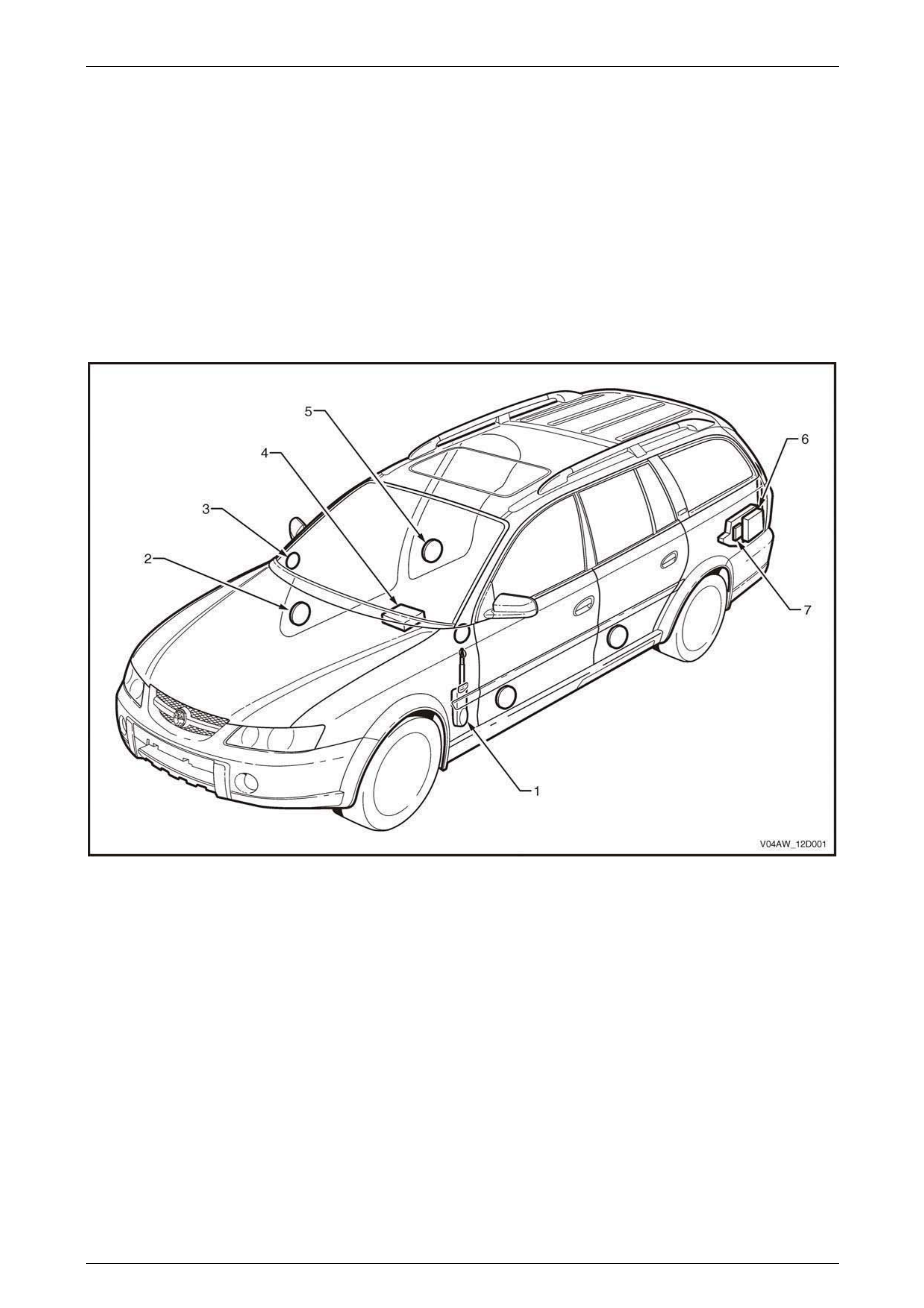
compartment. Figure 12D – 1 shows the location of the various components of the audio system.
For all other information relating to the entertainm ent system as fitted to MY 2004 AWD Wagon vehicles, refer to
Section 12D Entertainment System in the MY 2004 VY and V2 Series Service Information.
Figure 12D – 1
Legend
1 Height Adjustable Power Antenna 5 Rear Door Speaker
2 Front Door Speaker 6 Subwoofer (LX8 only)
3 Instrument Panel Tweeter Speaker 7 Amplifier (LX8 only)
4 Radio / CD Player (Audio head unit)
Page 12D–2

Entertainment System Page 12D–3
1.1 General Description
Two types of entertainment system systems are fitted to MY 2004 AWD Wagon vehicles and are as follows:
CX8 Model
CX8 model MY 2004 AWD Wagon vehicles are fitted with a system comprising of the following features:
• AM / FM 60 watt tuner
• Six disc CD changer in head unit
• Two tweeters mounted in the instrument panel
• Four door mounted speakers
• LCD display
• Speed sensitive radi o volume control
• Preset equaliser
• Height adjustable power antenna
Page 12D–3
Entertainment System Page 12D–4
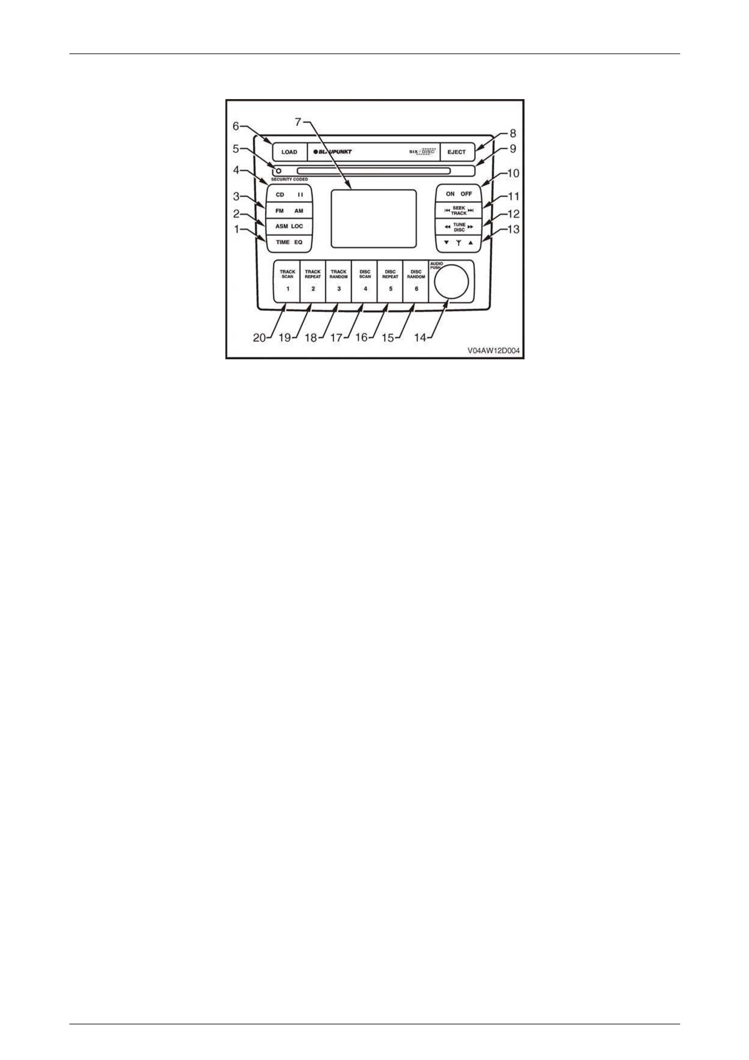
Figure 12D – 2 shows the radio / CD player fitted to CX8 model MY 2004 AWD Wagon vehicles.
Figure 12D – 2
Legend
1 Clock adjustment / Time display on/off
Equalizer On / Off setting
2 Automatic station memory storage
Local / distance search sensitivity
3 FM1 / FM2 / AM source button
4 CD source button
CD pause button
5 Security indicator light
CD Mode: Load, remove, wait indicator
6 CD load button
7 Information display
8 CD eject button
9 Disc load / remove slot
10 Radio On / Off
11 Radio Mode: Station seek
CD Mode: Track up / down
CD Mode: Push and hold: Track cue / review (Systems with
adjustable height electric antenna)
12 Radio Mode: Manual frequency select
CD Mode: Disc select
13 Electric antenna height adjustment (Systems with adjustable
height electric antenna)
CD Mode: Track cue / review (Systems without adjustable
height electric antenna)
14 Volume control
Push: Bass / Treble / Fader / Balance
15 CD Mode: CD Random
CD Mode: Disc 6 select
Radio Mode: Memory preset station 6
16 CD Mode: CD Repeat
CD Mode: Disc 5 select
Radio Mode: Memory preset station 5
17 CD Mode: CD Scan
CD Mode: Disc 4 select
Radio Mode: Memory preset station 4
18 CD Mode: Track Random
CD Mode: Disc 3 select
Radio Mode: Memory preset station 3
19 CD Mode: Track Repeat
CD Mode: Disc 2 select
Radio Mode: Memory preset station 2
20 CD Mode: Track Scan
CD Mode: Disc 1 select
Radio Mode: Memory preset station 1
Page 12D–4

Entertainment System Page 12D–5
LX8 Model
LX8 model MY 2004 AWD Wagon vehicles are fitted with a system comprising of the following features:
• AM / FM 200 watt tuner
• Six disc CD changer in head unit
• Priority key operation
• Two tweeters mounted in the instrument panel
• Four door mounted speakers
• One rear mounted subwoofer speak er
• Subwoofer amplifier
• Dot Matrix LCD display
• Speed sensitive radi o volume control
• Height adjustable power antenna
• Preset equaliser
• Dynamic Distortion Limiter
Page 12D–5
Entertainment System Page 12D–6
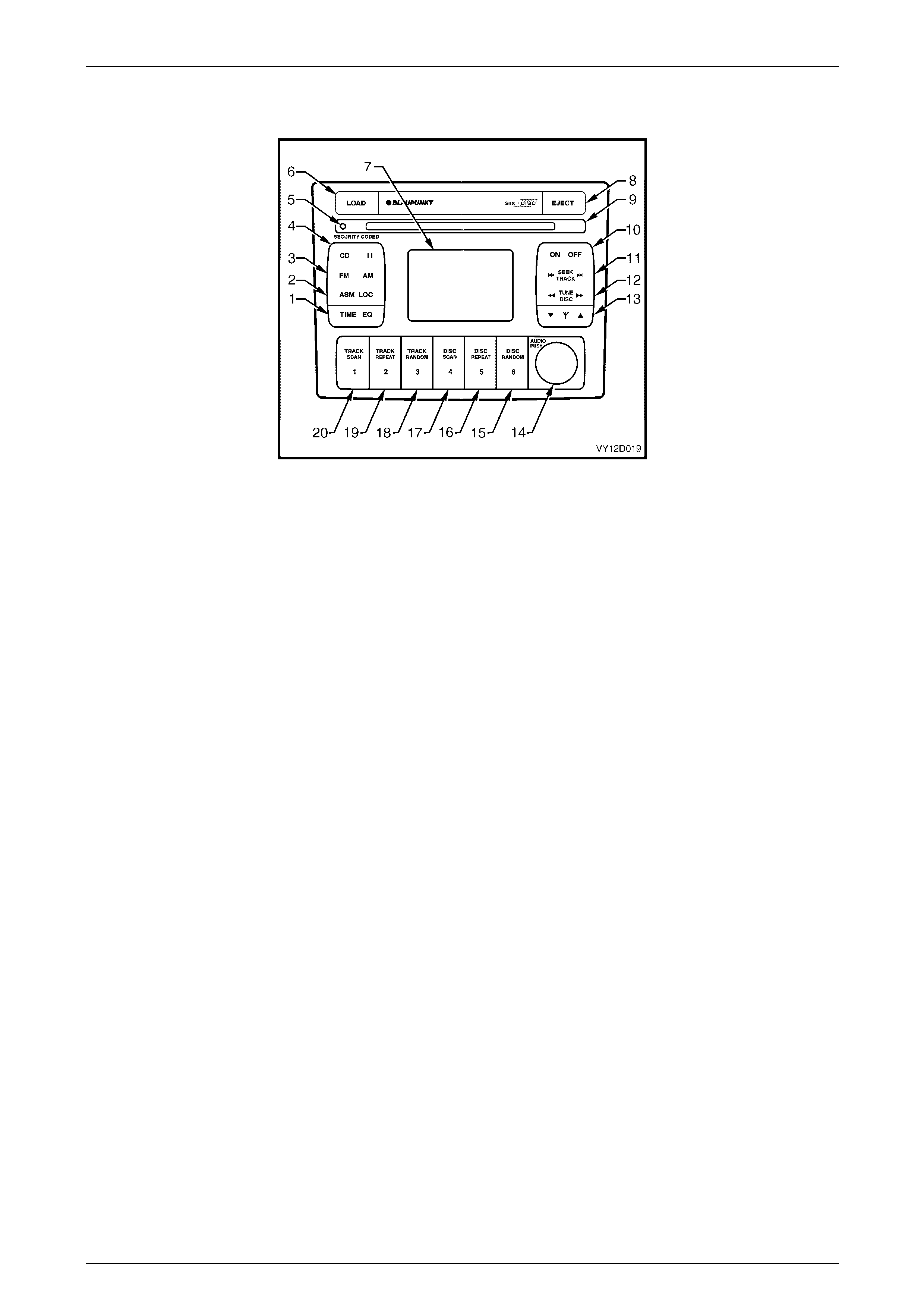
Figure 12D – 3 shows the 200 watt radio / CD player with height adjustable power antenna fitted to LX8 model MY 2004
AWD Wagon vehicles.
Figure 12D – 3
Legend
1 Clock adjustment / Time display on/off
Equalizer On / Off setting
2 Automatic station memory storage
Local / distance search sensitivity
3 FM1 / FM2 / AM source button
4 CD source button
CD pause button
5 Security indicator light
CD Mode: Load, remove, wait indicator
6 CD load button
7 Information display
8 CD eject button
9 Disc load / remove slot
10 Radio On / Off
11 Radio Mode: Station seek
CD Mode: Track up / down
CD Mode: Push and hold: Track cue / review
12 Radio Mode: Manual frequency select
CD Mode: Disc select
13 Electric antenna height adjustment
14 Volume control
Push: Bass / Treble / Fader / Balance / Loudness
adjustment
15 CD Mode: CD Random
CD Mode: Disc 6 select
Radio Mode: Memory preset station 6
16 CD Mode: CD Repeat
CD Mode: Disc 5 select
Radio Mode: Memory preset station 5
17 CD Mode: CD Scan
CD Mode: Disc 4 select
Radio Mode: Memory preset station 4
18 CD Mode: Track Random
CD Mode: Disc 3 select
Radio Mode: Memory preset station 3
19 CD Mode: Track Repeat
CD Mode: Disc 2 select
Radio Mode: Memory preset station 2
20 CD Mode: Track Scan
CD Mode: Disc 1 select
Radio Mode: Memory preset station 1
Amplifier and Subwoofer
An additional amplifier is fitted to the LX8 model to drive the subwoofer speaker. It is mounted to the left-hand side
quarter inner panel. T he amplifier is located behind left-hand side quarter inner panel, forward of the su bwoofer.
Page 12D–6
Entertainment System Page 12D–7
2 Service Operations
ATTENTION
All fasteners are important attaching parts as they affect the performance of vital components and / or could
result in major repair expense. W here specified in this section, fasteners MUST be replaced w ith parts of the
same part number or a GM approved equivalent. Do not use fasteners of an inferior quality or substitute
design.
Torque values must be used as specified during reassembly to ensure proper retention of all components.
Throughout this section, fastener torque wrench specifications may be accompanied with the following
identification marks:
Fasteners must be repl aced after loosening.
Vehicle must be at kerb height before final tightening.
Fasteners either ha ve micro encapsu lated sealant ap plied or in corporate a mech anical thread lo ck and
should only be re-used once. If in doubt, replacement is recommended.
If one of these identification marks is present alongside a fastener torque wrench specification, the
recommendation regarding that fastener must be adhered to.
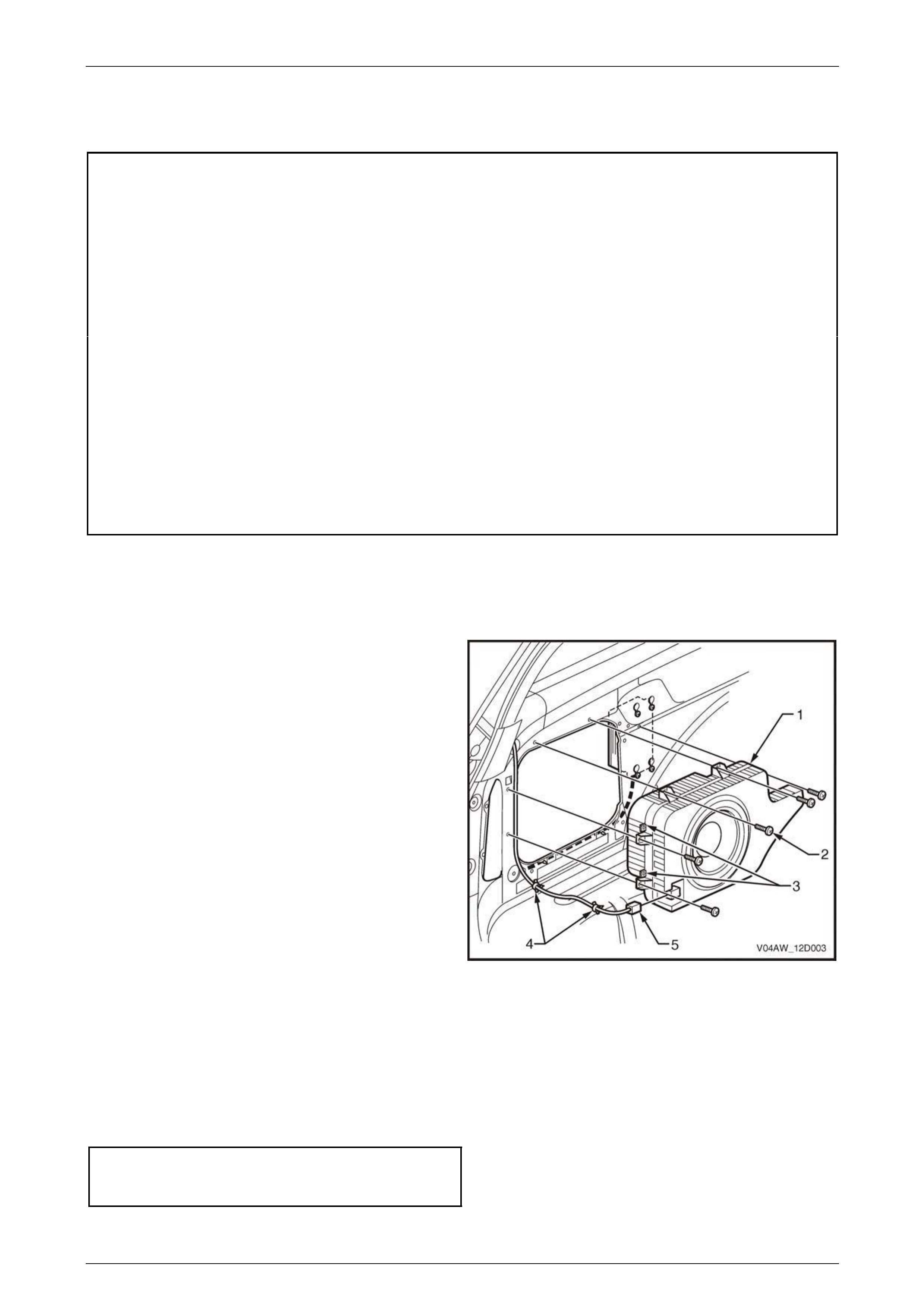
2.1 Subwoofer Speaker
Remove
1 Remove the left-hand side quarter inner trim panel
assembly. Refer to Section 1A8 Headlining and
Interior Trim.
2 Remove the five attaching bolts (2) from the
subwoofer speaker (1).
3 Unclip the wiring harness (4) from the mounting lugs
(3).
4 Disconnect the connector (5) from the subwoofer
speaker.
Figure 12D – 4
Reinstall
Installation of the subwoofer speaker is the reverse of the removal proce dure, noting the following:
1 Tighten the subwoofer speak er attachin g bolts (2) to the correct torque specification.
Subwoofer Speaker
Attaching Bolt
Torque Specification ..................................1.5 – 3.0 N.m
Page 12D–7
Entertainment System Page 12D–8
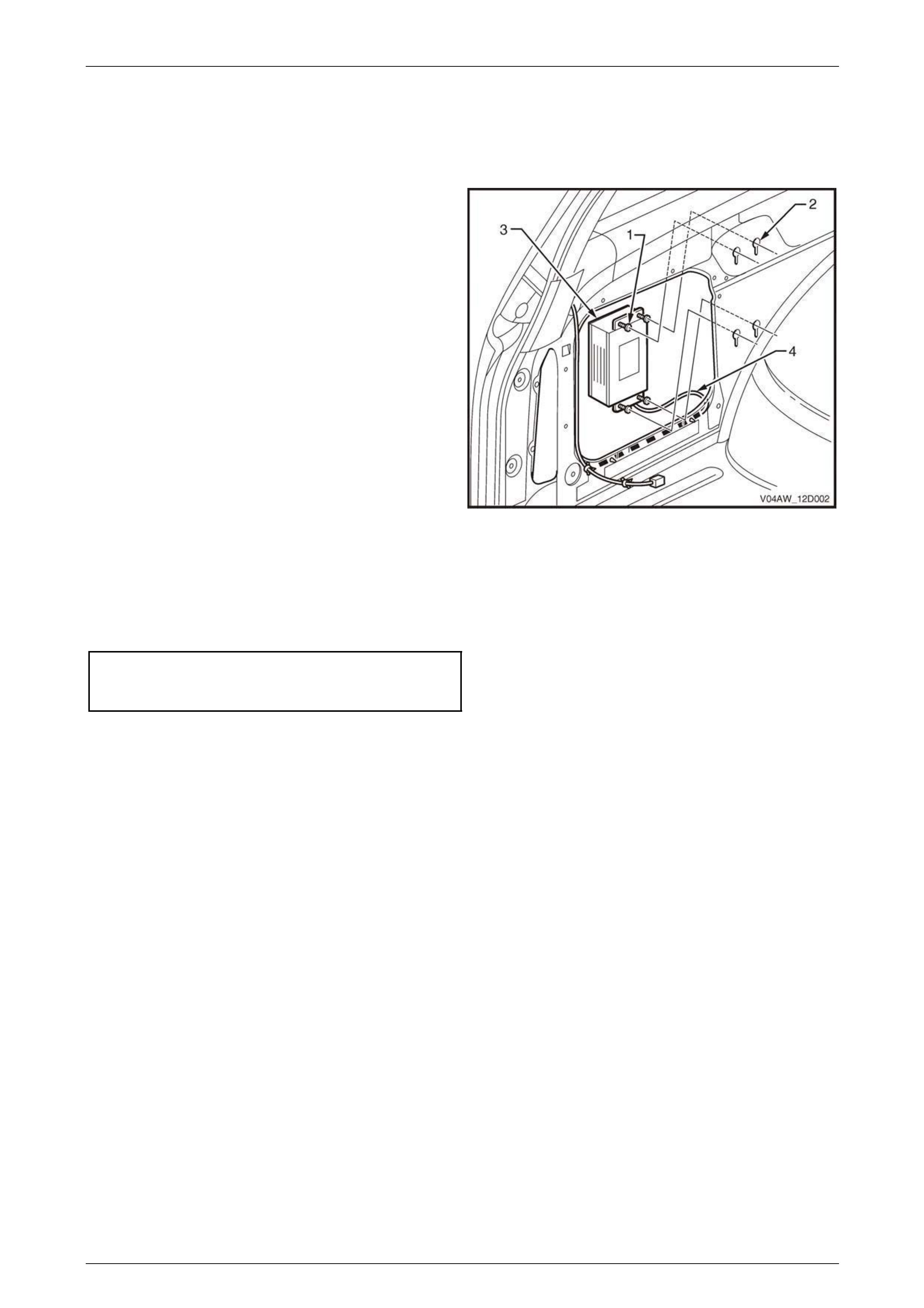
2.2 Subwoofer Amplifier
Remove
1 Remove the subwoofer speaker. Refer to
2.1 Subwoofer Speaker in this Section.
2 Loosen the screws (1) in the key-hole slots (2).
3 Slide the subwoofer amplifier (3) up and back and lift it
clear of the body panel.
4 Disconnect the connector (4) from the subwoofer
amplifier.
Figure 12D – 5
Reinstall
Installation of the subwoofer amplifier is the reverse of the removal procedure, noting the following:
1 Tighten the subwoofer amplifier retaining screws (1) to the correct torque specification.
Subwoofer Amplifier
Retaining Screw
Torque Specification ..................................1.0 – 3.0 N.m
Page 12D–8
Entertainment System Page 12D–9
3 Diagnostics
MY 2004 All Wheel Drive Wagon Entertainment System TECH 2 test mode and display i nformatio n carries over from
MY 2003 VY and V2 Series vehicles with the exception that the 2004 Mod el Year must b e selecte d from the vehicle
identification menu.
Main Menu
Turn the ignition on and press the power button (PWR) on
the TECH 2.
The TECH 2 will perform a series of self-diagnosing power
on self-tests (POST). Once this has been completed
successfully, the TECH 2 startup screen will be displayed.
Press the Enter key to continue.
The Main Menu screen is dis played.
Press the F0 function button or Select F0: Diagnostics by
using the arrow keys until F0: Diagnostics is highlighted and
press the Enter key.
VY12D050
Main Menu
F0:
F1:
F2:
F3:
F4:
Diagnostics
Service Programm ing System (SPS)
View Capture Data
Tool Options
Download/Upload Help
Figure 12D – 6
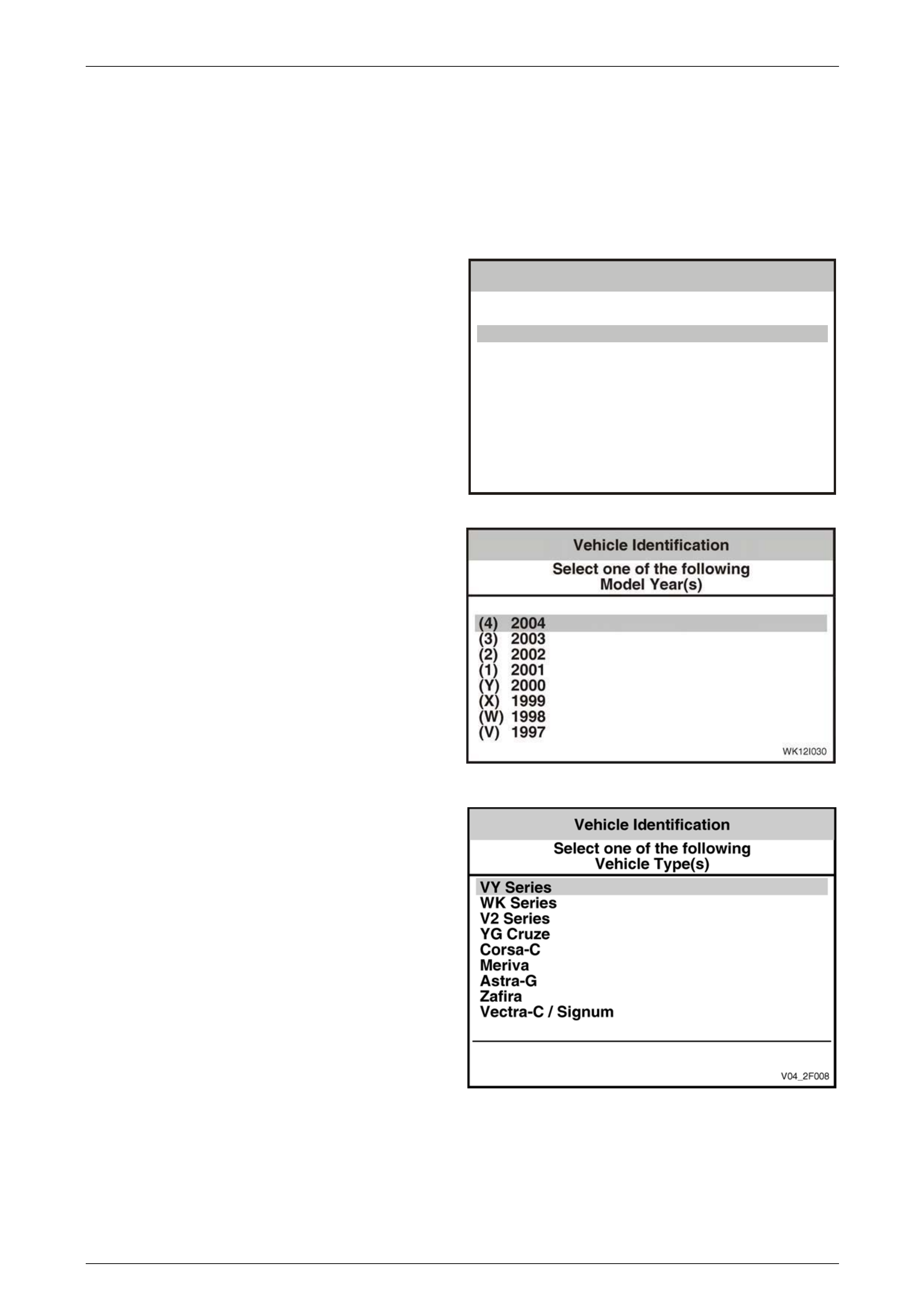
Model Year
Select 2004 from the Model Year list and press Enter.
Figure 12D – 7
The Vehicle Type selection is VY Series.
Figure 12D – 8
Page 12D–9
Entertainment System Page 12D–10
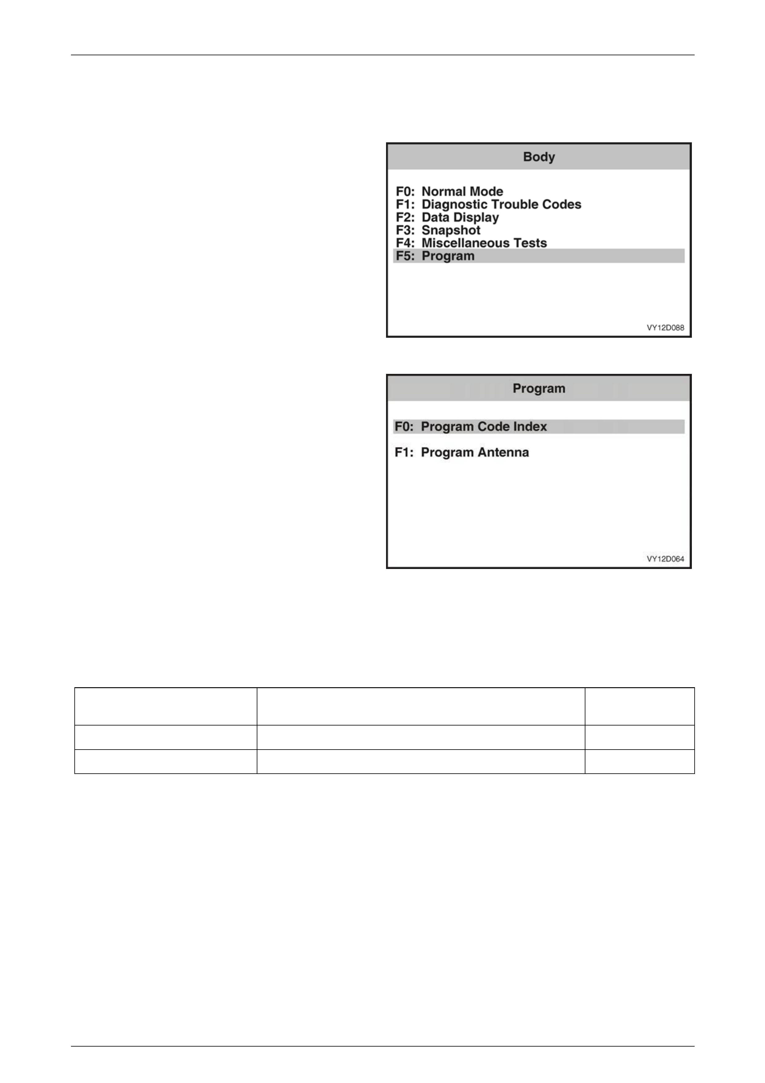
3.1 Program – Audio System
The Program function allo ws various Audio System parameters to be programmed.
1 From the Body Menu select F5: Program and press
the Enter key.
Figure 12D – 9
2 Using the TECH 2 Up and Down arrows, select the
required item and then press the Enter key.
Figure 12D – 10
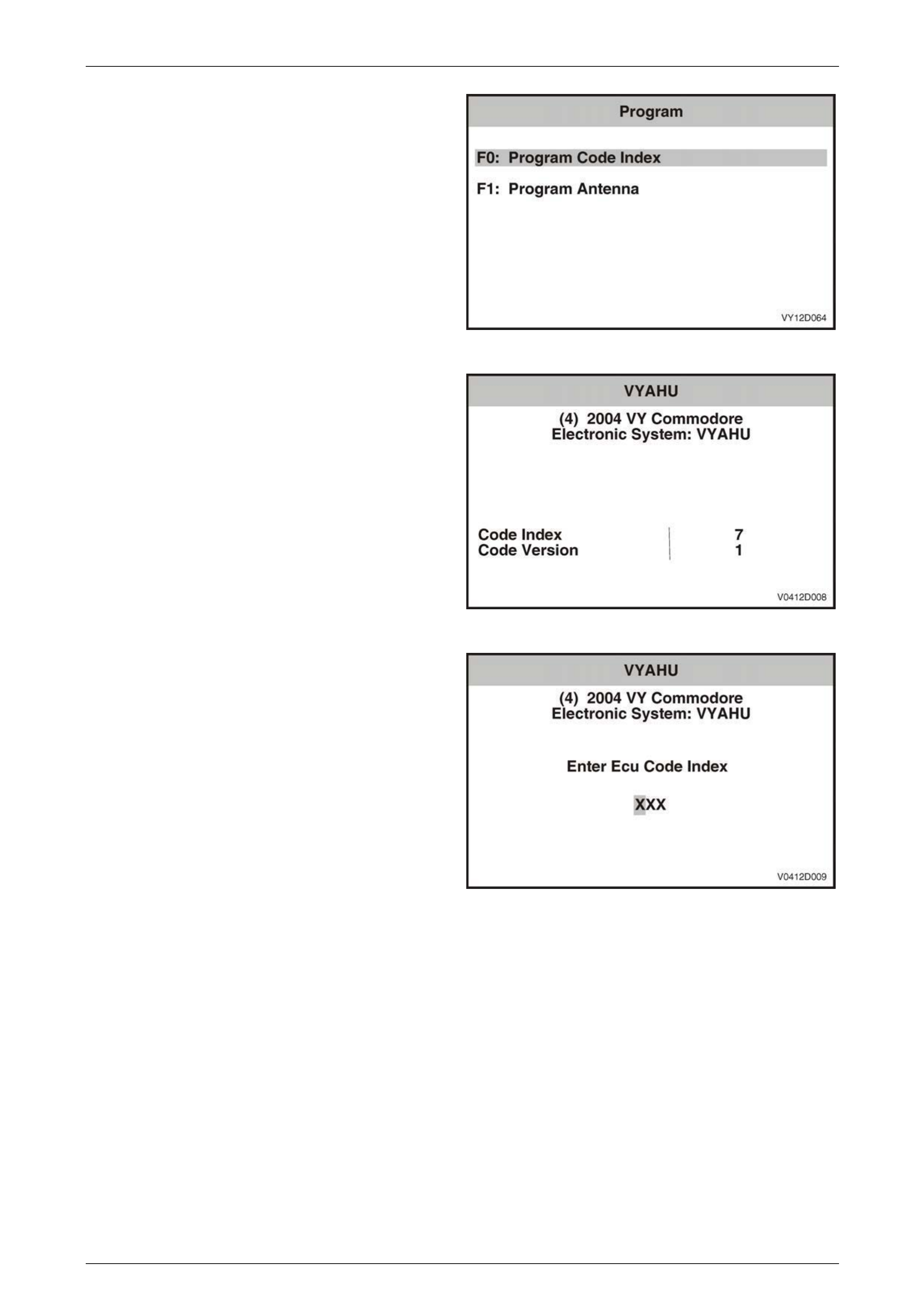
F0: Program Code Index
The Code Index number i dentifies the audio system and vehicle c onfiguration, and the Code Version n umber identifies
the software version. Only the Code Index nu m ber can be changed. The following table details the Code Index numbers
for the various models in the MY 2004 All W heel Drive Wagon vehicles.
Vehicle Audio System
Code Index
Number
CX8 AWD Wagon System 3 007
LX8 AWD Wagon System 4 007
Page 12D–10
Entertainment System Page 12D–11
1 From the Program Menu select F 0: Program Code
Index and press the Enter key.
Figure 12D – 11
2 The Code Index number a nd the Code Version
number are displayed. To change the Code Index
number, press the Program soft key. To exit without
making a change, press the Okay soft key.
Figure 12D – 12
3 Enter the three-digit Code Index number, including
leading zeros, using the num eral keys on TECH 2.
4 Press the Enter key to continue, or the Exit key to exit
without making a change.
5 Follow any TECH 2 scree n prompts when
programming is completed.
Figure 12D – 13
Page 12D–11
Entertainment System Page 12D–12
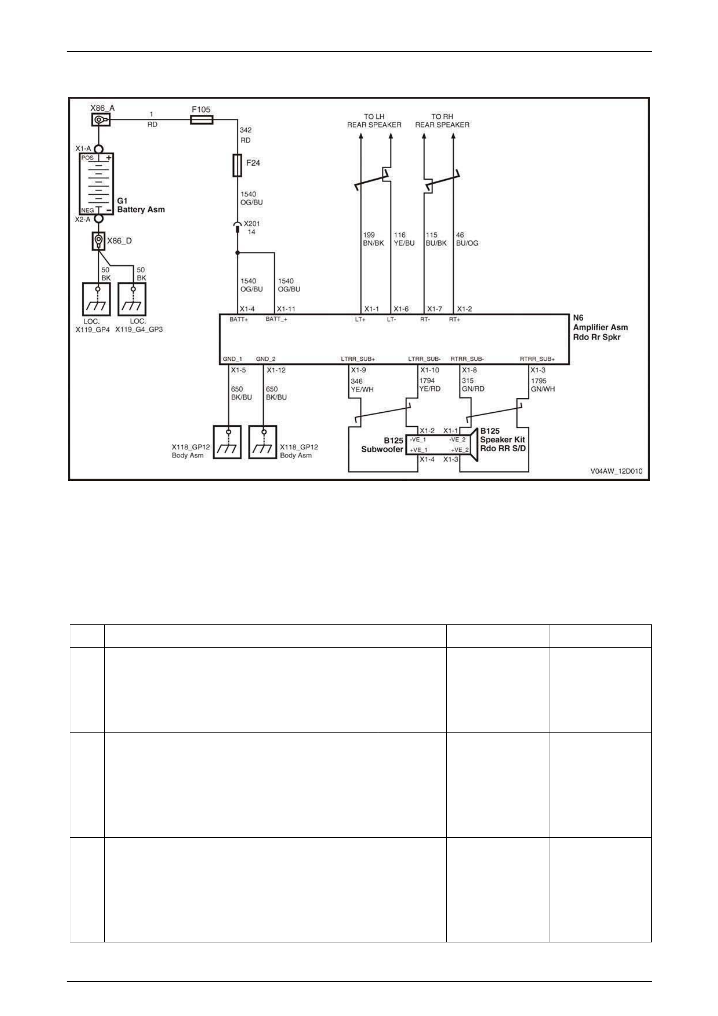
3.2 Subwoofer Amplifier
Figure 12D – 14
High level models are fitted with an auxi liary amplifier to improve the low frequenc y output of the system using a
subwoofer speaker mounted to the left-ha nd side quarter inner panel. The unit is a two channel, high powered design
that features self-protection circuitry to stop overload in the event of damage to wiring or speakers, or high temperatures.
Signal inputs to the amplifier are taken from the corresponding left and right rear door speakers, as per the system
diagram. The signals are then combined to produce a mono output. A 10 Amp fuse is mounted in th e end of the unit to
protect the wiring in the event of an internal amplifier failure.
Subwoofer Amplifier Diagnostic Ch art
Step Action Value(s) Yes No
1 Was the Diagnostic Circuit Check performed? Go to Step 2. Go to Diagnostic
Circuit Check in
Section 12D, 3.12 of
the MY 2003 VY
and V2 Series
Service Information.
2 Switch the audio system on, increase bass to
maximum, fade speakers to the rear, set balance to
STD, and adjust the volume to a medi um level.
Can you hear the subwoofer system operating from
inside the vehicle.
Go to Step 7. Go to Step 3.
3 Are the corresponding rear door speakers operati ng? Go to Step 5. Go to Step 4.
4 Check the door speaker wiring for an open circuit or
short circuit and repair as necessary. Refer to No
Sound or Distorted Sound Diagnostic Chart in the
MY2004 VY and V2 Series Service Information.
Test the audio system again as detailed in Step 2.
Is the system working?
Return audio
system settings to
normal. Go to
Step 10.
Go to Step 5.
Page 12D–12

Entertainment System Page 12D–13
Step Action Value(s) Yes No
5 Remove the subwoofer amplifier, refer to 2.2 Sub woofer
Amplifier in this Section.
Check the 10 A fuse located at end of the unit. Replace
if necessary.
Check the wiring connection on the subwoofer amplifier
wiring harness. Repair as necessary.
Using a digital voltmeter, check for battery voltage
between the following terminals of amplifier connector
N6 and a known good gro und. Repair as necessary:
• Terminal X1-4, circuit 1540.
• Terminal X1-11, circuit 1540.
Using a digital ohmmeter, check for continuity between
a known good ground a nd the following terminals of
amplifier connector N6. Repair as necessary:
• Terminal X1-5, circuit 650.
• Terminal X1-12, circuit 650.
Install the amplifier (refer to 2.2 Subwoofer Amplifier in
this Section) and test the audio system again as
detailed in Step 2.
Is the system working?
End of diagnostics. Go to Step 6.
6 Check the wiring connections on the subwoofer speaker
for damage or incorrect connection. Repair as
necessary.
Using a digital ohmmeter, check for open circ uit
between the speaker circuits and a known good ground
at amplifier connector N6. Repair as necessar y.
Test the audio system again as detailed in Step 2.
Is the system working?
End of diagnostics. Go to Step 7.
7 Disconnect the subwoofer amplifier conn ector N6.
Ensure that the subwoofer speaker connector is firmly
connected to the speaker. Using a digital ohmmeter,
check for continuity between each of the speaker
circuits at amplifier connector N6.
• Left Signal – X1-9, circuit 346 and X1-10, circuit
1794.
• Right Signal – X1-3, circuit 17 95 and X1-8, circuit
315.
Is the value as specified?
Approximately
2 ohms Replace the
subwoofer amplifier.
Refer to
2.2 Subwoofer
Amplifier in this
Section.
Go to Step 8.
8 Disconnect the subwoofer speaker connector.
Using a digital ohmmeter, check for continuity between
the speaker terminals.
Is the value as specified?
Approximately
2 ohms Go to Step 9. Replace the
subwoofer speaker.
Refer to
2.1 Subwoofer
Speaker in this
Section.
9 Repair open or short circuit in speaker wiring circuits
346, 1794, 315 or 1795 as appropriate.
Install the amplifier and speaker and test the audio
system again as detailed in Step 2.
Is the system working?
End of diagnostics. Replace the
subwoofer amplifier.
Refer to
2.2 Subwoofer
Amplifier in this
Section.
Page 12D–13

Entertainment System Page 12D–14
Step Action Value(s) Yes No
10 Is speaker working free from unusual vibrations, buzzes
or distortion? Verify fault with
customer. Go to Step 11.
11 Check the speaker cone for foreign materials, such as
screws, stones or wiring.
Test the audio system again as detailed in Step 2.
Is the system working as expected?
End of diagnostics. Replace the
subwoofer speaker.
Refer to
2.1 Subwoofer
Speaker in this
Section.
WHEN ALL DIAGNOSIS AND REPAIRS ARE COMPLETED, VERIFY CORRECT OPERATION
Page 12D–14

Entertainment System Page 12D–15
4 Specifications
Code Index Numbers
For the MY 2004 All Wheel Drive Wagon code index specifications, refer to 3.2 Program – Audio System.
Audio System Specifications
CX8 AWD Wagon
System 3
Radio / CD Player.................................................. AM/FM Stereo Tuner / Six Disc CD Player
Power Output.............................................................................................................. 60 watts
Speakers
Type
– Instrument Panel mounted ......... Two speakers – instrument fascia mounted tweeters
– Front Door..................................Two speakers – front door trim mounted 150 mm full
range dual cone
Impedance – Instrument panel speakers ............................................................2 ohms
Impedance – Front door speakers .......................................................................4 ohms
LX8 AWD Wagon
System 4
Radio / CD Player..................................................... AM/FM Stereo Tuner / Single CD Player
Power Output.............................................................................................................120 watts
....................................................................................................Subwoofer Amplifier 70 watts
Speakers
Type
– Instrument Panel mounted ......... Two speakers – instrument fascia mounted tweeters
– Front Door..................................Two speakers – front door trim mounted 150 mm full
range dual cone
– Rear Door....................................Two speakers – rear door trim mounted 150 mm full
range dual cone
– Quarter inner trim panel ...........................One speaker – LHS quarter inner trim panel
mounted 200 mm subwoofer
Impedance – Instrument panel speakers and subwoofer speaker.......................2 ohms
Impedance – Front and rear door speakers.........................................................4 ohms
Page 12D–15

Entertainment System Page 12D–16
5 Torque Wrench Specifications
Subwoofer Speaker Attaching Bolt..................................................................... 1.5 – 3.0 N.m
Subwoofer Amplifier Retaining Screw................................................................. 1.0 – 3.0 N.m
Page 12D–16