
Reverse Park i ng Ai d Page 12F–1
Page 12F–1
Section 12F
Reverse Parking Aid
ATTENTION
Before performing any service operation or other procedure described in this Section, refer to Section 00
Warnings, Cautions and Notes for correct workshop practices with regard to safety and/or property damage.
1 General Information............................................................................................................................... 2
1.1 Components ...........................................................................................................................................................2
Rear Object Sensor Control Module and Speaker Module.................................................................................2
Rear Object Sensor Assembly..............................................................................................................................3
Wire Harness Routeing..........................................................................................................................................3
2 Service Operations................................................................................................................................ 5
2.1 Rear Object Sensor Control Module.....................................................................................................................5
Remove ...................................................................................................................................................................5
Reinstall ..................................................................................................................................................................5
2.2 Speaker Modul e......................................................................................................................................................6
Remove ...................................................................................................................................................................6
Reinstall ..................................................................................................................................................................6
2.3 Rear Object Sensor Assembly..............................................................................................................................7
Remove ...................................................................................................................................................................7
Reinstall ..................................................................................................................................................................8
3 Diagnostics............................................................................................................................................. 9
3.1 Description..............................................................................................................................................................9
3.2 Wiring Diagram.....................................................................................................................................................10
3.3 Connector Chart...................................................................................................................................................11
Techline
Reverse Park i ng Ai d Page 12F–2
Page 12F–2
1 General Information
With the following exceptions, MY 2004 VY AWD Wagon Reverse Parking Aid information carries over from MY 2004 VY
vehicles:
• The rear object sensor control module is located underneath the right-hand rear seat bolster assembly.
• The speaker module is located in the roof cavity under the headlining at the right-hand rear of the vehicle.
• New rear bumper fascia assembly.
• New rear object sensor housing.
• Revised body wiring harnesses and reverse parking aid harness.
For Reverse Parking Aid information not contained within this Section, refer to Section 12F Reverse Parking Aid in the
MY 2004 VY and V2 Series Service information.
1.1 Components
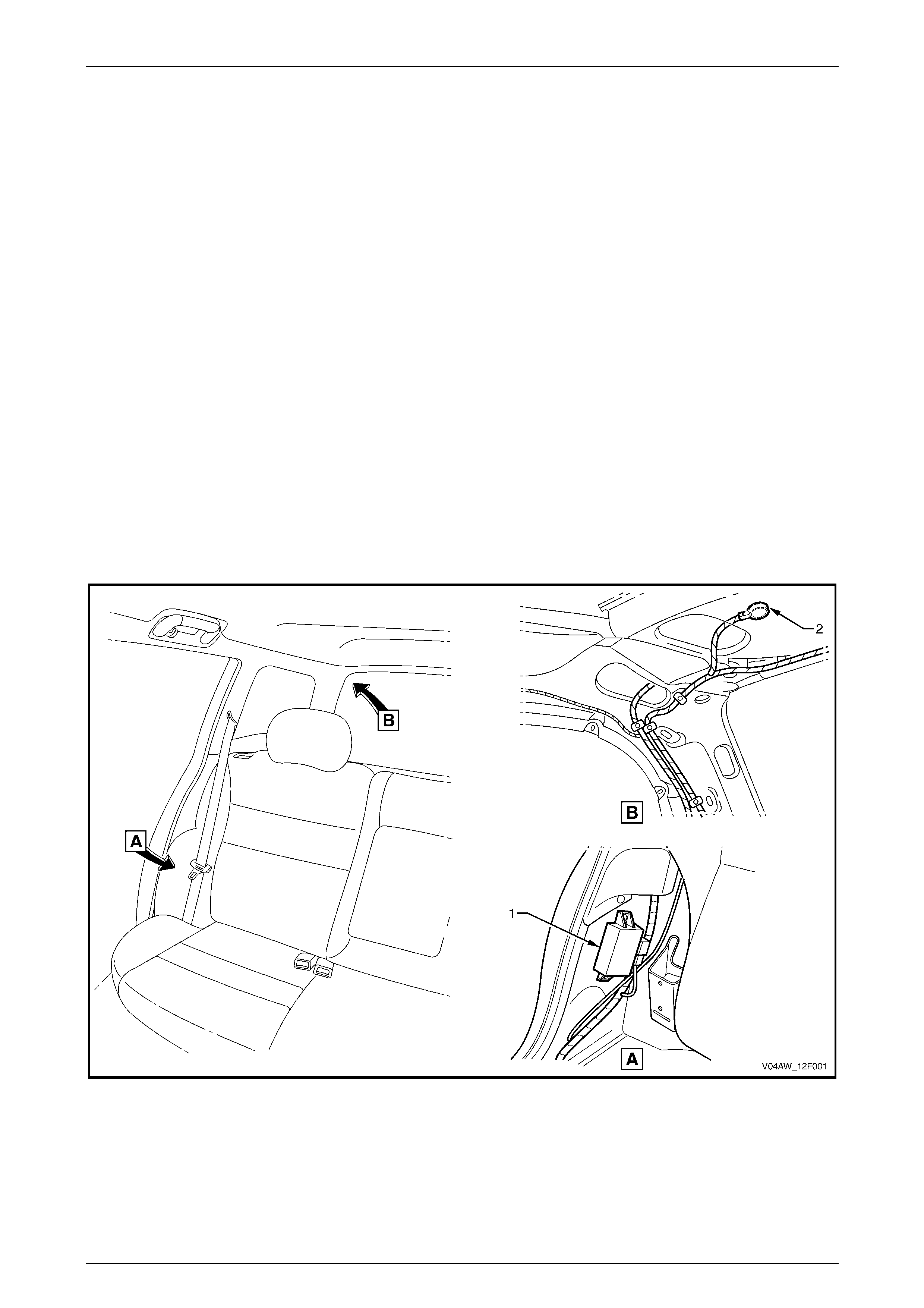
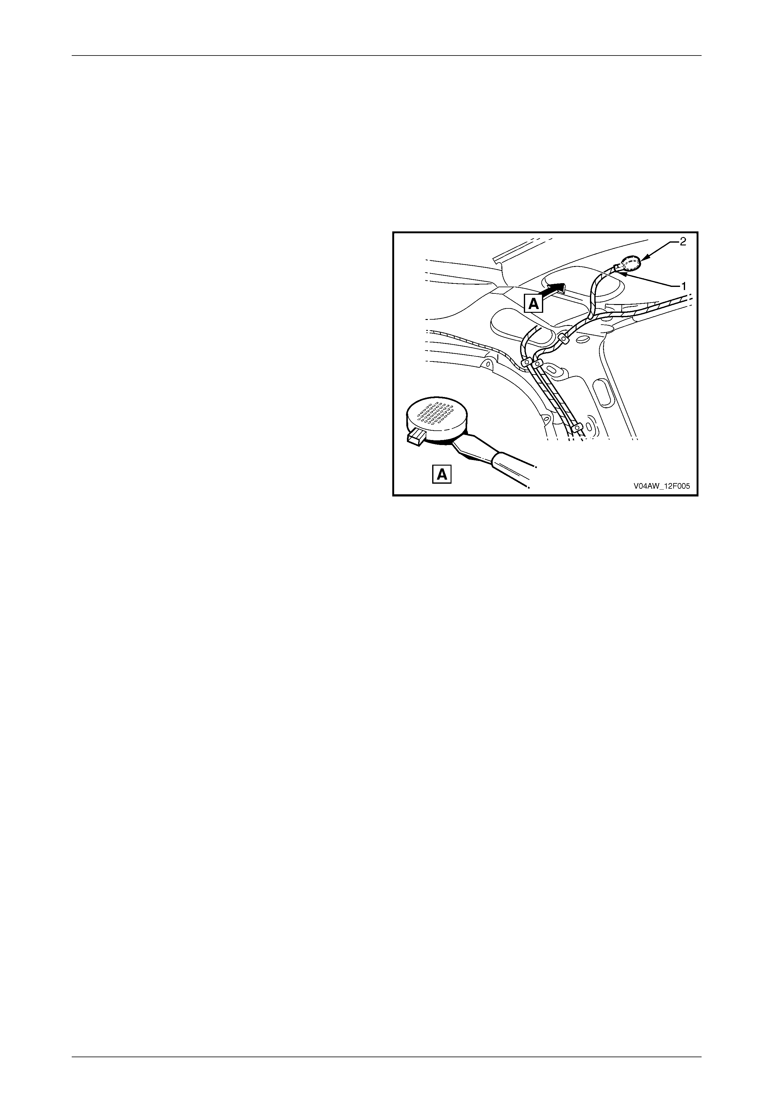
Rear Object Sensor Control Module and Speaker Module
The rear object sensor control module (1) is located underneath the right-hand rear seat bolster assembly, refer to Figure
12F – 1.
The speaker module (2) is located in the roof cavity under the headlining at the right-hand rear of the vehicle.
Figure 12F – 1
Legend
1 Rear Object Sensor Control Module 2 Speaker Module
Reverse Park i ng Ai d Page 12F–3
Page 12F–3
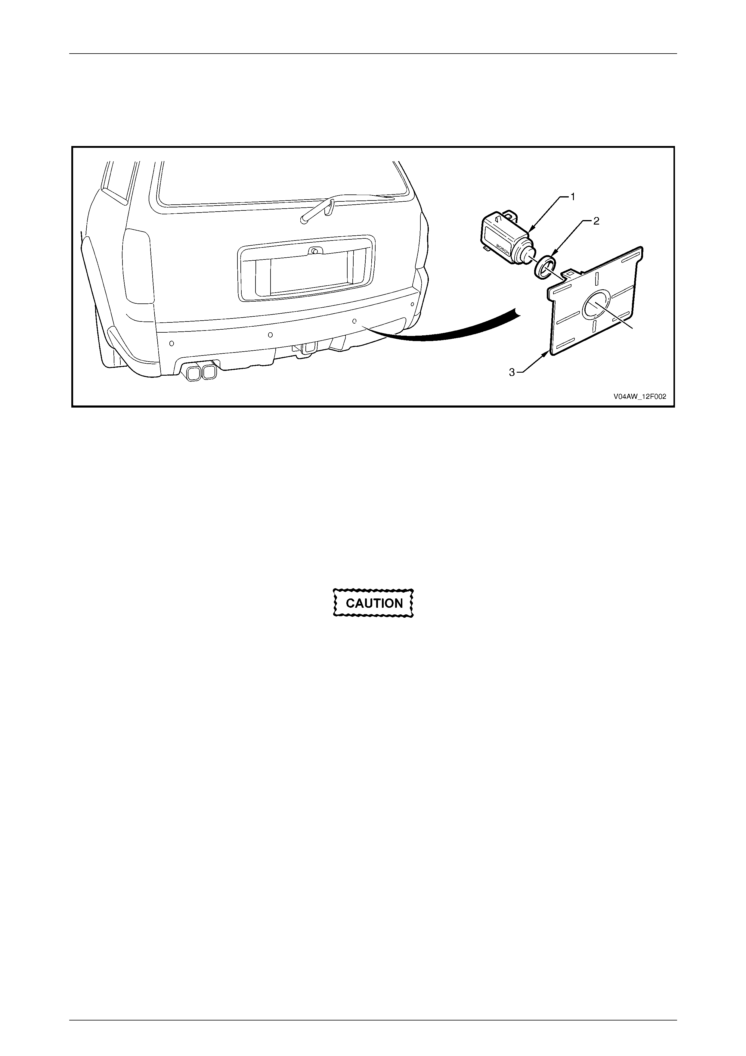
Rear Object Sensor Assembly
Each of the rear object sensor assemblies (1) is mounted in a rear object sensor housing (3), which is retained by clips to
the rear bumper fascia assembly. The rear object sensor housings allow for easy removal of the rear object sensor
assembly and the rear object sensor ring (2), refer to Figure 12F – 2.
Figure 12F – 2
Legend
1 Rear Object Sensor Assembl y (4 Places)
2 Rear Object Sensor Ring (4 Places) 3 Rear Object Sensor Housing (4 Places )
Each rear object sensor assembly operates as a transmitter and receiver of ultrasonic pulses and the exposed surface is
supplied painted in the vehicle's colour.
Replacement rear object sensor assemblies
are supplied pre-painted in the vehicle's body
colour. Do not apply further paint to the rear
object sensor assemblies, as it will have a
detrimental effect on the operation of the rear
object sensor assembli es.
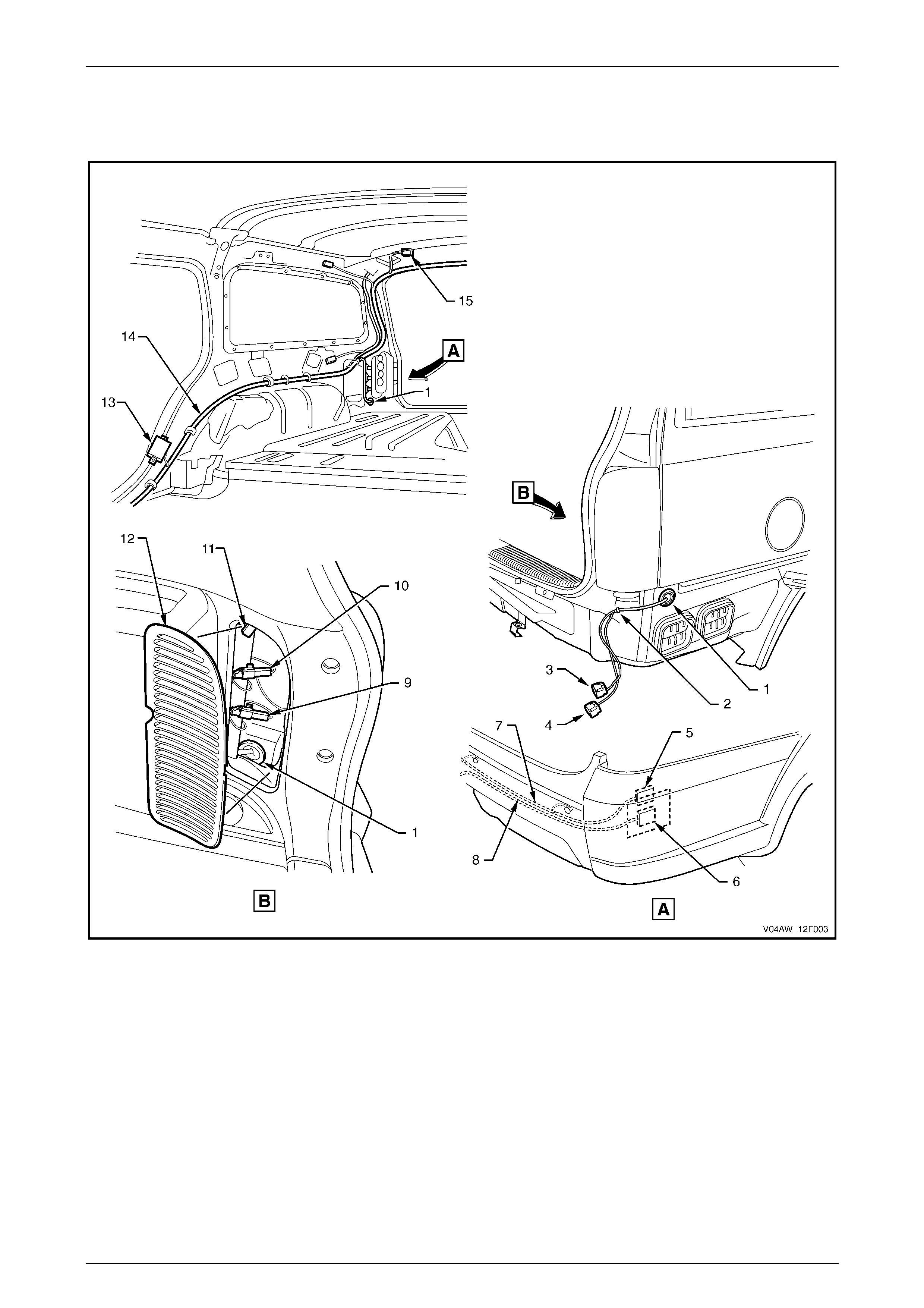
Wire Harness Routeing
The body wiring harness (14) is routed along the right-hand side of the vehicle, refer to Figure 12F – 3. The body wiring
harness passes through a grommet (1) to the outside of the vehicle and is connected to the reverse parking aid
harness (7) using connector X905 (3 and 5). The reverse parking aid harness is routed across the inside of the rear
bumper fascia assembly, connecting the four rear object sensor assemblies.
The tow hook connector X906 (9) is used to determine if an offset is required for the tow bar.
• For a vehicle without a towbar, connector X906 is closed. While reversing, as the distance to the detected object
draws closer, the frequency of the intermittent tone from the speaker module increases until it becomes constant at
a distance of approximately 30 cm.
• For a vehicle fitted with a towbar, connector X906 is open. While reversing, as the distance to the detected object
draws closer, the frequency of the intermittent tone from the speaker module increases until it becomes constant at
a distance of approximately 45 cm.
A reed switch is located within the trailer socket X109 and is connected to the blac k trailer reed switch connector
X907 (10). When the cover of the trailer socket is closed, the reed switch opens and the reverse parking aid is active.
When a connector (i.e. trailer, caravan, bike carrier with lights) is inserted into the trailer socket, the reed switch closes
and the operation of the reverse parking aid is temporarily disabled.
Reverse Park i ng Ai d Page 12F–4
Page 12F–4
The reverse parking aid can also be disabled by disconnecting connector X907. In this instance, the presence or
absence of a connector in the trailer socket is ignored.
The diagnosis connector X156 (11) is located behind the right-hand quarter trim panel vent (12).
Figure 12F – 3
Legend
1 Grommet
2 Clip
3 Body Wiring Harness Connector (X905)
4 Body Wiring Harness Connector (X909)
5 Reverse Park i ng Ai d Harness Connect or (X905)
6 Trailer Harness Connec tor (X909)
7 Reverse Park i ng Aid Harness
8 Trailer Harness
9 Tow Hook Connector (X906 – White)
10 Trailer Reed Switch Connector (X907 – Black)
11 Diagnostic Connector (X156)
12 Right-hand Quarter Trim Panel Vent
13 Rear Object Sensor Control Module
14 Body Wiring Harness
15 Speaker Module
Reverse Park i ng Ai d Page 12F–5
Page 12F–5
2 Service Operations
2.1 Rear Object Sensor Control Module
LT Section – XX-XXX
Remove
1 Remove the right-hand rear seat bolster assembly, refer to Section 1A7 Seat Assemblies.
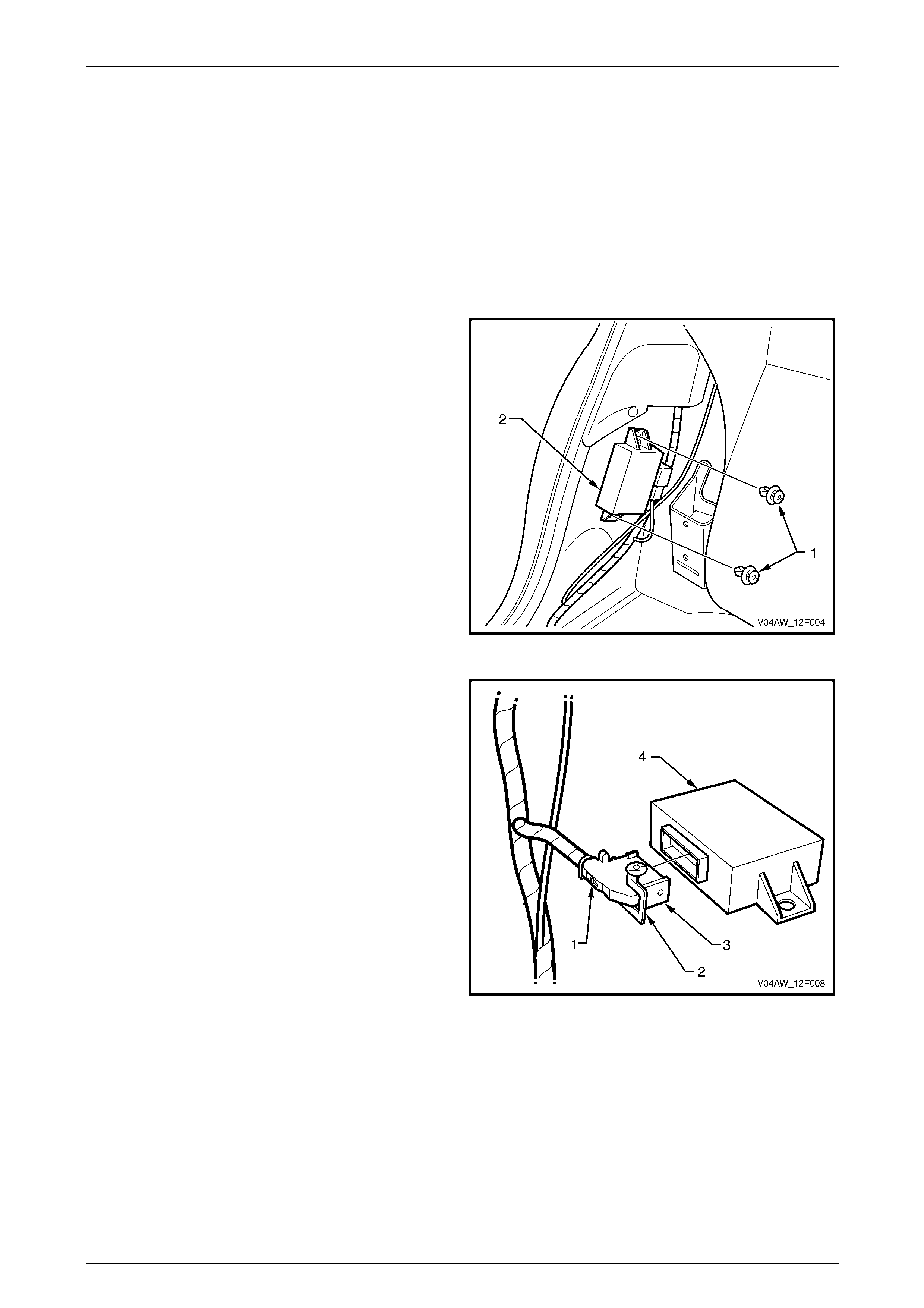
2 Remove the two retainers (1) attaching the rear object
sensor control module (2).
Figure 12F – 4
3 Press the tab (1) to unlock the connector lock
lever (2). Open the connector lock lever and rotate to
disconnect the connector (3) from the rear object
sensor control module (4).
Figure 12F – 5
Reinstall
Reinstallation of the rear object sensor control module is the reverse of the removal procedure, noting the following:
1 Ensure that the connector lock lever is secured by the tab.
Reverse Park i ng Ai d Page 12F–6
Page 12F–6
2.2 Speaker Module
LT Section – XX-XXX
Remove
1 Remove the right-hand rear of the headlining to gain access to the speaker module, refer to Section 1A8
Headlining and Interior Trim.
2 Remove the connector (1) from the speaker
module (2).
3 Using a knife or paint scraper, carefully prise the
speaker module from the roof cavity , separat ing the
double-sided tape.
Figure 12F – 6
Reinstall
Reinstallation of the speaker module is the reverse of the removal procedure, noting the following:
1 If reusing the speaker module, remove any remaining double-sided tape from the vehicle and the speaker module,
ensuring that the mating surfaces are clean. Apply new tape such as 3M 4428 or equivalent to the flat side of the
speaker module.
2 Peel the adhesive backing from the double-sided tape and affix the speaker module to the sheetmetal in the roof
cavity with the speaker vents pointing upwards.
Reverse Park i ng Ai d Page 12F–7
Page 12F–7
2.3 Rear Object Sensor Assembly
LT Section – XX-XXX
Remove
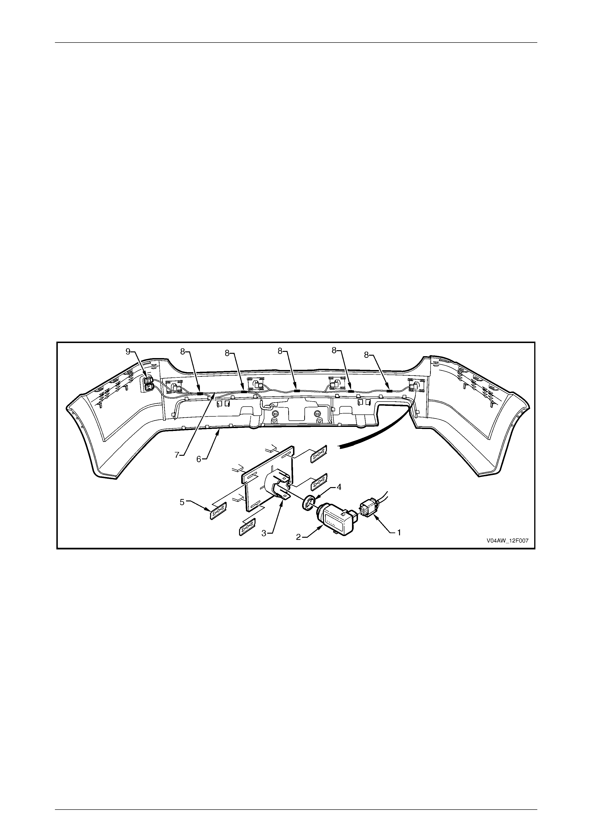
1 Remove the rear bumper fascia assembly, refer to Section 1D, 2.5 Rear Bumper Fascia Assembly.
2 For each rear object sensor assembly (2) that is to be remo ved, refer to Figure 12F – 7:
a Disconnect the rear object sensor connector (1) from the rear object sensor assembly.
b Prise the top and bottom tabs on the rear object sensor housing (3), and remove the rear object sensor
assembly and the rear object sensor ring (4).
c If required, remove the rear object sensor ring from the rear object sensor assembly.
3 If required, remove the reverse parking aid harness (7):
a Disconnect the rear object sensor connector from all rear object sensor assemblies.
b Prise the five clips (8) from the rear bumper fascia assembly.
c Unclip the reverse parking aid harness connector (9) from the rear bumper fascia assembly.
4 If required, remove the rear object sensor housings, refer to Section 1D, 2.5 Rear Bumper Fascia Assembly.
Figure 12F – 7
Legend
1 Rear Object Sensor Connector (B133) (4 P l aces)
2 Rear Object Sensor Assembl y (4 Places)
3 Rear Object Sensor Housing (4 Places )
4 Rear Object Sensor Ring (4 Places)
5 Retainer (16 Places)
6 Rear Bumper Fascia Assembl y
7 Reverse Park i ng Aid Harness
8 Clip
9 Reverse Park i ng Aid Harness Connector (X905)
Reverse Park i ng Ai d Page 12F–8
Page 12F–8
Reinstall
Replacement rear object sensor assemblies
are supplied pre-painted in the vehicle's bod y
colour. Do not apply further paint to the rear
object sensor assemblies, as it will have a
detrimental effect on the operation of the rear
object sensor assembli es.
The rear object sensor ring prevents
vibrations from the rear object sensor
assembly being transferred to the
surrounding components. Incorrect fitment
will change the characteristics of the rear
object sensor assembly.
Reinstallation of the rear object sensor assembly is the reverse of the removal procedure, noting the following:
1 Ensure that each rear object sensor ring is correctly seated on its rear object sensor assembly.
2 Ensure that each rear object sensor assembly is securely located in the rear object sensor housing with the
connector side facing towards the centreline of the vehicle.
3 Attach the reverse parking aid harness to the rear bumper fascia assembly by pressing each clip onto the
corresponding rib.

Reverse Park i ng Ai d Page 12F–9
Page 12F–9
3 Diagnostics
3.1 Description
Differences in the position of components and the circuit as compared to MY 2003 VY and V2 Series are:
• Routeing of the body wiring harness is on the right-hand si de of vehicle.
• The rear object sensor control module is lo cated underneath the right-hand rear seat bolster assembly.
• The speaker module is located in the roof cavity under the headlining at the right-hand rear of the vehicle.
• Connector X200 pin 2 has been changed to connector X201 pin 4.
The above changes in the circuit do not affect the diagnosis procedures.
Reverse Park i ng Ai d Page 12F–10
Page 12F–10
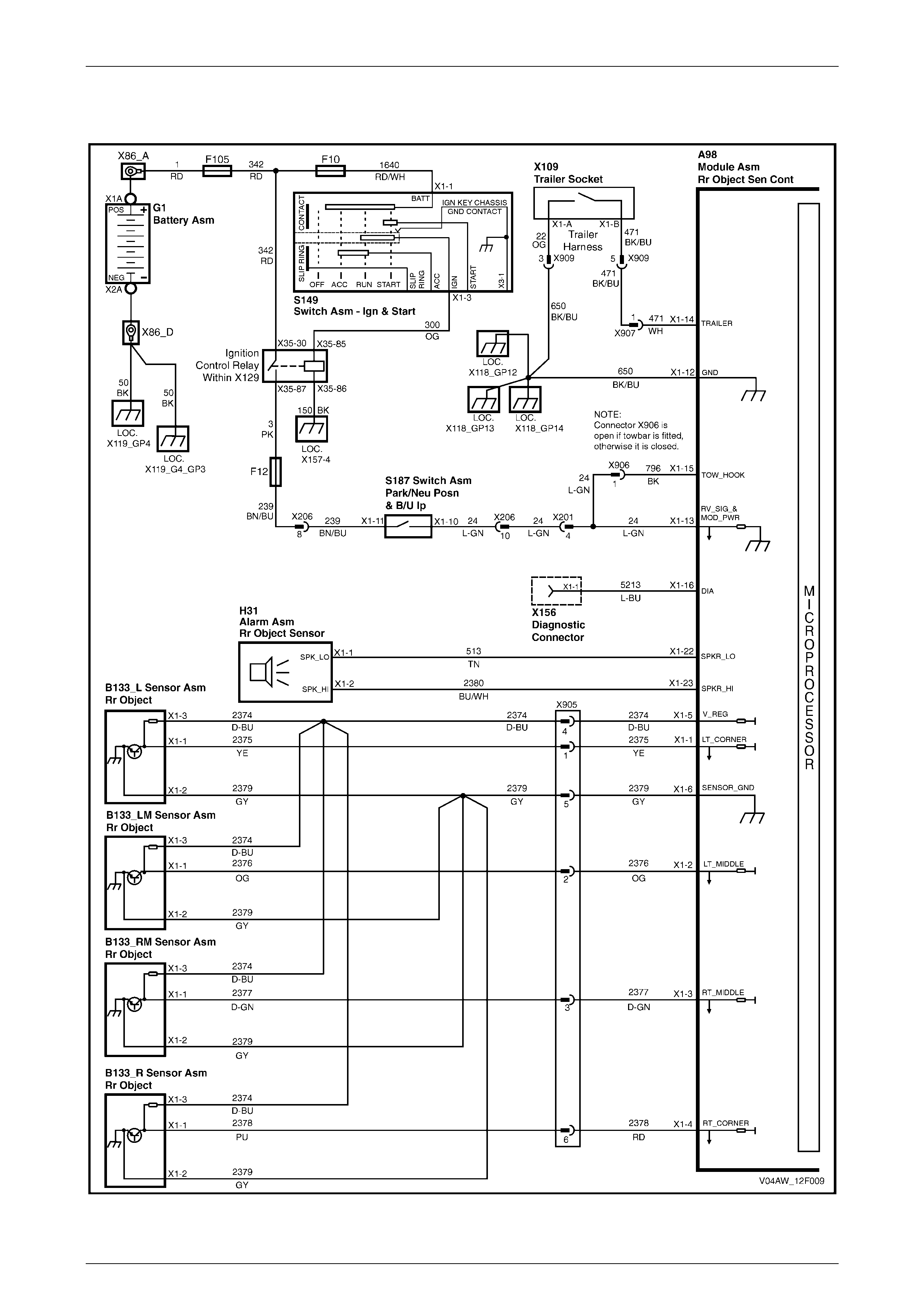
3.2 Wiring Diagram
Figure 12F – 8
Reverse Park i ng Ai d Page 12F–11
Page 12F–11
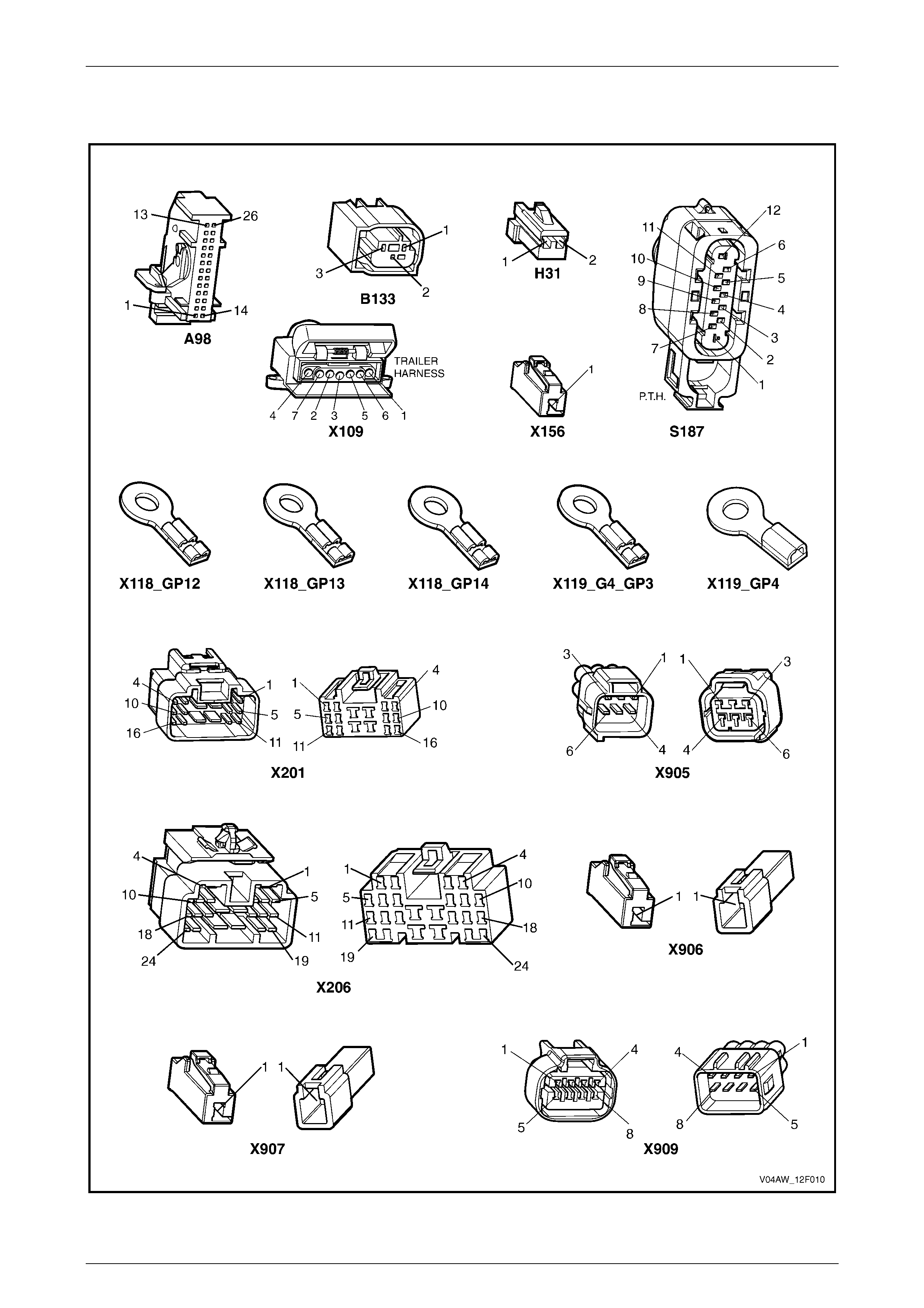
3.3 Connector Chart
Figure 12F – 9