Body Control Module 12J-1
Section 12J
Body Control Module
ATTENTION
Before performing any Service Operation or other procedure described in this Section, refer to Section 00
Warnings, Cautions and Notes for correct workshop practices with regard to safety and/or property damage.
1 General Information ...............................................................................................................................2
1.1 General Description............................................................................................................................................... 2
1.2 Rear Wiper Control................................................................................................................................................ 3
Rear Wiper Control Module................................................................................................................................... 4
Rear Wiper Control Module Connector .............................................................................................................. 4
Rear Wiper Control Module Connector Terminal Pin Allocations....................................................................... 5
1.3 Rear Window Latch Control.................................................................................................................................. 6
Latch Releasing Usin g the Remote Key .............................................................................................................. 6
Operation ........................................................................................................................................................... 7
Rear Latch Releasing using the Instrument Pane l Compartment Button ........................................................... 8
1.4 Instrumentation Illumination............................................................................................................................... 10
Inclinometer (P2) Control Illumination............................................................................................................... 10
Instrument Illumination System Checks ........................................................................................................... 10
2 Service Operations...............................................................................................................................12
3 Tech 2 Diagnosis for BCM...................................................................................................................13
4 BCM Diagnostics..................................................................................................................................14
4.1 Rear Window Latch System Diagnostics........................................................................................................... 14
Introduction.......................................................................................................................................................... 14
Rear Window Latch System Diagnostic Chart .................................................................................................. 15
5 Specifications.......................................................................................................................................21
Rear Wiper Control Module (A122)..................................................................................................................... 21
Page 12J-1
Techline
Techline
Techline
Techline
Techline
Techline

Body Control Module 12J-2
1 General Information
This Section provides information o n the Bod y Cont rol Module (BCM) fitted to MY 2004 AWD Wagon vehicles.
There are two levels of model in the MY 2004 AWD Wagon range in which two types of BC M are installed.
AWD Model BCM Level BCM Part Number
CX8 LUX 92155209
LX8 HIGH 92210259
1.1 General Description
The BCM functions and features are the same as those for the MY 2003 VY and V2 Series vehicles except for the
following changes:
• The Occupant Climate Control (OCC Auto A/C) system is fitted as standard equipment.
• An external Rear Wiper Control Module (A122) controls the overall operation of the rear wiper and rear window
latch systems. For further information, refer to Section 12N Wipers, Washers and Horn.
The rear window has a solenoid activated latch that enables the window to be opened only when the rea r wiper is
not operating.
• The inclinometer assembly fitted to the centre of the instrument panel has two lamps that illuminate the t wo
inclinometer gauges. These lamps are connected to the illuminati on dimming system controlled by the BCM.
• Both levels of MY 2004 AWD Wagon vehicles are fitted with triple window instrument clusters. The only difference
is in appearance.
For other information relating to instrumenta tion on MY 2004 AWD Wagon vehicles, refer to
Section 12C Instruments in the MY 2003 VY and V2 Series Service Information.
Selected BCM terminals have different functions in the MY 2004 AWD Wagon when compared to those in the MY 2003
VY and V2 Series Service Information.
The differences are outlined in the following chart.
BCM Terminal
Identifier Terminal Name Terminal
Acronym Description Action
X1-19 A/C AC_STAT Air conditioner on indicator LED. Occupant Climate Control
(OCC) system is used instead
of the BCM controls.
X1-18 DEFOG DFG_STAT Demist heater on indicator LED. Occupant Climate Control
(OCC) system is used instead
of the BCM controls.
X2-12 DFG DFG REQ Demist heater request switch. Occupant Climate Control
(OCC) system is used instead
of the BCM controls.
X2-12 Blower BLOWER
Monitoring of blower motor
switch. Occupant Climate Control
(OCC) system is used instead
of the BCM controls.
X1-7 Rear Wiper On RR_WWPR Activates the rear wiper motor. The wiper control now connects
to the wiper motor via the A122
Rear Wiper Control Module.
X3-7 Rear Wiper
Request RR_WWPR_R Rear wiper request comes from
the wiper stalk. The wiper control now connects
to the wiper motor via the A122
Rear Wiper Control Module.
Refer to Section 12J Body Control Module in the MY 2003 VY and V2 Series Service Information for further details about
the functions of the BCM.
Page 12J-2
Body Control Module 12J-3
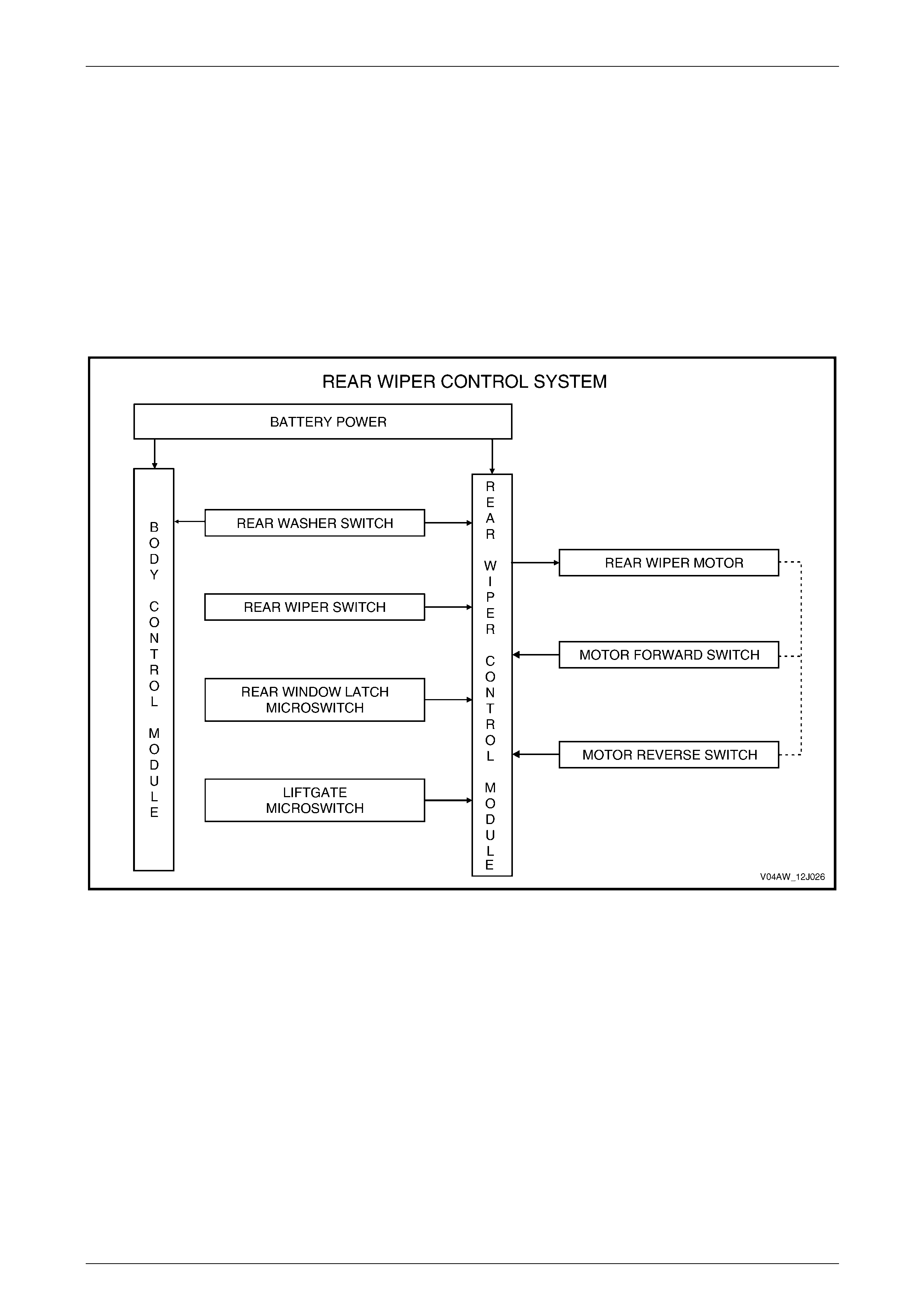
1.2 Rear Wiper Control
Unlike other wagon models in the VY Series, the BCM in the MY 2004 AWD Wagon does not monitor or control the re ar
wiper or washer system.
NOTE
All MY 2003 VY and V2 Series documentation
relating to the operation or testing of the Rear
Window Wiper and Rear Window Washer should
be disregarded.
Refer to Section 12N Wipers, Washers and Horn for further information regarding the rear wiper and control module
function and operation.
Figure 12J – 1
NOTE
If the rear wiper has been operating when the
ignition is switched off, the rear wiper arm may
remain on the rear window glass rather than in
the parked position. This will either restrict or
prevent the opening of the rear window from the
liftgate assembly.
This situation occurs due to power being
removed from the Accessories Relay, the Rear
Wiper Control Module (A122) and the wiper
motor when the ignition is switched off. To
overcome the situation, switch the ignition on,
turn the rear wiper off and allow it to fully park
(clear of the window).
Page 12J-3
Body Control Module 12J-4
Rear Wiper Control Module
Figure 12J – 2 shows the location of the rear wiper control
module (1) in the liftgate inne r panel.
The upper section of the dr awing shows the module located
in its fitted position. The lower section of the drawing
indicates how the module is remove d and installed.
For rear wiper control module removal and installation
details, refer to Section 12N Wiper / Washers & Horn.
Figure 12J –2
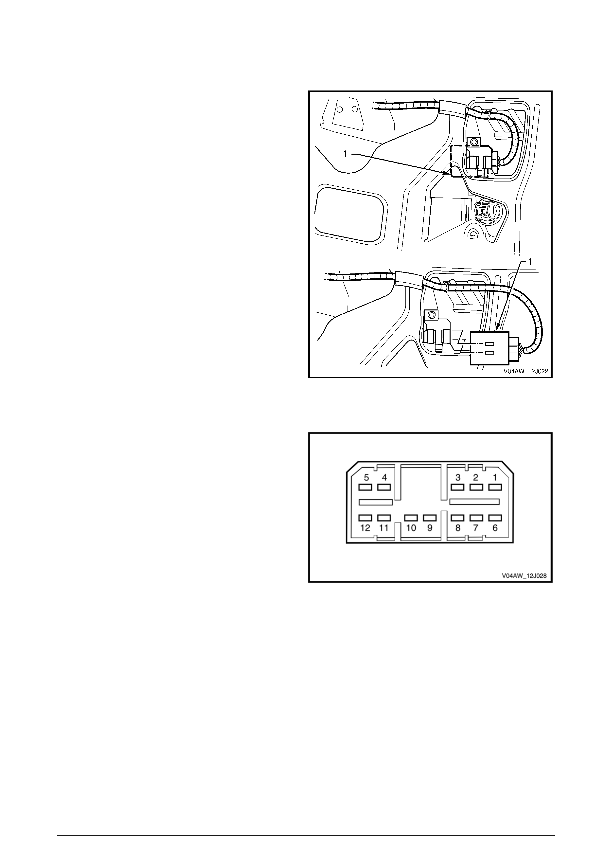
Rear Wiper Control Module Connector
Figure 12J – 3 illustrates the terminal assi gnment of the rear
window module connector.
Figure 12J – 3
Page 12J-4
Body Control Module 12J-5
Rear Wiper Control Module Connector Terminal Pin Allocations
A122 Connector X1
Pin No. Description Circuit Wire Colour Active
Signal Circuit
Type
X1–1 Battery main power (+) 243 BN/WH Always active P
X1–2 Power ground 650 BK/BU Always active GND
X1–3 Wiper switch input 391 GY/RD Switch to B+ PU
X1–4 Washer input 2270 L-GN Switch to B+ PU
X1–5 Rear wiper forward drive power 393 GY T oggles B+/GND O
X1–6 Rear wiper reverse drive power 392 D-GN Toggles GND/B+ O
X1–7 Motor park switch common input 2283 WH Always active GND
X1–8 Motor park switch FORWARD input 2269 GN Pull to GND I
X1–9 Motor park switch REVERSE input 5456 YE Pull to GND I
X1–10 Liftgate a nd rear window open switches 744 BK/GN Pull to GND I
X1–11 Rear window release signal from BCM 56 RD/GN Pull to B+ I
X1–12 Rear window release signal to Y7 actuator. 6188 TN/BK Pull to B+ O
Legend – Circuit Type
GND Earth P Power I Input
O Output PU Pull Up I/O Input / Output
Page 12J-5
Body Control Module 12J-6
1.3 Rear Window Latch Control
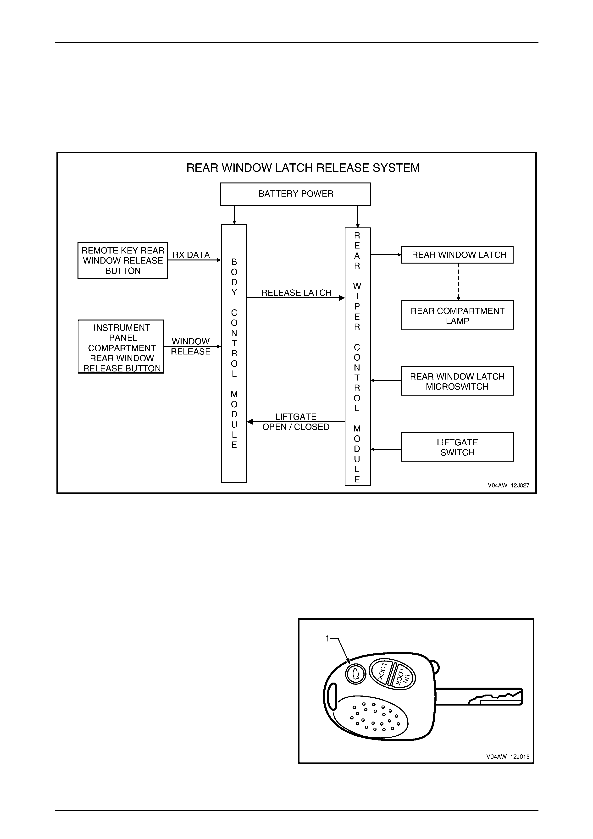
When the remote key button or the instrument panel compartment button is pressed, a signal is sent to the rear wiper
control module via the BCM, to trigger the rear window latch release. As the latch releases, the rear compartment
microswitch in the latch assembly (refer Figure 12J – 6) operates and the rear compartment lamp illuminates. W hen the
liftgate is open, a switch, also in the liftgate (refer Figure 12J – 7), signals the rear wiper control module to inhibit
operation of the rear wiper. Refer to Figure 1 2J – 1.
Figure 12J – 4
The rear window can be relea s ed from the liftgate by using the remote coded key rear window release button or the Rear
Window Release Button (S161) in the instrument panel compartment.
When the latch has been rel eased, the lower edge of the rear window separates from the liftgate rubber seal by
approximately one centimetre. Use the speci ally fitted lifting tab to lift the window further outwards. As the window is
lifted, two gas strut assemblies assist opening to the full y open position.
Latch Releasing Using the Remote Key
The rear window release button (VY Series sedan rear
compartment release button) (1) operates the Rear Windo w
Release Actuator Solenoid (Y7).
Figure 12J – 5
Page 12J-6
Body Control Module 12J-7
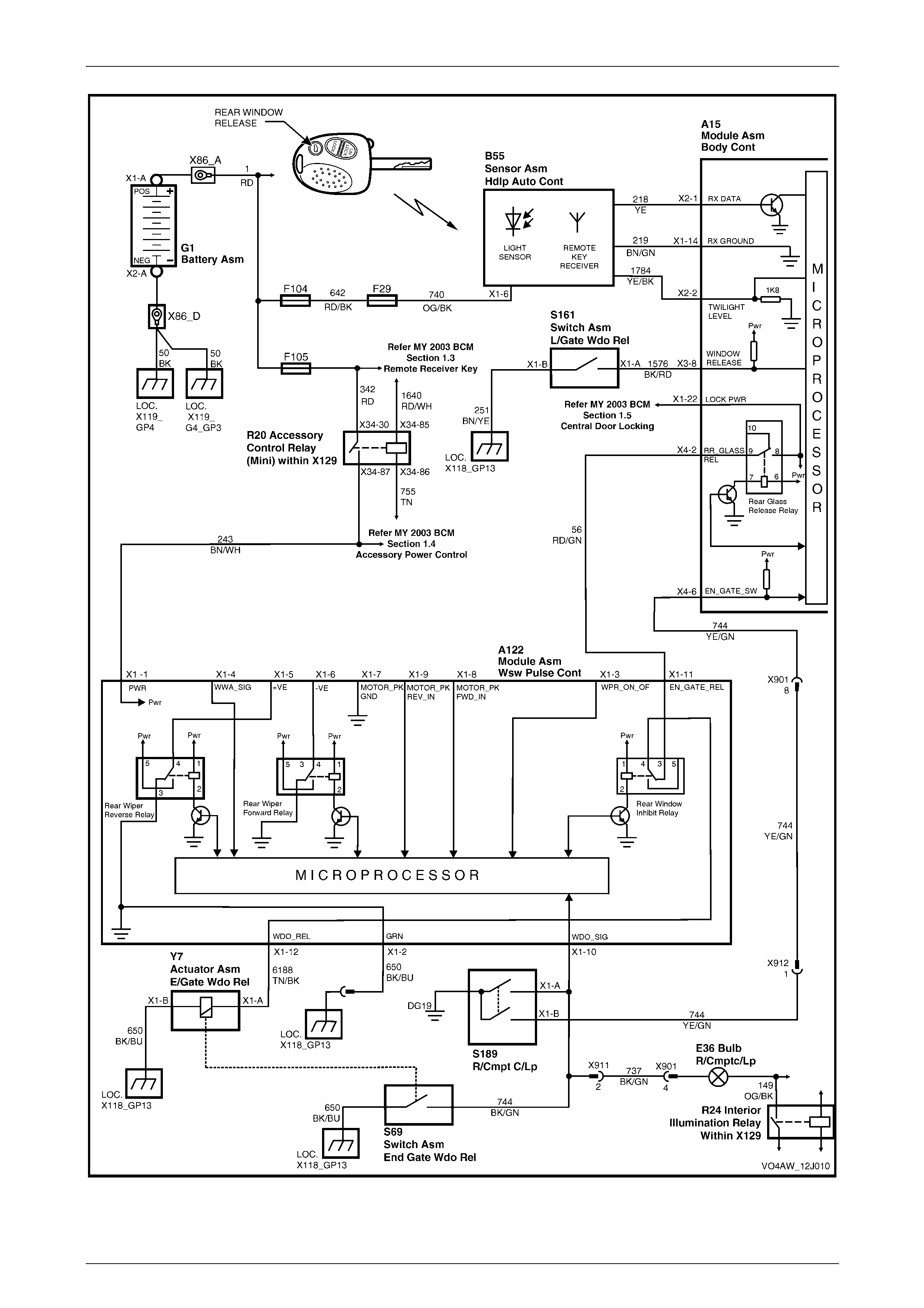
Operation
The BCM boot solenoid relay in the MY 2003 VY and V2 Series sedan models becomes th e rear window release relay in
the MY 2004 AWD Wagon. This operates the Rear W in dow Release Actuator Solenoid (Y7). Refer to Figure 12J – 9.
When the remote key rear windo w release b utton (1) is pre ssed, the remote control transmits a signal. When in range,
this signal is received by the Vehicle Sensor Unit (B55) and then transferred to BCM terminal X2-1. The BCM then
energises the internal rear gl ass release relay and battery voltag e is applied to BCM terminal X4-2.
Voltage is then applied via circuit 56 to the Rear Wiper Control Module (A122), terminal X1-11. If the rea r wiper control
switch has not been switched on, the A122 internal re ar window inhibit relay is de-energised. T his enables the voltage to
be applied to the solenoid (Y 7) via terminal X1-12.
The rear wiper inhibit rel ay is energised while the rear wiper switch is switched on. With the rear wiper inhibit relay in this
state, the rear window latch actuator solenoid (Y7) cannot be energised.
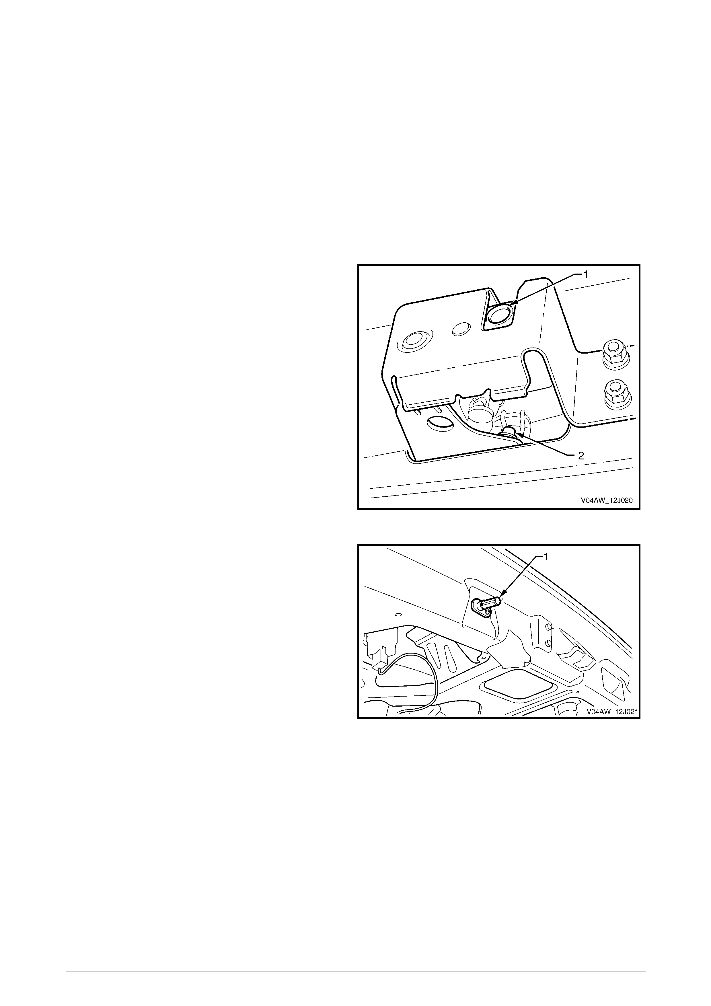
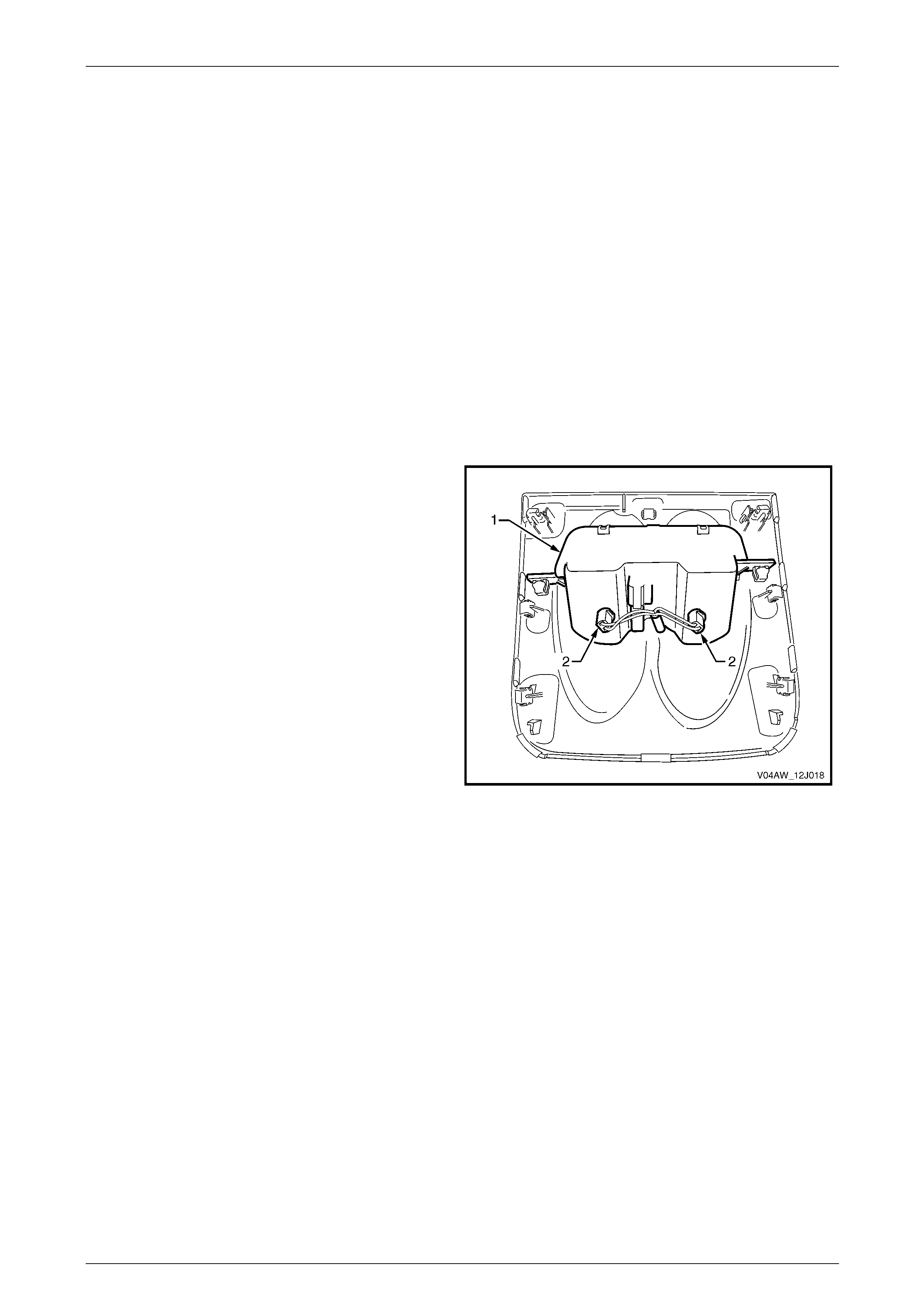
When the latch mechanism (1 ) releases the rear window
bracket, this action also releases the microswitch arm (2).
When this microswitch (S69) or the liftgate switch (S189) is
switched, the rear compartment lamp illuminates.
The operation of these switches also affects the function of
the rear wiper control module (A122).
Figure 12J – 6
Figure 12J – 7 shows the location of the liftgate switch (1).
This switch has dual pole contacts. One contact controls the
operation of the rear compartment lamp, while the other
signals the liftgate open or closed status to the rear wiper
control module.
Figure 12J – 7
Page 12J-7
Body Control Module 12J-8
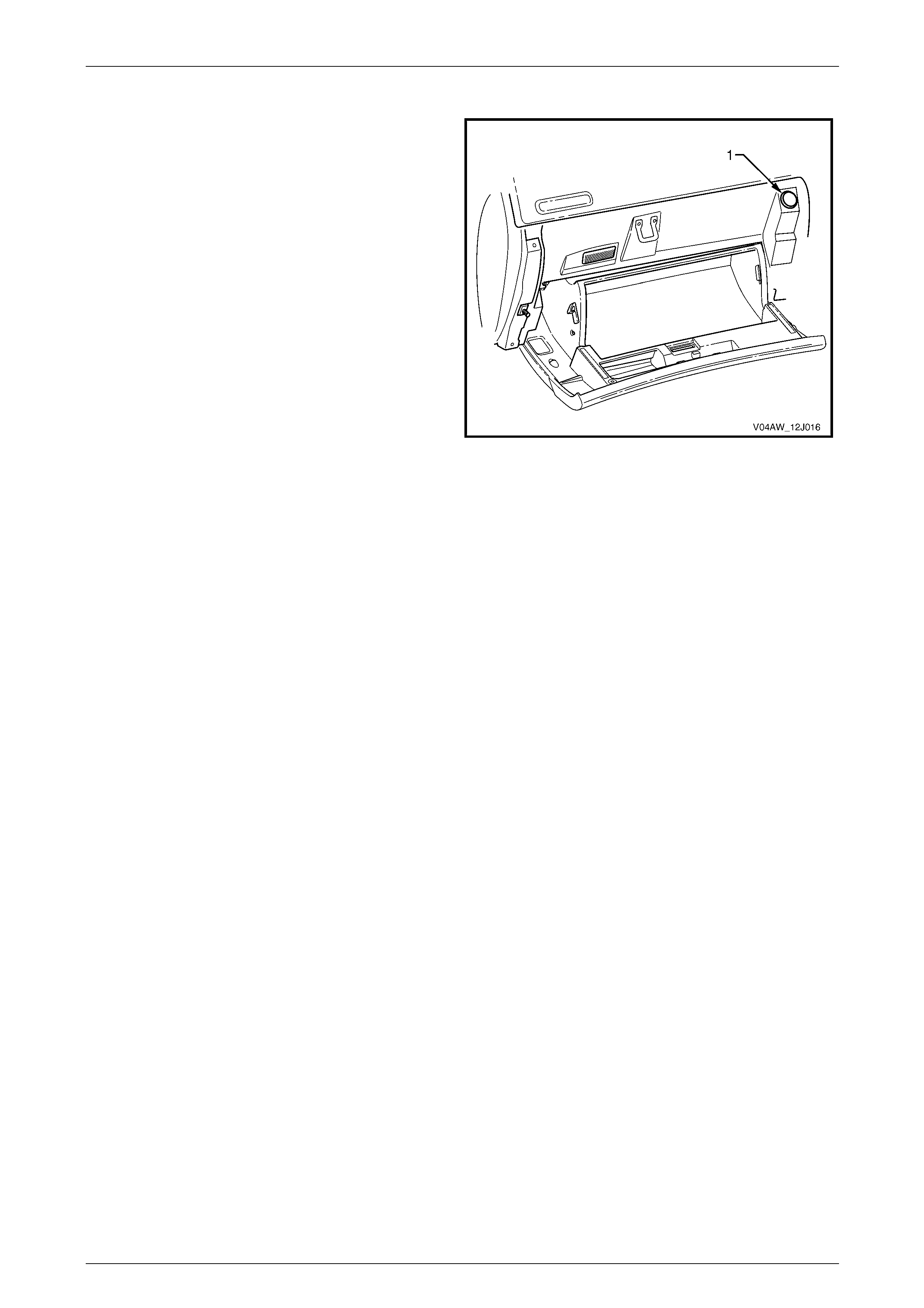
Rear Latch Releasing using the Instrument Pane l Compartment Button
The rear window release button (1) is located inside the
instrument panel compartment. When the button is pressed,
the latch releases in the same way as when the rear
window release button on the remote key is pressed.
Figure 12J – 8
Page 12J-8
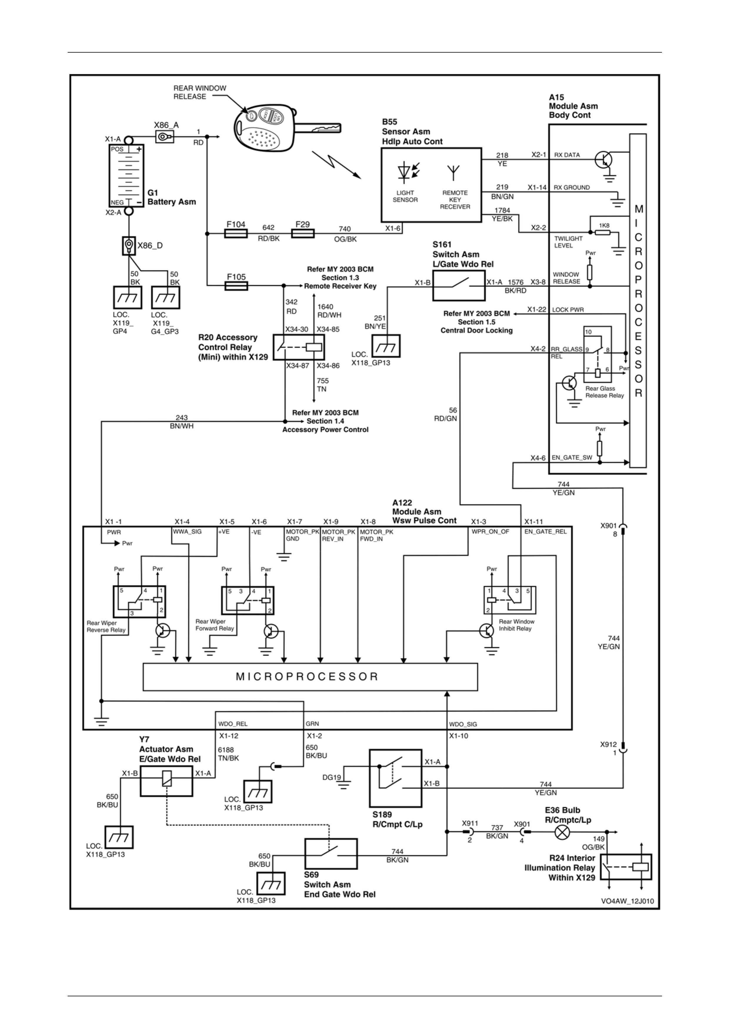
Body Control Module 12J-9
Figure 12J – 9
Page 12J-9
Body Control Module 12J-10
1.4 Instrumentation Illumination
MY 2004 AWD Wagon vehicles are fitted with Body Control Modules which features instrumentation illuminated control.
For a detailed description of the illumination system, refer to Section 12J, 1.14 Instrument Dimming Control in the
MY 2003 VY and V2 Service Information.
The following features, introduced for the MY 2004 AW D Wagon, are controlled via BCM terminal X1-5:
• Inclinometer gauges (P2).
• Occupant Climate Control (A14) buttons.
• Power/economy button on the automatic transmission centre console (E125).
• Cigar lighters (X133) located in the front and rear of the vehicle.
Figure 12J – 11 details the MY 2004 AWD W agon features that use BCM controlled dimming. Illumination dimming of the
Satellite Navigation System (A139) and the horn bar stereo controls is not controlled by the BCM.
Inclinometer (P2) Control Illumination
For a detailed description of how the inclinometer functions and how to adjust its indicators, refer to Section 12C,
1.1 General Description.
Fitted to the inclinometer assembly (1) are two lamps (2)
that illuminate the gaug es when the park lamps or
headlamps are switched on.
For lamp replacement information, refer to Section 12B,
2.4 Inclinometer Assembly.
Figure 12J – 10
Instrument Illumination System Checks
With the vehicle placed in a darkened area, check that:
• the gauge dials of the inclinometer assembly illuminate when the headlamp switch is in the Park or ON position,
and
• the illumination level of these gauge dials varies in accordance to the illumination level of the other d immer
controlled lighting.
For replacement information, refer to Section 12B, 2.4 Inclinometer Assembly.
Page 12J-10

Body Control Module 12J-11
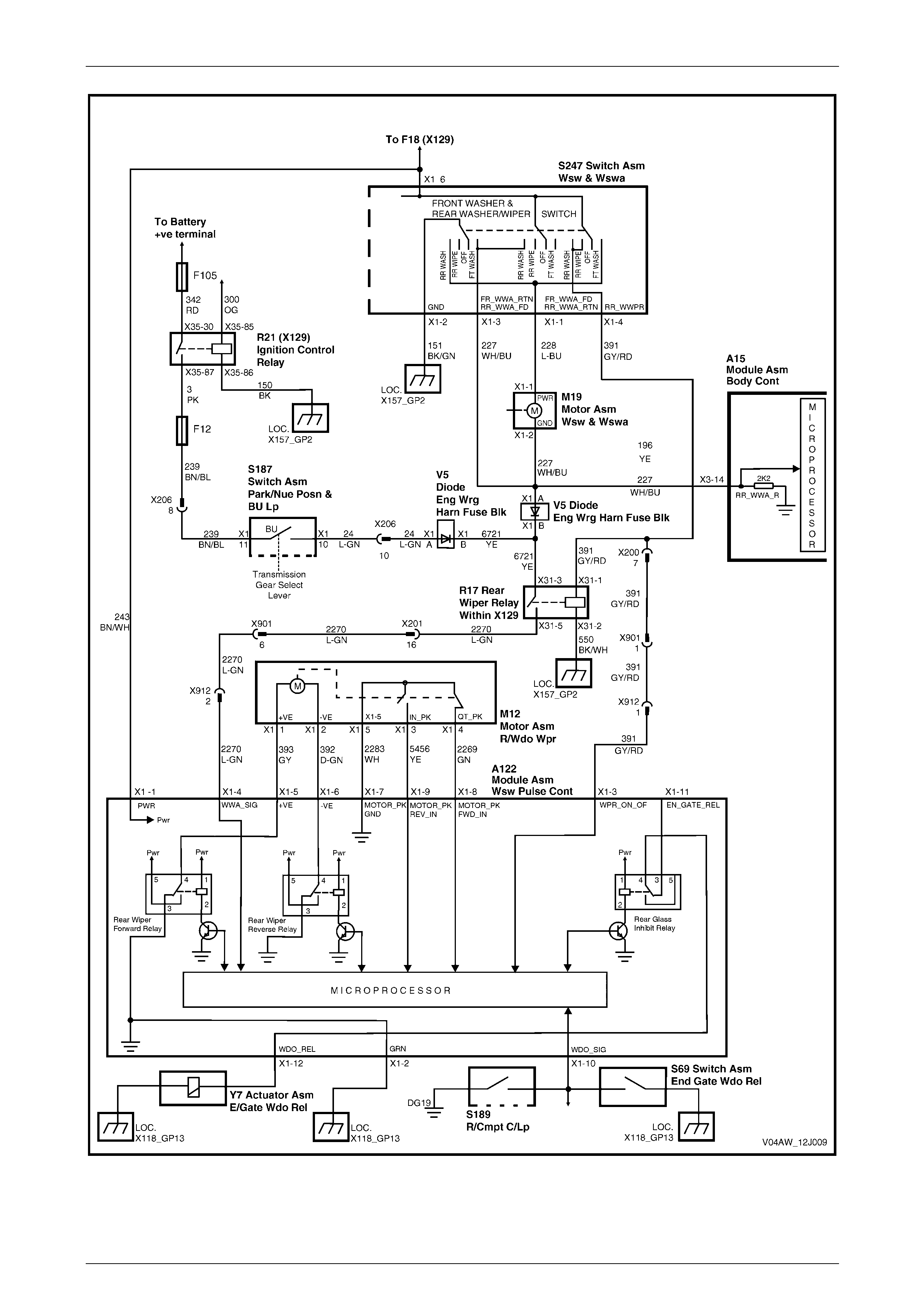
Figure 12J – 11
Page 12J-11

Body Control Module 12J-12
2 Service Operations
All BCM service operations carr y over from the MY 2003 VY and V2 Series vehicles, refer to Section 12J, 2 Service
Operations in the MY 2003 VY and V2 Series Service Information.
For service operations relating to the Rear W indow Control Module A122, refer to Section 12N, Wipers / Washers and
Horn.
For rear window latch actuator solenoid assembly (Y7) service operations, refer to Section 1A4, Hood, Rear
Compartment Lid, Liftgate & Endgate.
Page 12J-12

Body Control Module 12J-13
3 Tech 2 Diagnosis for BCM
The TECH 2 diagnostic proc edures are a carry over from the MY2003 VY and V2 Series vehicles except that the Model
Year selection on TECH 2 is now (4) 2004. The Vehicle Type selection is VY Series.
For further information on Tech 2 BCM Diagnostics, refer to Section 12J, 3 Tech 2 Diagnosis for BCM in the MY2003 VY
and V2 Series Service Information.
Page 12J-13

Body Control Module 12J-14
4 BCM Diagnostics
NOTE
Most BCM functions associated with the MY 2004
AWD Wagon carry over from the MY 2003
VY Series vehicles. For diagnostic information
not covered in this Section, refer to Section 12J,
4 Diagnostics in the MY 2003 VY and V2 Series
Service Information.
4.1 Rear Window Latch System Diagnostics
Introduction
A specific system wiring and electrical connector diagrams follow the diagnostic chart. As well, the vehicle wiring
diagrams can be used in conjunction with the diagnostic chart when diagnosing circuit faults. For electrical connector
locations and additional wiring diagram information, refer to Section 12P Wiring Diagrams.
When carrying out checks as directed to in the diagnostic chart, rather than probe terminals and connec tors with
incorrect sized multimeter connections, use the adaptors co ntained in connector test adaptor kit Tool No. KM-609. This
prevents spreading or damaging the wiring harness terminals.
At the completion of any diagnostic procedure, ensure that all diagnostic tools are removed and all rear window latch
release system components are correctly connected.
The rear window latch release s ystem is a unique feature on MY 2004 AWD Wagon. For details on the operation of the
latch actuator solenoid assem bl y (Y7), refer to the Rear Window Latch Control description in this Section.
Notes On Diagnostic Charts:
If any component or function abnormality is encountered during any test, rectify the problem and repeat the test before
continuing.
These diagnostic proced ures assume that the remaining vehicle systems are fully functional.
Test Description:
The numbers below refer to Step numbers in Diagnostic Chart A.
1–4 Checks that the rear compartment button on the remote coded key releases the rear window latch correctly.
6 Check vo ltage supply at the various locations within the system to ensure all is correct.
7 Checks the system ground connections.
8 Checks to determine if the BCM is supplying voltage to the rear wiper control module and the internal rea r window
inhibit relay.
9 Checks the internal circuit rear wiper inhibit relay contacts to ensure continuity when it is de-energised.
12 Checks to determine if the BCM is supplying battery voltage to terminal X3-8.
For procedures on checking wiring faults, refer to Section 12P, 3.1 Electrical Fault Diagnosis in the MY 2003 VY and V2
Series Service Information.
Page 12J-14

Body Control Module 12J-15
The electrical signal that drives the rear
window latch actuator solenoid requires
battery voltage to be applied to it for only
500 milliseconds (ms).
Under no circumstances should any external
voltage source be connected to the solenoid
coil to test it, otherwise serious damage to the
solenoid and the rear latch assembly may
occur.
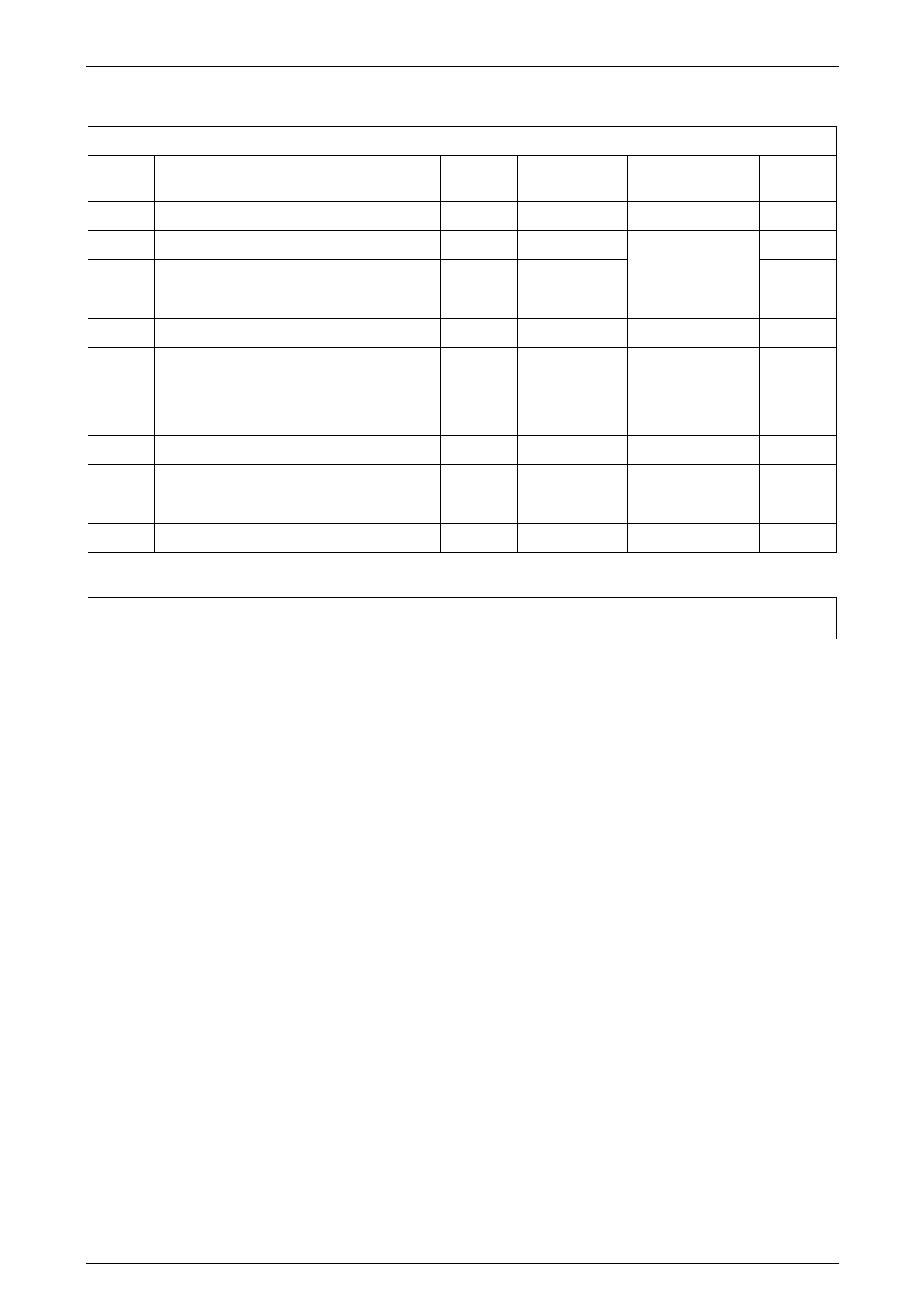
Rear Window Latch System Diagnostic Chart
Step Action Value(s) Yes No
1 1. Close the rear window and liftgate firmly.
2. Switch the rear wiper control switch (S247) on.
Is the rear wiper system operational?
Go to Step 2 Repair the rear
wiper system. Refer
to Section 12N,
Wipers/Washes and
Horn.
2 1. Switch the rear wiper control switch (S247) off.
2. Ensure the vehicle security system is disabled.
3. Using the remote coded key, press the rear
window release button.
Did the rear window latch release?
Close the rear
window.
Go to Step 3
Refer to
Section 12J,
4.3 Remote
Key/Receiver in the
MY 2003 VY and V2
Series Service
Information.
3 1. Unlock the vehicle.
2. Press the rear window release button (S161)
located in the instrument panel compartment.
Did the rear window latch release?
Close the rear
window.
Go to Step 4
Go to Step 5
4 1. Switch the rear wiper on.
2. Confirm that normal wiper action occurs.
3. Using the remote coded key, press the rear
compartment release button.
Did the rear window remain latched?
Turn the rear wiper
off.
System OK, end of
test.
Replace the rear
window control
module A122. Refer
Section 12N, Wipers
/ Washers and Horn.
5 1. Using a digital voltmeter, back-probe between the
rear window latch actuator soleno id (Y7)
connector terminals X1-A and X1-B.
2. Press the rear compartment release button.
Is the value as specified?
500 ms
battery
voltage
Replace rear
window latch
actuator assembly.
Refer to
Section 1A4, Hood,
Rear Compartment
Lid, Liftgate &
Endgate.
Go to Step 6
Page 12J-15

Body Control Module 12J-16
Step Action Value(s) Yes No
6 1. Using a digital voltmeter, back-probe between the
following connections and ground:
Rear wiper control module (A122), terminal X1-1,
circuit 243.
Accessory control relay (R 20), terminal X34-87
circuit 243.
Accessory control relay, terminal X34-30
circuit 342.
Fuse F105, circuit 342.
Accessory control relay, terminal X34-85
circuit 1640.
BCM (A15) terminal X1-22 circuit 440.
In all checks is the value as specified?
Battery
voltage Go to Step 7 Repair any faulty
power supply circuit.
Replace R20 and
F105 as necessary.
Check fuse F20 as
necessary.
7 1. Using a digital ohmmeter, back-probe between the
following connections and ground:
Rear wiper control module (A1 22), terminal X1-2
circuit 650.
Rear window release actuator solenoid (Y7),
terminal X1-B circuit 650.
Instrument panel compartment switch (S161),
terminal X1-B circuit 251.
In all checks is the value as specified?
0±0.2 ohm Go to Step 8 Repair any faulty
ground circuit.
8 1. Using a digital voltmeter, back-probe between the
rear wiper control module (A122) connector
terminal X1-11 and ground.
2. Press the rear window release button (an
assistant is required).
Is the value as specified?
500 ms
battery
voltage
Go to Step 9
Go to Step 10
9 1. Using a digital ohmmeter, back-probe between the
rear wiper control module (A122) connector
terminals X1-11 and X1-12.
Is the value as specified?
0±0.2 ohm Go to Step 10 Rear window inhibit
relay faulty. Replace
A122 module.
10 1. Using a digital ohmmeter, check circuit 6188 for
continuity between rear wiper control module
(A122) connector terminals X1-12 and rear
window latch solenoid connector terminal X1-A.
Is the value as specified?
0±0.2 ohm Replace rear
window latch
actuator assembly.
Refer to Section
1A4, Hood, Rear
Compartment Lid,
Liftgate & Endgate.
Repair open in
circuit 6188.
11 1. Using a digital voltmeter, back-probe between
BCM (A15) connector terminal X4-2 and ground.
2. Press the rear window release button (an
assistant is required).
Is the value as specified?
500 ms
battery
voltage
Repair open in
circuit 56 between
BCM and A122,
terminal X1-11.
Go to Step 12
12 1. Using a digital voltmeter, back-probe between
BCM (A15) connector terminal X3-8 and ground.
2. Press the rear window release button.
Is the value as specified?
Battery
voltage then
0 volt for the
duration the
switch is
pressed.
Replace BCM.
Refer to Section
12J 2.1 Body
Control Module in
the MY 2003 VY
and V2 Series
Service Information.
Go to Step 13
Page 12J-16

Body Control Module 12J-17
Step Action Value(s) Yes No
13 1. Using a digital voltmeter, back-probe between the
rear window release switch (S161) connector
terminal X1-A and ground.
Is the value as specified?
Battery
voltage Go to Step 14 Repair circuit 1576.
14 1. With the digital voltmeter connected as in Step 13,
press the rear window release button (S161) .
Is the value as specified?
Battery
voltage then
to 0 volt for
the duration
the switch is
pressed.
System OK. Replace the rear
compartment
release button.
Page 12J-17
Body Control Module 12J-18
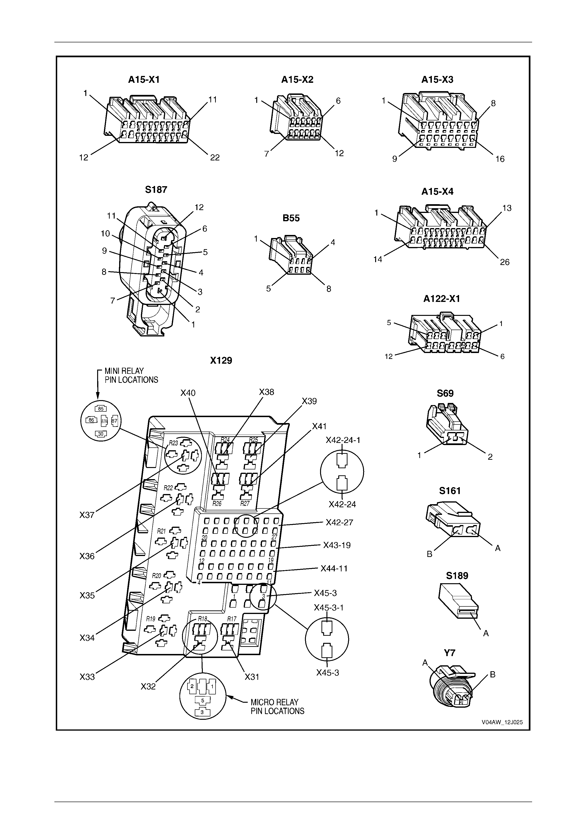
Figure 12J – 12
Page 12J-18
Body Control Module 12J-19
Figure 12J – 13
Page 12J-19
Body Control Module 12J-20
Figure 12J – 14
Page 12J-20

Body Control Module 12J-21
5 Specifications
Rear Wiper Control Module (A122)
Operating Voltage............................................................................................. DC 9.5 to 16 V
Rated Voltage.............................................................................................................DC 12 V
Standby Current..............................................................................................6 mA at 12V DC
Operating Temperature .........................................................................................–30 to 65oC
Storage Temperature.............................................................................................–40 to 85oC
Page 12J-21