
Wipers, Washers and Horn Page 12N–1
Page 12N–1
Section 12N
Wipers, Washers and Horn
ATTENTION
Before performing any service operation or other procedure described in this Section, refer to Section 00
Warnings, Cautions and Notes for correct workshop practices with regard to safety and/or property damage.
1 General Information............................................................................................................................... 3
1.1 Rear Wiper Assembly ............................................................................................................................................3
Rear Wiper ..............................................................................................................................................................3
Rear Wiper Control Module...................................................................................................................................4
Rear Wiper Motor Assembly..................................................................................................................................4
Rear Wiper Ramp ...................................................................................................................................................5
Rear Wiper Assembly Functional Operation........................................................................................................5
Intermittent Wipe Cycle Operation......................................................................................................................5
Continuous Wipe Mode ........................................................................................................... ...........................6
1.2 Rear Washer Assembly .........................................................................................................................................8
2 Service Operations – Wipers and Washers ........................................................................................ 9
2.1 Rear Wiper Blade Insert.........................................................................................................................................9
Replace ...................................................................................................................................................................9
2.2 Rear Wiper Blade Assembly................................................................................................................................10
Remove .................................................................................................................................................................10
Reinstall ................................................................................................................................................................10
2.3 Rear Wiper Arm Assembly ..................................................................................................................................11
Remove .................................................................................................................................................................11
Reinstall ................................................................................................................................................................11
2.4 Rear Wiper Ramp .................................................................................................................................................13
Remove .................................................................................................................................................................13
Reinstall ................................................................................................................................................................13
2.5 Rear Wiper Control Module.................................................................................................................................14
Remove .................................................................................................................................................................14
Reinstall ................................................................................................................................................................14
2.6 Rear Wiper Motor Assembly................................................................................................................................15
Prerequisites.........................................................................................................................................................15
Safety Requirements........................................................................................................................................15
Equipment ........................................................................................................................................................15
Testing Procedures...........................................................................................................................................15
Diagnose Rear Wiper Motor Assembly Wiring ..................................................................................................16
Introduction.......................................................................................................................................................16
Test Description................................................................................................................................................16
Notes on the Diagnostic Chart..........................................................................................................................17
Diagnose Rear Wiper Motor Assembly Operation.............................................................................................19
Introduction.......................................................................................................................................................19
Test Description................................................................................................................................................19
Wiper Motor Limit Switches Malfunction Table.................................................................................................20
Diagnose Rear Wiper Assembly and Liftgate Interface Operation ..................................................................21
Introduction.......................................................................................................................................................21
Test Description................................................................................................................................................21
Notes on the Diagnostic Chart..........................................................................................................................22
Remove .................................................................................................................................................................24
Reinstall ................................................................................................................................................................25
2.7 Wiring Diagram – Wipers and Washers..............................................................................................................26

Wipers, Washers and Horn Page 12N–2
Page 12N–2
2.8 Wiring Diagram – Rear Wiper Control Module...................................................................................................27
2.9 Connector Diagrams – Wipers and Washers – Chart A....................................................................................28
2.10 Connector Diagrams – Wipers and Washers – Chart B....................................................................................29
3 Torque Wrench Specifications........................................................................................................... 30

Wipers, Washers and Horn Page 12N–3
Page 12N–3
1 General Information
With the following exceptions, MY 2004 VY AWD Wagon wipers, washers and horn information carries over from
MY 2003 VY Wagon vehicles. For information not contained within this Section, refer to Sectio n 12N Wipers, Washers
and Horn in the MY 2003 VY and V2 Series Service Information.
• Rear wiper blade insert,
• Rear wiper arm assembly,
• Rear wiper ramp,
• Rear wiper control module,
• Rear wiper motor assembly,
• Rear washer assembly,
• Wiring diagram, and
• Connector diagrams.
NOTE
Refer to the relevant MY 2004 VY AWD Wagon
Section for all external references contained in
the MY 2003 VY and V2 Series, Section 12N
Wipers, Washers and Horn. This is to verify that
there are no differences in the MY 2004 VY AWD
Wagon Service Information that will affect the
service procedures referenced from the MY 2003
VY and V2 Series Service Information.
1.1 Rear Wiper Assembly
The rear wiper assembly is not controlled by the body control module (BCM) as in MY 2003 VY Wagon vehicles. The
control functions have been transferred to a rear wiper control module (A122).
Rear Wiper
When the rear wiper has been operating,
before turning off the ignition switch ensure
that the rear wiper arm is in the offscreen park
position. If failing to do so, the situation could
arise where the liftgate window could be
opened with the rear wiper stoped on the
glass panel and vehicle damage could occur.
When the rear wiper is not in operation it parks below the liftgate window, the arm resting on the rear wiper ramp,
protective clear PVC tape is applied to the liftgate where the wiper blade is resting. This parking position enables the
hinged liftgate window to be opened outward with the rear wiper staying clear of the glass panel.
With the ignition switch in the ON or ACC position, if the liftgate is in the open state when the rear wiper switch is moved
to the ON position, the rear wiper will not operate. For the rear wiper to be operational again, close the liftgate, then
move the rear wiper switch to the OFF position and back to the ON position again. The same condition applies if the
liftgate window is in the open state when the rear wiper switch is moved to the ON position.
If the rear wiper is operating, the liftgate window cannot be opened.
If the liftgate window is closed and the liftgate only is opened while the rear wiper is operating, the wipe mode will not
stop. Move the rear wiper switch to the OFF position to stop the operation of the rear wiper; the operation cannot be
restarted before the liftgate is closed.
Wipers, Washers and Horn Page 12N–4
Page 12N–4
With the ignition switch in the ON or ACC position the functions of the rear wiper are as follow:
• When the rear wiper switch is ON, the rear wiper activates intermittently at 9 second intervals.
• When the rear wiper switch is ON and the reverse gear is selected, the intermittent operation of the rear wiper goes
into continuous wipe mode until the reverse gear is deselected.
• When the rear washer is selected, the rear wiper action is continuous wipe mode until the rear washer switch is
released.
• When the rear wiper is operating and the rear washer is selected, the intermittent operation of the rear wiper goes
into continuous wipe mode until the rear washer switch is released.
• When the rear wiper or washer switch is moved from the ON to OFF position, the rear wiper suspends for one
second in the furthest on-screen park position then returns to the off-screen park position.
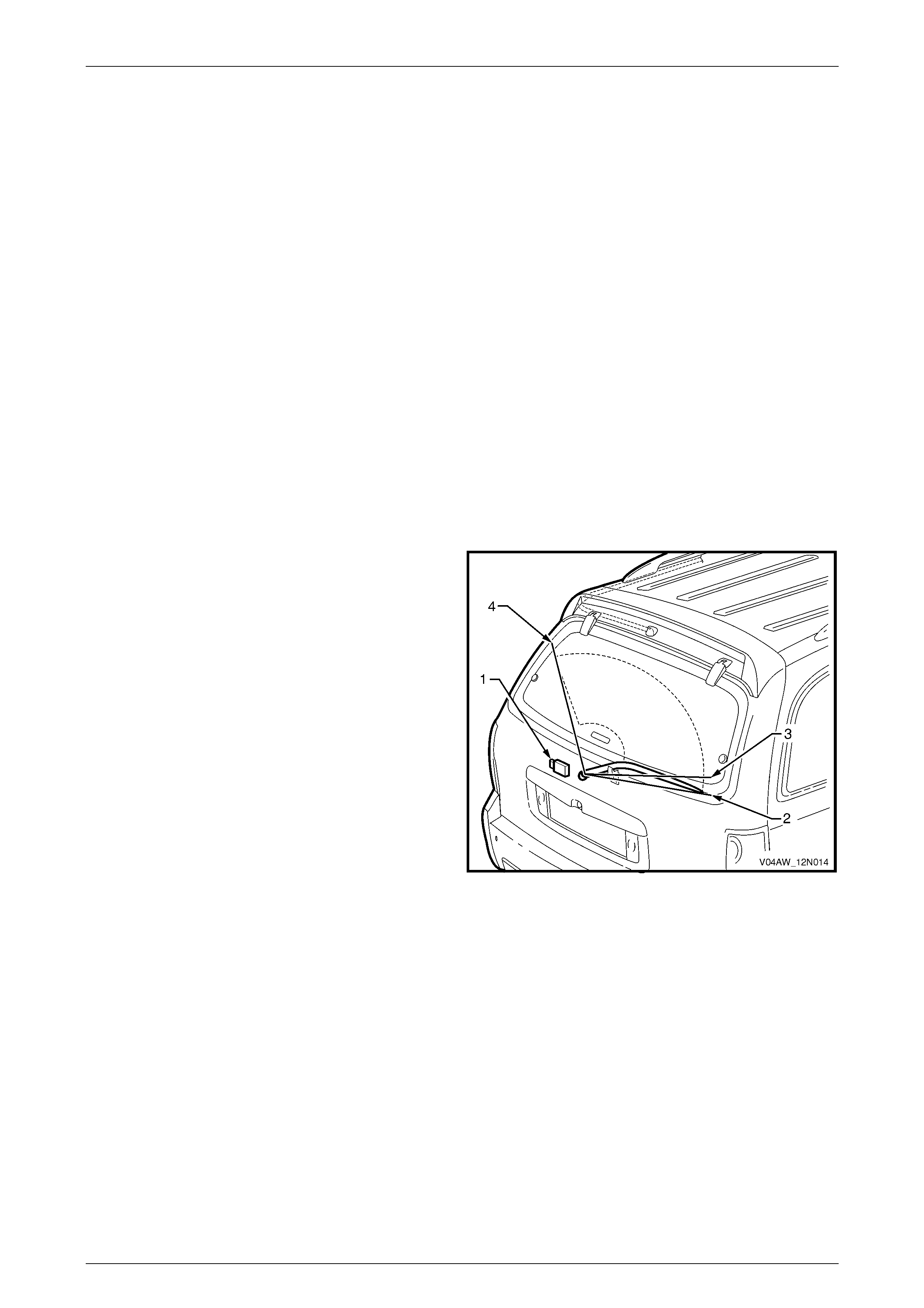
Rear Wiper Control Module
The rear wiper control module (1) is installed in the liftgate. It controls the various functions of the rear wiper / washer.
The rear wiper control module also provides a link with the liftgate window release actuator (2), the liftgate window
microswitch (3) (within the latch) and the liftgate switch (4) refer to Figure 12N – 2.
For a description and functions of the liftgate window release actuator, liftgate window microswitch and liftgate switch
refer to Section 1A4 Hood, Rear Compartment Lid, Liftgate and Endgate.
The rear wiper module will inhibit the rear wiper operation if the liftgate and/or the liftgate window are open.
The rear wiper module triggers the liftgate window release. The liftgate window release actuator solenoid is inhibited if
the rear wiper switch or the rear washer switch is ON.
Before permitting the wiper motor to operate, the rear wiper
control module (1) monitors the positions of both the liftgate
and the liftgate window latch.
The rear wiper control module also monitors the rear wiper
three park positions:
• rear wiper offscreen park position (2),
• rear wiper onscreen park position (3), and
• rear wiper furthest onscreen park position (4).
Figure 12N – 1
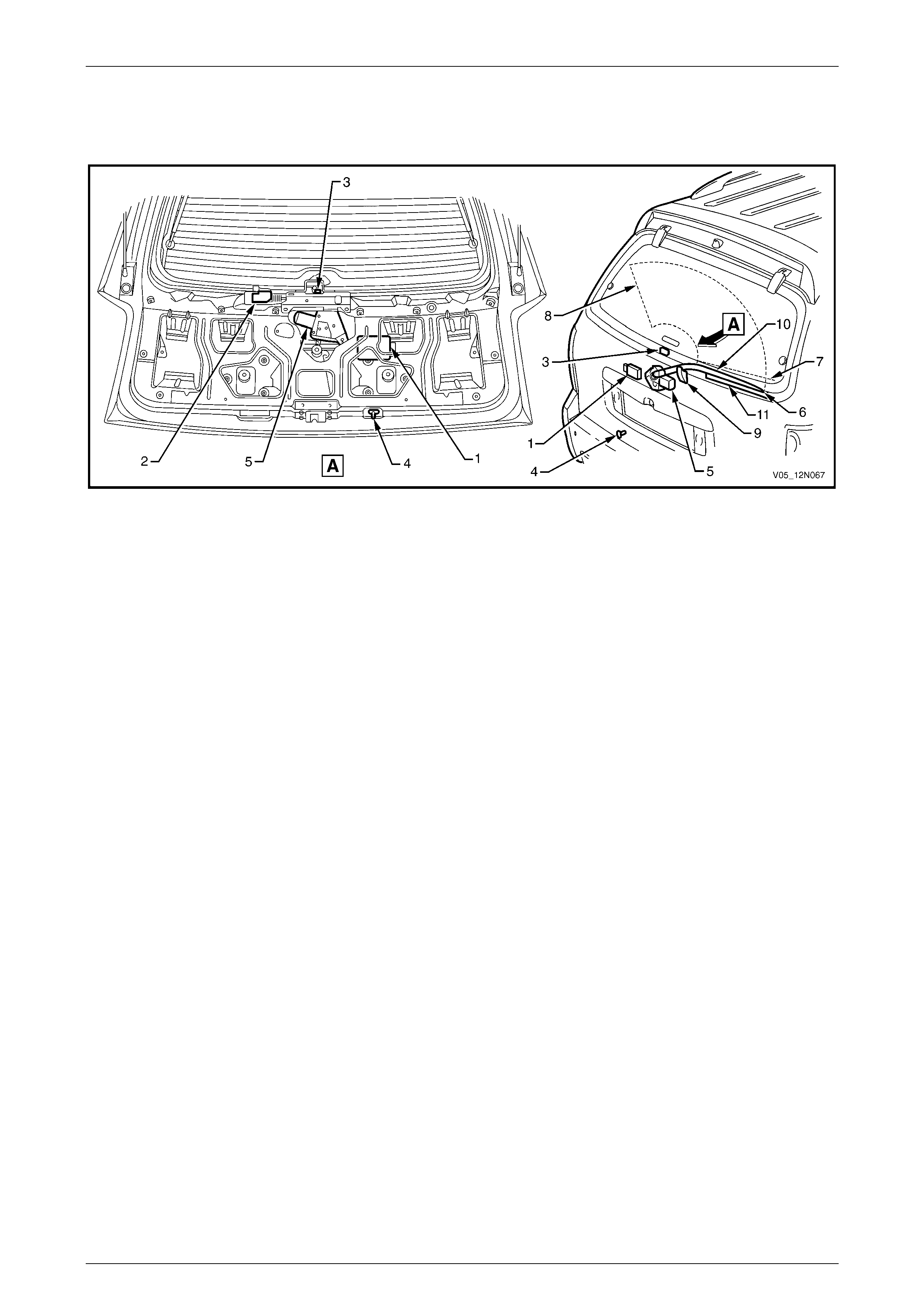
Rear Wiper Motor Assembly
The rear wiper motor assembly (5) is introduced to suit the opening liftgate window and offscreen parking (6) of the rear
wiper arm, refer to Figure 12N – 2.
The rear wiper motor assembly has a forward park and a reverse park limit switches mechanically linked to the wiper arm
driveshaft. The forward park limit switch determines when the wiper arm is at the start of the wipe sweep (7) (onscreen
park position), while the reverse park limit switch determines when the wiper arm has reached the full wipe sweep (8)
(furthest onscreen park position).
The rear wiper motor assembly operates either in the forward direction to drive the rear wiper arm for the wiping of the
liftgate window, or in the reverse direction to drive the rear wiper arm to the offscreen park position.
Wipers, Washers and Horn Page 12N–5
Page 12N–5
Rear Wiper Ramp
The rear wiper ramp (9) is attached to the liftgate below the liftgate window for the offscreen parking of the rear wiper
arm (10), refer to Figure 12N – 2.
Figure 12N – 2
Legend
1 Rear Wiper Control Module A122
2 Liftgate Window Release Actuator Y7
3 Liftgate Window Microswitch S69
4 Liftgate Switch S189
5 Rear Wiper Motor Assembly M12
6 Rear Wiper Arm Offscreen Park
Position
7 Wipe Sweep Start (Rear Wiper Arm
Onscreen Park Position)
8 Full Wipe Sweep (Rear Wiper Arm
Furthest Onscreen Park Position)
9 Rear Wiper Ramp
10 Rear Wiper Arm
11 Protective Tape (where fitted)
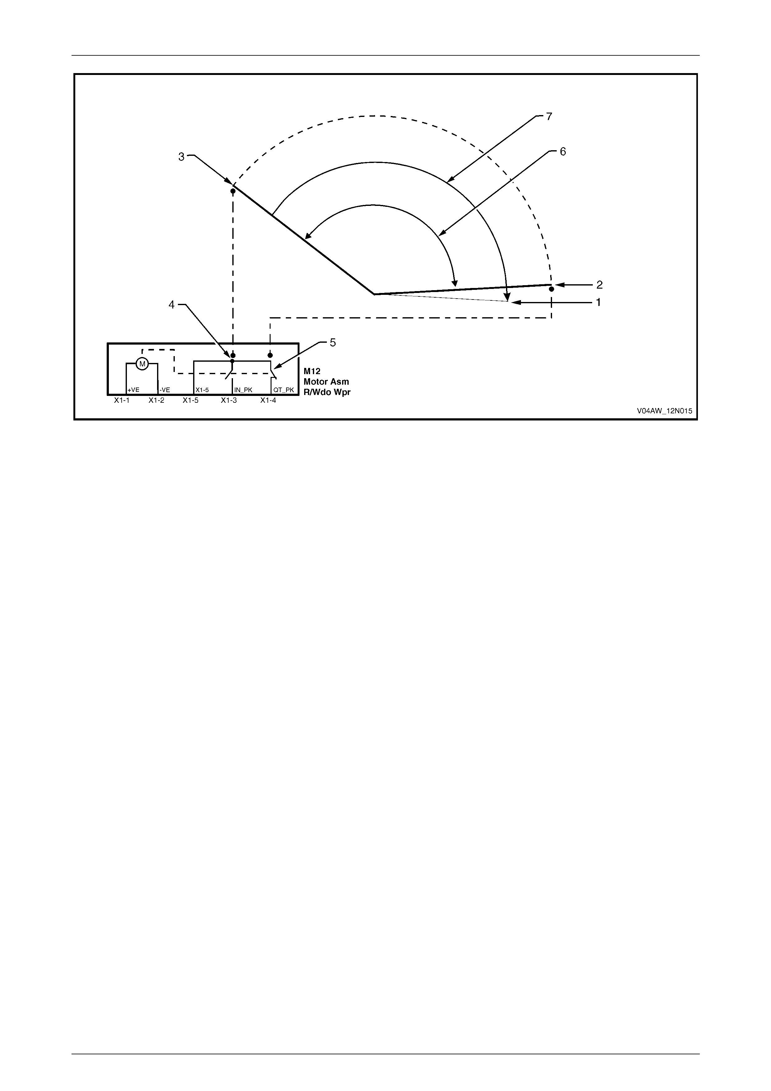
Rear Wiper Assembly Functional Operation
For the rear wiper assembly functional operation description, refer to Figure 12N – 3.
Intermittent Wipe Cycle Operation
A wipe cycle consists of the rear wiper arm movement from the onscreen park position (2) to the furthest onscreen park
position (3) and back to the onscreen park position (2).
With the ignition switch ON, when the rear wiper/washer switch is moved to the ON position, the rear wiper motor
operates in the forward direction (6) for one wipe cycle and then waits for 9 seconds before resuming the next wipe
cycle. This procedure is repeated until the rear wiper/washer switch is moved to the OFF position.
During this cycle, the rear wiper control module supplies power to the rear wiper motor. The forward park limit switch (5)
in the rear wiper motor opens when the rear wiper arm leaves the onscreen park position (2) and moves in the forward
direction (6) towards the furthest onscreen park position (3). The reverse park limit switch (4) in the motor closes when
the rear wiper arm reaches the furthest onscreen park position (3), then it opens when the rear wiper arm leaves this
position (3) and returns towards the onscreen park position (2). The forward park limit switch (5) in the rear wiper motor
closes when the rear wiper arm reaches the onscreen park position (2). At this point, the rear wiper control module
disconnects the power to the rear wiper motor and the rear wiper arm remains stationary at the onscreen park
position (2) for 9 seconds until the next wipe cycle occurs.
When the rear wiper/washer switch is moved to the OFF position the following occurs.
• If the rear wiper arm is in the onscreen park position (2), the rear wiper control module supplies power to the rear
wiper motor. The rear wiper arm moves in the forward direction (6) towards the furthest onscreen park position (3)
where it stops. The reverse park limit switch (4) in the motor closes when the rear wiper arm reaches the furthest
onscreen park position (3) and the rear wiper arm remains stationary for 1 second. Then the rear wiper control
module reverses polarity to the rear wiper motor which turns in the reverse direction (7). The reverse park limit
switch (4) opens when the rear wiper arm leaves the furthest onscreen park position (3) and moves all the way to
the offscreen park position (1).

Wipers, Washers and Horn Page 12N–6
Page 12N–6
• If the rear wiper arm is moving towards the furthest onscreen park position (3), it continues to move to this position
where it stops. The reverse park limit switch (4) in the motor closes when the rear wiper arm reaches the furthest
onscreen park position (3) and the rear wiper arm remains stationary for 1 second. Then the rear wiper control
module reverses polarity to the rear wiper motor which turns in the reverse direction (7). The reverse park limit
switch (4) opens when the rear wiper arm leaves the furthest onscreen park position (3) and moves all the way to
the offscreen park position (1).
• If the rear wiper arm is moving towards the onscreen park position (2), the rear wiper control module supplies
power to the rear wiper motor until the rear wiper arm reaches the furthest onscreen park position (3) where it
stops. The reverse park limit switch (4) in the motor closes when the rear wiper arm reaches the furthest onscreen
park position (3) and the rear wiper arm remains stationary for 1 second. Then the rear wiper control module
reverses polarity to the rear wiper motor which turns in the reverse direction (7). The reverse park limit switch (4)
opens when the rear wiper arm leaves the furthest onscreen park position (3) and moves all the way to the
offscreen park position (1).
Continuous Wipe Mode
With the ignition switch ON, the rear wiper operates in continuous wipe mode when:
• the rear wiper/washer switch is pushed and held forward, or
• the rear wiper/washer switch is in the ON position and the reverse gear is selected.
During this wipe mode, the rear wiper motor operates in the forward direction (6). The rear wiper arm moves continuously
between the furthest onscreen park position (3) and the onscreen park position (2). The reverse park limit switch (4) and
the forward park limit switch (5) in the rear wiper motor close and re-open alternatively as the rear wiper arm reaches the
two park positions (2 and 3). The rear wiper control module supplies constant power to the rear wiper motor.
When the rear wiper/washer switch is released from the forward position the following occurs.
• If the rear wiper/washer switch is in the OFF position, the rear wiper motor continues to operate in the forward
direction (6) until the rear wiper arm reaches the furthest onscreen park position (3) where it stops. The reverse
park limit switch (4) in the motor closes when the rear wiper arm reaches the furthest onscreen park position (3)
and the rear wiper arm remains stationary for 1 second. Then the rear wiper control module reverses polarity to the
rear wiper motor which turns in the reverse direction (7). The reverse park limit switch (4) opens when the rear
wiper arm leaves the furthest onscreen park position (3) and moves all the way to the offscreen park position (1).
• If the rear wiper/washer switch is in the ON position, the rear wiper motor continues to operate in the forward
direction (6) until the rear wiper arm reaches the onscreen park position (2). The forward park limit switch (5) in the
motor closes when the rear wiper arm reaches the onscreen park position (2). At this point the rear wiper control
module disconnects the power to the rear wiper motor and the rear wiper arm remains stationary at the onscreen
park position (2) for 9 seconds until the next intermittent wipe cycle occurs.
When the reverse gear is deselected, the rear wiper motor continues to operate in the forward direction (6) until the rear
wiper arm reaches the onscreen park position (2). The forward park limit switch (5) in the motor closes when the rear
wiper arm reaches the onscreen park position (2). At this point the rear wiper control module disconnects the power to
the rear wiper motor and the rear wiper arm remains stationary at the onscreen park position (2) for 9 seconds until the
next intermittent wipe cycle occurs.
Wipers, Washers and Horn Page 12N–7
Page 12N–7
Figure 12N – 3
Legend
1 Rear Wiper Arm Offscreen Park
Position
2 Rear Wiper Arm Onscreen Park
Position
3 Rear Wiper Arm Furthest Onscreen
Park Po sitio n
4 Rear Wiper Motor Reverse Park Limit
Switch
5 Rear Wiper Motor Forward Park Limit
Switch
6 Rear Wiper Motor Forward Direction
7 Rear Wiper Motor Reverse Direction

Wipers, Washers and Horn Page 12N–8
Page 12N–8
1.2 Rear Washer Assembly
With the exception of the rear wiper control module, MY 2004 VY AWD Wagon washers information carries over from
MY 2003 VY Wagon vehicles. For information not contained within this Section, refer to Sectio n 12N Wipers, Washers
and Horn in the MY 2003 VY and V2 Series Service Information.
The rear washer assembly is not controlled by the body control module (BCM) as in MY 2003 VY Wagon vehicles. The
control functions have been transferred to the rear wiper control module.
Wipers, Washers and Horn Page 12N–9
Page 12N–9
2 Service Operations – Wipers and
Washers
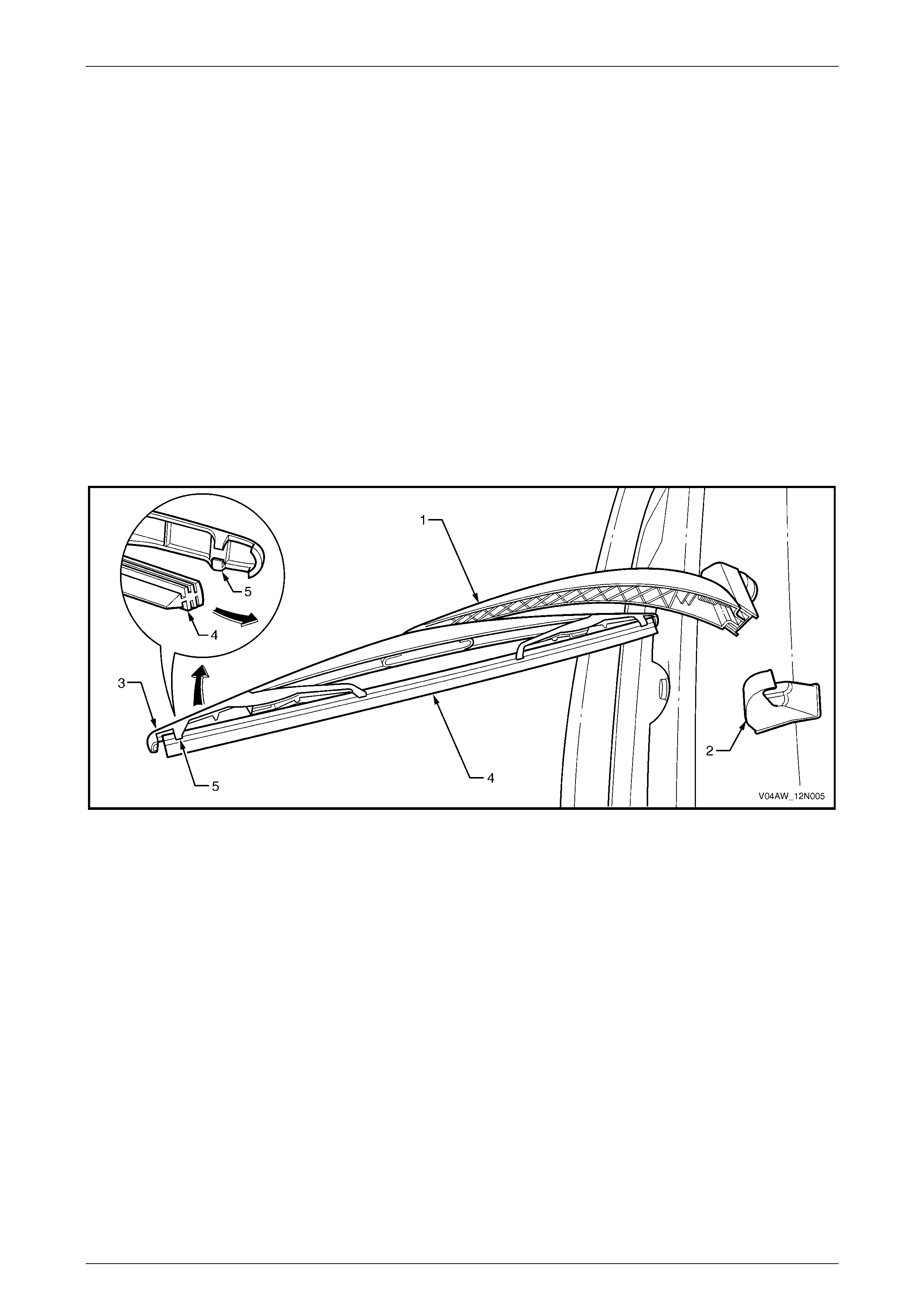
2.1 Rear Wiper Blade Insert
LT Section –
Replace
1 Lift the rear wiper arm (1) away from the rear wiper ramp (2), refer to Figure 12N – 4.
2 Move the end of the rear wiper blade (3) outward and disengage the insert (4) from the rear wiper blade claw (5).
3 Slide the insert out of the rear wiper blade and discard.
4 Slide the new insert into the rear wiper blade ensuring that the insert passes through each rear wiper blade claw.
5 If required, replace the clear protective tape on the liftgate located at the resting position of the rear wiper blade.
6 Position the rear wiper arm on the rear wiper ramp.
Figure 12N – 4
Wipers, Washers and Horn Page 12N–10
Page 12N–10
2.2 Rear Wiper Blade Assembly
LT Section –
Remove
1 Lift the rear wiper arm assembly (1) from the liftgate.
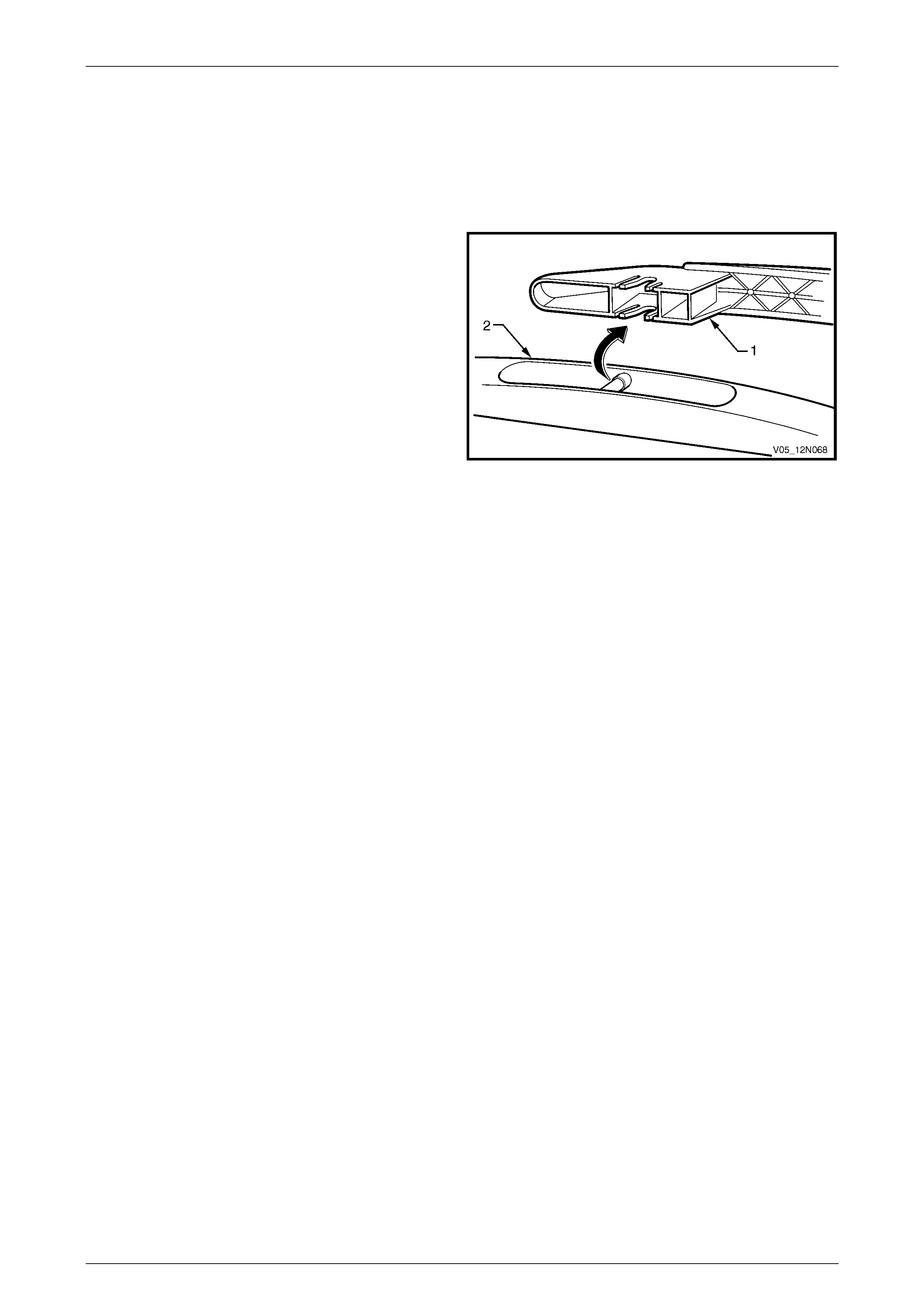
2 Pull the blade assembly (2) out of the arm assembly
and remove.
Figure 12N – 5
Reinstall
1 Push the rear wiper blade assembly (2) into the front wiper arm assembly (1) and ensure that it is secured, refer to
Figure 12N – 5.
2 Lower the rear wiper arm assembly onto the liftgate.
Wipers, Washers and Horn Page 12N–11
Page 12N–11
2.3 Rear Wiper Arm Assembly
LT Section –
Remove
1 Ensure that the rear wiper motor assembly is in the
offscreen park position.
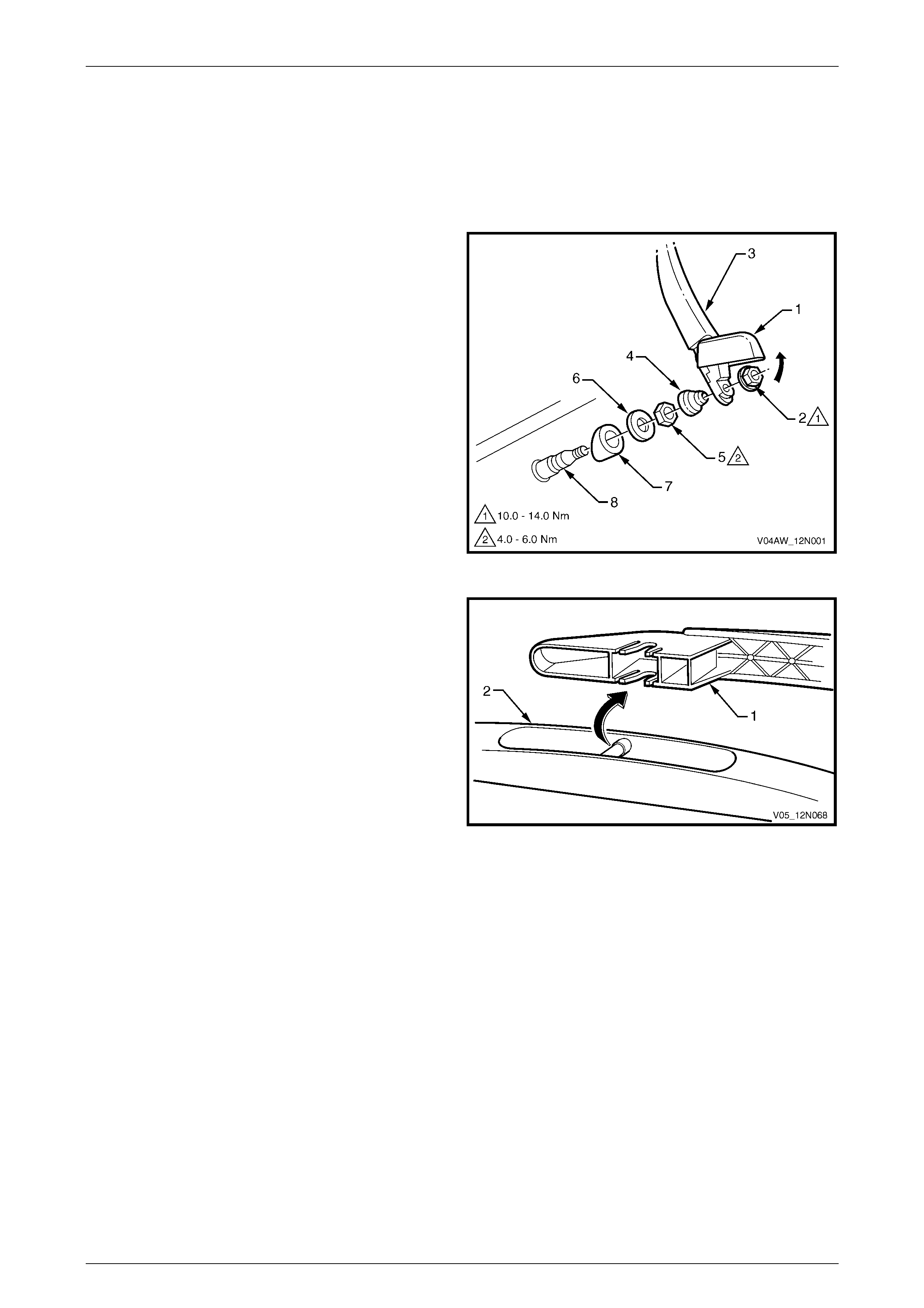
2 Lift the cap (1) and remove the nut (2) attaching the
rear wiper arm assembly (3) to the rear wiper motor
pivot (8).
3 Remove the rear wiper arm assembly from the rear
wiper motor pivot.
4 If needed remove the cover (4), nut (5), cap (6) and
outer spacer (7) from the rear wiper motor pivot.
Figure 12N – 6
5 If required, pull the rear wiper blade assembly (1) from
the arm assembly (2) and remove.
Figure 12N – 7
Reinstall
Installation of the rear wiper arm assembly is the reverse of the removal procedure, noting the following:
1 If removed, push the rear wiper blade assembly (1) into the front wiper arm assembly (2) and ensure that it is
secured, refer to Figure 12N – 7
2 Ensure that the rear wiper motor assembly is in the offscreen park position.
Wipers, Washers and Horn Page 12N–12
Page 12N–12
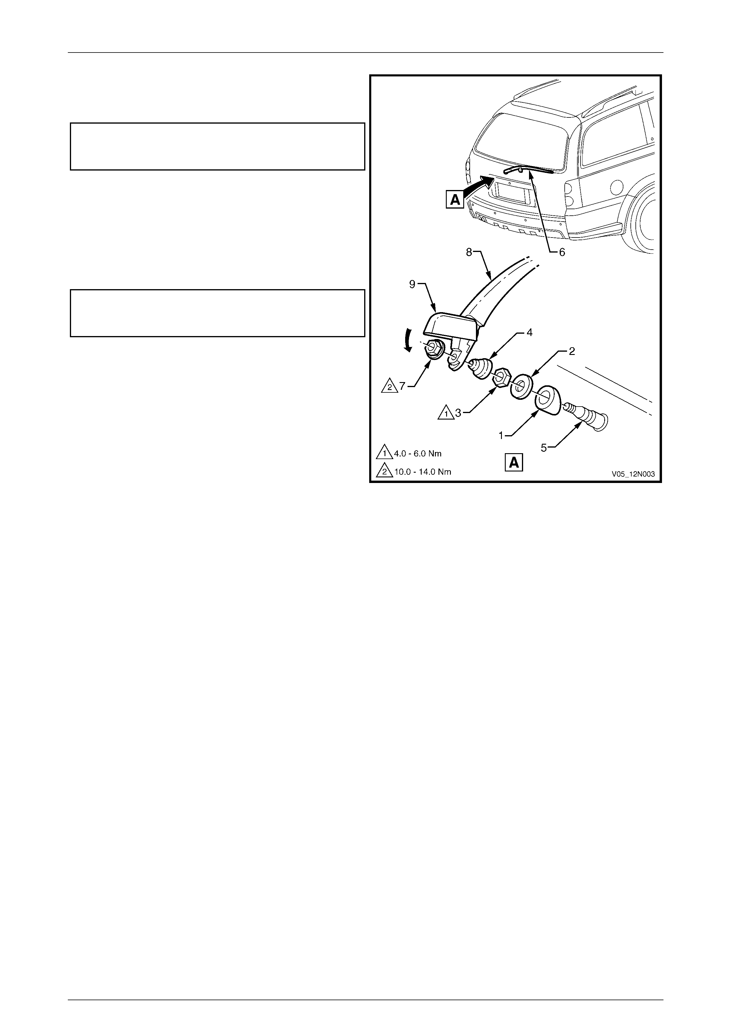
3 If removed, install the rear wiper motor outer
spacer (1), cap (2) and attaching nut (3). Tighten the
nut to the correct torque specification.
Rear window wiper motor assembly
attaching nut
torque specific atio n ....................................4.0 – 6.0 Nm
4 Install the cover (4) onto the rear wiper motor pivot (5).
Install the rear wiper arm assembly onto the rear wiper
motor pivot so that the rear wiper arm rests on the rear
wiper ramp (6).
5 Install the nut (7) attaching the rear wiper arm
assembly (8) to the rear wiper motor pivot and tighten
to the correct torque specifi cat i on.
Rear window wiper arm assembly
attaching nut
torque specification ................................10.0 – 14.0 Nm
6 Push the trim cap (9) onto the rear wiper arm
assembly.
7 Check the rear wiper for correct operation.
NOTE
Ensure that the rear wiper arm assembly parks
in the offscreen position on the rear wiper ramp.
Figure 12N – 8
Wipers, Washers and Horn Page 12N–13
Page 12N–13
2.4 Rear Wiper Ramp
LT Section –
Remove
1 Remove the liftgate lower trim panel, refer to
Section 1A4 Hood, Rear Compartment Lid, Liftgate
and Endgate.
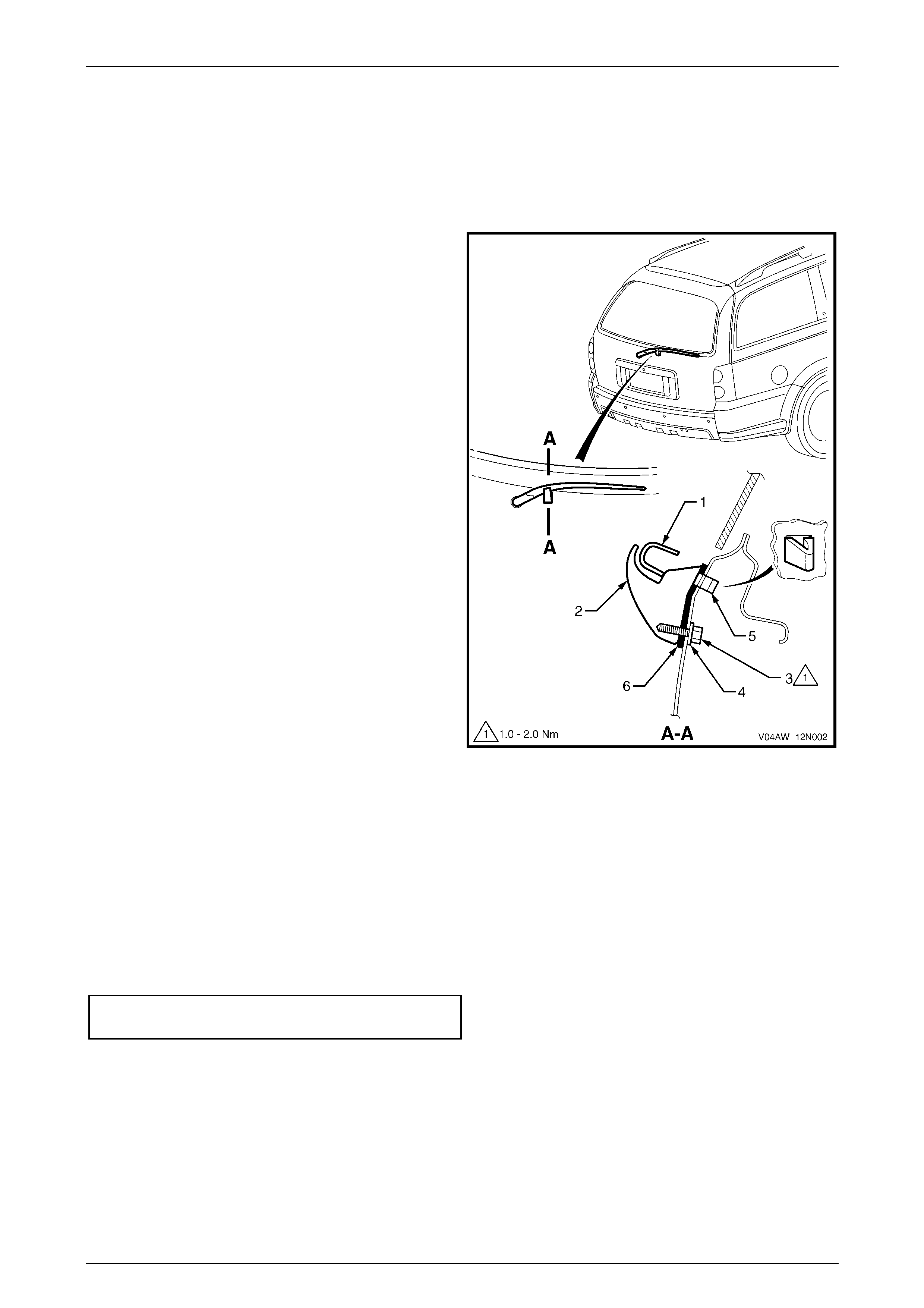
2 Lift the rear wiper arm (1) away from the rear wiper
ramp (2).
3 Remove the attaching screw (3) and washer (4) from
the inner side of the liftgate panel.
4 Depress the tang (5), then remove the rear wiper ramp
and seal (6) from the liftgate.
Figure 12N – 9
Reinstall
Installation of the rear wiper ramp is the reverse of the removal procedure, noting the following:
1 Ensure that the seal (6) is not damaged and replace if necessary. Refer to Figure 12N – 9.
2 Position the rear wiper ramp (2) and seal on the liftgate with the tang (5) inserted in the locating hole.
3 Ensure that the rear wiper ramp is securely attached to the liftgate. Tighten the attaching screw (3) to the specified
torque.
4 Ensure that the rear wiper arm is parking properly on the rear wiper ramp.
Rear window wiper ramp attaching
screw torque specification.......................... 1.0 – 2.0 Nm
Wipers, Washers and Horn Page 12N–14
Page 12N–14
2.5 Rear Wiper Control Module
LT Section –
Remove
1 Remove the rear wiper fuse F18 from the passenger
compartment fuse and relay panel assembly. Refer to
Section 12O Fuses, Relays and Wiring Harnesses.
2 Remove the liftgate lower trim panel, refer to
Section 1A4 Hood, Rear Compartment Lid, Liftgate
and Endgate.
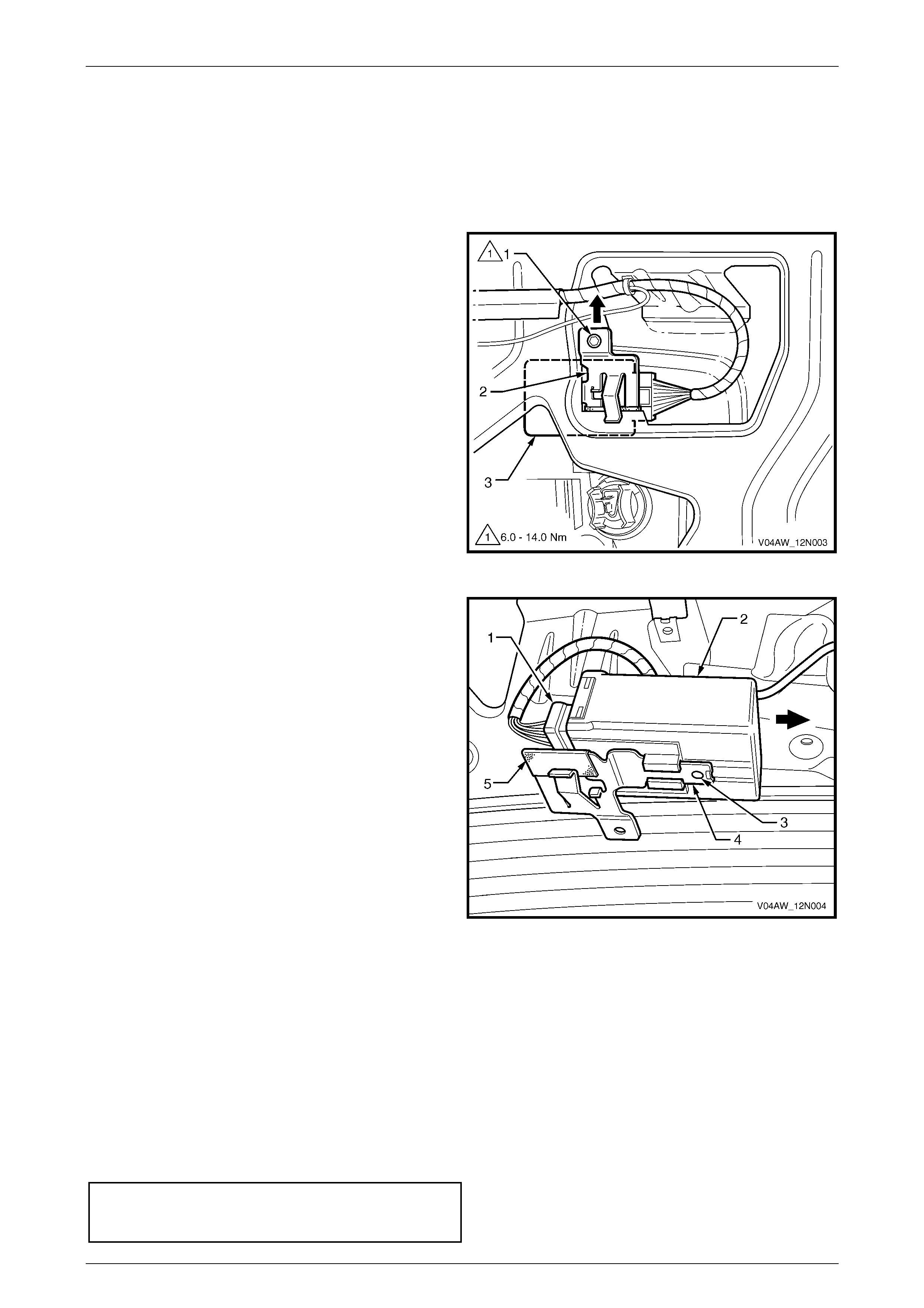
3 Remove the attaching screw (1) securing the support
bracket (2) and control module (3) to the liftgate.
4 Pull to disengage the support bracket and control
module from the liftgate.
Figure 12N – 10
5 Remove the connector (1) from the control module (2).
6 Disengage the tab (3) and slide the control module to
separate it from the support bracket (4).
NOTE
Check that the protective tape (5) fitted to the
support bracket has not been damaged during
the removal procedure.
Figure 12N – 11
Reinstall
Installation of the rear wiper control module is the reverse of the removal procedure, noting the following:
1 Check that the protective tape (5) is fitted to the support bracket and is not damaged, replace if necessary. Refer to
Figure 12N – 11
2 Ensure that the rear wiper control module (2) is securely fitted to the support bracket (4) with the tab (3) engaged.
3 Connect the wiring harness connector (1).
4 Ensure that the support bracket is correctly fitted and securely attached to the liftgate. Tighten the attaching
screw (1) to the specified torque, refer to Figure 12N – 10.
Rear window wiper
control modu le sup port brac ke t
attaching screw torque specification......... 6.0 – 14.0 Nm

Wipers, Washers and Horn Page 12N–15
Page 12N–15
2.6 Rear Wiper Motor Assembly
LT Section –
Prerequisites
Safety Requirements
When operating the rear wiper motor assembly as part of any of the Steps in the diagnosis charts, ensure that fingers
and objects are clear of moving parts.
Equipment
The following equipment is required to diagnose the rear wiper motor assembly:
• an unpowered test lamp with a current draw of less than 3 A, and
• a digital multimeter with a minimum impedance of 10 MΩ.
Testing Procedures
The following points must be adhered to when performing diagnostic testing on components:
1 Care must be taken when using testing equipment to diagnose wiring harness connectors. It is preferred that the
technician bac kprobe the conn ector to avoi d termin al dam ag e.
2 When tests are required on connector terminals, utilise the adapters in the connector adaptor kit KM–609 to
prevent damage to the terminals.
3 Unless the multimeter being used has an auto-ranging function, ensure that the correct range is selected.
4 When backprobing connectors, ensure that the test lamp ground lead is connected to a suitable ground point on
the vehicle. Ensure that this ground point is not part of the circuit being tested.
When following the Steps in the diagnosis
charts, the exact order of Steps should be
observed. If the required nominal value or
result is not achieved at any stage, the
problem must be rectified before proceeding
any further.
Wipers, Washers and Horn Page 12N–16
Page 12N–16
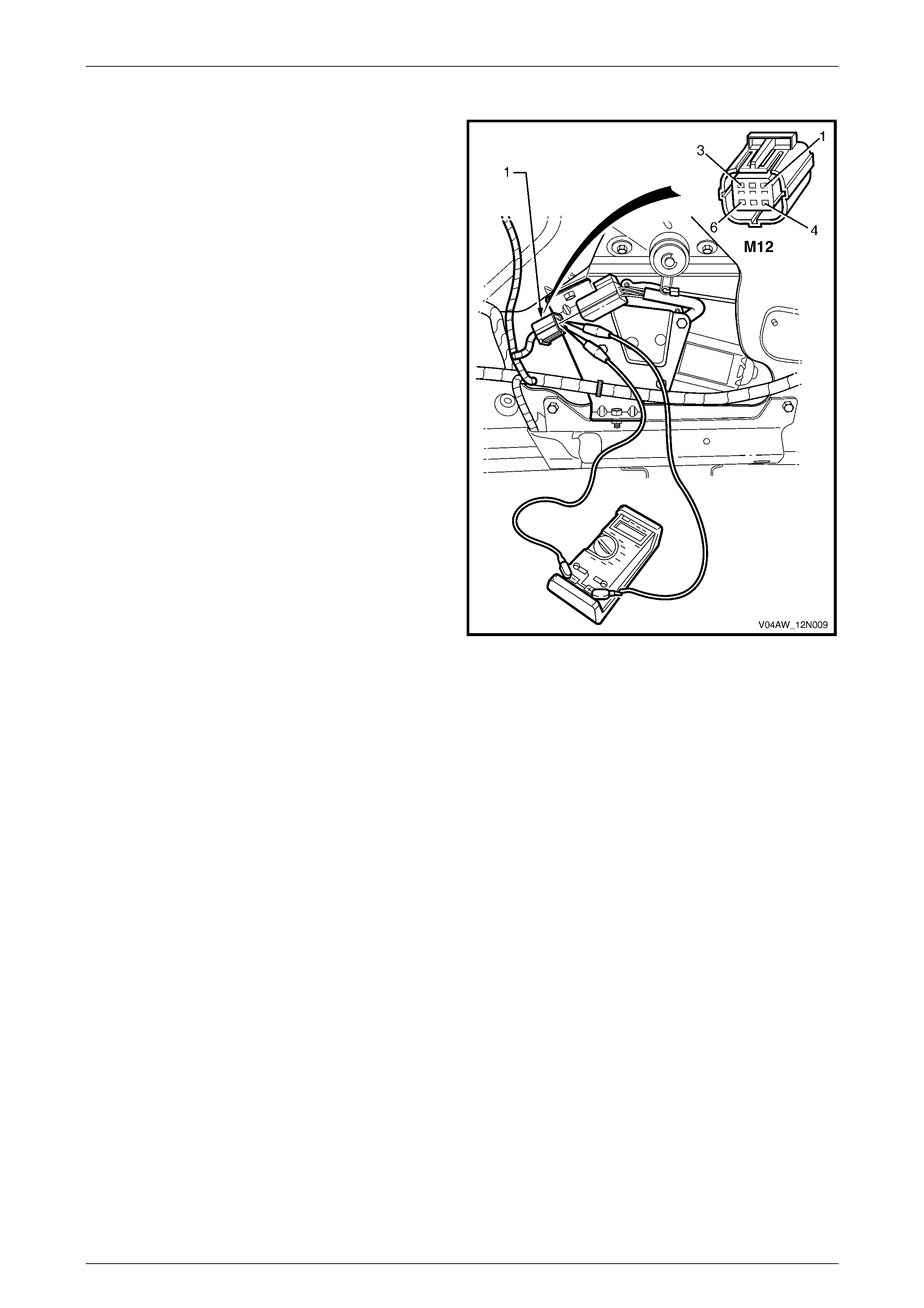
Diagnose Rear Wiper Motor Assembly Wiring
Introduction
The following operation checks the rear wiper motor
assembly wiring at the wiper motor harness connector
M12 – X1 (1) and at the control module harness connector
A122 – X1, as an aid to diagnosing a fault in the wiper motor
assembly system. This test confirms the serviceability of the
rear wiper motor assembly wiring system.
For a complete wiring diagram of the wiper motor assembly
circuits, refer to 2.7 Wiri ng Diagram – Wipers and Washer s
and 2.8 Wiring Diagram – Rear Wiper Control Module.
For connector pin location, refer to 2.9 Connector Diagrams
– Wipers and Washers – Chart A and 2.10 Connector
Diagrams – Wipers and Washers – Chart B.
Figure 12N – 12
Test Description
The following numbers refer to the Steps in the diagnostic chart.
1 Checks whether the fuse F18 between circuits 70 and 243, is serviceable. Isolates whether the fuse is the fault
affecting the battery power circuit supplying the control module.
2 Checks that the rear wiper operates with the liftgate window and liftgate closed.
3 Checks whether there is battery voltage at connector A122 – X1 pin 1. Isolates whether the battery power
circuit 243 is at fault.
4 Checks whether there is battery voltage at connector A122 – X1 pin 3.
5 Checks the wiper and washer control switch. Isolates whether the power supply electrical circuits 391 or 243 or the
wiper switch S247 are at fault.
6 Checks that the control modu l e ground circ uit 650 is serv ic e able.
7 Checks that the rear wiper motor assembly is serviceable.
8 Checks the wiring harness between the connectors M12 – X1 and A122 X1. Isolates whether the circuits 393, 392,
2283, 5456 or 2269 are at fault.
9 Checks that the rear wiper operates in the continuous mode with the rear wiper and rear washer switches ON.
10 Checks whether there is battery voltage at connector A122 – X1 pin 4. Isolates whether the rear wiper control
module A122 is at fault.
11 Checks that the rear wiper relay is serviceable. Isolates whether the power supply electrical circuits 2270, 6721,
227, 550 or 391, or diode V5 are at fault.
12 Checks that the rear wiper operates in the continuous mode with the rear wiper switch ON and the reverse gear
selected.
13 Checks whether the back up fuse F12 between circuits 239 and 3, is serviceable. Isolates whether the fuse is the
fault affecting the battery power circuit supplying the control module.

Wipers, Washers and Horn Page 12N–17
Page 12N–17
14 Checks that the park neutral and back up lamp switch is serviceable.
15 Checks whether there is battery voltage at connector A122 – X1 pin 4. Isolates whether the rear wiper control
module A122, or the power supply electrical circuits 6721, 24, 239 or 3, or diode V5 are at fault.
Notes on the Diagnostic Chart
1 For all wiring harness fault diagnosis, refer to Section 12P Wiring Diagrams.
2 For wiring harness repairs, refer to Section 12P Wiring Diagrams.
3 Refer to Section 12O Fuses, Relays and Wiring Harnesses for harness routeing.
4 If at any time the fault is deemed to be intermittent, refer to Section 12P Wiring Diagrams.
Step Action Yes No
1 1 Check the wiper/washer fuse F18 within the passenger
compartment fuse and relay panel assembly (Refer to Note 3).
Is the fuse serviceable? Go to Step 2.
Replace the fuse.
If the fuse blows
again, check for a
short to ground in
circuit 243,
(refer to Note 2).
2 1 With the liftgate window and liftgate closed, switch the ignition to
ACC or ON position and the rear wiper control switch S247 to the
ON position.
Does the rear wiper operate in the intermittent mode?
Go to Step 9. Go to Step 3.
3 1 Remove the liftgate lower trim panel, refer to Section 1A4 Hood,
Rear Compartment Lid, Liftgate and Endgate.
2 Backprobe the control module connector A122 – X1 pin 1 with a
test lamp (refer to Note 1).
Does the test lamp illuminate? Go to Step 4.
There is a fault in
circuit 243 betw een
control modu le
connector A122 –
X1 pin 1 and
fuse F18.
Repair or replace
circuit 243,
(refer to Note 2).
4 1 Move the rear wiper switch to the ON position.
2 Backprobe the control module connector A122 – X1 pin 3 with a
test lamp (refer to Note 1).
Does the test lamp illuminate?
Go to Step 6. Go to Step 5.
5 1 Test the wiper and washer control switch, refer to Section 12N
Wipers, Washers and Horn in the MY 2003 VY and V2 Series
Service Information.
Is the wiper and washer control switch serviceable?
There is a fault in
circuit 391, or circuit
243 between switch
S247 and fuse F18.
Repair or replace
circuit 391, or 243,
(refer to note 2).
Replace the wiper
and washer control
switch, refer to
Section 12N Wipe rs,
Washers and Horn
in the MY 2003 VY
and V2 Series
Service Information.
6 1 Disconnect the control module connector A122 – X1.
2 With a multimeter, check for continuity of the ground circuit 650
between control module connector A122 – X1 pin 2 and ground
connectors GP13 and GP14 (refer to Note 1).
Is ground circuit 650 serviceable?
Go to Step 7.
There is a fault in
ground circuit 650.
Repair or replace
ground circuit 650
(refer to Note 2).
7 1 Disconnect the rear wiper motor assembly connector M12 – X1.
2 Diagnoses the rear wiper motor assembly M12, refer to
Diagnose Rear Wiper Motor Assembly Operation in this Section.
Is the rear wiper motor assembly serviceable?
Go to Step 8.
Replace the rear
wiper motor
assembly as
described in this
Section.

Wipers, Washers and Horn Page 12N–18
Page 12N–18
Step Action Yes No
8 1 With a multimeter, check for continuity of the wiring harness
between the connectors M12 – X1 and A122 X1 (refer to
Note 1).
Is there continuity between the connectors as follow:
• M12 – X1 pin 1 and A122 X1 pin 5
• M12 – X1 pin 2 and A122 X1 pin 6
• M12 – X1 pin 5 and A122 X1 pin 7
• M12 – X1 pin 3 and A122 X1 pin 9
• M12 – X1 pin 4 and A122 X1 pin 8.
Replace the rear
wiper control
module.
Refer to
2.5 Rear Wiper
Control Module.
There is a fault in
circuits 393, 392,
2283, 5456 or 2269.
Repair or replace
circuits 393, 392,
2283, 5456 or 2269,
(refer to Note 2).
9 1 With the liftgate window and liftgate closed, switch the ignition to
ACC or ON position, move the rear wiper/washer control switch
to the ON position.
Does the rear wiper operate in the continuous mode?
Go to Step 12. Go to Step 10.
10 1 Remove the liftgate lower trim panel, refer to Section 1A4 Hood,
Rear Compartment Lid, Liftgate and Endgate.
2 Backprobe the control module connector A122 – X1 pin 4 with a
test lamp (refer to Note 1).
Does the test lamp illuminate?
Replace the rear
wiper control
module.
Refer to
2.5 Rear Wiper
Control Module.
Go to Step 11.
11 1 Replace the rear wiper relay within the passenger compartment
fuse and relay panel assembly (refer to Note 3).
2 Repeat step 8.
Does the rear wiper operate in the continuous mode? Go to Step 12.
There is a fault in
circuits 2270,6721,
227, 550 or 391, or
diode V5.
Repair or replace
circuits 2270,6721,
227, 550 or 391, or
diode V5,
(refer to Note 2).
12 1 With the liftgate window and liftgate closed, switch the ignition to
ACC position, the rear wiper control switch to the ON position
and engage the reverse gear.
Does the rear wiper operate in the continuous mode?
System serviceable. Go to Step 13.
13 1 Check the backup fuse F12 within the passenger compartment
fuse and relay panel assembly (Refer to note 3).
Is the fuse serviceable? Go to Step 14.
Replace the fuse.
If the fuse blows
again, check for a
short to ground in
circuit 239,
(refer to Note 2).
14 1 Check the park neutral and back up lamp switch, refer to
Section 6C3 2A Diagnostic Tables – GEN III V8 Engine in the
MY 2003 VY and V2 Series Service Information.
Is the park neutral and back up lamp switch serviceable? Go to Step 15.
Replace the park
neutral and back up
lamp switch, refer to
Section 7C4 Hydra-
matic 4L60-E
Automatic
Transmission – On-
vehicle Servicing in
the MY 2003 VY
and V2 Series
Service Information.

Wipers, Washers and Horn Page 12N–19
Page 12N–19
Step Action Yes No
15 1 If required, remove the liftgate lower trim panel, refer to Section
1A4 Hood, Rear Compartment Lid, Liftgate and Endgate.
2 Backprobe the control module connector A122 – X1 pin 4 with a
test lamp (refer to Note 1).
Does the test lamp illuminate?
Replace the rear
wiper control
module.
Refer to
2.5 Rear Wiper
Control Module.
There is a fault in
circuits 6721, 24,
239 or 3, or
diode V5.
Repair or replace
circuits 6721, 24,
239 or 3, or
diode V5,
(refer to Note 2).
When all diagnosis and repairs are completed, check the system for correct operation.
Diagnose Rear Wiper Motor Assembly Operation
Introduction
The rear wiper motor assembly is attached to the liftgate
assembly, and drives the rear wiper arm assembly directly
through the motor shaft. This test confirms the serviceability
of the rear wiper motor assembly, and diagnoses the rear
wiper forward and reverse drive functions. For pin
numbering within the connector M12 – X1 (1) refer to
Figure 12N – 13.
NOTE
If there is a fault in the rear wiper system, and
the following test proves that the rear wiper
motor assembly is serviceable, refer to Diagnose
Rear Wiper Motor Assembly Wiring as detailed
in this Section.
When performing the following test lift the rear wiper arm
away from the liftgate window and keep it attached to the
motor spigot. While the motor is operating, monitor the
movement of the rear wiper arm as a guide for the park
positions, refer to 1.1 Rear Wiper Assembly.
Using a digital multimeter, monitor the readings to determine
if the motor park limit switches are closing when required.
Figure 12N – 13
Test Description
The following numbers refer to the Steps in the diagnostic chart.
1 Checks the rear wiper motor assembly forward operation. Isolates whether the circuit within the rear wiper motor
assembly is serviceable between the motor connector M12 – X1 pin 1 and pin 2.
2 Checks the rear wiper motor assembly reverse operation. Isolates whether the circuit within the rear wiper motor
assembly is serviceable between the motor connector M12 – X1 pin 2 and pin 1.
3 Checks the rear wiper motor assembly reverse park limit switch operation. Isolates whether the circuit within the
rear wiper motor assembly is serviceable between the motor connector M12 – X1 pin 3 and pin 5.
4 Checks the rear wiper motor assembly forward park limit switch operation. Isolates whether the circuit within the
rear wiper motor assembly is serviceable between the motor connector M12 – X1 pin 4 and pin 5.

Wipers, Washers and Horn Page 12N–20
Page 12N–20
Step Action Yes No
1 1 Remove the rear wiper fuse F18 from the passenger
compartment fuse and relay panel assembly. Refer to
Section 12O Fuses, Relays and Wiring Harnesses.
2 Remove the liftgate window lower garnish and the liftgate lower
trim panel, refer to Section 1A4 Hood, Rear Compartment Lid,
Liftgate and Endgate.
3 Disconnect the wiring harness connector M12.
4 Connect a jumper lead from the vehicle battery negative terminal
to the motor connector M12 – X1 pin 2.
5 Connect a jumper lead from the vehicle battery positive terminal
to the motor connector M12 – X1 pin 1.
Does the rear wiper motor assembly operate in the forward direction?
Go to Step 2.
Replace the rear
wiper motor
assembly as
detailed in this
Section.
2 1 Connect a jumper lead from the vehicle battery negative terminal
to the motor connector M12 – X1 pin 1.
2 Connect a jumper lead from the vehicle battery positive terminal
to the motor connector M12 – X1 pin 2.
Does the wiper motor assembly operate in the reverse direction?
Go to Step 3.
Replace the rear
wiper motor
assembly as
detailed in this
Section.
3 1 Connect a jumper lead from the vehicle battery negative terminal
to the motor connector M12 – X1 pin 2.
2 Connect a jumper lead from the vehicle battery positive terminal
to the motor connector M12 – X1 pin 1.
3 With the rear wiper motor assembly operating in the forward
direction, using a multimeter probe with the positive lead to the
connector M12 – X1 pin 3 and the negative lead to M12 – X1
pin 5.
Does the multimeter indicate continuity when the motor reverse park
limit switch closes (at rear wiper arm full wipe sweep position)?
Go to Step 4.
Replace the rear
wiper motor
assembly as
detailed in this
Section.
4 1 With the rear wiper motor assembly operating in the forward
direction, using a multimeter probe with the positive lead to the
connector M12 – X1 pin 4 and the negative lead to M12 – X1
pin 5.
Does the multimeter indicate continuity when the motor forward park
limit switch closes (at rear wiper arm wipe sweep start)?
NOTE
After this test has been completed, operate the rear wiper
for a wipe cycle and turn the rear wiper switch to OFF for
the rear wiper arm to park in the offscreen park position.
The rear wiper
motor asse mbly is
serviceable.
Replace the rear
wiper motor
assembly as
detailed in this
Section.
When all diagnosis and repairs are completed, check the system for correct operation.
Wiper Motor Limit Switches Malfunction Table
The following table provides a guide as to how the rear wiper arm will behave if the rear wiper motor park limit switches
contacts malfunction.
Switch Position Rear Wiper Motor Park Limit Switch Fail Rear Wiper and Motor Action
Rear wiper switch
from OFF to ON Forward park limit sw itch
or
Reverse park limit switch
or
Forward and reverse park limit switches
The rear wiper arm may have an initial 9 second
delay in the on-screen park position after the first
cycle.
Then the rear wiper motor and rear wiper arm
operate continuously.

Wipers, Washers and Horn Page 12N–21
Page 12N–21
Switch Position Rear Wiper Motor Park Limit Switch Fail Rear Wiper and Motor Action
Rear wiper switch
from ON to OFF Forward park limit sw itch
or
Reverse park limit switch
or
Forward and reverse park limit switches
The rear wiper motor and rear wiper arm continue to
operate continuously.
After 12 seconds have elapsed, the rear wiper
control module cuts off power supply to the rear
wiper motor and the rear wiper arm stops anywhere
on the liftgate window.
Rear washer switch
from OFF to ON Forward park limit sw itch
or
Reverse park limit switch
The rear wiper motor and rear wiper arm operate
continuously.
Rear washer switch
from OFF to ON Forward and reverse park limit switches The rear wiper arm may have an initial 9 second
delay in the on-screen park position after the first
cycle.
Then the rear wiper motor and rear wiper arm
operate continuously.
Rear washer switch
from ON to OFF Forward park limit sw itch
or
Reverse park limit switch
or
Forward and reverse park limit switches
The rear wiper motor and rear wiper arm continue to
operate continuously.
After 12 seconds have elapsed, the rear wiper
control module cuts off power supply to the rear
wiper motor and the rear wiper arm stops anywhere
on the liftgate window.
Diagnose Rear Wiper Assembly and Liftgate Interface Operation
Introduction
The following diagnosis checks the rear wiper motor assembly operation combined with the state (open or close) of the
liftgate window and liftgate assembly. The rear wiper control module controls this operation by receiving an input signal
from the liftgate window switch S69 when the liftgate window is open and from the liftgate switch S189 when the liftgate
is open and energises the liftgate window actuator Y7 to open the liftgate window when the rear wiper arm is in the
offscreen park position. For a description of the liftgate assembly and its components, refer to Section 1A4 Hood, Rear
Compartment Lid, Liftgate and Endgate.
This test confirms the serviceability of the wiring system between the rear wiper control module A122 and the liftgate
assembly. For a complete wiring diagram of the rear wiper control module circuits, refer to 2.8 Wiring Diagram – Rear
Wiper Control Module. For connector pin location, refer to 2.9 Connector Diagrams – Wipers and Washers – Chart A
and 2.10 Connector Diagrams – Wipers and Washers – Chart B.
Test Description
The following numbers refer to the Steps in the diagnostic chart.
1 Checks if the liftgate window opens with the rear wiper control switch S247 in the OFF position.
2 Checks that liftgate window actuator Y7 is serviceable.
3 Checks the liftgate window actuator harness between connectors A122 – X1 pin 12 and Y7 – X1 pin A. Isolates if
the circuit 6188 is at fault.
4 Checks the liftgate window actuator harness between connectors Y7 – X1 pin B and ground. Isolates if the circuit
650 is at fault.
5 Checks if the rear wiper motor operates with the liftgate window open and the liftgate closed.
6 Checks that liftgate window switch S69 is serviceable.
7 Checks the liftgate window switch harness between connectors A122 – X1 pin 10 and S69 – X1 pin 1. Isolates if
the circuits 737 or 744 are at fault.
8 Checks the liftgate window switch harness between connector S69 – X1 pin 2 and ground. Isolates if the circuit 650
is at fault.
9 Checks if the rear wiper motor operates with the liftgate window closed and the liftgate open.
10 Checks that liftgate switch S189 is serviceable.
11 Checks the liftgate switch harness between connectors A122 – X1 pin 10 and S189 – X1 pin A. Isolates if the
circuit 737 is at fault.

Wipers, Washers and Horn Page 12N–22
Page 12N–22
Notes on the Diagnostic Chart
1 For all wiring harness fault diagnosis, refer to Section 12P Wiring Diagrams.
2 For wiring harness repairs, refer to Section 12P Wiring Diagrams.
3 Refer to Section 12O Fuses, Relays and Wiring Harnesses for harness routeing.
4 If at any time the fault is deemed to be intermittent, refer to Section 12P Wiring Diagrams.
Step Action Yes No
1 1 With the liftgate window and liftgate closed, switch the ignition to
ACC or ON position and the rear wiper control switch to the OFF
position.
Does the liftgate window open when activated?
Go to Step 5. Go to Step 2.
2 1 Remove the liftgate lower trim panel, refer to Section 1A4,
2.2 Liftgate Lower Trim Panel.
2 Check the liftgate window actuator Y7, refer to Section 1A4,
2.4 Liftgate Window Release Assembly.
Is the liftgate window actuator Y7 serviceable?
Go to Step 3.
Replace the liftgate
window actuator Y7
refer to Section 1A4,
2.4 Liftgate Window
Release Assembly.
3 1 With a multimeter, check the liftgate window actuator harness for
continuity between connectors A122 – X1 pin 12 and Y7 – X1
pin A (refer to Note 1).
Is there continuity? Go to Step 4.
There is a fault in
circuit 6188
Repair or replace
circuit 6188,
(refer to Note 2).
4 1 With a multimeter, check the liftgate window actuator ground
circuit for continuity between connector Y7 – X1 pin B and
X118_GP12 (refer to Note 1).
Is there continuity?
Replace the rear
wiper control
module .
Refer to
2.5 Rear Wiper
Control Module.
There is a fault in
ground circuit 650
Repair or replace
ground circuit 650
(refer to Note 2).
5 1 With the liftgate window open and the liftgate closed, switch the
ignition to ACC or ON position and the rear wiper control switch
S247 to the ON position.
Does the rear wiper operate?
Go to Step 6. Go to Step 9.
6 1 Remove the liftgate lower trim panel, refer to Section 1A4,
2.2 Liftgate Lower Trim Panel.
2 Check the liftgate window switch S69, refer to Section 1A4 Hood,
Rear Compartment Lid, Liftgate and Endgate.
Is the liftgate window switch S69 serviceable?
Go to Step 7.
Replace the liftgate
window switch S69
refer to Section 1A4,
2.4 Liftgate Window
Release Assembly.
7 1 With a multimeter, check the liftgate window switch S69 harness
for continuity between connectors A122 – X1 pin 10 and S69 –
X1 pin 1 (refer to Note 1).
Is there continuity? Go to Step 8.
There is a fault in
circuits 737 or 744.
Repair or replace
circuits 737 or 744
(refer to Note 2).
8 1 With a multimeter, check the liftgate window switch S69 ground
circuit for continuity between connector S69 – X1 pin 2 and
X118_GP12 (refer to Note 1).
Is there continuity?
Replace the rear
wiper control
module A122.
Refer to
2.5 Rear Wiper
Control Module.
There is a fault in
ground circuit 650
Repair or replace
ground circuit 650
(refer to Note 2).
9 1 With the liftgate window closed and the liftgate open, switch the
ignition to ACC or ON position and the rear wiper control switch
S247 to the ON position.
Does the rear wiper operate?
Go to Step 10. System serviceable.

Wipers, Washers and Horn Page 12N–23
Page 12N–23
Step Action Yes No
10 1 Check the liftgate switch S189, refer to Section 1A4 Hood, Rear
Compartment Lid, Liftgate and Endgate in the MY 2003 VY and
V2 Series Service Information.
Is the liftgate window switch S189 serviceable? Go to Step 11.
Replace the liftgate
switch S189 refer to
Section 1A4 Hood,
Rear Compartment
Lid, Liftgate and
Endgate in the
MY 2003 VY and V2
Series Service
Information.
11 1 Remove the liftgate lower trim panel, refer to Section 1A4,
2.2 Liftgate Lower Trim Panel.
2 With a multimeter, check the liftgate switch S189 harness for
continuity between connectors A122 – X1 pin 10 and S189 – X1
pin A (refer to Note 1).
Is there continuity?
Replace the rear
wiper control
module A122.
Refer to
2.5 Rear Wiper
Control Module.
There is a fault in
circuits 737.
Repair or replace
circuits 737,
(refer to Note 2).
When all diagnosis and repairs are completed, check the system for correct operation.

Wipers, Washers and Horn Page 12N–24
Page 12N–24
Remove
Ensure that the rear w iper motor assembly is
in the park position.
1 Remove the rear wiper fuse F18 from the passenger
compartment fuse and relay panel assembly. Refer to
Section 12O Fuses, Relays and Wiring.
2 Remove the rear wiper arm assembly, refer to
2.3 Rear Wiper Arm Assembly in this section.
3 Remove the cover (1), nut (2), cap (3) and outer
spacer (4) from the rear wiper motor spigot (5).
Figure 12N – 14
4 Remove the liftgate window lower garnish and the
liftgate lower trim panel, refer to Section 1A4,
2.2 Liftgate Lower Trim Panel.
5 Unclip the liftgate harness (1) from the motor attaching
bracket (2).
6 Disconnect the motor wiring harness connector (3).
7 Remove the two screws (4) and remove the motor
assembly (5) with the attaching bracket, from the
liftgate.
Figure 12N – 15
Wipers, Washers and Horn Page 12N–25
Page 12N–25
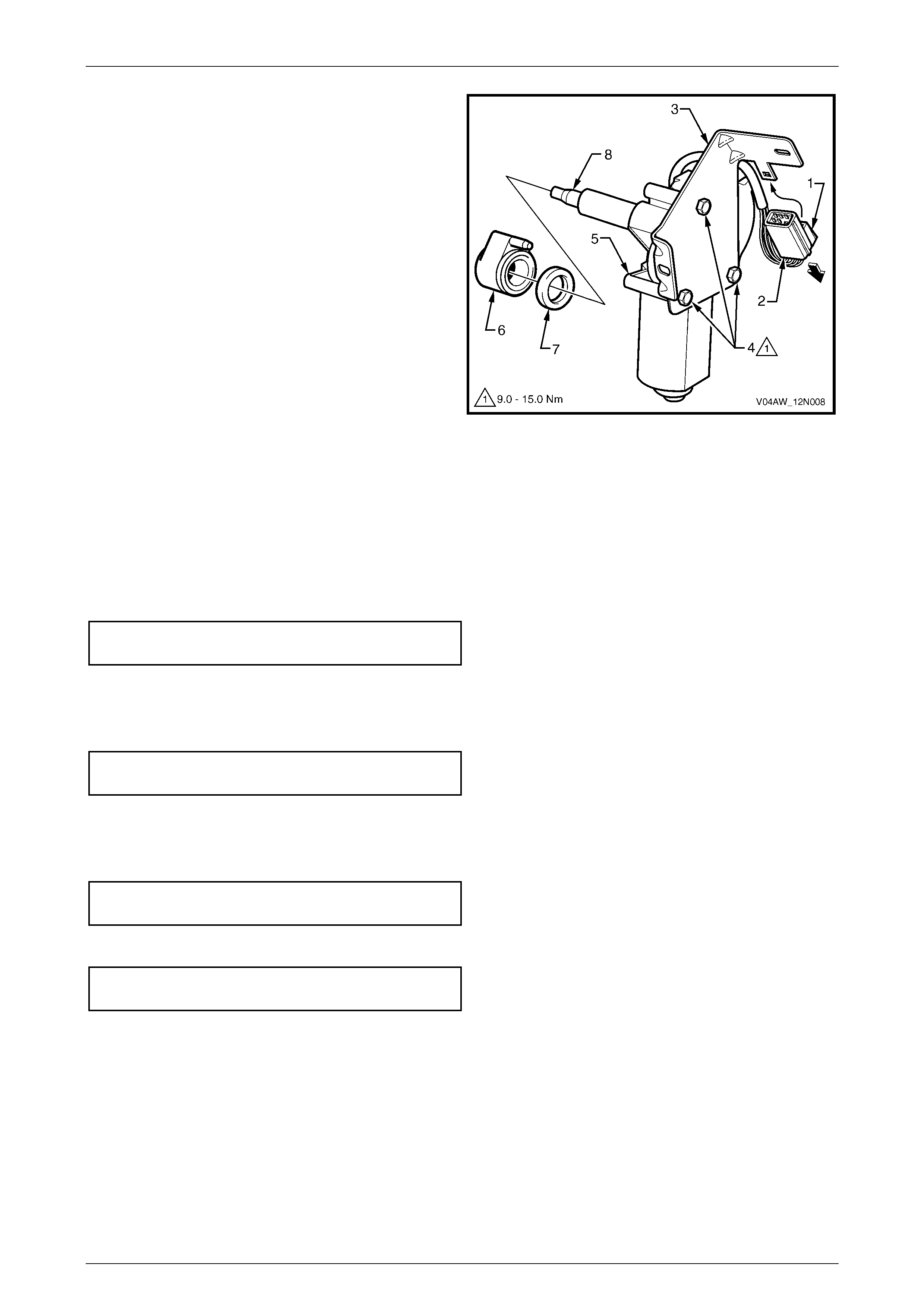
8 Press the tab (1) and pull to remove the wiring
connector (2) from the motor attaching bracket (3).
9 Remove the three screws (4) and separate the rear
wiper motor (5) from the attaching bracket.
10 Remove the inner spacer (6) and the cap (7) from the
rear wiper motor spigot (8).
Figure 12N – 16
Reinstall
Installation of the rear wiper motor assembly is the reverse of the removal procedure, noting the following:
1 Ensure that the cap (7) and the inner spacer (6) are fitted correctly onto the rear wiper motor spigot (8), refer to
Figure 12N – 16.
2 Ensure that the rear wiper motor (5) is securely fitted to the attaching bracket (3). Tighten the three rear window
wiper motor assembly attaching screws (4) to the specified torque.
Rear window wiper motor assembly
attaching screw torque specification......... 9.0 – 15.0 Nm
3 Ensure that the wiring connector (2) is secured to the attaching bracket.
4 Ensure that the rear wiper motor assembly and the attaching bracket are securely attached to the liftgate. Tighten
the two rear window wiper motor bracket attaching screws (4) to the specified torque. Refer to Figure 12N – 15.
Rear window wiper motor bracket
attaching screw torque specification......... 6.0 – 14.0 Nm
5 Ensure that the motor wiring harness connector (3) is securely connected.
6 Ensure that the outer spacer (4), cap (3) and nut (2) are fitted correctly onto the rear wiper motor spigot (5), refer to
Figure 12N – 14. Tighten the rear window wiper motor assembly attaching nut to the specified torque.
Rear window wiper motor assembly
attaching nut torque specification............... 4.0 – 6.0 Nm
7 Tighten the rear window wiper arm assembly attaching nut (6) to the correct torque specification.
Rear window wiper arm assembly
attaching nut torque specification........... 10.0 – 14.0 Nm
Wipers, Washers and Horn Page 12N–26
Page 12N–26
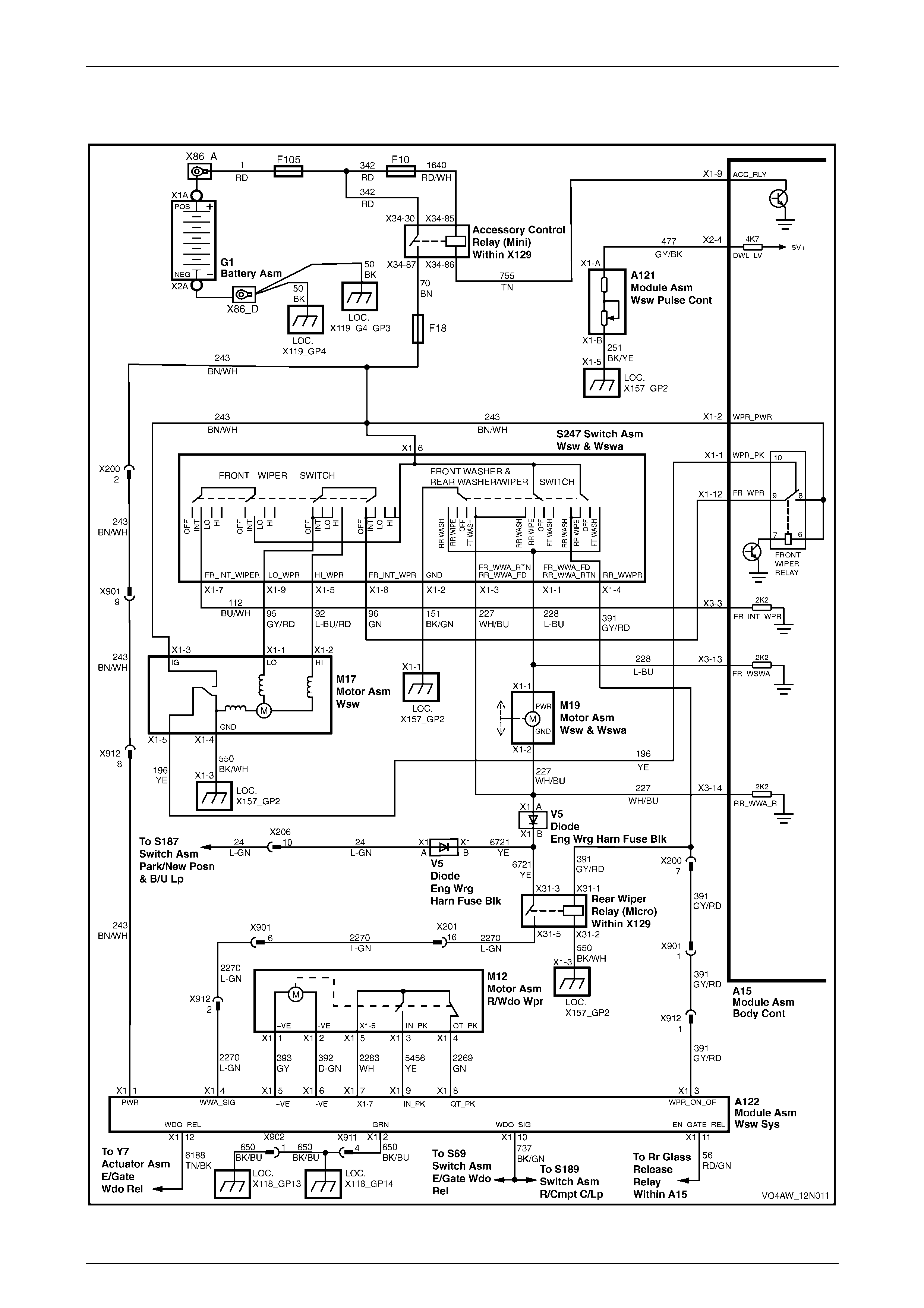
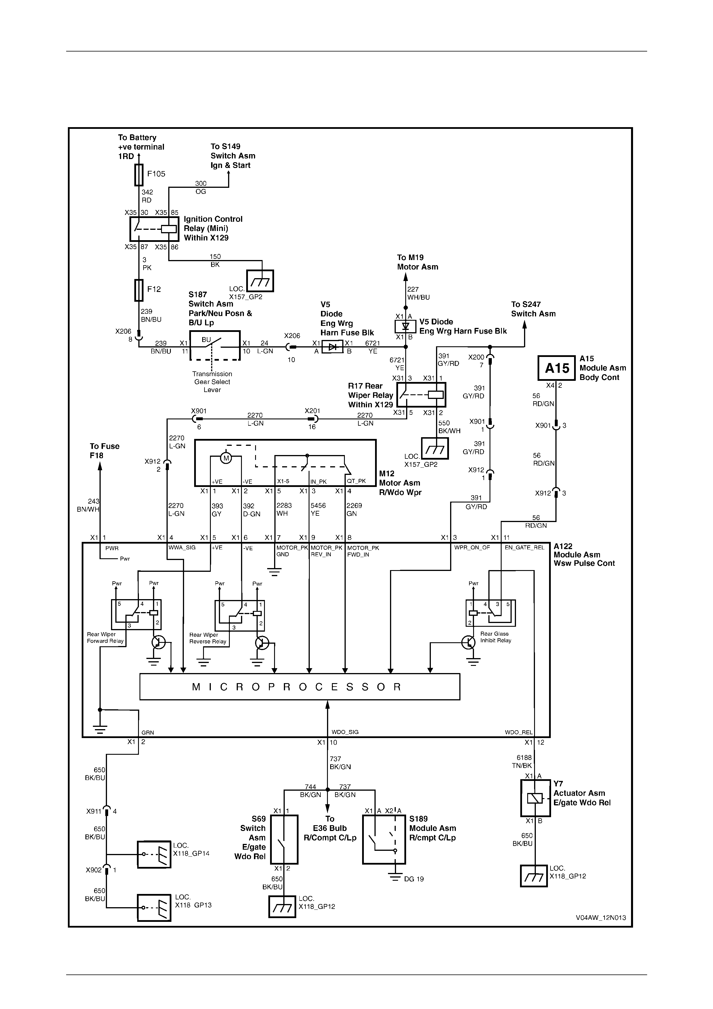
2.7 Wiring Diagram – Wipers and Washers
Figure 12N – 17
Wipers, Washers and Horn Page 12N–27
Page 12N–27
2.8 Wiring Diagram – Rear Wiper Control
Module
Figure 12N – 18
Wipers, Washers and Horn Page 12N–28
Page 12N–28
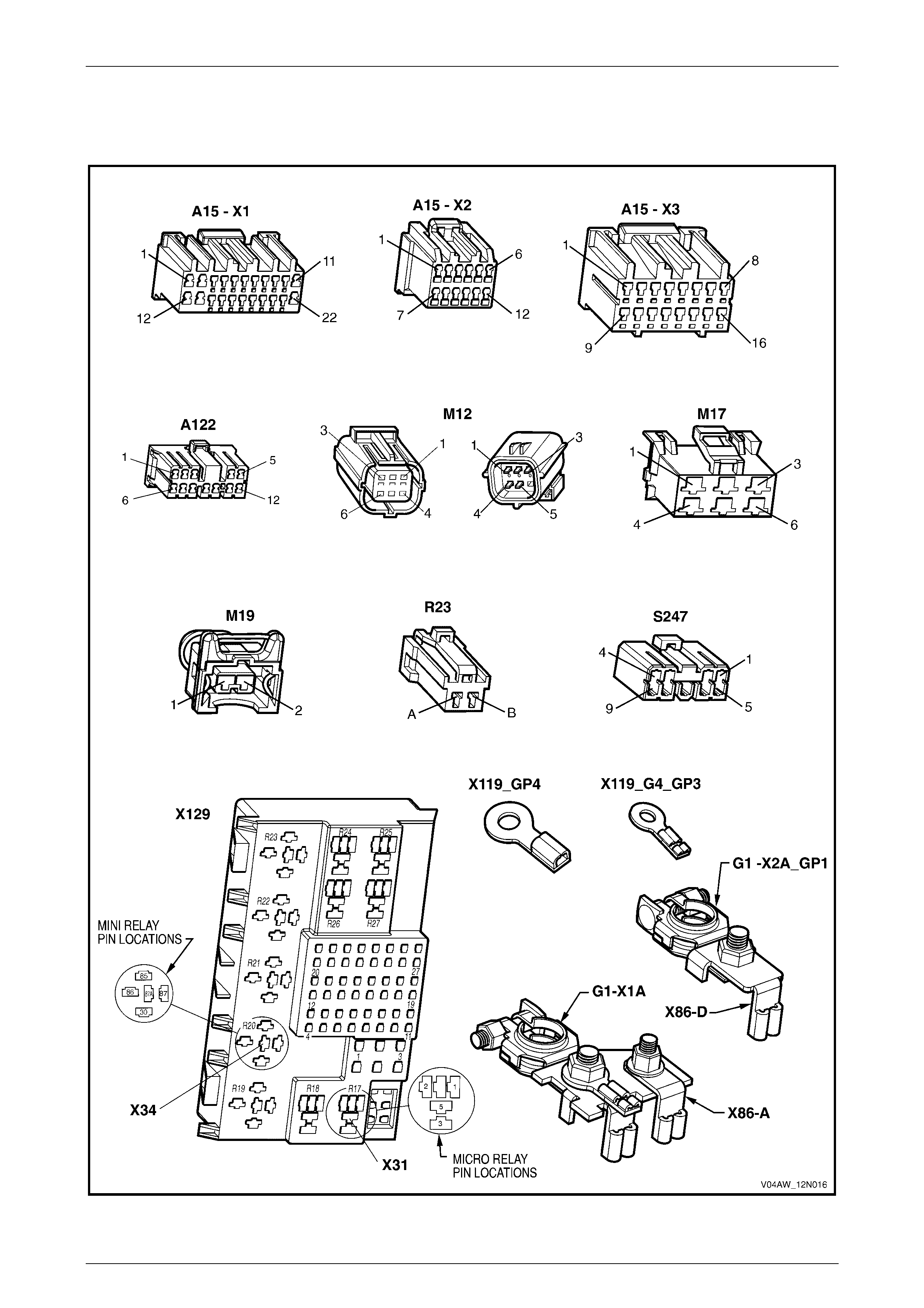
2.9 Connector Diagrams – Wipers and
Washers – Chart A
Figure 12N – 19
Wipers, Washers and Horn Page 12N–29
Page 12N–29
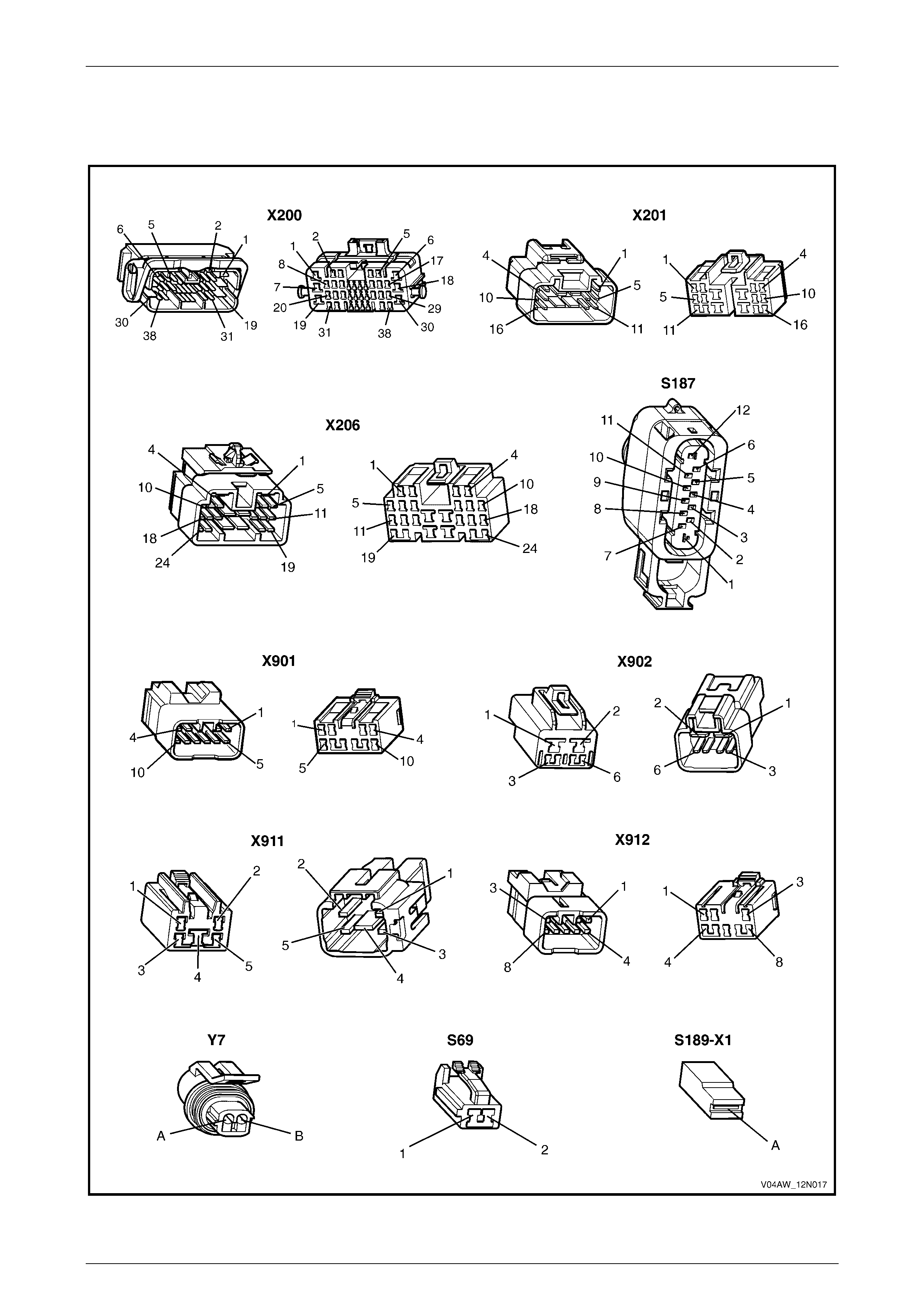
2.10 Connector Diagrams – Wipers and
Washers – Chart B
Figure 12N – 20

Wipers, Washers and Horn Page 12N–30
Page 12N–30
3 Torque Wrench Specifications
Rear window wiper arm assembly attaching nut .......................10.0 – 14.0 Nm
Rear window wiper ramp attaching screw......................................1.0 – 2.0 Nm
Rear window wiper control module
support bracket attaching screw..................................................6.0 – 14.0 Nm
Rear window wiper motor assembly attaching screw .................. 9.0 – 15.0 Nm
Rear window wiper motor bracket attaching screw......................6.0 – 14.0 Nm
Rear window wiper motor assembly attaching nut.......................6.0 – 14.0 Nm