
HVAC Occupant Climat e Control (Auto A/ C) – Diagnostic s Page 2F–1
Page 2F-1
Section 2F
HVAC Occupant Climate Control (Auto A/C)
– Diagnostics
ATTENTION
Before performing any Service Operation or other procedure described in this Section, refer to Section 00
Warnings, Cautions and Notes for correct workshop practices with regard to safety and/or property damage.
1 General Information............................................................................................................................... 2
2 Diagnostics............................................................................................................................................. 3
2.1 Diagnostic Trouble Codes.....................................................................................................................................3
3 Wiring Diagrams .................................................................................................................................... 4
Connectors .............................................................................................................................................................5
Connectors continued...........................................................................................................................................6
Connectors continued...........................................................................................................................................7
Wiring Diagram.......................................................................................................................................................8
Techline
Techline
Techline

HVAC Occupant Climat e Control (Auto A/ C) – Diagnostic s Page 2F–2
Page 2F-2
1 General Information
The diagnostic information of the HVAC Occupant Climate Control (Auto A/C) system as fitted to MY 2004 AWD W agon
vehicles carries over from the information provided in Section 2F HVAC Occupant Climate Control (Auto A/C) –
Diagnostics in the MY 2003 VY and V2 Series Service Information, noting the following:
• The TECH 2 model selection procedure is as detailed in this Section.
• All MY 2004 AWD Wagon vehicles combine an OCC (Auto A/C) HVAC system with a high power (430 W) engine
cooling fan system The wiring diagram information in this Section reflects this combination.
For additional diagnosis information on MY 2004 AWD Wagon vehicles, which is not contained within this Section, refer
to following Sections as required:
• Section 2C HVAC Climate Control (Manual A/C) – Service and Diagnosis in the MY 2003 VY and V2 Series
Service Information, for HVAC components and service procedures common to Manual A/C.
• Section 2F HVAC Occupant Climate Control (Auto A/C) – Diagnostics in the MY 2003 VY and V2 Series Service
Information, for diagnostic information applicable only to OCC (Auto A/C).
HVAC Occupant Climat e Control (Auto A/ C) – Diagnostic s Page 2F–3
Page 2F-3
2 Diagnostics
2.1 Diagnostic Trouble Codes
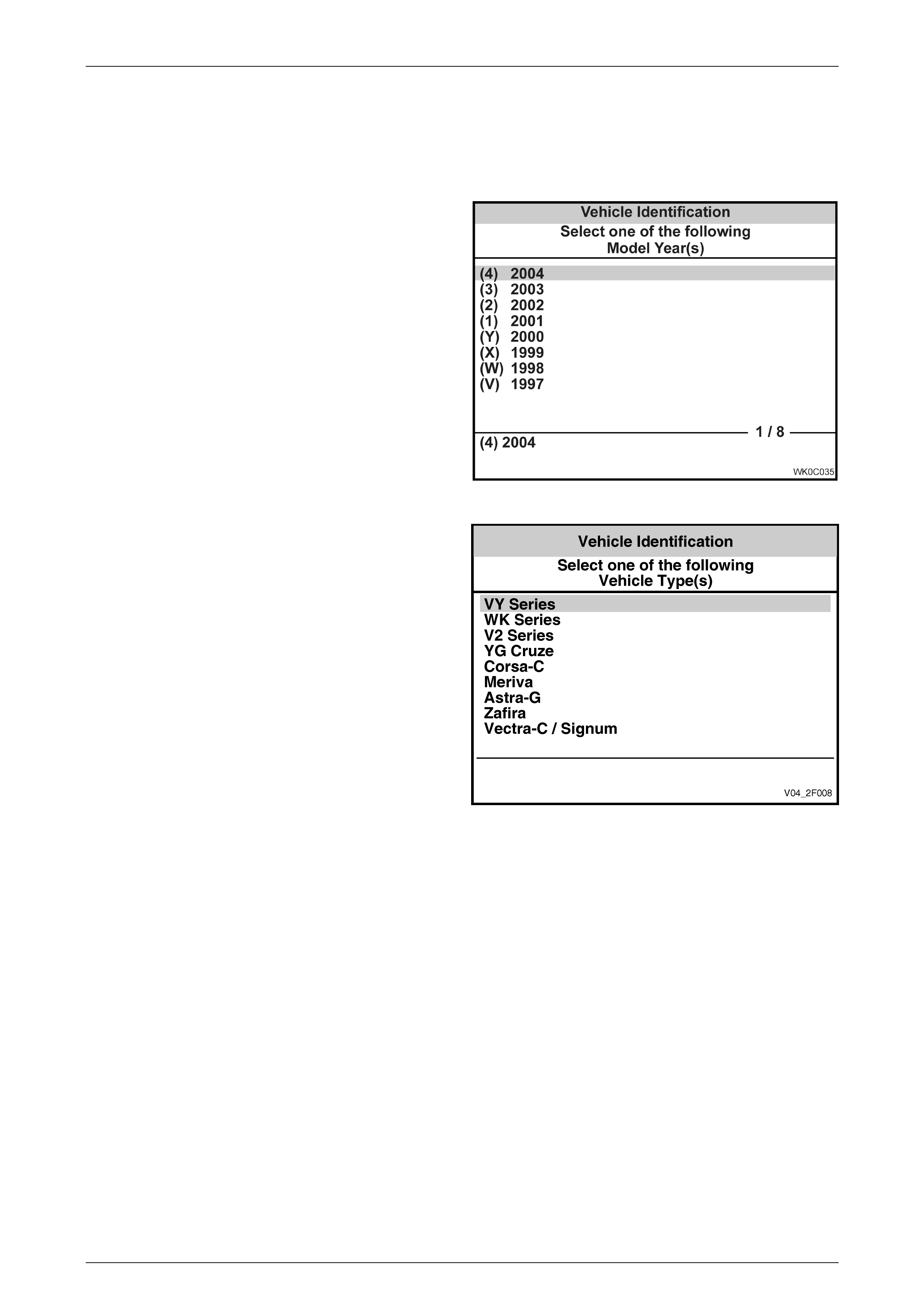
The diagnost ic infor mat ion ac c ess procedures are a
carry over from the MY 2003 VY Series except that the
Model Year selection on TECH 2 is now (4) 2004.
Figure 2F – 1
The Vehicle Type selection is VY Series.
Figure 2F – 2
HVAC Occupant Climat e Control (Auto A/ C) – Diagnostic s Page 2F–4
Page 2F-4
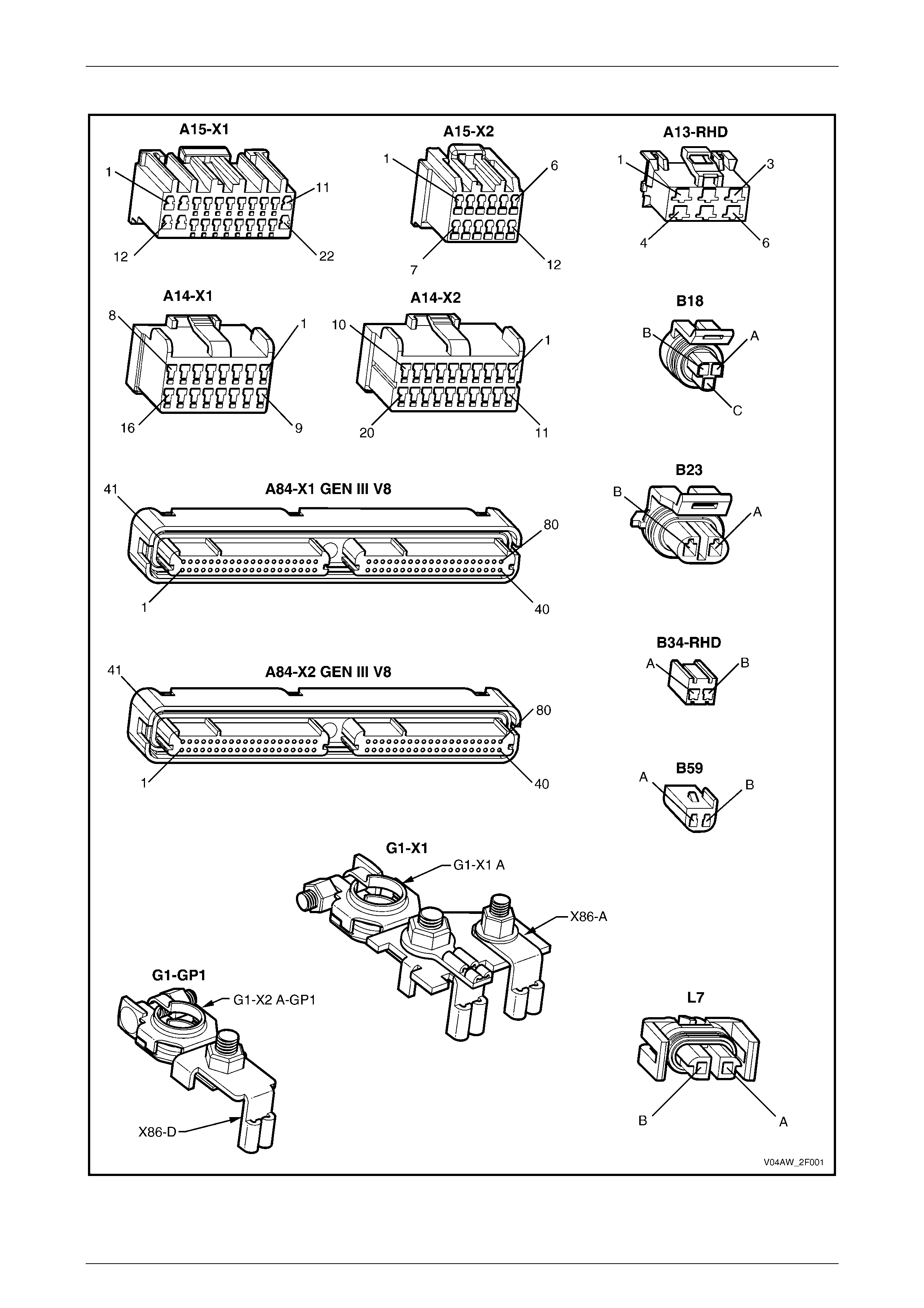
3 Wiring Diagrams
The following figures provide electrical connector diagrams and a wiring diagram applicable to HVAC Occupant Climate
Control (Auto A/C) systems as fitted to MY 2004 AWD Wagon vehicle s . When diagnosin g circuit faults, these di agrams
should be used in conjunction with the diagnostic chart circuit diagrams provided in Section 2F HVAC Occupant Climate
Control (Auto A/C) – Diagnostics in the MY 2003 VY and V2 Series Service Information. The content of these figures is
as follows:
• Electrical connectors (A13 – L7) – refer to Figure 2F – 3
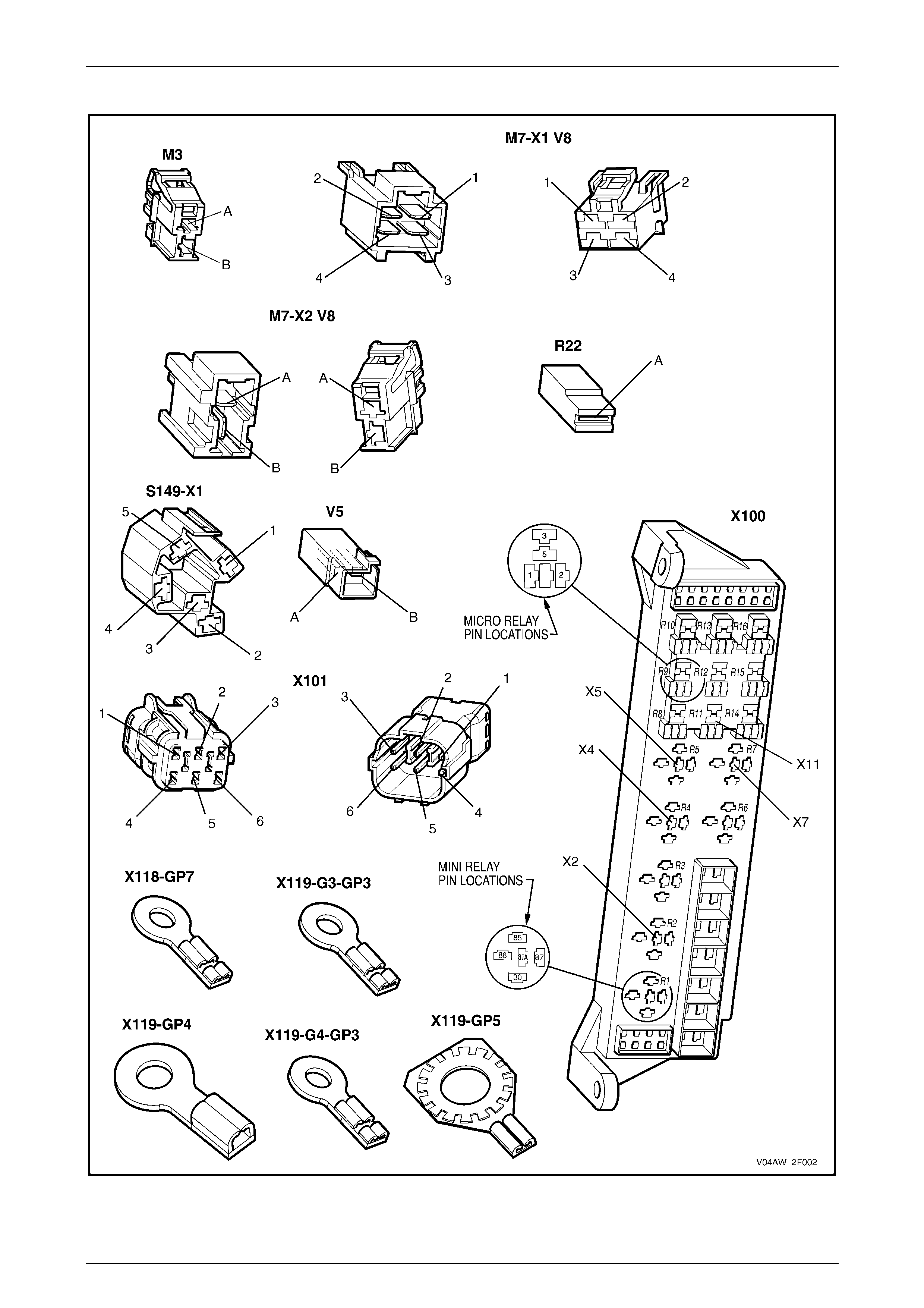
• Electrical connectors continued (M3 – X119) – refer to Figure 2F – 4
• Electrical connectors continued (X126 – Y37) – refer to F igure 2F – 5
• Wiring diagram – refer to Figure 2F – 6
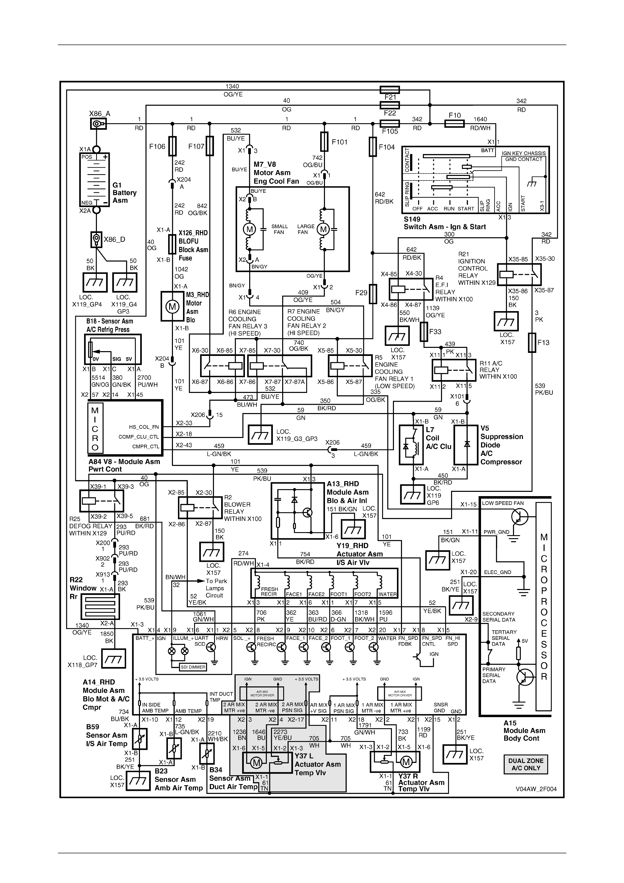
In the following wiring diagram (Figure 2F – 6) all compo nent s are described and dis play ed in accordance to the
Integrated Vehicle Electrical Design (IVED) standard as applied to MY 2004 AWD Wagon vehicles. To assist in wiring
diagram interpretation, refer to the following table:
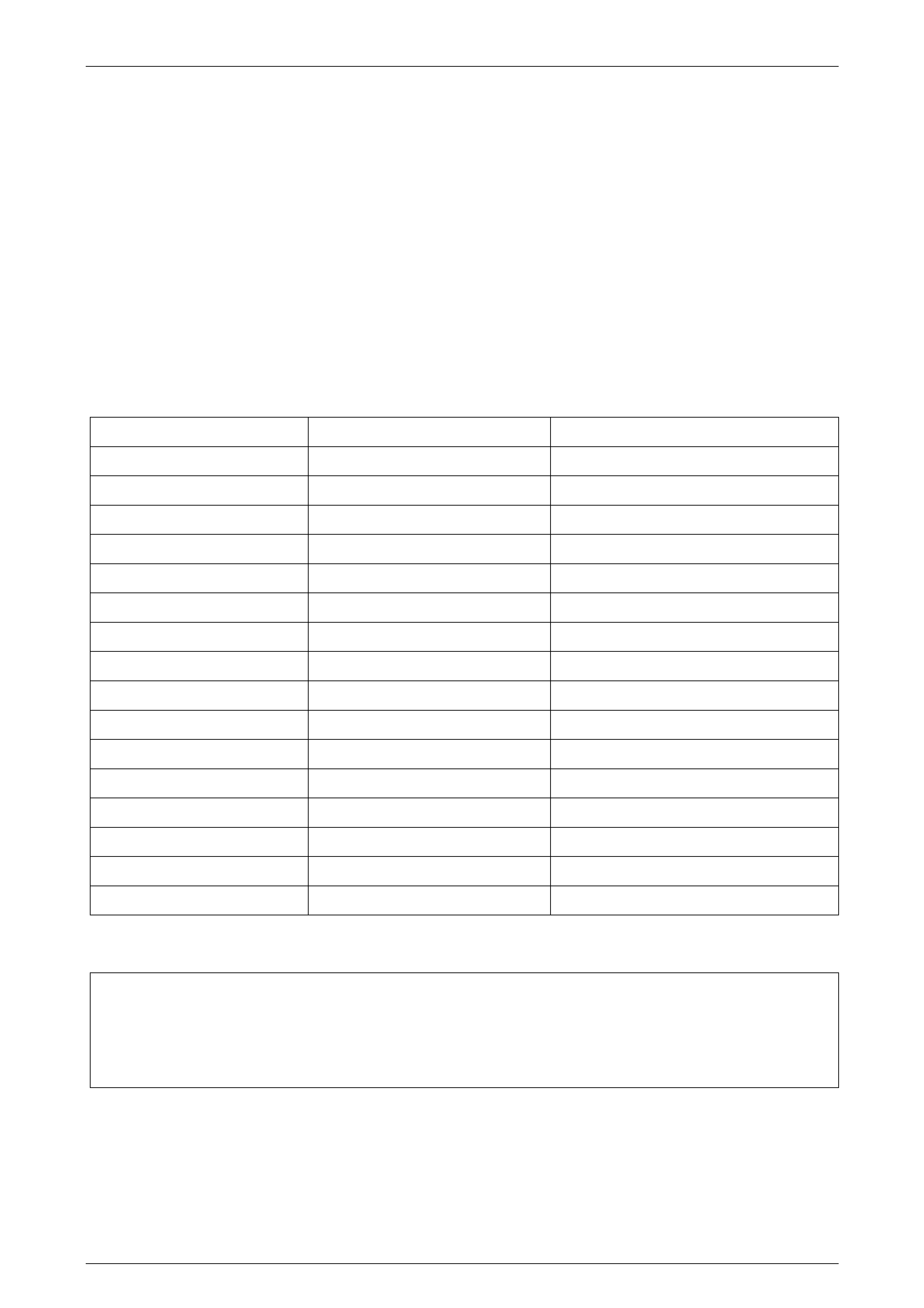
IVED Description IVED Component Identification Common Description
Module Asm Blo & Air Inl A13_RHD Blower Motor Resistor
Module Asm Blo & A/C Cmpr A14_RHD OCC Control Module for RHD models
Module Asm Body Cont A15 Body Control Module
Module Asm Pwrt Cont A84 GEN III V8 Powertrain Control Module
Sensor Asm A/C Refrig Press B18 A/C Pressure Transducer
Sensor Asm Amb Air Temp B23 Ambient Air Temperature Sensor
Sensor Asm Duct Air Temp B34_RHD Evaporative Temperatu re Sensor
Sensor Asm I/S Air Temp B59 In-car Temperature Sensor
Coil A/C Clu L7 Compressor Clu tch
Motor Asm Blo M3_RHD Blower Motor
Motor Asm Eng Cool Fan M7_V8 GEN III V8 Cooling Fan System
Window Rr R22 Heated Rear Window
Switch Asm Ign & Start S149 Ignition Switch
Actuator Asm I/S Air Vlv Y19_RHD Solenoid Pack
Actuator Asm Temp Vlv Y37 L Passenger’s Air Mix Door Motor
Actuator Asm Temp Vlv Y37 R Driver’s Air Mix Door Motor
The following table lists the IVED standard wire colour abbreviations:
BK Black D-GN Dark green L-GN Light green RD Red
BU Blue GN Green OG Orange TN Tan
BN Brown GY Grey PK Pink WH White
D-BU Dark blue L-BU Light blue PU Purple YE Yellow
NOTE
For electrical connector locations and
additional wiring diagram information refer to
Section 12P Wiring Diagrams.
HVAC Occupant Climat e Control (Auto A/ C) – Diagnostic s Page 2F–5
Page 2F-5
Connectors
Figure 2F – 3
HVAC Occupant Climat e Control (Auto A/ C) – Diagnostic s Page 2F–6
Page 2F-6
Connectors continued
Figure 2F – 4
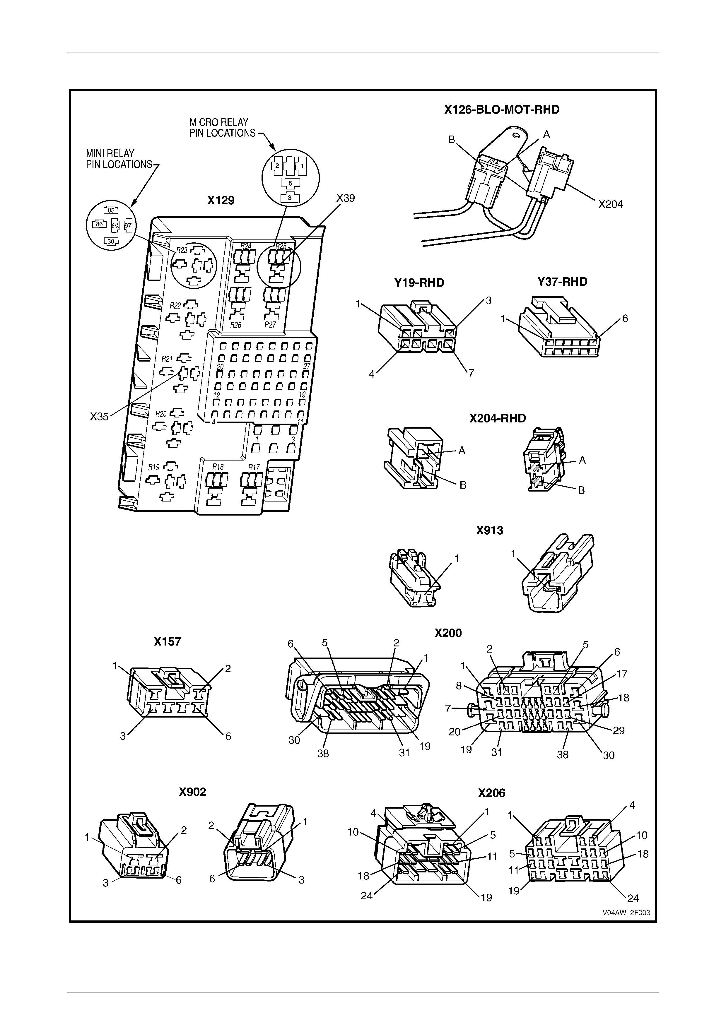
HVAC Occupant Climat e Control (Auto A/ C) – Diagnostic s Page 2F–7
Page 2F-7
Connectors continued
Figure 2F – 5
HVAC Occupant Climat e Control (Auto A/ C) – Diagnostic s Page 2F–8
Page 2F-8
Wiring Diagram
Figure 2F – 6