Rear Suspension Page 4A-1
Page 4A-1
Section 4A
Rear Suspension
ATTENTION
Before performing any Service Operation or other procedure described in this Section, refer to Section 00
Warnings Cautions And Notes for correct workshop practices with regard to safety and/or property damage
1 General Information............................................................................................................................... 2
2 Service Operations................................................................................................................................4
2.1 Service Notes And Cautions .................................................................................................................................4
2.2 Rear Wheel Stud.....................................................................................................................................................5
Replace ...................................................................................................................................................................5
2.3 Outer Rear Wheel Driveshaft Assembly, Brake Dust Shield and Wheel Bearing.............................................7
Remove ...................................................................................................................................................................7
Reinstall ................................................................................................................................................................10
2.4 Rear Suspension Crossmember.........................................................................................................................14
Remove .................................................................................................................................................................14
Reinstall ................................................................................................................................................................15
2.5 Rear Suspension Crossmember Front Mount Bushing....................................................................................16
Off-Car Replacement............................................................................................................................................16
On-Car Replacement............................................................................................................................................17
2.6 Rear Suspension Crossmember Rear Mount ....................................................................................................21
Replace .................................................................................................................................................................21
2.7 Rear Wheel Alignment Checking........................................................................................................................23
General Information.............................................................................................................................................23
Rear Wheel Toe Adjustment................................................................................................................................24
3 Diagnosis.............................................................................................................................................. 25
4 Specifications....................................................................................................................................... 26
Rear Suspension Service Alignment Data.........................................................................................................26
Rear Spring Details..............................................................................................................................................26
Rear Shock Absorber Details..............................................................................................................................26
Rear Stabiliser Bar Details...................................................................................................................................27
5 Torque Wrench Specifications........................................................................................................... 28
6 Special Tools........................................................................................................................................ 29
Rear Suspension Page 4A-2
Page 4A-2
1 General Information
The rear suspension fitted to MY 2004 AWD Wagon models, is the same as that used on MY 2003 VY Series Wagons,
except for the following:
• Body to ground clearance has been increased by using redesigned bushes for the rear crossmember and a spacer
block fitted between the final drive rear mount and the body.
• Rear suspension alignment specifications have been amended.
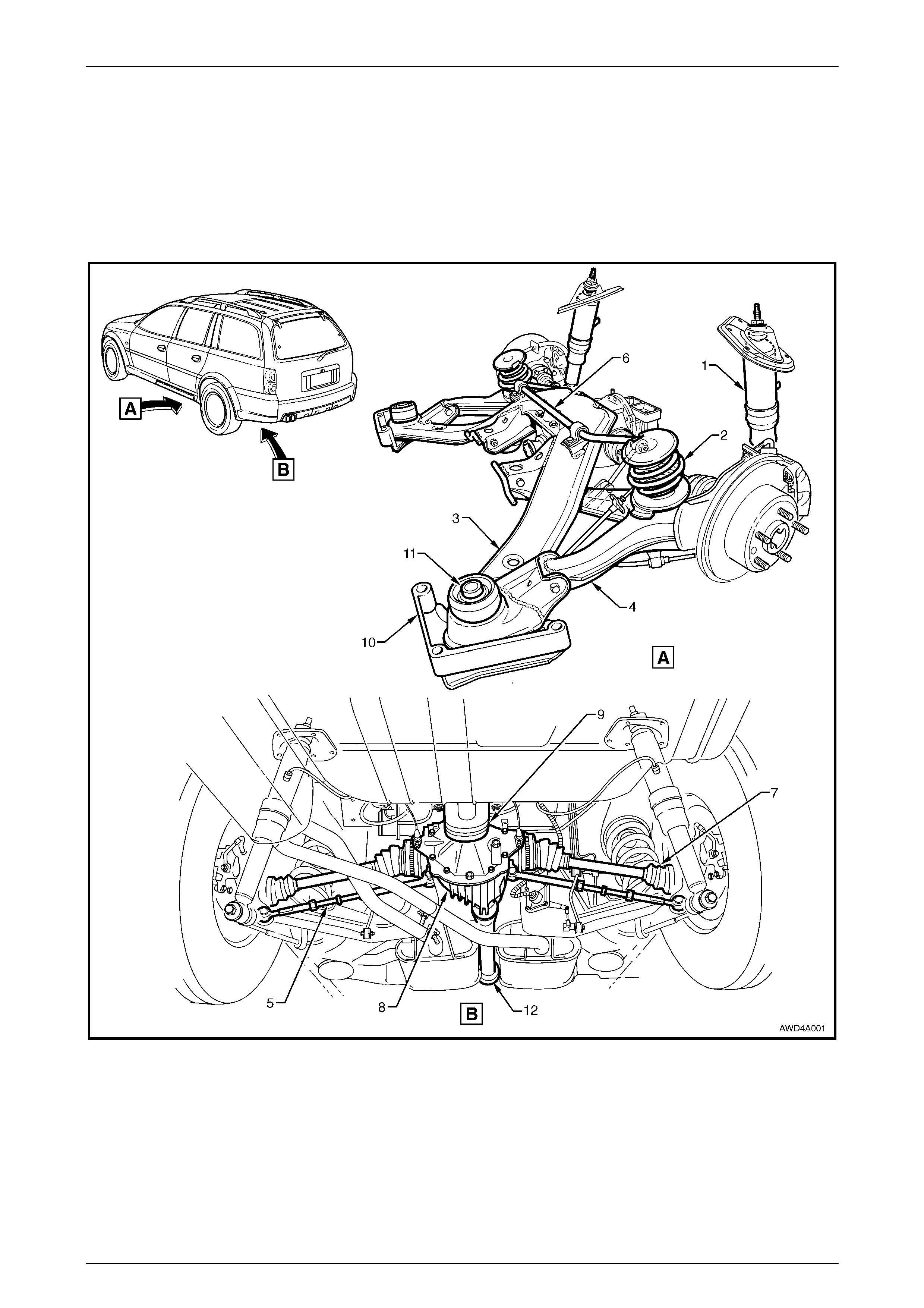
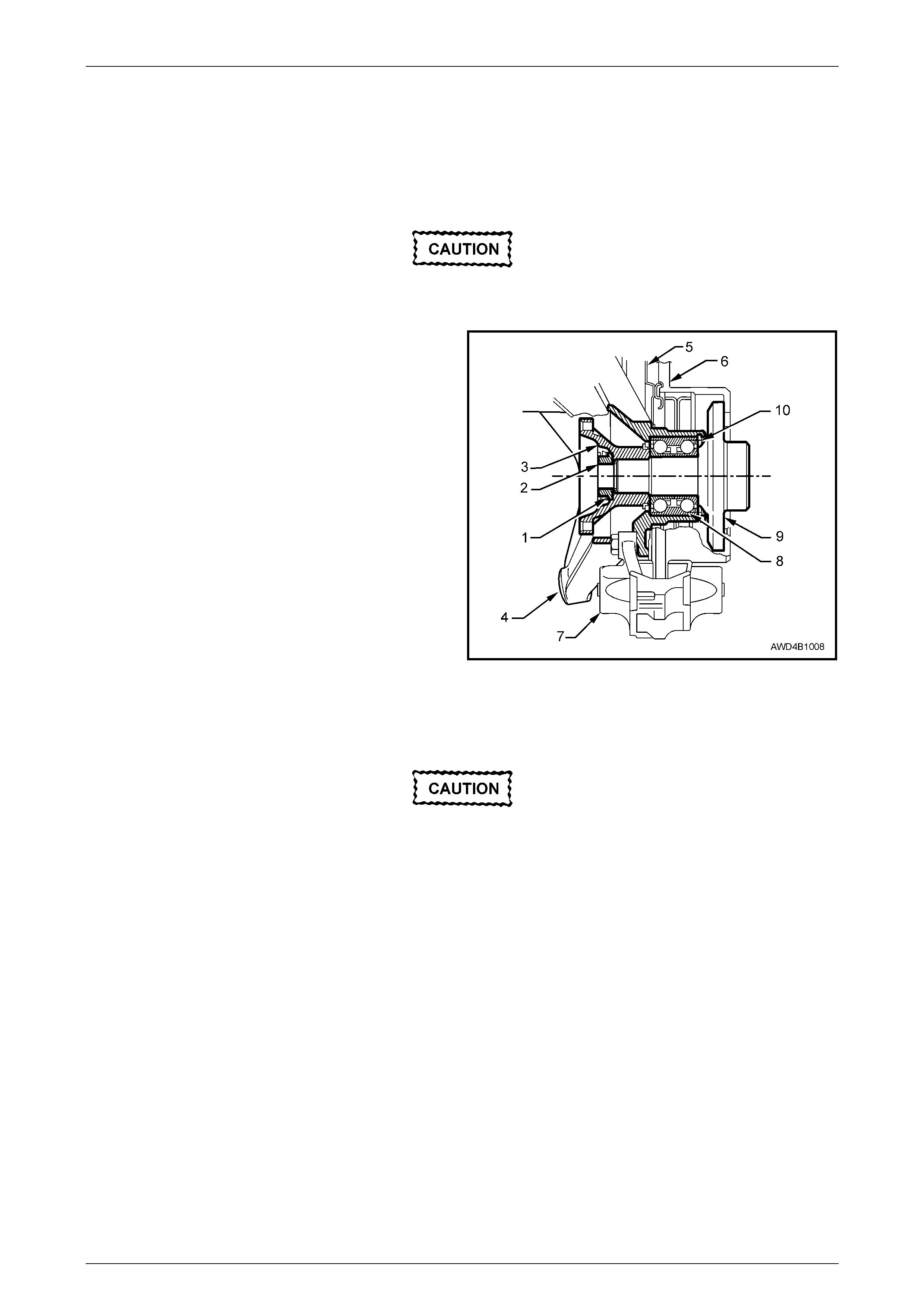
Figure 4A – 1
Legend
1 Rear Shock Absorber
2 Rear Spring
3 Rear Suspension Crossmember Assembly
4 Rear Suspension Cont rol Arm Assembly
5 Additional Control Arm Assembly
6 Stabiliser Bar
7 Driveshaft (2 Places)
8 Rear Final Drive Assembly
9 Rear Suspension Crossmember Rear Mount
10 Rear Suspension Crossmember Front Mounting Brace
11 Front Mount Snubber Bush
12 Rear Propeller Shaft Assembly

Rear Suspension Page 4A-3
Page 4A-3
• The rear trailing arms have also been redesigned and this results in a revised procedure being required when
replacing the outer rear wheel driveshaft, rear brake dust shield or the rear wheel bearing.
• The LX8, MY 2004 AWD Wagon model features an automatic level ride suspension as standard equipment, that is
similar to that available for the MY 2004 WK Series range of vehicles. For information relating to the level ride
suspension, refer to Section 4A Rear Suspension, in the MY 2004 WK Series Service Inform ation.
For all service operations not in cluded in this Section, refer to Section 4A Rear Suspension, in the MY 2004 WK Series
or the MY 2003 VY and V2 Series Service Information.

Rear Suspension Page 4A-4
Page 4A-4
2 Service Operations
ATTENTION
All suspension fasteners are important attaching parts as they affect the performance of vital components
and/or could result in major repair expense. Where specified in this section, fasteners MUST be replaced with
parts of the same pa rt number or a GM approved equivalent. Do not use fasteners of an inferior quality or
substitute design.
Torque values must be used as specified during reassembly to ensure proper retention of all rear suspension
components.
Throughout this section, fastener torque wrench specifications may be accompanied with the following
identification marks:
!
!!
! Fasteners must be replaced after loosening.
"
""
" Fasteners either have micro encapsulated sealant applied or incorporate a mechanical thread lock and
should only be re-used once. If in doubt, replacement is recommended.
#
##
# Vehicle must be at curb height before final tightening.
If one of these identification marks is present alongside a fastener torque wrench specification, the
recommendation regarding that fastener must be adhered to.
2.1 Service Notes And Cautions
CAUTION
Whenever any component that forms part
of the ABS – TC system is disturbed
during Service Operations, it is vital that the
complete ABS – TC system be checked,
using the procedure detailed in
Section 5B AWD ABS – TC, in the MY 2004
AWD Wagon Service Information.
NOTE
Whenever a road wheel and/or brake disc
is removed from or installed to a MY 2004
AWD Wagon vehicle, it MUST be done in
accordance with the procedure provided. Refer to
Section 10 Wheels and Tyres, in the VY and V2
Series Service Inform ation.
Rear Suspension Page 4A-5
Page 4A-5
2.2 Rear Wheel Stud
LT Section No.: 05-290
Replace
1 Raise the rear of vehicle and s upport in a safe mann er. Ref er to Section 0A General Information, in the MY 2003
VY and V2 Series Service Information, for the locati on of jacking and support points.
2 Remove the decorative wheel nut caps on the side where the wheel stud is to be replaced, then mark the
relationship of the road wheel to one of the wheel studs.
3 Loosen, then remove the road wheel attaching nuts, working in a 'star' pattern. Refer to Section 10, Wheels and
Tyres, in the MY 2003 VY and V2 Series Service Information, for detailed information. Remove the road wheel.
NOTE
Steps 2 and 3 are necessary to maintain
component relationships and to avoid brake rotor
distortion and the creation of brake shudder, after
the vehicle is placed back in service.
4 Remove the two brake caliper anchor plate to trailing arm bolts and discard, as they must be replaced on
reassembly.
The caliper is not to hang by the brake hose,
when the caliper is removed.
5 Slide the brake caliper from the brake rotor and support with tie wire, to the rear spring or other convenient point.
6 Use correction fluid (e.g. whiteout) to mark the relationship of the brake rotor to the trunnion assembly.
7 Remove the brake rotor from the trunnion.
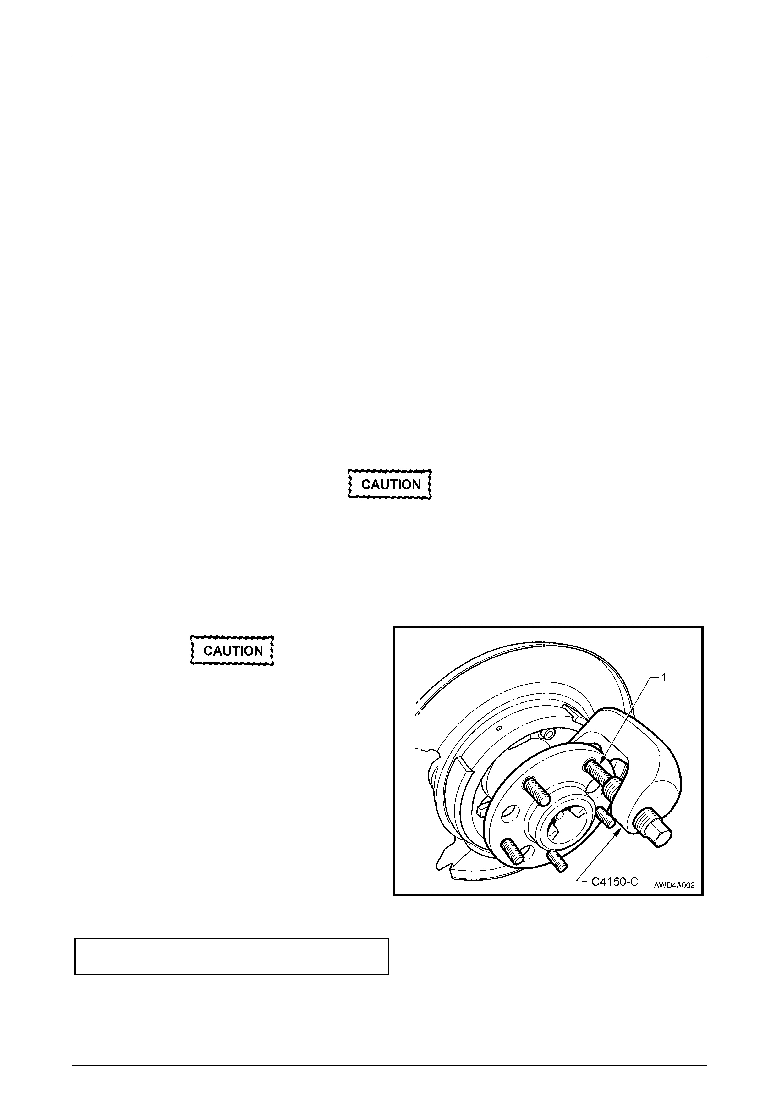
The use of a hammer and punch to remove a
wheel stud is not permitted, as distortion of
the outer rear wheel driveshaft assembly will
most likely occur. This would subsequently
result in brake shudder.
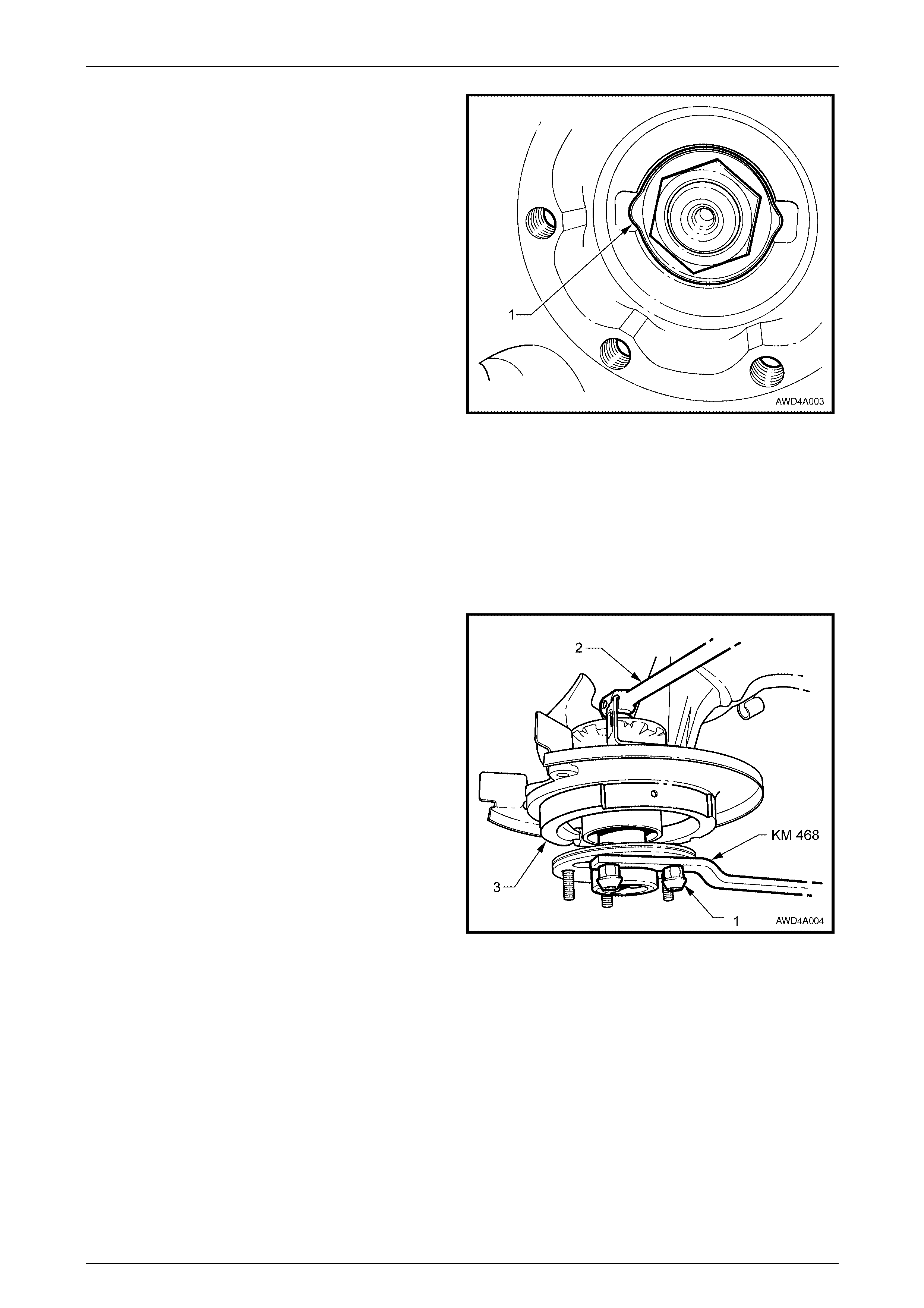
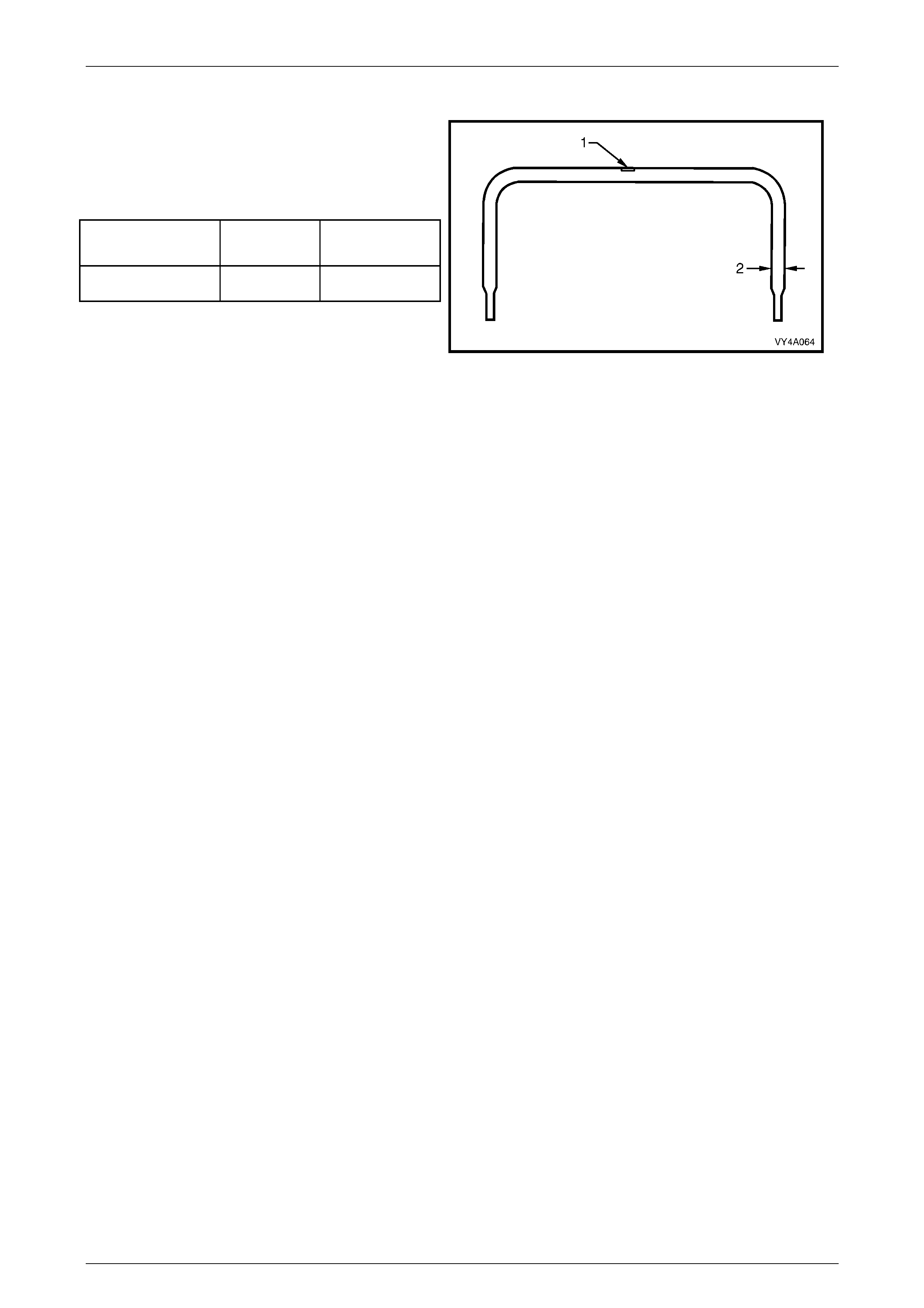
8 Use Tool No. C4150-C, to remove the wheel stud (1)
that is to be replaced.
9 Fit a new wheel stud to the outer rear wheel driveshaft
assembly, then use a flat washer and a wheel nut to
fully install.
10 Reinstall the brake rotor, aligning the marks made on
removal.
11 Reinstall the brake caliper, secure with the anchor
plate bolts and tighten to the correct torque
specification.
Brake caliper anchor plat e
bolt torque specification ........................................ 85 Nm
Figure 4A – 2
Rear Suspension Page 4A-6
Page 4A-6
12 Reinstall the road wheel, aligning the marks made before removal. Reinstall the wheel nuts but do no fully tighten
at this stage.
13 Lower the vehicle to the ground, then tighten the road wheel nuts to the co rrect torque specification. Work in a 'star'
pattern, refer to Section 10, Wheels and Tyres, in the MY 2003 VY and V2 Series Service Information.
Road wheel attaching nut
torque specific atio n ............................................125 Nm
Rear Suspension Page 4A-7
Page 4A-7
2.3 Outer Rear Wheel Driveshaft Assembly,
Brake Dust Shield and Wheel Bearing
LT Section No: 05-290
This service operation will destroy the outer
rear wheel driveshaft double row ball bearing.
Legend
1 Collar Nut Lock Pl ate
2 Collar Nut
3 Rear Wheel Driveshaft Flange
4 Rear Suspension Cont rol Arm
5 Rear Brake Dust Shiel d
6 Brake Rotor
7 Brake Caliper
8 Rear Wheel Bearing
9 Outer Rear Wheel Driveshaft
10 Rear Wheel Bearing Retaining Circlip
Figure 4A – 3
Remove
• If automatic level ride suspension is fitted
to the vehicle, there are specific
procedures relating to the system
pressure and the removal of the shock
absorber. Refer to Section 4A Rear
Suspension, in the MY 2004 WK Series
Service Information, for this information.
• During driveshaft removal and
reinstallation, the driveshaft 'free' end
MUST be supported to keep constant
velocity joint angles to a minimum.
Excessive angles and/or dropping the
'free' end will cause damage to the boot
cap and the joint itself.
1. Remove the rear suspension control arm on the side where this service operation is to be carried out. Refer to
2.2 Rear Suspension Control Arm, Section 4A Rear Suspension, in the MY 2003 VY and V3 Series Service
Information and Section 4A Rear Suspension, in the MY 2004 WK Series Service Information.
Rear Suspension Page 4A-8
Page 4A-8
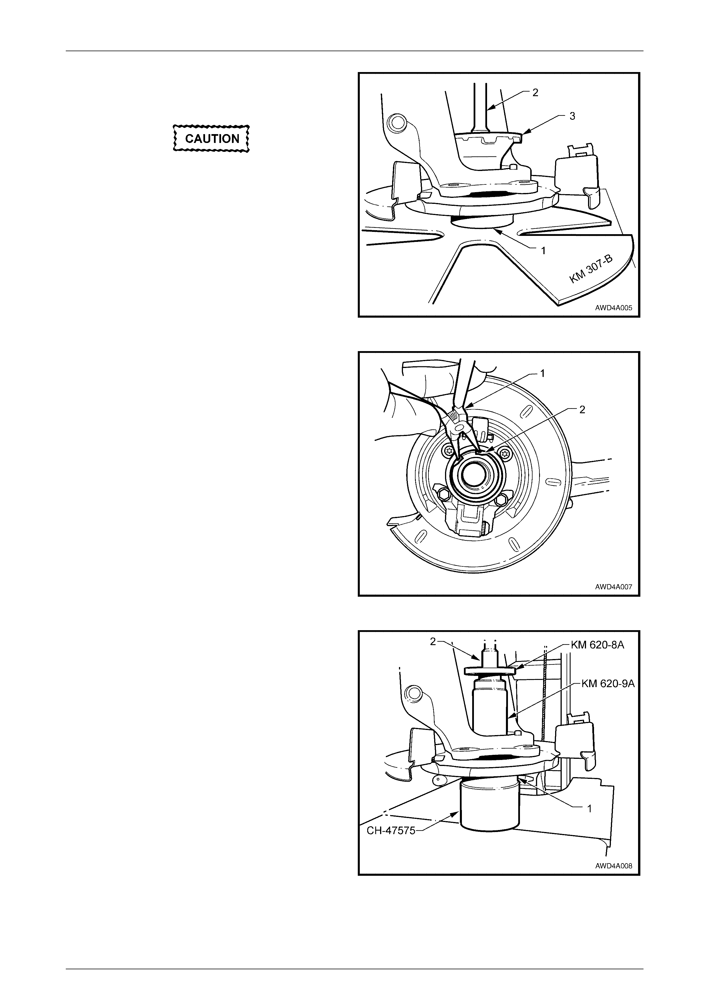
2 Distort the rear wheel driveshaft flange collar nut lock
plate (1) using a suitable size pin punch and hammer,
then remove and discard the lock plate.
Figure 4A – 4
3 If the outer rear wheel driveshaft is to be reinstalled (i.e. the bearing only is to be replaced), use correction fluid
(e.g. whiteout) to mark the relationship of the brake rotor to the driveshaft.
4 Remove the brake rotor from the outer rear wheel driveshaft.
NOTE
The brake caliper was removed during the trailing
arm removal process.
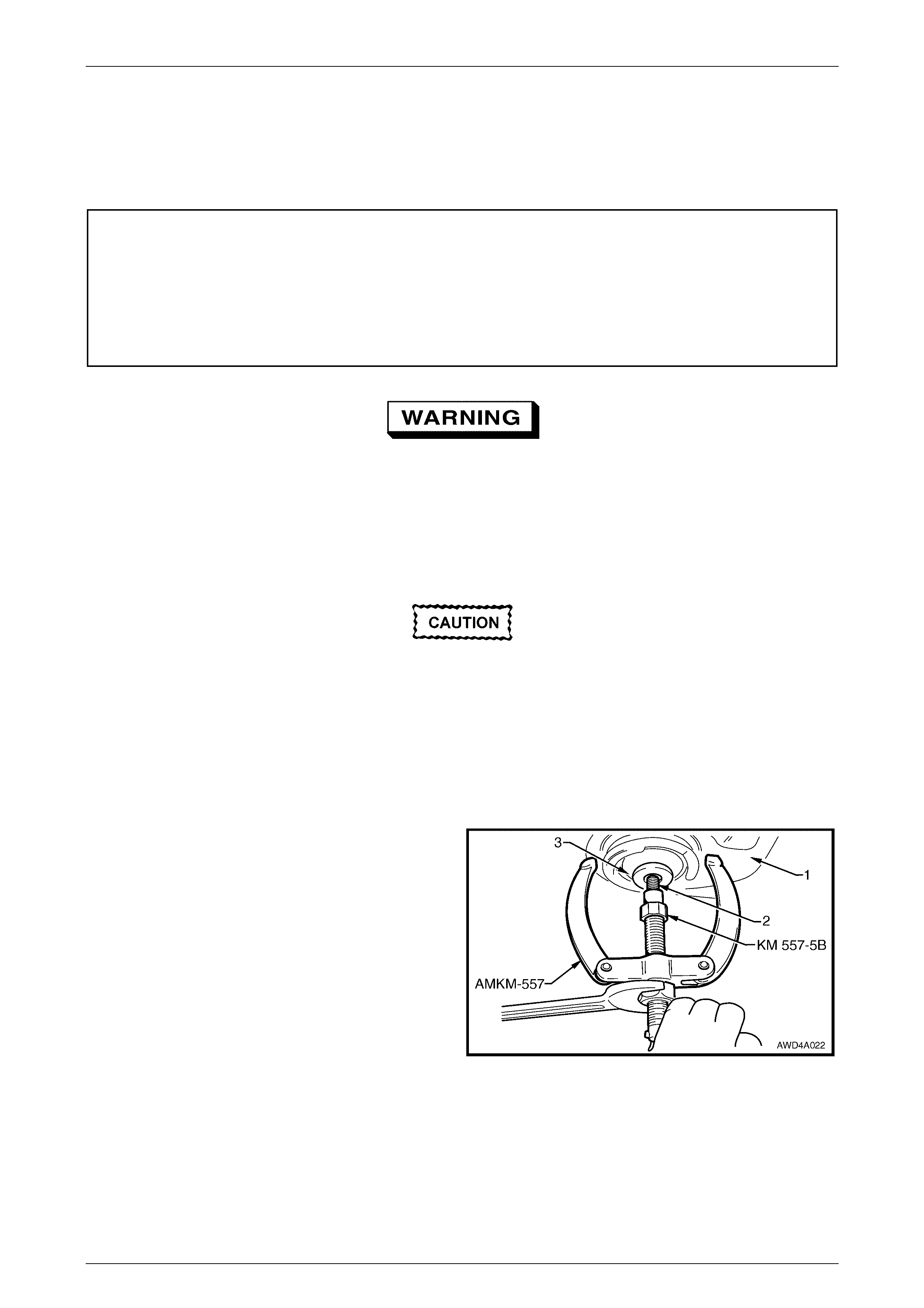
3 To support the control arm and to lift the brake backing
plate from the ground, place a block of wood under the
control arm (not visible in the view shown).
4 Install holding bar, Tool No. KM 468 to two of the
wheel studs and secure with two, reversed wheel
nuts (1).
5 Using suitab le soc ket equipm ent (2), loosen, then
remove the collar nut.
NOTE
As the tightening torque on this nut is very high,
using a suitable length of pipe over the breaker
bar, will reduce the loosening effort required.
6 Remove the park brake shoe (3) by pushing upward to
free the shoe from the top retaining clip.
Figure 4A – 5
Rear Suspension Page 4A-9
Page 4A-9
7 Use a suitable press plate such as KM 307-B or
equivalent, support the bearing hub (1) of the control
arm, in a press.
Do not allow the removed outer rear wheel
driveshaft (hidden in view shown) to strike
the floor, as damage could easily occur,
resulting in a possible unnecessary
replacement.
8 Using a suitable length of bar (2) (e.g. socket
extension), press the driveshaft (hidden from view)
from the driveshaft fl ange (3) and bearing.
NOTE
This action will separate and destroy the double
row ball race.
Figure 4A – 6
9 Using suitable circlip pliers (1), remove the bearing
retaining cir clip (2) from the control arm beari ng hub.
Figure 4A – 7
10 Fit the rear wheel bearing receiver, Tool No. CH-
47575 under the control arm bearing hub (1), indexing
the recess over the bearing hub. Position both over
press plates.
11 Assemble Tool No's KM 620-9-A and KM 620-8-A,
together with a suitable length of pipe/rod (2)
(e.g. socket extension), over the rear wheel bearing.
Press the bearing from the trai ling arm, then discard
the bearing.
Figure 4A – 8

Rear Suspension Page 4A-10
Page 4A-10
12 If the driveshaft (1) is to be re-used, then the outer half
of the bearing cone (2) will need to be removed:
a Install press plates, such as J22919-01 under
the bearing cone and tighten the press plate
bolts to grip the cone.
b Press the driveshaft from the b earing cone,
taking care not to allow the trunnion (1) to fall to
the floor.
Figure 4A – 9
13 To remove the brake dust shield (1) from the control
arm:
a Remove the top two bolts (2), using a T50 Torx
bit and suitable socket equipment.
b Use suitable socket equipment to remove the
two bolts (2) securing both the brake dust shield
(3) and the park brake actuator assembly (4) to
the control arm bearing hub.
c Remove the dust shield (3) from the control arm
bearing hub. If required, prise the park brake
actuator assembly (4) from the locating
extrusions on the dust shield.
Figure 4A – 10
If either/both rear suspension control arm bushing/s require replacement, replace the bushing/s. Refer to Rear
Suspension Control Arm Pivot Bushing, Replace, 2.2 Rear Suspension Control Arm in Section 4A Rear Suspension,
in the MY 2003 VY and V2 Series Service Information.
Reinstall
1 Ensure that the bearing bore of the rear suspension control arm is clean and free of any foreign matter or damage.
2 Clean each of the four dust cover to trailing arm threaded holes in the trailing arm, using an intermediate tap
(M10 x 2.5).
3 Coat the outside diameter of a new wheel bearing and the bore of the rear suspension control arm with a lubricant
such as Molybond HB50 (or a commercially available equivalent).
Rear Suspension Page 4A-11
Page 4A-11
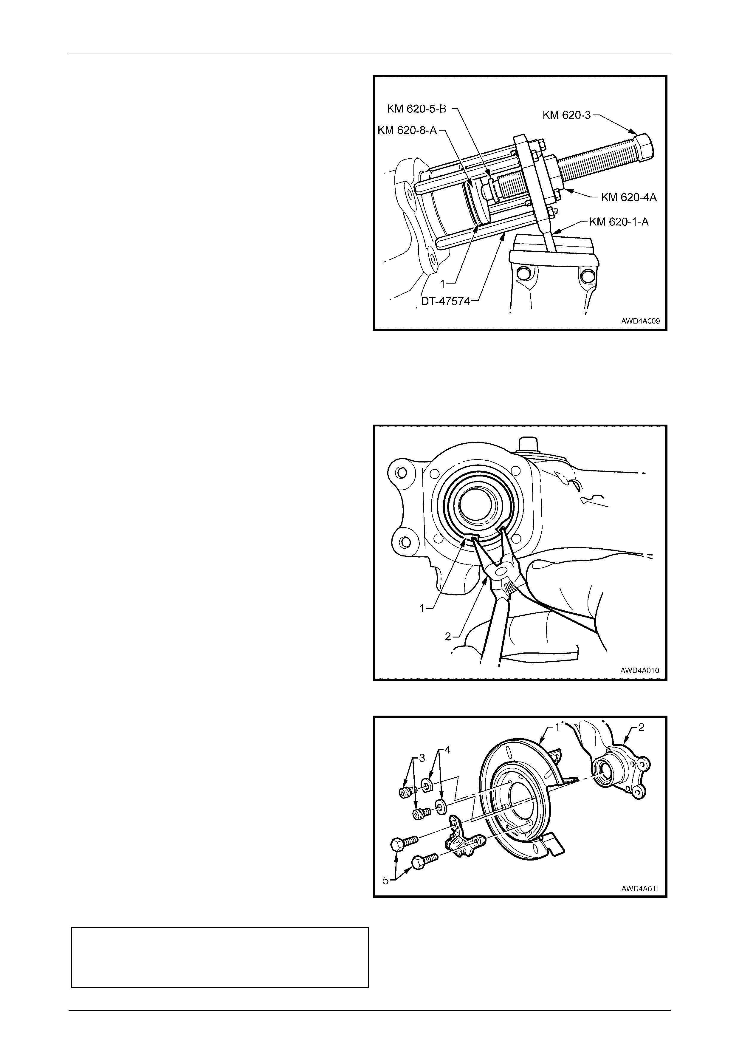
4 Insert the new bearing (1) into the bearing bore, then
assemble the installation tools:
a Install the four equal length stand-offs Tool No.
DT-47574 into the trailing arm and tighten (do
not tighten excessively).
b Insert bearing installer, Tool No. KM 620-8-
A
into
the new bearing (1)
c Install adaptor, Tool No. KM 620-4A to the
holder Tool No. KM 620-1-A, securing with the
three bolts supplied.
d Install holder Tool No. KM 620-1-A over the
stand-offs and secure with the supplied nuts.
d Lubricate the threads of forcing screw, Tool No.
KM 620-3, then thread into the adaptor, Tool No.
KM 620- 4 A, after installing the plug Tool No.
KM 620-5-B.
5 With the leg of the holding tool, KM 620-1-A held by
soft jaws in a vice, use suitable socket equipment to
rotate the forcing screw, KM 620-3, to fully install the
bearing.
Figure 4A – 11
6 Once the bearing is fully installed, remove all installation tools.
7 Reinstall the bearing retaining circlip (1), using suitable
circlip pliers (2).
Figure 4A – 12
8 Reinstall the brake shield (1) to the rear suspension
control arm (2), and secure with the original bolts ('3'
and '5').
NOTE
• The two upper Torx headed bolts (3) have
washers (4) that are installed with the cut-out
edge facing around the rear suspension
control arm hub outer surface.
• Apply Loctite 242 thread sealant (or
equivalent) to the cleaned threads of the two
longer, lower hexagon headed bolts (5),
before installation.
9 Tighten all bolt s to the correct torque sp eci fic atio n.
Rear brake shield to rear
suspension control arm
bolt torque specification Upper Bolt............75 Nm
Lower Bolt............88 Nm
Figure 4A – 13
Rear Suspension Page 4A-12
Page 4A-12
10 Reinstall the park brak e shoe (1) to the brake dust
shield. Refer to Section 5A Service and Park Braking
System, in the MY 2003 VY and V2 Series Service
Information.
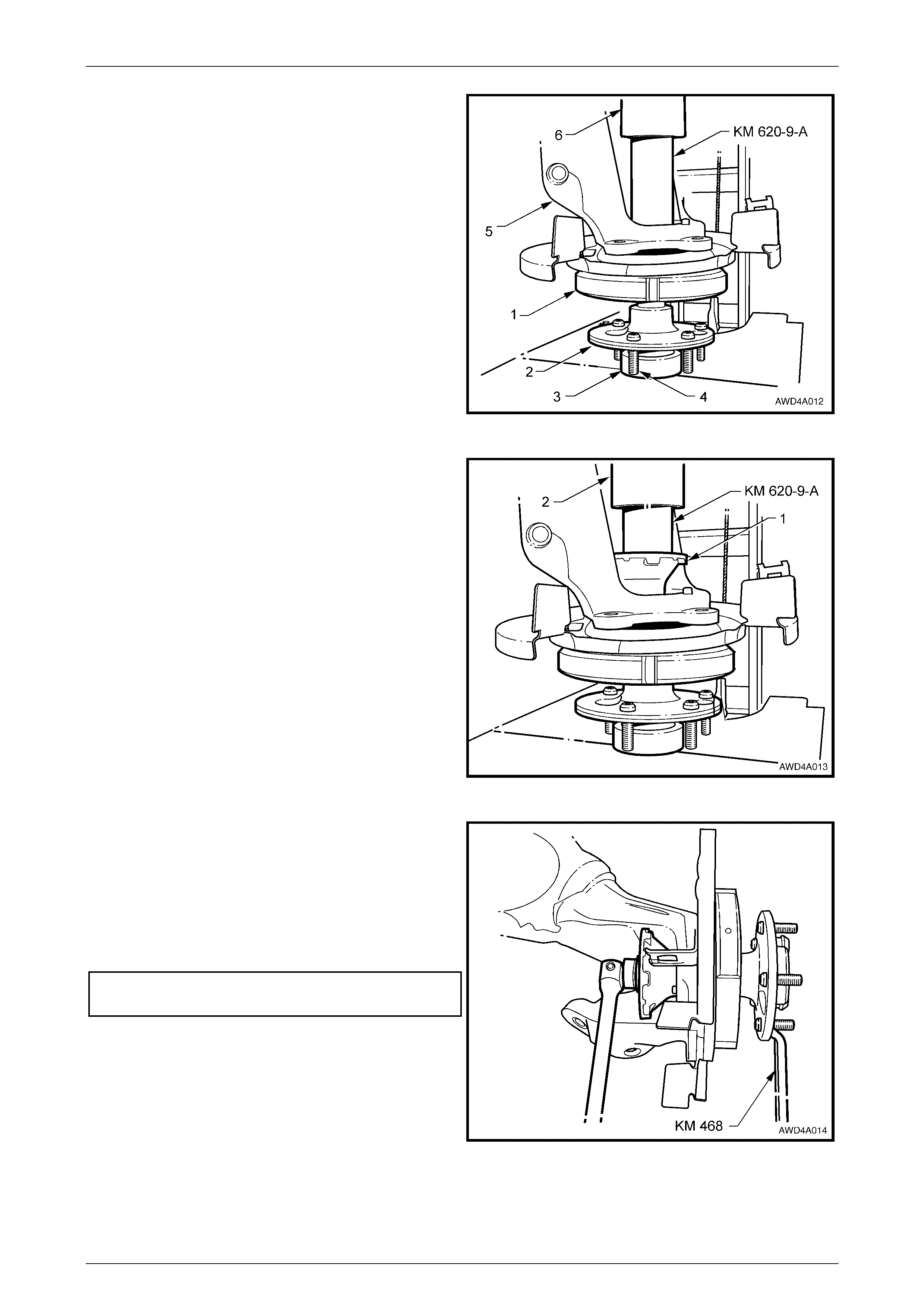
11 Position the outer rear wheel trunnion (2) with the
centre hub section resting on a suitable support (3)
and press plates, checking to make sure that the outer
rear wheel driveshaft wheel studs (4) do not contact
press plates.
12 Position the rear suspension control arm (5) and wheel
bearing onto the outer rear wheel driveshaft.
13 With an assistant supporting the rear suspension
control arm assembly (5) in this position, use installer
KM 620-9-A and steel pipe (6) of suitable length and
diameter, to press wheel bearing onto the outer rear
wheel driveshaft.
Figure 4A – 14
14 Lubricate the outer rear wheel driveshaft splines and
threads with a suitable lubricant such as Molybond
HB50 (or equivalent), then engage the rear wheel
driveshaft flange splines with those on the outer rear
wheel driveshaft.
15 With the outer rear wheel drives haft setup as in Steps
10 and 11, press the rear wheel driveshaft flange (1)
onto the outer rear wheel driveshaft, using installer
KM620-9-A and a suitable steel pipe (2)
Figure 4A – 15
16 To support the control arm and to lift the brake backing
plate from the ground, place a block of wood under the
control arm (not visible in the view shown).
17 Install holding bar, Tool No. KM 468 to two of the
wheel studs and secure with two, reversed wheel nuts.
18 Install a new flange collar nut and tighten to the correct
torque specif ication.
! Collar nut to rear driveshaft
flange torque specification..................................300 Nm
Figure 4A – 16

Rear Suspension Page 4A-13
Page 4A-13
19 Fit a new lock plate over the collar nut, then install
using a suitable diameter socket (1 1/4") (1), 150 mm
socket extension (2) and hammer (3), a new.
20 Use a suitable sized pin punch and hammer to index
the lock plate into the slots on each side of the
driveshaft flange. Refer to Figure 4A-4.
Figure 4A – 17
Rear Suspension Page 4A-14
Page 4A-14
2.4 Rear Suspension Crossmember
LT Section No. – 07-150
ATTENTION
The following fasteners MUST be replaced when performing these operations:
!
!!
! Rear suspension crossmember rear mount to under body attaching bolt.
!
!!
! Rear suspension crossmember front mounting bolt.
!
!!
! Differential carrier to rear suspension crossmember attaching bolts.
The following fasteners have either micro encapsulation or incorporate a mechanical thread lock and should
only be used once. If in doubt, replacement is recommended when performing this operation:
" Rear suspension crossmember front mounting brace to under body attaching bolts.
" Additional control arm inner shaft attaching nut.
" Rear suspension control arm to rear suspension crossmember attaching nut.
The following fasteners MUST be at curb height before final tightening:
•
••
• Rear suspension control arm to rear suspension crossmember attaching nut.
•
••
• Shock absorber lower mounting bolt.
Whenever any component that forms part of
the ABS – TC is disturbed during Service
Operations, it is vital that the complete ABS
system be checked, using the detailed
procedure. Refer to Section 5B AW D ABS – TC
in the MY 2004 AWD Wagon Service
Information.
Before disturbing the rear suspension
crossmember mounting bolts, an alignment
procedure is required on installation and a
special tool is required for this purpose. If this
tool is not available, then the crossmember
cannot be correctly aligned and steering
and/or handling abnormalities will result.
Remove
Apart from the items mentioned here, refer to 2.5 Rear Suspension Crossmember, R emove, in Section 4A Rear
Suspension, in the MY 2003 VY and V2 Series Service Information:
1 For removal of the exhaust system necessary for this operation, refer to Section 8B, Exhaust System, in the MY
2004 AWD Wagon Service Information for details relating to the removal and installation of the exhaust
components (including heat shields).
2 To remove the rear propeller shaft assembly, refer to Section 4C1 Rear Propeller Shaft, in the MY 2004 AWD
Wagon Service Information.
3 When removing the rear mount to underbody bolts, a spacer is located betwe en the mount and the underbody
surface.
4 For those MY 2004 AWD Wagon models fitted with the automatic level ride suspension, there are specific
procedures relating to the system air pressure and the treatment of the rear shock absorbers. For these
procedures, refer to the noted operations in Section 4A Rear Suspension, in the MY 2004 WK Series Service
Information:
3.4 Relieving System Air Pressure
3.7 Level Ride Shock Absorber
Rear Suspension Page 4A-15
Page 4A-15
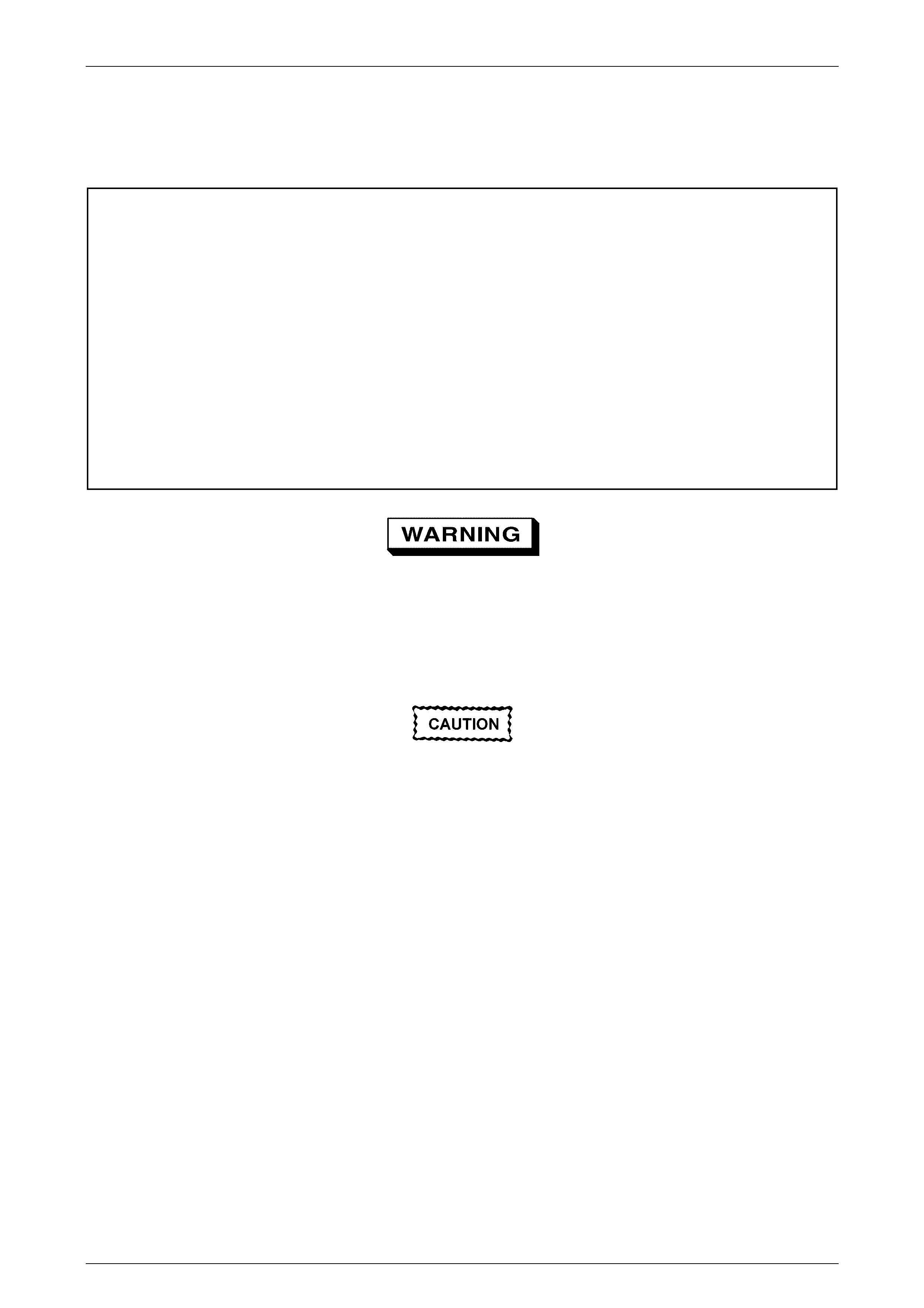
5 When the crossmem ber is lowered, che ck that each
snubber bush (4) is mounted on top of the rear
suspension crossmember front mount and is in a
serviceable condition.
6 As shown, the physical shape of the rear
crossmember front mounts and the mounting brace
spacers (1) are unique to this vehicle.
Legend
1 Mounting brace spacer.
2 Front mounting to underbody bolt.
3 Mounting brac e bol t (3 places ).
4 Snubber Bush
Figure 4A – 18
Reinstall
1 If the rear suspension crossmember has been replaced and the vehicle is fitted with the automatic level ride
suspension, then the compressor mounting holes must be drilled, in accord with specific dimensions. Refer to
3.5 Compressor Assembly, Reinstall, in Section 4A Rear Suspension, in the MY 2004 WK Series Service
Information, for details.
2 Again, if the vehicle is fitted with the autom atic level ride suspension, then the vehicle is not to be lowered to
the ground before the system is pressurised and tested for air leaks. For this information, refer to Section 4A
Rear Suspension, in the MY 2004 WK Series Service Information.
3 The remainder of the reinstallation process of the rear suspension crossmember is as detailed. Refer to
2.5 Rear Suspension Crossmember, Reinstall, in Section 4A Rear Suspension, in the MY 2003 VY and
V2 Series Service Information.
Rear Suspension Page 4A-16
Page 4A-16
2.5 Rear Suspension Crossmember Front
Mount Bushing
LT Section No. – 07-150A
ATTENTION
The following fasteners MUST be replaced when performing these operations:
!
!!
! Rear suspension crossmember front mounting bolt.
The following fasteners have either micro encapsulation or incorporate a mechanical thread lock and should
only be used once. If in doubt, replacement is recommended when performing this operation:
" Rear suspension crossmember front mounting brace to under body attaching bolts.
Whenever any component that forms part of
the ABS – TC is disturbed during Service
Operations, it is vital that the complete ABS
system be checked, using the detailed
procedure. Refer to Section 5 B AW D ABS –T C ,
in the MY 2004 AWD Wagon Service
Information.
Before disturbing the rear suspension
crossmember mounting bolts, an alignment
procedure is required on installation and a
special tool is required for this purpose. If this
tool is not available, then the crossmember
cannot be correctly aligned and steering
and/or handling abnormalities will result.
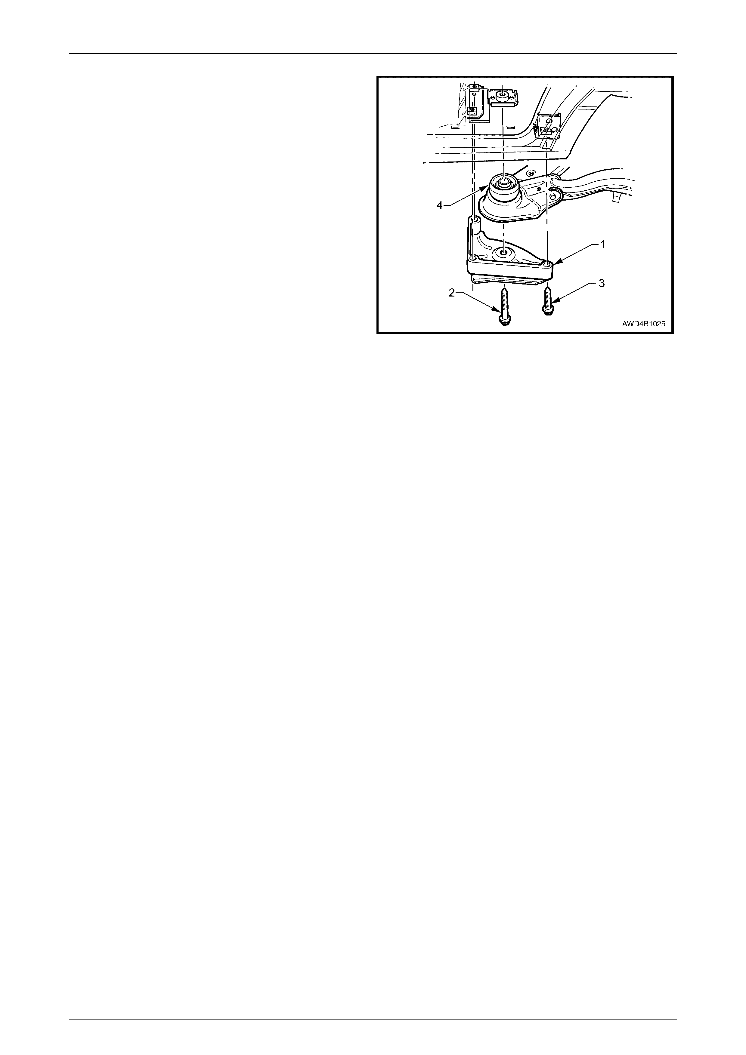
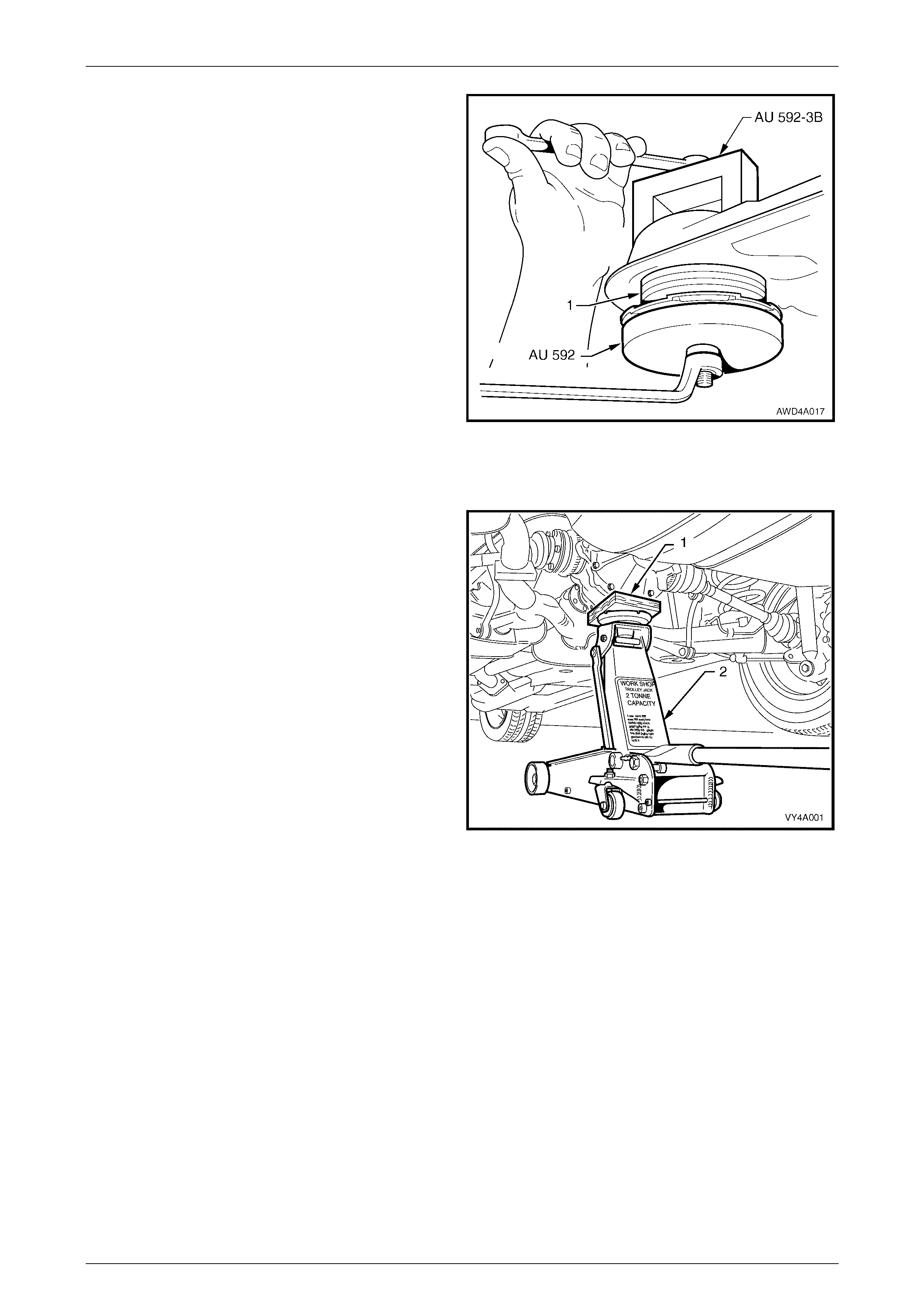
Off-Car Replacement
1 With the rear suspension crossmember (1) removed
from the vehicle and the snubber bush removed, insert
the bolt (2) (part of bush installer, Tool No. AU-592)
through the bushing (3) from above.
NOTE
For information regarding the removal
and installation procedure for the rear
suspension crossmember assembly, refer to
2.4 Rear Suspension Crossmember, in this
Section.
2 Screw bolt (2) (a part of AU 592) into the adaptor KM
557-5B) that was previously screwed into puller, Tool
No. AMKM-557.
3 Tighten the forcing nut while holding the threaded
shaft of Tool No. AMKM-557 until the bushing is
removed from the cross memb er.
4 Remove the bolt from the puller and adaptor assembly
and discard the bush.
Figure 4A – 19
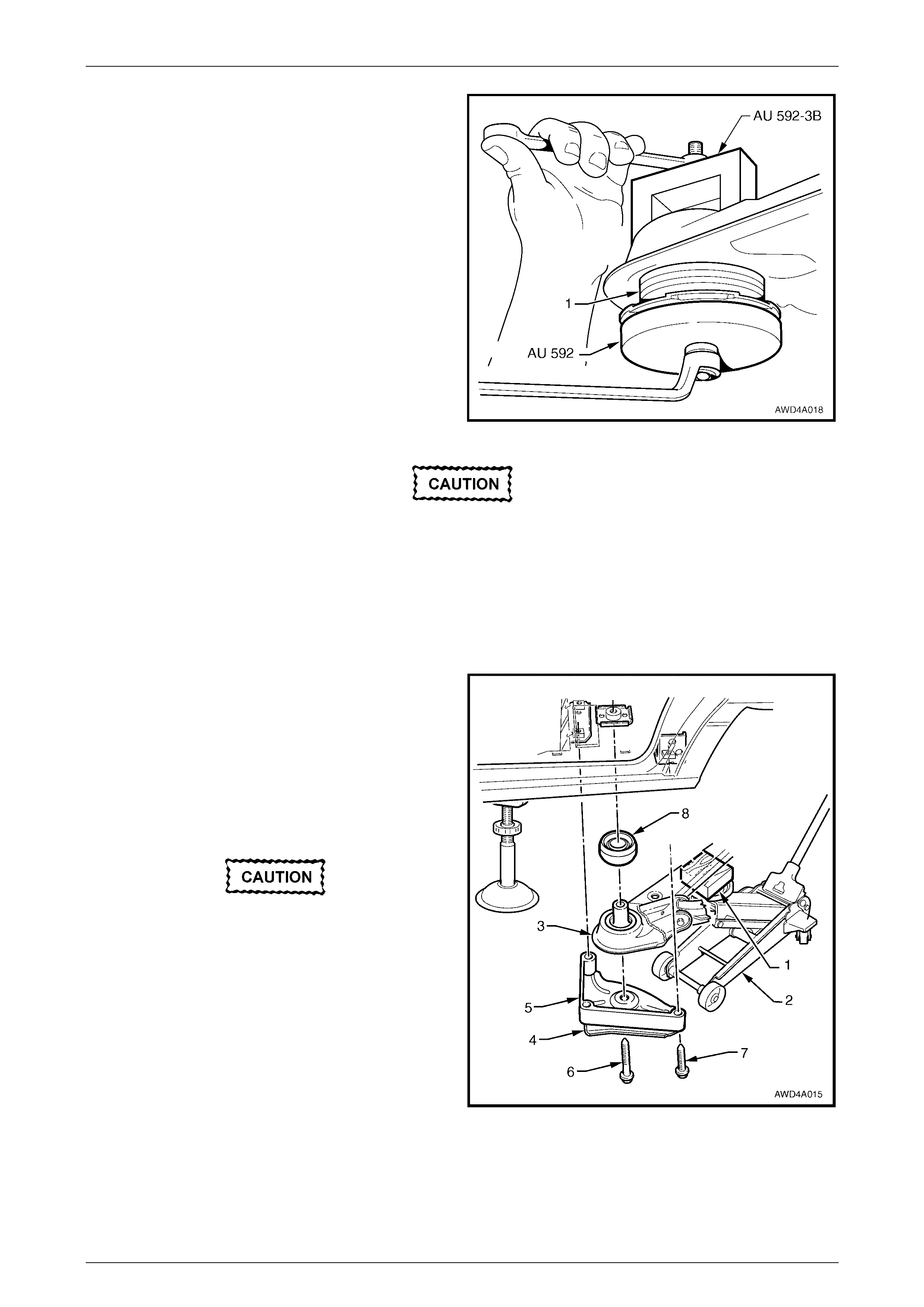
Rear Suspension Page 4A-17
Page 4A-17
5 Apply a soap solution to the outside surface of the new
hydraulic bushing.
6 Assemble Tool No. AU 592 as shown, with support
block, AU 592-3B at the top of the crossmember, as
shown.
7 While holding the bolt head, tighten the nut to push the
bushing into the crossmember until fully installed.
8 Remove the installation tools.
Figure 4A – 20
On-Car Replacement
1 Using a floor jack (2) with a suitable wood block (1)
mounted on top of the floor jack to support and prote ct
the underside of the rear final drive housing, raise the
rear of the vehicle.
2 Position safety stands to support the vehicle weight at
both the LH side and RH side under body rear jacking
points. Refer to Section 0A General Information in the
MY 2003 VY and V2 Series Service Inform ation, for
the detailed information regarding the location of the
vehicle support points.
Figure 4A – 21
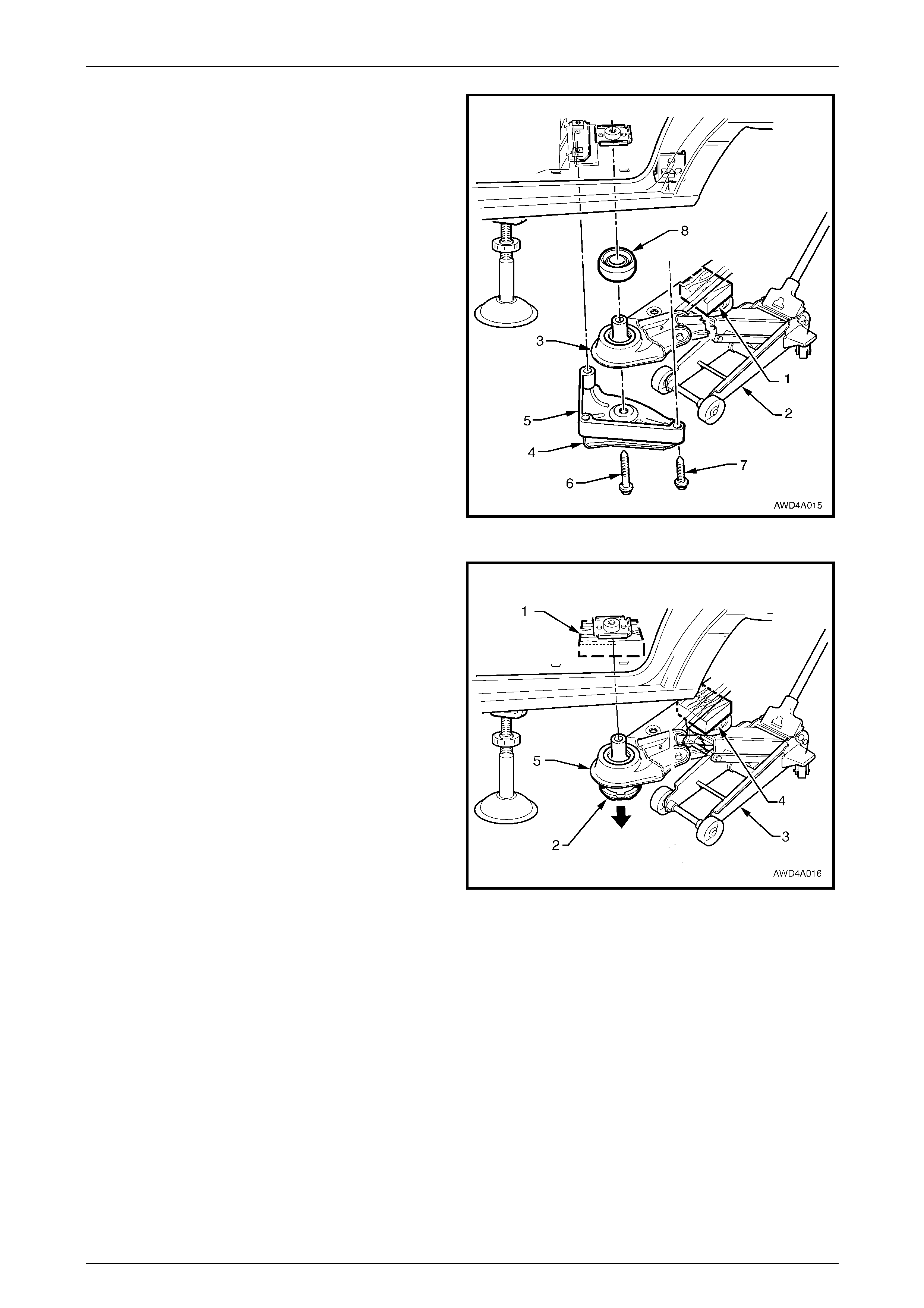
Rear Suspension Page 4A-18
Page 4A-18
3 Position a floor jack (2) with a suitable block of wood
(1) mounted on top of the jack lifting pad to support
and protect the rear suspension crossmember
assembly (3) during the following procedure.
4 Take up the weight of the crossmember by raising the
floor jack to make contact with the crossmember,
nearest to the side on which the bushing is to be
replaced.
5 Loosen then remove the crossmember mount to
mounting brac e, central bolt (6) and discard.
6 Remove the brace (4) and brace spacer (5) to vehicle
underbody attaching bolts (7) (3 places). Set the brace
and spacer to one side.
7 Lower the floor jack slightly to allow clearance
between the crossmember and the vehicle underbody.
8 Remove the snubber bush (8).
Figure 4A – 22
9 Place a suitable block of wood (1), approximately
100 mm x 100 and 50 mm thick, between the bushing
(2) to be removed and the vehicle underbody.
10 With a suitable block of wood (4) mounted on top of
the jack lifting pad, raise the floor jack (3) slowly, lifting
the crossmember (5), until the bush 'stem' contacts the
wooden block (1).
11 Increase the pressure applied by the floor jack,
gradually pressing the bushing downward and free of
the crossmember. The vehicle weight and the upward
movement of the jack will apply enough force in a
downward direction to remove the bush.
12 Remove and discard the bushing.
13 Lower the floor jack once again, to allow clearance for
installation of the new bush.
Figure 4A – 23
Rear Suspension Page 4A-19
Page 4A-19
14 Apply a soap soluti on coat ing to the outer diameter
area of the new bush (1).
15 Offer the new bushing (1) up to the crossmember.
16 Assemble Tool No. AU 592 as shown, with support
block, AU 592-3B at the top of the crossmember, as
shown.
17 While holding the nut, tighten the forcing bolt, pushing
the bushing into the crossmember until fully installed.
18 Remove the installation tools.
Figure 4A – 24
Resulting from the front hydraulic bush
replacement operations, the rear
crossmember will probably have moved from
its original position.
19 To allow a new bush retaining bolt to be installed, loosen the other side, brace to underbody bolts, to allow the
crossmember bolt hole to be moved back into position.
20 With the floor jack still in position to support and protect the rear suspension crossmember assembly, raise the
cross member using the floor jack.
21 Provided the snubber bush (8) is in a serviceable
condition, reinstall the bush over the upper stem of the
crossmember bush.
22 Install the brace (4) and brace spacer (5), a NEW
crossmember front mounting to underbody bolt (6),
and the three smaller original brace attaching bolts (7),
but do not tighten the bolts at this stage.
23 If necessary, repeat steps 1 to 20 for the opposite
side.
Failure to correctly align the rear suspension
crossmember to the centreline of the vehicle
will result in steering abnormalities and or
uneven tyre wear.
24 The rear suspension crossmember MUST now be
checked for corr ect ali gnm ent to the vehicle centreline.
Using the special tool and procedure, as detailed in
Section 1A2, Body Dimensions, in the MY 2004 AWD
Wagon Service Information.
Figure 4A – 25
25 Tighten bolts (6 and 7) to the correct torque specification, using an accurate torque wrench and angle wrench, Tool
No. E7115.
Rear Suspension Page 4A-20
Page 4A-20
! Rear suspension crossmember mount
to vehicle underbody bolt
torque specific atio n ...........................................125 Nm,
then 35° turn angle
"
""
" Rear suspension crossmember brace
mounting bolt torque specification........................70 Nm
26 Using a floor jack with a suitable block of wood on the jack lifting pad to protect the centre of the rear final drive
housing, raise the rear of the vehicle.
27 Remove the safety stands, carefully lower the vehicle to the floor and remove the jack.
28 Bounce the rear suspension several times to normalise, then check and correct (as necessary), the rear wheel
al ignmen t as required. Refer to 2.7 Rear Wheel Alignment Checking, in this Section.
Rear Suspension Page 4A-21
Page 4A-21
2.6 Rear Suspension Crossmember Rear
Mount
LT Section No. – 05-290
ATTENTION
The following fasteners MUST be replaced when performing these operations:
!
!!
! Rear suspension crossmember rear mount to under body attaching bolts.
!
!!
! Rear suspension crossmember rear mount to rear suspension differential assembly rear cover attaching
bolts.
Whenever any component that forms part of
the ABS – TC is disturbed during Service
Operations, it is vital that the complete ABS
system be checked, using the detailed
procedure. Refer to Section 5 B AW D ABS –T C ,
in the MY 2004 AWD Wagon Service
Information.
Before disturbing the rear suspension
crossmember mounting bolts, an alignment
procedure is required on installation and a
special tool is required for this purpose. If this
tool is not available, then the crossmember
cannot be correctly aligned and steering
and/or handling abnormalities will result.
Replace
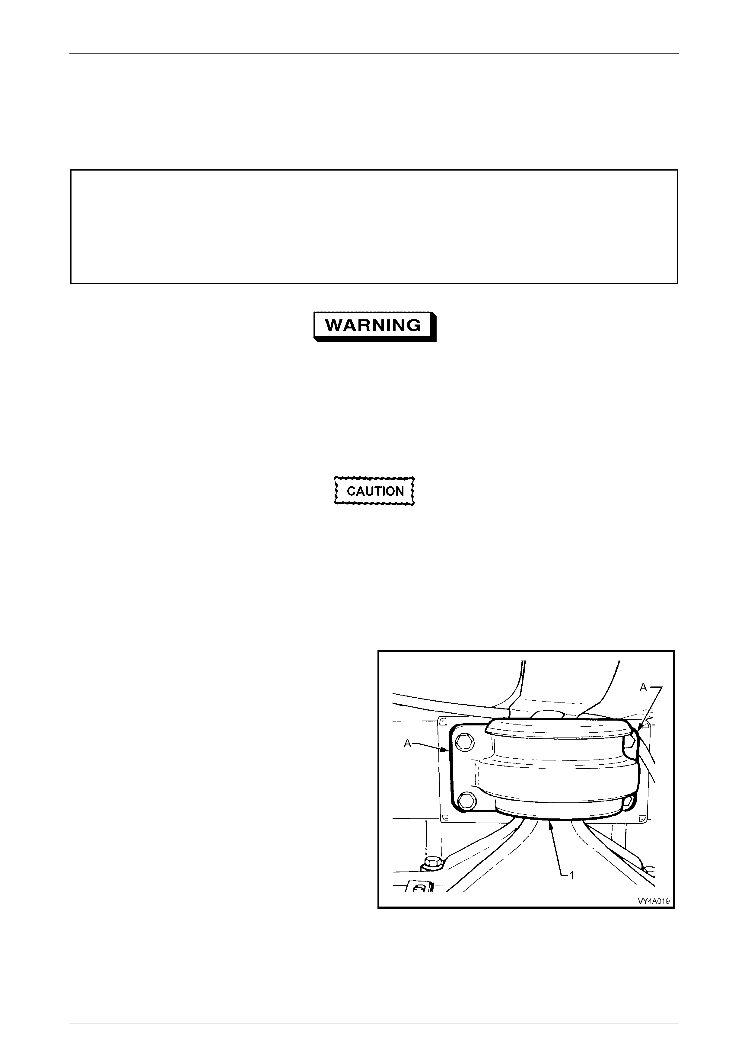
1 Using a scriber, mark the rear mount (1) to the vehicle
under body location (A). This will assist with the rear
suspension crossmember alignment on installation.
2 Support the weight of the differential carrier with a floor
jack that has a block of wood on the lifting pad to
protect the final drive housing.
Figure 4A – 26
Rear Suspension Page 4A-22
Page 4A-22
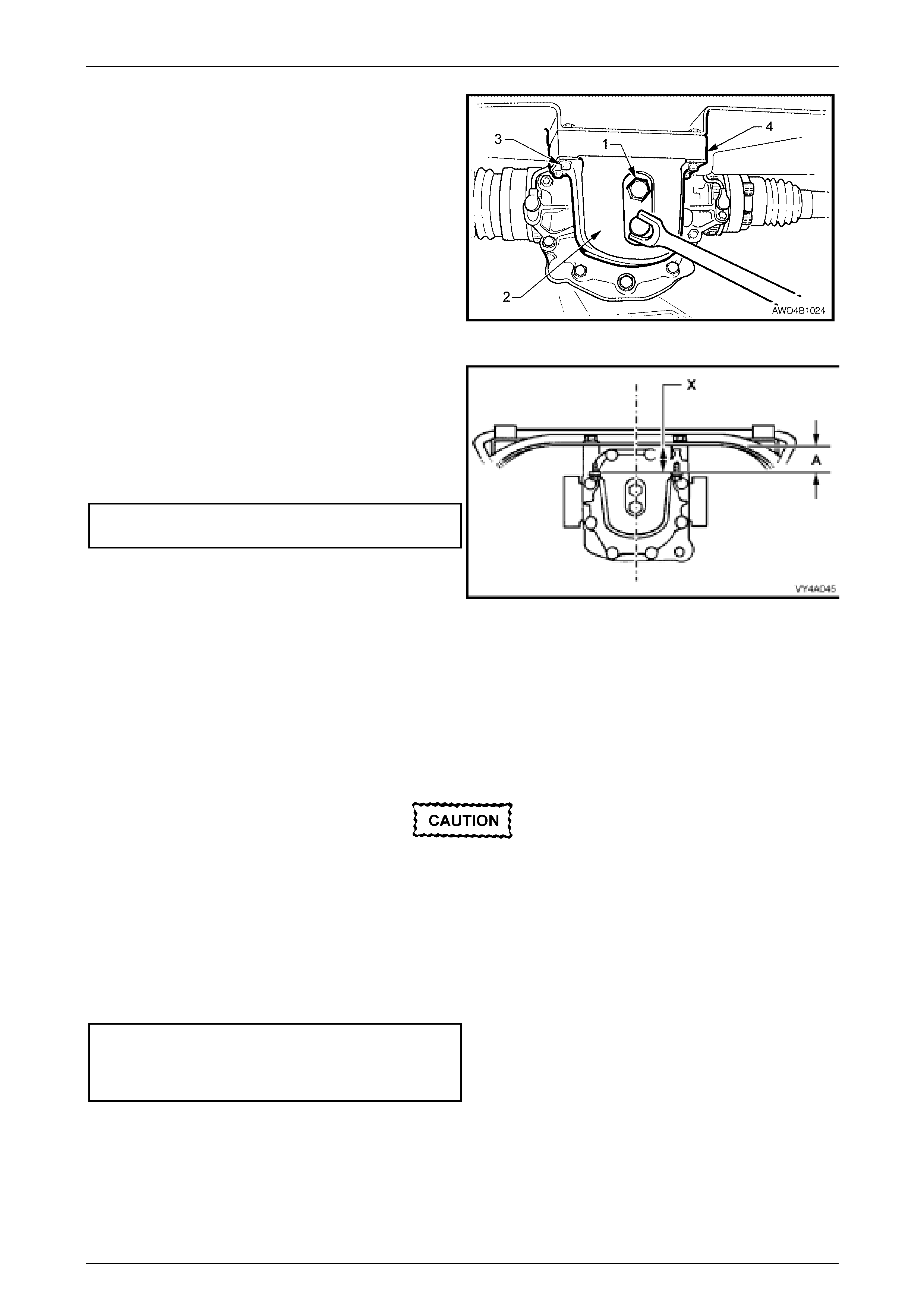
3 Remove the rear mount (2) to vehicle underbody
attaching bolts (3), then discard the removed bolts.
4 Remove and discard the rear mount to differential
carrier attaching bolts (1), lower the floor jack slightly,
then remove th e rear mount (2) and spacer block (4).
Figure 4A – 27
5 Install the rear mount and new attaching bolts to final
drive assembly rear cover.
6 While tightening the mount to final drive cover
attaching bolts to the correct torque specification,
ensure that the mount does not twist, as the mount to
vehicle underbody mating surface should be parallel to
within 1 mm (‘X’) of the rear suspension crossmember.
! Rear mount to rear final drive
rear cover bolt torque spec ification.......................95 Nm
NOTE
Use a spirit level on the rear mount to underbody
surface and the top surface of the crossmember
to ensure that both surfaces are parallel.
Dimension ‘A’ is to be 56.7 mm, including the
sp ace r block.
Figure 4A – 28
7 Raise the differential carrier and rear suspension crossmember assembly until the rear mount contacts vehicle
underbody.
8 Align the mount with the marks made on the underbody during disassembly and install new attaching bolts but do
not tighten at this stage.
Failure to correctly align the rear suspension
crossmember to the centreline of the vehicle
will result in steering abnormalities and
uneven tyre wear!
9 The rear suspension crossmember MUST now be aligned to the vehicle centreline, using the special tool and
procedure as detailed in Section 1A2 Body Dimensions in the MY 2004 AWD Wagon Service Information.
10 Tighten the rear suspension crossmember rear mount to underbody bolts to the correct torque specification, using
an accurate torque wrench and the angle wrench Tool No. E7115.
! Rear suspension crossmember
rear mount to vehicle underbody
bolt torque specification ........................................ 35 Nm
then 60° turn angle
11 Remove the safety stands and lower the vehicle.

Rear Suspension Page 4A-23
Page 4A-23
2.7 Rear Wheel Alignment Checking
LT Section No. – 07-150A
ATTENTION
The following fasteners MUST be replaced when performing these operations:
!
!!
! Rear suspension crossmember front bushing, mounting bolt.
!
!!
! Rear suspension crossmember mount to under body attaching bolt.
The following fasteners have either micro encapsulation or incorporate a mechanical thread lock and should
only be used once. If in doubt, replacement is recommended when performing this operation:
"
""
" Rear suspension control arm to rear suspension crossmember attaching nut.
The following fasteners MUST be at curb height before final tightening:
•
••
• Rear suspension control arm to rear suspension crossmember attaching nut
General Informat io n
The following conditions must be checked to ensure accurate measurement of rear wheel alignment.
1 Tread on rear tyres must be uniform and in a roadworthy condition.
2 All tyre pressures must be equal and to the correct pressure. Refer to the tyre placard on the vehicle for correct tyre
pressures.
3 Wheel rim flange lateral run-out should be checked and to specification, refer to Section 10 Wheels and Tyres, in
the MY 2004 AWD W agon Service Information.
4 The vehicle must be at curb height, i.e. vehicle ready to drive with all fluids at recommended levels, fuel tank full,
without driver, passengers or luggage.
5 Stabilise vehicle springs by rolling back and forth approximately 1 metre in each direction and bouncing the rear of
vehicle several times. This step is very important, particularly if the vehicle was raised before checking. In that
instance, the camber angle measured will be incorrect, because the rear suspension control arms will not have
resumed their normal po sition.
NOTE
Camber is not adjustable. If there is any deviation
from specification, the condition and alignment of
the crossmember, rear suspension control arms
and bushings should be checked.
NOTE
When checking wheel toe, if one side has
excessive toe-in and the opposite side has
excessive toe-out, this may be due to:
• The rear suspension control arm attaching
nuts being tightened when the vehicle was not
at curb height.
• The rear suspension crossmember not
correctly aligned to the vehicle centreline.
Alignment of the rear suspension
crossmember requires the use of a special
tool. Attempting to align the rear suspension
crossmember without it will not prove to be
successful.
Rear Suspension Page 4A-24
Page 4A-24
6 To correct such a condition, check the rear suspension crossmember alignment. Refer to Section 1A2, Body
Dimensions in the MY 2004 AW D Wagon Service Information. Following the alignment procedure, tighten
fastenings to the correct torque specifications, using an accurate torque wrench and the angle wrench, Tool No.
E7115.
! Rear suspension crossmember
front mounting bolt
torque specification ................................... 125 Nm, then
35° turn angle
! Rear crossmember rear mount
to underbody bolt torque specification......... 35 Nm, then
60° turn angle
$ • Rear suspension control arm
to rear suspension cros sm em ber
nut torque specification ......................................100 Nm
Rear Wheel Toe Adjust ment
LT Section No. – 07-150A
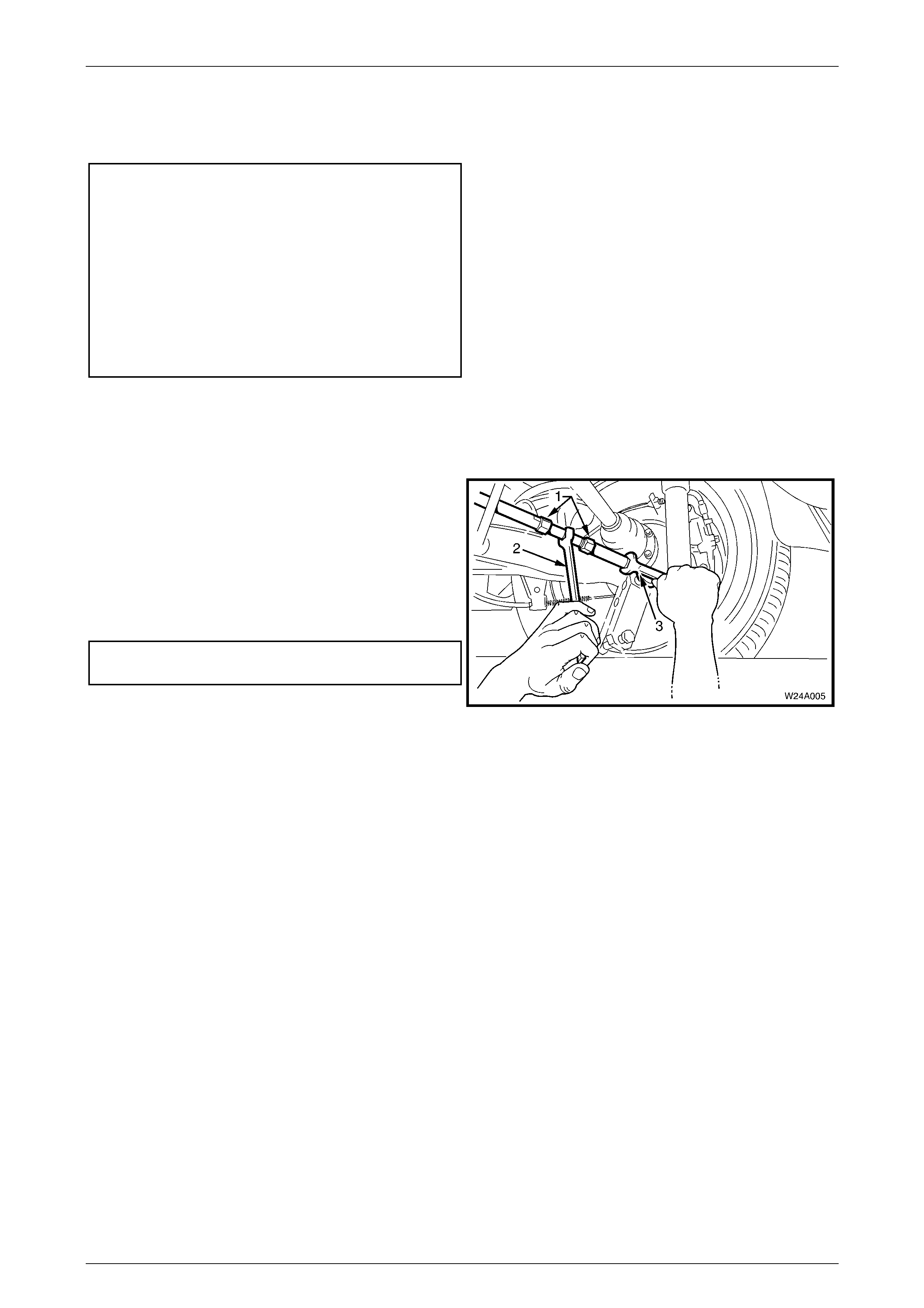
The rear suspension toe setting is adjustable by varying the
length of the additional control arm. To adjust toe setting:
1 Loosen the two lock nuts (1).
2 Using a suitable set spanner (2), rotate the centre
adjusting shaft.
3 Tighten the two lock nuts to the correct torque
specification.
Additional control arm adjusting shaft
lock nut torque specification.................................50 Nm
NOTE
• The inner additional control arm shaft, the
inner lock nut and the corresponding end of
the adjuster have left-hand threads.
• Increasing the additional control arm length
will increase rear wheel toe in and vice versa.
• The tie rod end may be over extended if
allowed to move during the tightening of the
lock nuts, causing damage to ball joint
internals. During the toe adjustment
procedure, use a suitable spanner (3) on the
hexagonal crimped section near the tie rod
end to prevent misalignment.
Figure 4A – 29

Rear Suspension Page 4A-25
Page 4A-25
3 Diagnosis
For diagnostic procedures relating to the standard rear suspension, refer to 3 Diagnosis, in th e MY 2003 VY and V2
Series Service Information and for those AWD Wagon models fitted with automatic level ride suspensions, refer to
5 Diagnosis – Automatic Level Ride Suspension in the MY 2004 WK Series Service Information.
Rear Suspension Page 4A-26
Page 4A-26
4 Specifications
Rear Suspension Service Al i gnment Dat a
SUSPENSION
CONFIGURATION REAR TRACK
(mm) REAR WHEEL CAMBER
(VARIATION SIDE TO SIDE) TOE DEGREES PER WHEEL
(VARIATION SIDE TO SIDE)
Wagon FE1 1623 Nominal –0° 30’
Range –1° 18’ to –0° 2' Nominal +0° 20’
Range 0° to +0° 40’
Dimensions shown are for a vehicle at curb height, i.e. vehicle ready to drive with all fluids at the recommended levels, the
fuel tank full and without the driver, passenger/s or luggage.
Refer to 2.7 Rear Wheel Alignment Checking in this Section for specific details.
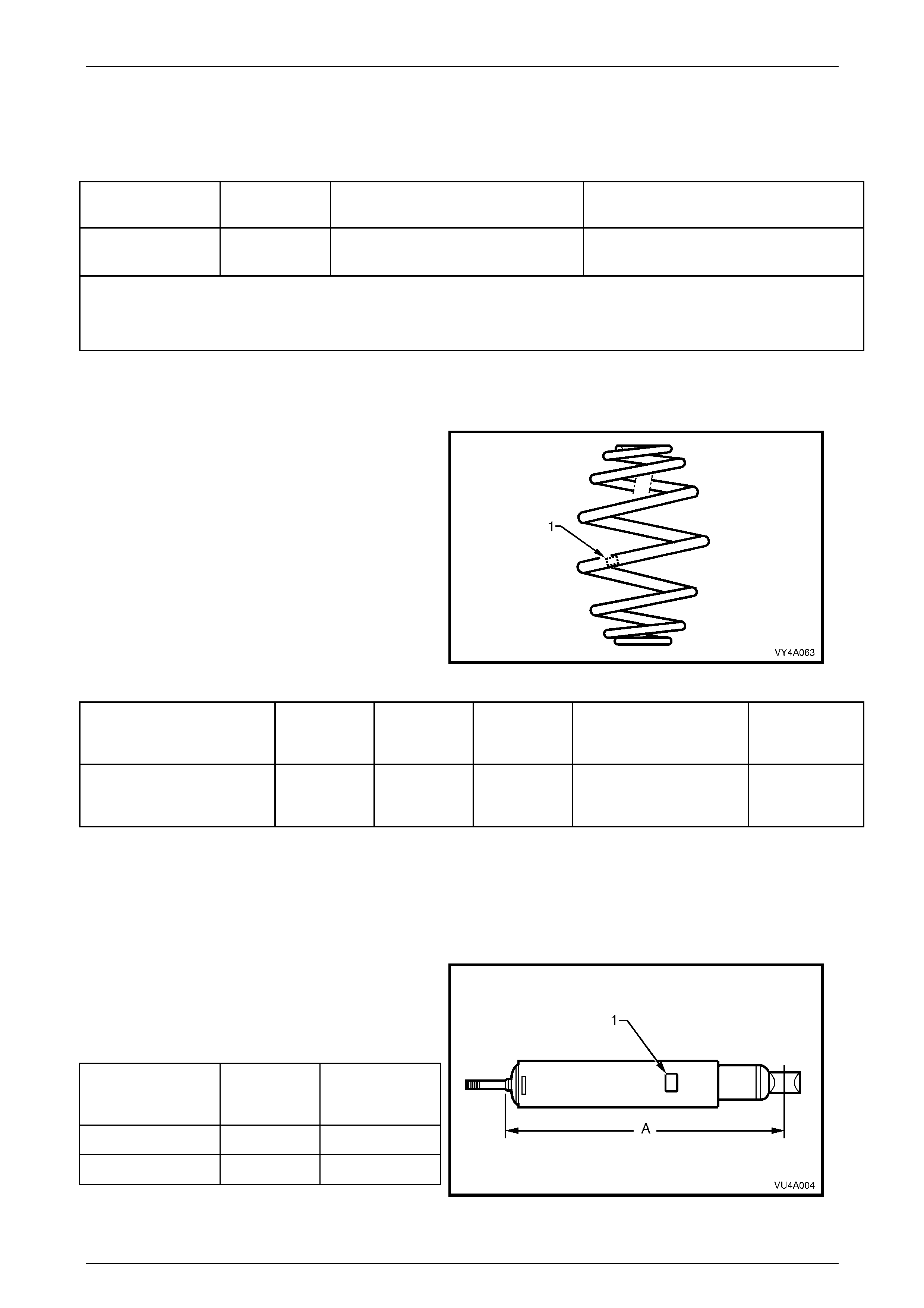
Rear Spring Details
Type Variable rate 'Minibloc'
Identification of the rear spring fitted to a particular
vehicle can be achieved by cross-referencing the two
digit code, which is provided on the production
identification tag (1) with the table below.
Figure 4A-30
SUSPENSION
CONFIGURATION NUMBER
OF COILS FREE
LENGTH
(mm)
OUTSIDE
DIAMETER
(mm)
SPRING TYPE AND
RATE PRODUCTION
ID CODE
Wagon FE1 7.8 320 165 +0/–20 Variable
51 N/mm – 90 N/mm
(5300 N @ 205 mm)
AC
Rear Shock Absorber Details
Type
Production Option FE1 (Low Series) Twin tube hydraulic, gas pressurised
Production Option FX3 (High Series) Twin tube hydraulic, gas pressurised
Identification of the rear shock absorber fitted to a
particular vehicle can be achieved by cross-referencing
the two digit code which is provided on the production
identification tag (1) with the table below.
The table also provides nominal extended lengths (A).
SUSPENSION
CONFIGURATION NOMINAL
EXTENDED
LENGTH
PRODUCTION
ID CODE
A WD Wagon – FE1 585 BX/BY
A WD Wagon – FX3 585 BX/BY
Figure 4A-31
Rear Suspension Page 4A-27
Page 4A-27
Rear Stabiliser Bar Details
Identification of the rear stabiliser shaft fitted to a
particular vehicle can be achieved by cross-referencing
the two digit code which is provided on the production
identification tag (1) with the table below.
The table also provides stabiliser bar diameters (2).
SUSPENSION
CONFIGURATION DIAMETER
(mm) PRODUCTION
ID CODE
Wagon FE1 13 FL
Figure 4A-32
Rear Suspension Page 4A-28
Page 4A-28
5 Torque Wrench Specifications
ATTENTION
Throughout this section, fastener torque wrench specifications may be accompanied with the following
identification marks:
! Fasteners must be replaced after loosening.
" Fasteners either have micro encapsulated sealant applied or incorporate a mechanical thread lock and
should only be re-used once. If in doubt, replacement is recommended.
# Vehicle must be at curb height before final tightening.
If one of these identification marks is present alongside a fastener torque wrench specification, the
recommendation regarding that fastener must be adhered to.
NOTE
Only those torque specifications specifically
related to the service operations detailed in this
section, are detailed here. For any remaining
specifications, refer to Section 4A Rear
Suspension, in either the MY 2003 VY and V2
Series or WK Service Information.
% Additional Control Arm Adjusting Shaft Lock Nut................................................................... 50 Nm
Brake Caliper to Anchor Plate Bolt.........................................................................................85 Nm
! Collar Nut to Outer Rear Wheel Driveshaft..........................................................................300 Nm
Rear Dust Shield to Rear Suspension Control Arm Upper bolt..........................................75 Nm
Lower bolt..........................................88 Nm
"
""
" #
##
# Rear Suspension Control Arm to Rear Suspension Crossmember Nut...............................100 Nm
! Rear Suspension Crossmember Front Mount to Underbody Bolt............................... 125 Nm, then
35° turn angle
"
""
" Rear Suspension Crossmember Front Mounting Brace Bolt.................................................. 70 Nm
! Rear Suspension Crossmember Rear Mount to Final Drive, Rear Cover Bolt.......................95 Nm
! Rear Suspension Crossmember Rear Mount to Underbody Bolt.................................. 35 Nm, then
60° turn angle
Road Wheel Attaching Nut...................................................................................................125 Nm
Rear Suspension Page 4A-29
Page 4A-29
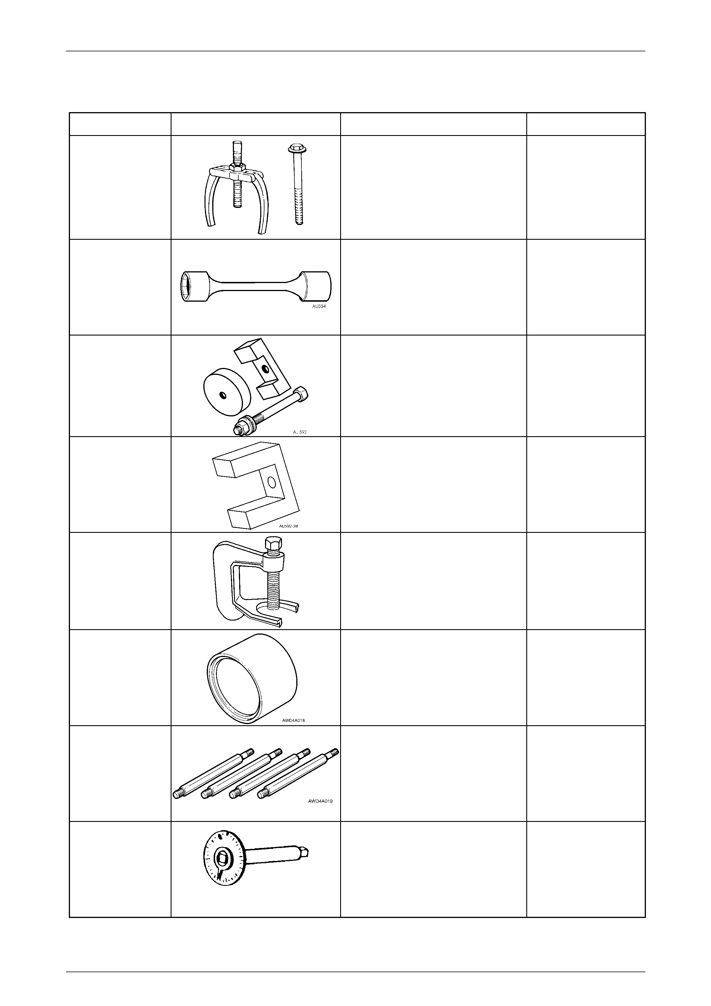
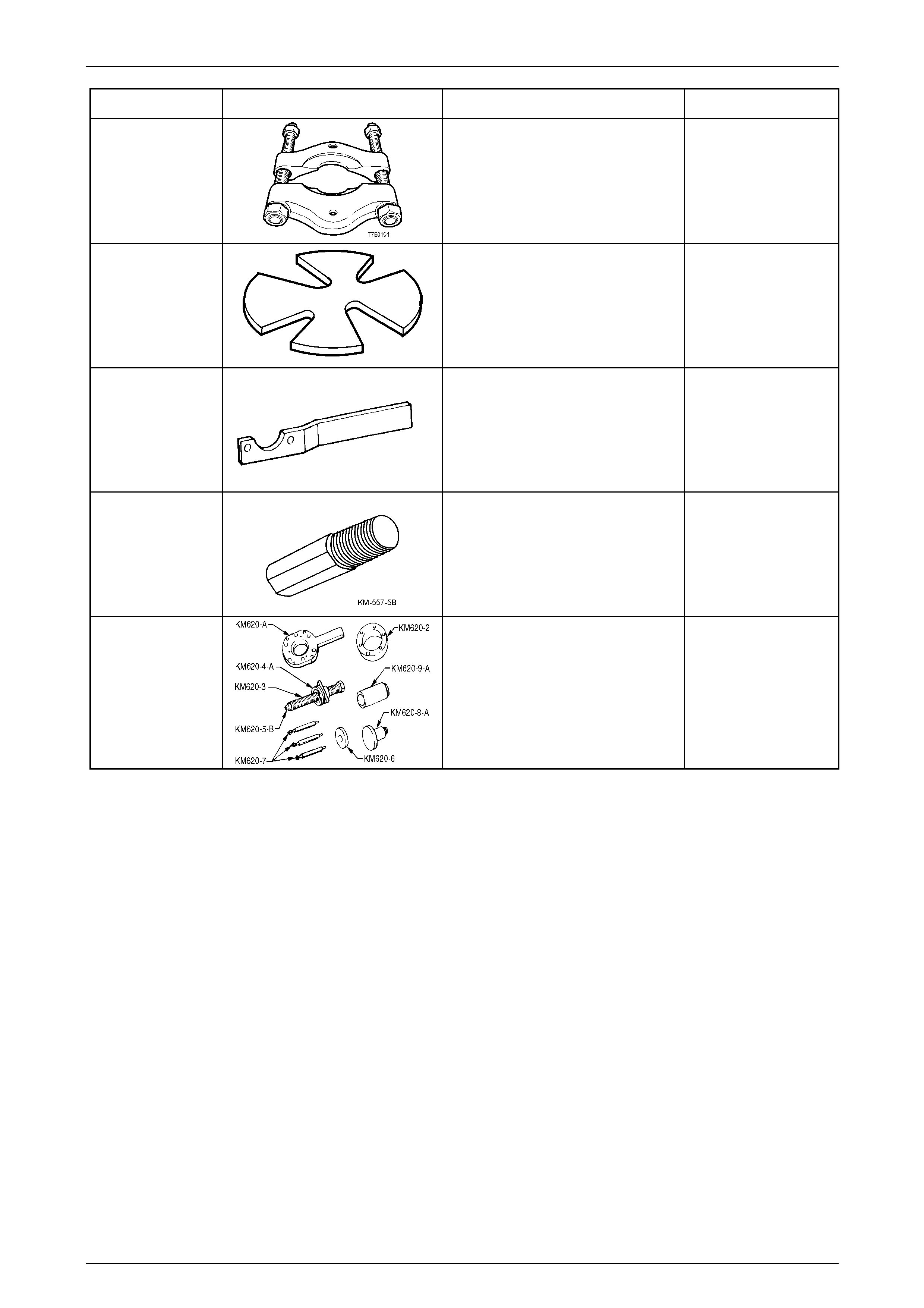
6 Special Tools
Tool Number Illustration Description Tool Classification
AMKM-557
Puller
Used for removing bushing from
crossmember front mounti ng with the
crossmember removed from the
vehicle.
Previously released.
Desirable
AU 534
Torque Limiting Socket
Used in conjunction with an impact
gun to tighten wheel nuts.
Previously released.
Mandatory
AU 592
Bush Remover/Installer
Used to remove and install the rear
crossmember, front bush when the
crossmember remains installed.
Previously released.
Desirable
AU 592-3B
Support Block
Used with the plate, bolt and nut of
AU 592 to install the bushing into the
front of the rear crossmember.
New release.
Available
C4150-C
Stud Remover
Used to remove the wheel studs from
the rear trunnion.
Previously released.
Unique
CH-47575
Rear Wheel Bearing Receiver
Used to support the trailing arm
bearing hub.
New release.
Mandatory
DT-47574
Stand Offs
Used with selected components of
Tool No. KM 620-1A when installing a
new rear wheel bearing.
New release.
Mandatory
E7115
Angle Wrench
Used to tighten fasteners whenever a
turn angle torque is specified.
Previously released.
Mandatory
Rear Suspension Page 4A-30
Page 4A-30
Tool Number Illustration Description Tool Classification
J22912-01
Press Plates
Used for various pressing operations.
Previously released.
Desirable
KM 307-B
Press Plates
Used to support rear trunnion during
trunnion removal.
Previously released.
Desirable
KM 468
Holding Bar
Used with two wheel nuts, to hold the
rear trunnion.
Previously released.
Unique
KM 557-5B
Adaptor
Used with AU 592-2 and AMKM-557
to remove the rear crossmember front
mount when the crossmember has
been removed from the vehicle.
New release.
Available
KM 620-1A
Remover/Installer
Used to remove and install rear wheel
driveshaft flange, rear wheel bearing
and outer rear wheel driveshaft.
Also rel eas ed as J- 4209 4.
Previously released.
Unique