
Rear Final Drive & Driveshafts Page 4B1–1
Page 4B1–1
Section 4B1
Rear Final Drive & Driveshafts
ATTENTION
Before performing any Service Operation or other procedure described in this Section, refer to Section 00
Cautions And Notes for correct workshop practices with regard to safety and/or property damage.
1. General Description............................................................................................................................... 2
1.1 Final Drive Assembly Identification......................................................................................................................5
1.2 Final Drive Lubricant..............................................................................................................................................6
2. Minor Service Operations.....................................................................................................................7
2.1 General Information ...............................................................................................................................................7
Road Wheel Requirements....................................................................................................................................7
2.2 Driveshaft Assembly..............................................................................................................................................8
Remove ...................................................................................................................................................................8
Reinstall ..................................................................................................................................................................8
2.3 Driveshaft and/or Constant Velocity Joints.........................................................................................................9
Disassemble ...........................................................................................................................................................9
Inspect...................................................................................................................................................................10
Driveshaft and Boots ........................................................................................................................................10
Constant Velocity Joints ...................................................................................................................................11
Reassemble ..........................................................................................................................................................12
Constant Velocity Joints ...................................................................................................................................12
Driveshaft and Boots ........................................................................................................................................14
2.4 Pinion Oil Seal......................................................................................................................................................16
Replace .................................................................................................................................................................16
2.5 Pinion Flange ........................................................................................................................................................19
Replace .................................................................................................................................................................19
Using Old Seal..................................................................................................................................................19
Using New Oil Seal...........................................................................................................................................21
3 Major Service Operations ................................................................................................................... 25
3.1 Trailing Arm Trunnion Flange, Trunnion Assembly and/or Wheel Bearing....................................................25
3.2 Rear Final Drive Assembly..................................................................................................................................26
Remove .................................................................................................................................................................26
Reinstall ................................................................................................................................................................31
3.3 Removed Final Drive Assembly..........................................................................................................................36
4 Specifications....................................................................................................................................... 37
6 Torque Wrench Specifications........................................................................................................... 38
7 Special Tools........................................................................................................................................ 39
Techline
Techline
Techline
Techline
Techline
Techline

Rear Final Drive & Driveshafts Page 4B1–2
Page 4B1–2
1. General Description
Independent rear suspension is fitted as standard equipment on all MY 2004 AWD Wagon models and all are fitted with
a final drive assembly that has a four pinion type rear differential assembly. The final drive ratio is 3.46:1.
As the standard fitment Traction Control System requires independent control of each rear wheel, the Limited Slip
Differential (LSD) option is not available, in this vehicle.
The final drive assembly is mounted directly to a crossmember which is rubber mounted to the vehicle underbody. The
differential case and drive pinion are mounted in opposed taper roller bearings in the carrier. Differential case side
bearing pre-load adjustment is provided by screw adjusters in the sides of the case. Pinion bearing pre-load is provided
by a collapsible spacer. Torque is transferred from the propeller shaft to the final drive assembly via the pinion flange
which is splined to the hypoid pinion. The torque is then transferred from the pinion through the ring gear, differential
case, differential pinion cross shafts, differential pinions, side gears and then via splines, to the inner axle shafts and
driveshafts.
The final drive assembly should be removed from the vehicle for all service operations other than the removal of the
inner axle shafts, inner axle shaft oil seals, pinion oil seal or the rear cover.
Two driveshaft assemblies are fitted, each consisting of a shaft which is splined at each end into ball type constant
velocity joints. The inner constant velocity joint is bolted to the inner axle shaft flange at the differential carrier, with the
outer joint bolted to the trunnion flange at the rear trailing arm. Both joints are of the ‘plunge’ type design.
With the following exceptions, MY 2004 AWD Wagon Series Final Drive and Driveshafts Service Information carries over
from MY 2003 VY Series vehicles:
• Final Drive Pinion Flange and/or Seal.
• Driveshafts.
For information not contained within this Section, (including all Final Drive Assembly Maintenance items), refer to
MY 2003 VY and V2 Series Service Information, Section 4B Final Drive and Driveshafts.
Rear Final Drive & Driveshafts Page 4B1–3
Page 4B1–3
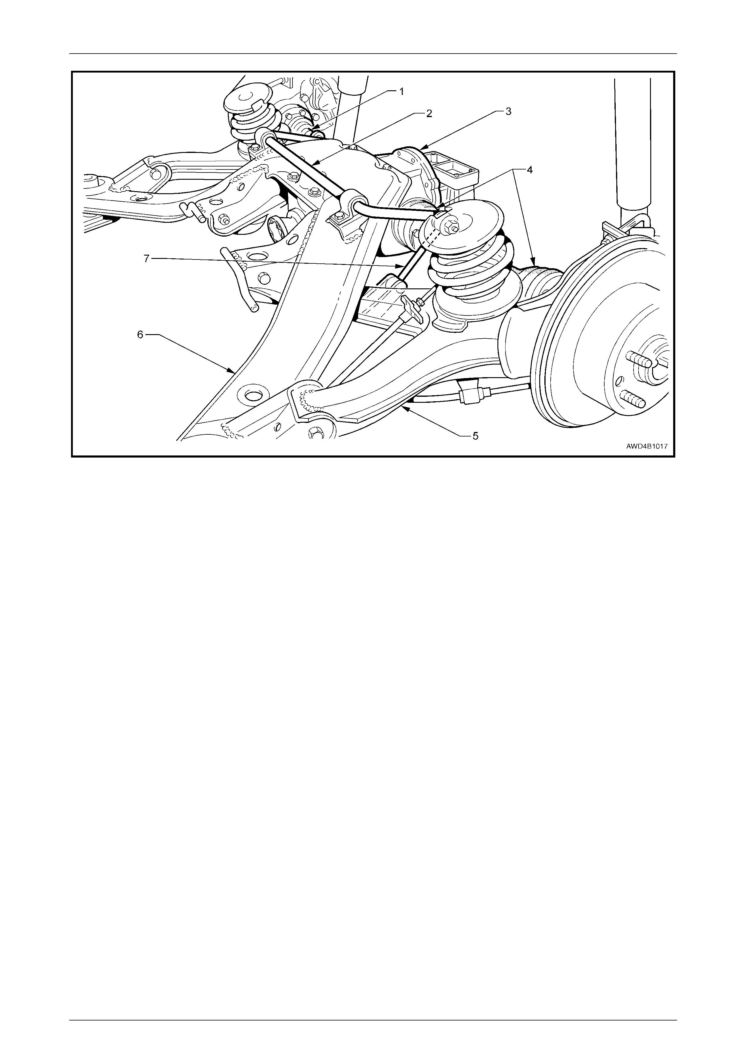
Figure 4B1 – 1
Legend
1 Driveshaft
2 Rear Suspension Stabiliser Bar
3 Final Drive Assembly
4 Constant Velocity Joints
5 Trailing Arm
6 Rear Suspension Crossm ember
7 Rear Stabiliser Bar to Trailing Arm Link
Rear Final Drive & Driveshafts Page 4B1–4
Page 4B1–4
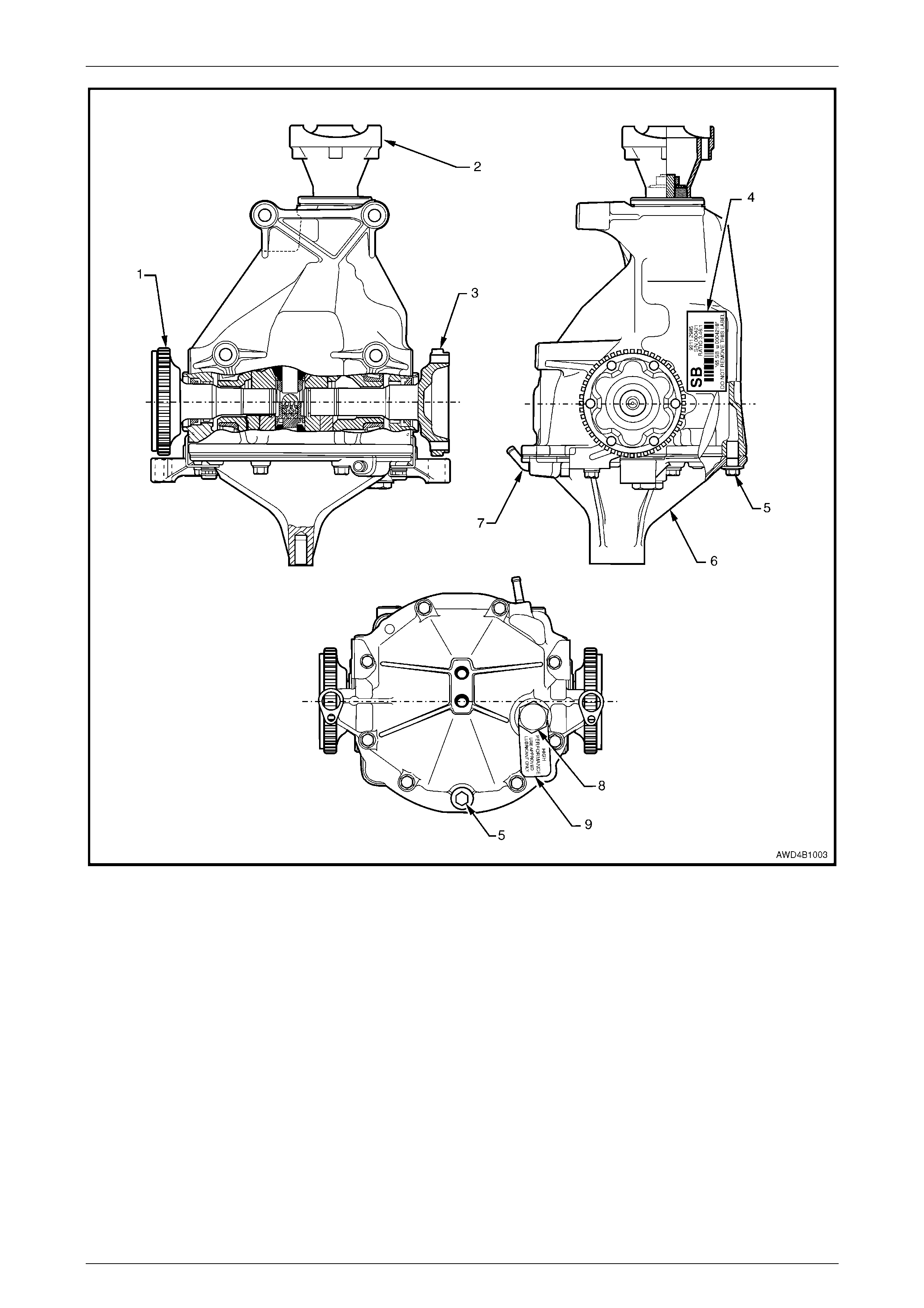
Figure 4B1 – 2
Legend
1 LH Inner Axle Shaft
2 Pinion Flange
3 RH Inner Axle Shaft
4 Identification Label
5 Drain Plug
6 Rear Cover
7 Breather
8 Filler Plug
9 Lubrication Tag
Rear Final Drive & Driveshafts Page 4B1–5
Page 4B1–5
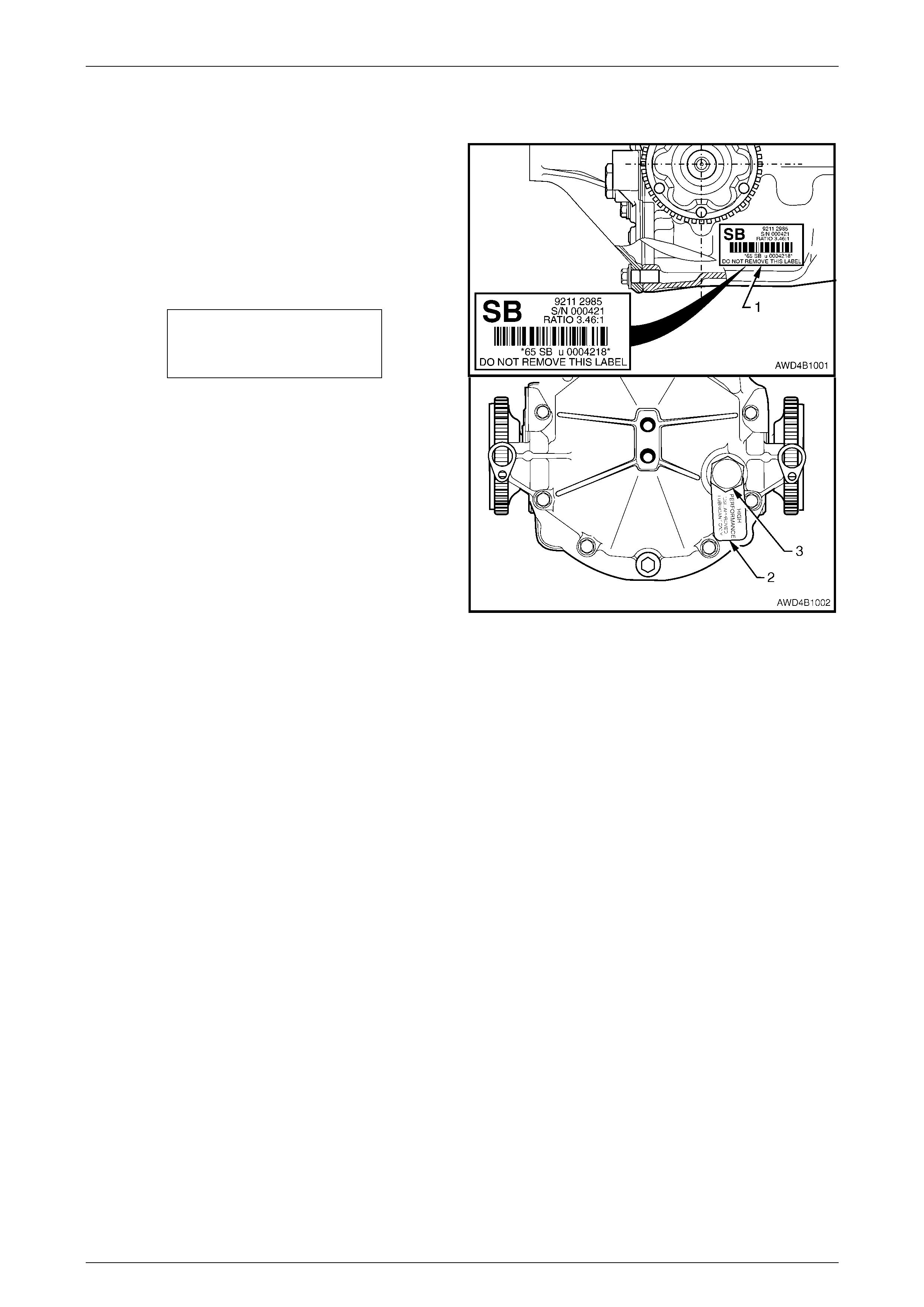
1.1 Final Drive Assembly Identification
The type of differential fitted to this final drive assembly can
be identified by referring to the identification label (1)
attached to the RHS of the carrier housing.
The identification label (1) carries the final drive assembly
part number for the final drive ratio and the serial number of
the assembly.
The inform ation on the lubrication tag (2) under the filler
plug (3), will be:
HIGH
PERFORMANCE
USE APPROVED
LUBRICANT ONLY
Figure 4B1 – 3

Rear Final Drive & Driveshafts Page 4B1–6
Page 4B1–6
1.2 Final Drive Lubricant
Should the final drive assembly require the lubricant to be replaced, then the only lubricant that is to be used, is a
Synthetic Hypoid Gear Oil, with a viscosity, SAE 80W -140, such as; MOBIL Mobilube SHC ID or CASTROL SAF-XA.
Rear Final Drive & Driveshafts Page 4B1–7
Page 4B1–7
2. Minor Service Operations
2.1 General Information
ATTENTION
All fasteners are important attaching parts as they affect the performance of vital components and/or could
result in major repair expense. Where specified in this section, fasteners MUST be replaced with parts of the
same part number or an approved equivalent. Do not use fasteners of an inferior quality or substitute design.
Torque values must be used as specified during reassembly or reinstallation of all components, to ensure
correct retention.
Throughout this section, fastener torque wrench specifications may be accompanied with the following
identification marks:
!
!!
! Fasteners must be replaced after loosening.
"
""
" Vehicle must be at curb height before final tightening.
#
##
# Fasteners either have micro encapsulated sealant applied or incorporate a mechanical thread lock and
should only be re-used once. If in doubt, replacement is recommended.
If one of these identification marks is present alongside a fastener torque wrench specification, the
recommendation regarding that fastener must be adhered to.
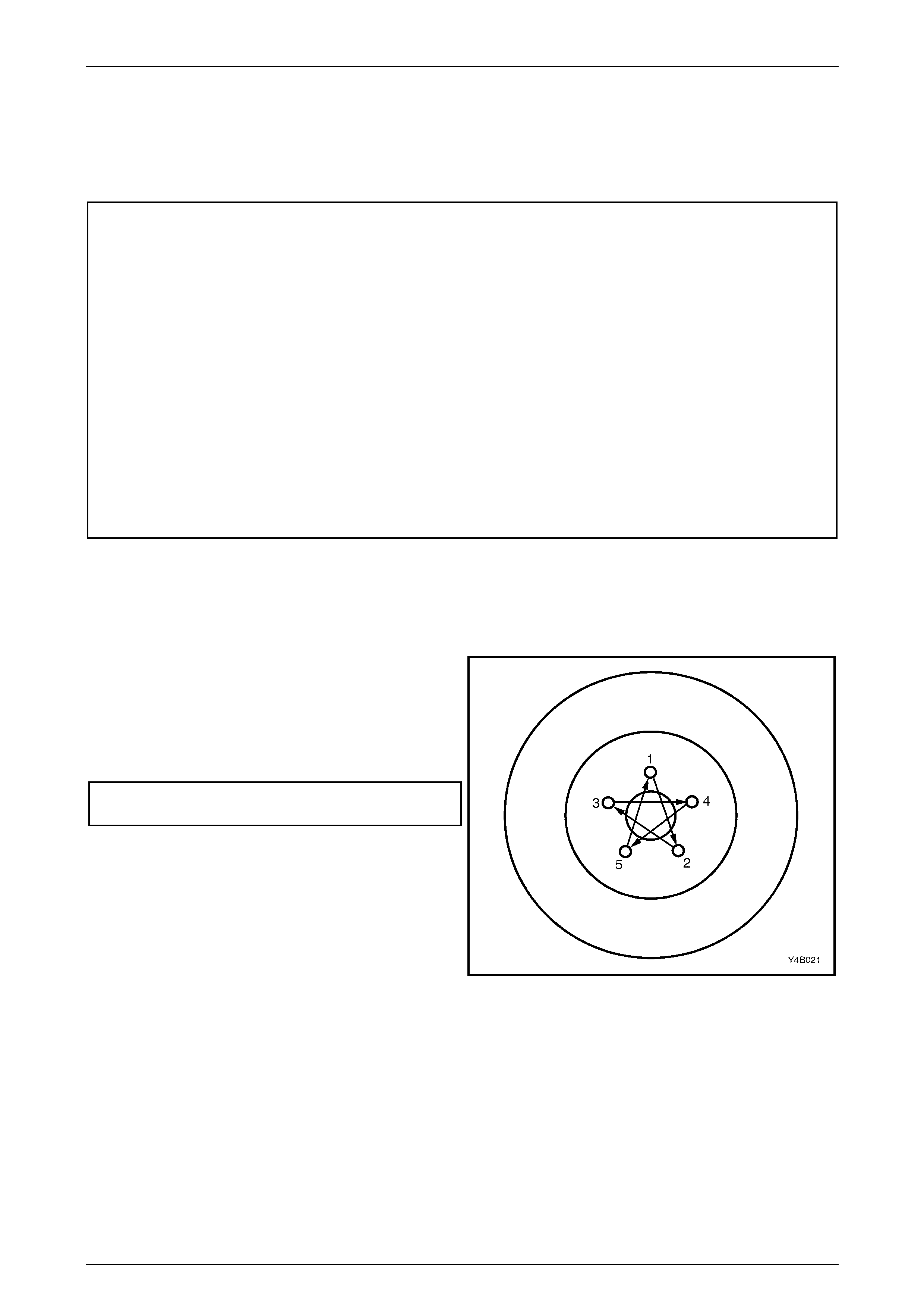
Road Wheel Requirements
1 Whenever a road wheel and/or brake disc is removed from the vehicle, the relationship of the road wheel and the
disc to the hub MUST be marked with a felt tipped pen or similar, in order for those parts to be reinstalled in their
original positions. This is critical to maintain the brake disc and road wheel runout dimension to a minimum.
2 When reinstalling road wheels, do not use an impact
gun to tighten wheel nuts unless the impact gun is
fitted with a torque limiter socket (Tool No. AU 534 or
a commercial equivalent). Failure to correctly tighten
wheel nuts to the correct torque specification and in
the correct order, may result in a distorted brake disc,
leading to the development of brake shudder.
Road Wheel Attaching Nut
Torque Specification....................................... 125 Nm
NOTE:
For a complete description of the method used
to measure both brake disc and trunnion
assembly runout and correction, refer to
3.5 Rear Brake Disc, Brake Disc and Hub
Indexing Procedure in Section 5A Service and
Park Braking Systems, in the MY 2003 VY and
V2 Series Servic e Information. Figure 4B1 – 4
Rear Final Drive & Driveshafts Page 4B1–8
Page 4B1–8
2.2 Driveshaft Assembly
LT Section No: 05-290
ATTENTION
The following fasteners MUST be replaced when performing these operations:
!
!!
! All removed driveshaft constant velocity joint attaching bolts.
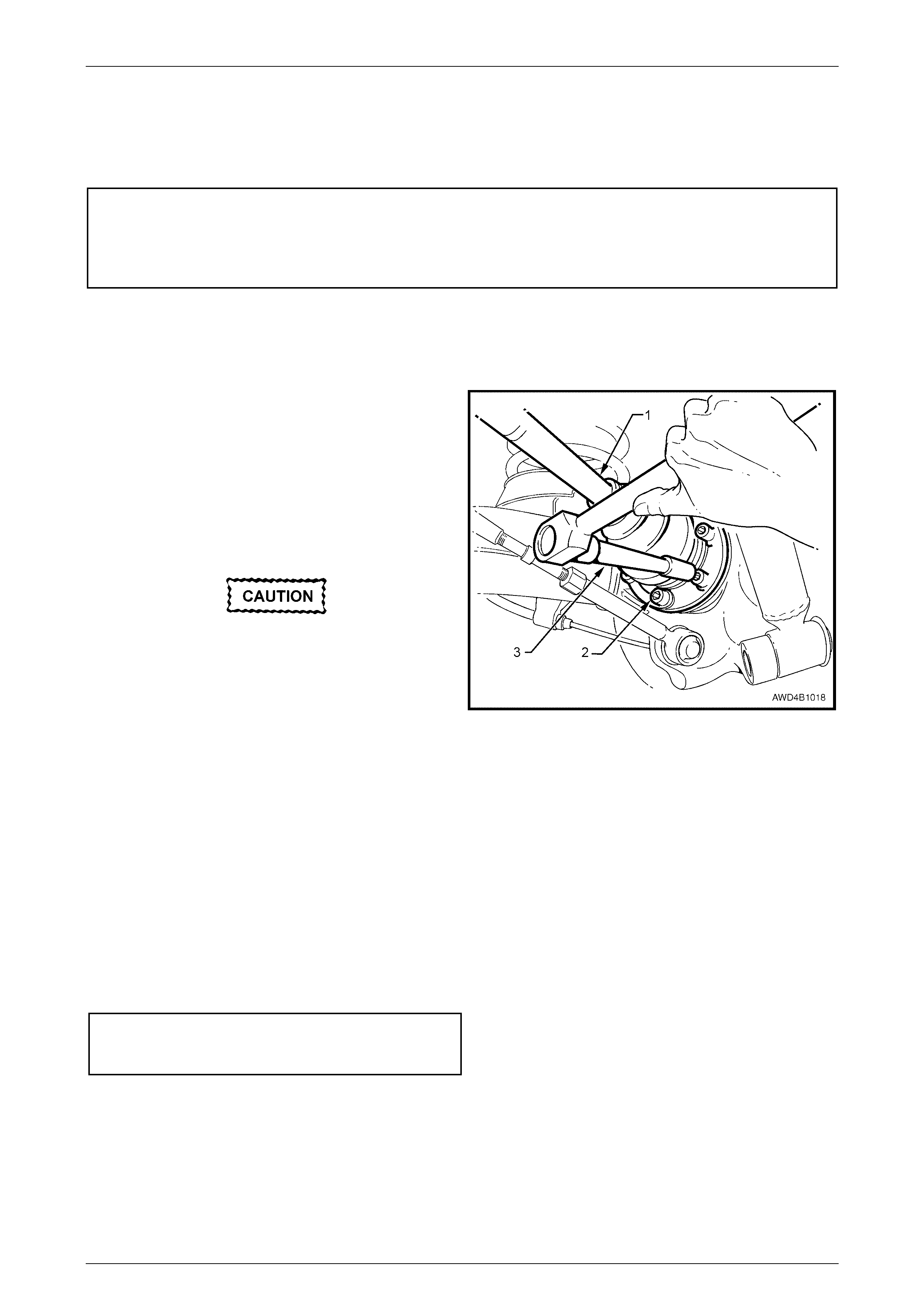
Remove
1 Raise the rear of vehicle and support in a safe mann er. Ref er to Section 0A General Information, in the MY 2003
VY and V2 Series Service Information, for the location of jacking points.
2 Use a felt tipped pen or similar, to identify the
driveshaft as being either right or left and also, which
constant velocity joint is the outer.
NOTE
Even though both inner and outer constant velocity
j
oints are of the plunge design, it is important that the
driveshaft orientation is marked, to maintain the shaft
‘wind-up’ direction when reinstalled.
During driveshaft removal and reinstallation,
the driveshaft 'free' end MUST be supported
to keep constant velocity joint angles to a
minimum. Excessive angles and/or dropping
the 'free' end will cause damage to the boot
cap and the joint itself.
3 With the park brake firmly applied, use an 8 mm Allen
key socket and suitable socket equipment (3) to
remove the driveshaft, inner constant velocity joint to
inner axle shaft and outer constant velocity joint to
trunnion flange attaching bolts (2) (six places) and
plates, remove driveshaft (1).
Figure 4B1 – 5
Reinstall
Reinstallation of the driveshaft is reversal of the removal procedure, noting the following points.
1 When reinstalling the driveshaft, ensure that either constant velocity joint is not deflected excessively and that the
orientation is the same as before removal, using the identification marks previously applied.
2 Reinstall the driveshaft, then six NEW bolts and three plates at each end, tightening to the correct torque
specification.
( ! ) Driveshaft constant velocity joint
attaching bolt torque specification........................50 Nm
then 70° turn angle
Rear Final Drive & Driveshafts Page 4B1–9
Page 4B1–9
2.3 Driveshaft and/or Constant Velocity
Joints
LT Section No: 05-290
There are two repair kits available for driveshaft constant velocity joint repairs:
a A ‘Boot Kit’, which consists of a boot, boot clamps and retaining circlip.
b A ‘Constant Velocity Joint Kit’, which contains the same items as the Boot Kit plus the constant velocity joint and
lubricant of the correct type and quantity.
NOTE
Sealant for the constant velocity joint covers is
not supplied. Refer to 4 Specifications, in this
Section for the recommended type.
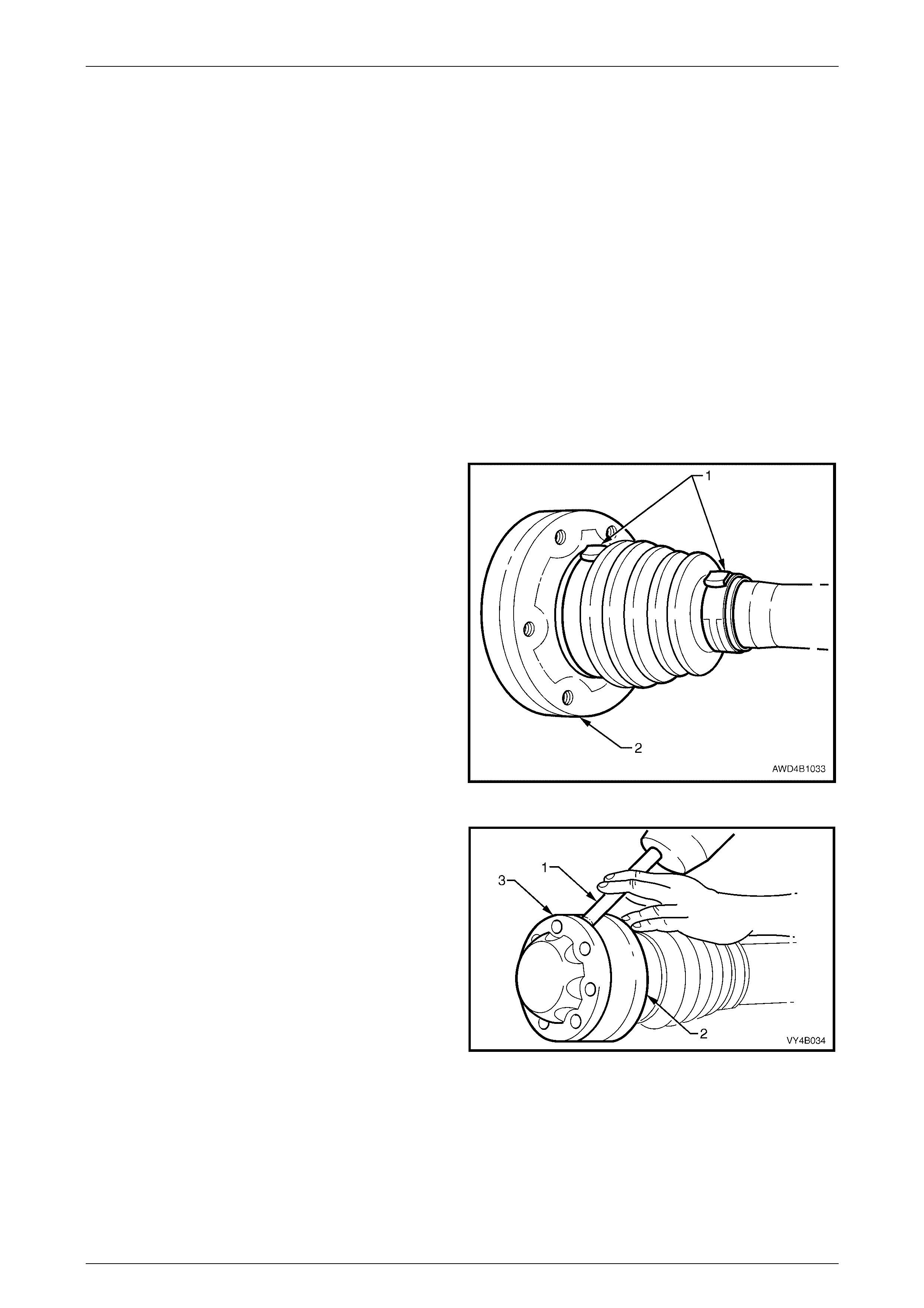
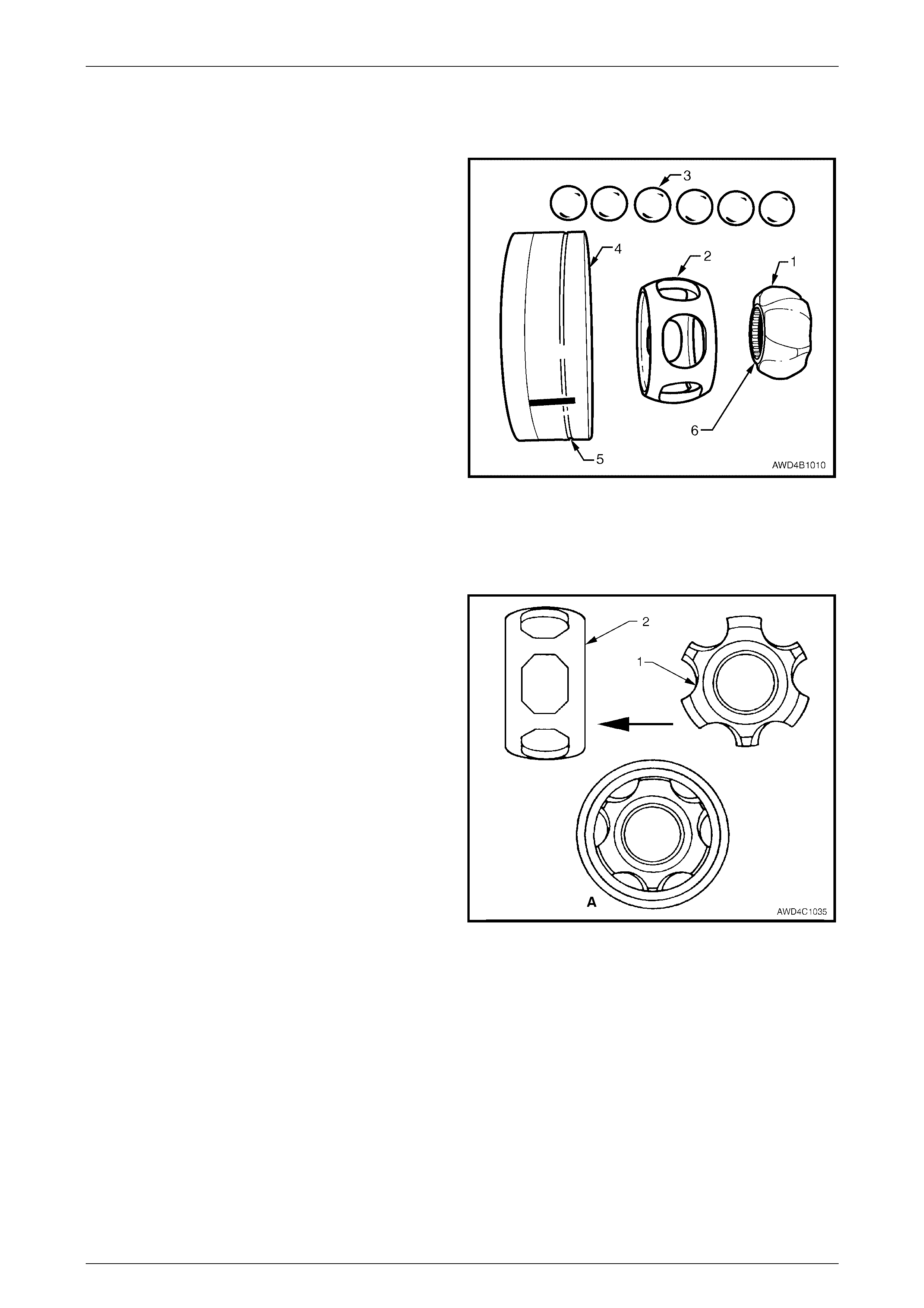
Disassemble
1 Remove driveshaft assembly, refer to 2.2 Driveshaft
Assembly in this Section.
2 Clean outside of assembly with a suitable solvent
before disasse mbl ing.
3 Using metal shears or other suitable cutting tool, cut
boot clamps (1) in the raised crimped area, then
remove the clamps and discard.
4 Clamp assembly, by the constant velocity joint (2), in a
vice fitted with soft metal jaws.
Figure 4B1 – 6
5 Using a suitable drift (1) and hammer, tap end dust
shield cap (3) from the outer end of the constant
velocity joint.
6 After changing the clamping, use a similar procedure
to dislodge the inner dust shield (2) from the constant
velocity joint.
Figure 4B1 – 7
Rear Final Drive & Driveshafts Page 4B1–10
Page 4B1–10
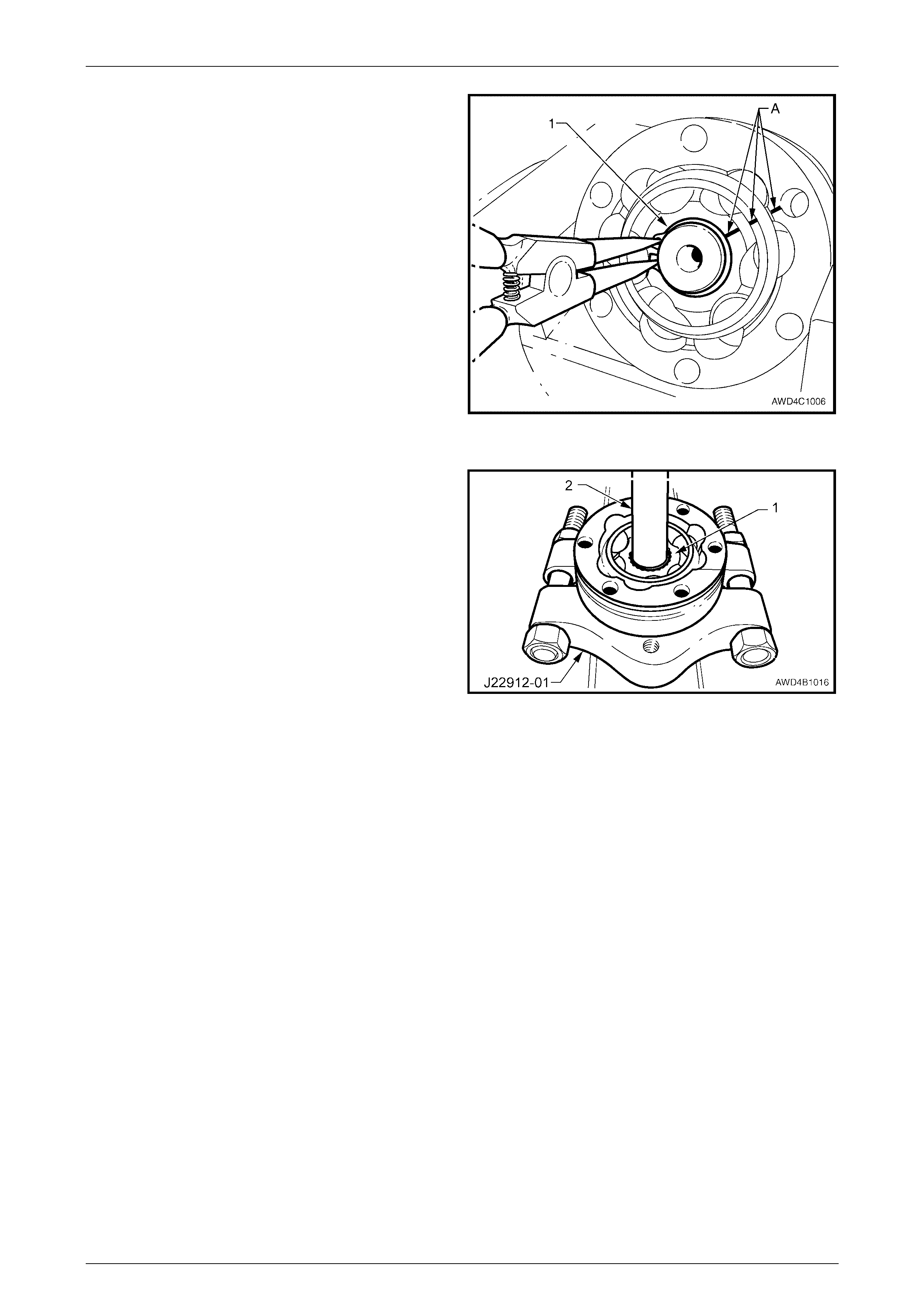
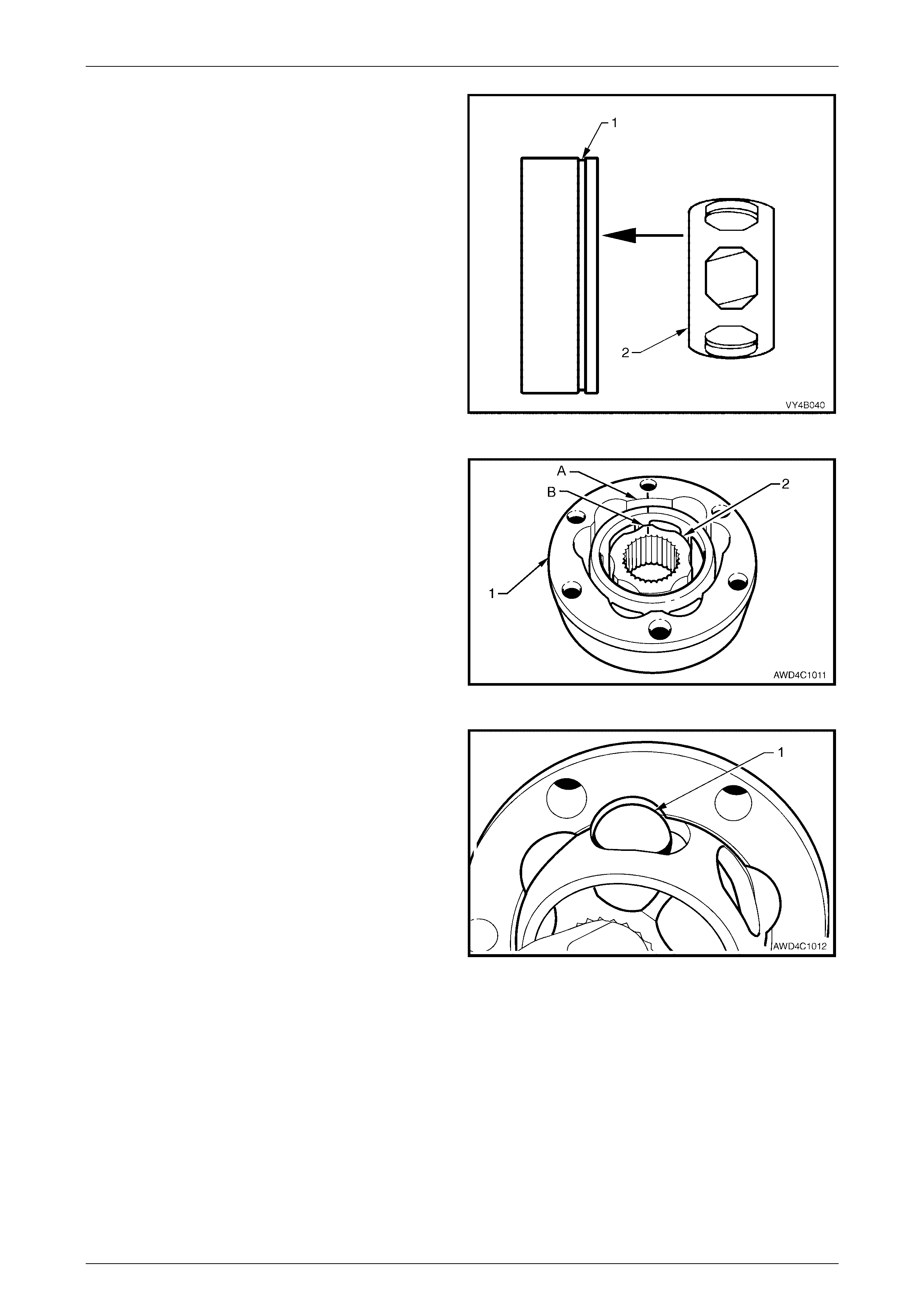
7 Using suitable circlip pliers, remove the circlip (1) from
the end of driveshaft where the constant velocity joint
is to be removed. Discard the removed circlip.
NOTE
Do not re-use circlips once they have been
removed. Always use new snap rings on
reassembly.
8 Wipe the excess lubricant from the outer joint surfaces
then apply correction fluid across the inner race, ball
carrier and outer race as indicated by 'A'.
NOTE
This step is necessary to maintain the original
relationship of these three components.
9 Remove assembly from vice. Slide inner dust shield
and boot towards the centre of the driveshaft.
Figure 4B1 – 8
10 Using suitable press plates (such as Tool No. J22912-
01), supporting inner race (1), press driveshaft from
constant velocity joint, using a suitable drift (2).
NOTE
While the press plates must support the inner
race, if clamped too tight to the driveshaft, then
the splines will foul against the press plates.
11 Repeat process to remove remaining constant velocity
joint, as required.
12 Remove boots and dust shields from driveshaft,
ensuring boots are not damaged on edges of shaft
splines. Figure 4B1 – 9
Inspect
Driveshaft and Boots
1 Clean shaft and boot/s in a suitable cleaning solvent.
2 Inspect driveshaft for tw isti ng, cracking or excessive spline wear.
NOTE
As the interconnecting shaft is not serviced
separately, if found to be defective, then the
complete driveshaft must be replaced.
3 Inspect boots and replace if split, fatigued, cracked or worn.
Rear Final Drive & Driveshafts Page 4B1–11
Page 4B1–11
Constant Velocity Joints
Complete disassembly of the constant
velocity joints is not recommended. The
internal components are a precision fit and
develop their own characteristic wear
patterns. Intermixing components could
result in looseness, binding and/or premature
failure of the joint.
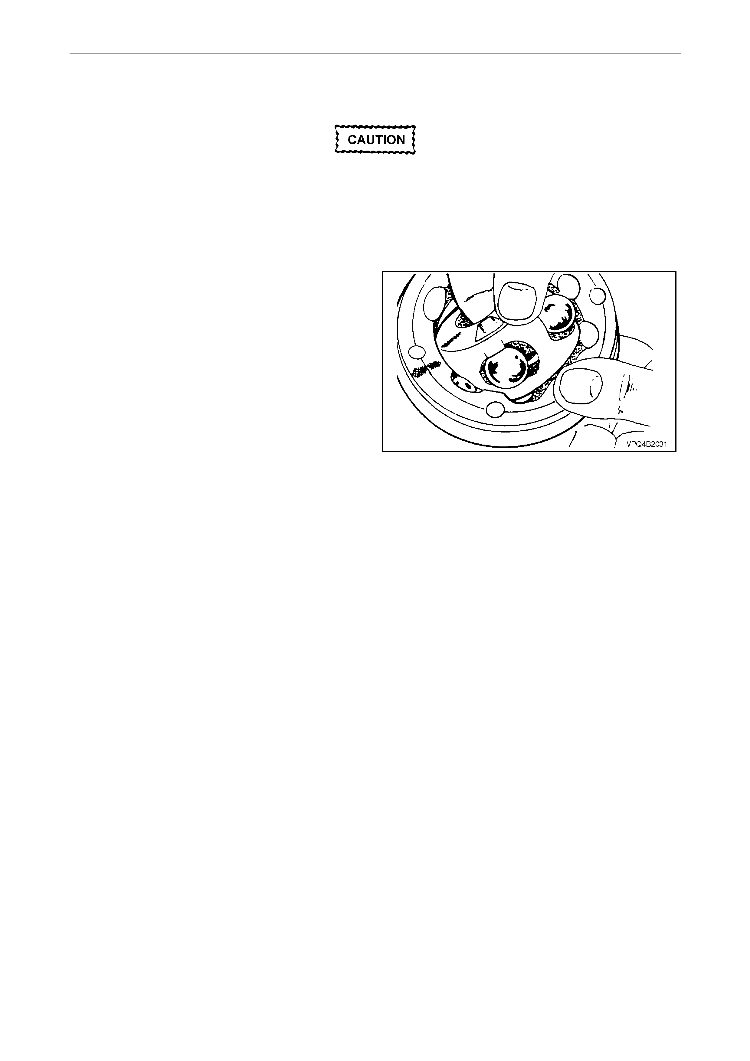
1 Inspect grease in joint and, if obviously contaminated
with and/or has been subjected to dirt/water ingress,
the joint has in all likelihood suffered damage and
sh ould be replaced.
2 If inspection reveals that the joint has not been
contaminated, clean joint by soaking in a suitable
cleaning solvent.
3 Once grease has been removed, inspect internal
components by tilting inner race to one side to expose
each ball.
NOTE
Take care not to pivot the inner race too sharply,
as the balls can become dislodged. If this does
occur and the original location of the balls is lost,
then the constant velocity joint should be
replaced.
Figure 4B1 – 10
4 Replace joint assembly if there is severe pitting, galling, play between balls and the cage windows, any cracking or
damage to cage, outer race, pitting or galling or chips in raceways.
Rear Final Drive & Driveshafts Page 4B1–12
Page 4B1–12
Reassemble
Constant Velocity Joints
NOTES
• During the removal, cleaning, inspection or
replacement of a constant velocity joint, it is
possible for the joint to become
disassembled. Should an inadvertent
disassembly of a constant velocity joint
occur, and notwithstanding the earlier
recommendation, it is possible to reassemble
the constant velocity joint, provided the
following procedure is followed EXACTLY.
• The inner race (1) and cage (2), together with
the individual balls (3), should be maintained
in their original locations to minimise the
creation of a noisy joint.
• Under no circumstances are components
from one constant velocity joint to be mixed
with components from another constant
velocity joint.
Shown in Figure 4B1-11 is an exploded view of one
constant velocity joint. As each are of the plunge design,
this view is suitable for either joint. Note the single
identification groove (5) on the outer race (4) and the
identification step (6) on the inner race.
Figure 4B1 – 11
1 Place the inner race (1) into the cage (2) and position
centrally.
Figure 4B1 – 12
Rear Final Drive & Driveshafts Page 4B1–13
Page 4B1–13
2 Place the inner race and cage assembly (2) into the
outer race (1). Make sure that the identification groove
(1) and step (2) are on opposite sides of the assembly,
as shown.
Figure 4B1 – 13
3 Align the thick sections (A) on the outer race (1) , with
the narrow ones (B) on the inner race (2), aligning the
three marks mad e bef ore dis assembly.
Figure 4B1 – 14
4 Tilt the cage and inner race, as shown and fit one ball
(1).
Repeat this process for the remaining five balls.
Figure 4B1 – 15
Rear Final Drive & Driveshafts Page 4B1–14
Page 4B1–14
5 When assembly of the constant velocity joint is
complete, check for plunge movement of the inner
members, as indicated by ‘A’. If NO plunge movement
can be achieved, then the constant velocity joint has
been incorrectly asse mbl ed.
If such a situation occurs, the constant velocity joint
must be disassembled and the assembly process
repeated until such time that the required plunge
movement is achieved.
NOTE
This check applies to both constant velocity
joints fitted to the rear driveshafts on the
MY2004 AWD Wagon.
Figure 4B1 – 16
Driveshaft and Boots
1 Remove old sealing bead of silicon from dust shields, dust caps and constant velocity joints.
2 Slide a NEW sma ll boot cla mp over the driveshaft, then insta ll both dust shield and boot assembl ie s onto
driveshafts, ensuring that boots are not damaged by sharp edges on each end by the shaft splines.
3 Position NEW large boot clamp over boot (2) and
place boot over dust shield (1). Using Tool No.
J22610, se curely crimp b oot cl amp, ens urin g the crimp
is positioned mid-way between two bolt holes (3, in
view ‘A’).
Figure 4B1 – 17
4 Pack inside section of joint and boot with one tube of grease (40 grams) and pack half tube (20 grams) to outside
section of joint. Work the joint by hand to distribute grease onto all surfaces, inside the joint.
5 Using a suitable size tube (3), press the constant
velocity joint (2) onto the driveshaft, ensuring that the
press load is taken by the inner race (1).
6 Install a NEW circlip to secure the constant velocity
joint, at each end.
Figure 4B1 – 18
Rear Final Drive & Driveshafts Page 4B1–15
Page 4B1–15
7 Apply a 2 mm diameter bead (4) of commercially
available RTV 732 sealant to dust caps/shields. Take
care not to contaminate the constant velocity joint
grease with sealant.
Figure 4B1 – 19
8 Position dust caps and du st sh ield s onto con stan t
velocity joints, ensuring that all bolt holes align.
NOTE
Temporarily install three of the retaining bolts to
assist with the alignment.
9 Using a suitable punch and ha mmer , tap caps and
shields into place.
Figure 4B1 – 20
10 Place new small boot clamps onto driveshaft. Do not crimp the small boot at this time.
11 Locate sm all ends of boots into boot grooves on
driveshafts, ensuring that boots are not twisted.
With each joint, pry up the small ends of boots from
the shaft (1) to equalise air pressure inside and
outside of boots and work out any dimples before
crimping the small clamp/s.
The location distance ’A’, applies to both the
inner and outer joints, as both are the plunge
type (MY 2004 AWD Wagon only) and should
be set at 81 mm before applying the small
clamp.
Figure 4B1 – 21
12 Position small clamps over en ds of boots and usi ng
Tool No. J22610, crimp ends of clamps until a gap
between the clamp 'ears' of 1 to 2 mm is achieved.
13 Reinstall driveshaft, refer to 2.2 Driveshaft Assembly –
Reinstall in this Section.
Figure 4B1 – 22

Rear Final Drive & Driveshafts Page 4B1–16
Page 4B1–16
2.4 Pinion Oil Seal
LT Section No: 05-290
Replace
1 Using a floor jack under centre of differential carrier, jack up rear of vehicle, then place safety stands under trailing
arms.
2 Mark the position of the propeller shaft rear coupling to pinion flange, using a felt tipped pen or similar.
3 Remove propeller shaft, refer to Section 4C1 Propeller Shaft and Universal Joints, in the MY 2004 AWD Wagon
Service Information. This operation may also require partial exhaust system removal.
4 Lightly centre-punch alignment marks (A) on the pinion
flange, flange nut and pinion end as an aid for
reassembly.
By reassembling to the original position, the flange
run-out will be minimised and the pinion bearing
preload will be maintained.
Figure 4B1 – 23
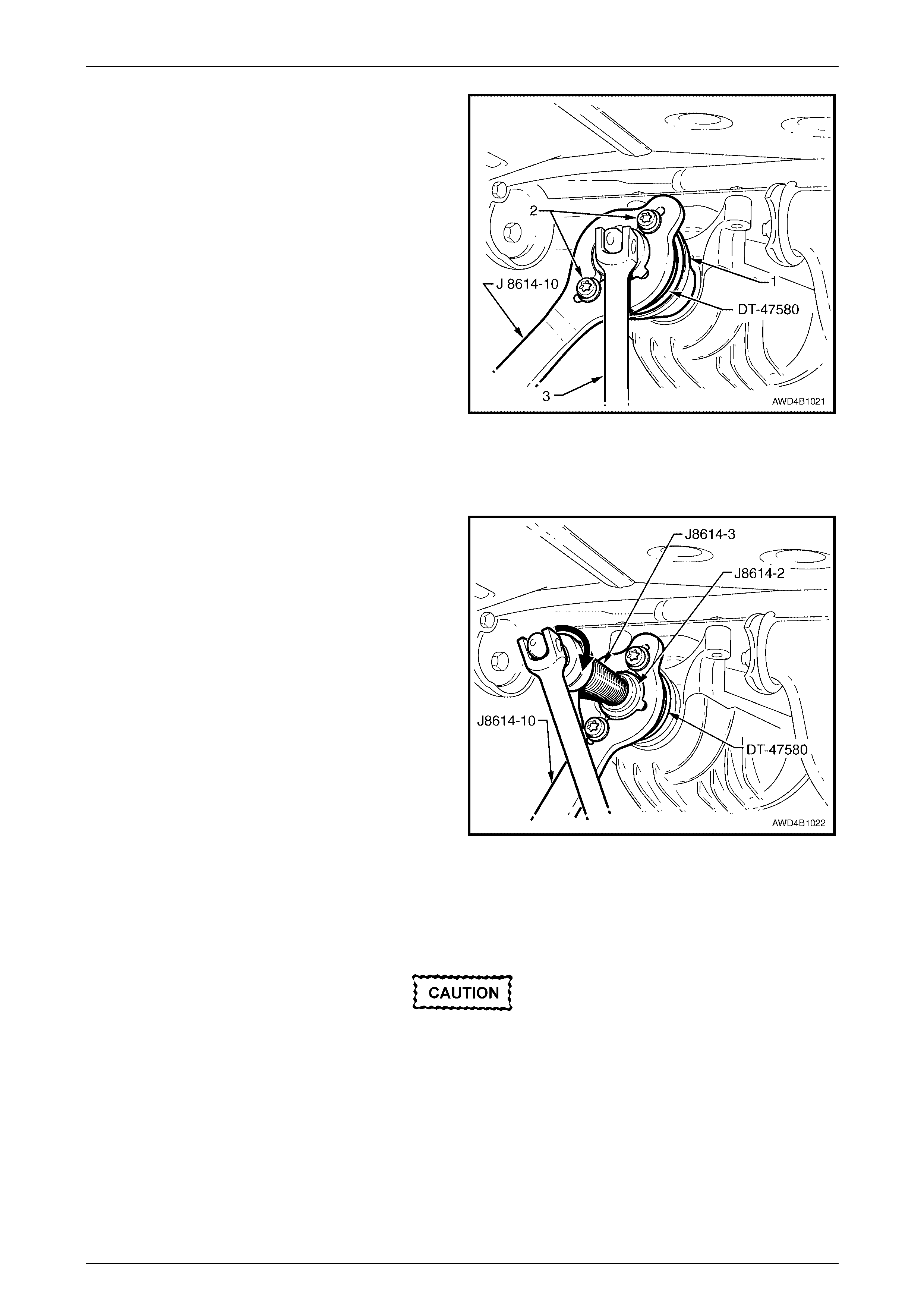
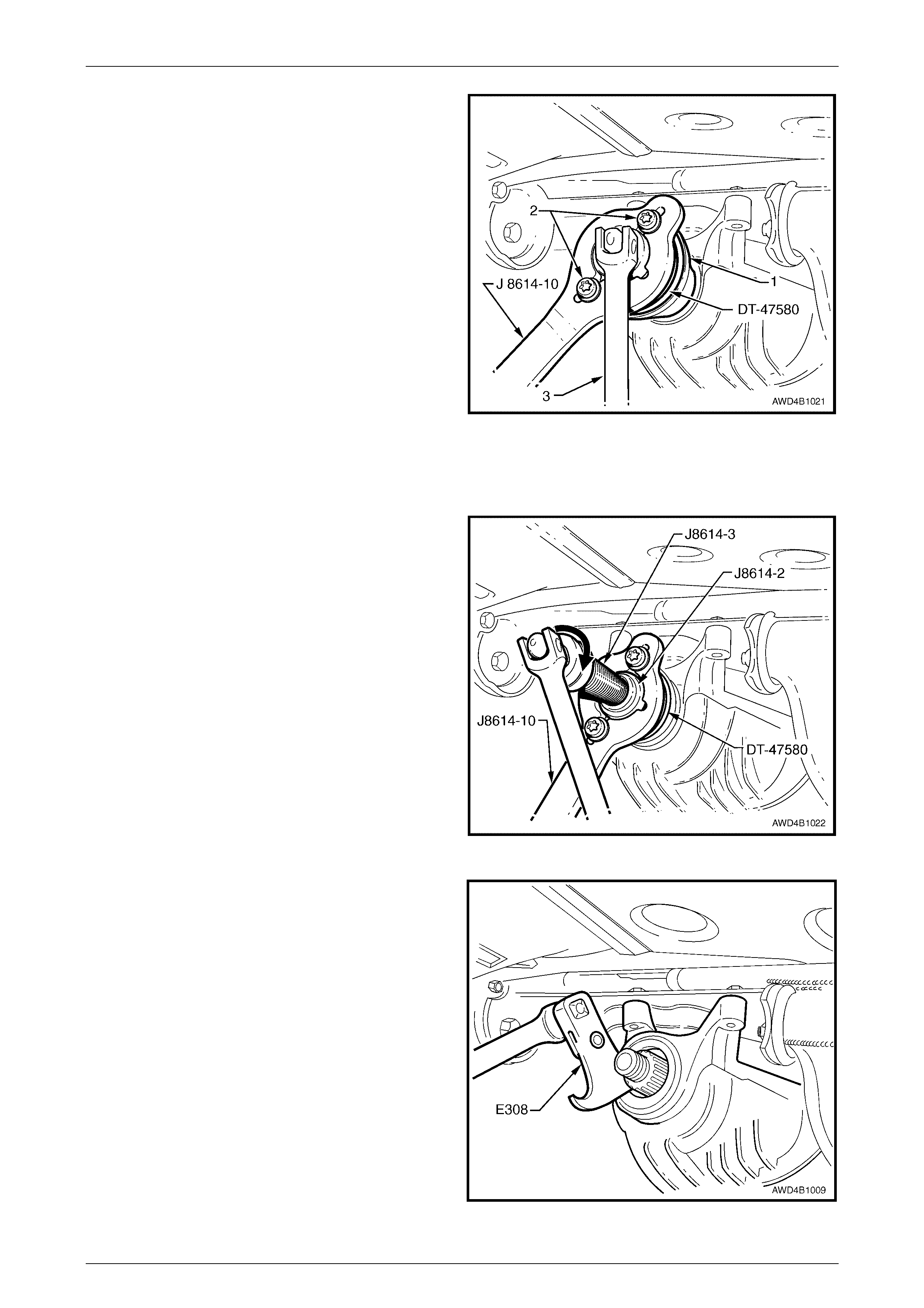
5 Install packing flange DT-47580 into the pinion flange
recess, aligning the holes with those in the pinion
flange.
6 Using two of the propeller shaft constant velocity joint
bolts (2) with flat washers, secure the holding bar, Tool
No. J8614-10 (part of Tool No. J 8614-O1) to the
pinion flange (1). The central recesses in the holding
tool should face inw ard.
7 While anchoring Tool No. J8614-10, loosen then
remove the pinion flange retaining nut, using a
commercially available, 30 mm deep socket and
socket bar (3).
NOTE
A suitable length of pipe installed over the end of
the socket bar will reduce the effort required to
loosen the pinion flange nut.
Figure 4B1 – 24
Rear Final Drive & Driveshafts Page 4B1–17
Page 4B1–17
8 Place drain tray beneath differential carrier.
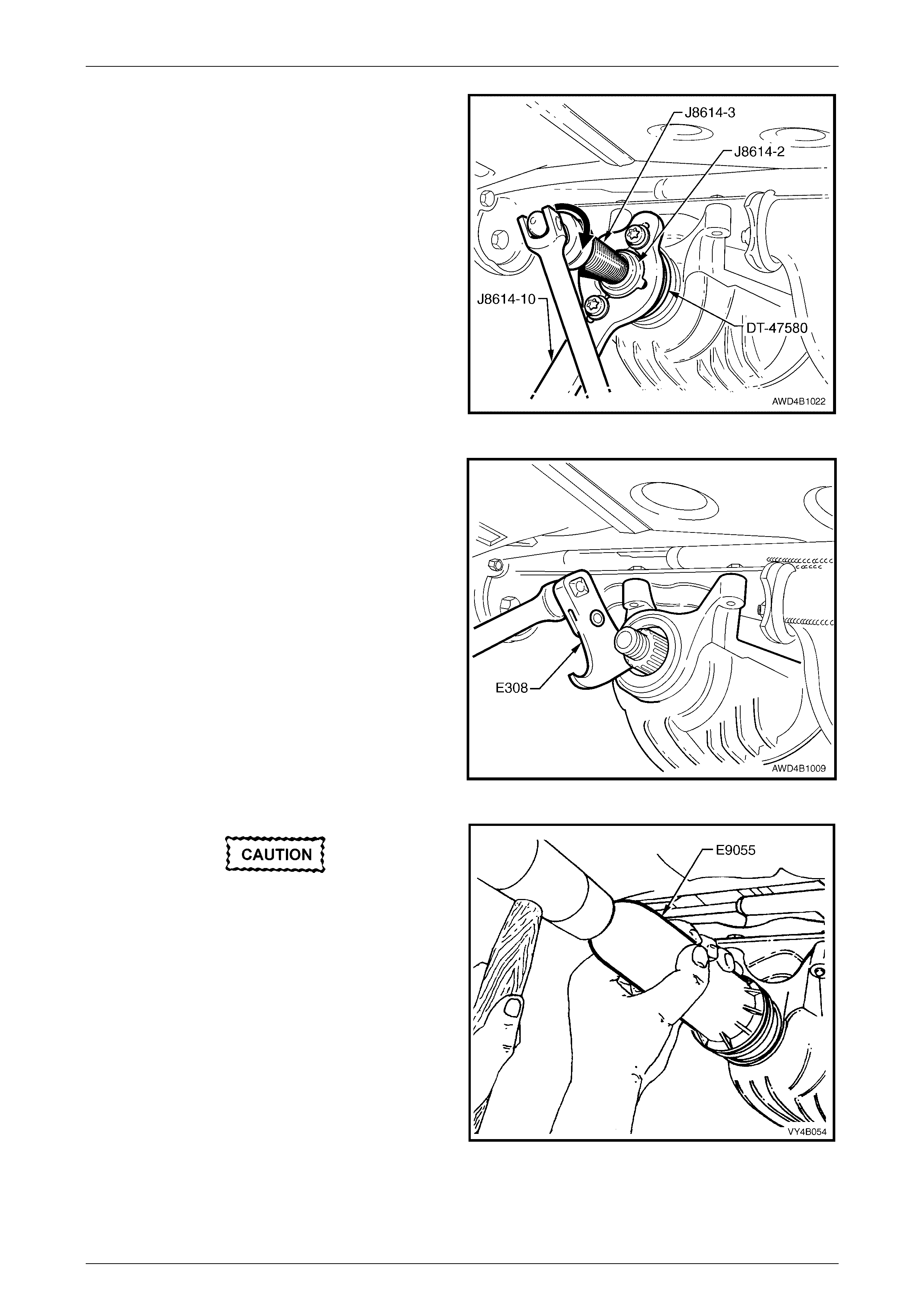
9 With Tool Nos J8614-10 and DT-47580 still installed,
thread the forcing screw, Tool No. J8614-3, into the
adaptor, Tool No. J8614-2. Install this sub-assembly
into holder, Tool No. J8614-10, then rotate through 45°
to locate in the recesses in J8614-10.
10 While holding J8614-10, use a socket and bar to rotate
the forcing screw J8614-3 in the direction shown, to
remove the pinion flange.
11 Remove the tools from the pinion flange, then carefully
set the pinion flange to one side to avoid damage to
the flanged seal surface.
Figure 4B1 – 25
12 Prise pinion oil seal from carrier bore using Tool No.
E308 or a universal seal removing tool.
Figure 4B1 – 26
When installing a new pinion oil seal, only
install the seal until it is square and flush
with the machined face of the final drive
housing. If installed too deeply then a
premature oil leak could occur.
13 Lubricate the lips and outside diameter of a new pinion
oil seal with the Mobilgrease XHP 222. The recess
between the lips should be approximately 50% filled
with grease. A light coating of grease is also to be
applied to the dirt lip that contacts the pinion flange
slinger.
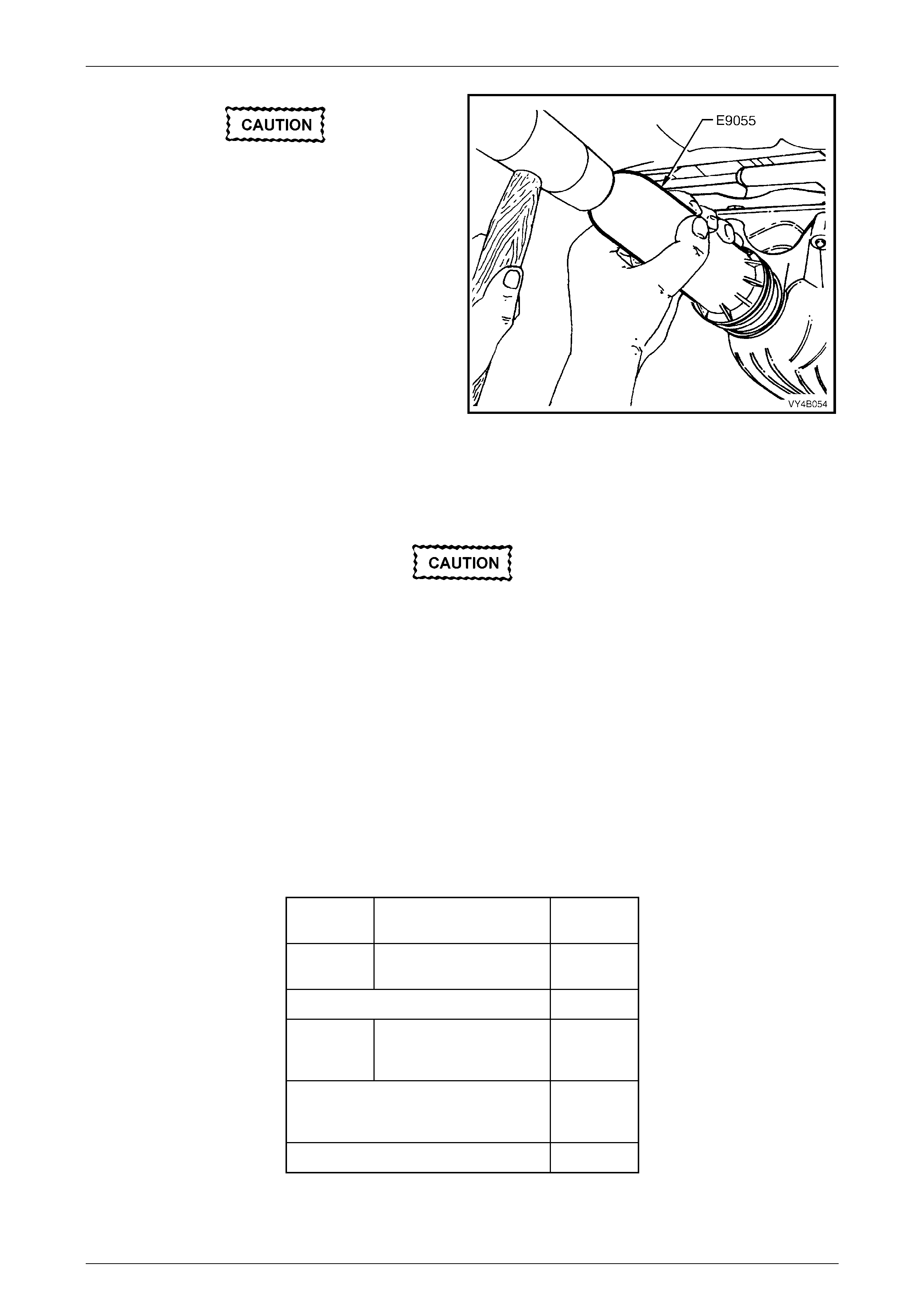
14 Start oil seal into differential carrier housing and drive
seal squarely into position using Tool No. E9055.
15 Ensure that pinion shaft is free from burrs and that
flange oil seal surface is free from damage. Figure 4B1 – 27
16 Clean the threads of the pinion shaft and the flange retaining nut, removing any oil, dirt or grease.
Rear Final Drive & Driveshafts Page 4B1–18
Page 4B1–18
17 Coat splines and seal surface of pinion flange with the recommended final drive lubricant, and install flange onto
pinion shaft splines. Ensure that centre-punch marks made at Step 4, are aligned.
18 Reinstall the packing flange Tool No. DT-47580 and holding tool J 8614-10 to the pinion flange, as detailed in
Steps 5 and 6.
19 Apply a thread locking compound such as Loctite 262 or equivalent, to the cleaned threads of the pinion flange
retaining nut, then reinstall the nut.
20 Tighten the flange retaining nut until all centre-punch marks align. Then carefully tighten the nut to a position not
more than 5° past the aligned setting.
• The pinion flange is an interference fit on
pinion shaft splines and should only be
pulled into place by tightening the
retaining nut. During installation, do not,
under any circumstances, use force or
hammer the flange onto the pinion splines.
• Should the retaining nut be over-tightened
and pre-load exceeded, it will be
necessary to remove the pinion from the
carrier and install a new collapsible
spacer. Under no circumstances must the
retaining nut be backed off to decrease the
pre-load setting.
21 Reinstall propeller shaft, refer to Section 4C1 Propeller Shaft and Universal Joints, in the MY 2004 AWD Wagon
Service Information.
22 If removed previously, reconnect exhaust system, in the reverse to the removal procedure. Refer to
Section 8B Exhaust System, in the MY 2004 AWD Wagon Service Information, for details.
23 Remove safety stands and lower vehicle.
24 Check lubricant level and top up as necessary. Refer to 2.2 Checking Differential Carrier Lubricant Level, in
Section 4B Final Drive and Driveshafts, in the MY 2003 VY and V2 Series Service Information.
25 Start vehicle and check for exhaust leak s.
Rear Final Drive & Driveshafts Page 4B1–19
Page 4B1–19
2.5 Pinion Flange
LT Section No: 05-290
ATTENTION
The following fasteners MUST be replaced when performing these operations:
!
!!
! All removed driveshaft constant velocity joint attaching bolts.
Replace
Using Old Seal
Due to production tolerances in the length of
the pinion flange, it is essential that the
following method be used when installing a
new pinion flange.
1 Using a floor jack under centre of differential carrier, jack up rear of vehicle then place safety stands under trailing
arms.
2 Remove propeller shaft, refer 2.1 Propeller Shaft, in Section 4C1 Rear Propeller Shaft & Universal Joints, in the MY
2004 AWD Wagon Service Information.
3 Remove both driveshafts, refer 2.2 Driveshafts in this Section.
4 Check and record pre-load at pinion flange as follows:
a Fit a pulley (1) to pinion flange, using two
M8 x 1.25 bolts and attach a cord around pulley
and to a spring scale (2).
NOTE
For details of the fabricated pulley, refer
7 Special Tools at end of this Section.
b Start rotation of pulley and whilst in motion
(approximately 50-60 rpm) note and record
reading of spring balance.
NOTE
• This pre-load reading includes pinion
bearings, side bearings, meshing effect of
gear set and pinion oil seal.
• To determine pre-load, multiply reading on
spring balance by radius of pulley.
Example: With a pulley diameter of 152 mm, the radius is
76 mm, = 0.076 m. With a spring balance reading of 25 N,
the pre-load = 0.076 m x 25 N = 1.9 Nm.
5 Remove pulley from pinion flange.
Figure 4B1 – 28
Rear Final Drive & Driveshafts Page 4B1–20
Page 4B1–20
6 Install packing flange, Tool No. DT-47580 into the
pinion flange recess, aligning the holes with those in
the pinion flange.
7 Using two of the propeller shaft constant velocity joint
bolts (2), with flat washers, secure the holding bar,
Tool No. J8614-10 (part of Tool No. J 8614-O1) to the
pinion flange (1). The central recesses in the holding
tool should face inw ard.
8 While anchoring Tool No. J8614-10, loosen the pinion
flange retaining nut, using a commercially available,
30 mm deep socket and socket bar (3), until end play
can be felt in the pinion shaft.
NOTE
A suitable length of pipe installed over the end of
the socket bar will reduce the effort required to
loosen the pinion flange nut.
9 Check the oil seal and differential side bearing pre-
load using the spring scale and pulley, as detailed in
steps 4a and 4b. Record oil seal and side bearing pre-
load for later use.
Figure 4B1 – 29
10 Place drain tray beneath differential carrier.
11 With Tool Nos J8614-10 and DT-47580 still installed,
thread the forcing screw, Tool No. J8614-3, into the
adaptor, Tool No. J8614-2. Install this sub-assembly
into holding bar, Tool No. J8614-10, then rotate
through 45° to locate in the recesses in J8614-10.
12 While holding J8614-10, use a socket and bar to rotate
the forcing screw J8614-3 in the direction shown, to
remove the pinion flange.
13 Remove the tools from the pinion flange, then carefully
set the pinion flange to one side to avoid damage to
the flanged seal surface.
Figure 4B1 – 30
14 Ensure that pinion shaft thread is free from thread sealant, burrs, oil, dirt or grease, then coat splines and seal
surface of a new pinion flange with the recommended final drive lubricant.
15 Install the new pinion flange and a new retaining nut.
The new pinion flange will be an interference
fit on the pinion shaft splines and should only
be pulled into place by tightening the
retaining nut. During installation, do not,
under any circumstances use force or
hammer the flange onto the pinion splines.
16 Tighten flange retaining nut gradually until pinion shaft end play is reduced to approximately 0.50 mm.
17 Attach pulley to the new pinion flange and using spring balance, check pre-load. Continue tightening nut while
alternatively turning pinion to seat bearings, until the pre-load figure recorded previously (Step 4b) is reached.
Further increase this original pre-load reading by 0.5 Nm.
Rear Final Drive & Driveshafts Page 4B1–21
Page 4B1–21
18 Rotate the pinion an extra 30 – 40 turns and re-check the preload to ensure that no change has occurred.
Should the retaining nut be over-tightened
and the pre-load exceeded, it will be
necessary to remove the differential carrier
assembly and install a new collapsible
spacer. Under no circumstances must the
retaining nut be backed off to decrease the
pre-load setting.
19 Reinstall driveshafts, refer to 2.2 Driveshaft Assembly in this Section.
20 Reinstall propeller shaft, refer to Section 4C1 Rear Propeller Shaft & Universal Joints, in the MY 2004 AWD Wagon
Service Information.
21 If removed previously, reconnect exhaust system, in reverse to the removal procedure. Refer to
Section 8B Exhaust System, in the MY 2004 AWD Wagon Service Information, Section , for details.
22 Remove safety stands and lower vehicle to the ground.
23 Check lubricant level and top up as necessary with the recommended lubricant, refer to 2.2 Checking Differential
Carrier Lubric ant Level, in Section 4B Final Drive and Driveshafts, in the MY 2003 VY and V2 Series Service
Information.
24 Start vehicle and check for exhaust leak s.
Using New Oil Seal
1 Using a floor jack under centre of differential carrier, raise the rear of vehicle then place safety stands under trailing
arms.
2 Remove propeller shaft, refer to Section 4C1 Rear Propeller Shaft & Universal Joints, in the MY 2004 AWD Wagon
Service Information.
3 Remove both driveshafts, refer to 2.2 Driveshaft Assembly in this Section.
4 Check and record pre-load at pinion flange as follows:
a Fit a pulley (1) to pinion flange, using two
M8 x 1.25 bolts and attach a cord around pulley
and to a spring balance (2).
NOTE
For fabricated pulley details, refer to 7 Special
Tools at end of this Section.
b Start rotation of pulley and whilst in motion
(approximately 50-60 rpm), note and record the
spring balance reading.
NOTES
• This pre-load reading includes pinion
bearings, side bearings, meshing effect of
gear set and pinion oil seal.
• To determine pre-load, multiply reading on
spring balance by radius of pulley.
Figure 4B1 – 31
Example: With a pulley diameter of 152 mm, the radius is 76 mm which equals 0.076 m. With a spring balance reading
of 25 N, the pre-load equals 0.076 m x 26 N = 1.9 Nm.
5 Remove pulley from pinion flange.
Rear Final Drive & Driveshafts Page 4B1–22
Page 4B1–22
6 Install packing flange, Tool No. DT-47580 into the
pinion flange recess, aligning the holes with those in
the pinion flange.
7 Using two of the propeller shaft constant velocity joint
bolts (2), with flat washers, secure the holding bar,
Tool No. J8614-10 (part of Tool No. J 8614-O1) to the
pinion flange (1). The central recesses in the holding
tool should face inw ard.
8 While anchoring Tool No. J8614-10, loosen the pinion
flange retaining nut, using a commercially available,
30 mm deep socket and socket bar (3), until end play
can be felt in the pinion shaft.
NOTE
A suitable length of pipe installed over the end of
the socket bar will reduce the effort required to
loosen the pinion flange nut.
9 Check the oil seal and differential side bearing pre-
load using the spring scale and pulley, as detailed in
steps 4a and 4b. Record oil seal and side bearing pre-
load for later use.
Figure 4B1 – 32
10 Place drain tray beneath differential carrier.
11 With Tool Nos J8614-10 and DT-47580 still installed,
thread the forcing screw, Tool No. J8614-3, into the
adaptor, Tool No. J8614-2. Install this sub-assembly
into holder, Tool No. J8614-10, then rotate through 45°
to locate in the recesses in J8614-10.
12 While holding J8614-10, use a socket and bar to rotate
the forcing screw J8614-3 in the direction shown, to
remove the pinion flange.
13 Remove the tools from the pinion flange, then carefully
set the pinion flange to one side.
Figure 4B1 – 33
14 Prise pinion oil seal from carrier bore using Tool No.
E308 or a commercially available, universal seal
removing tool.
Figure 4B1 – 34
Rear Final Drive & Driveshafts Page 4B1–23
Page 4B1–23
When installing a new pinion oil seal, only
install the seal until it is flush with the
machined face of the final drive housing. If
installed too deeply then a premature oil leak
could occur.
15 Lubricate the lips and outside diameter of a new pinion
oil seal with the Mobilgrease XHP 222. The recess
between the lips should be approximately 50% filled
with grease. A light coating of grease is also to be
applied to the dirt lip that contacts the pinion flange
slinger.
16 Start oil seal into differential carrier housing and drive
seal squarely into position using Tool No. E9055.
17 Ensure that pinion shaft is free from burrs, then clean
the threads of the pinion shaft, removing any thread
sealant, oil, dirt or grease. Figure 4B1 – 35
18 Coat splines and seal surface of pinion flange with the recommended final drive lubricant, then reinstall flange to
the pinion shaft splines.
19 Install a new flange retaining nut, then tighten to draw the pinion flange onto the pinion shaft splines.
The new pinion flange will be an interference
fit on the pinion shaft splines and should only
be pulled into place by tightening the
retaining nut. During installation Do not,
under any circumstances use force or
hammer the flange onto the pinion splines.
20 Continue to tighten the flange retaining nut gradually until pinion shaft end play is reduced to approximately
0.5 mm.
21 Check new oil seal and differential assembly pre-load using spring balance as previously outlined in steps 4a and
4b. Record pre-load for reassembly reference.
22 The pre-load reading for the final drive assembly obtained in step 9, is subtracted from the pre-load reading
obtained in step 21. The difference between these figures represents extra lip tension of new seal expressed as a
Nm pre-load figure. The difference between the pre-load readings obtained in steps 9 and 21 must be added to
pre-load reading obtained in step 4b to obtain a total pre-load reading.
Theoretical Example
Step 21 New oil seal and side
bearing pre-load setting 1.47 Nm
Step 9 Old seal and side bearing
pre-load reading 1.02 Nm
Subtract Step 9 from Step 21 0.45 Nm
Step 4b Complete differential
assembly pre-load
reading 1.47 Nm
The pre-load reading combination will
be the s um of: -
1.47 Nm
plus
0.45 Nm
Which gives a total pre-load reading of:- 1.92 Nm
23 Continue tightening retaining nut while alternately turning pinion to seat bearings until total pre-load figure obtained
in step 22 is achieved, then increase this pre-load reading by 0.11 – 0.34 Nm. Further rotate pinion an extra 30-40
turns and recheck pre-load to ensure that no change has occurred.
Rear Final Drive & Driveshafts Page 4B1–24
Page 4B1–24
Should the retaining nut be over-tightened
and the pre-load exceeded, it will be
necessary to remove the differential carrier
assembly and install a new collapsible
spacer. Under no circumstances must the
retaining nut be backed off to decrease the
pre-load setting.
NOTE
It must be realised that the pre-load readings in
the example are only theoretical. In practice, the
figures could differ greatly, so the readings
obtained when performing the actual operations,
are the ones to use.
24 Reinstall driveshafts, refer to 2.2 Driveshaft Assembly in this Section.
25 Reinstall propeller shaft, refer to Section 4C1 Rear Propeller Shaft & Universal Joints, in the MY 2004 AWD Wagon
Service Information,.
26 If removed previously, reconnect exhaust system, in the reverse to the removal procedure. Refer to
Section 8B Exhaust System, in the MY 2004 AWD Wagon Service Information, for details.
27 Remove safety stands and lower vehicle.
28 Check lubricant level and top up as necessary, refer to 2.2 Checking Differential Carrier Lubricant Level,
Section 4B Final Drive and Driveshafts, in the MY 2003 VY and V2 Series Service Information.
29 Start vehicle and check for exhaust leak s.
Rear Final Drive & Driveshafts Page 4B1–25
Page 4B1–25
3 Major Service Operations
3.1 Trailing Arm Trunnion Flange, Trunnion
Assembly and/or Wheel Bearing
LT Section No: 05-290
ATTENTION
The following fasteners MUST be replaced when performing these operations:
!
!!
! Collar nut to trunnion assembly.
NOTES
• With the revised design of the trailing arm for
this vehicle, to replace any of the subject
items, removal of the trailing arm assembly
from the vehicle is necessary. Refer to
Section 4A Rear Suspension in the MY 2004
AWD Wagon Service Information for the
removal and disassembly processes, with the
trailing arm rem oved from the vehicle.
• The rear wheel bearing should only be
removed if it is faulty, or if the trunnion
assembly is to be removed.
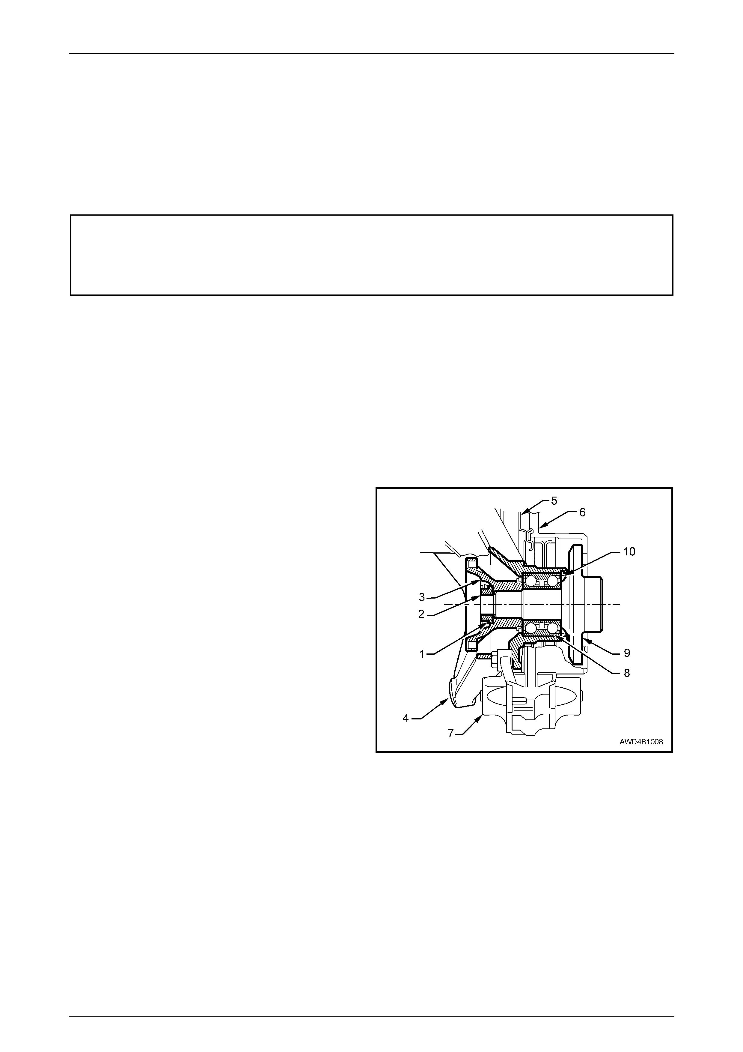
Legend
1 Collar Nut Lock Plate
2 Collar Nut
3 Trunnion Flange
4 Trailing Arm
5 Brake Backing Plate
6 Brake Disc
7 Brake Caliper
8 Rear Wheel Bearing
9 Trunnion Assembly
10 Rear Wheel Bearing Retaining Ring
Figure 4B1 – 36
Rear Final Drive & Driveshafts Page 4B1–26
Page 4B1–26
3.2 Rear Final Drive Assembly
LT Section No: 05-290-1
ATTENTION
The following fasteners MUST be replaced when performing these operations:
!
!!
! Final drive assembly to crossmember attaching bolts.
!
!!
! Rear mount to differential carrier rear cover attaching bolts.
!
!!
! Rear mount to vehicle underbody attaching bolts.
!
!!
! Rear driveshaft constant velocity joint attaching bolts.
!
!!
! Rear crossmember front mounting bolt
!
!!
! Rear crossmember front mounting brace to underbody bolt.
The following fasteners MUST be at curb height before final tightening:
"
""
" Rear shock absorber to trailing arm bolt.
Whenever any component that forms part of
the ABS is disturbed during Service
Operations, it is vital that the complete ABS
system be checked, using the recommended
procedure. Refer to Section 5B ABS-TC, in
DIAGNOSIS, ABS FUNCTION CHECK in the
MY 2004 AWD Wagon Service Information.
Before disturbing the rear suspension
crossmember mounting bolts, an alignment
procedure is required on reinstallation and a
special tool is required for this purpose. If this
tool is not available, then the crossmember
cannot be correctly aligned and steering
and/or handling abnormalities will result.
NOTE
For this service operation, new intermediate
muffler support retainers must be used on
reassembly.
Remove
1 Raise the vehicle and support in a safe manner. Refer to Section 0A General Information, in the MY 2004 AWD
Wagon Service In formation, for loca tion of jacking and s upport points.
2 Remove the decorative wheel nut caps and mark relationship of the wheels to the hub, using a felt tipped pen or
similar.
3 Loosen, then remove the road wheel attaching nuts, working in a 'star' pattern. Refer to Road Wheel Requirements,
in 2.1 General Information, in this Section. Remove the road wheel.

Rear Final Drive & Driveshafts Page 4B1–27
Page 4B1–27
NOTE
Steps 2 and 3 are necessary to maintain part
relationships and to avoid brake rotor distortion
and the creation of brake shudder, after the
vehicle is placed back in service.
4 To provide access to the propeller shaft fasteners, it is recommended that the exhaust system is removed, from the
rear of the catalytic conv erters , rearward. Refer to Section 8B Exhaust System in the MY 2004 AWD Wagon
Service Information.
5 Remove propeller shaft, refer to Section 4C1 Rear Propeller Shaft & Universal Joints, in the MY 2004 AWD Wagon
Service Information.
6 Set park brake in fully released position, then release
each of the underbody to park brake cable retaining
clips (1) and free cables (2).
Figure 4B1 – 37
7 Remove park brake outer cable retaining bracket bolt
(underbody bracket and bolt are not shown) from the
vehicle underbody.
8 Pull each park brake inner cable forward and up, (1)
out of the cable retainer to release each cable.
9 Pull the outer cable rearward (2) to remo ve from the
underbody retainer.
Figure 4B1 – 38
10 Disconnect brake pipe (3) from brake hose (4) at
trailing arm bracket (2) and remove the brake hose
retaining clip (1) .
Plug the open ends of both pipes and hoses to prevent
unnecessary fluid lo ss and/ or dirt entry .
11 Repeat for the other side.
Figure 4B1 – 39
Rear Final Drive & Driveshafts Page 4B1–28
Page 4B1–28
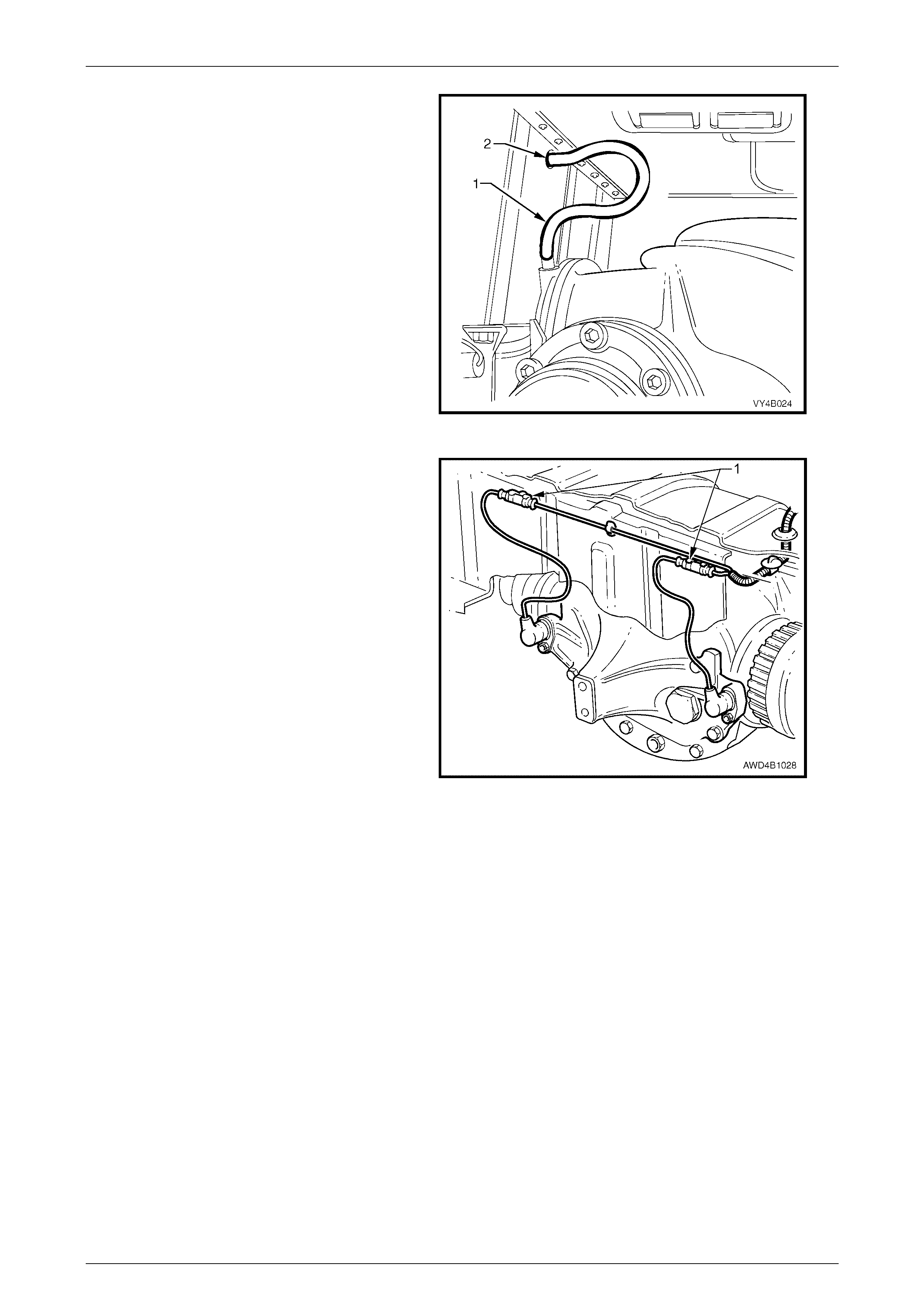
12 Pull out differential carrier breather hose (1) from
vehicle underbody crossmember hole (2).
Figure 4B1 – 40
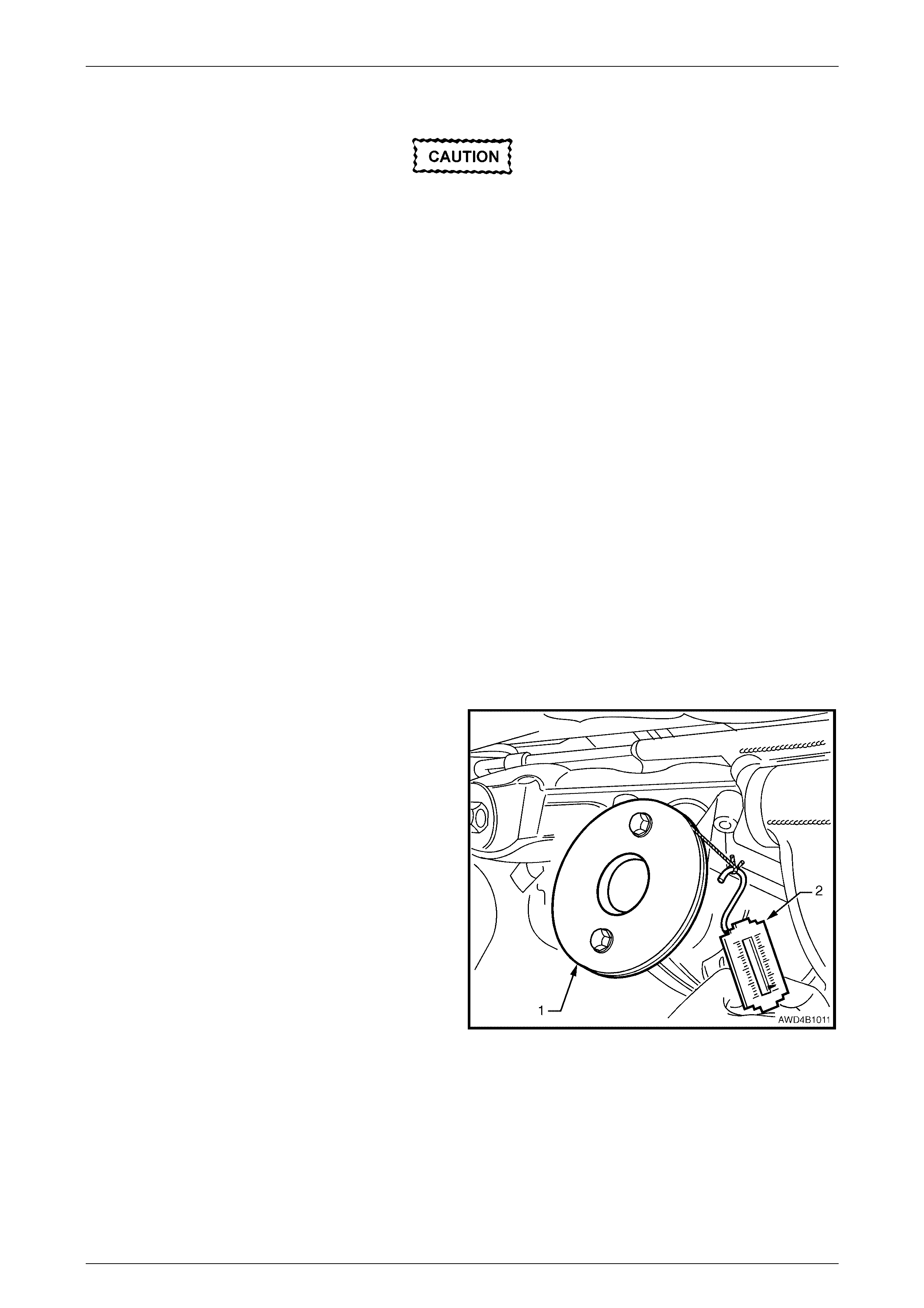
13 Pull both ABS-TC wheel speed sensor lead
connect ors from the under body retaining clips (1).
Separate the sensor connectors from the body
harness connectors by levering with a
screwdriver.
Figure 4B1 – 41
Rear Final Drive & Driveshafts Page 4B1–29
Page 4B1–29
Damage to the driveshaft constant velocity
joint boot caps will occur if the shock
absorber is disconnected from the trailing
arm before the trailing arm is raised.
14 Position floor jack with a block of wood under trailing
arm. Raise jack slightly to take spring load off trailing
arm.
If automatic level ride suspension is fitted to
the vehicle, there are specific procedures
relating to the system pressure and the
removal of the rear shock absorbers. Refer to
Section 4A Rear Suspension, in the MY 2004
AWD Wagon Service Information.
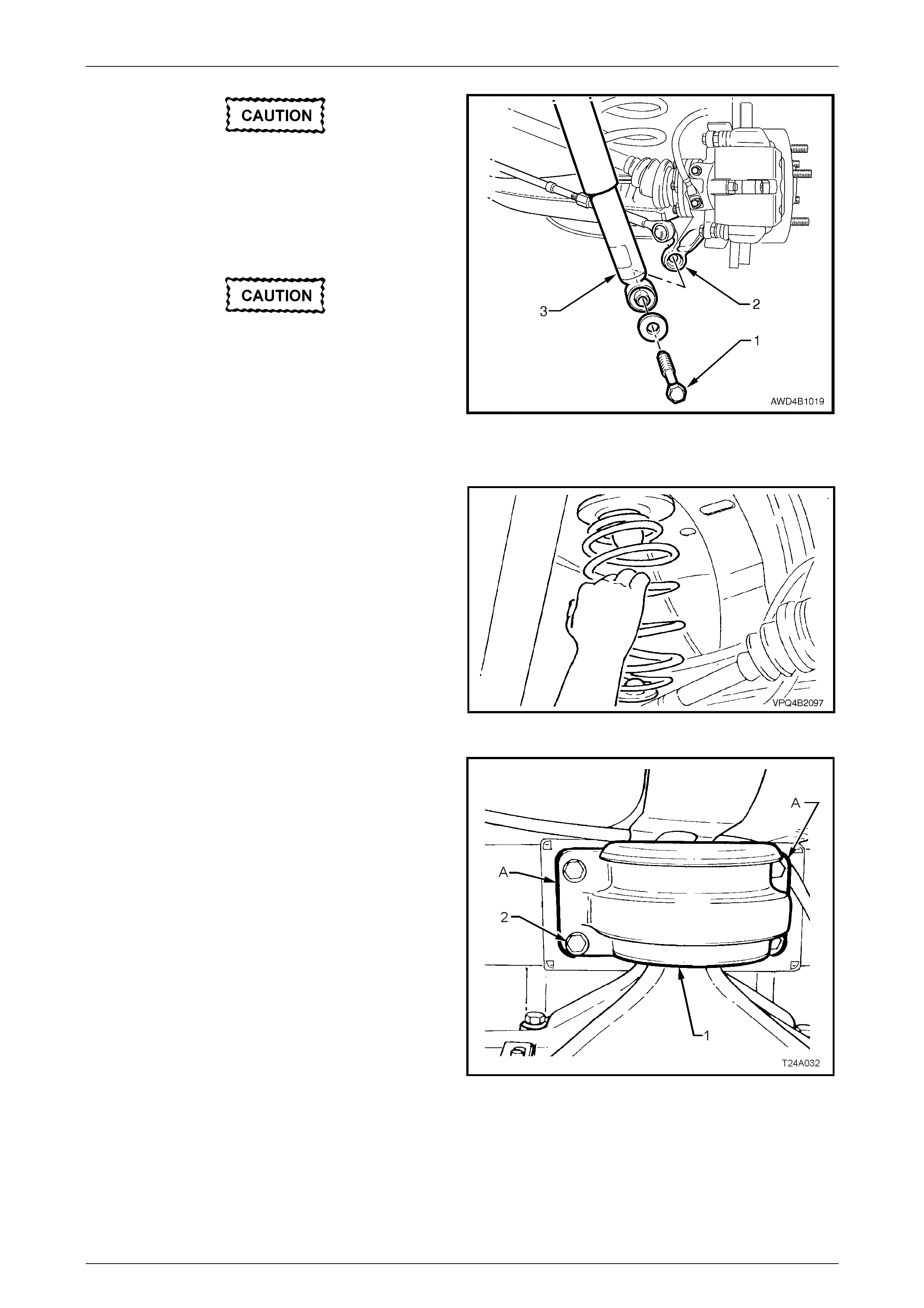
15 Disconnect rear shock absorber lower mounting bolt
(1) from trailing arm (2), and pull lower end of shock
absorber (3) from trailing arm (2).
Figure 4B1 – 42
16 Remove rear springs and insulators from vehicle
underbody and trailing arms.
17 Raise differential carrier and rear crossmember on
floor jack until rear mount cont acts underbo dy .
Figure 4B1 – 43
18 Using a scriber, mark rear mount (1) to vehicle under
body location (A). This will assist in rear crossmember
alignment on reinstallation.
19 Support weight of differential carrier with floor jack.
Figure 4B1 – 44
Rear Final Drive & Driveshafts Page 4B1–30
Page 4B1–30
20 Remove rear mount (1) to vehicle underbody attaching
bolts (2) and discard removed bolts. Lower differential
carrier, spacer (3) and rear crossmember assembly by
at least 60 mm.
Figure 4B1 – 45
21 Use a floor jack and block of wood to support
differential carrier and crossmember assembly.
22 Remove brace to underbody bolts (3) (3 places ) and
crossmember to vehicle underbody attaching bolt (2)
from each side.
23 Remove the braces (1) from the vehicle.
24 With an assistant supporting front end of rear
crossmember, lower assembly on jack and remove
from beneath vehicle.
NOTE
Do not dislodge the snubber bushes (4) fitted to
the centre spigot of each crossmember bushing.
Figure 4B1 – 46
The disconnected driveshaft 'free' end MUST
be supported with tie wire or similar, to keep
constant velocity joint angles to a minimum.
Excessive angles and/or dropping the 'free'
end will cause damage to the boot cap and
the joint itself.
25 Using an 8 mm Allen key socket, remove driveshaft
inner constant velocity joint (1) to inner axle shaft (2)
attaching bolts (3) and plates (4).
Disconnect joints from inner axle shafts.
Figure 4B1 – 47
Rear Final Drive & Driveshafts Page 4B1–31
Page 4B1–31
26 Remove rear crossmember assembly (3) to rear
crossmember (2) attaching bolts (1), remove rear
crossmember assembly from rear final drive assembly
(3) and discard attaching bolts(1).
27 If not carried out in step 20, remove rear mount to rear
cover attaching bolts, remove mount and discard
attaching bolts.
Figure 4B1 – 48
Reinstall
Installation is the reverse of removal procedure except for the following items:
1 If necessary, reinstall rear mount (1) to rear cover
using NEW bolts but leave bolts finger tight at this
stage.
2 Line up mounting holes in rear final drive assembly (2)
and rear crossmember (3). Install NEW attaching bolts
(4) (four places) and tighten to the correct torque
specification.
( ! ) Rear final drive assembly to rear
crossmember attaching bolt
torque specific atio n ..................... 90 Nm, then 40° turn
Figure 4B1 – 49
3 Inspect driveshaft constant velocity joint boots and
covers for damage, replace as necessary. Refer to
2.3 Driveshaft and/or Constant Velocity Joints, in this
Section.
4 To reduce the working angle of the constant velocity
joint the rear trailing arms should still be raised and
supported with a floor jack with a block of wood under
each trailing arm (refer Step 14 of the 'Remove'
procedures).
5 Install NEW driveshaft inner constant velocity joint to
inner axle shaft attaching bolts and tighten to the
correct torque specification.
( ! ) Driveshaft constant velocity
joint attaching bolt
torque specific atio n ..................... 50 Nm, then 70° turn
Figure 4B1 – 50
6 With the aid of two assistants, place the differential carrier and rear crossm ember assembly onto a floor jack.
7 Position assembly under vehicle, raise with the jack and, with the aid of the assistants, guide the crossmember
front mounting points into position.

Rear Final Drive & Driveshafts Page 4B1–32
Page 4B1–32
NOTES
"$ When raising the assembly, take care that the
rear mount does not foul on the fuel tank or
fuel hoses.
"$ During this operation, ensure that trailing
arms are also supported on safety stands, to
keep the driveshafts as near to horizontal as
possible. Otherwise, bruising to the insides of
the constant velocity joint boots will result,
leading to boots splitting and eventually joint
failure, if left unchecked.
8 Reinstall crossmember front mounting braces (1),
attaching bolts (‘3’ – three places) and rear
crossmember, front mounting bolt (2) but do not fully
tighten any of these bolts at this stage.
NOTE
Ensure that each snubber bush (4) is in a
serviceable condition and fitted to the centre
spigot of each crossmember bushing.
Figure 4B1 – 51
9 Lower rear of the final drive assembly to gain access
to the rear mount to cover attaching bolts. Tighten
attaching bolts to the correct torque specification.
At the same time, ensure that mount does not
twist, as the mount to vehicle underbody
mating surface should be parallel to the rear
crossmember, to within 1 mm (distance ‘X’).
( ! ) Rear mount to rear final drive
cover attaching bolt torque specification ............95 Nm
NOTE
Use a spirit level on rear mount to underbody
surface and top surface of crossmember to
ensure that both surfaces are parallel.
Dimension ‘A’ is to be 56.7 mm, measured from
the top of the spacer block.
Figure 4B1 – 52
Rear Final Drive & Driveshafts Page 4B1–33
Page 4B1–33
10 Lower differential carrier and rear crossmember
assembly on floor jack and safety stands. Install rear
springs (1) and the two insulators, (2 and 3).
NOTE
During this operation, the differential carrier and
rear crossmember assembly rear mount must be
lowered at least 60 mm from the vehicle
underbody. Otherwise damage to the driveshaft
constant velocity joint boots will occur.
Figure 4B1 – 53
11 Reinstall shock absorber (3) to the trailing arm (2), fit
washer to the lower mounting bolt, install bolt (1) but
do not fully tighten at this time, as the vehicle must be
at curb weight before final tightening is undertaken.
Figure 4B1 – 54
12 Raise assembly until the spacer (3) and rear mount (1)
contact the vehicle underbody.
13 Align the spacer (3) with marks on underbody, made
on disassembly, then loosely install new attaching
bolts (2) but do not fully tighten at this stage.
Failure to correctly align the rear
crossmember to the centreline of the vehicle
will result in steering problems and uneven
tyre wear!
14 The rear crossmember MUST now be aligned to
the vehicle centreline, using the special tool and
procedure as detailed in Section 1A2 Body
Dimensions, in the MY2003 VY and V2 Series
Service Information.
Figure 4B1 – 55
15 Tighten all crossmember mounting fasteners to the correct torque specification.
Rear Final Drive & Driveshafts Page 4B1–34
Page 4B1–34
( ! ) Rear mount to vehicle
underbody attaching bolt
torque specific atio n ........................35 Nm, plus 60° turn
( ! ) Rear crossmember front
mounting bolt
torque specification ......................125 Nm, then 35° turn
( ! ) Rear crossmember front
mounting brace bolt
torque specific atio n ..............................................75 Nm
16 Install different ial carri er breather hose into vehicle
underbody crossmember hole. Ensure that end of
hose is pushed into hole approximately 25 mm.
Figure 4B1 – 56
17 Reconnect wheel sensor wiring harness connectors.
Reinstall into the retaining clips (1).
18 Reinstall park brake inner cables to the front retainer,
install and secure outer cables in the underbody
retainers, then install the outer cable retaining bracket
bolt to the vehicle underbody.
19 Check and fill differential carrier to correct level with
specified lubricant, refer to 2.2 Checking Differential
Carrier Lubric ant Level, in Section 4B Rear Final Drive
and Driveshafts, in the MY 2003 VY and V2 Series
Service Information.
20 Check park brake adjustment and bleed brake
hydraulic system, refer to Section 5A Service and Park
Braking Systems, in the MY 2 003 VY and V2 Series
Service Information.
21 Reinstall propeller shaft. Refer to Section 4C1 Rear
Propeller Shaft & Universal Joints, in the MY 2004
AWD Wagon Service Information.
22 Reinstall exhaust system, by first installing the front of
the intermediate pipe to the catalytic converters. Use
new gaskets at the converter flanges.
Figure 4B1 – 57
23 While supporting the exhaust system, install the exhaust hanger rubbers to the rear of the intermediate muffler/s
and secure with new retainers.
24 Install rear muffler support rings to the rear of the rear muffler and secure with new retainers.
25 Tighten intermediate exhaust pipe to catalytic converter bolts to the correct torque specification.
Intermediate exhaust pipe to
catalytic conv ert er bolt
torque specific atio n ..............................................45 Nm
Rear Final Drive & Driveshafts Page 4B1–35
Page 4B1–35
26 Check exhaust clearances, Refer to Section 8B Exhaust System, in the MY 2004 AWD Wagon Service Information.
27 Reinstall road wheel/s, aligning the marks made prior to removal and secure with attaching nuts.
28 Remove safety stands and lower vehicle.
29 Bounce the rear of the vehicle several times to settle suspension then, tighten road wheel attaching nuts to correct
torque specification, working in a ‘star’ pattern, refer to Figure 4B1-5, in this Section.
Road wheel attaching nut
torque specific atio n ............................................125 Nm
30 Reinstall wheel nut decorative caps.
31 Tighten lower shock absorber lower mounting bolts to the correct toque specification.
( ! ) Shock absorber lower mounting
bolt torque specification......................................115 Nm
32 Start vehicle and check for exhaust leaks. Repair as necessary.

Rear Final Drive & Driveshafts Page 4B1–36
Page 4B1–36
3.3 Removed Final Drive Assembly
Apart from the fact that the appearance of the pinion flange and the drive pinion is different, the unit repair for the
removed final drive assembly is the same as described for the 3.46:1 ratio assembly without LSD. Refer to 3.3 Removed
Final Drive Assembly, in Section 4B Final Drive and Driveshafts, in the MY 2003 VY and V2 Series Service Information,
for the required procedures.

Rear Final Drive & Driveshafts Page 4B1–37
Page 4B1–37
4 Specifications
NOTE
Only those specifications referred to within this
Section are stated here. For all remaining
specifications, refer to Section 4B Final Drive and
Driveshafts, in the MY2003 VY and V2 Series
Service Information.
GENERAL
Final Drive Assembly............................................................................................... DANA – 80 Series
Drive Type............................................................................................................... Independent Housing
Gear Type ............................................................................................................... Hypoid
Gear Ratio (See ID tag attached to the carrier)....................................................... 3.46:1
No. of Teeth:
Ring Gear.......................................................................................................... 45
Drive Pinion Gear.............................................................................................. 13
LUBRICANT
Final Drive Assembly:
Capacity............................................................................................................. 1.6 litres
Type – Synthetic Hypoid Gear Oil ................................................................... 1.5 litres SAE 80W-140
Plus 'Sturaco' Additive......................................................................... 0.1 litre
FINAL DRIVE PINION GEAR BEARINGS
Bearing Type........................................................................................................... Adjustable Tapered Roller
Bearing Adjustment................................................................................................. Collapsible Spacer
Bearing Pre-Load: Timken Koyo
Dummy pinion - New bearings........................................................................... 1.4 – 2.0 1.5 – 1.9 Nm
Dummy pinion - Used bearings ......................................................................... 0.7 – 1.2 0.7 – 1.2 Nm
New with oil seal................................................................................................ 1.4 – 2.4 1.5 – 2.1 Nm
New without oil seal........................................................................................... 1.4 – 2.0 1.5 – 1.9 Nm
Used with oil seal............................................................................................... 0.7 – 1.2 0.7 – 1.2 Nm
Used without oil seal.......................................................................................... 0.7 – 1.2 0.7 – 1.2 Nm
RUN-OUT SPECIFICATIONS
Trunnion Assembly Hub.......................................................................................... 0.06 mm Total Indicated
Run-out
ABS-TC SENSOR
Air Gap (non-adjustable)......................................................................................... 0.4 – 1.5 mm
SEALANTS
Driveshaft Dust Caps/Shield.................................................................................... RTV 732 Sealant, or
commercial equivalent
Thread Sealant – As Required................................................................................ Loctite 262 or equivalent

Rear Final Drive & Driveshafts Page 4B1–38
Page 4B1–38
6 Torque Wrench Specifications
ATTENTION
!
!!
! Fasteners must be replaced after loosening.
"
""
" Vehicle must be at curb height before final tightening.
#
##
# Fasteners either have micro encapsulated sealant applied or incorporate a mechanical thread lock and
should only be re-used once. If in doubt, replacement is recommended.
NOTE
Only those torque wrench specifications referred
to within this Section are stated here. For all
remaining torque wrench specifications, refer to
Section 4B Final Drive and Driveshafts, in the
MY2003 VY and V2 Series Service Information.
Nm
Brake caliper anchor plat e to traili ng ar m bolt................................................85
" Collar nut to trunnion assembly................................................................300
Drain plug ......................................................................................................28
" Driveshaft constant velocity joint attaching bolt............. 50 Nm, plus 70° turn
Filler plug.......................................................................................................28
" Final drive assembly to crossmember attaching bolt..... 90 Nm, plus 40° turn
Intermediate exhaust pipe to catalytic converter attaching bolt......................45
" Rear crossmember front mounting bolt....................... 125 Nm, plus 35° turn
" Rear crossmember front mounting brace to underbody bolt......................75
Rear disc brake shield to trailing arm. Upper bolt ........................................75
Lower bolt ........................................88
" Rear mount to vehicle underbody attaching bolt........... 35 Nm, plus 60° turn
" Rear mount to differential carrier rear cover attaching bolt ........................95
Road wheel attaching nut............................................................................125
! Shock absorber lower mounting bolt........................................................115
Rear Final Drive & Driveshafts Page 4B1–39
Page 4B1–39
7 Special Tools
NOTE
Only those Special Tools referred to within this
Section are stated here. For all remaining Special
Tools, refer to Section 4B Final Drive and
Driveshafts, in the MY2003 VY and V2 Series
Service Information,
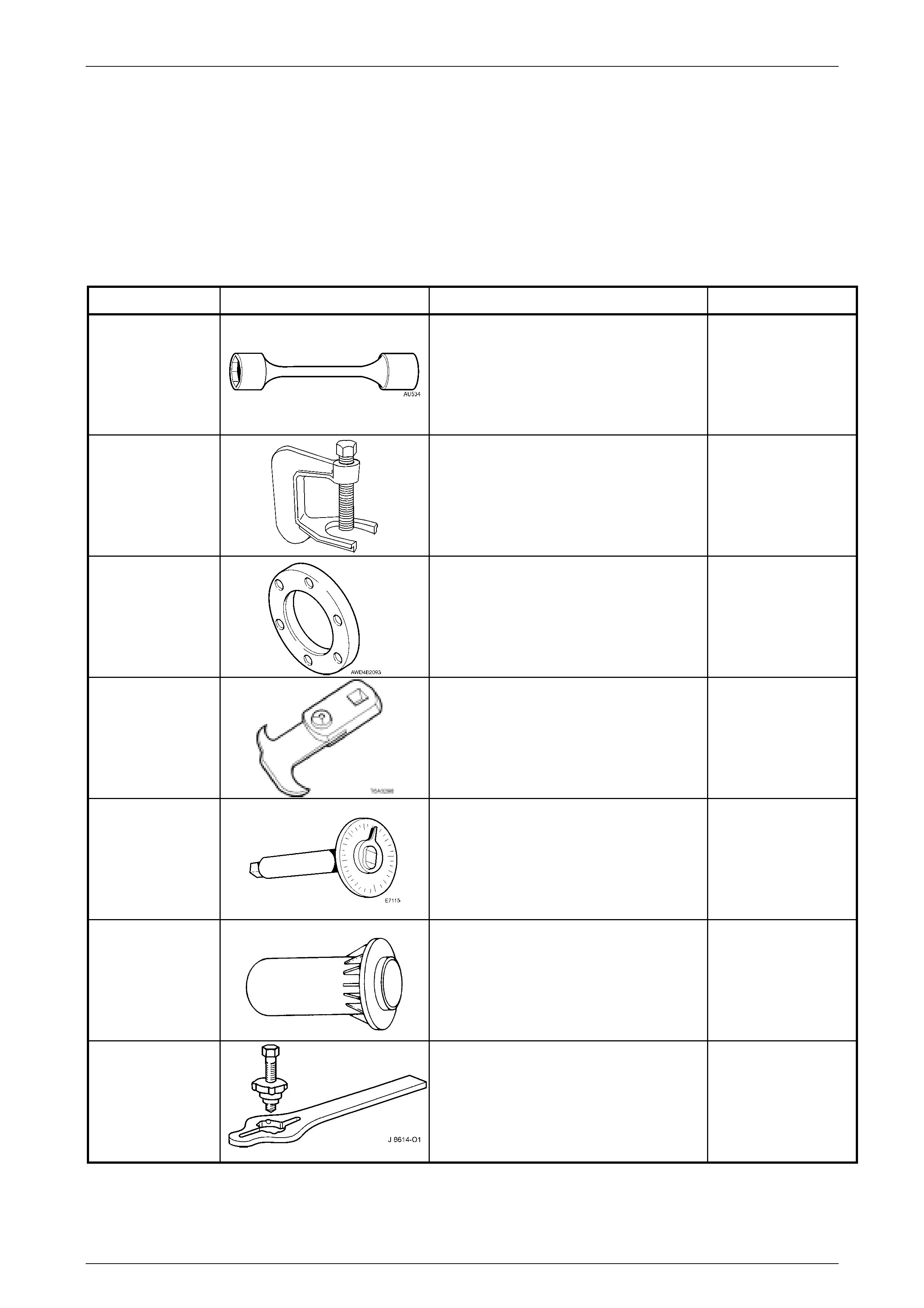
TOOL NUMBER ILLUSTRATION DESCRIPTION CLASSIFICATION
AU 534
Torque Limiting Socket
Used in conjunction with an impact gun to
tighten wheel nuts.
Previously released.
Unique
C4150-C
Press Tool
Used to remove rear wheel studs from the
trunnion flange.
Previously released.
Unique
DT-47580
Packing Flange
Fitted into the pinion flange to act as a
spacer for holding tool J8614-O1
New release
Available
E308 Seal Remover
Used as a universal seal remover. Also
released as 56750.
Previously released.
Available
E7115
Angle Wrench
Used to tighten fasteners when an angle
torque is specif ied .
Also released as BT 8653-A
Previously released.
Unique
E9055
Pinion Oil Seal Installer
Used to install the pinion oil seal.
Also releas ed as 17-010A.
Previously released.
Unique
J 8614-O1 Flange/Pulle y Holding Tool
Includes J 8614-2, J 8614-3 and
J 8614-10
Previously released.
Unique
Rear Final Drive & Driveshafts Page 4B1–40
Page 4B1–40
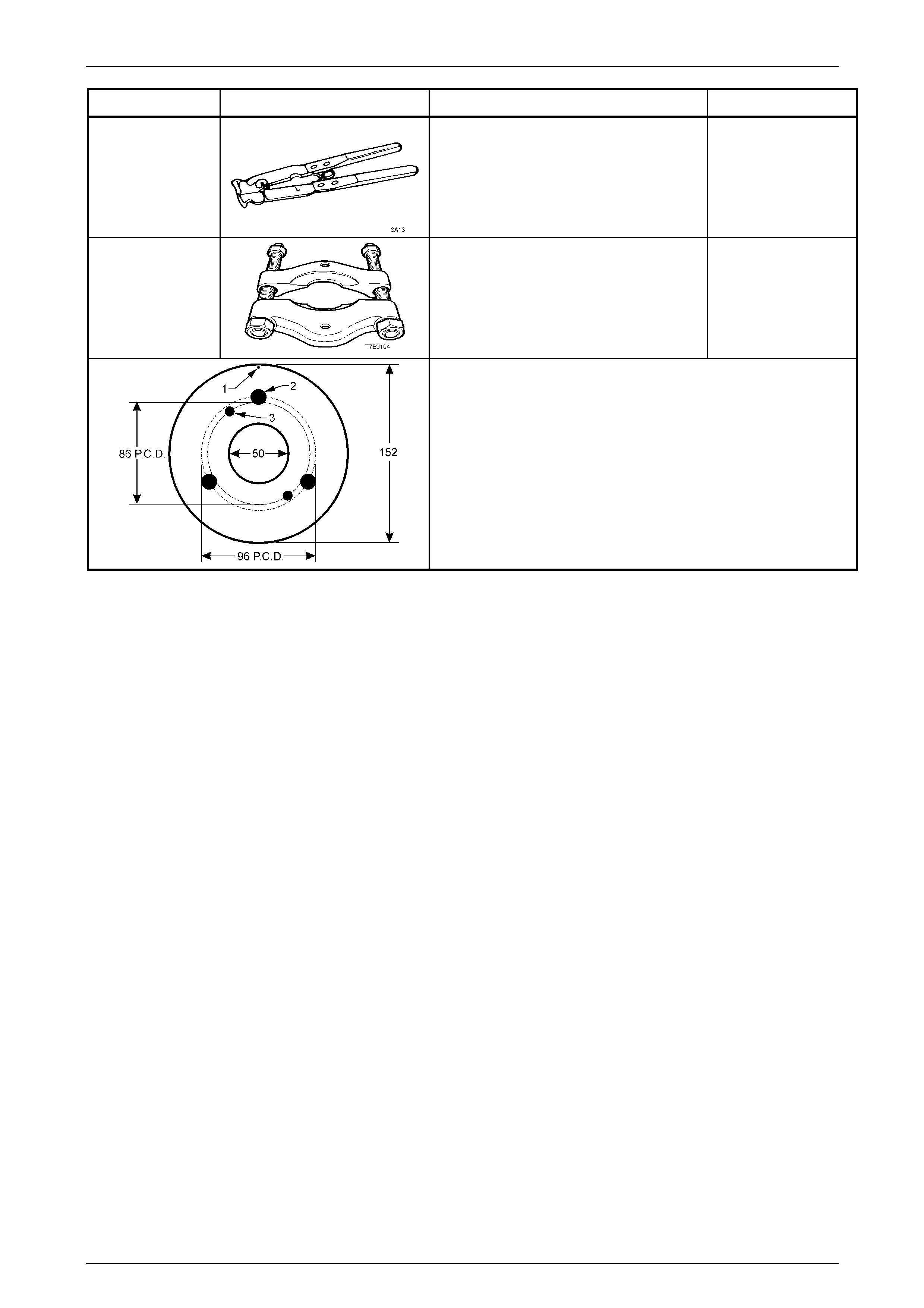
TOOL NUMBER ILLUSTRATION DESCRIPTION CLASSIFICATION
J22610
Clamp Pliers
Used to crimp the drives haft b oot cla mps.
Also releas ed as E1896.
Previously released.
Available
J22912-01
Press Plates
Used in a number of different applications
in removing bearings and other
transmission components when pressing
operations are required.
Previously released.
Unique
Pinion Flange Pulley
Modify the fabricated pulley made up for VY Series vehicles:
1. Made from a 13 mm thick piece of wood.
2. Drill a small hole at '1' and attach a one metre length of
string at this point.
3. Drill two, 8.5 mm holes (3) opposite to each other on a pitch
ci rcle diameter of 86 mm .
4. For application to VY Series final drive pinion flange, drill
three, 13 mm holes (2) on a pitch circle diameter of 96 mm,
120 mm apart.