
Rear Propeller Shaft & Universal Joints Page 4C1–1
Page 4C1–1
Section 4C1
Rear Propeller Shaft & Universal Joints
ATTENTION
Before performing any Service Operation or other procedure described in this Section, refer to Section 00
Warnings, Cautions And Notes for correct workshop practices with regard to safety and/or property damage.
1 General Information............................................................................................................................... 2
2 Service Operations................................................................................................................................3
2.1 Propeller Shaft........................................................................................................................................................3
Remove ...................................................................................................................................................................3
Reinstall ..................................................................................................................................................................4
2.2 Rubber Coupling....................................................................................................................................................6
Replace ...................................................................................................................................................................6
2.3 Centre Constant Velocity Joint.............................................................................................................................7
Remove ...................................................................................................................................................................7
Disassemble .........................................................................................................................................................10
Inspect...................................................................................................................................................................11
Propeller Shaft and Boot...................................................................................................................................11
Constant Velocity Joint.....................................................................................................................................11
Reassemble ..........................................................................................................................................................12
Method 1...........................................................................................................................................................12
Method 2...........................................................................................................................................................12
Reinstall ................................................................................................................................................................14
2.4 Centre Bearing Assembly....................................................................................................................................16
Remove .................................................................................................................................................................16
Reinstall ................................................................................................................................................................17
2.5 Fixed, Rear Constant Velocity Joint ...................................................................................................................19
Remove .................................................................................................................................................................19
Inspect...................................................................................................................................................................20
Propeller Shaft and Boot...................................................................................................................................20
Constant Velocity Joint.....................................................................................................................................21
Reassemble ..........................................................................................................................................................22
Reinstall ................................................................................................................................................................24
3 Specifications....................................................................................................................................... 25
4 Torque Wrench Specifications........................................................................................................... 26
5 Special Tools........................................................................................................................................ 27
Rear Propeller Shaft & Universal Joints Page 4C1–2
Page 4C1–2
1 General Information
The rear propeller shaft assembly fitted to all variants of the MY 2004 AWD Station Wagon models is a two piece tubular
design that incorporates a centre support bearing, with a rubber coupling at the front of the front propeller shaft and a
constant velocity joint at the front and rear of the rear propeller shaft. The front rubber coupling is bolted to the rear
output flange of the transfer case and the rear constant velocity joint is bolted to the rear final drive pinion flange with six
bolts and three locking plates.
The centre support bearing is a fully sealed ball bearing, mounted in a reinforced rubber cup. This centre bearing rubber
cup is supported in a cup guide and attached to a carrier, which in turn, is bolted to the vehicle underbody brace.
Drive is transmitted between the two halves of the propeller shaft through a centre constant velocity joint directly behind
the centre bearing. To allow for slight changes in propeller shaft length that may occur from body twist and torque
reaction, this centre constant velocity joint is a plunge type.
Provided the service information contained in this Section is followed, both constant velocity joints are fully serviceable,
while the centre bearing assembly and the front rubber coupling can be replaced as assemblies only.
The centre bearing is lubricated for life and does not require any periodic lubrication.
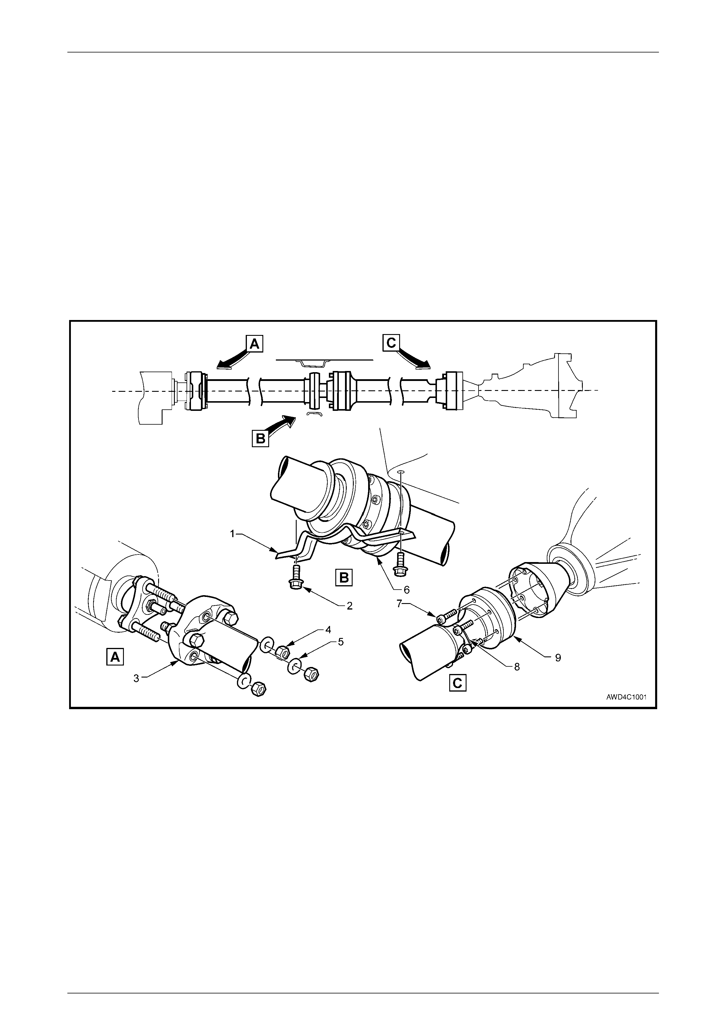
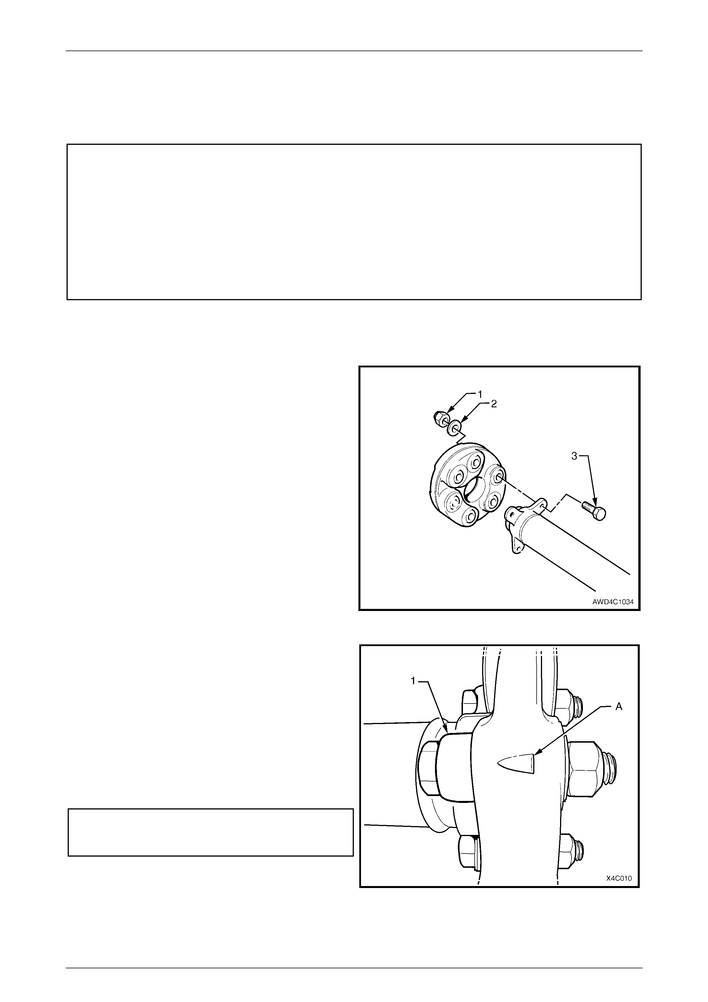
Figure 4C1-1
Legend
1 Centre Bearing Carri er Assem bl y
2 Centre Bearing Carri er Ret ai ning Bolt (2 Places)
3 Front Rubber Coupling
4 Front Coupling Ret aining Nuts (3 Places)
5 Front Coupling Ret aining Nut Washers (3 Plac es)
6 Front Constant Veloci t y Joint (Plunge Type)
7 Rear Constant Vel oci ty Joint Retaining Bolts (6 Places)
8 Locking Plate (3 Places)
9 Rear Constant Vel ocity Joint (Fixed Type)
Rear Propeller Shaft & Universal Joints Page 4C1–3
Page 4C1–3
2 Service Operations
ATTENTION
All fasteners are important attaching parts as they affect the performance of vital components and/or could
result in major repair expense. Where specified in this section, fasteners MUST be replaced w ith parts of the
same part number or an approved equivalent. Do not use fasteners of an inferior quality or substitute design.
Torque values must be used as specified during reassembly to ensure proper retention of all components.
Throughout this section, fastener torque wrench specifications may be accompanied with the following
identification marks:
!
!!
! Fasteners must be replaced after loosening.
"
""
" Vehicle must be at curb height before final tightening.
#
##
# Fasteners either have micro encapsulated sealant applied or incorporate a mechanical thread lock and
should only be re-used once. If in doubt, replacement is recommended.
If one of these identification marks is present alongside a fastener torque wrench specification, the
recommendation regarding that fastener must be adhered to.
2.1 Propeller Shaft
LT Section No. – 05-050
ATTENTION
The following fasteners MUST be replaced when performing these operations:
!
!!
! Rubber coupling to transfer case, rear output flange retaining bolts and nuts.
Fasteners either have micro encapsulated sealant applied or incorporate a mechanical thread lock and
should only be re-used once. If in doubt, replacement is recommended.
#
##
# Propeller shaft centre bearing bracket to the vehicle underbody, attaching bolts.
#
##
# Propeller shaft rear constant velocity joint to pinion flange bolts.
Remove
1 Raise the vehicle and support in a safe manner. Refer to Section 0A General Information in the MY 2004 AWD
Wagon Service Information for location of jacking and support points.
2 To provide access to the propeller shaft fasteners, it is recommended that the dual intermediate exhaust pipe,
intermediate and rear muffler assemblies be removed. For information regarding the removal and installation
procedures for these components, refer to Section 8B Exhaust System in the MY 2004 AWD Wagon Service
Information.
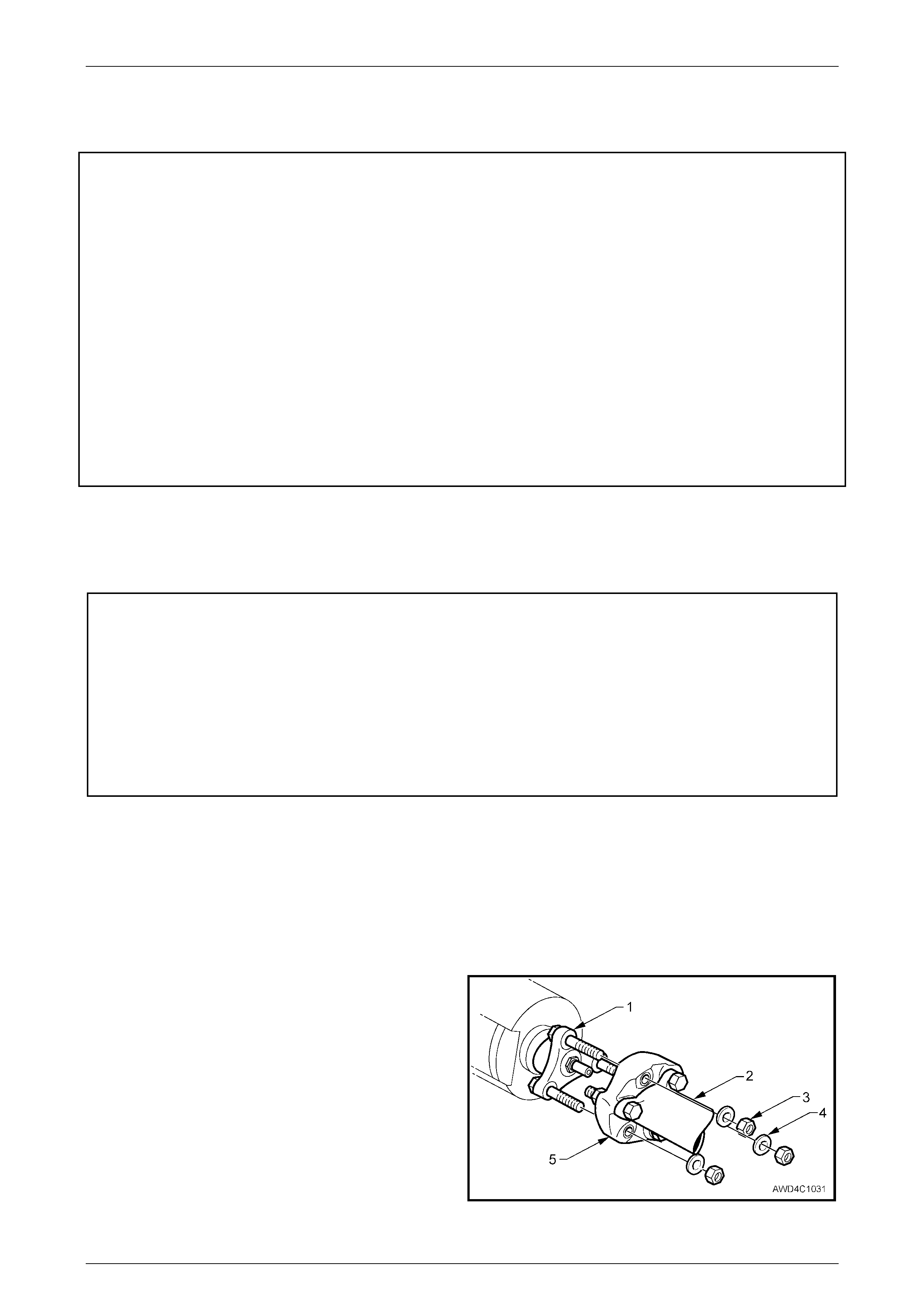
3 Select the Park position with the transmission selector
lever.
4 Loosen then remove the three nuts (3) and washers
(4) securing the front coupling (5) to the transfer case
output flange (1). Discard the removed nuts (3) as they
must be replaced on reassembly.
Figure 4C1 – 2
Rear Propeller Shaft & Universal Joints Page 4C1–4
Page 4C1–4
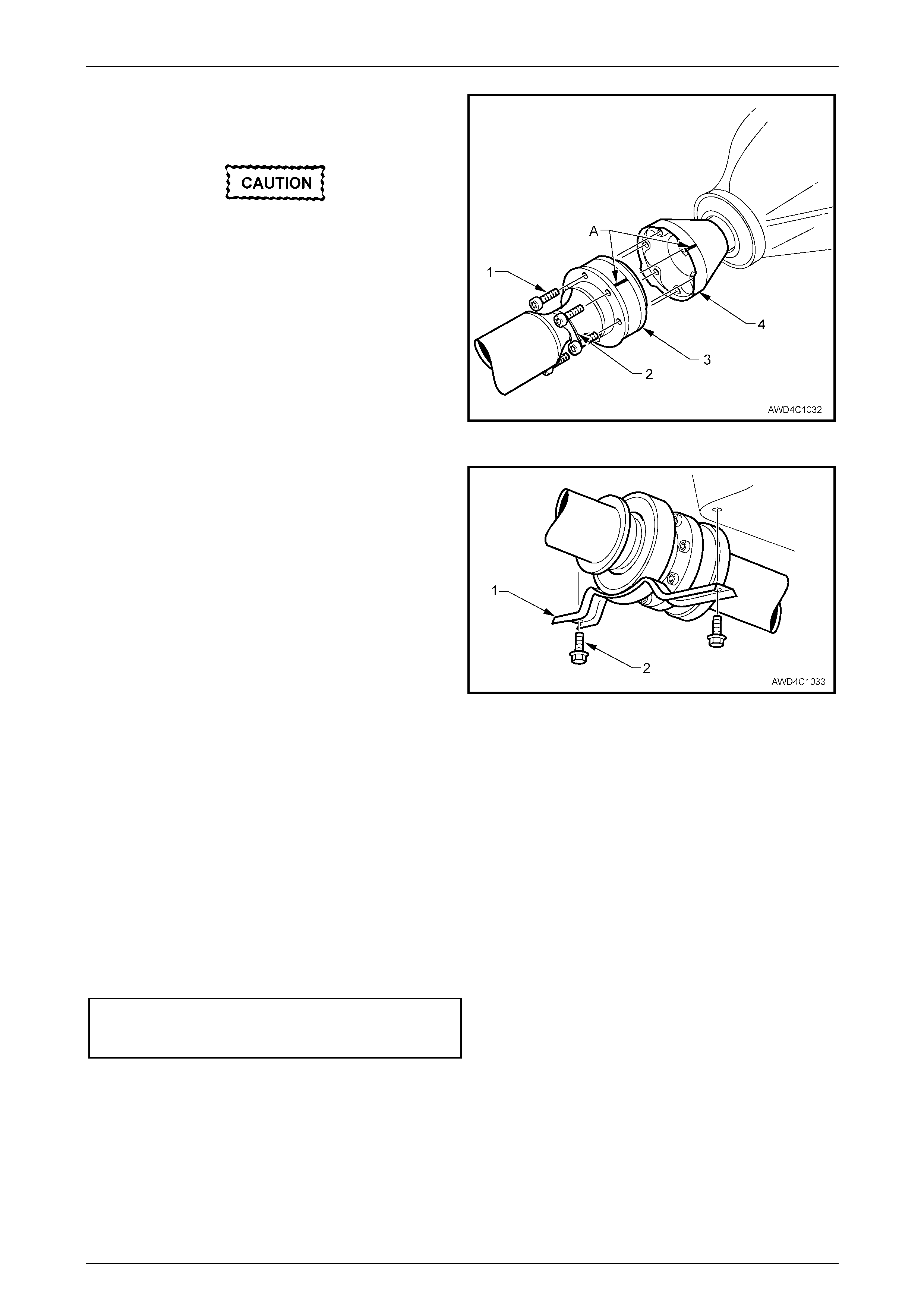
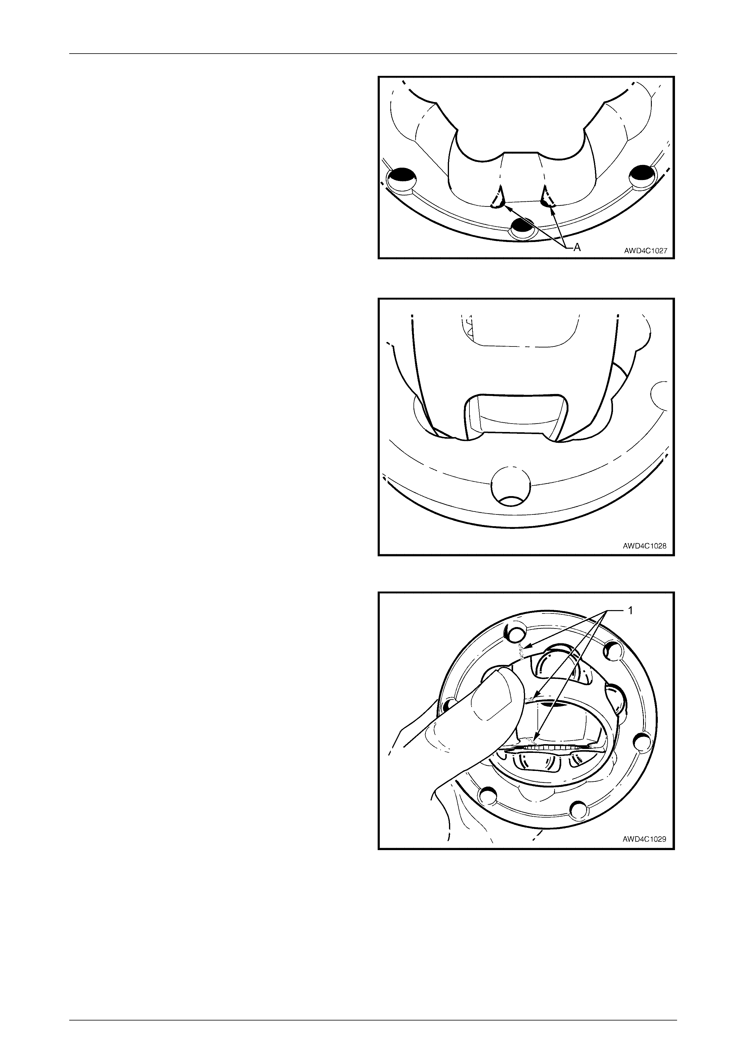
5 To enable the propeller shaft to be installed in the
original position relative to the pinion flange, use a felt
tipped pen or similar (e.g. whiteout) to identify the
relationship of the two components (‘A’).
If all six bolts are removed, the rear of the
propeller shaft must be supported using tie
wire or similar. Do not allow the propeller
shaft to hang, placing undue stress on the
front constant velocity joint.
6 W ith the transmission in the ‘Park’ position and the
park brake firmly applied, loosen the six Torx bit
headed bolts (1), using a T50 Torx bit and suitable
socket equipm ent.
7 Remove five of the six bolts and two locking plates (2)
securing the propeller shaft rear constant velocity joint
(3) to the final drive pinion flange (4). Do not remove
the sixth bolt at this time. Figure 4C1 – 3
8 Remove the two centre bearing carrier (1) to
underbody reinforcement bolts (2), then remove the
heat shield (if fitted) and the centre bearing assembly.
NOTE
The heat shield has not been shown, to clarify
the centre bearing bracket offset.
9 While support ing the cen tre be aring section, remove
the final bolt (and locking plate) from the pinion flange.
10 Slide the propeller shaft assembly forward to
disengage from the final drive pinion flange, then lower
the assembly at the rear, sliding rearward to
disengage the front rubber coupling from the transfer
case output flange studs. Remove the propeller shaft
assembly from the vehicle.
Figure 4C1 – 4
Reinstall
Reinstallation is the reverse of removal procedures, except for the following items:
1 Lubricate the transfer case rear output shaft spigot with a molybdenum disulphide grease such as Molybond GA10
or Shell ML10.
2 Clean the threads of the centre bearing carrier to underbody reinforcement bolts and underbody weld nuts, then
apply a thread sealant such as Loctite 242 or equivalent.
3 Reinstall the front of the propeller shaft assembly first, supporting the centre and rear sections.
4 W hile supporting the rear section, raise the centre bearing assembly and install the bolts and washers to secure to
the underbody reinforcement. Tighten both bolts to the correct torque specification.
( # ) Centre bearing carrier to
underbody reinforcement bolt
torque specific atio n ..............................................22 Nm
5 Slide the propeller shaft assembly forward to allow engagement of the rear constant velocity joint to the final drive
pinion flange, then slide rearward to fully engage.
6 Before reinstalling the attaching bolts and locking plates into the rear constant velocity joint and pinion flange, align
the marks on the pinion flange and rear joint, that were made prior to removal, refer to Figure 4C1-3.
7 Clean the threads of the six, rear constant velocity joint to pinion flange bolts, apply a thread sealant such as
Loctite 242 or equivalent, then reinstall with locking plates and tighten to the correct torque specification, using a
T50 Torx bit and suitable socket equipment.
Rear Propeller Shaft & Universal Joints Page 4C1–5
Page 4C1–5
( # ) Propeller shaft rear constant
velocity joint to pinion flange bolt
torque specific atio n ..............................................35 Nm
8 Reinstall the front rubber coupling to the transfer case rear output flange, using new retaining bolts nuts and
washers, before tightening to the correct torque specification. When reinstalled correctly, the aligning triangular
shapes on the coupling outer surface ‘point’ to the propeller shaft flange. Refer Figure 4C1-6.
( ! ) Rubber coupling to transfer case
output shaft flange retaining nut
torque specific atio n ..............................................78 Nm
9 Reinstall the exhaust system, noting the following;
a. Ensure the catalytic converter flange is clean and free from any gasket material.
b. Install the exhaust system, using a new gasket at the catalytic converter and new hanger retainers for the
muffler supports to the rear crossmember.
c. Tighten all exhaust fasteners to the specified torque.
Intermediate exhaust pipe to
catalytic converter flange bolt
torque specific atio n ..............................................45 Nm
d. Check exhaust clear an ces as detai led in Section 8B EXHAUST SYSTEM in the MY 2004 AWD Wagon
Service Information.
Rear Propeller Shaft & Universal Joints Page 4C1–6
Page 4C1–6
2.2 Rubber Coupling
LT Section No. – 05-050
ATTENTION
The following fasteners MUST be replaced when performing these operations:
!
!!
! Rubber coupling to transfer case, rear output flange retaining bolts and nuts.
Fasteners either have micro encapsulated sealant applied or incorporate a mechanical thread lock and
should only be re-used once. If in doubt, replacement is recommended.
#
##
# Propeller shaft centre bearing bracket to the vehicle underbody, attaching bolts.
#
##
# Propeller shaft rear constant velocity joint to pinion flange bolts.
Replace
1 Remove the propeller shaft. Refer to 2.1 Propeller Shaft in this Section.
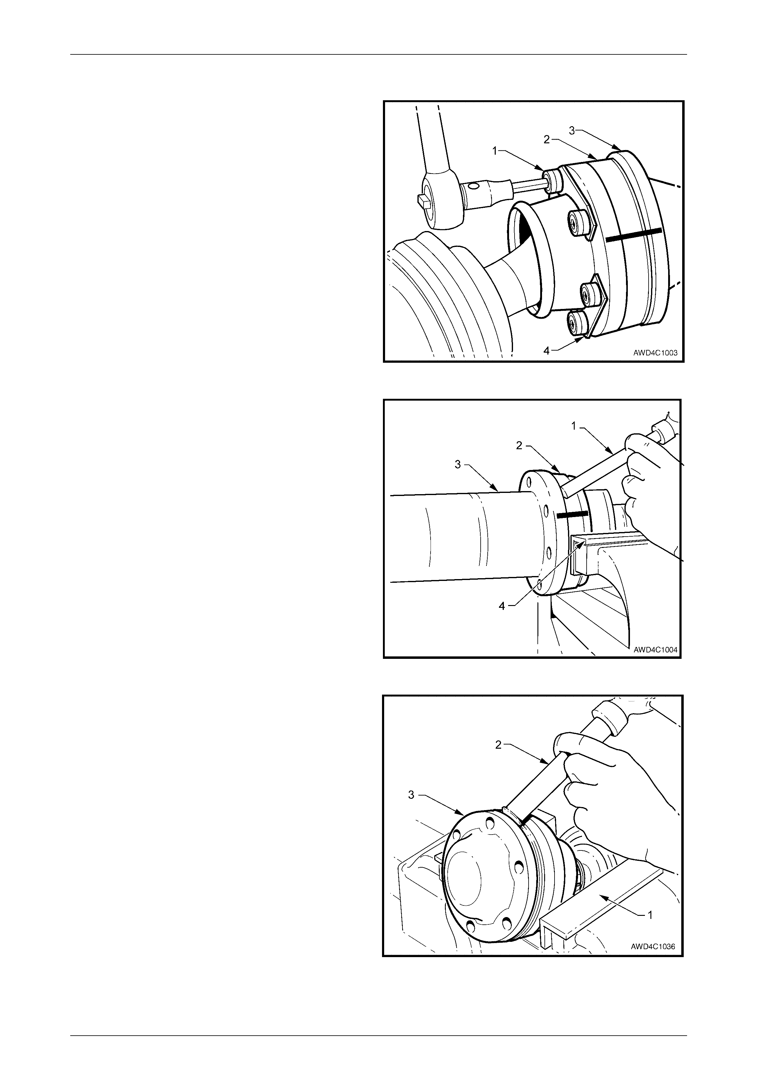
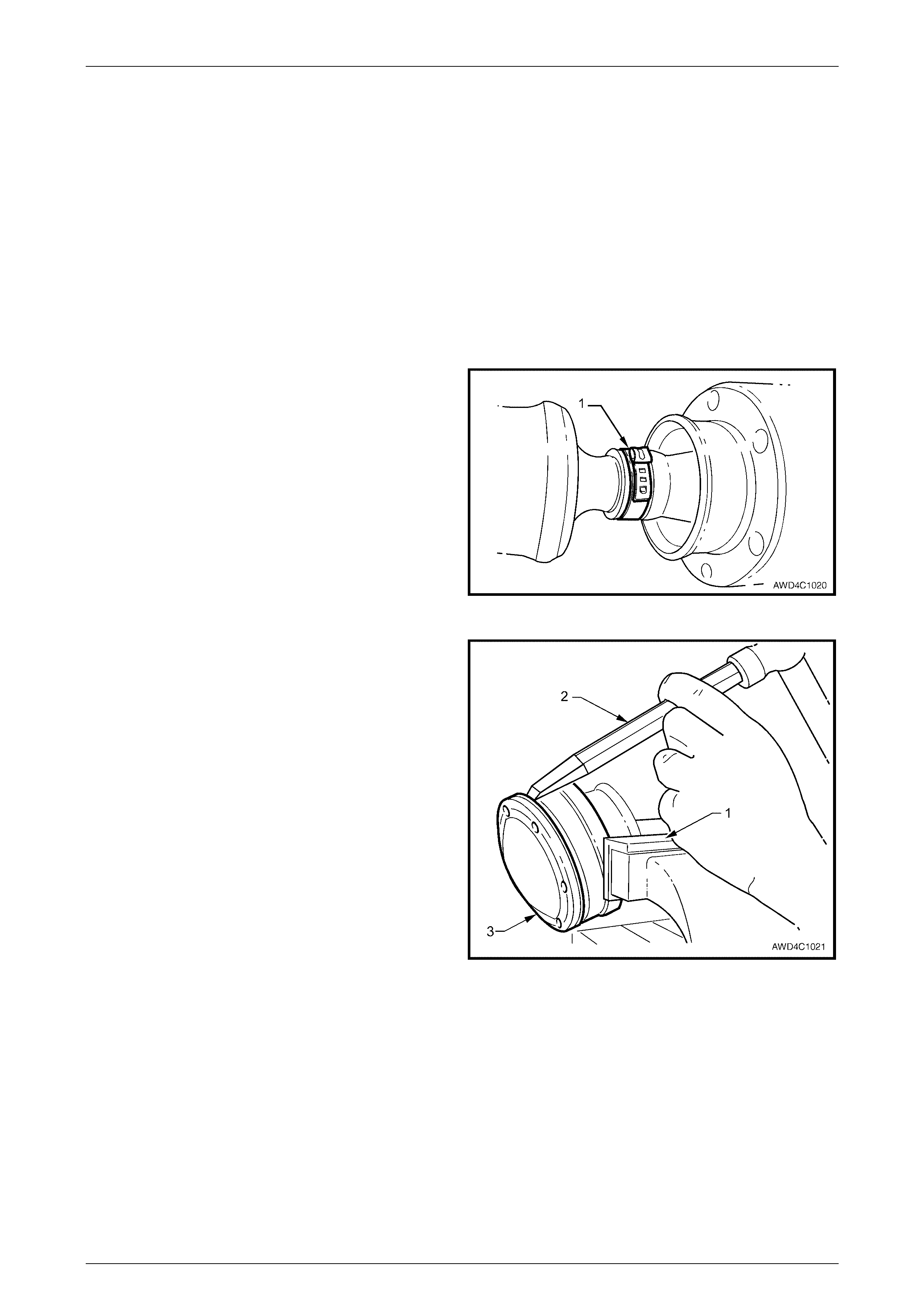
2 Using a back- up spa nner on each of the three
propeller shaft to coupli ng bolts (3), loosen then
remove the nuts (1) and washers (2). Discard the
removed bolts, nuts and washers. Remove the
coupling from the front of the propeller shaft.
Figure 4C1 – 5
3 Apply 0.5 gm of molybdenum disu lph ide grea se ( su ch
as Molybond GA10 or Shell ML10) to the spigot bush
in the propeller shaft end.
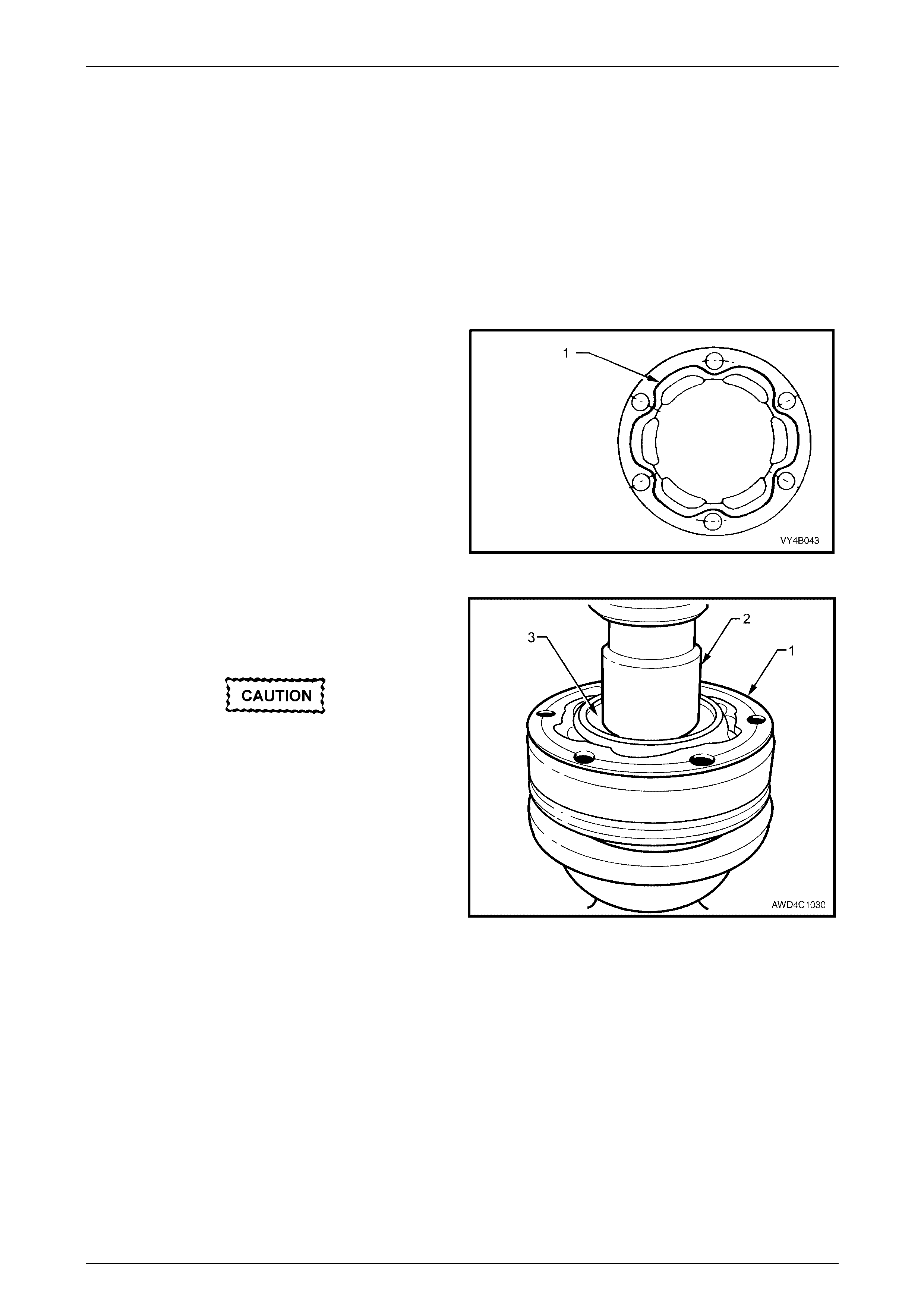
4 Reinstall a replacement rubber coupling onto the end
of the propeller shaft, aligning the holes in such a way
that the triangular shape (‘A’) on the coupling ‘points’
to the propeller shaft flange (1), as shown.
5 Install NEW bolts, washers and nuts to secure the
coupling to the propeller shaft flange and tighten to the
correct torque specification, using a back-up spanner
on the bolt head.
( ! ) Propeller shaft to rubber
coupling nut
torque specific atio n .............18 Nm, then 55 ° Turn Angle
6 Install the propeller shaft, as detailed in 2.1 Propeller
Shaft in this Section.
Figure 4C1 – 6
Rear Propeller Shaft & Universal Joints Page 4C1–7
Page 4C1–7
2.3 Centre Constant Velocity Joint
LT Section No. – 05-050
There are two repair kits available, for this centre, constant velocity joint repairs:
a A DUST SHIELD KIT, which contains dust shield, gasket, strap, and tubes of grease and sealant (or gasket).
b A CONSTANT VELOCITY JOINT KIT, which contains the same items as in the DUST SHIELD KIT, plus the
constant velocity joint and appropriate retaining circlips.
Remove
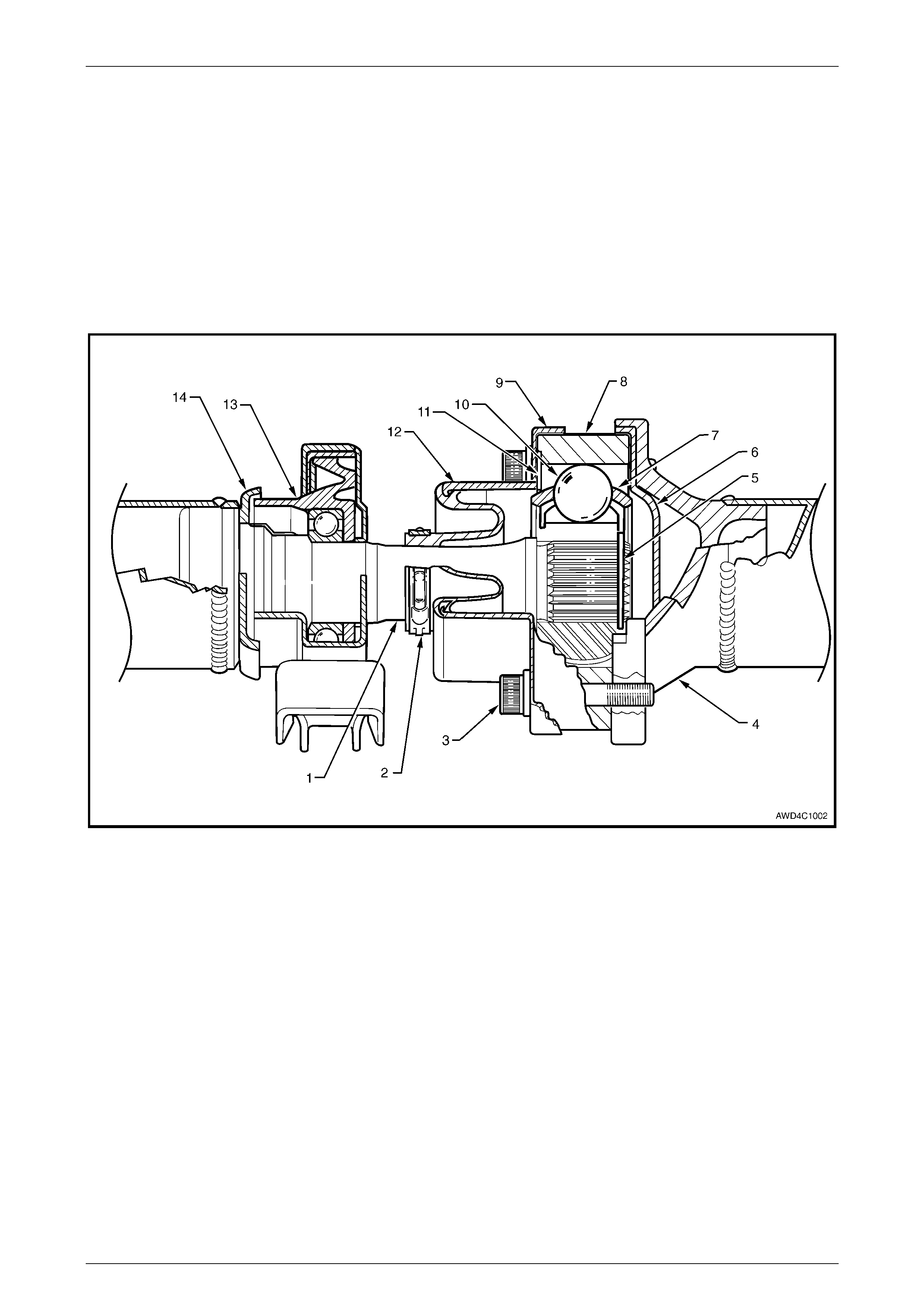
Figure 4C1 – 7
Legend
1 Propeller Shaft – Front Section
2 Boot Clamp
3 Allen Key Headed Screws - 6 Places
4 Propeller Shaft – Rear Section
5 Circlip
6 Domed End Cover
7 Constant Vel ocity J oi nt Ball Cage
8 Front Constant Velocity Joint Assembly
9 Dust Shield
10 Ball Bearing (6 places)
11 Gasket
12 Dust Boot
13 Centre Bearing and Support Bracket Assembly
14 Slinger
Rear Propeller Shaft & Universal Joints Page 4C1–8
Page 4C1–8
1 Remove propeller shaft. Refer to 2.1 Propeller Shaft in this Section.
2 To ensure correct alignment of parts at reassembly,
scribe an aligning mark on constant velocity joint (2)
and the rear propeller shaft mounting flange (3).
3 While holding the rear half of the propeller shaft in a
vice fitted with soft jaws, remove the six, 6 mm Allen
key headed screws (1) and three lock plates (4), using
suitable socket equipment.
Figure 4C1 – 8
4 Secure the front constant velocity joint is a vice fitted
with soft jaws (4).
5 Using a hammer and a brass drift, tap the rear
propeller shaft companion flange evenly from constant
velocity joint.
Figure 4C1 – 9
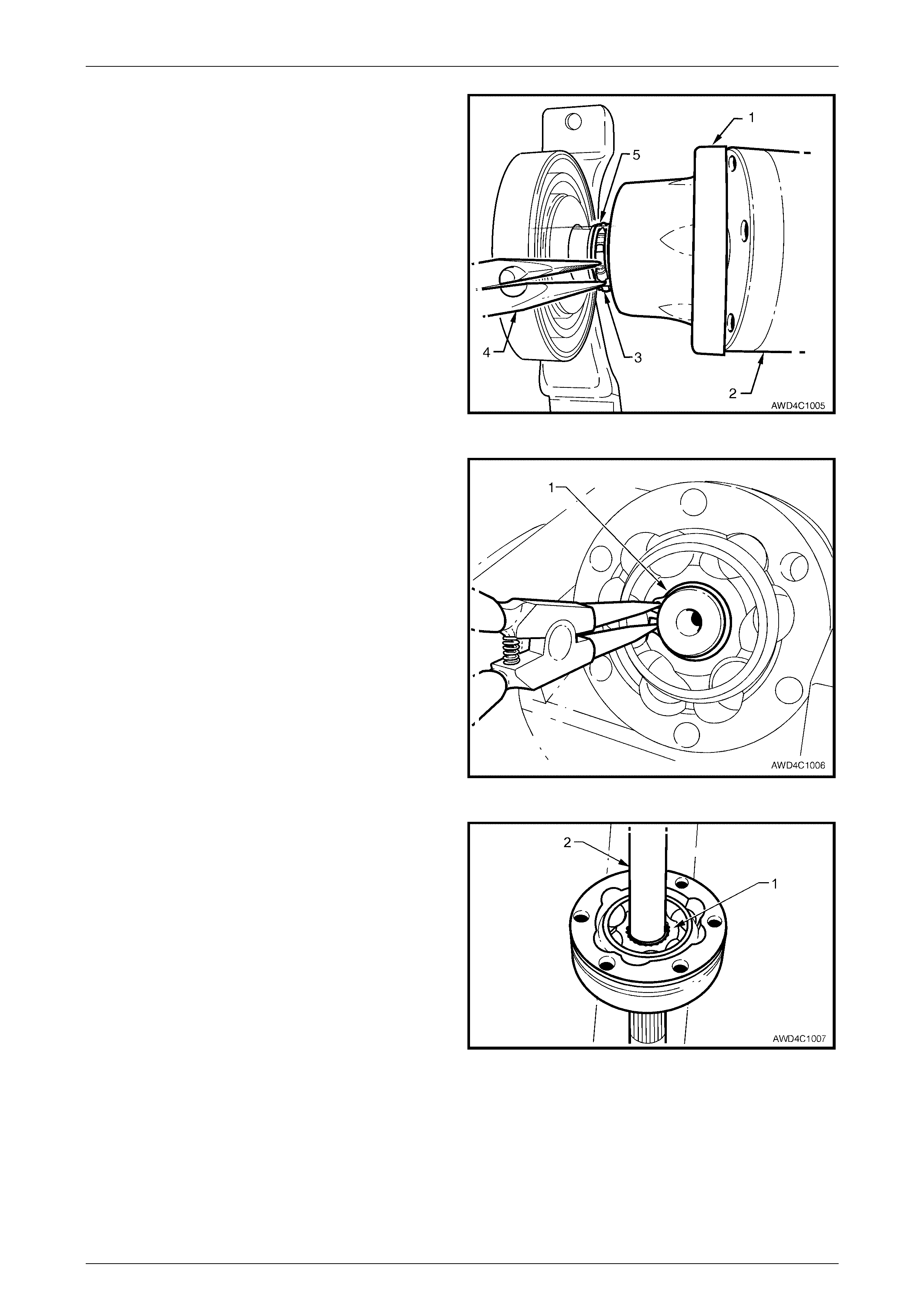
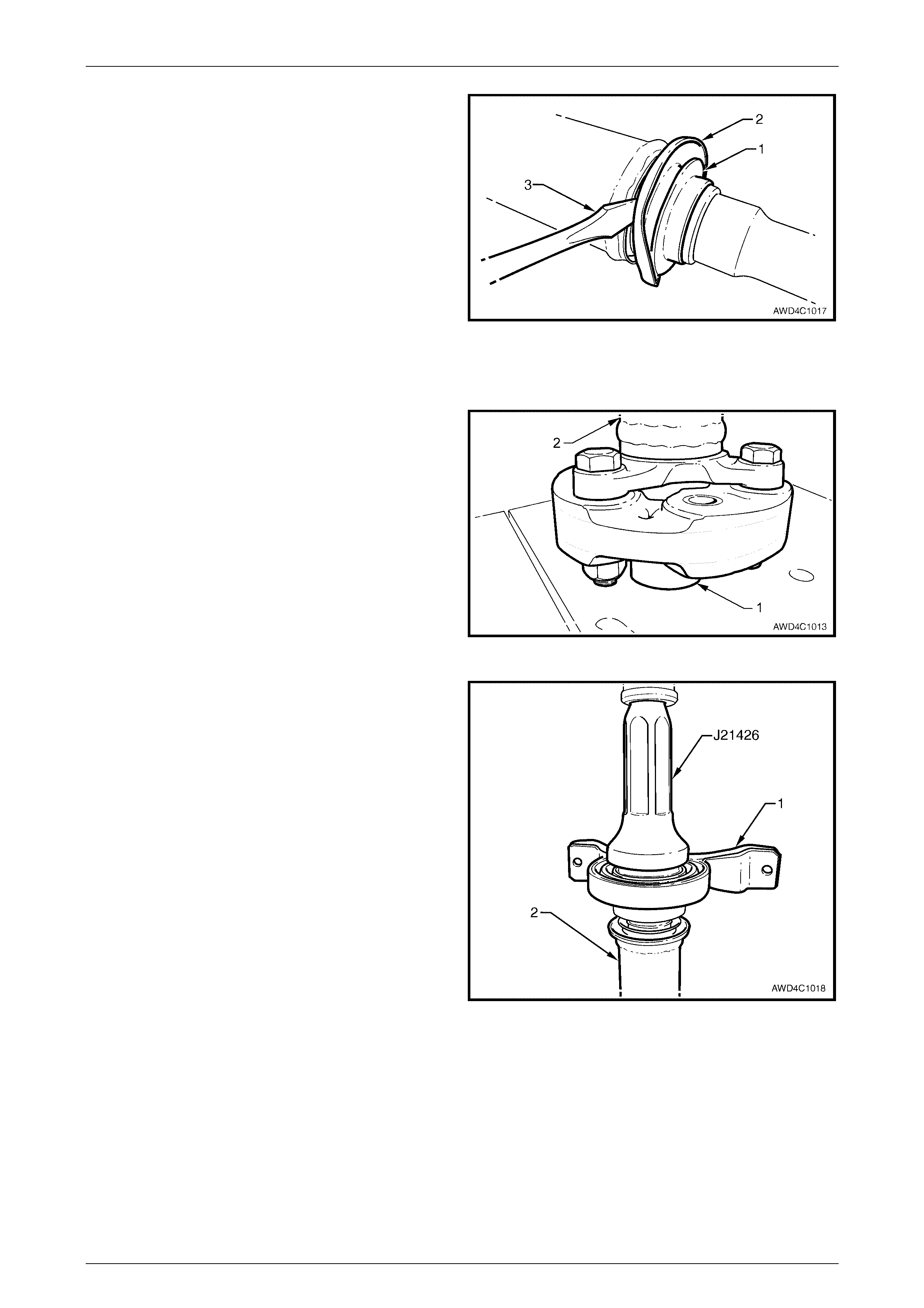
6 W hile still secured in the soft jaws (1) of a vice, use a
brass drift (2) and hammer, dislodge, then remove the
dust shield cap (3) from the end of the constant
velocity joint. Discard the removed cover.
Figure 4C1 – 10
Rear Propeller Shaft & Universal Joints Page 4C1–9
Page 4C1–9
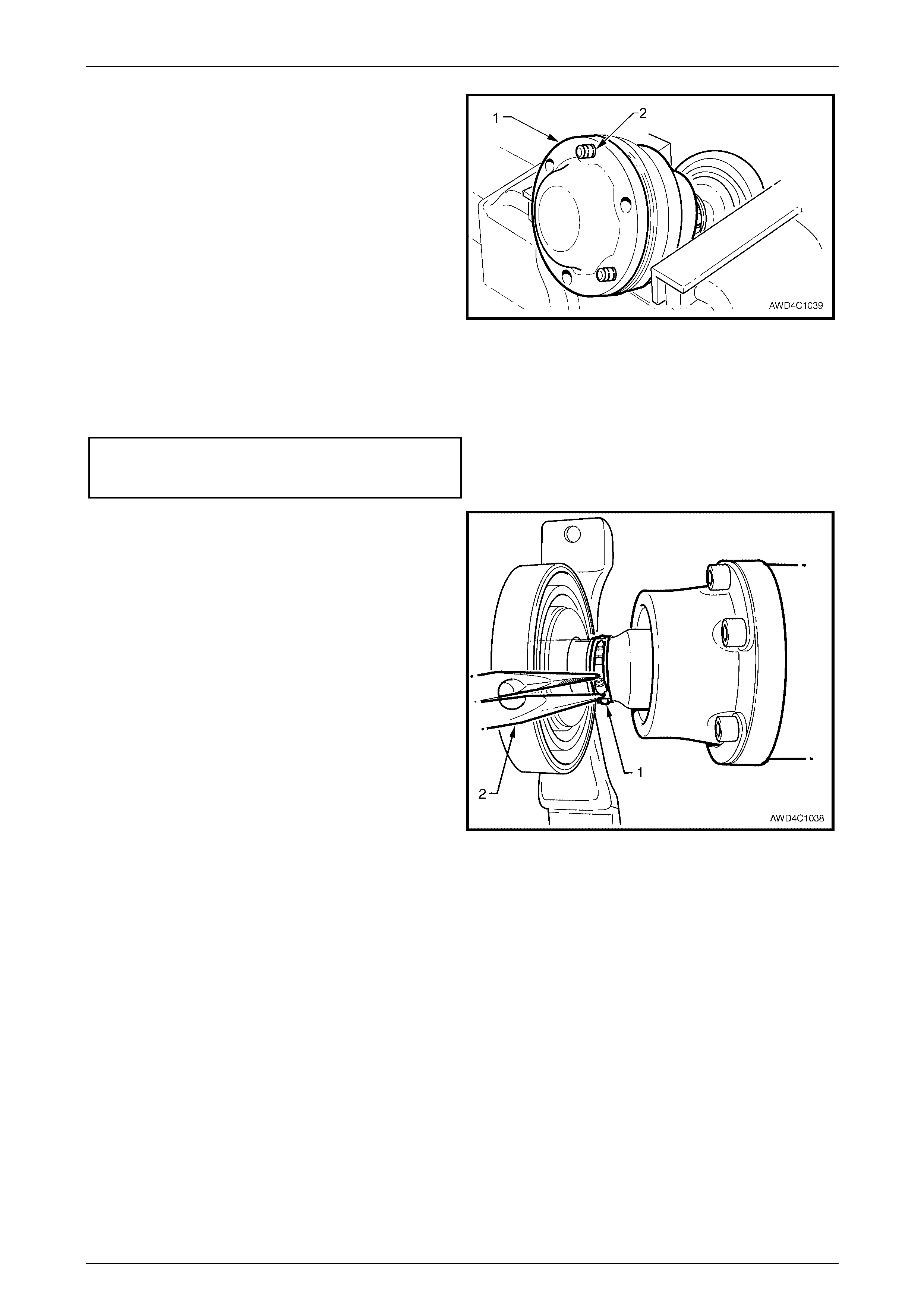
7 Reposition the constant velocity joint in the soft faced
vice jaws, then use a brass drift and hammer to tap
constant velocity joint dust shield (1) to dislodge it from
the constant velocity joint (2).
8 While tensioning the boot clamp (3) with long nosed
pliers (4), use a small bladed screwdriver to lever the
clamp tang (5) releasing it from the clamp barbs.
Remove and discard the clamp.
Figure 4C1 – 11
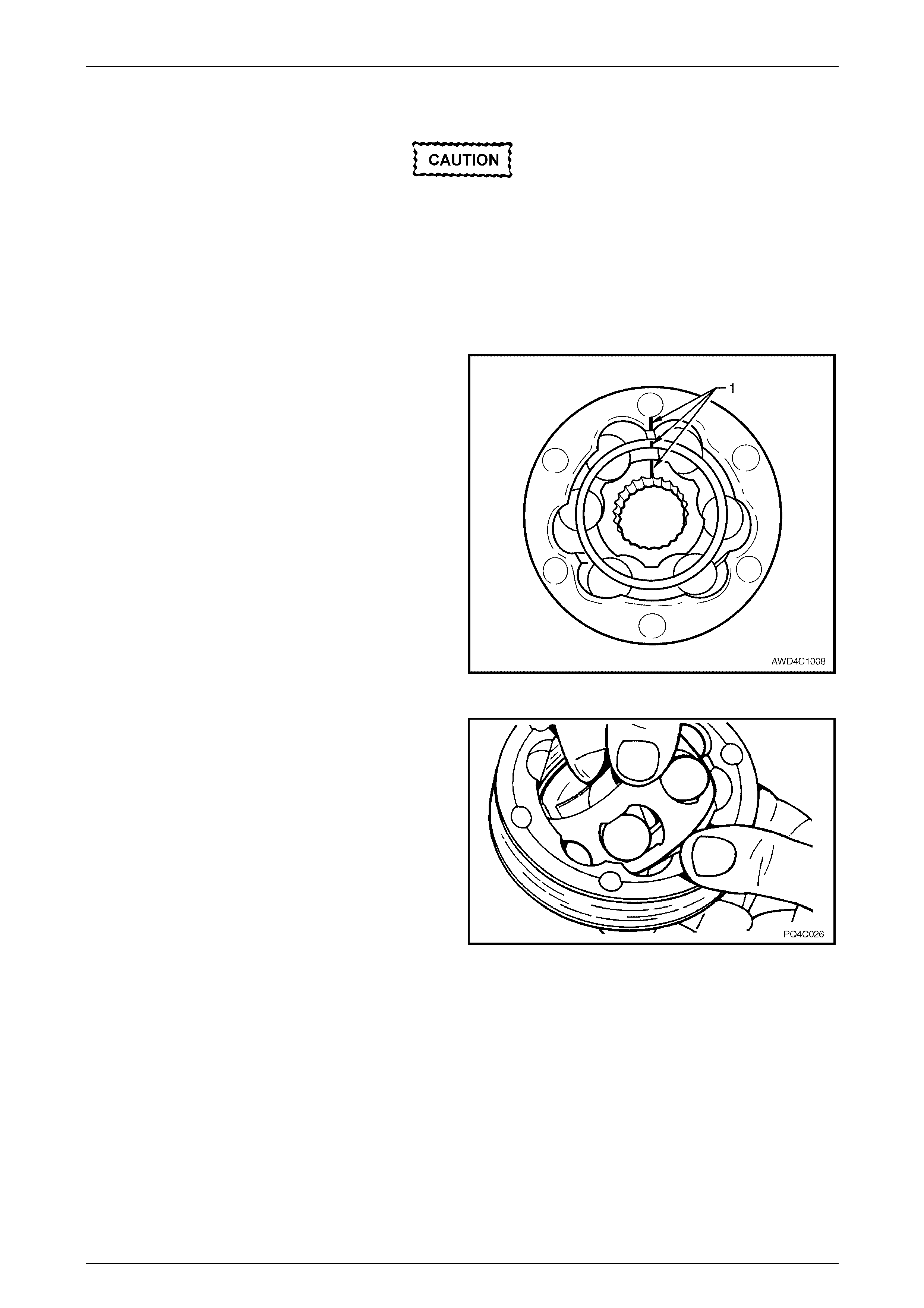
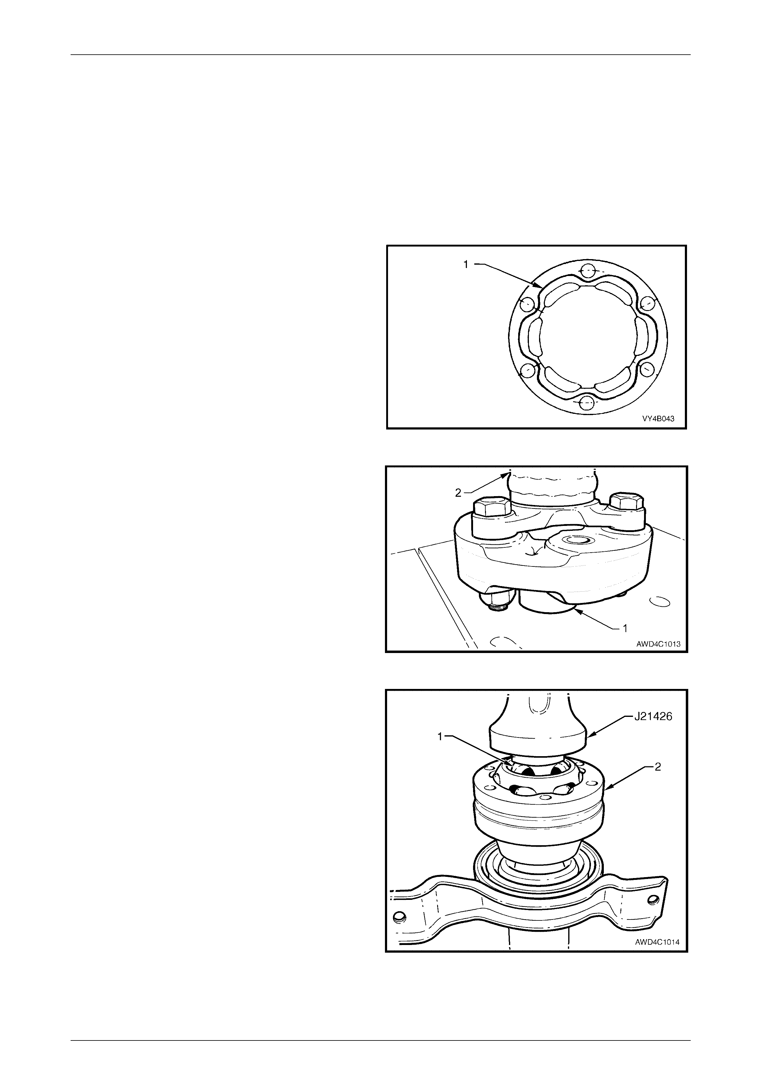
9 W ipe excess lubricant from the constant velocity joint,
then remove the retaining circlip (1).
Figure 4C1 – 12
10 Pull back constant velocity joint outer race. Install
suitable press plates (approximately 8 mm thick),
between dust shield and constant velocity joint, to
support inner joint race (1). Press the front half of
propeller shaft from constant velocity joint, using a
suitable drift (2).
NOTE
Press plates J22912-01 are too thick to fit
between the constant velocity joint and the dust
shield.
11 Clean old gasket material from dust shield and
constant velocity joint mating surfaces.
Figure 4C1 – 13
Rear Propeller Shaft & Universal Joints Page 4C1–10
Page 4C1–10
Disassemble
Disassembly of the constant velocity joint is
not recommended. The internal components
are a precision fit and develop their own
characteristic wear patterns. Intermixing
components could result in looseness,
binding and/or subsequent premature failure
of the joint. However, if disassembly must be
attempted, then it is vital that the following
procedure is carefully followed.
1 Remove the excess lubricant from the constant
velocity joint, wipe clean and mark the relationship of
the inner race, ball guide and outer race, using
correction fluid.
Figure 4C1 – 14
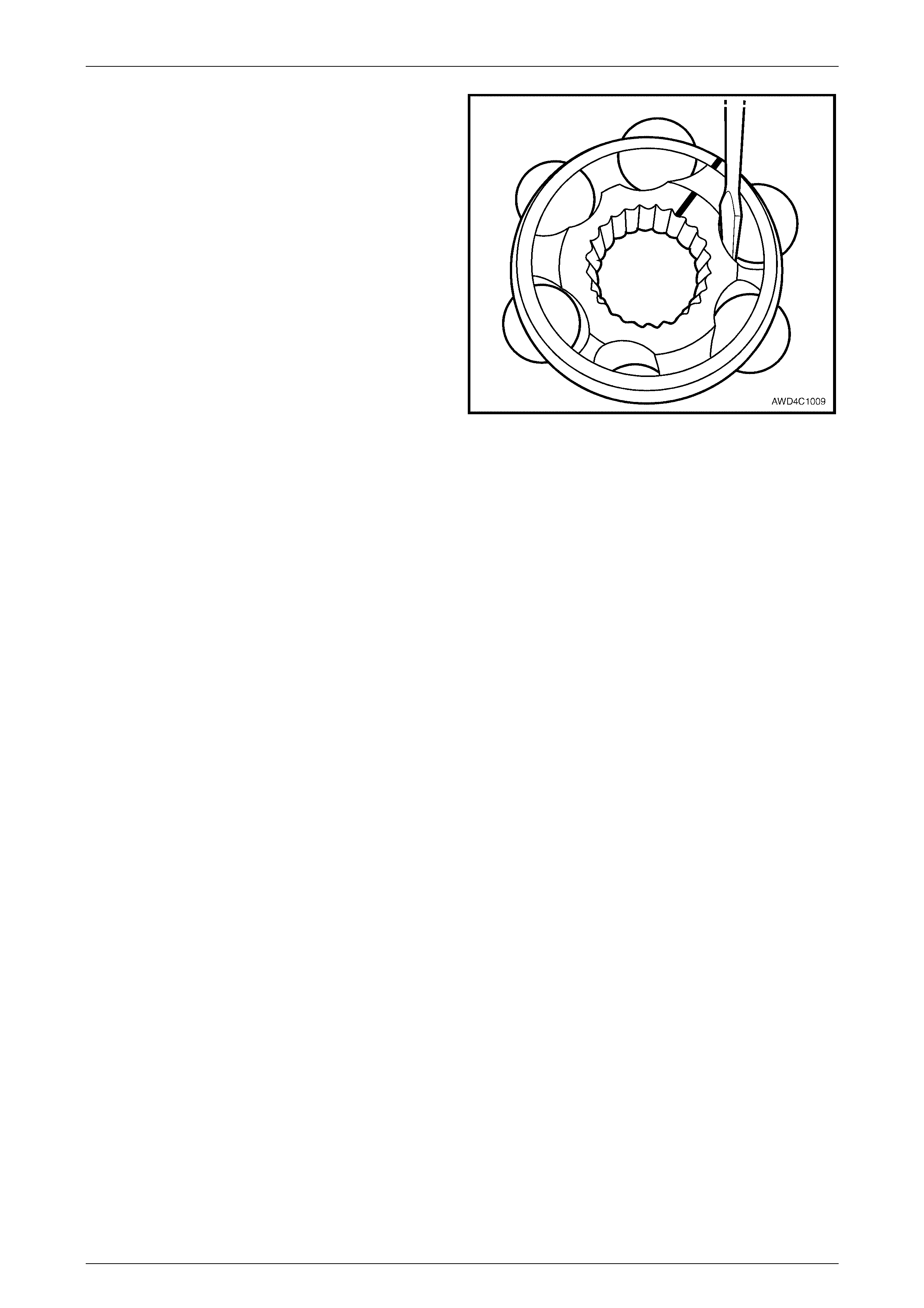
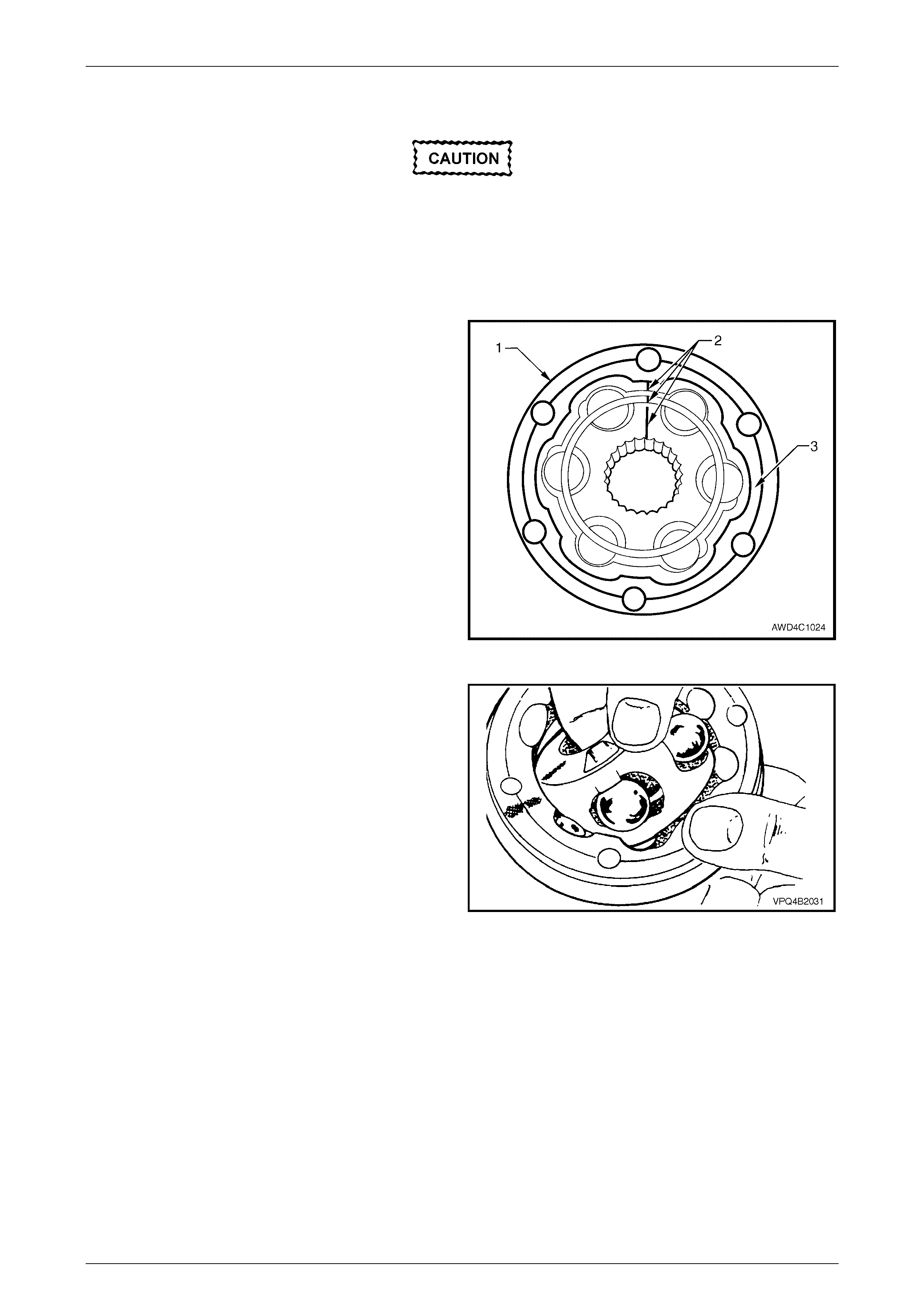
2 Pivot inner race and ball guide at 90° to centre line of
outer race as shown, and lift inner race, ball guide and
six balls as an assembly, from outer race.
NOTE
Even with grease surrounding the constant
velocity joint components, be careful not to allow
any balls to slip from the cage. Each ball must
be reinstalled in its original position.
Figure 4C1 – 15
Rear Propeller Shaft & Universal Joints Page 4C1–11
Page 4C1–11
3 Using a small screwdriver, lever balls from guide, as
shown. Keep balls in order, relative to the alignment
marks made in Step 1, for reassembly.
NOTE
Dependent on the length of time the constant
velocity joint has been in service, individual balls
could slip from the cage and not require prising
to release.
4 Lift the inner race from the ball guide.
Figure 4C1 – 16
Inspect
Propeller Shaft and Boot
1 Clean propeller shaft, boot and dust shield in a suitable cleaning solvent.
2 Inspect propeller shaft for visible damage and twisting, cracking or excessive spline wear.
NOTE
If any damage is evident then the propeller shaft
must be replaced.
3 Inspect boot and dust shield, replacing if split, fatigued, cracked or worn.
4 Check that the vent hole in the front flange of the rear propeller shaft half, is clear and not blocked with mud or
other debris.
Constant Velocity Joint
1 Inspect the grease in the joint for contamination and/or dirt ingress. If either of these conditions is evident, then the
constant velocity joint will most probably have suffered damage and should be replaced. If inspection shows that
the joint has not been contaminated, clean the joint by soaking in a suitable cleaning solvent.
2 Clean all components in suitable solvent, ensuring that the part relationships remain undisturbed.
3 Carefully inspect all components for signs of severe pitting, galling, play between balls and the cage windows, any
cracking or damage to cage, pitting or galling or chips in raceways. Replace the constant velocity joint if any of
these conditions are evident.
Rear Propeller Shaft & Universal Joints Page 4C1–12
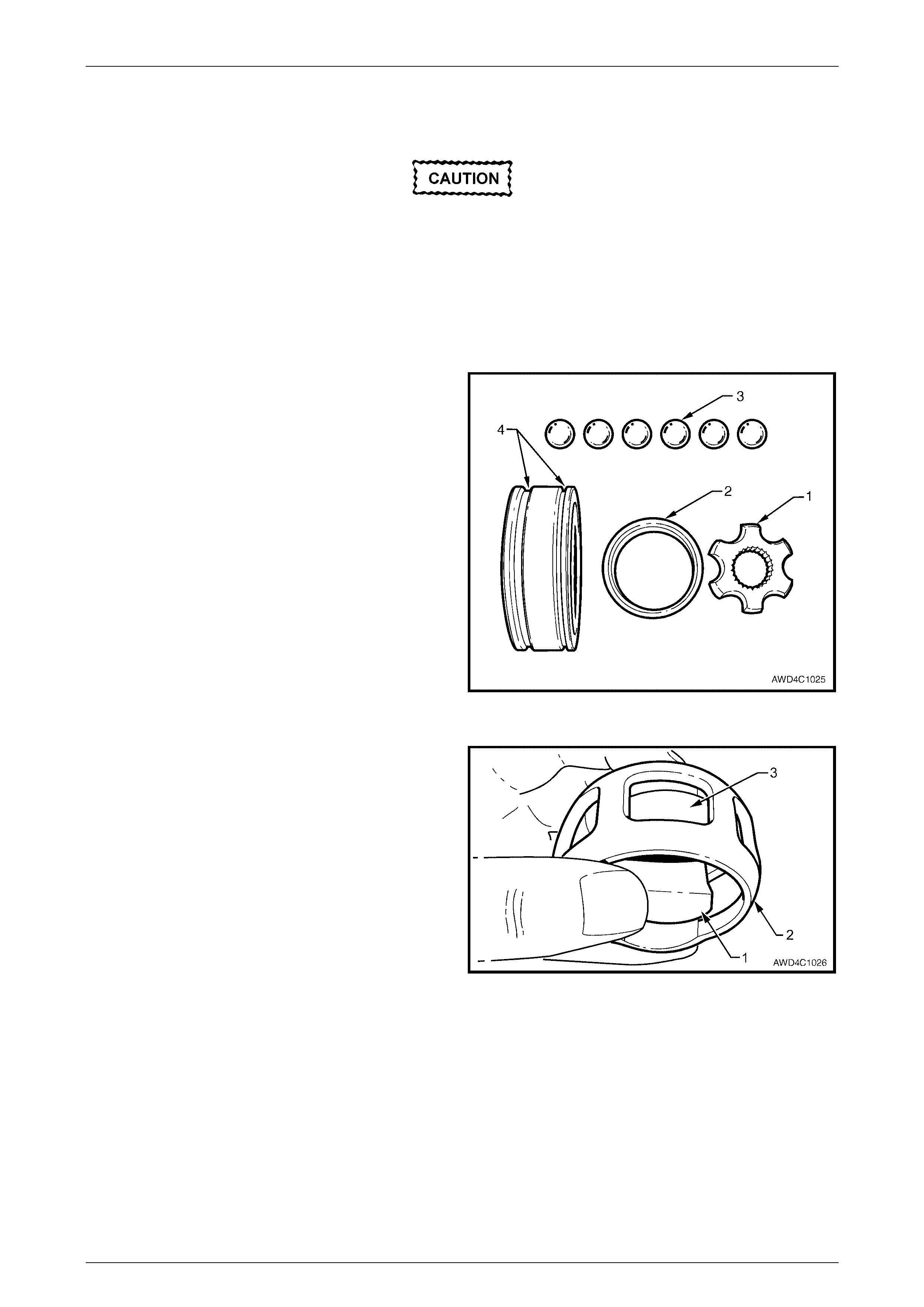
Page 4C1–12
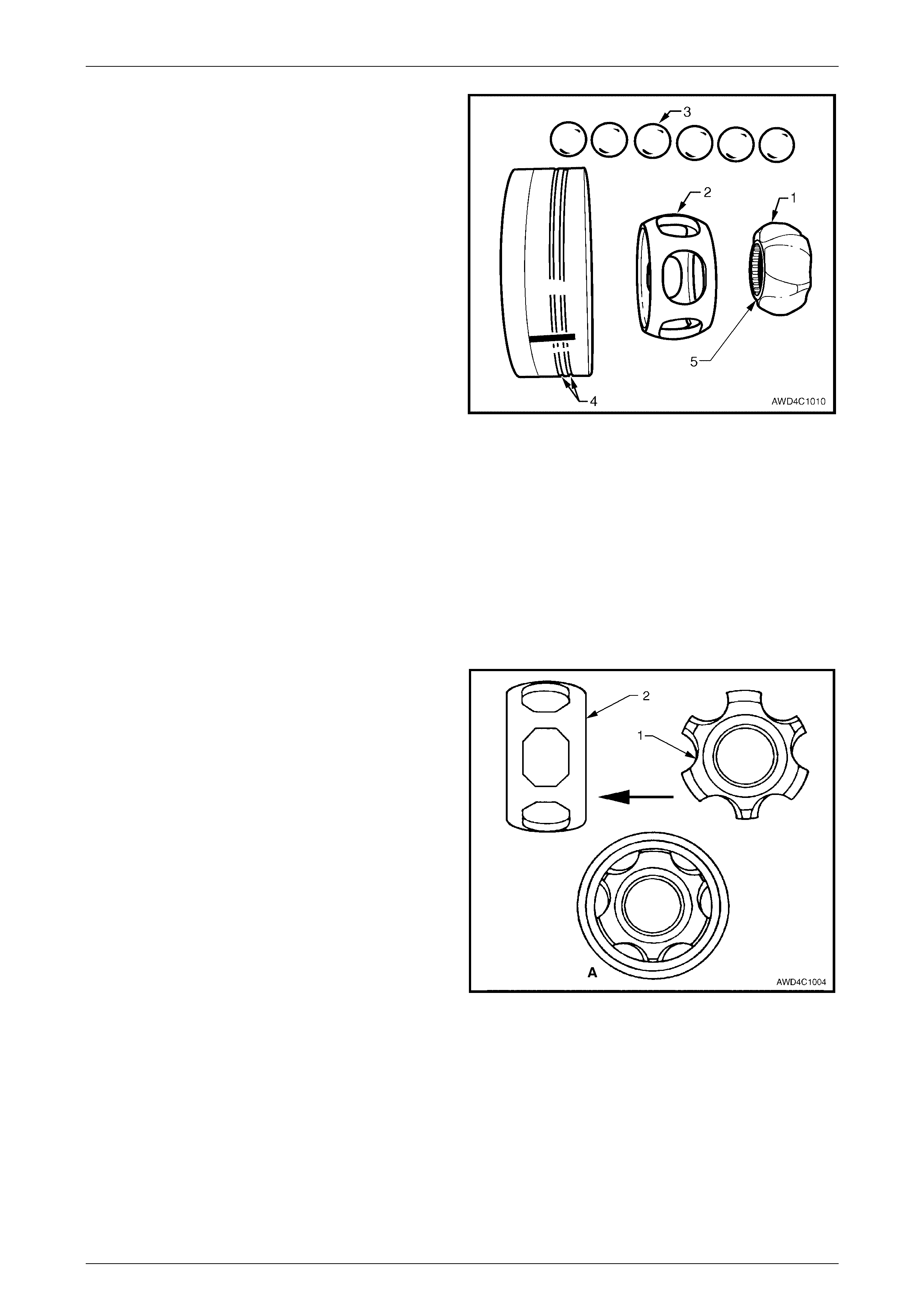
Shown is an exploded view of the centre propeller shaft
constant velocity joint. Note the two identification grooves on
the outer race (4) and the step (5) on the inner race (1).
These features and the angled ball tracks, identify that this
is a ‘plunge’ joint, when assembled.
NOTES
• The inner race (1) and cage (2), together with
the individual balls (3), must be maintained in
their original locations to minimise the
creation of a noisy joint.
• Under no circumstances are components
from one constant velocity joint to be mixed
with components from another constant
velocity joint.
Figure 4C1 – 17
Reassemble
Method 1
1 Provided the balls are held captive in the ball cage when installed, reinstall each in its correct position.
2 While holding the inner race, cage and the six balls in position, reinstall to the outer race by turning the inner
assembly at 90° to the outer race, reinstall the two balls in their raceways, then rotate the inner assembly, to fully
reinstall. Refer to Figure 4C1-14. Check that the relationship marks are aligned, refer to F i gure 4C1-13.
Method 2
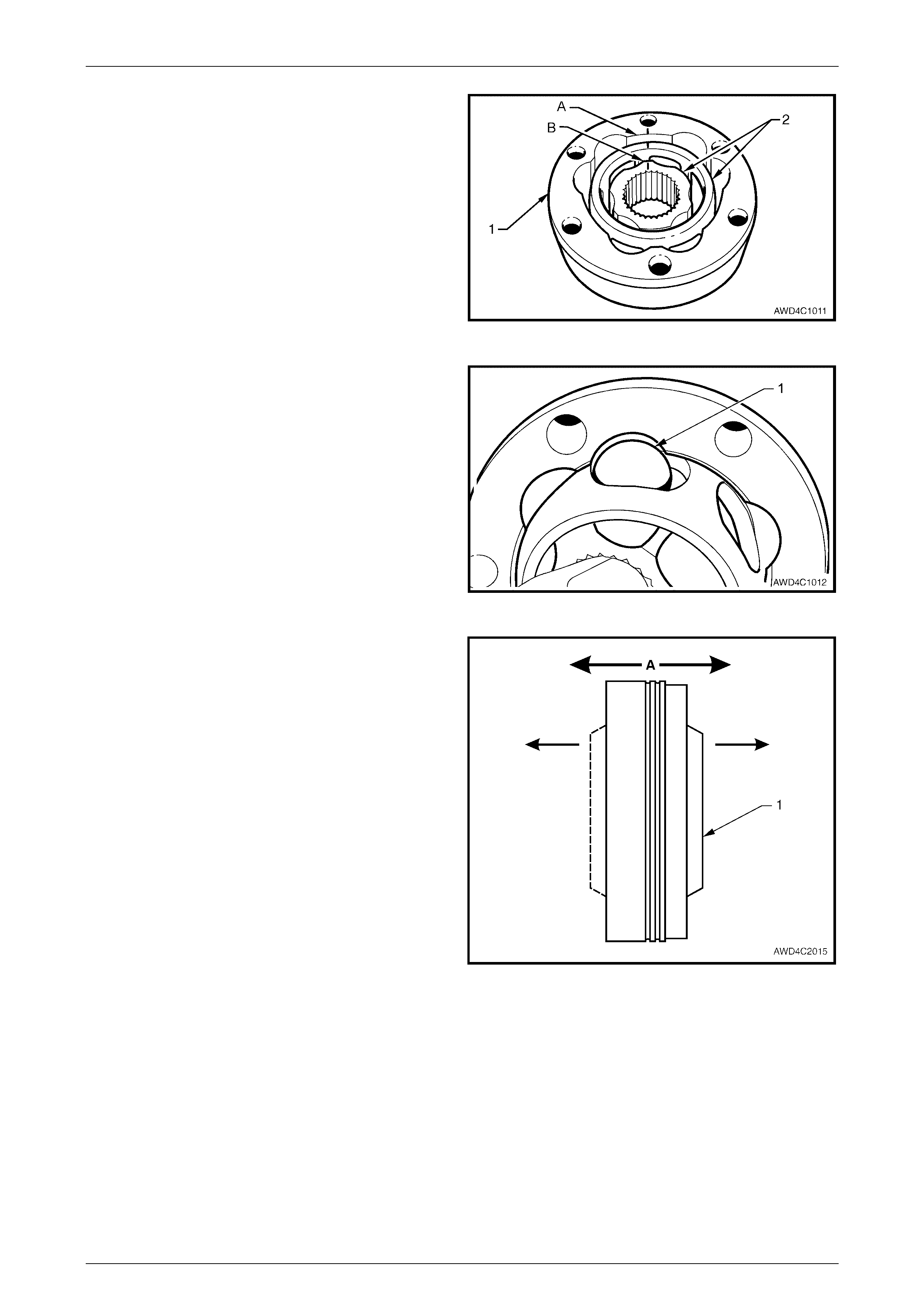
1 Place the inner race (1) into the cage (2) and position
centrally within the cage, as shown in view ‘A’. Align
the relationship marks to confirm corr ect insta llation.
NOTE
The flange on the inner diameter of the inner
race should be on the same side as the chamfer
on the inner edge of the ball cage.
Figure 4C1 – 18
Rear Propeller Shaft & Universal Joints Page 4C1–13
Page 4C1–13
2 Place the inner race and cage (2) into the outer race
(1), as shown.
3 Align a thick section (A) on the outer race, with a
narrow one (B) on the inner race. Note that the
relationship marks are also in alignment.
Figure 4C1 – 19
4 Tilt the cage and inner race as shown, and fit the first
ball (1) in its original location.
Repeat this process for the remaining five balls.
Figure 4C1 – 20
5 W hen assembly of the constant velocity joint is
complete, check for plunge movement of the inner
members (1), indicated by ‘A’. If NO plunge movement
can be achieved, then the constant velocity joint has
NOT been correctly assembled.
If such a situation occurs, the constant velocity joint
must be disassembled and the assembly process
repeated until such time that the required plunge
movement is achieved.
NOTE
The total plunge movement for the centre
constant velocity joint should be approximately
28 mm.
Figure 4C1 – 21
Rear Propeller Shaft & Universal Joints Page 4C1–14
Page 4C1–14
Reinstall
Installation is the reverse of removal procedure, noting the following points:
1 Cleanliness of con stant velo cit y joint and assoc iate d part s is v ital to ensure maximum life.
2 Install a new boot clamp at the small end of the dust boot.
3 Pack the constant velocity joint with the lubricant supplied in either of the two available Repair Kits. Work joint by
hand to distribute grease onto all surfaces inside the joint.
4 Clean mating surfaces of constant velocity joint, dust shield and rear propeller shaft companion flange.
5 Apply a 2 mm bead of Loctite 510 High Temperature
Gasket Eliminator sealant or equivalent to dust shield
mating surface on the constant velocity joint, as shown
(1). Take care not to contaminate the constant velocity
joint grease with sealant.
Figure 4C1 – 22
6 Before pressing the constant velocity joint onto the
splined propeller shaft, support the shaft end (2) with a
suitable length of tube (1) of dimensions 48 mm OD,
32 mm ID and at least 30 mm long.
Figure 4C1 – 23
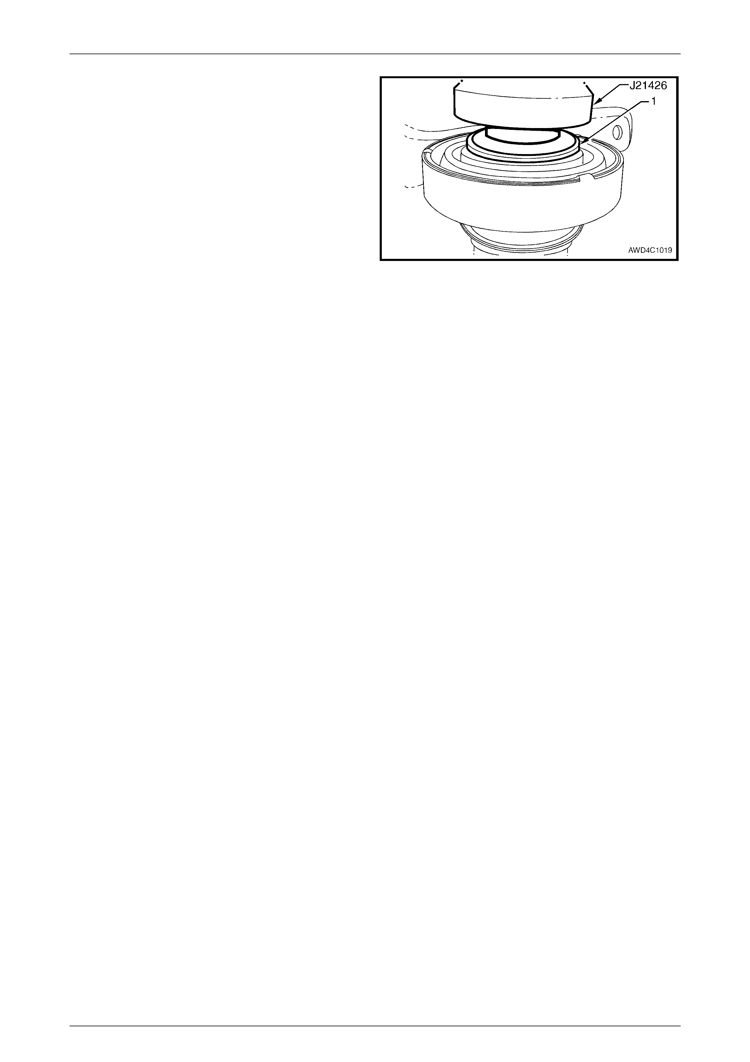
7 Press constant velocity joint (2) onto shaft using
installer J21426 or a suitable size socket or tube.
Ensure that the press force is applied to the inner race
(1), as shown.
8 Using circlip pliers, install a new circlip to retain the
constant velocity joint. Be careful not to over-expand
the circlip during the installation process.
9 Insert three attaching bolts through the dust boot
flange to align with the constant velocity joint, then tap
the dust boot flange assem bly into pla ce.
10 Clean threads in rear propeller shaft companion flange
and the six Allen head bolts. Apply Loctite 242 or
equivalent thread sealant to the bolt threads.
11
A
pply Loctite 510 High Temperature Gasket Eliminator
sealant or equivalent, to the flanged area of propeller
shaft companion flange, in a similar manner to that
shown in Figure 4C1-22.
Figure 4C1 – 24
Rear Propeller Shaft & Universal Joints Page 4C1–15
Page 4C1–15
12
A
pply Loctite 510 High Temperature Gasket Eliminator
sealant or equivalent, to the flanged area of the
propeller shaft companion flange, in a similar manner
to that shown in Figure 4C1-22.
13 With the three attaching bolts (2) still installed through
the dust boot flange and constant velocity joint, insta ll
then tap a new dust boot cover (1) into place, over the
constant velocity joint.
14 Clean threads in rear propeller shaft companion flange
and the six Allen head bolts. Apply Loctite 242 or
equivalent thread sealant to the bolt threads.
Figure 4C1 – 25
15 Ensure that the relationship marks on the constant velocity joint, dust boot flange and rear propeller shaft flange
(made before disassembly), are all aligned.
16 Reinstall and tighten the six Allen headed screws to the correct torque specification.
( # ) Centre constant velocity joint to
rear propeller shaft flange bolt
torque specific atio n ..............................................35 Nm
17 After locating the boot into the rece ss in the dust boot
groove, tighten the new clamp (1) using long nosed
pliers (2). Ensure that the end of the clamp strap
engages with the last two barbs of the clamp.
18 Reinstall propeller shaft. Refer to 2.1 Propeller Shaft in
this Section.
Figure 4C1 – 26
Rear Propeller Shaft & Universal Joints Page 4C1–16
Page 4C1–16
2.4 Centre Bearing Assembly
LT Section No. – 05-050
NOTES
• This bearing cannot be removed from the
propeller shaft without causing damage to the
rubber ball race carrier and housing
assembly. New parts must be installed when
the propeller shaft is being reassembled.
• The replacement centre bearing kit contains
front and rear dust slingers, centre bearing
and rubber cup assembly.
Remove
1 Remove propeller shaft, refer to 2.1 Propeller Shaft in this Section.
2 Remove constant velocity joint, refer to 2.3 Constant Velocity Joint in this Section.
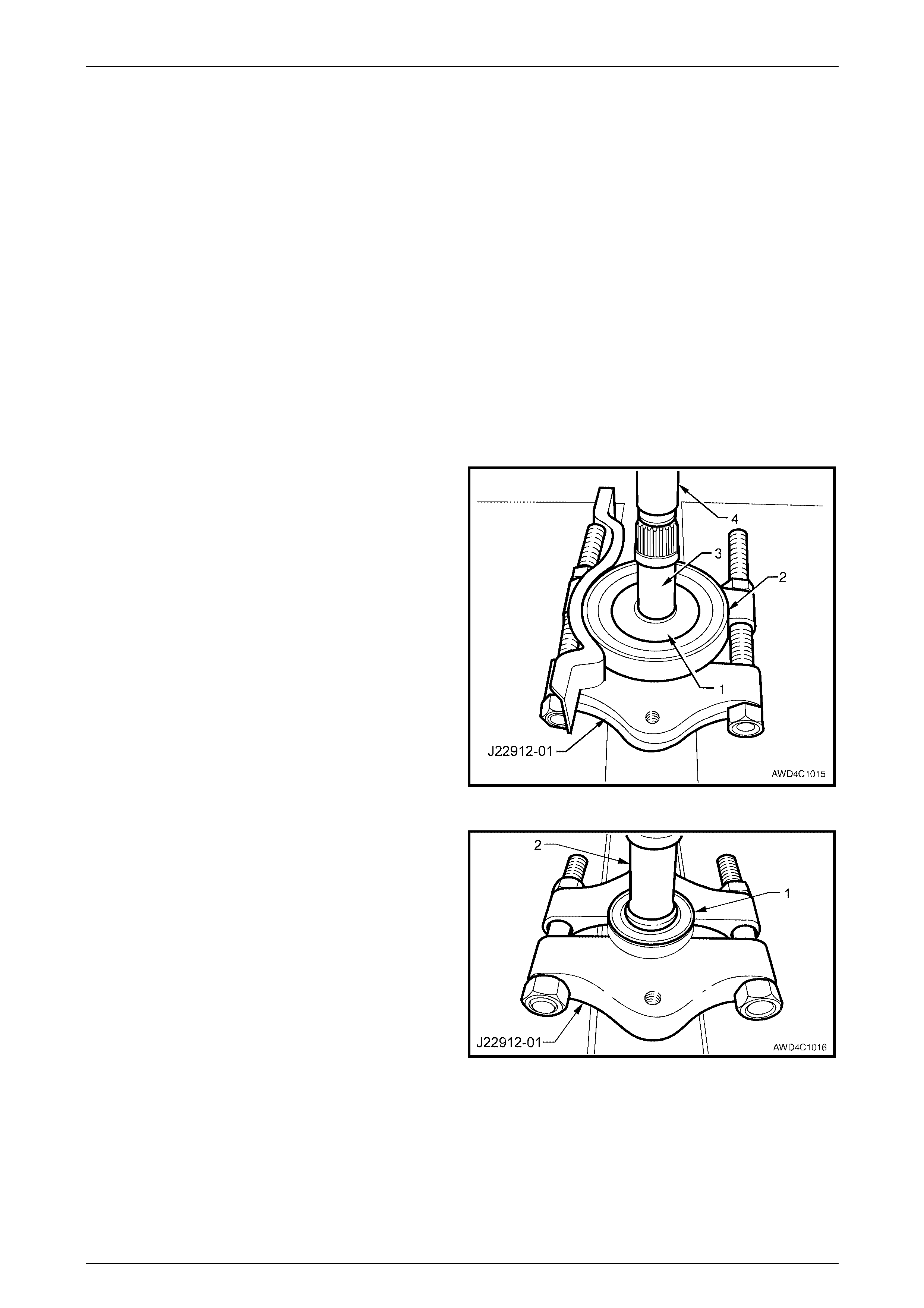
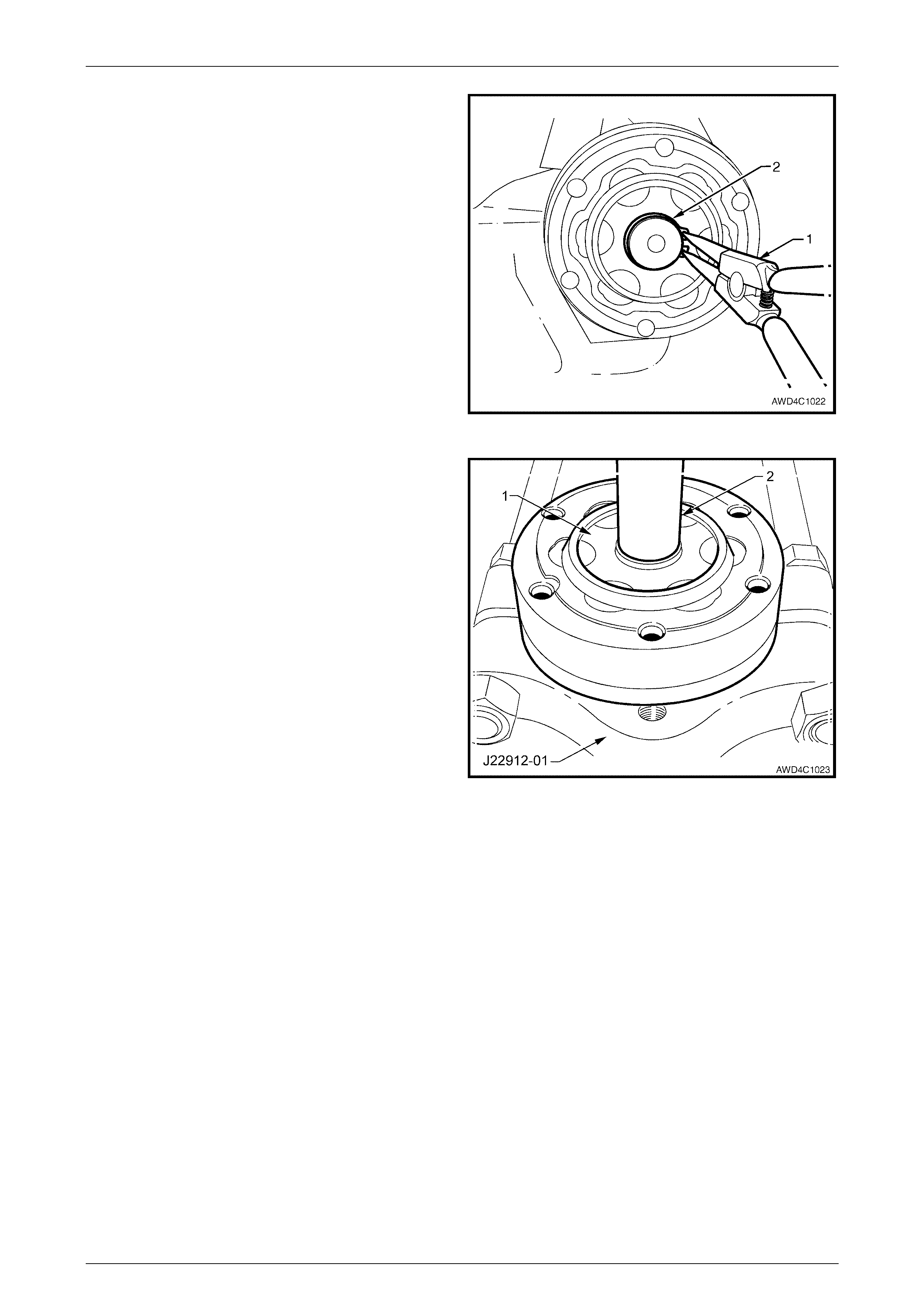
3 Using suitable press plates, such as J22912-01 or
equivalent and a suitable drift (4), support rubber ball
race carrier and housing assembly (2), then press the
propeller shaft (3) from the rear slinger (1) and rubber
ball race carrier and housing assembly (2).
NOTE
This action will separate the bearing from the
rubber support, requiring the replacement of the
complete assembly.
Figure 4C1 – 27
4 Support the centre bearing (1) with suitable press
plates such as J22912-01, then press the propeller
shaft front half (2) from the bearing. Discard the
bearing (1) following removal.
Figure 4C1 – 28
Rear Propeller Shaft & Universal Joints Page 4C1–17
Page 4C1–17
5 If required, remove centre bearing front slingers (1 and
2), using a suitable lever (3), such as a flat bladed
screwdriver.
NOTE
The slingers will be distorted during removal and
must be replaced with new parts on reassembly.
Figure 4C1 – 29
Reinstall
1 Install new front slingers (one at a time), onto front half
of the propeller shaft using J5590 or a suitable sized
tube.
NOTE
During this reinstallation process, ensure that the
front of the propeller shaft (2) is supported on a
suitable length of tube (1) (dimensions; 48 mm
OD, 32 mm ID and at least 30 mm long), as
shown.
Figure 4C1 – 30
2 Reinstall new centre bearing assembly (1) to propeller
shaft (2) using installer J21426 or a suitable size tube.
NOTE
Only apply press force to the centre ball race.
Figure 4C1 – 31
Rear Propeller Shaft & Universal Joints Page 4C1–18
Page 4C1–18
3 Again using installer J21426 or a suitable size tube,
install a new slinger (1) to the centre bearing, as
shown.
Figure 4C1 – 32
4 Reinstall centre constant velocity joint. Refer to 2.3 Centre Constant Velocity Joint in this Section.
5 Reinstall the rear propeller shaft assembly. Refer 2.1 Propeller Sha ft in this Section.
Rear Propeller Shaft & Universal Joints Page 4C1–19
Page 4C1–19
2.5 Fixed, Rear Constant Velocity Joint
LT Section No. – 05-050
NOTE
The rear propeller shaft, rear constant velocity
joint (constant velocity joint), is a “fixed” joint,
which means that any axial end play is minimal.
Remove
1 Remove rear propeller shaft from the vehicle. Refer to 2.1 Propeller Shaft, in this Section.
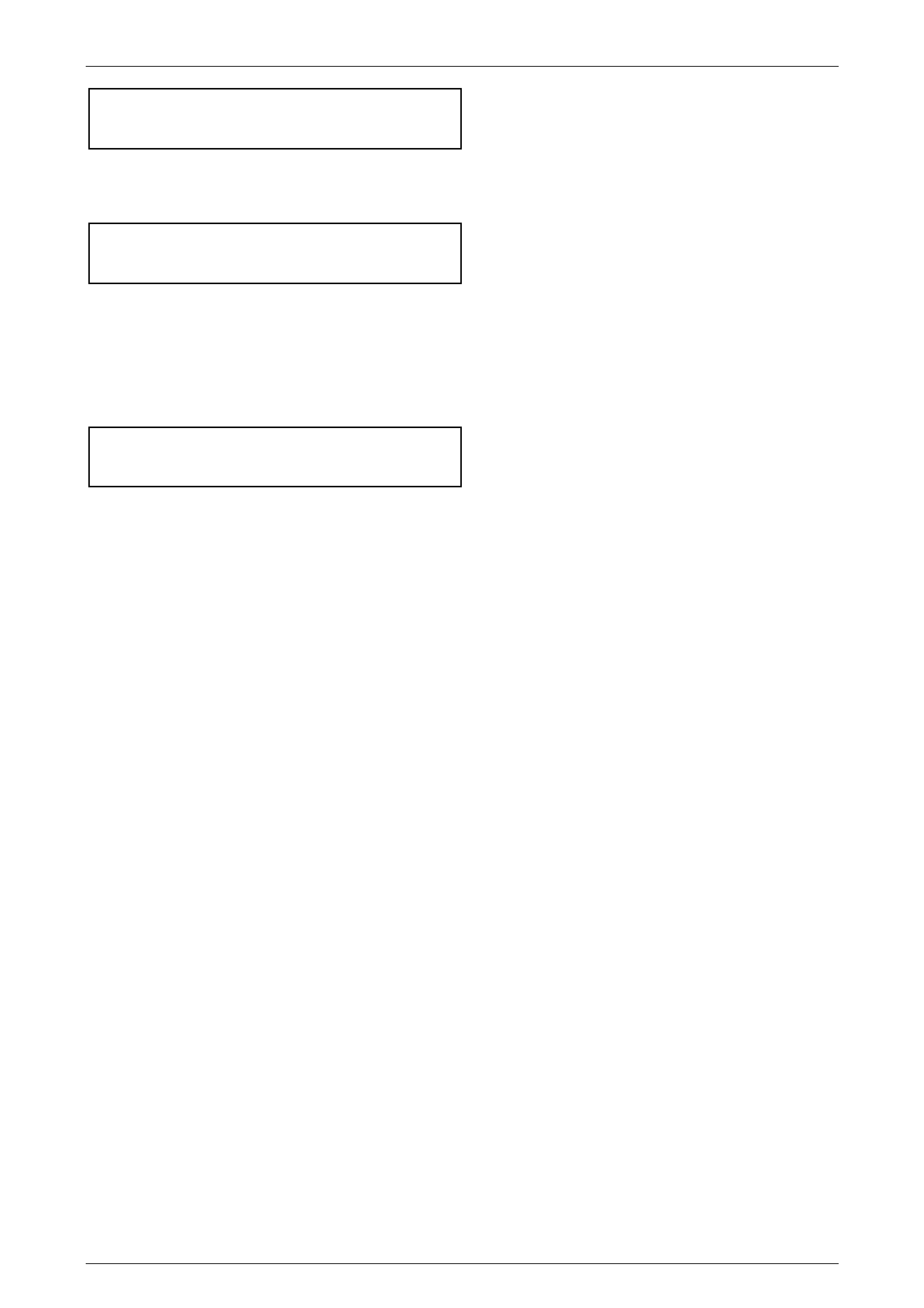
2 Using a small bladed screwdriver, lever up the boot
clamp tang to release, then remove and discard the
boot clamp (1).
Figure 4C1 – 33
3 Grip the constant velocity joint in a vice fitted with soft
jaws.
4 Using a suitable cold chisel and hammer, dislodge and
remove the crimped end cap from the end of the
constant velocity joint. Discard the removed end cap.
5 Reposition the constant velocity joint in the vice, to
allow access to the crimped dust boot cap, then
dislodge it, using the same cold chisel and hammer.
NOTE
Assuming that the constant velocity joint is to be
reinstalled, be careful not to damage the outer
race, during the cap removal process.
Figure 4C1 – 34
Rear Propeller Shaft & Universal Joints Page 4C1–20
Page 4C1–20
6 Using suitable circlip pliers (1), remove the circlip (2)
from the end of the propeller shaft and discard.
NOTE
Do not re-use the circlip once it has been
removed. Always fit a new part on reassembly.
Figure 4C1 – 35
7 Push the cap and boot back al ong the propeller shaft,
enough to allow the fitment of press plates such as
J22912-01.
8 Support the constant velocity joint inner race (1) with
the press plates (22912-01) then, using a suitable
mandrel (2), press the propeller shaft from the
constant velocity joint.
9 Remove the boot and dust shield from the propeller
shaft, being careful not to damage the boot on the
propeller shaft spli nes .
Figure 4C1 – 36
Inspect
Propeller Shaft and Boot
1 Clean propeller shaft splines and boot, using suitable cleaning solvent.
2 Inspect the propeller shaft splines for twisting, cracking or excessive wear. If any of these conditions are observed,
then the propeller shaft must be replaced.
3 Carefully inspect the boot and replace if split, fatigued, cracked or worn.
Rear Propeller Shaft & Universal Joints Page 4C1–21
Page 4C1–21
Constant Velocity Joint
Complete disassembly of the constant
velocity joint is not recommended. The
internal components are a precision fit and
develop their own characteristic wear
patterns. The inter-mixing of components
could result in looseness, binding and/or
premature failure of the joint.
1 Remove the excess lubricant from the constant
velocity joint (1), wipe clean, then use correction fluid
(2), to identify the relationship of the three joint
components.
2 Remove gasket (3) and discard.
Figure 4C1 – 37
3 Inspect grease in joint, and if obviously contaminated
and/or been subjected to dirt ingress, the joint has in
all likelihood suffered damage and should be replaced.
If inspection reveals that the joint has not been
contaminated, clean joint by soaking in a suitable
cleaning solvent.
4 Once grease has been removed, inspect internal
components by tilting inner race to one side to expose
each ball.
NOTE
Take care not to pivot the inner race too sharply,
as the balls can become dislodged. If this does
occur and the original location of the balls is lost,
then the constant velocity joint should be
replaced.
Figure 4C1 – 38
5 Replace joint assembly if there is severe pitting, galling, play between balls and the cage windows, any cracking or
damage to cage, pitting or galling or chips in raceways.
Rear Propeller Shaft & Universal Joints Page 4C1–22
Page 4C1–22
Reassemble
During the removal, cleaning, inspection or
replacement of a constant velocity joint, it is
possible for the joint to become
disassembled. Should an inadvertent
disassembly of a constant velocity joint
occur, and notwithstanding the earlier
recommendation, it is possible to reassemble
the constant velocity joint, provided the
following procedure is followed EXACTLY.
As shown in the exploded view of the fixed constant velocity
joint, two grooves (4) are provided on the outer race for the
crimped dust cov ers – the wide one is to receive the front
cover and boot assembly, while the narrow groove is for the
rea r cover.
The fact that the ball grooves in both the outer and inner
races are equally spaced, identifies this constant velocity
joint as a “fixed” type. Note also the fine groove on the front
edge of the ball cage and the larger, plain chamfer on the
rear.
NOTES
• The inner race (1) and cage (2), together with
the individual balls (3), must be maintained in
their original locations to minimise the
creation of a noisy joint.
• Under no circumstances are components
from one constant velocity joint to be mixed
with components from another constant
velocity joint.
Figure 4C1 – 39
1 With the inner race (1) at 90° to the ball cage (2),
insert one 'leg' (3) of the inner race into one of the ball
holes, then manipu late the inn er race until ins tal led
inside the ball cage. Check that the relationship marks
are both on the same side.
NOTE
The fine groove on the inner edge of the ball
cage and the chamfered spline edge, should
both be opposite the relationship marks.
Figure 4C1 – 40
Rear Propeller Shaft & Universal Joints Page 4C1–23
Page 4C1–23
2 Reinstall the ball cage and inner race into the outer
race, following this next procedure:
a Locate the two reliefs in the ball grooves in the
outer race, indicated by 'A'. There will be similar
reliefs on the opposite side.
Figure 4C1 – 41
b W ith the ball cage and inner race at 90° to the
outer race, install at the relief points (as shown),
then manipulate the bal l cage t o fit inside the
outer race. Ensure that the relationship marks
are all on the same side and aligned.
Figure 4C1 – 42
3 Tilt the ball cage and inner race as shown, and fit the
balls, in their correct order, one at a time.
4 Check that the three relationship marks (1) are in
alignment.
5 Check that axial movement is minimal.
Figure 4C1 – 43
Rear Propeller Shaft & Universal Joints Page 4C1–24
Page 4C1–24
Reinstall
Reinstallation is the reverse of removal procedure, noting the following points:
1 Cleanliness of con stant velo cit y joint and assoc iate d parts is of prime imp ortan ce to ensure maximum life of the
joint assembly.
2 Install a new small boot clamp over the splined propeller shaft splines, then install the boot and dust shield
assembly, taking care not to damage the boot on the propeller shaft splines.
3 Pack the constant velocity joint with the lubricant supplied in either of the two available Repair Kits. Work joint by
hand to distribute grease onto all surfaces inside the joint.
4 Clean mating surfaces of constant velocity joint, dust shield and rear propeller shaft companion flange.
5 Apply a 2 mm bead of Loctite 510 High Temperature
Gasket Eliminator sealant or equivalent, to the dust
shield mating surface on the c onst ant vel oci ty joint, as
shown (1). Take care not to contaminate the constant
velocity joint grease with sealant.
Figure 4C1 – 44
6 Press constant velocity joint onto the rear propeller
shaft splines, using a suitable size socket or tube.
Ensure that socket or tube presses on inner race of
joint.
During this pressing operation, ensure that
the outer surface of the centre constant
velocity joint is supported by press plates
such as J22912-01 or equivalent.
7 Secure the constant velocity joint with a new circlip,
being careful not to over-expand the circlip during the
installation process.
8 Install at least three of the rear constant velocity joint
Allen key headed bolts aligning the dust shield to the
constant velocity joint.
Figure 4C1 – 45
9 Using a plastic faced hammer, install the dust cap to the constant velocity joint.
10 Use keystone clamp pliers such as J22610 or commercial equivalent, to tighten the small boot clamp.
11 Reinstall new gasket to end of constant velocity joint.
12 Press the outer cover into place over the guide bolts, with press plates such as J22910-01 (or equivalent)
supporting the dust shield, with a suitable sized sleeve acting on the outer edges of the end cap.
13 Reinstall propeller shaft. Refer to 2.1 Propeller Shaft, in this Section.

Rear Propeller Shaft & Universal Joints Page 4C1–25
Page 4C1–25
3 Specifications
Propeller Shaft
Length (Mid Position)
Front of Rubber Coupling to Rear Mounting Face of Rear constant velocity Joint........................1490 mm
Propeller Shaft Tube Diameter (Front and Rear Halves) ...............................................................54.1 mm
Centre Bearing
Type...........................................................................................................................Single Row Ball Race
Lubrication ............................................................................................................................Sealed for Life
Constant Velocity Joints
Centre (Plunge Design) – Number of Balls................................................................................................6
Maximum Plunge Distance (from a centralised position) ...............................................................± 14 mm
Rear (Fixed Design) – Number of Balls......................................................................................................6
Lubrication Quantity
Front Plunge Constant Velocity Joint.....................................................................................45 ± 2.5 gram
Rear Fixed Constant Velocity Joint........................................................................................22 ± 2.5 gram

Rear Propeller Shaft & Universal Joints Page 4C1–26
Page 4C1–26
4 Torque Wrench Specifications
ATTENTION
!
!!
! Fasteners must be replaced after loosening.
"
""
" Vehicle must be at curb height before final tightening.
#
##
# Fasteners either have micro encapsulated sealant applied or incorporate a mechanical thread lock and
should only be re-used once. If in doubt, replacement is recommended.
# Centre Bearing Carrier to Underbody Reinforcement Bolt ....................22 Nm
# Centre Constant Velocity Joint to Rear Propeller Shaft Flange Bolt......35 Nm
Intermediate Exhaust Pipe to Catalytic Converter Flange Bolt ................45 Nm
# Propeller Shaft Rear Constant Velocity Joint to Pinion Flange Bolt ......35 Nm
! Rubber Coupling to Transfer Case Output Shaft Flange Nut................78 Nm
! Propeller Shaft To Rubber Coupling Nut.......................18 Nm , then 55° turn
Rear Propeller Shaft & Universal Joints Page 4C1–27
Page 4C1–27
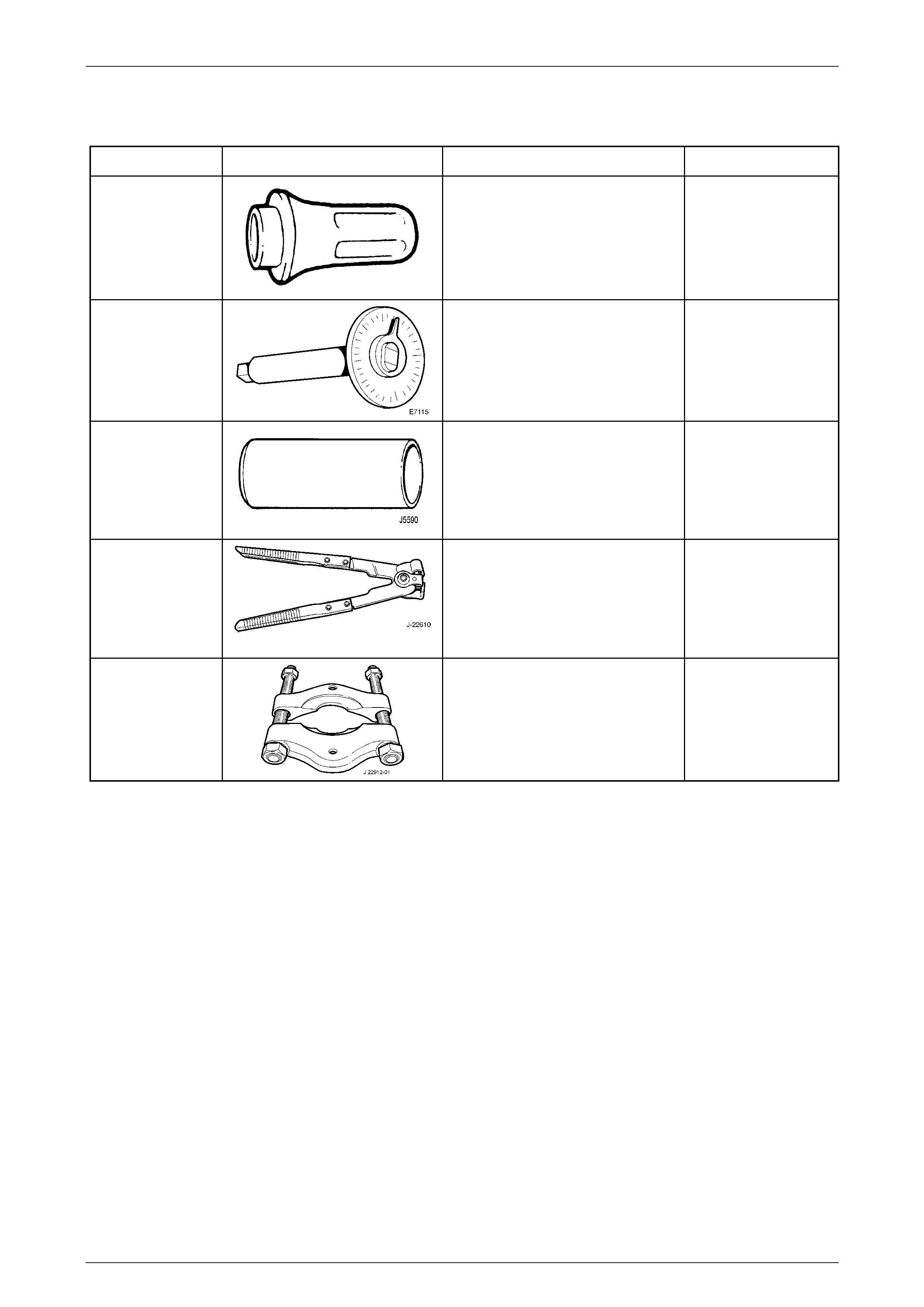
5 Special Tools
Tool Number Illustration Description Tool Classification
J21426
Installer
Used to install the centre bearing and
outer slinger to the rear propeller
shaft.
Previously released.
Unique
E7115
Angle Wrench
Used to tighten fasteners when an
angle torque is specified. Also
released as BT 8653-A
Previously released.
Unique
J5590
Press Tube
Used to install centre bearing slingers.
Previously released.
Unique
J22610
Ke ystone Clamp Pliers
Used to tighten the constant velocity
joint boot clamps. Also released as
E 1896 and 3A13.
Previously released
Desirable
J22912-01
Press Plates
Also released as E6673
Previously released.
Desirable