
Front Propeller Shaft & Univers al Joints Page 4C2–1
Page 4C2–1
Section 4C2
Front Propeller Shaft & Universal Joints
ATTENTION
Before performing any Service Operation or other procedure described in this Section, refer to Section 00
Warnings, Cautions And Notes for correct workshop practices with regard to safety and/or property damage.
1 General Information............................................................................................................................... 2
2 Service Operations................................................................................................................................3
2.1 Propeller Shaft........................................................................................................................................................3
Remove ...................................................................................................................................................................4
Reinstall ..................................................................................................................................................................5
2.2 Fixed Constant Velocity Joint (Front)...................................................................................................................6
2.3 Plunge Constant Velocity Joint (Rear).................................................................................................................7
Remove ...................................................................................................................................................................7
Inspect.....................................................................................................................................................................9
Propeller Shaft and Boot.....................................................................................................................................9
Constant Velocity Joint.......................................................................................................................................9
Reassemble ..........................................................................................................................................................10
Method 1...........................................................................................................................................................10
Method 2...........................................................................................................................................................11
Reinstall ................................................................................................................................................................12
3 Specifications....................................................................................................................................... 14
4 Torque Wrench Specifications........................................................................................................... 15
5 Special Tools........................................................................................................................................ 16
Front Propeller Shaft & Univers al Joints Page 4C2–2
Page 4C2–2
1 General Information
The front propeller shaft assembly fitted to all variants of the MY 2004 AWD Station Wagon models is a single piece
tubular design that incorporates a constant velocity joint at the front and rear of the propeller shaft.
To allow for slight changes in propeller shaft length that may occur from body twist and torque reaction, the rear constant
velocity joint is a plunge type, while the front constant velocity joint is fixed.
Provided the service information contained in this Section is followed, both constant velocity joints are fully serviceable.
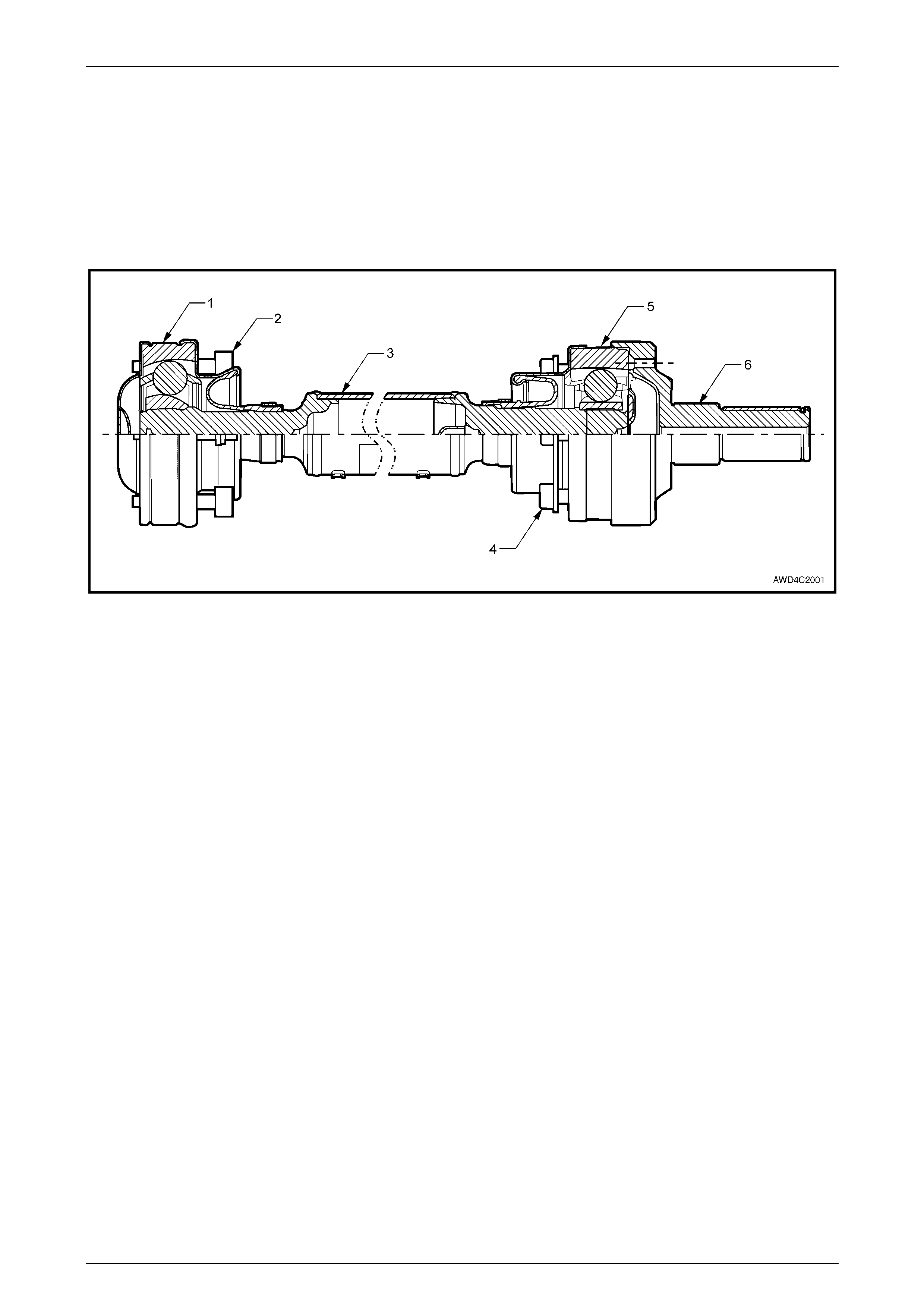
Figure 4C2 – 1 – Front Propeller Shaft Assembly
1 Front Constant Velocity Joint (Fixed Type)
2 Front Constant Velocit y Joint to Front Final Drive Pinion
Flange Bolt (6 Places)
3 Front Propeller Shaft
4 Rear Constant Velocity Joint to Transfer Case Front Output
Flange Bolt (6 Places)
5 Rear Constant Vel ocity Joint (Plunge Type)
6 Transfer Case Front Flange
Front Propeller Shaft & Univers al Joints Page 4C2–3
Page 4C2–3
2 Service Operations
ATTENTION
All fasteners are important attaching parts as they affect the performance of vital components and/or could
result in major repair expense. Where specified in this section, fasteners MUST be replaced w ith parts of the
same part number or an approved equivalent. Do not use fasteners of an inferior quality or substitute design.
Torque values must be used as specified during reassembly to ensure proper retention of all components.
Throughout this section, fastener torque wrench specifications may be accompanied with the following
identification marks:
!
!!
! Fasteners must be replaced after loosening.
"
""
" Vehicle must be at curb height before final tightening.
#
##
# Fasteners either have micro encapsulated sealant applied or incorporate a mechanical thread lock and
should only be re-used once. If in doubt, replacement is recommended.
If one of these identification marks is present alongside a fastener torque wrench specification, the
recommendation regarding that fastener must be adhered to.
2.1 Propeller Shaft
LT Section No. – 05-050
ATTENTION
Fasteners either have micro encapsulated sealant applied or incorporate a mechanical thread lock and
should only be re-used once. If in doubt, replacement is recommended.
#
##
# Propeller shaft front and rear attaching bolts.
As the left side exhaust pipe is close to the
front propeller shaft, it is recommended that
the engine be allowed to cool down before
undertaking this service operation.
Front Propeller Shaft & Univers al Joints Page 4C2–4
Page 4C2–4
Remove
1 Raise the front of the vehicle and support on safety stands. Refer to Section 0A General Information for the location
of jacking and support poin t s.
2 To enable the propeller shaft to be installed in the
original position relative to the front pinion flange, use
a felt tipped pen or similar (e.g. 'whiteout' pen) to make
an alignment mark ('A') on the two components.
3 W ith the transmission in the ‘Park’ position, loosen
then remove the six Torx headed bolts (1), using a
T50 Torx bit and suitable socket equipment. Then,
remove the three position washers (2) securing the
propeller shaft front constant velocity joint to the front
final drive pinion flange.
4 Remove the catalytic converter bracket, by first
removing the nuts from each side and then the two
bolts securing the brac ket to th e transfer case adaptor
housing. Remove the assembled bracket from the
vehicle and set to one side.
NOTE
By removing the bracket intact, the alignment of
the exhaust system will remain undisturbed.
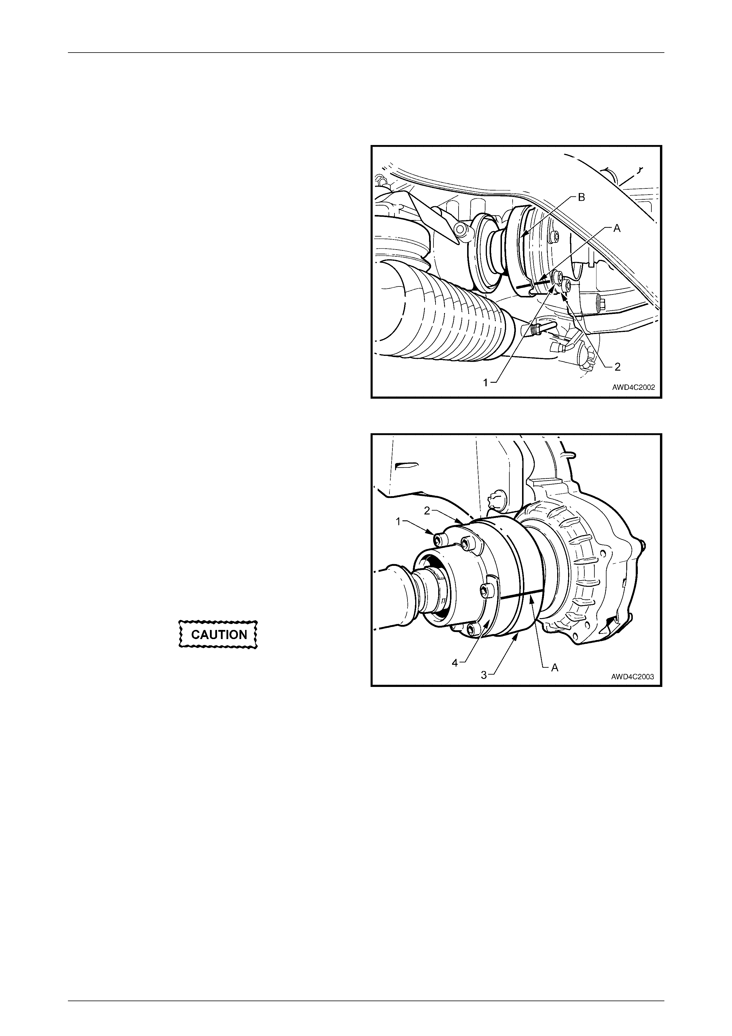
Figure 4C2 – 2
5 Loosen the six Allen key headed screws (1) securing
the rear constant velocity joint (2) to the transfer case
front output flange (3).
6 Release the park brake and select the transmission
Neutral position.
7 After marking the relative position of the rear constant
velocity joint to the transfer case front output flange 'A',
remove the loosened, six Allen key headed screws (1)
and three position washers (4), securing the rear
constant velocity joint (2) to the transfer case, front
output flange (3).
When the front constant velocity joint is
removed from the pinion flange, do not allow
the propeller shaft to hang on the rear
constant velocity joint, as the excessive
angle will most probably damage the boot
and/or the constant velocity joint itself.
Figure 4C2 – 3
8 Rotate the front drive axle pinion flange until one of the three cut-outs are facing downward. Refer to 'B' in
Figure 4C2-2. This is necessary to provide sufficient clearance for propeller shaft removal.
9 Push the front constant velocity joint rearward sufficient to clear the front pinion flange, then lower at the front and
support the propeller shaft.
10 Using a brass drift and hammer, tap the rear constant velocity joint to free the constant velocity joint from the
transfer case front flange. Remove the propeller shaft assembly from the vehicle.

Front Propeller Shaft & Univers al Joints Page 4C2–5
Page 4C2–5
Reinstall
Reinstallation is the reverse of the removal procedure, except for the following items:
1 Use a tap to clean thread sealant from the threads in both the transfer case front flange and the front final drive
pinion flange. Clean any residual thread sealant from all fasteners.
2 Check that the vent hole in the transfer case front flange is clear and not blocked with mud or other debris.
3 Reinstall the rear constant velocity joint to the transfer case front flange, aligning the marks made before removal.
4 Push the front propeller shaft rearwards, enough to allow the reinstallation of the front constant velocity joint to the
final drive pinion flange.
5 Apply Loctite 242 (or equivalent) thread sealant to the threads of the rear constant velocity joint, Allen key headed
retaining bolts before reinstalling, together with the three position washers.
6 After aligning the front constant velocity joint marks, apply Loctite 242 (or equivalent) thread sealant to the bolt
threads, then reinstall, together with the position washers.
7 Select Park and firmly apply the park brake before tightening both the front and rear constant velocity joint retaining
bolts to the correct torque specification.
( # ) Propeller shaft front and rear
constant velocity joint retaining bolts
torque specific atio n ..............................................35 Nm
8 Lower the vehicle to the ground and road test to establish satisfactory vehicle performance.

Front Propeller Shaft & Univers al Joints Page 4C2–6
Page 4C2–6
2.2 Fixed Constant Velocity Joint (Front)
LT Section No. – 05-050
The procedure to remove, inspect, disassemble, reassemble and reinstall this fixed constant velocity joint is the same as
that described in 2.5 Rear Constant Velocity Joint, in Section 4C1 Rear Propeller Shaft & Universal Joints, in the
MY 2004 AWD Wagon Service Information. When reinstalling the constant velocity joint to the propeller shaft however,
the press load must be taken by press plates supporting the propeller shaft under the propeller shaft neck at the plunge
joint end, refer to Figure 4C2-16, in this Section.
Front Propeller Shaft & Univers al Joints Page 4C2–7
Page 4C2–7
2.3 Plunge Constant Velocit y Joint (Rear)
LT Section No. – 05-050
There are two repair kits available for the repair of each constant velocity joint.
a A DUST SHIELD KIT, which contains a cover, dust shield and boot assembly, retaining clamp, circlip and tubes of
grease and sealant (or gasket).
b A CONSTANT VELOCITY JOINT KIT, which contains the same items as in the DUST SHIELD KIT, plus the
constant velocity joint.
Remove
1 Remove front propeller shaft from the vehicle. Refer to 2.1 Propeller Shaft, in this Section.
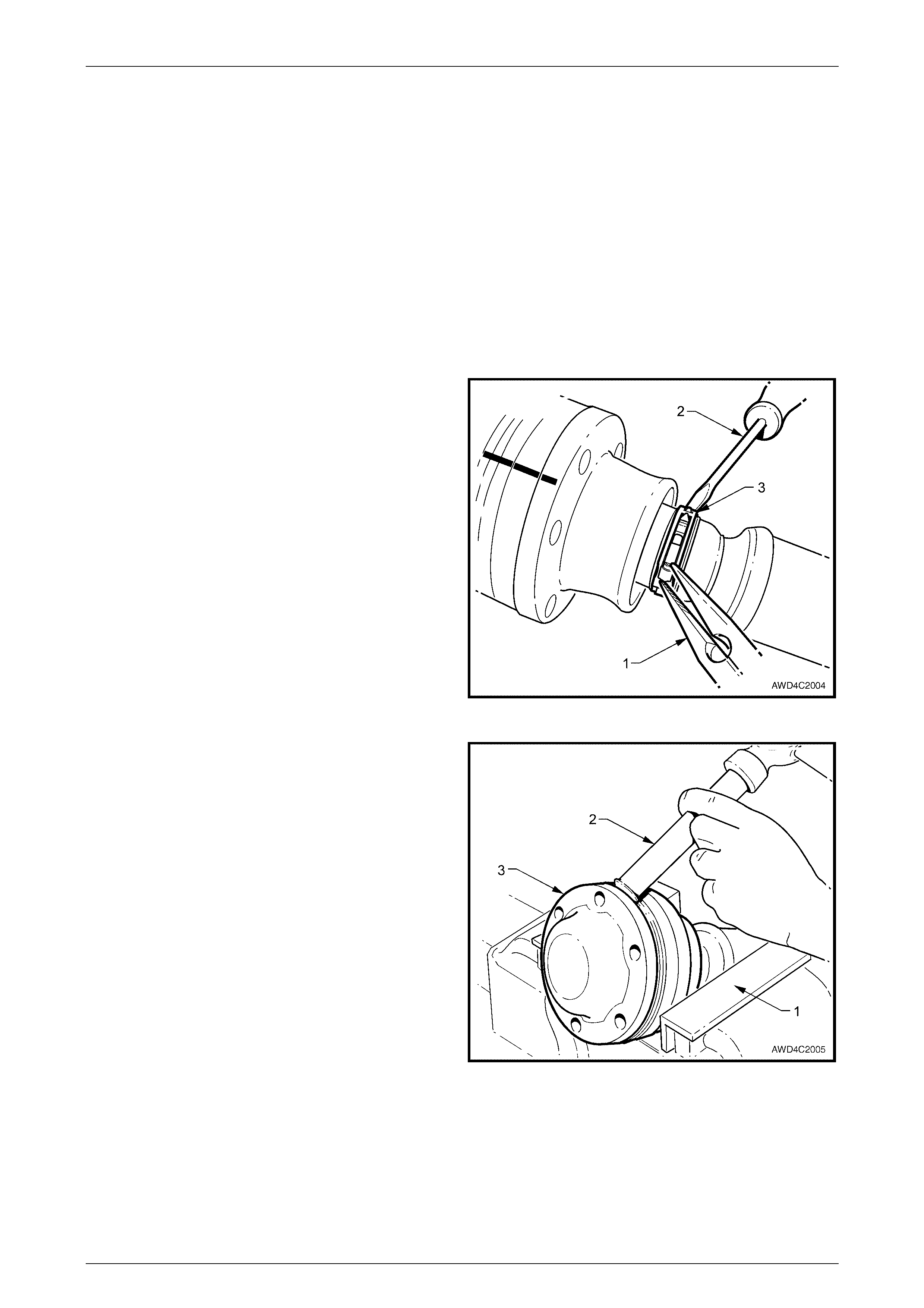
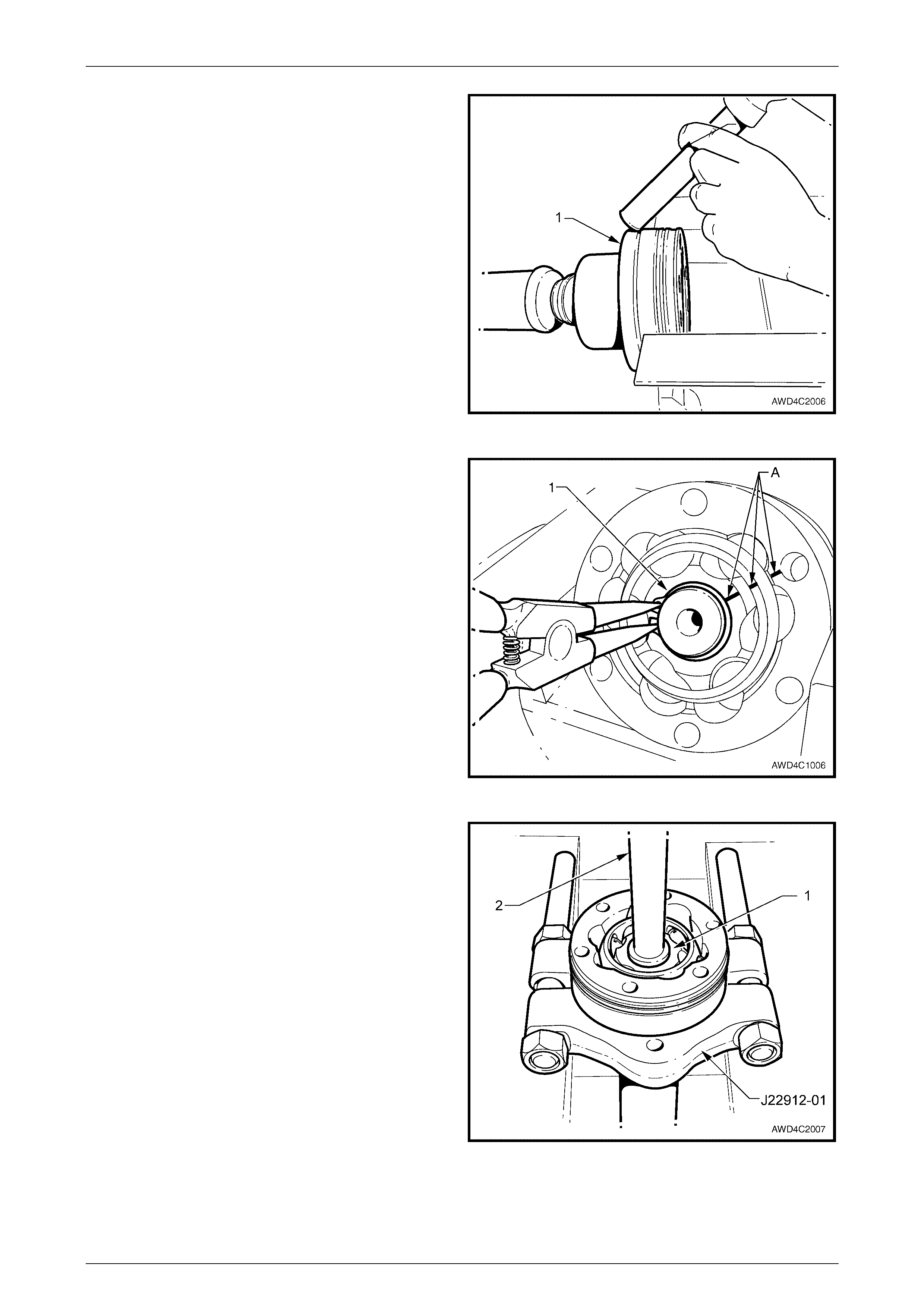
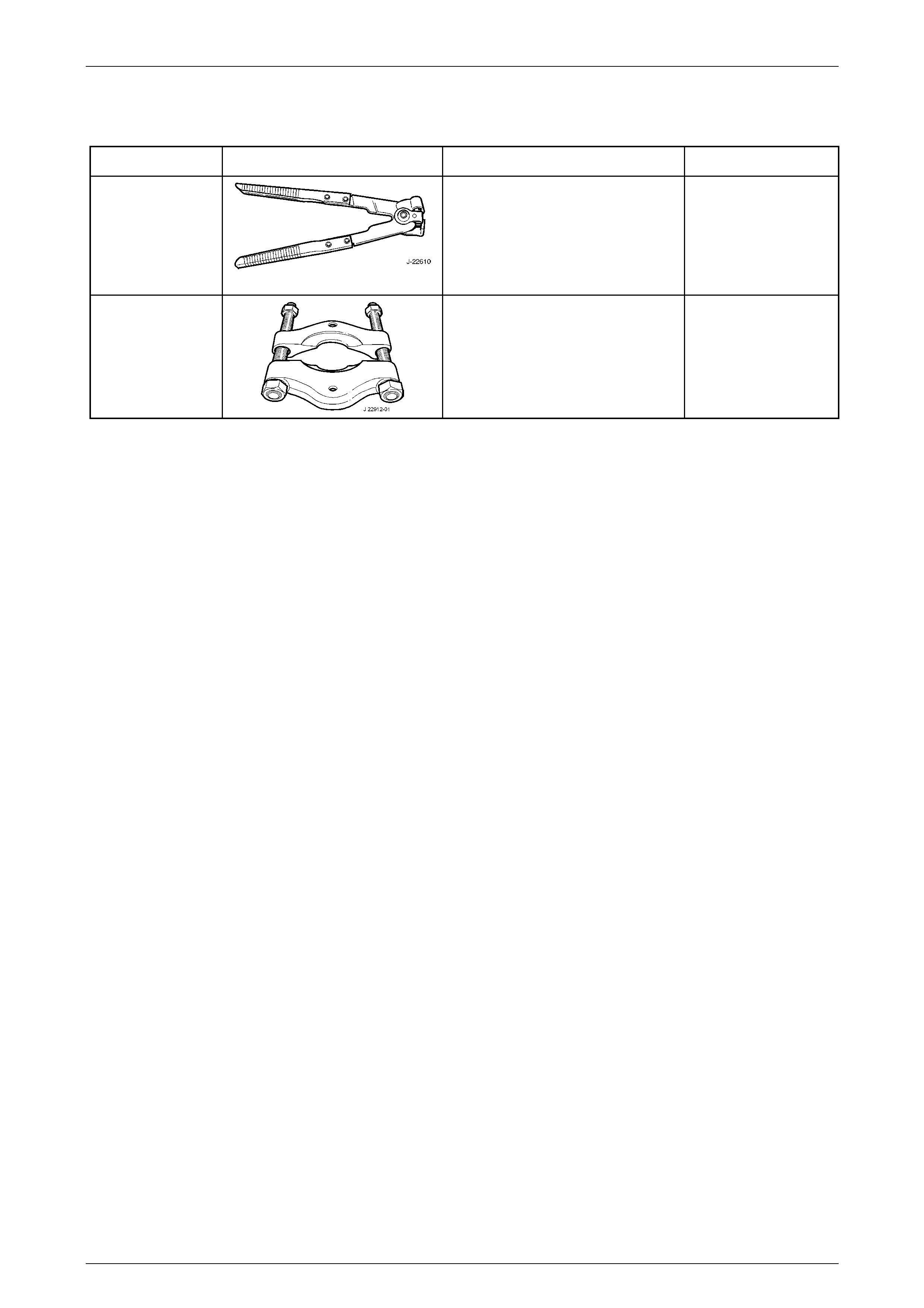
2 W hile tensioning the boot clamp with long nosed pliers
(1), use a small bladed screwdriver (2) to lever the
clamp tang (3) releasing from the clamp barbs.
Remove and discard the clamp.
3 To ensure correct alignment of parts at reassembly,
use a felt tipped pen a (or correction fluid) to mark the
constant velocity joint, the end cover and the dust
shield.
Figure 4C2 – 4
4 Secure the rear constant velocity joint in the soft jaws
(1) of a vice.
5 Using a brass drift (2) and hammer, dislodge, then
remove the dust shield cap (3) from the end of the
constant velocity joint. Discard the removed cover.
Figure 4C2 – 5
Front Propeller Shaft & Univers al Joints Page 4C2–8
Page 4C2–8
6 Reposition the constant velocity joint in the vice jaws
and remove the dust seal and boot assembly (1),
using the same procedure detailed in Step 5.
Figure 4C2 – 6
7 Wipe the excess grease from the end of the constant
velocity joint.
8 Using correction fluid, apply relationship marks on the
inner race, ball cage and outer race, as shown by 'A'.
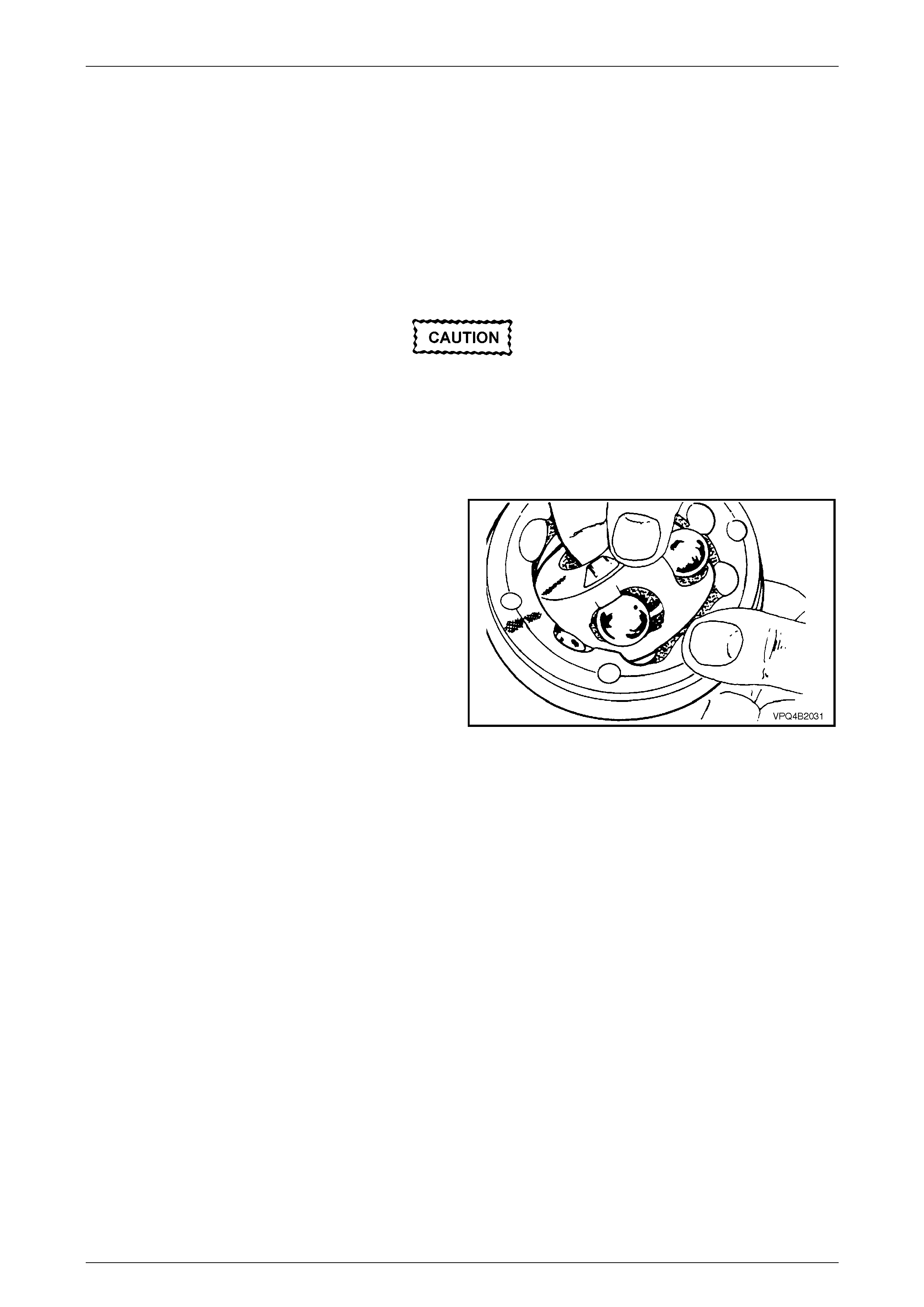
9 Using suitable circlip pliers, remove the circlip (1) from
the end of the propeller shaft and discard.
NOTE
Do not re-use the circlip once it has been
removed. Always fit new parts on reassembly.
10 Slide the dust shield and boot back along the prope ller
shaft.
Figure 4C2 – 7
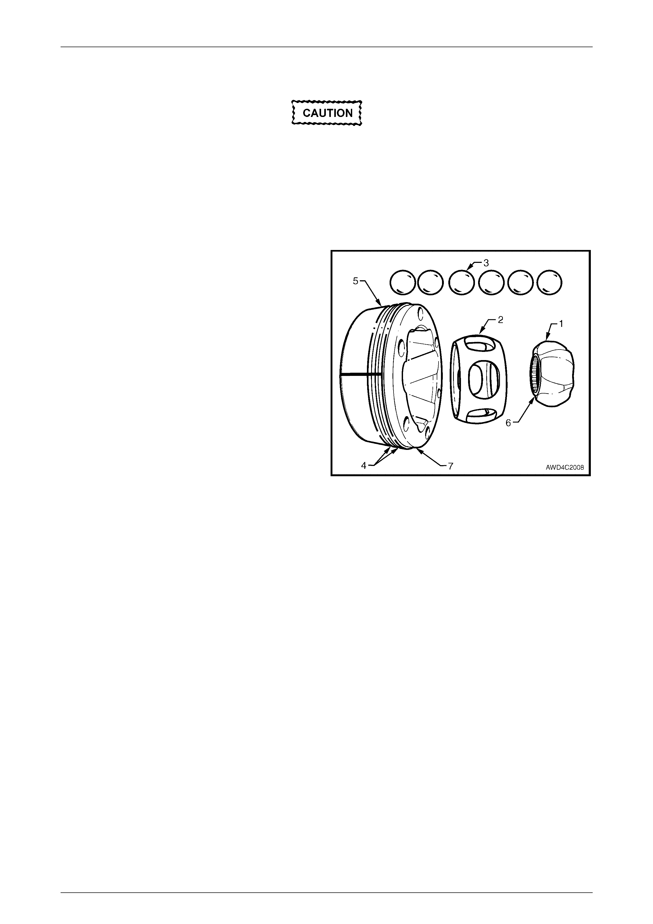
11 Support the constant velocity joint inner race (1) with
suitable press plat es su ch as J 22912-01, then press
the propeller shaft from the constant velocity joint,
using a suitable drift (2).
12 Slide the boot and dust shield from the propeller shaft.
If the boot is to be reinstalled, be careful not to
damage the boot on the propeller shaft splines.
Figure 4C2 – 8
Front Propeller Shaft & Univers al Joints Page 4C2–9
Page 4C2–9
Inspect
Propeller Shaft and Boot
1 Clean propeller shaft splines and boot, using suitable cleaning solvent.
2 Inspect the propeller shaft splines for twisting, cracking or excessive wear. If any of these conditions are observed,
then the propeller shaft must be replaced.
3 Carefully inspect the boot and replace if split, fatigued, cracked or worn.
Constant Velocity Joint
Complete disassembly of the constant
velocity joint is not recommended. The
internal components are a precision fit and
develop their own characteristic wear
patterns. Inter-mixing components could
result in looseness, binding and/or premature
failure of the joint.
4 Inspect grease in joint, and if obviously contaminated
and/or been subjected to dirt ingress, the joint has in
all likelihood suffered damage and should be replaced.
If inspection reveals that the joint has not been
contaminated, clean joint by soaking in a suitable
cleaning solvent.
5 Once grease has been removed, inspect internal
components by tilting inner race to one side to expose
each ball.
NOTE
Take care not to pivot the inner race too sharply,
as the balls can become dislodged. If this does
occur and the original location of the balls is lost,
then the constant velocity joint should be
replaced.
Figure 4C2 – 9
6 Replace joint assembly if there is severe pitting, galling, play between balls and the cage windows, any cracking or
damage to cage, pitting or galling or chips in raceways.
Front Propeller Shaft & Univers al Joints Page 4C2–10
Page 4C2–10
Reassemble
During the removal, cleaning, inspection or
replacement of a constant velocity (constant
velocity) joint, it is possible for the joint to
become disassembled. Should an inadvertent
disassembly of a constant velocity joint
occur, and notwithstanding the earlier
recommendation, it is possible to reassemble
the constant velocity joint, provided the
following procedure is followed EXACTLY.
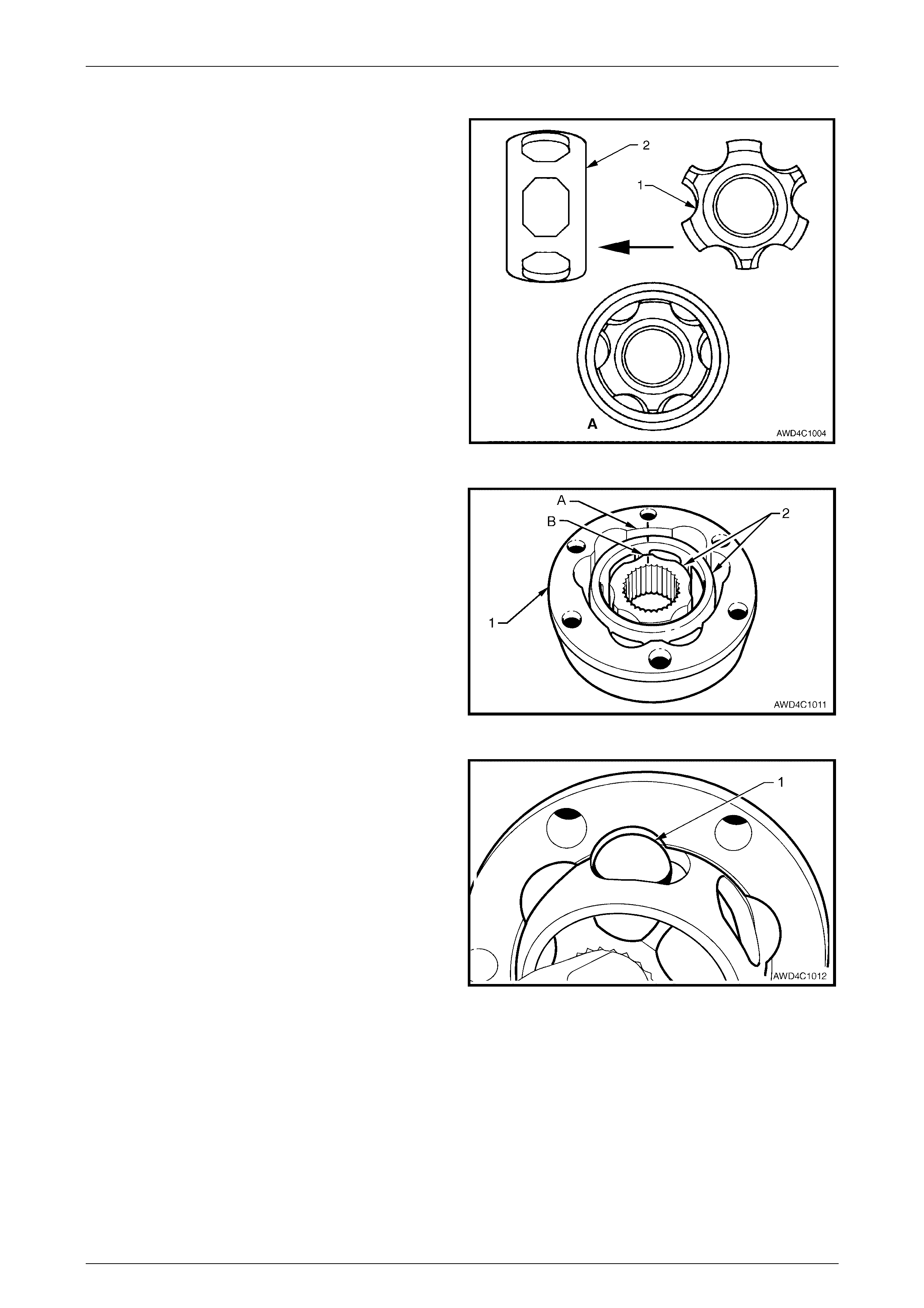
NOTES
• The inner race (1) and cage (2), together with
the individual balls (3), must be maintained in
their original locations to minimise the
creation of a noisy or binding joint.
• As shown in the exploded view of the rear
constant velocity joint, two grooves (4) on the
outer race (5) and the angled ball raceways,
identify this constant velocity joint as a
“plunge” type. Note also the relationship of
the step (6) on the inner race (1) and the
machined recess (7) on the outer race.
• Under no circumstances are components
from one constant velocity joint to be mixed
with components from another constant
velocity joint.
Figure 4C2 – 10
Method 1
1 Provided the balls are held captive in the ball cage when installed, insert each into its correct position.
2 While holding the inner race, cage and the six balls in position, reinstall to the outer race by turning the inner
assembly at 90° to the outer race, reinstall the two balls in their raceways, then rotate the inner assembly, to fully
reinstall. Refer to Figure 4C2-9. Check that the relationship marks are aligned, refer to Figure 4C2-7.
Front Propeller Shaft & Univers al Joints Page 4C2–11
Page 4C2–11
Method 2
1 Place the inner race (1) into the cage (2) and position
centrally within the cage, as shown in view ‘A’.
Figure 4C2 – 11
2 Place the inner race and cage (2) into the outer race
(1).
3 Align the thick sections (A) on the outer race, with the
narrow ones (B) on the inner race. Note also that the
relationship marks are aligned.
Figure 4C2 – 12
4 Tilt the cage and inner race as shown, and fit one ball
(1).
Repeat this process for the remaining five balls.
Figure 4C2 – 13
Front Propeller Shaft & Univers al Joints Page 4C2–12
Page 4C2–12
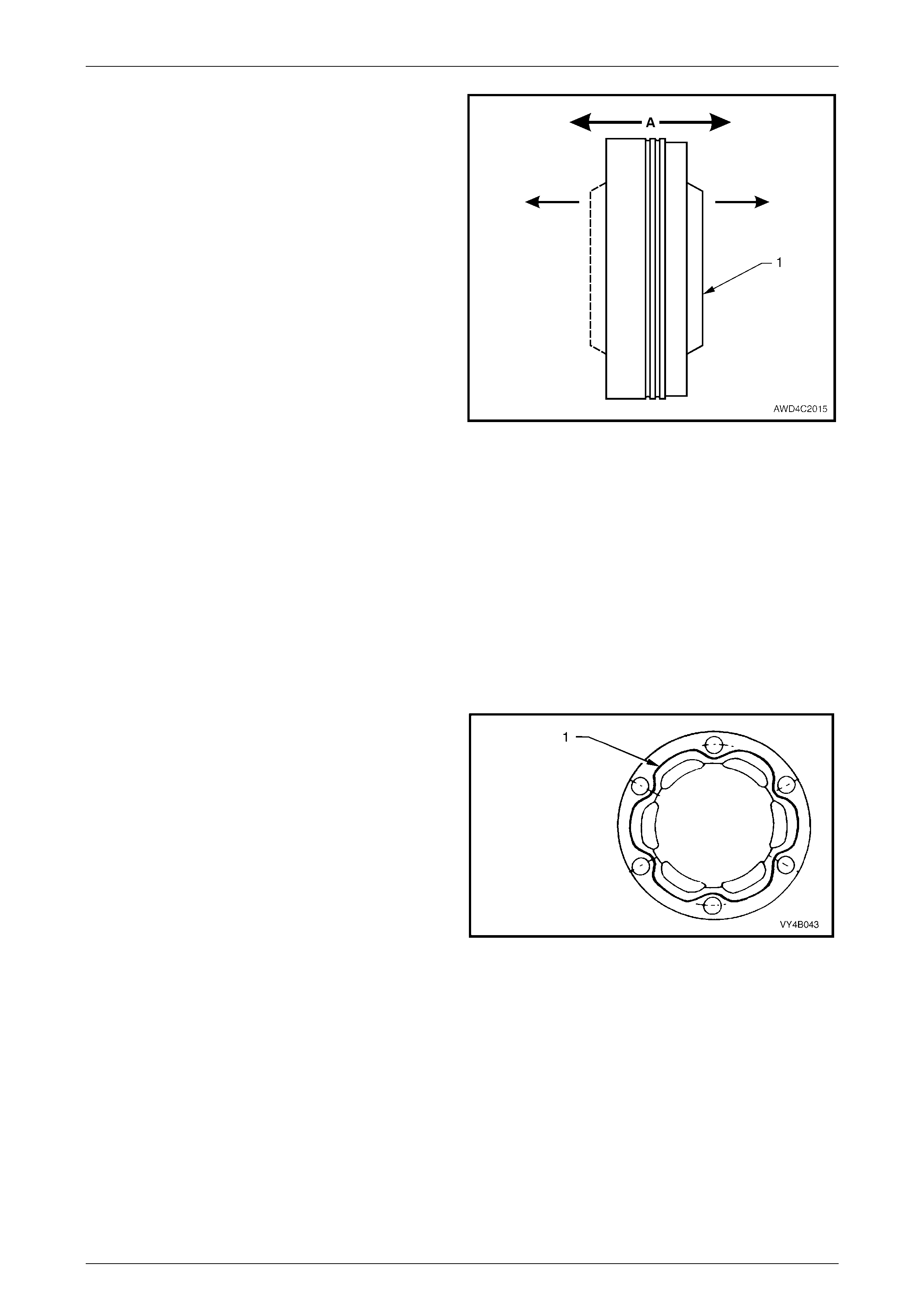
5 W hen assembly of the constant velocity joint is
complete, check for plunge movement of the inner
members (1), indicated by ‘A’. If NO plunge movement
can be achieved, then the constant velocity joint has
NOT been correctly assembled.
If this situation occurs, the constant velocity joint must
be disassembled and the assembly process repeated
until such time that a plunge movement of
approximately 28 mm is achieved.
Figure 4C2 – 14
Reinstall
Reinstallation is the reverse of removal procedure, noting the following points:
1 Cleanliness of con stant velo cit y joint and assoc iate d parts is of prime imp ortance to ensure max imum life of joint
assembly.
2 Install a new boot clamp over the end of the propeller shaft.
3 Inspect dust shield and boot assembly to check that both are undamaged.
4 Pack the constant velocity joint with the lubricant supplied in either of the two available Repair Kits. Work joint by
hand to distribute grease onto all surfaces inside the joint.
5 Clean mating surfaces of constant velocity joint, dust shield and end cap.
6 Apply a 2 mm bead of the sealant supplied in the kit or
use Loctite 510 High Temperature Gasket Eliminator
sealant or equivalent product (Holden's Specification
HN 1593) to the dust shield and boot side of the
constant velocity joint, as shown (1). Take care not to
contaminate the constant velocity joint grease with
sealant.
7 Ensure that the alignment marks made on removal,
are aligned, then use three of the attaching bolts to
align the dust shield with the constant velocity joint,
before tapping the shield into place.
Figure 4C2 – 15
Front Propeller Shaft & Univers al Joints Page 4C2–13
Page 4C2–13
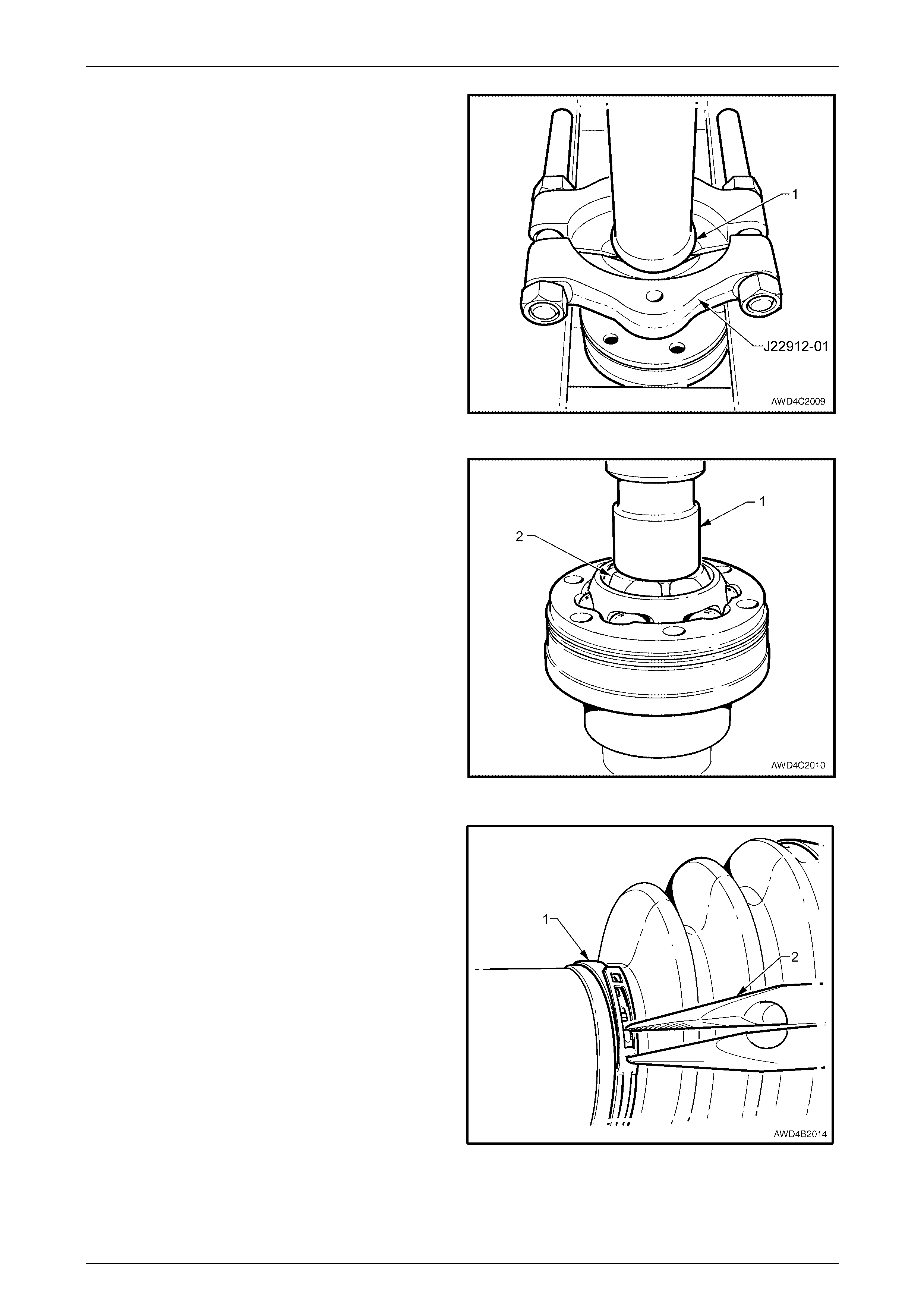
8 Support the front propeller shaft with press plates such
as J22912-01 under the front neck (1), in a position
where the propeller shaft takes the press load and not
the front fixed constant velocity joint.
Figure 4C2 – 16
9 Press constant velocity joint onto shaft using a suitable
size socket or tube (1). Ensure that socket or tube only
presses on inner race (2) of joint.
10 Fit a new circlip to the end of the propeller shaft, using
suitable circlip pliers.
11 Repeat the application of sealant to the end cap side
of the constant velocity joint, refer to step 6 of this
procedure.
12 Again using three of the attaching bolts for alignment,
tap the end cap into place.
Figure 4C2 – 17
13 After locating the boot into the recess in the pr opel ler
shaft, secure with a new clamp (1), tightening with
long nosed pliers (2). Ensure that the end of the clamp
strap engages with the last two barbs.
Figure 4C2 – 18
14 Reinstall propeller shaft. Refer to 2.1 Propeller Shaft in this Section.

Front Propeller Shaft & Univers al Joints Page 4C2–14
Page 4C2–14
3 Specifications
Propeller Shaft
Length (Centre to Centre of each constant velocity Joint, in mid-plunge)................... 666 mm
Propeller Shaft Tube Diameter ................................................................................. 44.50 mm
Constant Velocity Joints
Front (Fixed Design) – Number of Balls................................................................................. 6
Rear (Plunge Design) – Number of Balls............................................................................... 6
Rear Constant Velocity Joint Maximum Plunge Distance (from a central position).... ± 14 mm
Lubrication Quantity
Front Fixed Constant Velocity Joint.................................................................... 29 ± 2.5 gram
Rear Plunge Constant Velocity Joint.................................................................. 45 ± 2.5 gram

Front Propeller Shaft & Univers al Joints Page 4C2–15
Page 4C2–15
4 Torque Wrench Specifications
ATTENTION
!
!!
! Fasteners must be replaced after loosening.
"
""
" Vehicle must be at curb height before final tightening.
#
##
# Fasteners either have micro encapsulated sealant applied or incorporate a mechanical thread lock and
should only be re-used once. If in doubt, replacement is recommended.
# Rear Constant Velocity Joint to Transfer Case Front Flange Bolt ...................35 Nm
# Propeller Shaft Front Constant Velocity Joint to Front Final Drive
Pinion Flange Bolt ...........................................................................................35 Nm
Front Propeller Shaft & Univers al Joints Page 4C2–16
Page 4C2–16
5 Special Tools
Tool Number Illustration Description Tool Classification
J22610
Ke ystone Clamp Pliers
Used to tighten the constant velocity
joint boot clamps. Also released as E
1896 and 3A13.
Previously released
Desirable
J22912-01
Press Plates
Also released as E6 673
Previously released.
Desirable