
Service and Park B raki ng Syst em Page 5A–1
Page 5A–1
Section 5A
Service and Park Braking System
ATTENTION
Before performing any service operation or other procedure described in this Section, refer to Section 00
Warnings, Cautions and Notes for correct workshop practices with regard to safety and/or property damage.
1 General Information............................................................................................................................... 2
1.1 General Description ...............................................................................................................................................3
Master Cylinder ......................................................................................................................................................3
Construction .......................................................................................................................................................3
Operation............................................................................................................................................................5
2 Service Operations................................................................................................................................ 9
2.1 Front Brake Disc.....................................................................................................................................................9
Remove ...................................................................................................................................................................9
Inspection .............................................................................................................................................................10
Brake Disc and Hub Indexing..............................................................................................................................10
Front Hub Runout Check..................................................................................................................................10
Reinstall ................................................................................................................................................................11
2.2 Front Brake Disc Shield.......................................................................................................................................12
Remove .................................................................................................................................................................12
Reinstall ................................................................................................................................................................12
2.3 Pressure Differential Warning Switch ................................................................................................................13
Remove .................................................................................................................................................................13
Test........................................................................................................................................................................13
Reinstall ................................................................................................................................................................14
2.4 Master Cylinder ....................................................................................................................................................15
Remove .................................................................................................................................................................15
Disassemble.....................................................................................................................................................15
Clean and Inspect.................................................................................................................................................17
Reassemble......................................................................................................................................................18
Reinstall ................................................................................................................................................................23
2.5 Brake Booster.......................................................................................................................................................24
3 Specifications....................................................................................................................................... 25
Brake Fluid............................................................................................................................................................25
Master Cylinder ....................................................................................................................................................25
Front Disc..............................................................................................................................................................25
Booster..................................................................................................................................................................25
4 Torque Wrench Specifications........................................................................................................... 26
Techline
Service and Park B raki ng Syst em Page 5A–2
Page 5A–2
1 General Information
With the following exceptions, MY 2004 VY AWD Wagon Service and Park Brake System service information carries
over from MY 2004 VY Series vehicles.
• Front brake disc
• Front brake disc shield
• Master cylinder
• Brake booster
When referring to the MY 2004 VY and V2 Series Service Information, some illustrations may show components that are
different in appearance to the AWD wagon vehicle application. Where differences in the service procedures apply, the
relevant information relating to those differences are covered in this Section.
The front bearing and ABS sensor assembly are unique and includes a new front brake disc with a revised offset due to
the increase in the front track. Front disc diameter has been increased from 298mm to 302mm. The AWD Wagon are
new and have a unique composition of materials.
The front hub is splined to accommodate the front drive shaft. For optimum performance of the front braking system
it is imperative that the front drive shaft is fitted correctly and tightened to the correct torque specification, refer to
Section 4B Final Drive and Drive Shafts.
To accommodate the higher ride height and slightly wider track, some brake hoses and pipes are slightly longer,
however, the service procedures carry over from MY 2004 VY Series vehicles, refer to Section 5A Service and Park
Brake Systems in the MY 2004 VY and V2 Series Service Information.
A new ABS/TCS modulator assembly and a unique brake booster and master cylinder with larger diameter brake
pipes to suit the ABS/TCS modulator are fitted to all vehicles. For ABS/TCS service information, refer to
Section 5B AWD ABS/TCS.
For service information not contained in this Section, refer to Section 5A Service and Park Brake System in the MY 2004
VY and V2 Series Service Information.
Although the master cylinder and booster
appear similar to other variants available, they
are unique to the MY 2004 VY AWD Wagon
Series and must not be substituted or
interchanged with an y other model types.
The organic non-asbestos friction material
composition for the front brake pads is
unique to the AWD Wagon and although
similar in appearance to other models, must
not be substituted or interchanged with any
other model types. While Holden's brake
friction parts are not asbestos based in their
material composition, a danger exists that
non-genuine replacement parts may have
been installed and may contain asbestos.
In the interests of personal safety and for the safe and reliable operation of the braking system, only genuine parts
sh ould be us ed for replac ement purposes.
Service and Park B raki ng Syst em Page 5A–3
Page 5A–3
When servicing the service and park brake
system, do not create dust by grinding or
sanding brake linings, or by cleaning wheel
brake parts with a dry brush or with
compressed air. Breathing in dust that may
contain asbestos fibres can cause serious
bodily harm over a protracted period of time.
A water dampened cloth or water based solution should be used to remove any dust on brake parts. Equipment is
commercially available to perform this washing function. These wet methods prevent brake component fibres from
becoming airborne.
1.1 General Description
Master Cylinder
The primary piston of the AWD Wagon master
cylinder has a deeper push rod recess than
the 2WD master cylinder. This master c ylinder
cannot be fitted to a 2WD Vehicle.
A unique master cylinder is fitted to MY 2004 VY AWD wagon vehicles, which features a tandem centre valve design and
a fast fill valve in the primary circuit. The fast fill valve allows large displacements of fluid to the calipers at the beginning
of brake pedal movement. This in turn, provides reduced brake pedal travel. The master cylinder is mounted to the
vacuum brake booster, which is mounted to the engine side of the dash panel.
Brake pipe diameter for the front primary pipe has been increased from 4.75mm to 6.35mm due to the new AWD
Traction Control System. The pipe fitting for the primary front and the rear brake pipes are both 12mm at the master
cylinder.
A brake fail warning switch is mounted in the cylinder body and incorporates a spring-loaded plunger, which locates into
a tapered groove in the centre of the spool of the pressure differential valve. W hen both front and rear brakes operate,
the spool is in a centralised position and the switch contacts remain open.
Should there be a loss of pressure in either front or rear brake system, when the brake pedal is applied, the spool will
move off centre, closing the switch contacts and turning on the warning icon on the instrument panel.
After repairs have been made and the brake system bled, when the brakes are applied the pressure in both front and
rear systems will equalise, centralizing the spool and opening the switch contacts, thus turning off the warning icon.
Construction
The tandem master cylinder provides separate hydraulic circuits for the application of the brakes in a front to rear split
arrangement. Both of these circuits are fed by a separate fluid feed through a common fluid reservoir, sealed by a
diaphragm fitted inside the reservoir cap. This diaphragm provides an effective seal against any atmospheric moisture
coming into contact with the hygroscopic brake fluid. This provision helps to maintain the brake fluid's boiling point, for a
maximum period of time.
Refer to Figure 5A – 1 and the accompanying table for a complete breakdown of the master cylinder assembly.
Service and Park B raki ng Syst em Page 5A–4
Page 5A–4
Figure 5A – 1
Legend
1 Reservoir Cap
2 Reservoir Cap Diaphragm
3 Reservoir
4 Reservoir Att aching Screw
5 Reservoir Seal i ng Grommets
6 Fast Fill Valve Circlip
7 Fast Fill Valve
8 Fast Fill Valve O-ring
9 Master Cylinder Body
10 Secondary S pri ng (Seven Coils)
11 Spring Retainer
12 Piston Stop Pins, Two Places
13 Secondary Piston
14 Primary S pri ng (Eight Coi ls)
15 Primary Centre Valve, Two Places
16 Primary Piston
17 Primary Pist on O-ri ng
18 End Plug
19 End Plug O-ring
20 Pressure Differential Spool
21 Spool Sleeve O-ring
22 Spool Sleeve
23 Pressure Diff erential Warning Switch
24 Secondary Centre Valve
25 L type, Piston Seal, Three Places
26 Pressure Differential Spool Seals
27 Primary Piston Stop Pin Retaining Plug
28 Primary Piston Stop Pin Retaining Plug
O-ring
29 Primary P ort Blank i ng Pl ug
Service and Park B raki ng Syst em Page 5A–5
Page 5A–5
Operation
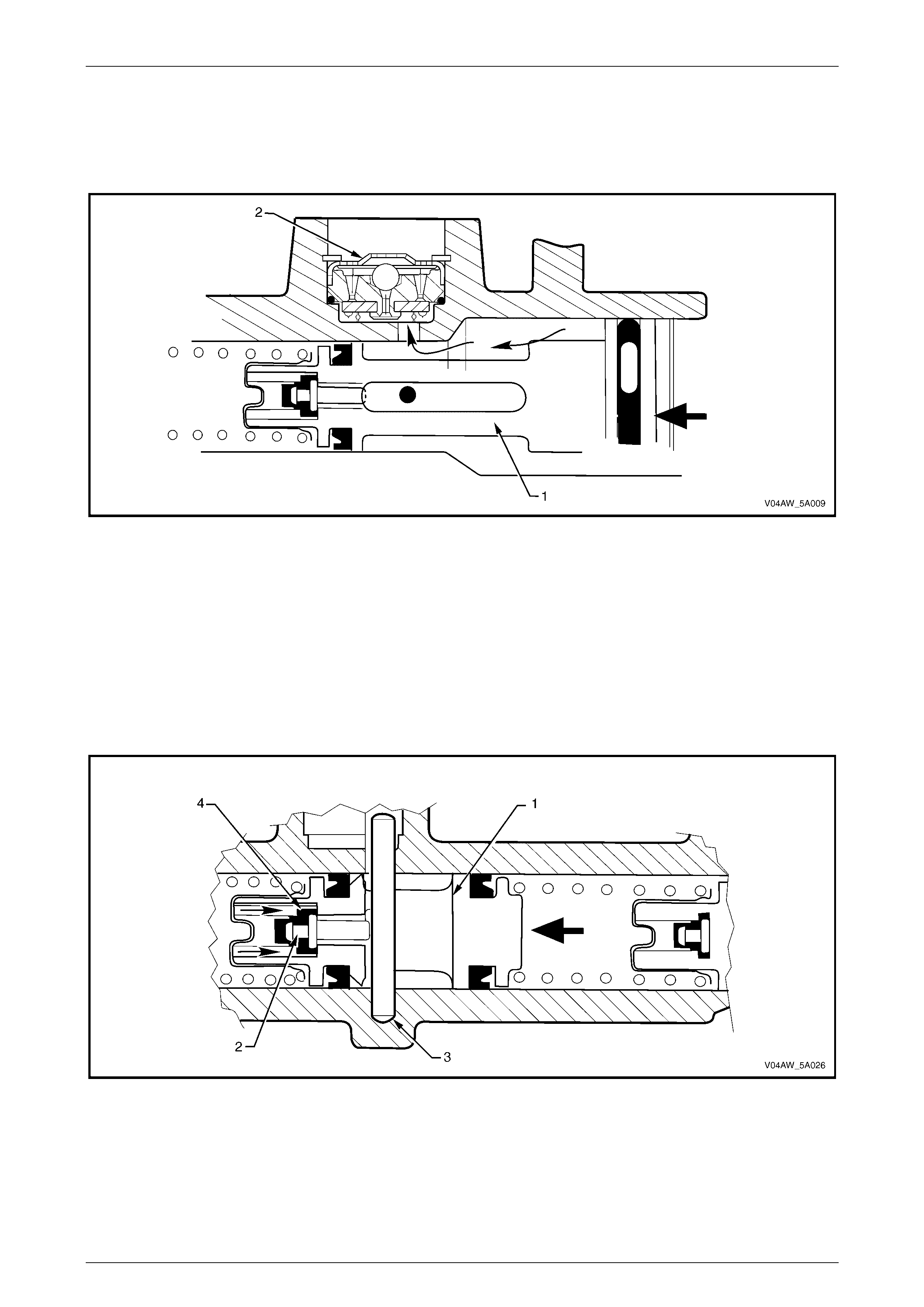
Fast Fill Valve
The “fast fill” (fast pressure build up) valve reduces initial pedal travel by rapidly displacing the brake fluid into the brake
lines and calipers at the beginning of brake application.
The fast fill valve is located in the primary reservoir port (1)
and is secured by a circlip (2).
In operation, the ball valve (3) retains fluid in the master
cylinder until a pre-set line pressure is reached, after which
all further increases in pressure are exhausted back into the
reservoir by raising the ball valve off the seat, reverting the
operation of the master cylinder to that of a conventional
master cylinder.
Initial primary piston movement produces pressure in the
larger bore of the master cylinder which, forces closed the
flap (4) on the fast fill valve preventing fluid from entering
the reservoir port.
Recuperation is achieved by fluid by-passing through the
compensating passage (5). The compensating passage also
allows fluid to by-pass the valve during the manual bleed
operation.
Figure 5A – 2
Primary Piston – Application
Initial primary piston movement (1) produces pressure in the larger bore of the master cylinder which, forces closed the
flap (2) on the fast fill valve preventing fluid from entering the reservoir port, refer to Figure 5A – 3.
This high volume, low pressure fluid, flows over the primary piston primary L type seal (3) and into the smaller bore and
out to the brake calipers, catering for most of the low pressure brake system displacement with minimal primary piston
travel.
This action on the primary piston moving forward, releases the primary centre valve pin (4) from contact with the primary
piston stop pin (5). With the force of the primary centre valve spring, and the release of the primary centre valve pin, the
rubber primary centre valve seal is pushed against the front of the primary piston inner bore, effectively blocking off the
front brake system and preventing the fluid returning back into the large bore of the master cylinder.
Figure 5A – 3
Service and Park B raki ng Syst em Page 5A–6
Page 5A–6
Further primary piston (1) movement increases the pressure in the larger bore and, at a pre-determined pressure, the
ball and seat feature incorporated in the fast fill valve (2) unloads, preventing any additional pressure rise and allowing
fluid to flow from the larger bore into the reservoir port, refer to Figure 5A – 4.
At this point, the small bore section of the master cylinder functions as a conventional master cylinder, producing high
operating line pressures, with minimal primary piston travel.
Figure 5A – 4
Secondary Piston – Application
The combination of hydraulic pressure and the force of the primary piston return spring acting on the secondary piston
(1) causes the secondary piston to move forward. This action on the secondary piston moving forward, releases the
secondary centre valve pin (2) from contact with the secondary piston stop pin (3). With the force of the secondary centre
valve spring, and the release of the secondary centre valve pin, the rubber secondary centre valve seal (4) is pushed
against the front of the secondary piston inner bore, effectively preventing fluid from the rear brake system returning to
the reservoir, refer Figure 5A – 5.
At the same time, the primary centre valve seal is pushed against the front of the primary piston inner bore, effectively
blocking off the fluid from the front brake system returning to the reservoir, producing the high operating fluid pressures.
Figure 5A – 5
Service and Park B raki ng Syst em Page 5A–7
Page 5A–7
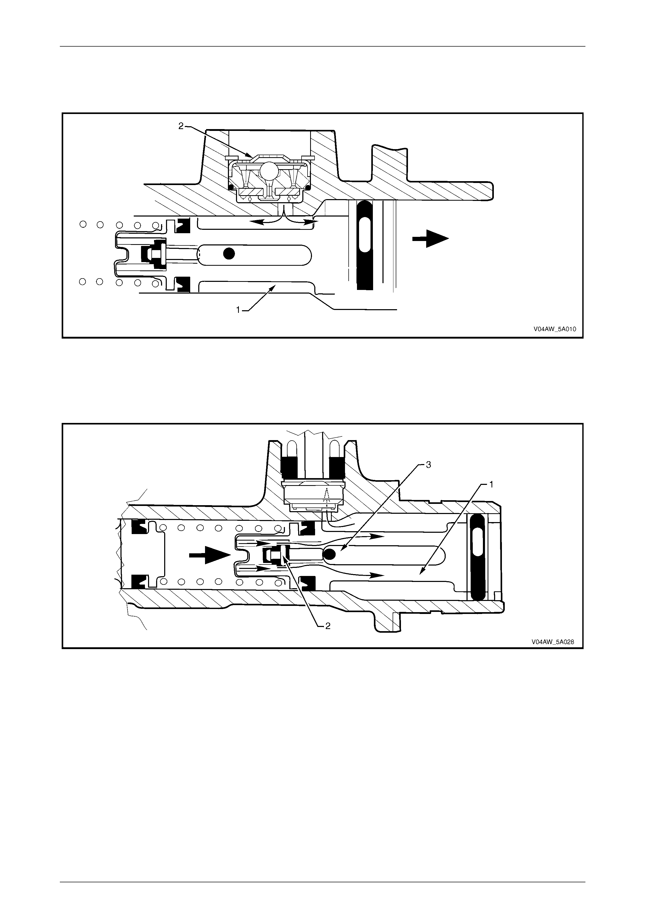
Front Brake System – Release
When the brake pedal is released and the primary piston (1) returns, fluid recuperation will occur from the reservoir port
and through the fast fill valve (2), refer to Figure 5A – 6.
Figure 5A – 6
When the primary piston (1) has fully returned, the primary centre valve pin (2) contacts the primary piston stop pin (3).
At this point the centre valve rubber seal becomes unseated from the primary piston inner bore allowing fluid returning
from the callipers to return to the reservoir via the fast fill valve, thus relieving all pressure in the front brake system, refer
Figure 5A – 7.
Figure 5A – 7
Service and Park B raki ng Syst em Page 5A–8
Page 5A–8
Rear Brake System– Release
When the brake pedal is released and the secondary piston (1) returns, the centre valve pin (2) makes contact with the
secondary piston stop pin (3) causing the secondary centre valve rubber seal (4) to become unseated from the
secondary piston inner bore. This allows fluid returning from the calipers to return to the reservoir, thus relieving all
pressure in the rear brake system, refer Figure 5A – 8.
Figure 5A – 8
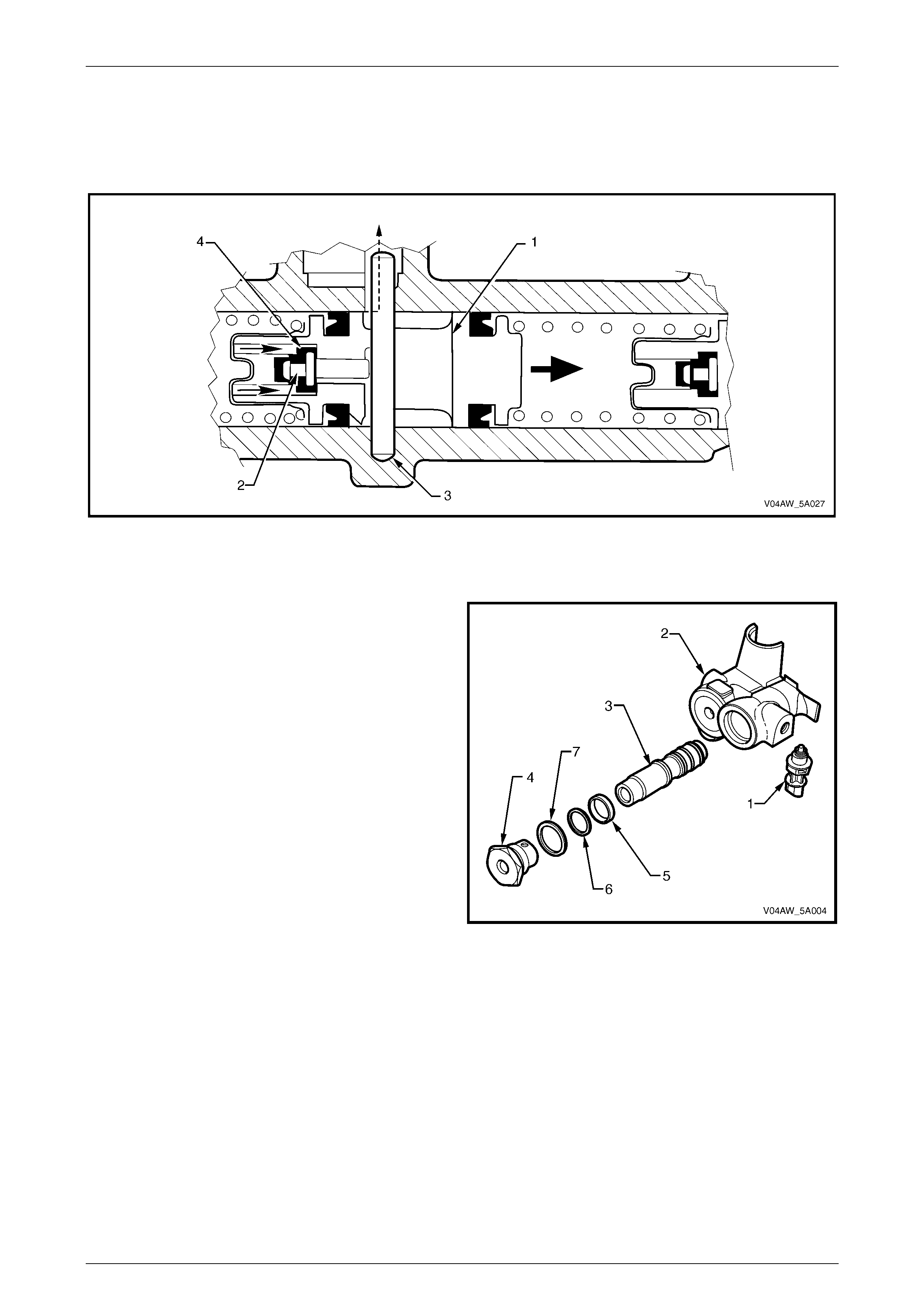
Pressure Differential Switch and Spool
The pressure differential warning switch (1) is mounted into
the master cylinder body (2), with a spring-loaded plunger
fitting into a tapered groove in the centre of the pressure
differenti al spoo l (3).
The pressure differential spool is secured in the master
cylinder pressure differential spool bore with the end
plug (4). Attached to the pressure differential spool is a
spacer (5) and an O-ring (6). The end plug is sealed with an
O-ring (7).
When both front and rear brakes are operated, the pressure
differential spool is in the centralised position with the switch
contacts remaining open.
Should there be a loss of pressure in either the front or rear
brake system when the brake pedal is applied, the pressure
differential spool will move off centre, closing the switch
contacts and turning on the warning icon on the instrument
panel.
After any repairs have been made and the brake system is
bled, when the brakes are app lied the pressure in both the
front and rear systems will equalise and will centralise the
spool, opening the switch contacts, thus turning off the
warning icon.
Figure 5A – 9

Service and Park B raki ng Syst em Page 5A–9
Page 5A–9
2 Service Operations
2.1 Front Brake Disc
LT Section No. – 04-805
Remove
1 Remove the road wheel, refer to Section 10 Wheels and Tyres.
NOTE
The brake disc to hub relationship is carefully
matched during production (indexed) to minimise
the effect of a tolerance stack-up, that could
result in disc runout and subsequent brake
shudder. Therefore, prior to removal of the front
brake disc/s, check to see that a paint daub mark
(1) is still visible on the brake disc hub surface
and an adjacent wheel stud as shown, refer to
Figure 5A – 10.
2 If the paint marks (1) are no longer visible, then prior
to removal, carefully mark the relationship of the brake
disc to the hub, using a felt tipped pen or similar.
NOTE
If this precaution is not taken, then a disc runout
condition could be induced that will cause brake
shudder.
Take care when loosening/tightening the
brake caliper attaching bolts so that the
wheel speed sensor reluctor is not damaged
by the socket equipment used. If damage to
the reluctor does occur, the outer constant
velocity joint must be replaced.
3 Remove the front brake caliper, refer to Section 5A
Service and Park Brake System in the MY 2004 VY
and V2 Series Service Information.
NOTE
It is not necessary to disconnect the brake hose
from the caliper, however, the caliper must be
supported with a wire hook to avoid strain on the
brake hose.
Figure 5A – 10
Service and Park B raki ng Syst em Page 5A–10
Page 5A–10
4 If required, free the brake disc loose by carefully tapping the disc in the centre between the wheel studs with a soft
headed hammer, taking care not to damage the wheel stud threads.
NOTE
If the brake disc centre has rusted and adhered
to the wheel hub, spray with a commercially
available rust penetrating fluid, then jar the brake
disc loose by carefully tapping the disc in the
centre between the wheel studs with a soft faced
hammer or similar, taking care not to damage the
wheel stud threads.
Inspection
If the brake disc surface is rusted or lightly scored, resurface the disc. Scores less than 0.4 mm deep will not affect brake
performance.
If scoring is deep or if brake disc parameters are out of specification, the disc must be machined and/or replaced.
Inspection and machining information carry over from MY 2004 VY Series vehicles. For inspection and machining
information, refer to Section 5A Service and Park Brake System in the MY 2004 VY and V2 Series Service Information.
Brake Disc and Hub Indexing
NOTE
The brake disc and hub indexing procedures
are performed in three stages. Stages one and two carry
over from MY 2004 VY Series vehicles, refer to
Section 5A, Service and Park Braking System in the
MY 2004 VY and V2 Series Service Information. When
completed perform the front hub runout check as follows.
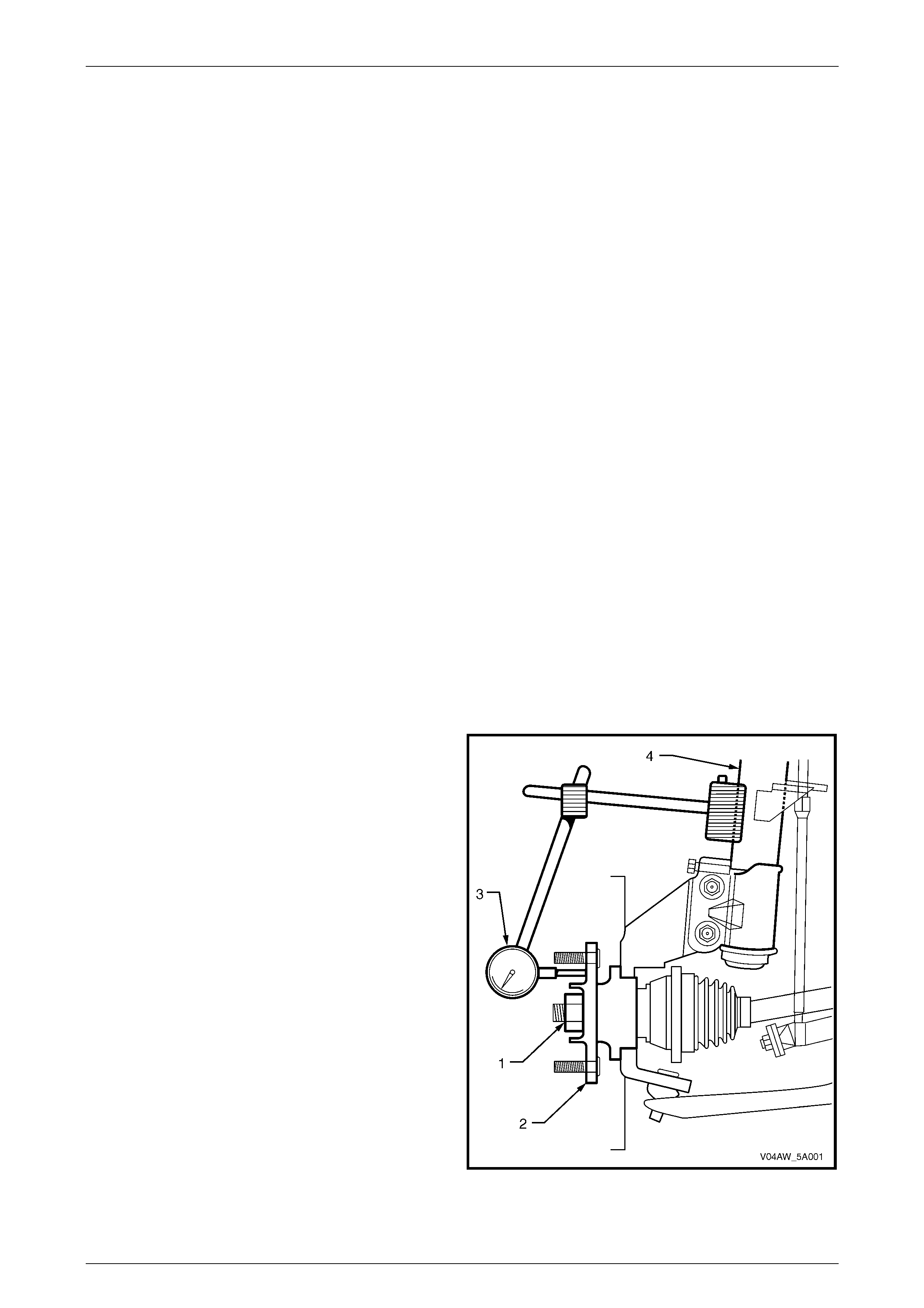
Front Hub Runout Check
1 If required, remove the front brake disc, refer to 2.1 Front B rake Disc.
2 Ensure the front drive shaft is fitted correctly and the
attaching nut (1) is tightened to the correct torque
specification, refer to Section 4B Final Drive and Drive
Shafts.
3 Jack up the front suspension to remove any load from
the front drive shaft.
4. Clean the front hub face (2) by rubbing lightly with fine
emery paper.
5 Locate the dial indicator (3) on the strut tube (4) and
position the pointer on the hub face about midway
between the spigot and the studs.
NOTE
For this check to be performed to 100%
accuracy, a flat paralleled surface plate attached
to the hub should be used, however, measuring
runout between each of the wheel studs should
suffice.
6 Carefully rotate the hub by the hub spigot (to avoid
loading the bearing) and note the points of minimum
and maximum runout on the dial indicator. The
number of divisions between these two points is the
total indicated r unou t.
Figure 5A – 11

Service and Park B raki ng Syst em Page 5A–11
Page 5A–11
7 If the runout measured exceeds 0.025 mm (25 micron) then the hub assembly should be replaced, refer to
Section 5A Service and Park Brake System in the MY 2004 VY and V2 Series Service Information.
8 Following installation, repeat steps, 2 to 6 and mark the minimum point of runout on the hub, and perform stages
one and two of the indexing process, refer to Section 5A Service and Park Brake System in the MY 2004 VY and
V2 Series Service Information.
9 Reinstall the front brake disc, caliper and road wheel, refer to Reinstall in this Section.
Reinstall
Reinstallation of the front brake disc is the reverse of the removal procedure noting the following.
1 Reinstallthe front brake disc over the pre marked indexed position.
2 Reinstall the caliper, refer to Section 5A Service and Park Brake System in the MY 2004 VY and V2 Series Service
Information.
3 Depress the brake pedal several times to bring the brake pads into contact with the disc.
4 Reinstall the road wheel, refer to Section 10 Wheels and Tyres.
Service and Park B raki ng Syst em Page 5A–12
Page 5A–12
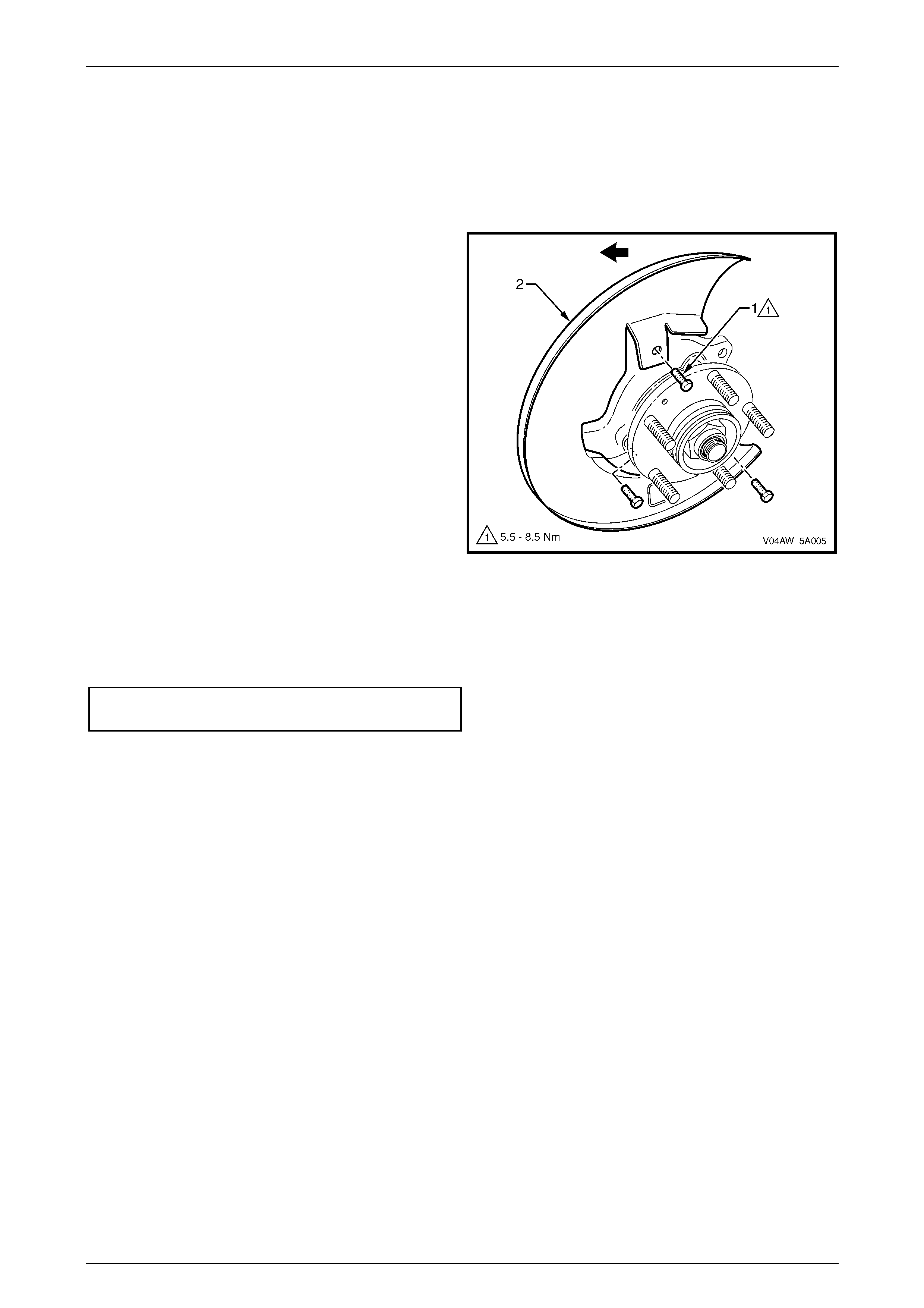
2.2 Front Brake Disc Shield
LT Section 04 – 805
Remove
1 Remove the front brake disc, refer to 2.1 Front Brake
Disc in this Section.
2 Remove the bolt (1), three places, attaching the front
brake disc shield (2), to the front steering knuckle.
3 Remove the front brake disc shield by feeding it
towards the rear of the vehicle.
Figure 5A – 12
Reinstall
Reinstallation of the front brake disc shield is the reverse of the removal procedure. Tighten the attaching bolts to the
correct torque specification.
Front disc brake shield attaching bolt
torque specific atio n .................................... 5.5 – 8.5 Nm
Service and Park B raki ng Syst em Page 5A–13
Page 5A–13
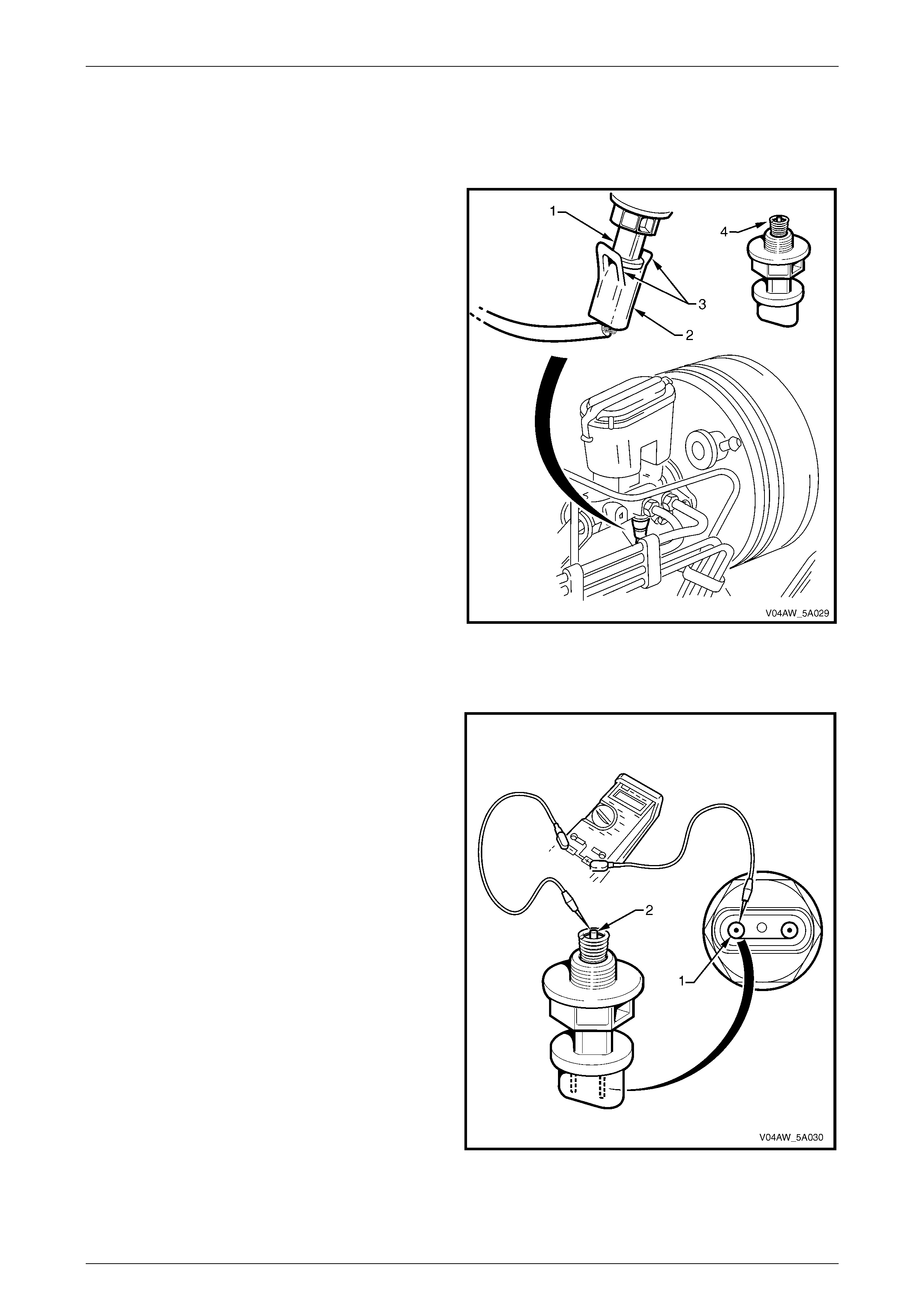
2.3 Pressure Differential Warning Switch
Remove
1 Unclip the pressure differential switch (1) wiring
connector (2) by spreading the tangs (3) apart slightly.
2 Unscrew the pressure differential switch from the
master cylinder and remove, ensuring the earthing
spring (4) is attached to the plunger.
Figure 5A – 13
Test
1 Place a multi meter across the terminal (1) and the
plunger (2).
NOTE
Although there are two terminal connections
within the switch assembly. These terminals are
bridged together by a small bridging wire.
Ensure there is continuity across the terminals.
2 Depress the plunger fully and check for continuity. If
there is no continuity, replace the switch.
Figure 5A – 14
Service and Park B raki ng Syst em Page 5A–14
Page 5A–14
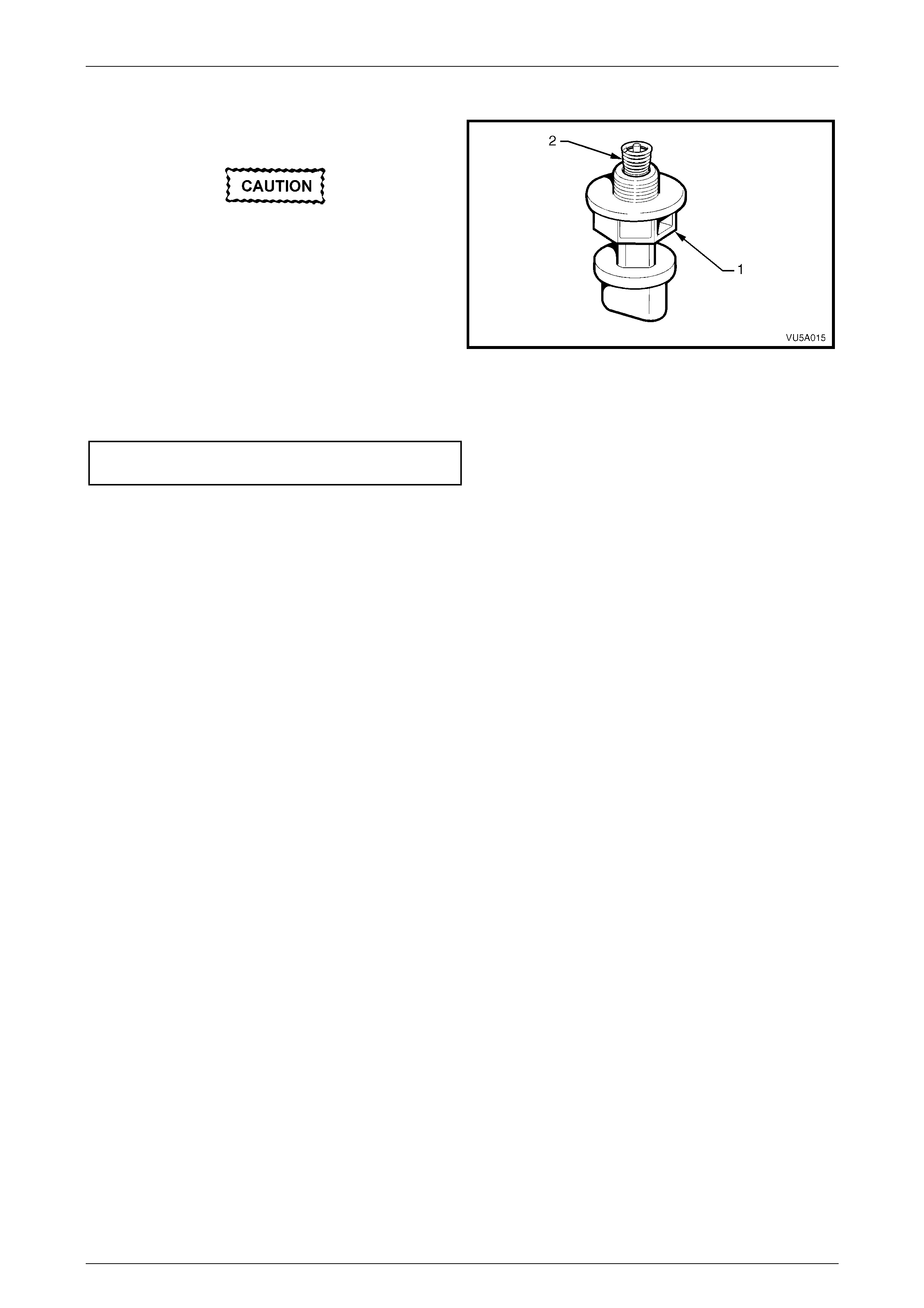
Reinstall
1 Reinstall the pressure differential switch assembly (1)
to the master cylinder body .
Ensure the earthing spring (2) on the
pressure differential switch is installed on the
plunger with the narrow end of the spring
facing the terminal end of the switch. If the
spring is a loose fit, the small end of the
spring may need to be closed down slightly
to give the required attachment. Failure to do
so could result in a faulty earth connection
and failure of the pressure differential
warning light to operate.
2 Tighten the pressure differential switch to the correct
torque specif ication.
Pressure differential switch
torque specific atio n .................................... 1.6 – 2.0 Nm
Figure 5A – 15
Service and Park B raki ng Syst em Page 5A–15
Page 5A–15
2.4 Master Cylinder
LT Section No. 04 – 725
Remove
Brake fluid is extremely damaging to
paintwork. If brake fluid should accidentally
come into contact with a painted surface,
wash the fluid immediately with water and
clean the painted surface.
The removal procedure for the master cylinder fitted to MY 2004 AWD Wagon vehicles carries over from MY 2004 VY
Series vehicles, refer to Section 5A Service and Park Brake System in the MY 2004 VY and V2 Series Service
Information.
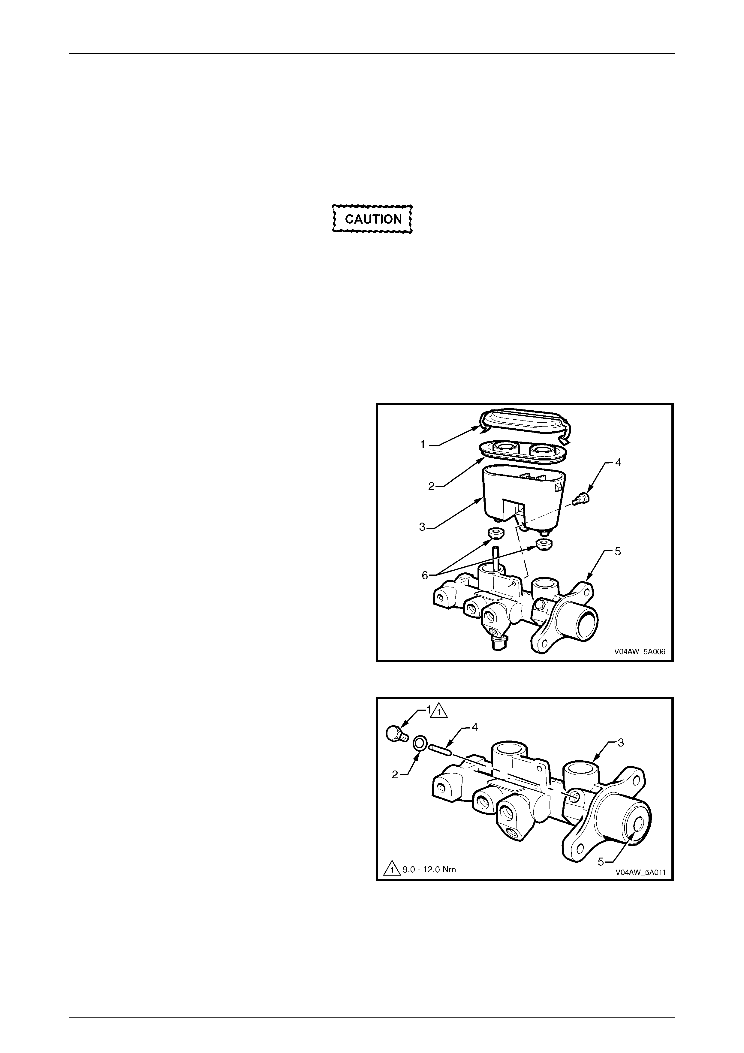
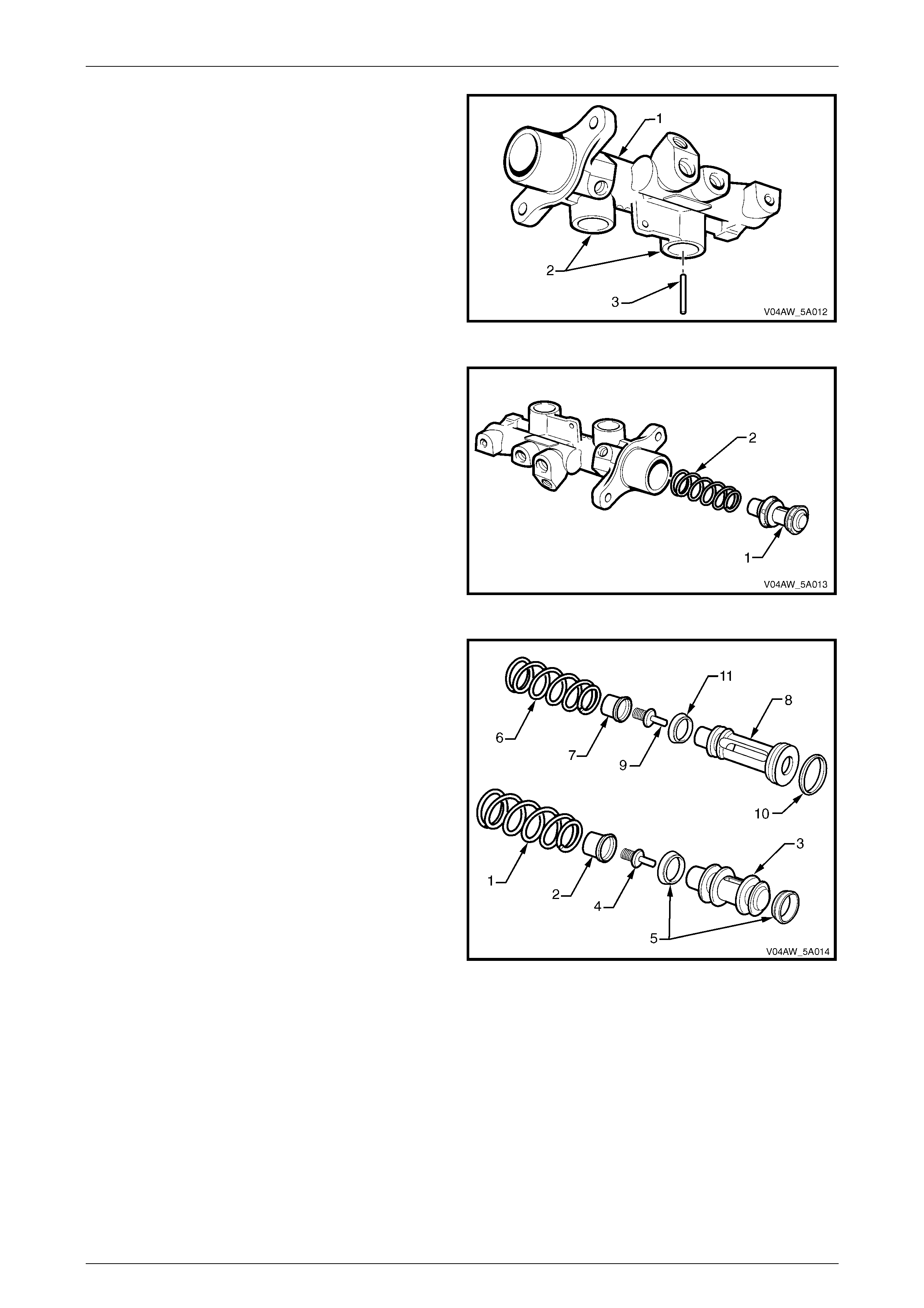
Disassemble
1 Clean the outside of the master cylinder assembly.
2 Remove reservoir cap (1) and diaphragm (2). Discard
any fluid left in plastic reservoir (3).
3 Unscrew the reservoir to body attaching screw (4),
located at the base of the reservoir.
4 Separate the reservoir, by hand, from the master
cylinder body (5), by pulling the reservoir and master
cylinder apart.
5 Remove the two reservoir sealing grommets (6) from
the master cylinder body.
Figure 5A – 16
6 Remove the primary stop pin retaining plug (1) and
O-ring (2).
7 Invert the master cylinder body (3) so that the hole for
the primary stop pin (4) is face down.
8 Depress the primary piston (5) slightly with a wood
dowel or brass rod until the piston moves off the
primary stop pin, allowing the primary stop pin to freely
fall out.
9 Carefully remove the primary piston from the main
bore of the master cylinder.
NOTE
If the primary stop pin doesn't fall out, repeat the
process and using long nose pliers, carefully pull
the pin out.
Figure 5A – 17
Service and Park B raki ng Syst em Page 5A–16
Page 5A–16
10 Invert the master cylinder body (1) so that the
reservoir ports (2) face downwards.
11 Depress the secondary piston, located inside the bore
of the master cylinder with a wood dowel or brass rod
until the piston bottoms in the bore of the master
cylinder body, allowing the secondary stop pin (3) to
freely fall out.
NOTE
If the secondary stop pin doesn't fall out, repeat
the process and using long nose pliers, carefully
pull the pin out.
Figure 5A – 18
12 Remove secondary piston (1) and return spring (2), by
lightly tapping the open end of the master cylinder
bore squarely onto a soft piece of wood.
Figure 5A – 19
13 Remove the secondary spring (1) from the retainer (2)
and remove the retainer from the secondary piston (3).
14 Remove the secondary centre valve and spring (4)
from the secondary piston.
15 Using a small screwdriver, carefully remove the
secondary piston L-type seals (5) from the secondary
piston, taking extreme care not to damage the piston
in the process.
16 Remove the primary spring (6) from the retainer (7)
and remove the retainer from the primary piston (8)
17 Remove the primary centre valve and spring (9) from
the primary piston.
18 Using a small screwdriver, carefully remove the O-ring
seal (10) and the L-type seal (11) from the primary
piston, taking extreme care not to damage the piston
in the process.
Figure 5A – 20
Service and Park B raki ng Syst em Page 5A–17
Page 5A–17
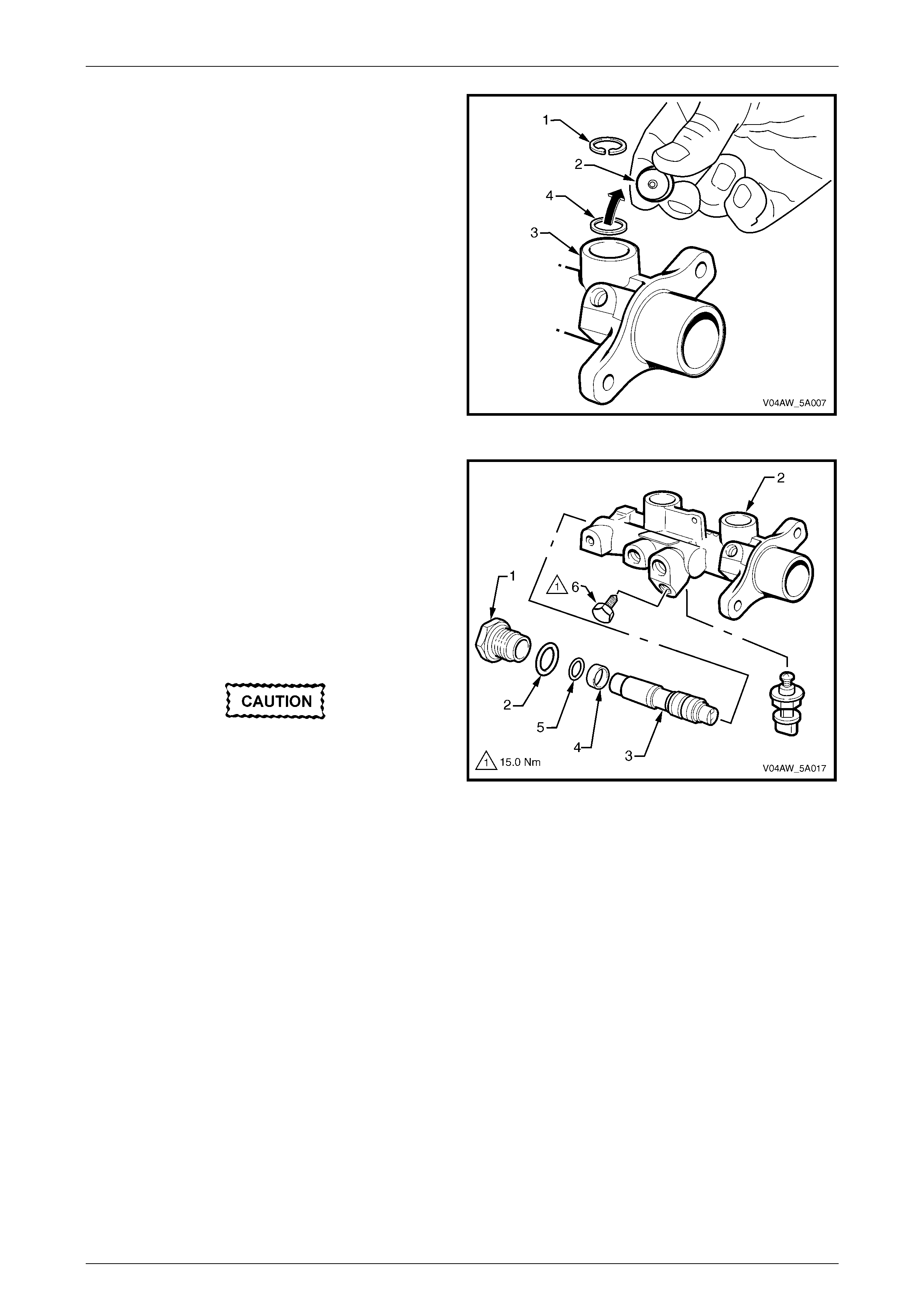
19 Using suitable circlip pliers, remove the circlip (1)
retaining the fast fill valve (2), located in the primary
reservoir port of the master cylinder (3).
20 Face the master cylinder reservoir ports downwards to
allow the fast fill valve to fall out. If the valve is stuck,
lightly tap the master cylinder on a piece of soft wood
to assist removal.
21 Remove the valve sealing O-ring (4) from the bottom
of the reservoir port.
Figure 5A – 21
22 Remove the pressure differential switch, refer to
2.2 Pressure Differential Switch.
23 Unscrew and remove the end plug (1) and O-ring (2)
from the master cylinder,
24 Remove the pressure differential spool assembly (3)
with the spacer (4) and O-ring (5), by lightly tapping
the 'end plug' end of the cylinder bore squarely onto a
soft piece of wood to dislodge the pressure differential
spool assembly.
26 Remove the primary port blanking plug (6).
Do not damage the pressure differential
spool assembly b y attempting to pull it out of
the bore with pliers.
Figure 5A – 22
NOTE
Do not disassemble the pressure differential
spool assembly as this is only serviced as a
complete assembly.
Clean and Inspect
NOTE
Ensure work area is clean and free of dust or
other contaminants. These can affect the
performance of the seals in the master cylinder
and cause premature failure of the master
cylinder.
1 Wash all internal parts, the master cylinder body, reservoir and cap in clean methylated spirits.
2 Check all recesses, openings and passages to ensure they are open and free of any foreign matter.
3 Place all parts on a clean surface.
4 Inspect the master cylinder bores for signs of etching, pitting, scoring or rust. If in poor condition, replace the
master cylinder.
Service and Park B raki ng Syst em Page 5A–18
Page 5A–18
Do not hone the master cylinder bore. If the
master cylinder bore is damaged, the master
cylinder must be replaced.
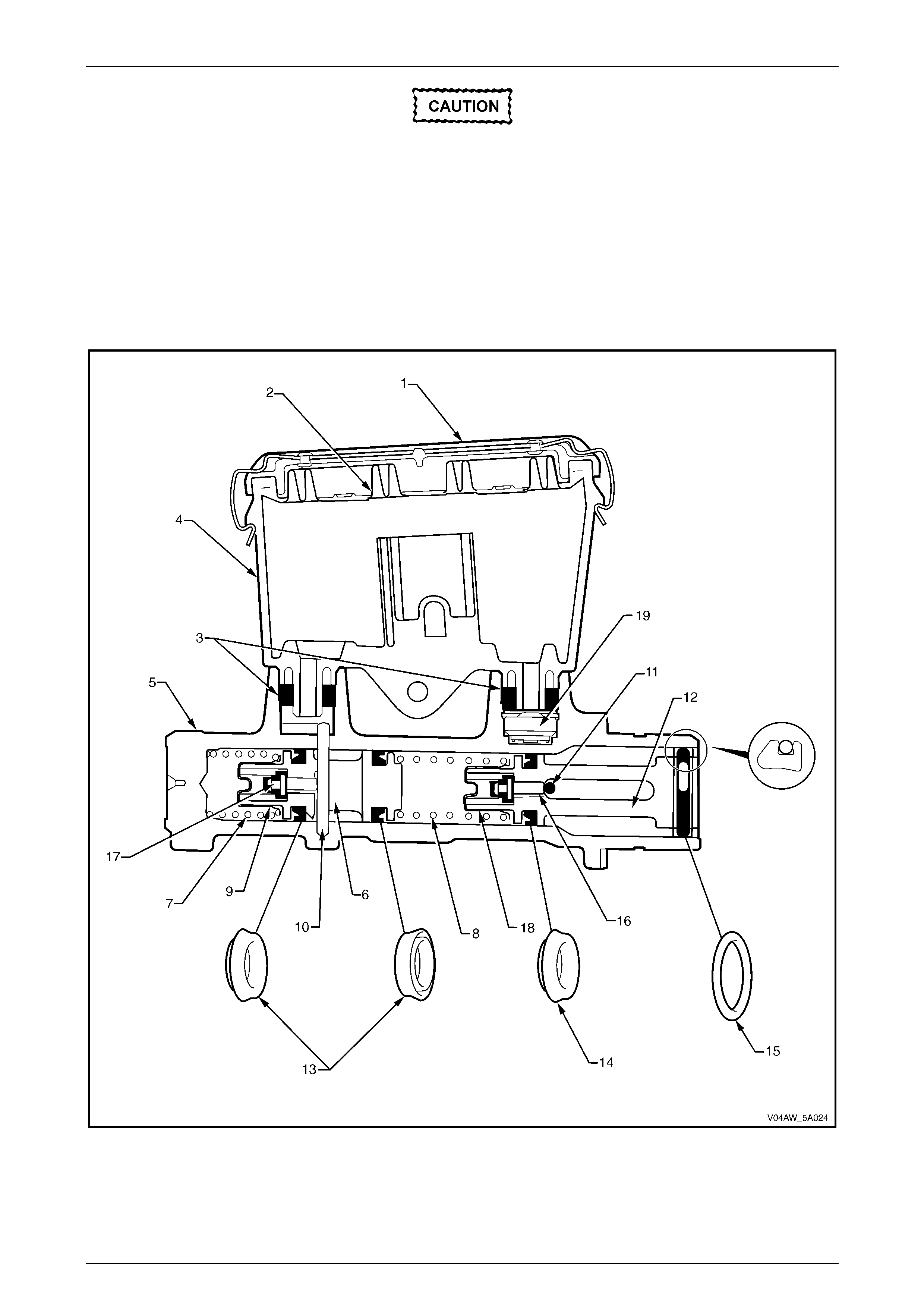
Reassemble
NOTE
The three L-type seals (13 and 14) must be
assembled in the directions and positions shown,
refer Figure 5A – 23
Figure 5A – 23

Service and Park B raki ng Syst em Page 5A–19
Page 5A–19
Legend
1 Reservoir Cap
2 Reservoir Cap Diaphragm
3 Reservoir Seal i ng Grommets
4 Reservoir
5 Master Cylinder Body
6 Secondary Piston
7 Secondary S pri ng (Seven Coils)
8 Primary S pri ng (Eight Coils )
9 Secondary S pri ng Retainer
10 Secondary P iston St op Pin
11 Primary Piston Stop Pin
12 Primary Piston
13 Secondary Seal L-Type
14 Primary Seal L-Type
15 Primary S eal O-ring
16 Primary Centre Valve
17 Secondary Centre Valve
18 Primary S pi ri ng Retai ner
19 Fast Fill Valve
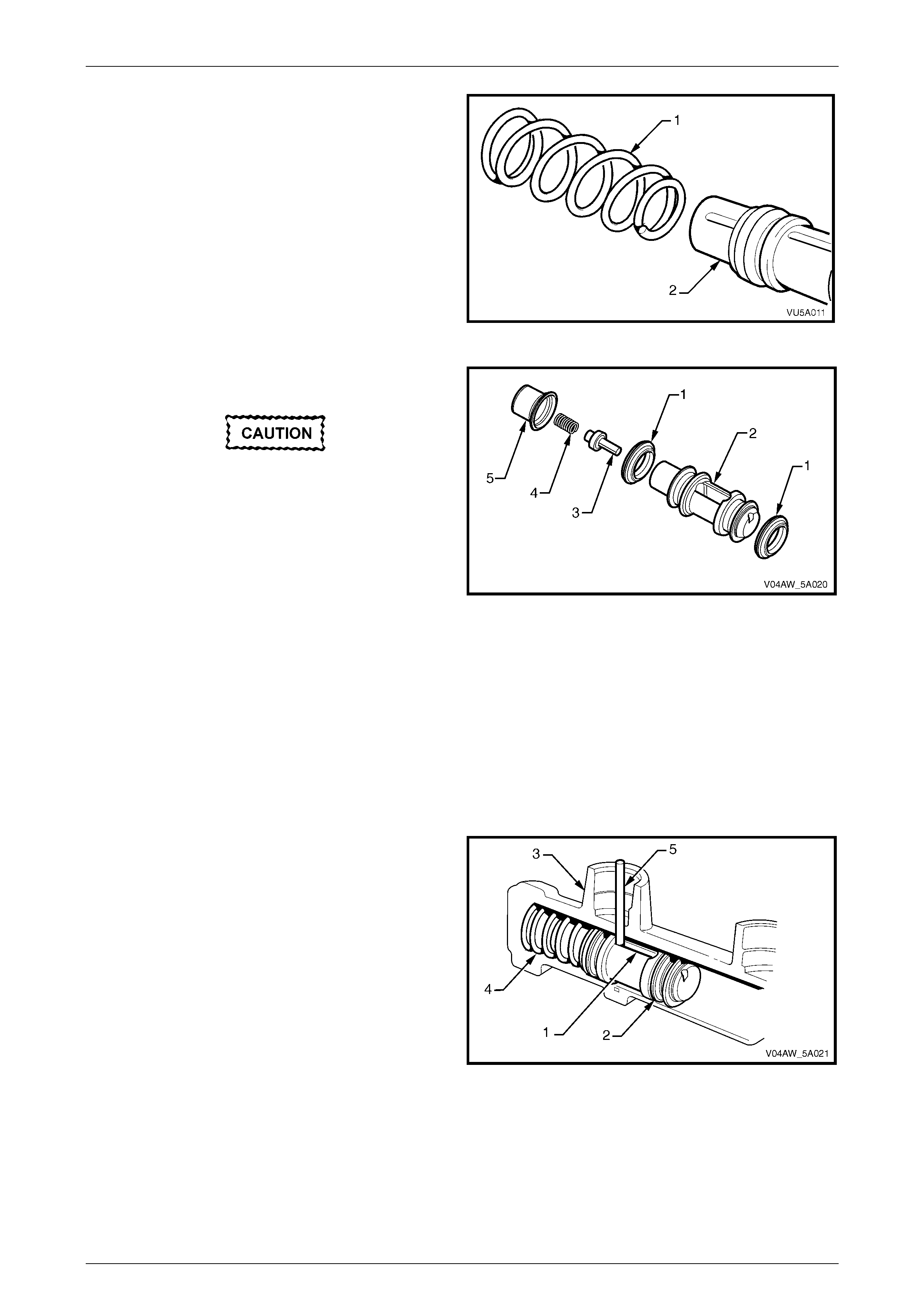
1 Thoroughly wash all internal parts including the master cylinder body and reservoir in methylated spirits and using
compressed air, carefully blow clean the internal parts and the main bore and ports of the body and reservoir prior
to reassembly.
NOTE
Prior to assembling the seals to the pistons,
ensure that the pistons, without seals fitted to
them are free to move the full piston stroke in the
bore.
NOTE
Before assembly, lubricate all internal parts with
clean, recommended brake fluid from a sealed
container.
2 Using a small screwdriver, carefully install the primary
O-ring seal (1) into the groove at the large end of the
primary piston (2).
3 Using a small screwdriver, carefully install the primary
L-type seal (3) into the groove at the small end of the
primary piston.
The sealing face of the seal must face
towards the small end of the primary piston.
4 Insert the rubber end of the primary centre valve (4),
into the small primary centre valve spring (5). Hold the
primary centre valve spring and insert the primary
centre valve into the primary piston inner hole.
5 Push the spring retainer (6), onto the small end of the
primary piston, ensuring the centre valve spring
locates on the centre protrusion of the retainer.
Figure 5A – 24
6 Press the primary spring retainer (1) firmly against the
primary piston (2).
NOTE
If the retainer is loose on the primary piston, use
pliers to slightly crimp the retainer in opposing
directions as shown (3) to provide a firm fit,
taking care not to squash the piston during
crimping.
Figure 5A – 25
Service and Park B raki ng Syst em Page 5A–20
Page 5A–20
7 Assemble the primary return spring (1) over the end of
the primary piston spring retainer (2). This should have
a slight interference fit.
8 Place the primary piston assembly on a clean lint free
cloth to await further assembly.
Figure 5A – 26
9 Using a small screwdriver, caref ully assemble the two
L-type seals (1) to the secondary piston (2).
The sealing face of the seal must face
towards the small end of the primary piston.
10 Insert the rubber end of the secondary centre valve (3)
into the small secondary centre valve spring (4). Hold
the secondary centre valve spring and insert the
secondary centre valve into the secondary piston inner
hole.
11 Push the spring retainer (5) onto the small end of the
second ary piston , ensuring the centre valve spring
locates on the centre protrusion of the retainer.
Figure 5A – 27
12 Press the secondary spring retainer firmly against the secondary piston.
NOTE
If the retainer is loose on the secondary piston,
use pliers to slightly crimp the retainer in
opposing directions (3) to provide a firm fit, taking
care not to squash the piston during crimping,
refer Figure 5A – 25.
13 Align the slot (1) in the secondary piston (2), with the
large hole in the secondary reservoir port (3).
14 Carefully insert the secondary piston, spring first, into
the bore of the master cylinder, until the return spring
(4) 'bottoms'.
NOTE
Ensure the secondary spring does not dislodge
from the secondary piston assembly during this
operation.
15 Fully stroke the secondary piston using a soft dowel
and, while holding the piston at the end of the stroke,
install the se cond ary piston st op pin (5), into the
secondary large hole in the reservoir port.
Figure 5A – 28
NOTE
The piston stop pin should easily fit through the
larger of the two holes located in the secondary
reservoir port. The top of the secondary piston
stop pin should not protrude more than 6mm
above the bottom of the reservoir port.
Service and Park B raki ng Syst em Page 5A–21
Page 5A–21
16 Align the slot (1) in the primary piston (2), with the hole
in the primary piston stop pin port (3).
17 Insert the primary piston and spring assembly into the
main bore against the secondary piston.
Figure 5A – 29
18 Then carefully push the primary piston (1), down the
bore until the primary piston is just below flush with the
bore opening and install the primary piston stop pin
(2).
19 Install the primary piston stop pin retaining plug (3)
and O-ring (4).
20 Tighten the primary piston stop pin retaining plug to
the correct torque specification.
Primary piston stop pin retaining plug
torque specific atio n .................................. 9.0 – 12.0 Nm
21 Ensure movement of the primary piston is free to
move in the bore by carefully stroking the piston and
checking that the primary piston returns to the end of
the bore after each stroke.
Figure 5A – 30
22 Lubricate the O-rings (1) on the pressure differential
spool (2) with clean recommended brake fluid.
23 Ensure the spacer (3) and O-ring (4), are fitted over
the pressure different ial spo ol i n the correct order,
spacer first, then the O-ring.
24 Insert the pressure differential spool into the bore.
Extreme care should be taken when inserting the
pressure differential spool to ensure that the O-rings
(1 and 4) are not damaged If the O-rings are
damaged, the master cy lin der w ill not funct ion
correctly and will leak brake fluid. The pressure
differential spool assembly must be bottomed in the
bore of the master cylinder.
25 Assemble a new O-ring (6) onto the end plug (7), and
screw the end plug into the master cylinder body and
tighten to the correct torque specification.
End plug torque specification ....................... 20 – 30 Nm
Figure 5A – 31
26 Reinstall the pressure differential switch, refer to
2.3 Pressure Differential Switch.
Service and Park B raki ng Syst em Page 5A–22
Page 5A–22
27 Carefully install the fast fill valve O-ring (1), in the
bottom shoulder of the primary reservoir port (2).
28 Fit the fast fill valve (3) into the primary reservoir port
ensuring the rubber base with six dimples is facing
downward.
29 Reinstall the fast fill valve retaining circlip (4).
Figure 5A – 32
30 Lightly smear the bores of the reservoir ports (1) and
sealing grommets (2) with clean brake fluid.
31 Carefully assemble the sealing grommets into the
bores of the reservoir ports to locate them against the
shoulder in each bore.
32 Carefully push the reservoir (3) into the sealing
grommets until the hole for the attaching screw (4) in
the reservoir aligns with the master cylinder body.
33 Install the reservoir attaching screw and tighten to the
correct torque specification.
Reservoir attachi ng screw
torque specific atio n .................................... 2.5 – 5.5 Nm
Figure 5A – 33
NOTE
Both reservoir and master cylinder holes must be
aligned when installing the reservoir retaining
screw to avoid cross threading.
34 Reinstall the primary port blanking plug in the lower primary port, refer to Figure 5A – 22 and tighten to the correct
torque specif ication.
Primary port blanking plug
torque specific atio n ...........................................15.0 Nm
35 Fill the master cylinder with fresh, recommended brake fluid and bleed on the bench prior to reinstalling to the
vehicle. This can be done by stroking the pistons and with a wood dowel and sealing the outlet ports on the release
stroke.
NOTE
After bleeding, block the master cylinder outlet
ports to prevent fluid escaping.
36 Assemble a new reservoir seal (5) into reservoir cap (6), and lubricate the inside of the reservoir lips with clean
brake fluid to assist the cap to accept the reservoir cap seal.
37 Reinstall cap and cap seal, refer Figure 5A – 33.

Service and Park B raki ng Syst em Page 5A–23
Page 5A–23
Reinstall
Reinstallation of the brake master cylinder and the brake bleeding procedures carry over from MY 2004 VY Series
vehicles, refer to Section 5A Service and Park Braking Systems in the MY 2004 VY and V2 Series Service Information.
The ABS–TCS brake bleeding procedure is unique, refer to Section 5B, 9.2 ABS–TCS Brake Bleeding Procedure.

Service and Park B raki ng Syst em Page 5A–24
Page 5A–24
2.5 Brake Booster
The brake booster fitted to MY 2004 VY AWD Wagon Series vehicles is unique and is not serviceable, however the
removal and reinstallation procedures carry over from MY 2004 VY Series vehicles, refer to Section 5A Service and Park
Brake System in the MY 2004 VY and V2 Series Service Information.
Service and Park B raki ng Syst em Page 5A–25
Page 5A–25
3 Specifications
For specifications not contained in this Section, refer to Section 5A Service and Park Brake Systems in the MY 2004 VY
and V2 Series Service Information.
Brake Fluid
Type Super DOT 4 Plus
Master Cylinder
Type PBR
Bore Diameter (Nominal) 25.4 mm
Front Disc
Type Ventilated
Diameter (nominal) 302 + 0.0 - 0.2 mm
Nominal Thickness 28.0 ± 0.15 mm
Lateral Runout (maximum) 0.04 mm Total Indicated Run-out (TIR)
Minimum disc thickness, requiring replacement 25.0 mm
Booster
Make PBR
Type Tandem Vacuum Suspended

Service and Park B raki ng Syst em Page 5A–26
Page 5A–26
4 Torque Wrench Specifications
Differential Switch..........................................................................1.6 – 2.0 Nm
Front Disc Brake Shield Attaching Bolt..........................................5.5 – 8.5 Nm
Primary Piston Stop Pin Retaining Plug.......................................9.0 – 12.0 Nm
End Plug....................................................................................25.0 – 30.0 Nm
Reservoir Attaching Screw.............................................................2.5 – 5.5 Nm
Primary Port Blanking Plug...................................................................15.0 Nm