
AW D ABS-TCS Page 5B–1
Page 5B–1
Section 5B
AWD ABS-TCS
ATTENTION
Before performing any service operation or other procedure described in this Section, refer to Section 00
Warnings, Cautions and Notes for correct workshop practices w ith regard to safety and/or property damage.
1 General Information............................................................................................................................... 4
1.1 Component Location .............................................................................................................................................6
1.2 AWD ABS-TCS Hydraulic Circuit ..........................................................................................................................8
2 System Operation................................................................................................................................ 10
2.1 Non-ABS Braking.................................................................................................................................................10
Non-ABS Braking Operation ...............................................................................................................................10
2.2 Antilock Braking System (ABS)..........................................................................................................................12
ABS-TCS Normal Operating Conditions ............................................................................................................12
ABS Phase – Maintaining Pressure....................................................................................................................12
ABS Phase – Reducing Pressure .......................................................................................................................14
ABS Phase – Increasing Pressure......................................................................................................................16
2.3 Automatic Brake Distribution (ABD) System.....................................................................................................18
ABD System – Brake Intervention ......................................................................................................................18
2.4 Electronic Brake-force Distribution (EBD) System ...........................................................................................20
EBD System Keep Alive Function.......................................................................................................................20
EBD – Maintaining Pressure ...............................................................................................................................20
EBD Phase – Reducing Pressure .......................................................................................................................22
EBD Phase – Increasing Pressure......................................................................................................................24
3 Component Description and Operation.............................................................................................25
3.1 Electronic Control Unit (ECU) .............................................................................................................................25
ECU Self-test Initialisation Sequence.................................................................................................................25
ECU Inputs............................................................................................................................................................26
ECU Outputs.........................................................................................................................................................26
ECU Wiring Connector Terminal Assignment...................................................................................................27
ECU Wiring Diagram............................................................................................................................................28
3.2 Hydraulic Modulator.............................................................................................................................................29
3.3 Wheel Speed Sensors..........................................................................................................................................30
Testing Wheel Speed Sensor Using an Oscilloscope ......................................................................................30
Wheel Speed Sensor Wiring Connector.............................................................................................................31
Front Wheel Speed Sensor..................................................................................................................................31
Rear Wheel Speed Sensors.................................................................................................................................31
3.4 Longitudinal Accelerometer................................................................................................................................32
Longitudinal Accelerometer Wiring Connector.................................................................................................32
3.5 Stop Lamp Switch-A ............................................................................................................................................33
Stop Lamp Switch-A Wiring Connector.............................................................................................................33
3.6 AWD ABS – TCS Warning Display......................................................................................................................34
ABS Warning Lamp..............................................................................................................................................34
ABS Fault / Trac Off Warning Display ................................................................................................................34
Low Traction Warning Display............................................................................................................................34
3.7 ABS-TCS Fuse Locations....................................................................................................................................35
Techline
Techline
Techline
Techline

AW D ABS-TCS Page 5B–2
Page 5B–2
4 AWD ABS-TCS Diagnostics General Information............................................................................. 36
4.1 Diagnostic Trouble Code (DTC) Tables ..............................................................................................................36
4.2 Diagnostic Trouble Codes (DTCs)......................................................................................................................37
Status of DTCs .....................................................................................................................................................37
Conditions for Clearing DTCs.............................................................................................................................37
4.3 Tech 2 ECU Diagnostic Tests..............................................................................................................................38
Tech 2 Limitations ................................................................................................................................................38
Tech 2 Intermittent Fault Tests...........................................................................................................................38
Tech 2 Data List....................................................................................................................................................39
5 AWD ABS-TCS Diagnostic Starting Point ......................................................................................... 40
5.1 Diagnostic Requirements, Precautions and Preliminary Checks....................................................................40
Basic Knowledge Required.................................................................................................................................40
Basic Diagnostic Tools Required.......................................................................................................................40
Diagnostic Precautions .......................................................................................................................................41
Preliminary Checks..............................................................................................................................................42
5.2 AWD ABS-TCS Main Diagnostic Table...............................................................................................................43
6 AWD ABS-TCS Intermittent Conditions.............................................................................................44
6.1 Description ...........................................................................................................................................................44
6.2 AWD ABS-TCS Intermittent Conditions Diagnostic Table................................................................................45
7 AWD ABS-TCS DTC Tables................................................................................................................. 47
7.1 DTC C0035 – Front Left Wheel Speed Sensor Short or Open Circuit..............................................................47
Circuit Description...............................................................................................................................................47
Diagnostic Aids....................................................................................................................................................47
7.2 DTC C0036 – Front Left Wheel Speed Sensor Signal Correlation...................................................................51
Circuit Description...............................................................................................................................................51
Diagnostic Aids....................................................................................................................................................51
7.3 DTC C0040 – Front Right Wheel Speed Sensor Short or Open Circuit...........................................................55
Circuit Description...............................................................................................................................................55
Diagnostic Aids....................................................................................................................................................55
7.4 DTC C0041 – Front Right Wheel Speed Sensor Signal Correlation.................................................................59
Circuit Description...............................................................................................................................................59
Diagnostic Aids....................................................................................................................................................59
7.5 DTC C0045 – Rear Left Wheel Speed Sensor Short or Open Circuit...............................................................63
Circuit Description...............................................................................................................................................63
Diagnostic Aids....................................................................................................................................................63
7.6 DTC C0046 – Rear Left Wheel Speed Sensor Signal Correlation ....................................................................67
Circuit Description...............................................................................................................................................67
Diagnostic Aids....................................................................................................................................................67
7.7 DTC C0050 – Rear Right Wheel Speed Sensor Short or Open Circuit ............................................................71
Circuit Description...............................................................................................................................................71
Diagnostic Aids....................................................................................................................................................71
7.8 DTC C0051 – Rear Right Wheel Speed Sensor Signal Correlation..................................................................75
Circuit Description...............................................................................................................................................75
Diagnostic Aids....................................................................................................................................................75
7.9 DTC C0110 – Pump Motor or Relay Fault...........................................................................................................79
Circuit Description...............................................................................................................................................79
Diagnostic Aids....................................................................................................................................................80
7.10 DTC C0121 – Valve Solenoid Relay Fault...........................................................................................................82
Circuit Description...............................................................................................................................................82
Diagnostic Aids....................................................................................................................................................83
7.11 DTC C0161 – Brake Switch Circuit Malfunction................................................................................................85
Circuit Description...............................................................................................................................................85
Diagnostic Aids....................................................................................................................................................85

AW D ABS-TCS Page 5B–3
Page 5B–3
7.12 DTC C0191 – Longitudinal Acceleration Sensor Incorrect Signal...................................................................88
Circuit Description...............................................................................................................................................88
Diagnostic Aids....................................................................................................................................................88
7.13 DTC C0192 – Longitudinal Acceleration Sensor Circuit Malfunction..............................................................92
Circuit Description...............................................................................................................................................92
Diagnostic Aids....................................................................................................................................................92
7.14 DTC C0245 – Wheel Speed Signal Malfunction.................................................................................................96
Circuit Description...............................................................................................................................................96
Diagnostic Aids....................................................................................................................................................96
7.15 DTC C0550 – Electronic Control Unit (ECU) Internal Fault.............................................................................100
Circuit Description.............................................................................................................................................100
Diagnostic Aids..................................................................................................................................................102
7.16 DTC C0896 – Battery Voltage Out of Range.....................................................................................................104
Circuit Description.............................................................................................................................................104
Diagnostic Aids..................................................................................................................................................105
8 AWD ABS-TCS Serial Data Communication Diagnostics.............................................................. 107
8.1 Serial Data Communication Preliminary Diagnostic Table ............................................................................107
Circuit Description.............................................................................................................................................107
Diagnostic Aids..................................................................................................................................................108
8.2 DTC U1000–No Serial Data................................................................................................................................110
Circuit Description.............................................................................................................................................110
Diagnostic Aids..................................................................................................................................................110
8.3 DTC U1016–No Serial Data from PCM..............................................................................................................112
Circuit Description.............................................................................................................................................112
Diagnostic Aids..................................................................................................................................................112
8.4 DTC U1300 or U1301 Class 2 Communication Data Link Input Too Low or Too High.................................114
Circuit Description.............................................................................................................................................114
Diagnostic Aids..................................................................................................................................................114
9 Service Operations............................................................................................................................ 116
9.1 Safety and Precautionary Measures.................................................................................................................116
9.2 ABS-TCS Brake Bleeding Procedure................................................................................................................118
9.3 Electronic Control Unit (ECU) / Hydraulic Modulator Assembly....................................................................119
Remove ...............................................................................................................................................................119
Disassemble.......................................................................................................................................................121
Reinstall..............................................................................................................................................................123
9.4 Front Right Wheel Speed Sensor .....................................................................................................................125
Remove ...............................................................................................................................................................125
Reinstall..............................................................................................................................................................126
9.5 Front Left Wheel Speed Sensor........................................................................................................................127
Remove ...............................................................................................................................................................127
Reinstallation......................................................................................................................................................128
9.6 Rear Wheel Speed Sensor.................................................................................................................................130
Remove ...............................................................................................................................................................130
Reinstall..............................................................................................................................................................131
9.7 Pulse Rings .........................................................................................................................................................132
Front Wheel Speed Sensor Pulse Ring............................................................................................................132
Rear Wheel Speed Sensor Pulse Ring.............................................................................................................132
9.8 Longitudinal Accelerometer..............................................................................................................................135
Remove ...............................................................................................................................................................135
Reinstall..............................................................................................................................................................135
10 Specifications..................................................................................................................................... 136
11 Torque Wrench Specifications......................................................................................................... 137
12 Special Tools...................................................................................................................................... 138
AW D ABS-TCS Page 5B–4
Page 5B–4
1 General Information
MY 2004 VY AWD Wagon vehicles are equipped with an Antilock Braking System (ABS) that incorporates a Traction
Control System (TCS). This AWD ABS-TCS is calibrated for off-road driving conditions and comprises of the following:
• Antilock Braking System (ABS), refer to 2.2 Antilock Braking System for information on ABS.
• Automatic Brake Distribution (ABD) System, refer to 2.3 Automatic Brake Distribution System for information on
ABD System.
• Electronic Brake-force Distribution (EBD) System, refer to 2.4 Electronic Brake-force Distribution for information on
EBD System.
The ABS-TCS modulates the brake fluid pressure at each wheel during hard driving or an emergency braking situation,
to provide the following safety factors for safe and stable driving under various vehicle load and road surface conditions:
• Reduced vehicle stopping distance,
• Optimum vehicle stability and steering control,
• Improved vehicle traction control, and
• Dynamic front to rear wheel brake proportioning.
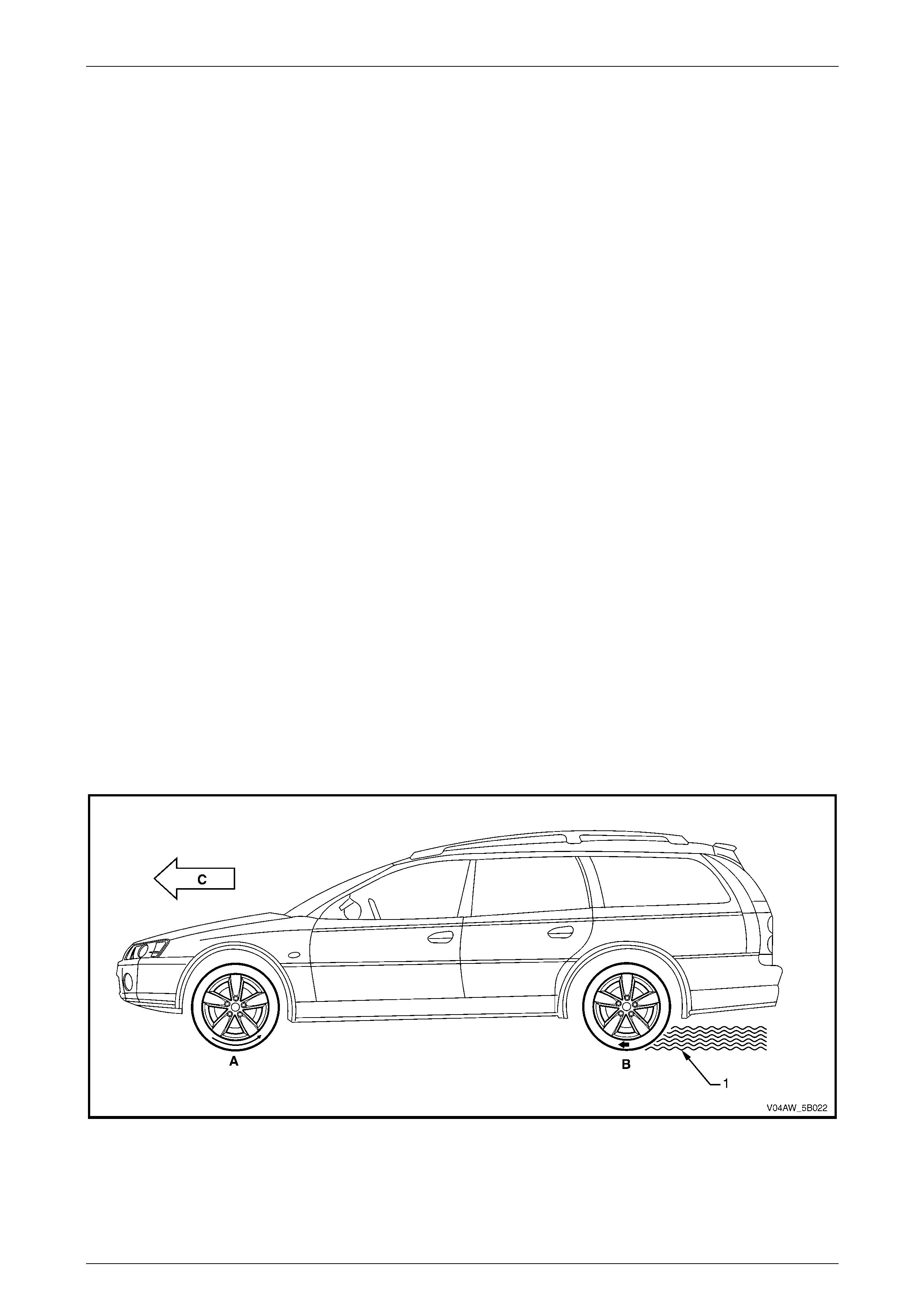
The vehicle braking system is dependent upon tyre traction to the road surface to achieve maximum braking efficiency.
The braking action converts the vehicle's forward motion into heat energy. Maximum braking efficiency is achieved when
a wheel lock-up is prevented and the wheel slip is approximately 12%. Refer to Figure 5B – 1 for the illustration of the
following:
• At 0% slip, the tyre rolls freely (A).
• At 100% slip, the tyre locks-up (B) as the weight of the vehicle (C) pushes the non-rotating tyre along the road
surface (1). The force involved in stopping an 1800 kg vehicle from 100 km/h requires the braking system to
generate approximately 8,100 kilojoule (kJ) of braking energy.
When the tyres are locked-up, the vehicle's forward energy is converted into braking energy (friction) between the
tyre and the road surface. This will result in an unstable and inefficient braking due to the effect of the following
factors:
• Asphalt, cement, gravel or dirt road surfaces provide different degree of tyre traction.
• Oil puddles, ice spots or other contaminants that cause a sudden change in the road surface condition.
• Wet, dry, smooth, rough road surface condition affect tyre traction.
Figure 5B – 1
When none of the wheels are locked during braking, the heat energy produced by the braking action is transferred to
the brake pads and the brake disc. As the friction surfaces between the brake pads and the brake disc are designed to
provide a stable and controlled braking action, a vehicle that is stopped without locking the wheels will stop in a shorter
distance while maintaining directional stability and steering capability.
AW D ABS-TCS Page 5B–5
Page 5B–5
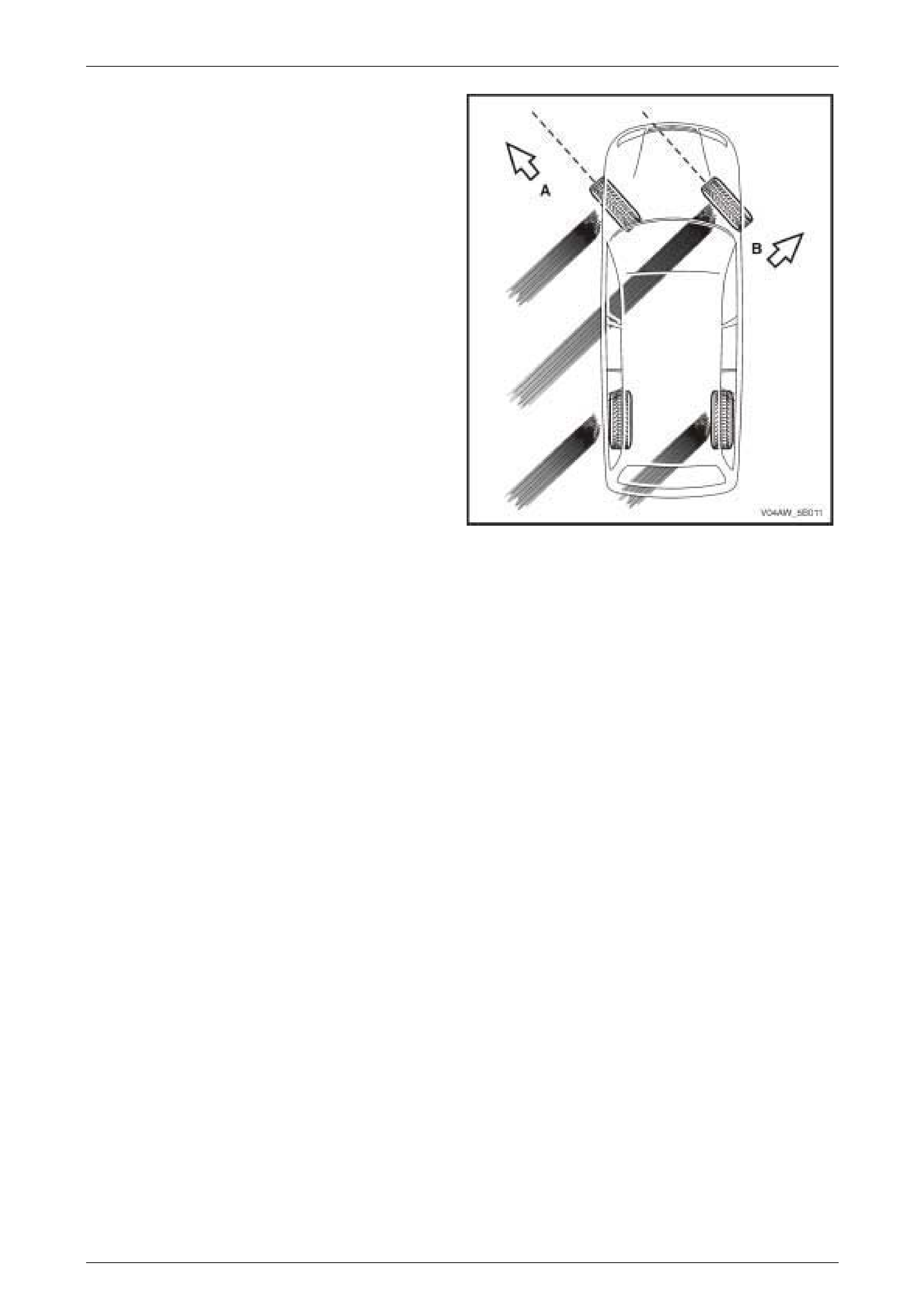
In addition, steering control also depends upon tyre traction.
A locked wheel in a 100% slip condition delivers poor
braking and directional control.
In this example, the front tyre direction (A) has minimal
steering effect while the vehicle slides in direction (B). The
tyres must regain their traction before steering control is
restored to the vehicle.
Figure 5B – 2
Skilled drivers carefully control wheel lock-up by limiting brake pressure, but wheel lock-up on wet roads or in other
reduced traction conditions are difficult to prevent through non-ABS braking.
In theory, the skilled driver limits brake application just short of lock-up. In practice, the driver rapidly pumps the brake
pedal to prevent wheel lock-up. The driver applies, releases, reapplies and releases the brakes until the vehicle stops.
However, the most skilled drivers cannot pump the brakes rapidly or precisely enough for the best braking under all road
surface conditions. In addition, if only one wheel is locking-up, pumping of the brake pedal applies and releases the
brakes at all four wheels at the same time.
The MY 2004 VY AWD Wagon ABS-TCS is designed to provide automatic wheel braking control to each wheel for
optimum vehicle braking, traction and stability under any road surface condition.
AW D ABS-TCS Page 5B–6
Page 5B–6
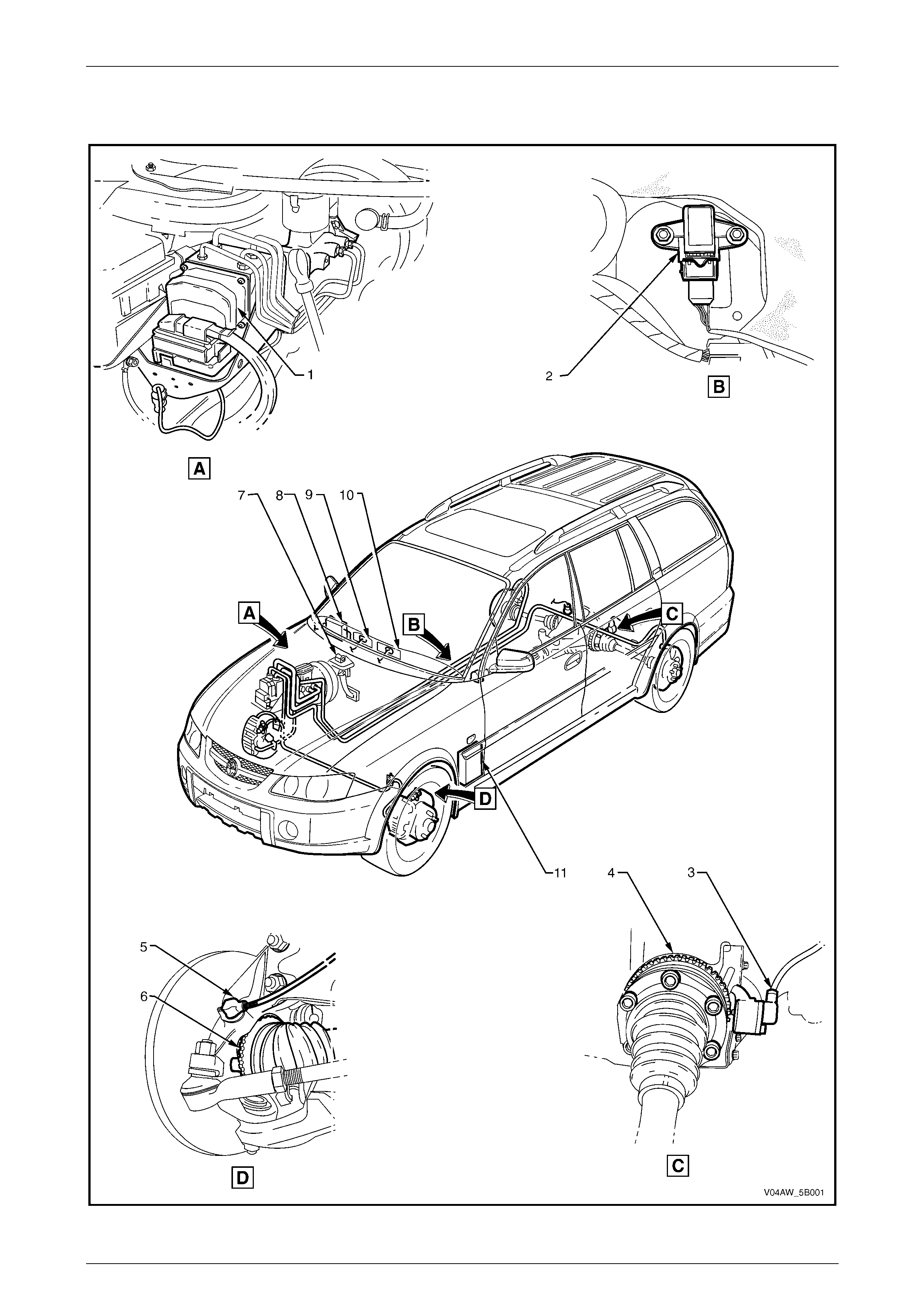
1.1 Component Location
Figure 5B – 3

AW D ABS-TCS Page 5B–7
Page 5B–7
Component Location Legend
1 Elect roni c Control Uni t and
Hydraulic Modulat or A ssembly
2 Longitudinal Accelerometer
3 Rear Wheel Speed Sensor
4 Rear Wheel Speed Sensor Pul se Ring
5 Front Wheel S peed Sensor
6 Front Wheel Speed Sensor P ul se Ring
7 Stop Lamp Switch
8 Body Control Module
9 ABS Icon, ABS Fault and Traction Control Warning Display
10 ABS Warning Lamp
11 Powertrain Interface Module
AW D ABS-TCS Page 5B–8
Page 5B–8
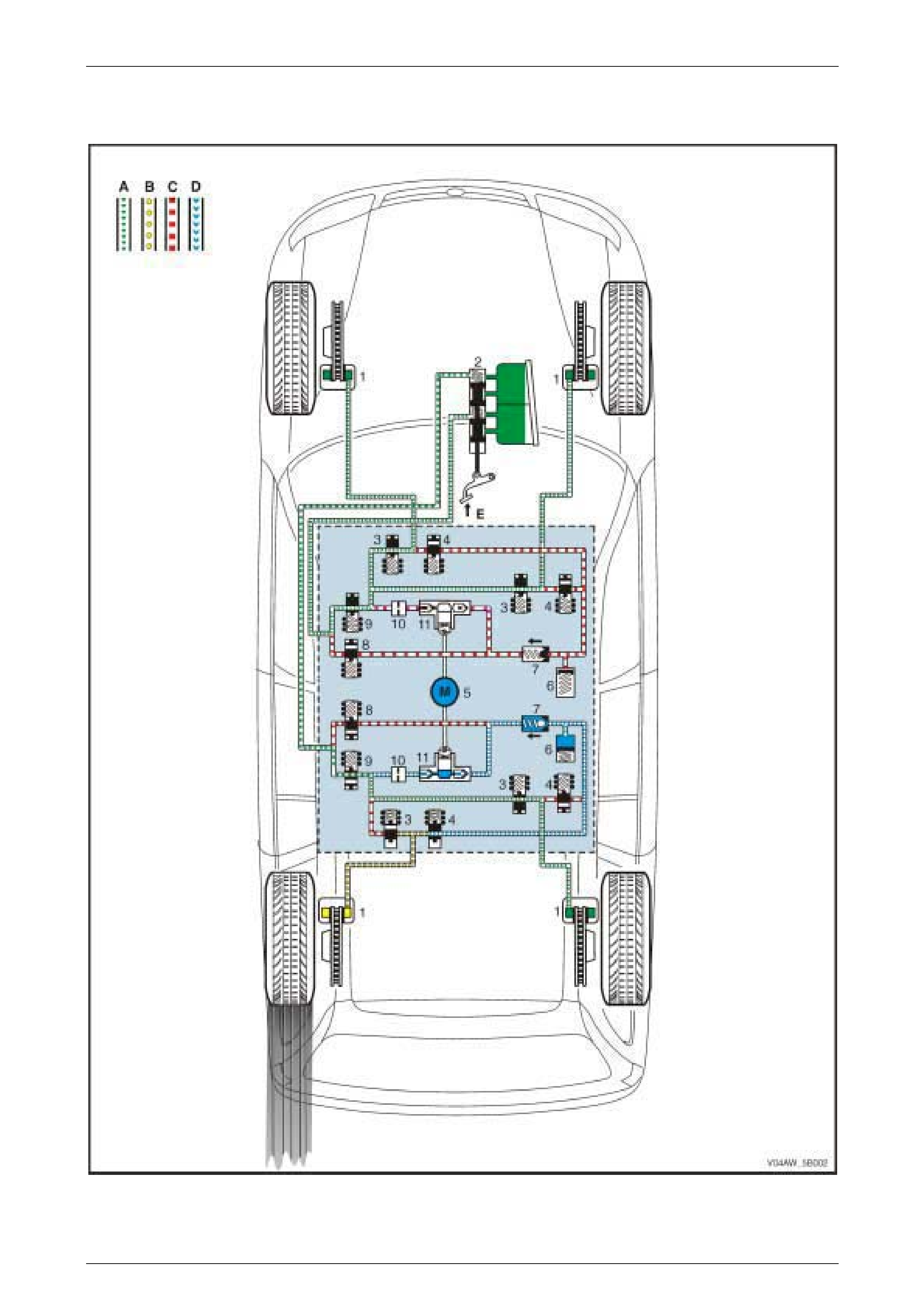
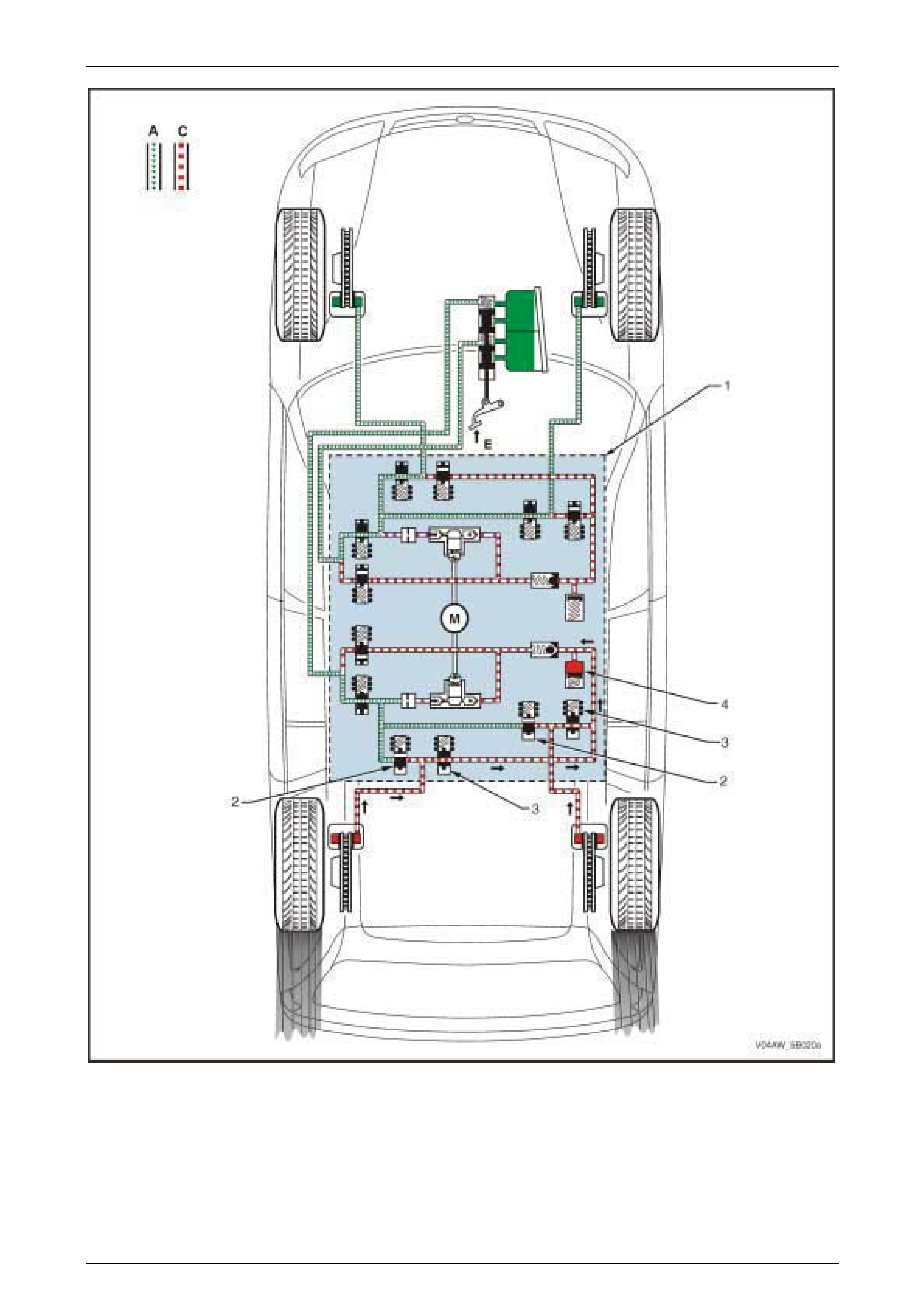
1.2 AWD ABS-TCS Hydraulic Circuit
Figure 5B – 4

AW D ABS-TCS Page 5B–9
Page 5B–9
Hydraulic Circuit Legend
1 Brake Caliper
2 Brake Mast er Cyl i nder
3 Inlet Valve
4 Outlet Valve
5 Pump Motor
6 Accumulator
7 One-way Valve
8 Priming Valve
9 Isolating Valve
10 Hydraulic Damper
11 Hydraulic Pump
A Normal (conventional) B rake Fluid Pressure
B Modulated Brake Flui d P ressure
C St opped B rake Fluid Pressure Flow (Solenoid V al ve Closed)
D hydraulic modul ator Pum p Generated Brake Fl ui d P ressure
Flow
E Brake Pedal A ppl i ed

AW D ABS-TCS Page 5B–10
Page 5B–10
2 System Operation
2.1 Non-ABS Braking
Under normal braking and driving conditions, the ABS-TCS functions like a conventional braking system. Refer to
Section 5A Service and Park Braking System for further information on the conventional braking system.
Non-ABS Braki ng O perat ion
When the brakes are applied (E), the brake booster assists the brake master cylinder (1) in providing brake fluid
pressure (A) to the brake calipers (2) without any intervention from the hydraulic modulator (3). Refer to Figure 5B-5.
However, the Electronic Control Unit (ECU) constantly monitors each wheel for wheel slip. If the ECU detects a wheel
slip, it switches to the appropriate Mode:
• ABS Mode – If any of the wheels begin to lock-up.
• EBD Mode – If the front-to-rear wheel speed is not balanced during braking.
Condition Description
At normal braking, all the valves in the hydraulic modulator are in their normal rest positions allowing for uninterrupted
flow of brake fluid from the master cylinder to the brake calipers. The hydraulic modulator provides conventional non-
ABS braking by allowing the brake fluid to flow between the brake master cylinder and the brake caliper in either
direction.

AW D ABS-TCS Page 5B–11
Page 5B–11
Figure 5B – 5
Legend – Normal Braking Hydraulic Circuit
1 Brake Mast er Cyl i nder
2 Brake Caliper
3 Hydraulic Modulat or A ssembly
A Normal (conventional) B rake Fluid Pressure
C St opped B rake Fluid Pressure Flow (Solenoid V al ve Closed)
E Brake Pedal A ppl i ed
AW D ABS-TCS Page 5B–12
Page 5B–12
2.2 Antilock Braking System (ABS)
The ABS is designed to prevent wheel loc k -up during hard or emergency braking. When the ABS detec ts that a wheel is
beginning to lock-up, the hydraulic modulator reduces the braking force applied by modulating the brake fluid supply
pressure of the locking wheel. The following are conditions that may occur under various ABS-TCS Phases:
ABS-TCS Normal Operating Conditi ons
The following are conditions that may be experienced when the ABS-TCS is activated and are considered normal:
• During ABS-controlled braking, the braking pressure of the affected wheel is automatically adjusted to prevent
wheel lock-up, regardless of brake pedal force.
• During some ABS-TCS operation, the following conditions may be experienced and are considered normal:
• A series of rapid pulsations are felt through the brake pedal – these pulsations occur as solenoid valves
within the hydraulic modulator change position to modulate the brake hydraulic pressure.
• A ticking or popping noise in the hydraulic modulator – this noise occurs as the hydraulic modulator solenoid
valves cycle rapidly to modulate the hydraulic brake pressure.
• Intermittent chirping noises – this noise may be heard as the tyres approach slipping on dry pavement.
• Electric motor and pump noise and rapid brake pedal pulsation – these are caused by the operation of the
hydraulic modulator pump during the ABS/EBD Reducing or Increasing Pressure Phase, ABD Brake
Intervention or the ECU self-test.
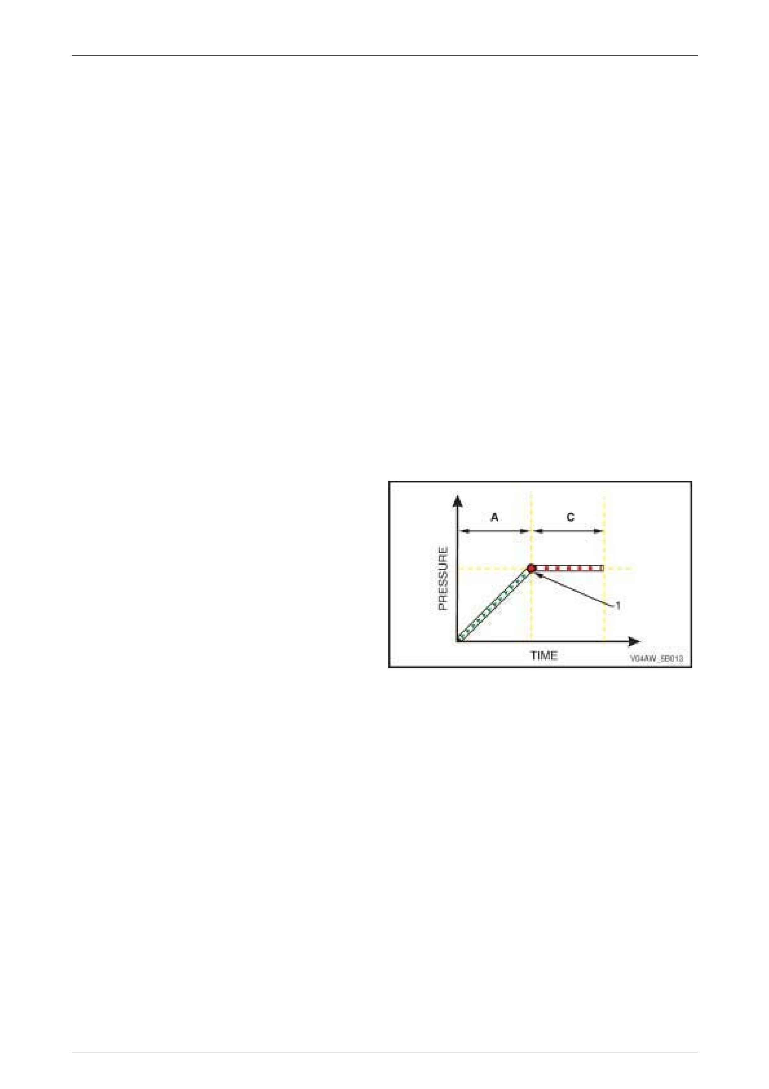
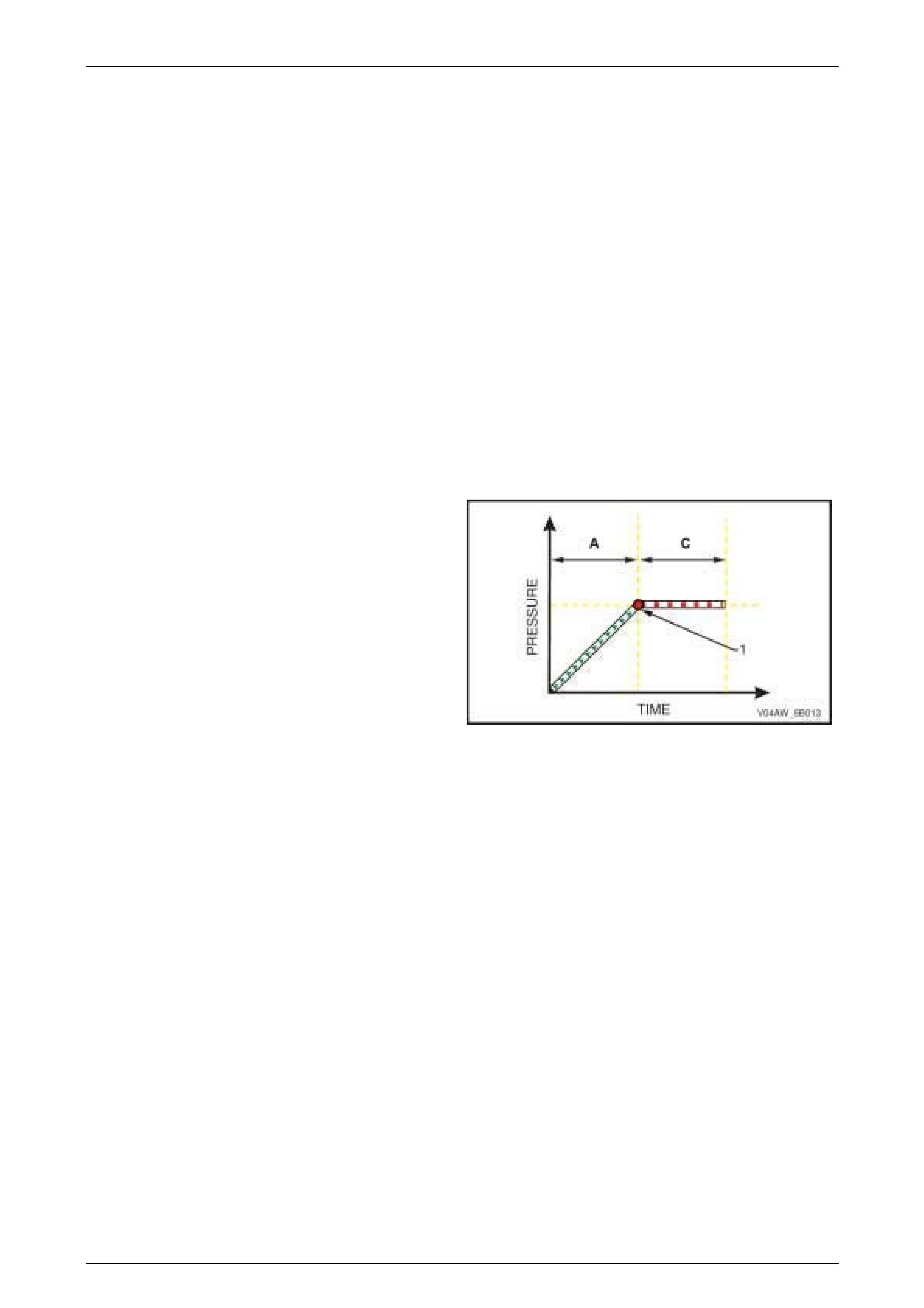
ABS Phase – Mai nt ai ning Pressure
Condition Description
When the brakes are applied (A) and the Electronic Control
Unit (ECU) detects that a wheel reaches a point (1) where it
is beginning to lock-up, the hydraulic modulator controls the
brake fluid pressure of the affected wheel to maintain its
brake fluid pressure (C) and prevent a wheel lock-up.
Figure 5B – 6
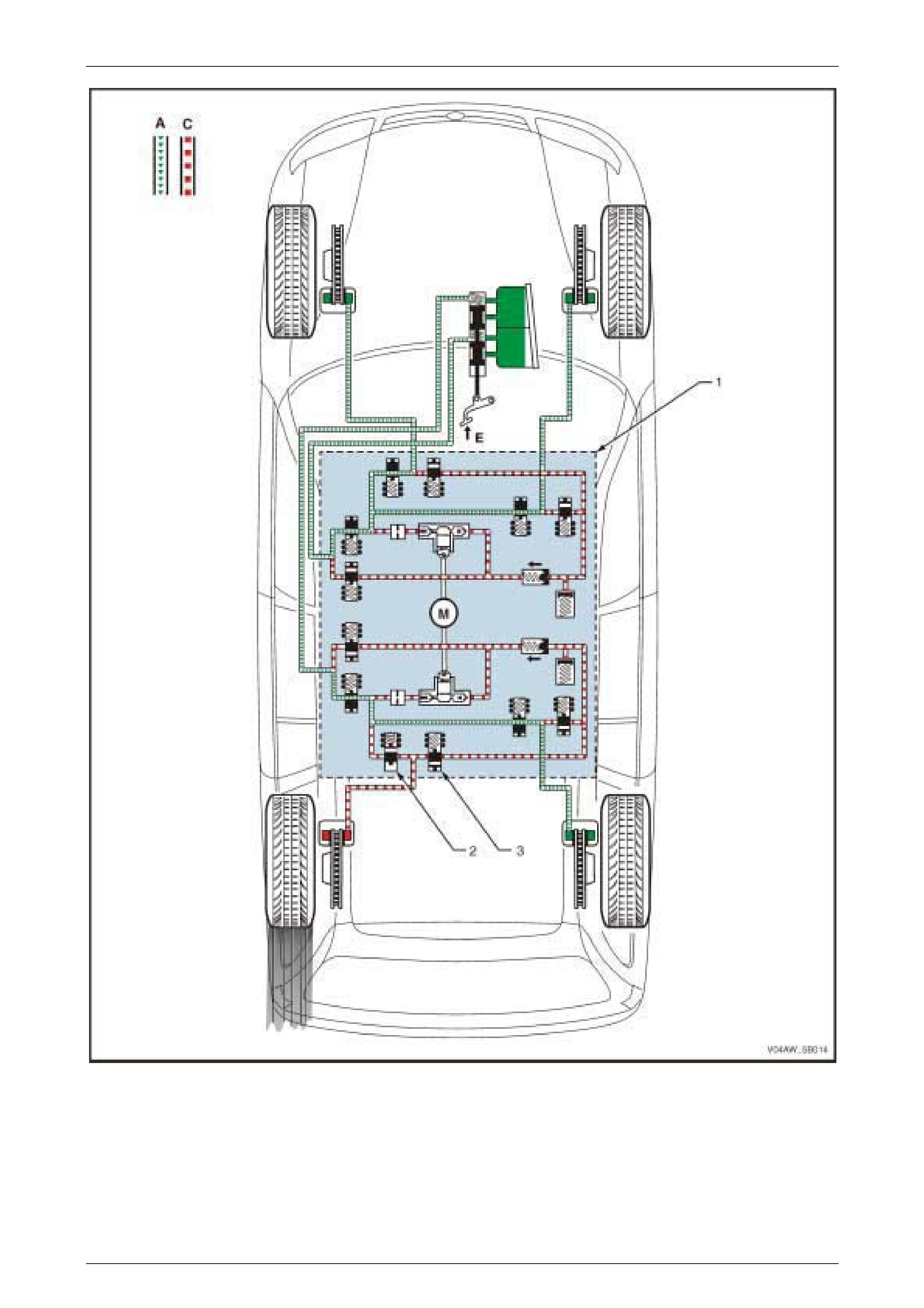
Control Action
NOTE
The following ABS situation assumes that the
rear left wheel is beginning to lock-up. Refer to
Figure 5B – 7 for the illustration of the ABS
Phase – Maintaining Pressure Hydraulic Circuit.
The ECU monitors and compares signals from each wheel speed sensor to determine wheel lock-up or wheel spin. If a
wheel lock-up is detected during braking, the ECU switches to the Maintaining Pressure Phase and sends a control
signal to the hydraulic modulator (1) to close the rear left inlet valve (2).
With both the rear left inlet valve and outlet valve (3) closed, the rear left brake fluid circuit is isolated and the rear left
brake fluid pressure (C) is kept constant regardless of the brake fluid pressure (A) exerted by the brake pedal (E).
AW D ABS-TCS Page 5B–13
Page 5B–13
Figure 5B – 7
Legend – ABS Maintaining Pressure Phase Hydraulic Circuit
1 Hydraulic Modulator
2 Inlet Valve
3 Outlet Valve
A Normal (conventional) B rake Fluid Pressure
C St opped B rake Fluid Pressure Flow (Solenoid V al ve Closed)
E Brake Pedal A ppl i ed
AW D ABS-TCS Page 5B–14
Page 5B–14
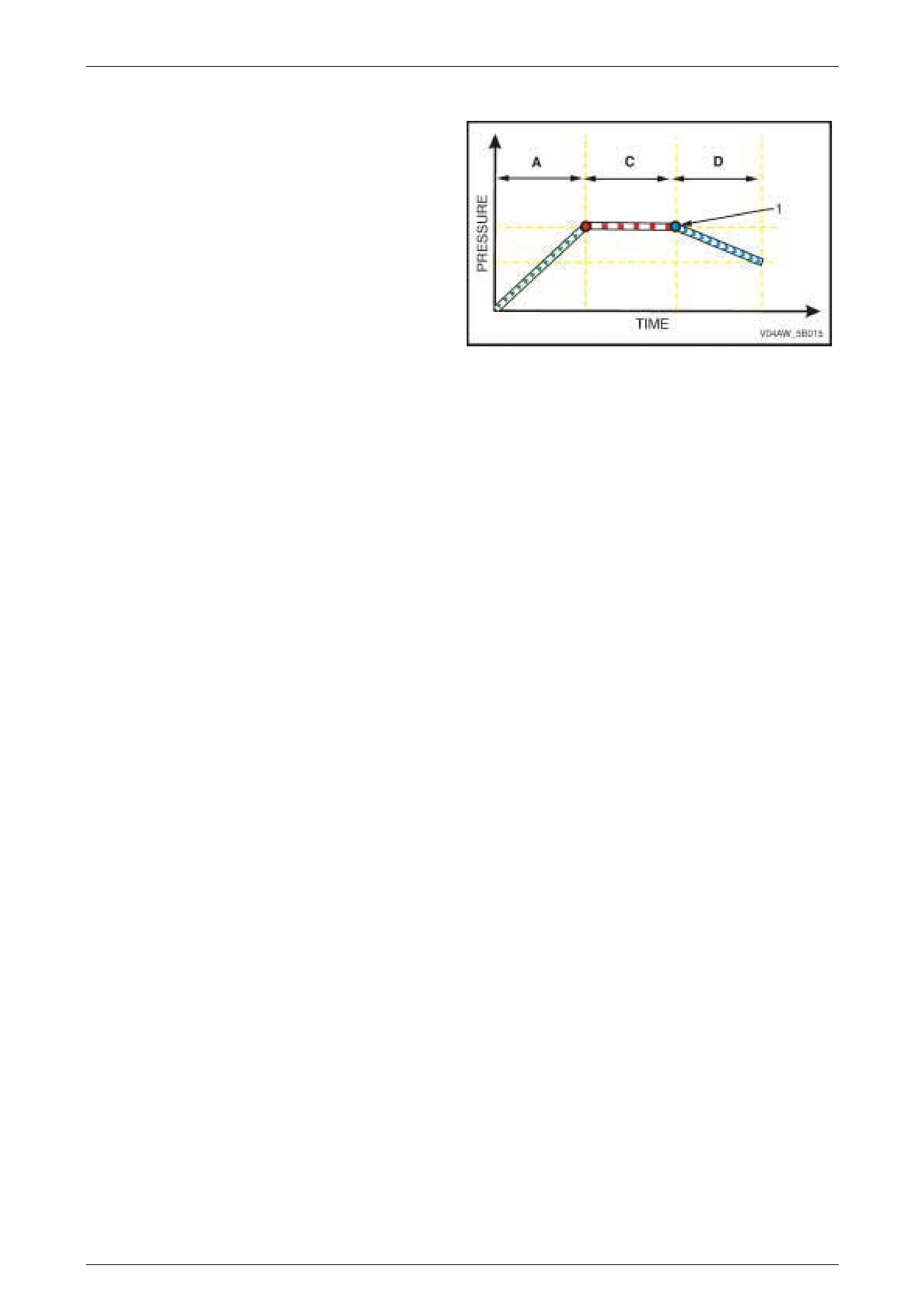
ABS Phase – Reducing Pressure
Condition Description
If maintaining the brake fluid pressure in the Maintaining
Pressure Phase (C) did not prevent the affected wheel from
locking-up (1), the ABS switches from Maintaining Pressure
Phase to Reducing Pressure Phase.
The hydraulic modulator modulates the brake fluid circuit of
the affected wheel to reduce its brake fluid pressure (D) and
prevent wheel lock-up.
Figure 5B – 8
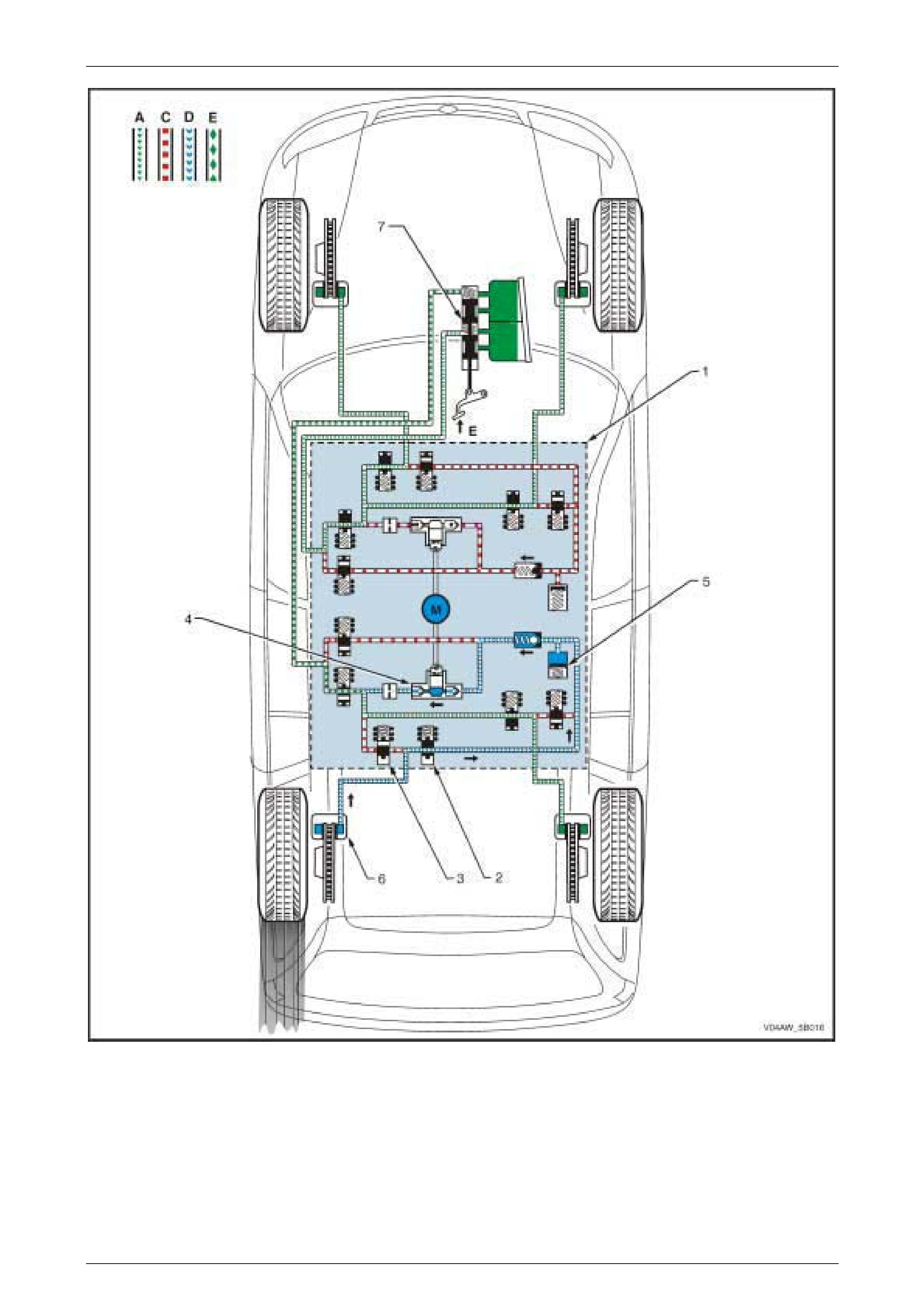
Control Action
NOTE
The following ABS situation assumes that the
rear left wheel is still locking-up while the ABS is
already in Maintaining Pressure Phase. Refer to
Figure 5B – 9 for the illustration of the ABS –
Reducing Pressure Hydraulic Circuit.
The ECU monitors and compares signals from each wheel speed sensor to determine wheel lock-up and wheel spin. If
the rear left wheel lock-up is still detected when the ABS is already in the Maintaining Pressure Phase, the ECU
switches to the ABS Reducing Pressure Phase. The ECU sends a control signal to the hydraulic modulator (1) to:
• Open the rear left outlet valve (2).
• Close rear left inlet valve (3).
• Operate the hydraulic modulator pump (4). The hydraulic modulator pump will remain operational for the duration
of the ABS Phase.
The ABS performs the following actions during the Reducing Pressure Phase:
1 The rear left brake fluid is initially directed towards the accumulator (5) to guarantee instant pressure reduction
when the rear left outlet valve is opened.
2 The accumulator stores the excess rear left brake fluid.
3 The hydraulic modulator pump builds-up the rear left brake fluid return flow pressure that will allow the brake fluid
released from rear left brake caliper (6) to be returned back to the brake master cylinder (7) against brake pedal
pressure (D). Because the brake pedal is still being depressed during this phase, the released pressure from the
brake caliper has to be greater than the brake fluid pressure applied by the master cylinder.
AW D ABS-TCS Page 5B–15
Page 5B–15
Figure 5B – 9
Legend – ABS Reducing Pressure Phase Hydraulic Circuit
1 Hydraulic Modulator
2 Outlet Valve
3 Inlet Valve
4 Hydraulic Pump
5 Accumulator
6 Brake Caliper
7 Brake Mast er Cyl i nder
A Normal (conventional) B rake Fluid Pressure
C St opped B rake Fluid Pressure Flow (Solenoid V al ve Closed)
D hydraulic modul ator Pum p Generated Brake Fl ui d P ressure
Flow
E Conventional Brake Pres sure combined with Releas ed
Brake Fluid P ressure

AW D ABS-TCS Page 5B–16
Page 5B–16
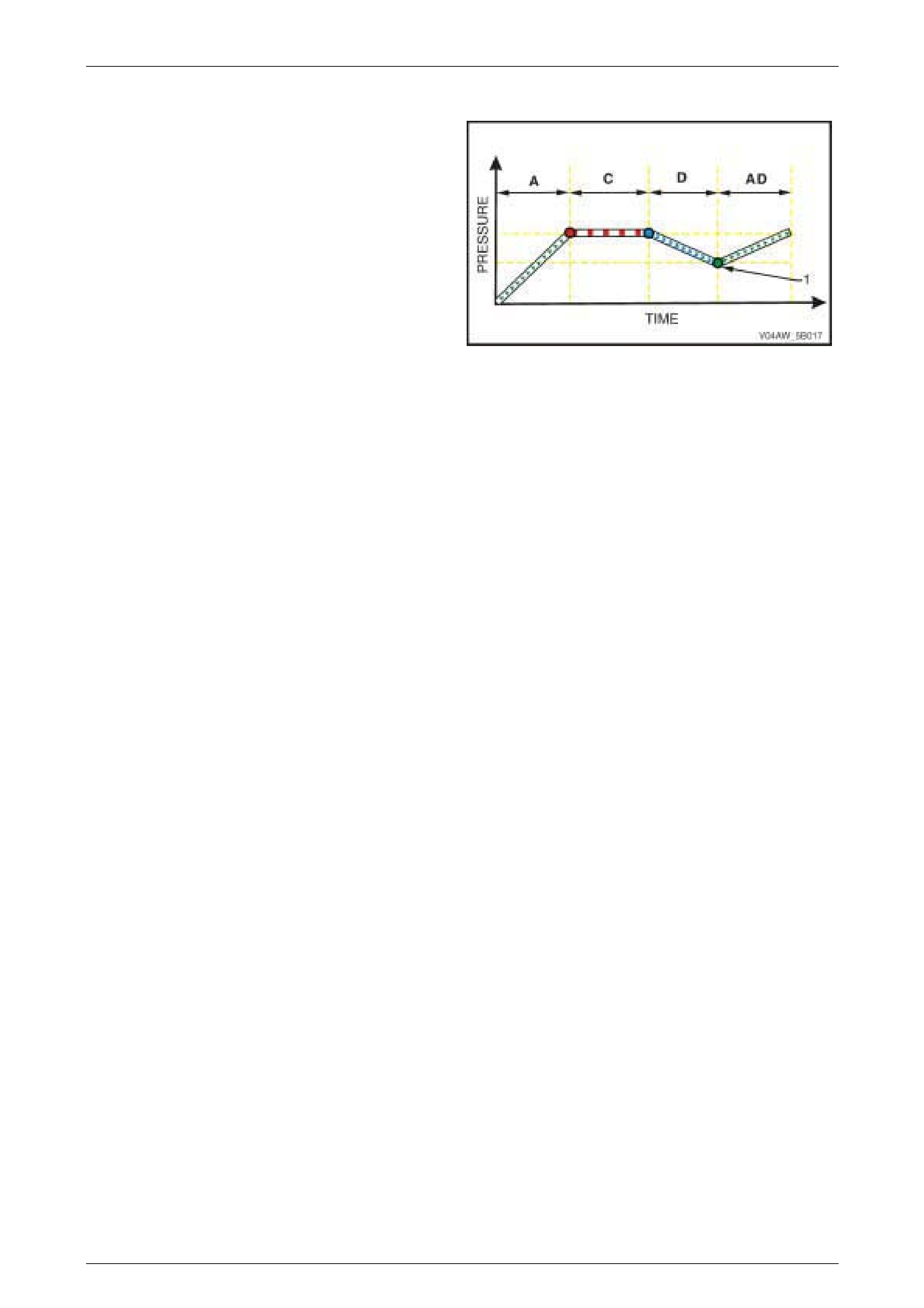
ABS Phase – Increasing Pressure
Condition Description
If reducing the brake fluid pressure in the Reducing
Pressure Phase (D) results in the following:
• The brake fluid pressure reaches a point (1) where
insufficient braking force is applied to the affected
wheel,
• The ECU determines that the affected wheel is now
underbraked.
The ABS switches from Reducing Pressure Phase to
Increasing Pressure Phase (AD). In this phase, the
hydraulic modulator modulates the affected wheel brake
fluid circuit to increase its brake fluid pressure, which
increases braking force and balances wheel speed during
braking.
Figure 5B – 10
Control Action
NOTE
The following ABS situation assumes that the
rear left wheel speed is under braked as a result
of the reduced braking force applied during the
ABS Reducing Pressure Phase. Refer to Figure
5B – 11 for the illustration of the ABS –
Increasing Pressure Hydraulic Circuit.
The ECU monitors and compares signals from each wheel speed sensor to determine wheel lock-up and wheel spin. If
the ECU detects that the rear left wheel speed is higher than the other three wheels as a result of the reduced braking
force applied during the Reducing Pressure Phase, the ECU switches to the Increasing Pressure Phase. The ECU
sends a control signal to the hydraulic modulator (1) to:
• Close (normal position) the rear left outlet valve (2).
• Open (normal position) the rear left inlet valve (3).
• Continue operation of the hydraulic modulator pump (4) for the duration of the ABS Phase.
The master cylinder (5) brake fluid pressure (A) is again directed to the rear left brake caliper (6) as in normal brake
operation. The previously reduced rear left brake fluid pressure is now increased to reduce the rear left wheel speed.
These ABS Phases are repeated until the ECU detects that the wheel speeds are balanced or the brake pedal pressure
removed. There are approximately four to six control cycles per second depending on the road surface condition.

AW D ABS-TCS Page 5B–17
Page 5B–17
Figure 5B – 11
Legend – ABS Increasing Phase Pressure Hydraulic Circuit
1 Hydraulic Modulat or
2 Outlet Valve
3 Inlet Valve
4 Hydraulic P ump Assembly
5 Brake Mast er Cyl i nder
6 Brake Caliper
A Normal (conventional) B rake Fluid Pressure
C St opped B rake Fluid Pressure Flow (Solenoid V al ve Closed)
D hydraulic modul ator Pum p Generated Brake Fl ui d P ressure
Flow
E Brake Pedal A ppl i ed

AW D ABS-TCS Page 5B–18
Page 5B–18
2.3 Automatic Brake Distribution (ABD)
System
The Automatic Brake Distribution (ABD) System is designed to prevent wheel spin during a standing start, acceleration
or cornering. When the ECU is in the ABD Mode, the hydraulic modulator modulates the brake hydraulic circuit of the
spinning wheel and applies appropriate brake fluid pressure, which enables the ABD System to automatically apply
braking force and prevent wheel spin.
A wheel spin causes the following vehicle conditions:
• The rear of the vehicle swerves and the vehicle becomes unstable.
• Increased tyre tread wear.
• High drivetrain stress that may result in premature drivetrain failure when a spinning wheel suddenly finds traction
on a high adhesive surface.
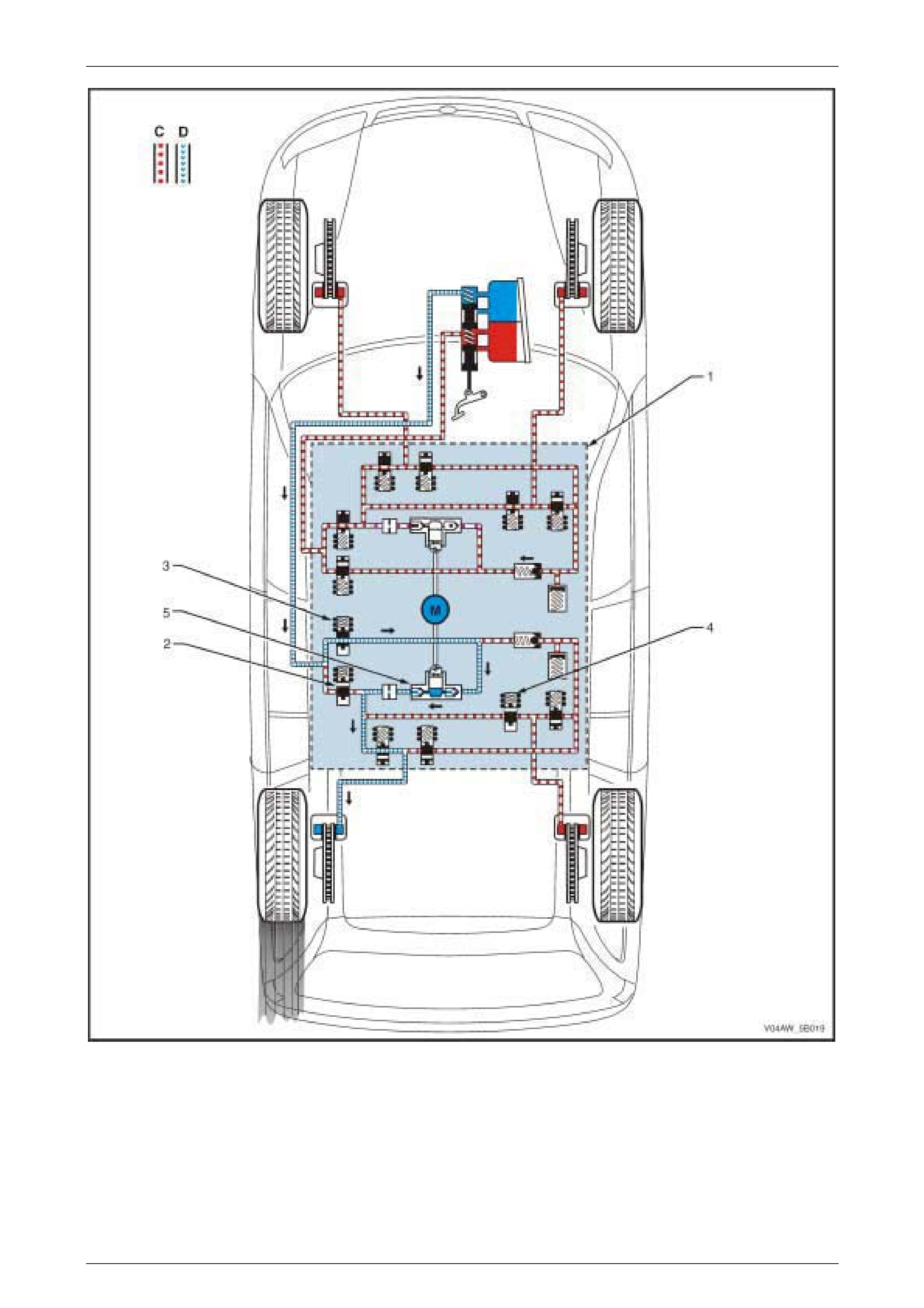
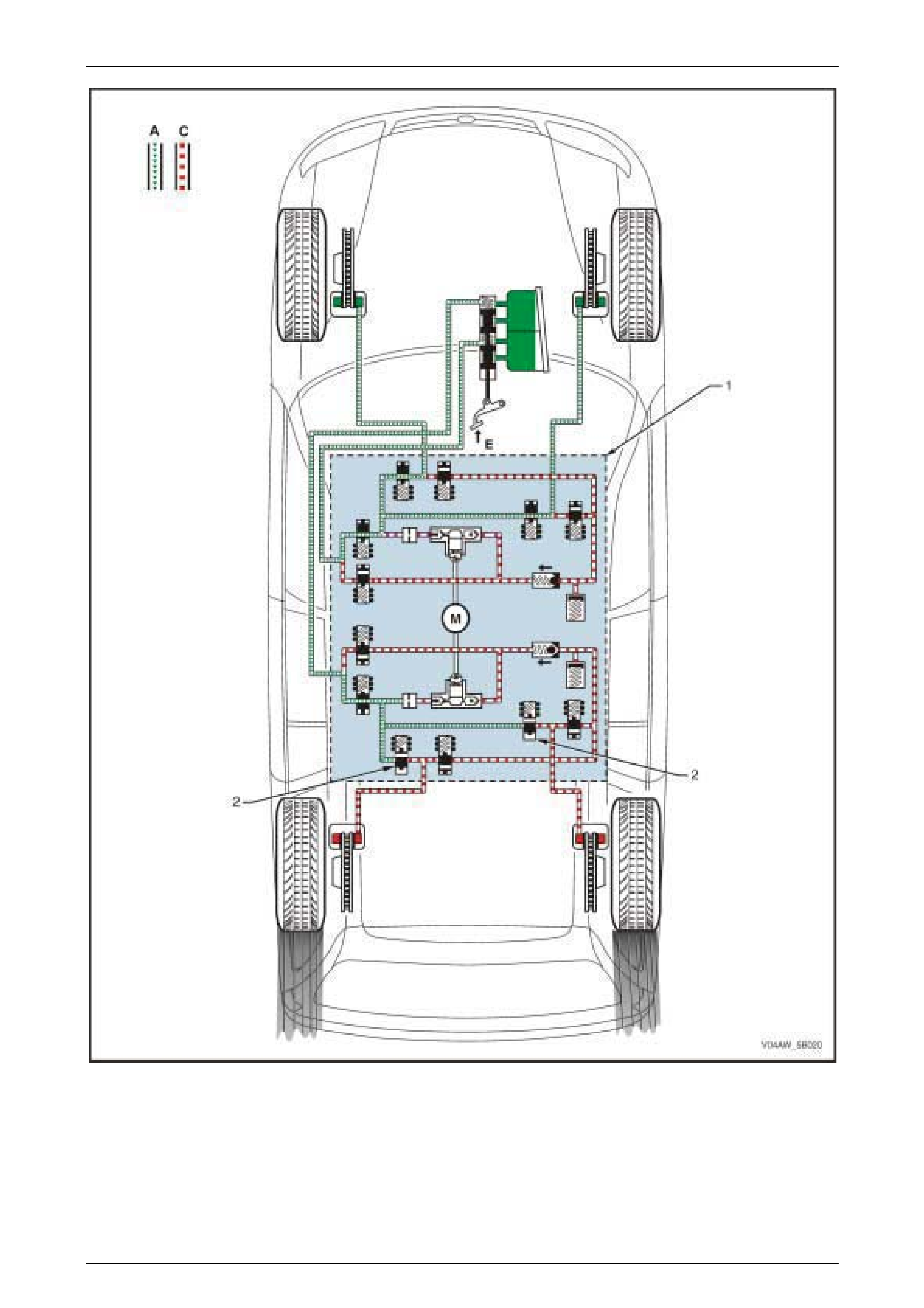
ABD System – Brake Intervention
NOTE
The following ABD System situation assumes
that the rear left wheel is beginning to slip. Refer
to Figure 5B – 12 for the illustration of the
ABD System – Hydraulic System Circuit.
The ECU monitors and compares signals from each wheel speed sensor to determine wheel lock-up and wheel spin. In
addition, the ECU monitors and evaluates signals from the longitudinal accelerometer the rate of vehicle acceleration.
In addition, if the vehicle is travelling on a slippery road condition or on a slope, which causes all four wheels to loose
traction, the ECU uses the longitudinal wheel speed sensor signal voltage to support the calculation of the actual vehicle
speed. Refer to 3.4 Longitudinal Accelerometer for further information on the longitudinal accelerometer.
If the ECU detects that the rear left wheel is beginning to slip due to a slippery road surface or excessive engine torque
and the brakes are not applied, the ECU switches to the ABD Mode. During this Mode, the ECU sends the following
signal to the hydraulic modulator (1) to:
• Close the rear isolating valve (2).
• Open the rear prime valve (3).
• Close the rear right inlet valve (4)
• Operate the hydraulic modulator pump (5).
The hydraulic modulator performs the following operations during the ABD Mode. These operations can be applied
approximately four to six times a second and can function on one or more driven wheels:
• The rear isolation valve is closed to isolate the rear brake fluid circuits from the master cylinder and prevent the
brake fluid returning to the brake master cylinder when the hydraulic pump builds-up the brake fluid pressure.
• The rear right inlet valve is closed to isolate the rear right wheel hydraulic circuit (C) allowing the hydraulic
modulator to supply brake fluid pressure only to the rear left wheel.
• The rear priming valve is open to allow brake fluid to be drawn from the master cylinder into the hydraulic pump
• The hydraulic pump supplies brake fluid pressure (D) to the rear left brake caliper. Applying brake force to the
spinning wheel allows torque to be transferred to the wheel with good traction.
• The rear left wheel inlet and outlet valves cycle open and close to provide sufficient braking force to the rear left
wheel to stop it from spinning. The inlet and outlet valve cycle assists in obtaining maximum road surface traction
in the same manner as the ABS Mode. The difference between ABS and ABD mode is that during ABD Mode, the
brake fluid pressure is increased to reduce wheel spin. In contrast, during the ABS Mode, the brake fluid pressure
is decreased to avoid wheel lock-up.
NOTE
If at any time during ABD Mode the brakes are
manually applied, the brake switch sends a
signal to the ECU to exit the ABD Brake
Intervention Mode and allow for manual braking.
AW D ABS-TCS Page 5B–19
Page 5B–19
Figure 5B – 12
Legend – ABD Mode, Brake Intervention Hydraulic Circuit
1 Hydraulic Modulator
2 Isolating Valve
3 Prime Valve
4 Inlet Valve
5 Hydraulic P ump
C St opped B rake Fluid Pressure Flow (Solenoid V al ve Closed)
D hydraulic modul ator Pum p Generated Brake Fl ui d P ressure
Flow
M Pump Motor
AW D ABS-TCS Page 5B–20
Page 5B–20
2.4 Electronic Brake-force Distribution
(EBD) System
The Electronic Brake-force Distribution (EBD) System is part of the ABS-TCS software programmed into the Electronic
Control Unit (ECU) and is designed to replace the rear brake proportioning valve in preventing rear wheel lock-up during
moderate braking. The EBD System utilises the existing ABS System active controls to regulate the vehicle's rear brake
fluid pressure. This enables the EBD System to provide dynamic front to rear brake proportioning under various vehicle
loads, driving manoeuvres, or road conditions.
In some situations, when the EBD System is activated, a brake pedal height drop of approximately 10 mm will be
experienced when the driver varies the brake pedal pressure while performing brake stops. This is caused by the
hydraulic modulator performing an adjustment on the rear brake fluid pressure and is considered normal. The following
are conditions that may occur under various EBD System Phases:
EBD System Keep Alive Function
The EBD System plays an important role in vehicle stability during braking. For this reason, the EBD System has a Keep
Alive Function integrated in its software. When the ECU detects a fault in the ABS-TCS, depending on the type of
failure, certain parts of the system are kept alive. This allows the EBD System to apply some rear wheel brake
proportioning even under certain ABS-TCS fault conditions.
EBD – Maintai n i ng Pressure
Condition Description
When the brakes are applied (A) and the ECU determines
that the rear wheels reach a point (1) where their rotational
speed is decelerating faster than the front wheels, the
hydraulic modulator individually modulates the rear wheel
brake fluid pressure (C) to maintain the rear braking force
and prevent a wheel lock-up.
NOTE
The EBD System operation takes effect before
the increased slip rate required for an ABS
brake intervention.
Figure 5B – 13
Control Action
NOTE
The following EBD situation assumes that the
rear wheels are beginning to slip. Refer to Figure
5B – 14 for the illustration of the EBD Hydraulic
Circuit.
The ECU monitors and evaluates signals from each wheel speed sensor to determine wheel lock-up or wheel spin.
When the ECU determines that the rear wheels are decelerating faster than the front wheels but the rate of deceleration
doesn't reach a point where it requires ABS intervention, the ECU switches to EBD Maintaining Pressure Phase.
As a first step during the EBD Maintaining Pressure Phase, the ECU sends a control signal to the hydraulic modulator
(1) to close the rear inlet valves (2) and isolate the rear brake fluid circuit from the brake master cylinder. This maintains
the rear brake fluid pressure (C) regardless of the brake fluid pressure (A) exerted by the brake pedal (E).
AW D ABS-TCS Page 5B–21
Page 5B–21
Figure 5B – 14
Legend – EBD Maintaining Pressure Phase Hydraulic Circuit
1 Hydraulic Modulator
2 Rear Inlet V al ve
A Normal (conventional) B rake Fluid Pressure
C St opped B rake Fluid Pressure Flow (Solenoid V al ve Closed)
E Brake Pedal A ppl i ed
AW D ABS-TCS Page 5B–22
Page 5B–22
EBD Phase – Reducing Pressure
Condition Description
If maintaining the brake fluid pressure in the EBD System
Maintaining Pressure Phase (C) did not prevent the rear
wheels from decelerating faster than the front wheels, the
EBD System switches from Maintaining Pressure Phase to
Reducing Pressure Phase (D).
The hydraulic modulator modulates the rear wheel brake
fluid circuits to reduce its brake fluid pressure and prevent
wheel lock-up.
NOTE
The EBD System operation takes effect before the
increased slip rate required for an ABS brake intervention.
Figure 5B – 15
Control Action
NOTE
The following EBD System situation assumes
that the rear wheels are still decelerating faster
than the front wheels while the EBD System is
already in Maintaining Pressure Phase. Refer to
Figure 5B – 16 for the illustration of the EBD –
Reducing Pressure Hydraulic Circuit.
If the ECU detects that the rear wheels are still decelerating faster than the front wheels while the EBD System is
already in Maintaining Pressure Phase, the ECU switches to the Reducing Pressure Phase. The ECU sends a control
signal to the hydraulic modulator (1) to:
• Close the rear inlet valves (2).
• Open the rear outlet valves (3).
The EBD performs the following actions during the Reducing Pressure Phase:
1 The rear brake fluid is directed towards the accumulator (4) to allow brake fluid pressure reduction.
2 The accumulator stores the excess rear brake fluid. It is capable of storing all the excess brake fluid during an
EBD System operation. However, if the accumulator has been filled to its limit and the ECU still determines that
the rear wheels are decelerating faster than the front wheels, the ECU activates the hydraulic modulator pump and
returns the excess brake fluid to the brake master cylinder.
AW D ABS-TCS Page 5B–23
Page 5B–23
Figure 5B – 16
Legend – EBD Reducing Pressure Phase Hydraulic Circuit
1 Hydraulic Modulator
2 Rear Inlet V al ve
3 Rear Outlet V al ve
4 Accumulator
A Normal (conventional) B rake Fluid Pressure
C St opped B rake Fluid Pressure Flow (Solenoid V al ve Closed)
E Brake Pedal A ppl i ed
AW D ABS-TCS Page 5B–24
Page 5B–24
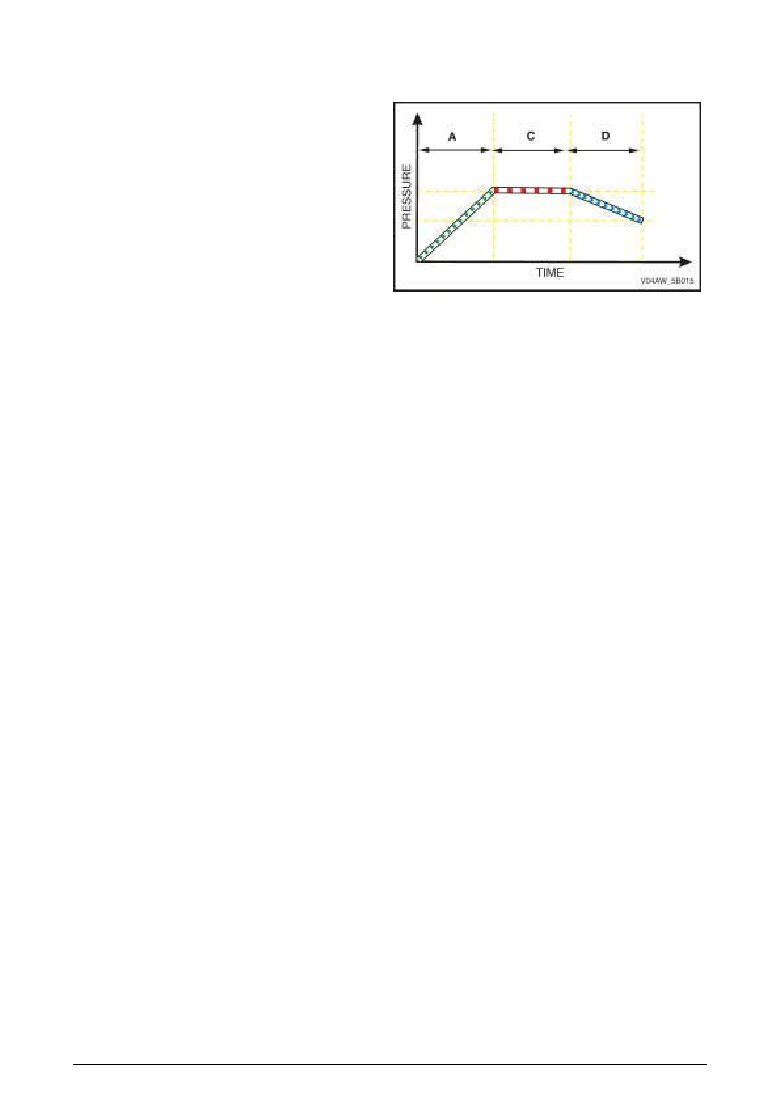
EBD Phase – Increasing Pressure
Condition Description
If reducing the rear brake fluid pressure in the EBD
Reducing Pressure Phase (D) causes the brake fluid
pressure to drop to a point (1) where the front and rear
wheels are now rotating at the same speed or almost at the
same speed, the EBD System switches from Reducing
Pressure Phase to Increasing Pressure Phase (AD).
In this phase, the ECU sends a signal to the hydraulic
modulator to allow normal brake master cylinder pressure to
be applied to the rear wheels as in normal brake operation.
Figure 5B – 17
Control Action
NOTE
The following EBD System operation assumes
that the front and rear wheels are now rotating at
the same speed or almost at the same speed, as
a result of the reduced braking force applied
during the EBD Reducing Pressure Phase.
The ECU monitors and compares signals from each wheel speed sensor to determine wheel lock-up and wheel spin. If
the ECU detects that the front and rear wheels are now rotating at the same speed or almost at the same speed as a
result of the reduced braking force applied during the EBD Reducing Pressure Phase, the EBD System switches from
Reducing Pressure Phase to Increasing Pressure Phase.
The ECU sends a control signal to the hydraulic modulator to return the rear outlet valve and the rear inlet valve to their
normal rest position.
The master cylinder brake fluid pressure is directed to the rear brake calipers as in normal brake operation. The
previously reduced rear brake fluid pressure is now increased to normal brake master cylinder pressure and the front
and rear wheels brake fluid pressures are again equal.
These EBD Phases are repeated until the ECU detects that the wheel speeds are balanced or the brake pedal pressure
removed. There are approximately four to six control cycles per second depending on the road surface condition.
AW D ABS-TCS Page 5B–25
Page 5B–25
3 Component Description and
Operation
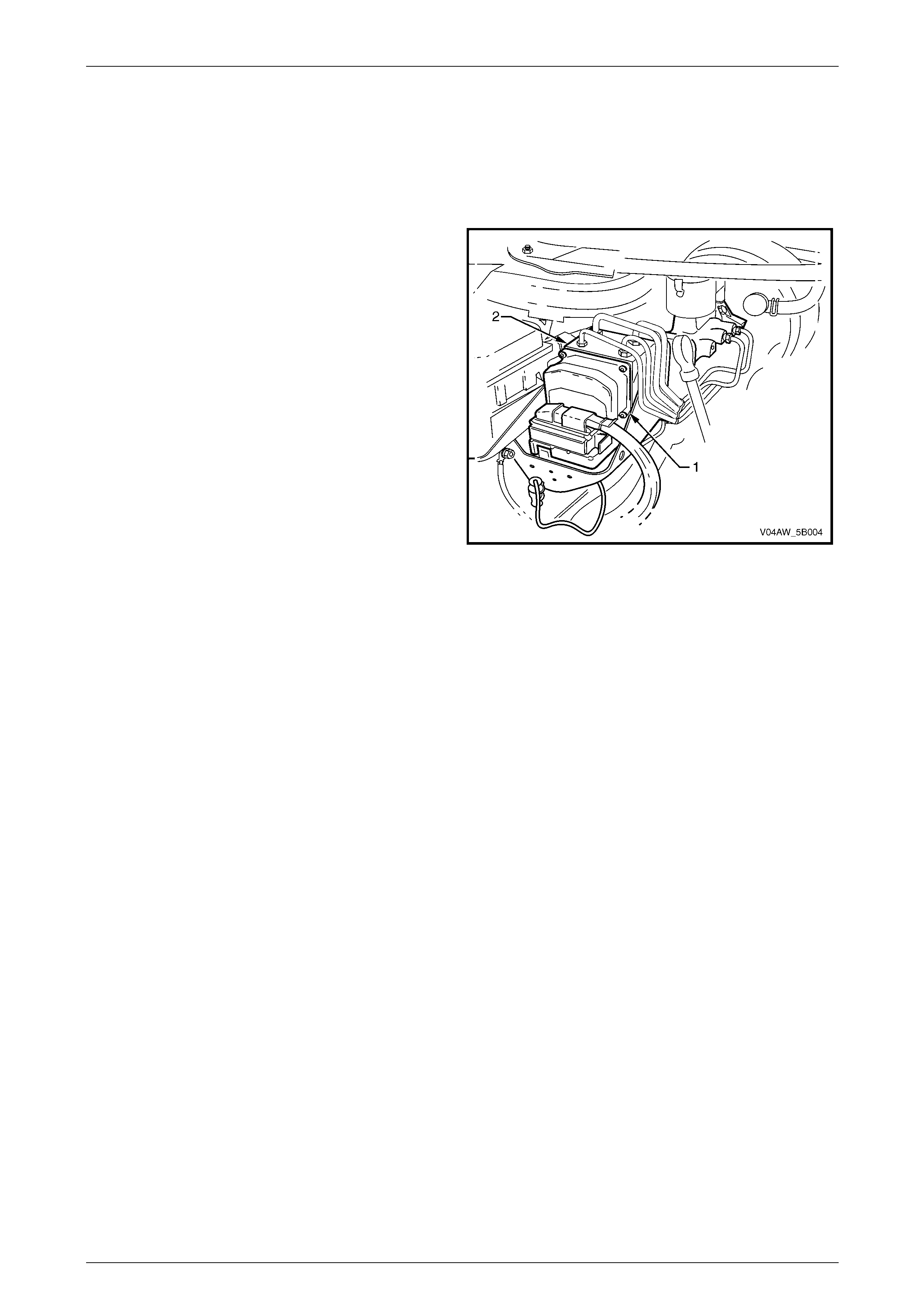
3.1 Electronic Control Unit (ECU)
The Electronic Control Unit (ECU) (1) is the control centre of
the ABS-TCS Braking System. It is integrated with the
hydraulic modulator (2) to form one assembly.
The ECU constantly monitors and evaluates input signals
from various sensors and switches. If it detects a wheel spin
or a wheel slip condition, the ECU switches to the following
Mode:
• ABS Mode – Refer to
2.2 Antilock Braking System (ABS).
• ABD Mode – Refer to
2.3 Automatic Brake Distribution (EBD) System.
• EBD Mode – Refer to
2.4 Electronic Brake-force Distribution (EBD) System.
Figure 5B – 18
ECU Self-test Initialisation Sequence
NOTE
If the ECU detects a fault in the ABS-TCS
Braking System, it takes the following action:
• The ECU will disable the ABS-TCS Braking
System.
• The ABS-TCS remains disabled until the next
ignition cycle.
• Illuminate the warning lamps.
• Sets a DTC.
NOTE
Conventional braking system is available while
the ABS-TCS is disabled.
The ECU performs one Self-test Initialisation Sequence for each ignition cycle. This Initialisation Sequence commences
when the vehicle reaches approximately 6 km/h.
During the Initialisation Sequence, the ECU sends a control signal to the hydraulic modulator to cycle each of the
solenoid valve as well as the pump motor for approximately 1.5 seconds to check for correct component operation. If the
pump or any solenoid valves fail to operate, the ECU will disable the ABS-TCS Braking System, illuminate the warning
lamp and sets a DTC.
NOTE
The Initialisation Sequence may be heard and
felt while it is taking place, which is considered
part of the normal system operation. Refer to,
2.2 Antilock Braking System (ABS).
In addition, as soon as the ECU receives a signal from any of the wheel speed sensors, it checks all the wheel speed
sensor outputs. If any of the wheel speed sensor signals are not detected, or are incorrect, the ECU will disable the
ABS-TCS Braking System, illuminate the warning lamps and sets a DTC.

AW D ABS-TCS Page 5B–26
Page 5B–26
Once the vehicle speed exceeds 6 km/h, the ECU continuously monitors the ABS-TCS by comparing the logical
sequence of input and output signals with the normal operating parameter stored in the ECU . If any of the input or
output signals are outside the normal operating parameters, the ECU will disable the ABS-TCS Braking System,
illuminate the warning lamps and set a DTC.
ECU Inputs
The ECU constantly monitors and evaluates the input signals from the following components:
• Wheel speed sensors.
• Stop lamp switch.
• Longitudinal accelerometer sensor.
• Ignition ON input.
• Battery voltage.
• Engine speed signal.
• Serial data (input and output).
ECU Output s
Based on the inputs received, the ECU sends output signals to the following ABS-TCS components:
• ABS warning lamp.
• Multifunction Display (MFD) ABS icon, ABS fault, low traction and trac off display.
• Class 2 serial data.
• Diagnostic link.
• hydraulic modulator solenoid valves.
• hydraulic modulator pump motor.
AW D ABS-TCS Page 5B–27
Page 5B–27
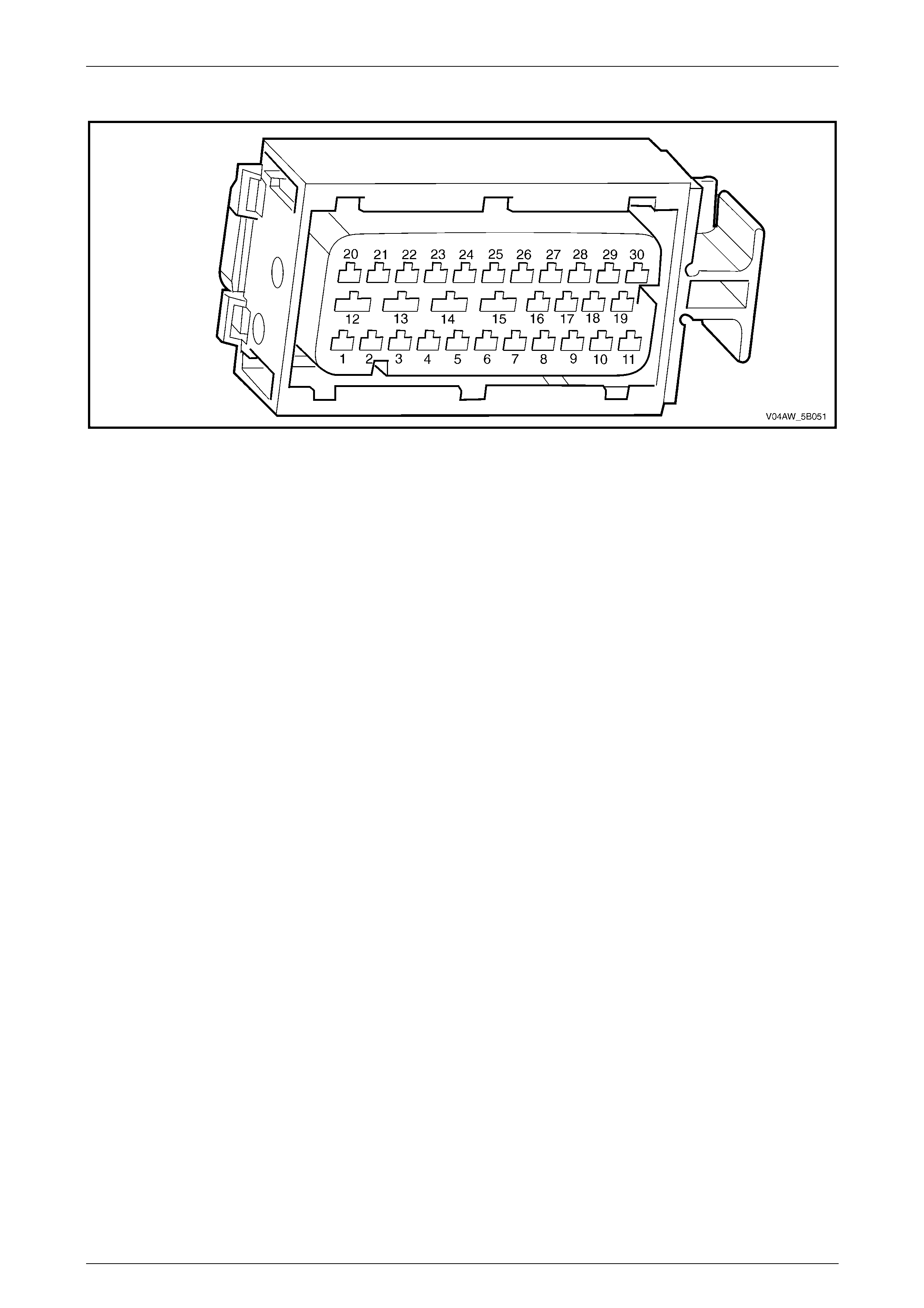
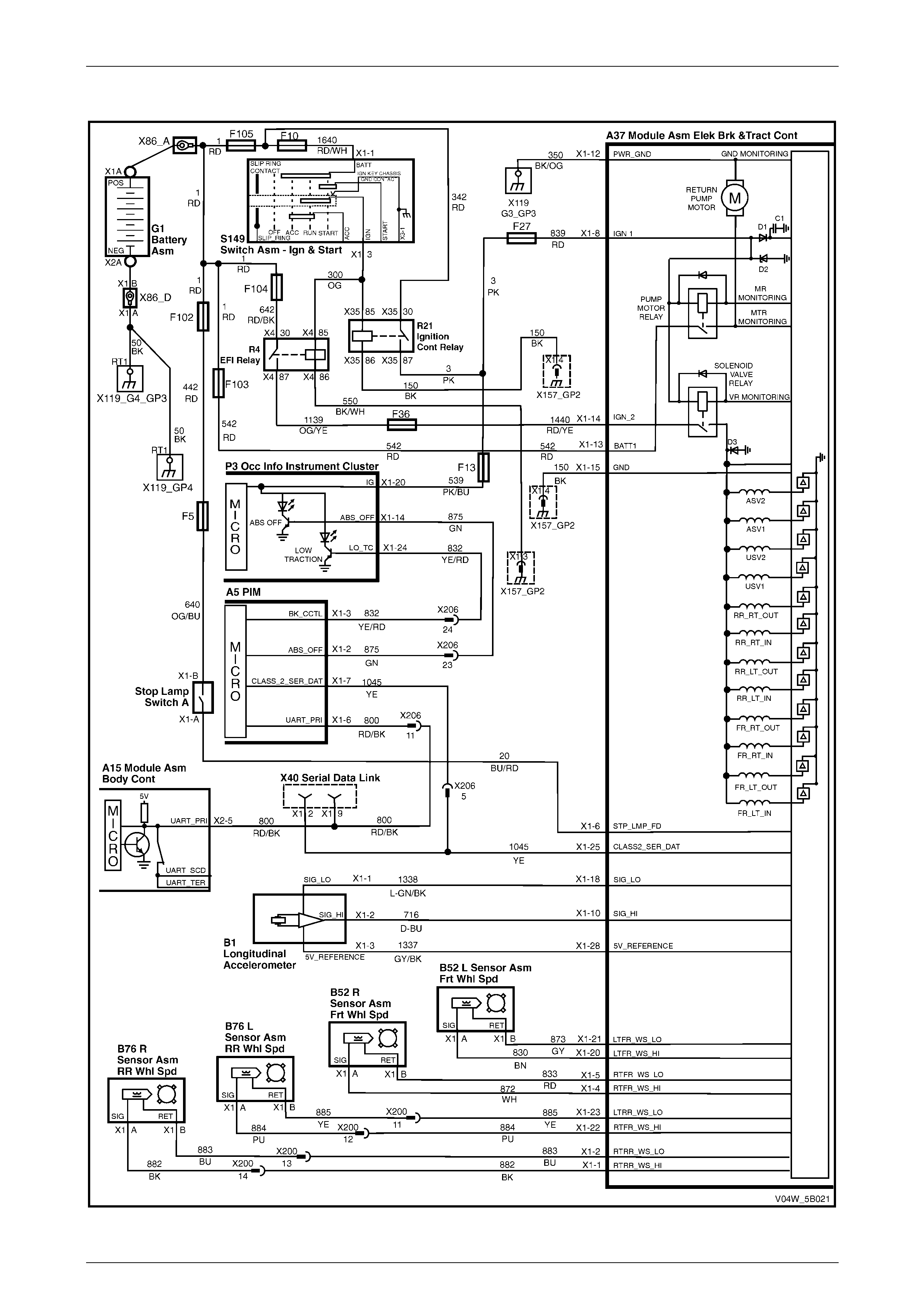
ECU Wiring Connector Terminal Assignment
Figure 5B – 19
ECU Wiring Connector Terminal Assignment Legend
1 Rear Right Wheel Speed Sensor – Signal Circ ui t 882 16 Not Used
2 Rear Right Wheel Speed Sensor – Low Ref. Ci rcuit 883 17 Not Used
3 Not Used 18 Longitudinal A ccelerometer – Low Referenc e Ci rcuit 1337
4 Front Right Wheel Speed Sensor – Signal Ci rcuit 872 19 Not Used
5 Front Right Wheel Speed Sensor – Low Ref. Circui t 833 20 Front Left Wheel Speed Sensor – Signal Ci rcuit 830
6 Stop Light Switch – 12 volt s Signal Ci rcuit 20 21 Front Left Wheel Speed Sensor – Low Ref. Circ ui t 873
7 Not Used 22 Rear Left Wheel Speed Sens or – S i gnal Ci rcuit 884
8 12 volts Ignition Supply Volt age – Igniti on Ci rcuit 839 23 Rear Left Wheel Speed Sens or – Low Ref. Ci rcuit 885
9 Not Used 24 Not Used
10 Longitudinal A ccelerometer – Signal Circuit 716 25 Class 2 Serial Data Bus Circ ui t 1045
11 Not Used 26 Not Used
12 Relays, Valves and Pu mp Motor – Main Ground Circuit 350 27 Not Used
13 12 volts Uni nterrupted Suppl y V ol tage – Fuse 103 Circuit
542 28 Longitudinal A ccelerometer – 5 vol ts Ref erence Circuit 1337
14 12 volts Uni nterrupted Suppl y V ol tage – Fuse 36 Circuit
1440 29 Not Used
15 Ground – ECU Ground Circui t 150 30 Not Used
AW D ABS-TCS Page 5B–28
Page 5B–28
ECU Wiring Diagram
Figure 5B – 20
AW D ABS-TCS Page 5B–29
Page 5B–29
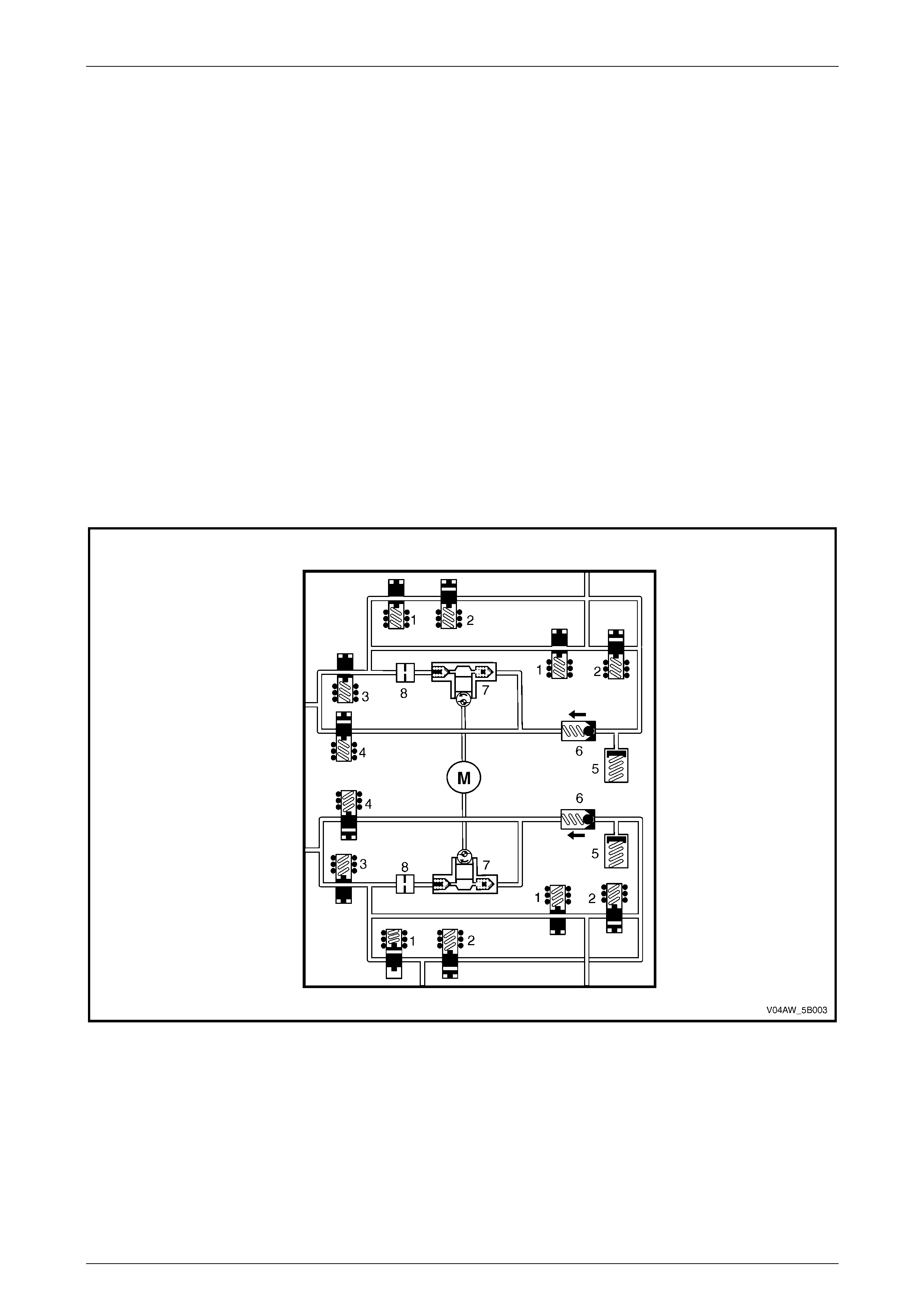
3.2 Hydraulic Modulator
The Hydraulic Modulator modulates the brake fluid pressure based on the control signal sent by the Electronic Control
Unit (ECU).
To allow individual control of each wheel brake fluid circuit, a four-channel circuit configuration with a front/rear split has
been used. Each of the brake fluid circuits is hydraulically isolated, which enables continued braking ability if a leak
develops in any of the brake fluid circuits. The internal components of the hydraulic modulator consist of the following:
(refer to Figure 5B – 21)
• Four inlet solenoid valves (1).
• Four outlet solenoid valves (2).
• Two isolating solenoid valves (3).
• Two priming solenoid valves (4).
• Two accumulators (5).
• Two one-way valves (6).
• Two hydraulic pumps (7).
• Two dampers (8).
• Pump motor (M)
Figure 5B – 21
AW D ABS-TCS Page 5B–30
Page 5B–30
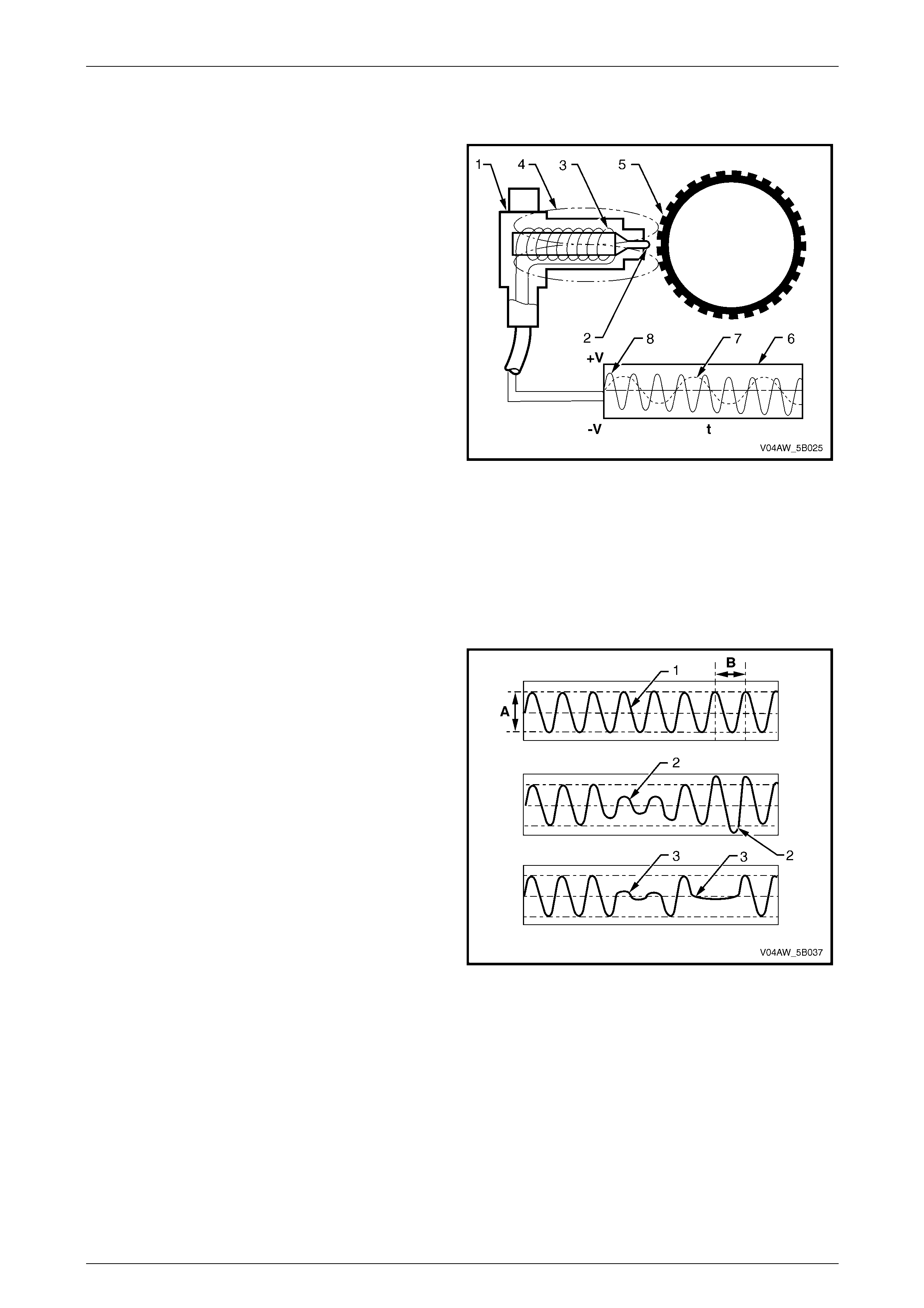
3.3 Wheel Speed Sensors
The front and rear wheel speed sensors (1) consist of a
pole pin (2) surrounded with a coil winding (3). The pole pin
tip is positioned pointing to the pulse ring (5) and is
attached to a permanent magnet that projects a magnetic
field (4) towards the pulse ring.
As the wheel turns, the teeth of the pulse ring induces
changes in the magnetic field of the pole pin and the coil
winding. The magnetic flux thereby changes and an
alternating voltage (6) is induced in the coil of the wheel
speed sensor.
The number of turns of the coil, the magnetisation level of
the pole pin and the number of pulse ring teeth are constant
and the only variable is the wheel RPM. Therefore, the
frequency and amplitude of the output signal depend on the
speed of wheel rotation.
The dotted line (7) represents the voltage generated by the
wheel speed sensor versus time (t) at low wheel speed.
The continuous line (8) represents the voltage generated by
the wheel speed sensor versus time (t) at high wheel
speed.
Figure 5B – 22
Testing Wheel Speed Sensor Using an Oscilloscope
Using an oscilloscope to display the output signal voltage of a suspected wheel speed sensor will enable the service
technician to graphically view a pulse ring related wheel speed sensor fault condition that may be difficult to detect
otherwise.
A normal wheel speed sensor signal produces a sine wave
with the height of the amplitude (A) and the width of the
frequency (B) proportional to the wheel speed.
If the pulse ring is out of round or if it is incorrectly aligned
with the wheel speed sensor, the air gap between the wheel
speed sensor and the pulse ring will vary as the wheel
rotates. This fault condition will produce a wheel speed
sensor signal with varying amplitude (2).
If the pulse ring teeth are missing or damaged, the
oscilloscope sine wave pattern will display flat spots (3) that
represent the missing or damaged pulse ring teeth.
Figure 5B – 23
AW D ABS-TCS Page 5B–31
Page 5B–31
Wheel Speed Sensor Wiring Connect or
Legend
1 Wheel Sensor Wiri ng Connector
A Wheel Sensor Signal Ci rcuit
B Wheel Sensor Low Reference Circ ui t
Figure 5B – 24
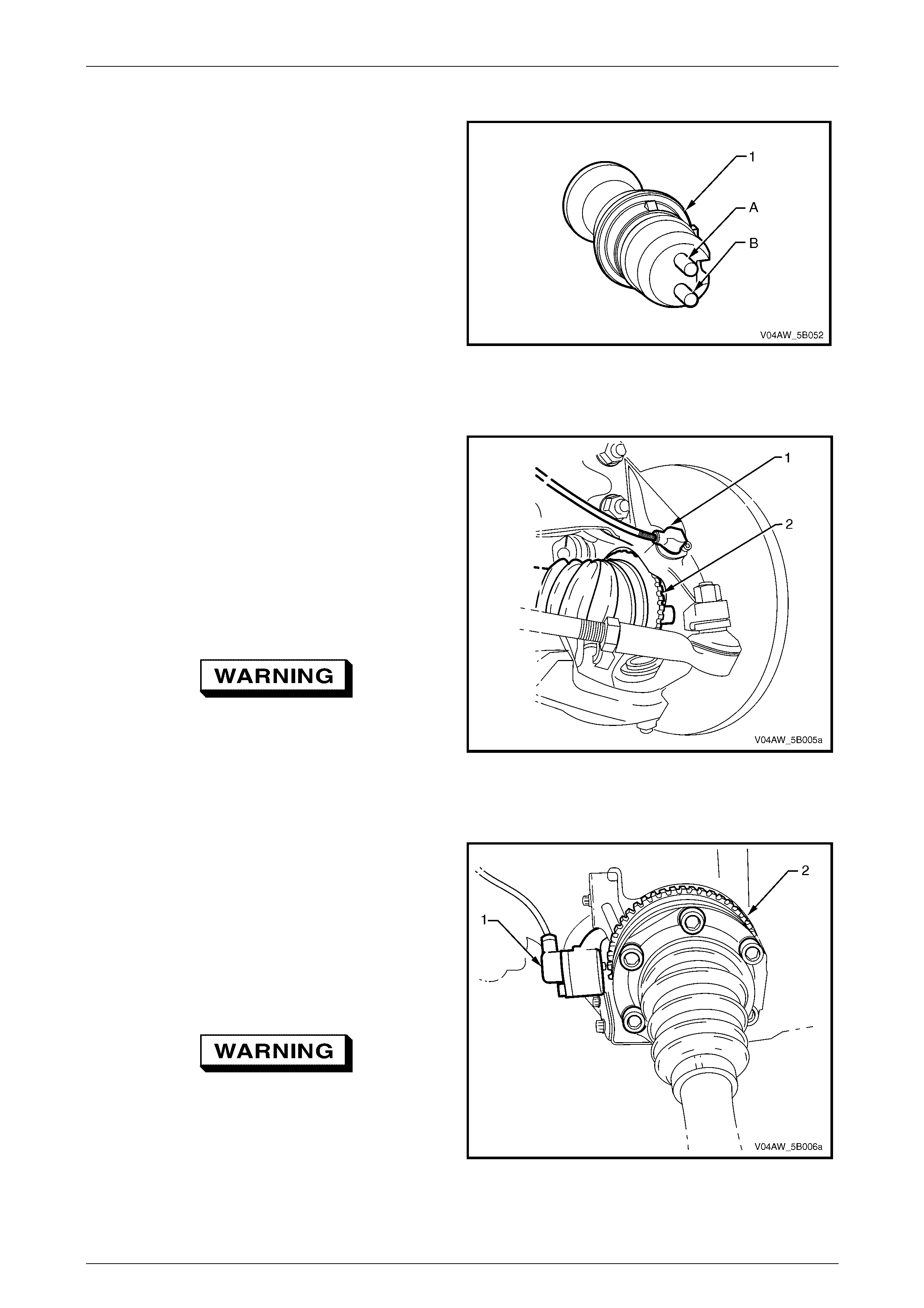
Front Wheel Speed Sensor
The front wheel speed sensor (1) in conjunction with a
pulse ring (2) generates an AC signal voltage. The
amplitude and frequency of the signal generated is
proportional to the wheel speed.
Signals generated by the front wheel speed sensor are
transmitted to the Electronic Control Unit (ECU). The ECU
uses this signal voltage to determine the rotational speed of
the front wheels.
The front wheel speed sensor pulse ring is a part of the
front driveshaft constant velocity joint assembly and is not
serviced separately. Refer to Section 4B2 Final Drive.
If the front constant velocity joint requires
replacement, the correct replacement part
must be installed. Otherwise, ABS-TCS
malfunction will occur. Figure 5B – 25
Rear Wheel Speed Sensors
The rear wheel speed sensor (1) in conjunction with a pulse
ring (2) generates an AC signal voltage. The amplitude and
frequency of the signal generated is proportional to the
wheel speed.
Signals generated by the rear wheel speed sensor are
transmitted to the ECU. The ECU uses this signal voltage to
determine the rotational speed of the front wheels.
The rear wheel speed sensor pulse ring is part of the final
drive inner axle flanges and is not serviced separately.
If the final drive inner axle flange requires
replacement, the correct replacement part
must be installed. Otherwise, ABS-TCS
malfunction will occur.
Figure 5B – 26
AW D ABS-TCS Page 5B–32
Page 5B–32
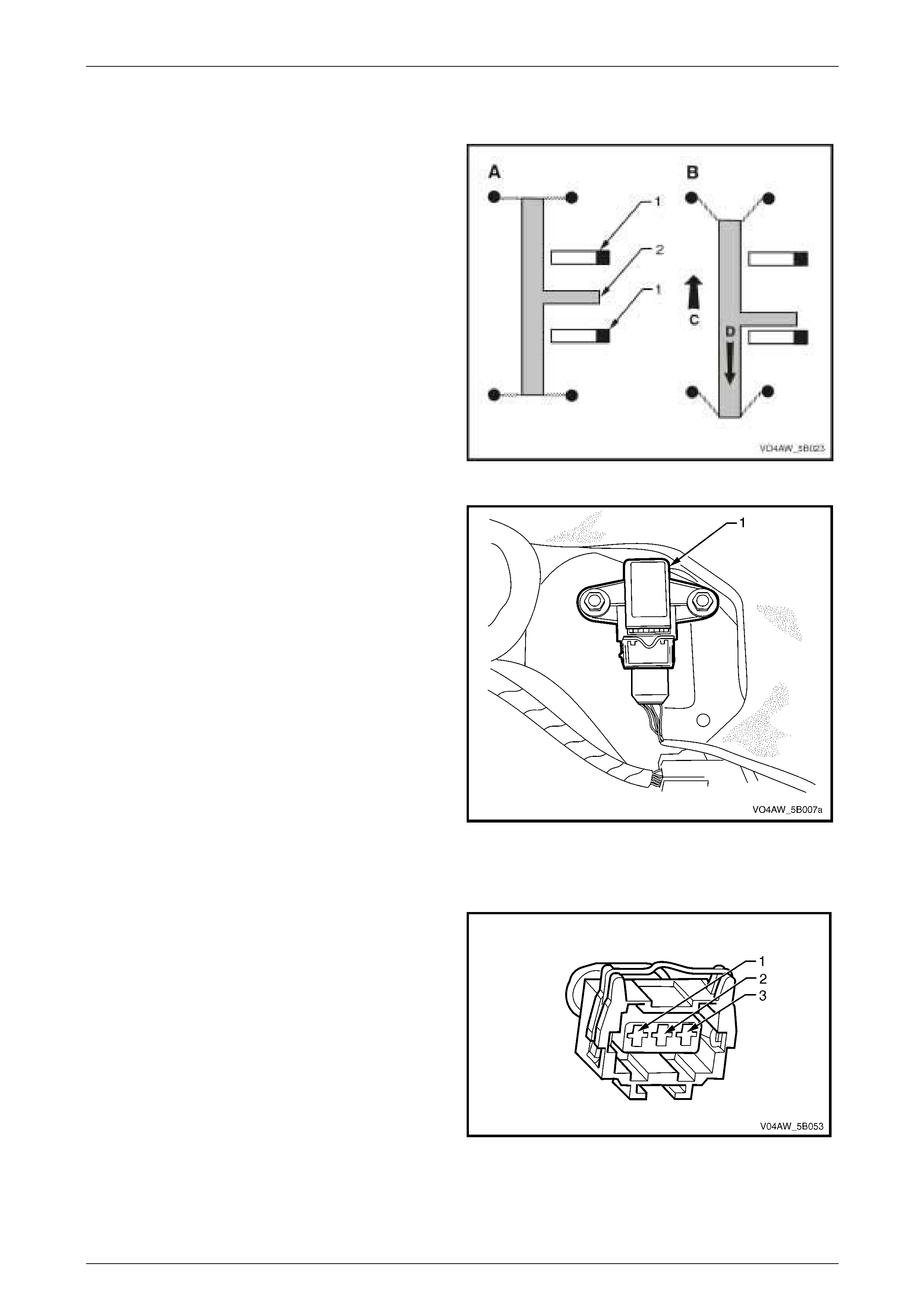
3.4 Longitudinal Accelerometer
The longitudinal accelerometer consists of differential
capacitors connected to the fixed side plates (1) and a
sprung mass (2) that moves in response to vehicle
acceleration (C).
When the vehicle is stationary (A), the distance between
the sprung mass and the two side plates are equal.
Therefore, the capacitance between the two capacitors are
the same and the longitudinal accelerometer signal voltage
is zero.
As the vehicle accelerates (B), the sprung mass moves
rearward (D). The capacitance between the two capacitors
changes causing the longitudinal accelerometer to produce
a signal voltage with an amplitude proportional to the
movement of the sprung mass.
The signal voltage from the accelerometer is proportional to
the vehicle level of acceleration or deceleration.
Figure 5B – 27
The Longitudinal Accelerometer (1) sends signal voltage,
which the ECU uses to determine the rate of vehicle
acceleration or deceleration. In addition, the longitudinal
accelerometer supports the calculation of the actual vehicle
speed when all four wheels are slipping.
In addition, the ECU monitors and evaluates the longitudinal
accelerometer signal voltage along with the wheel speed
sensor signal voltage to determine the uphill or downhill
gradient.
The longitudinal accelerometer aids the ECU to correctly
identify different driving situations and conditions to
enhance the vehicle's stability, steering control and traction
control.
Figure 5B – 28
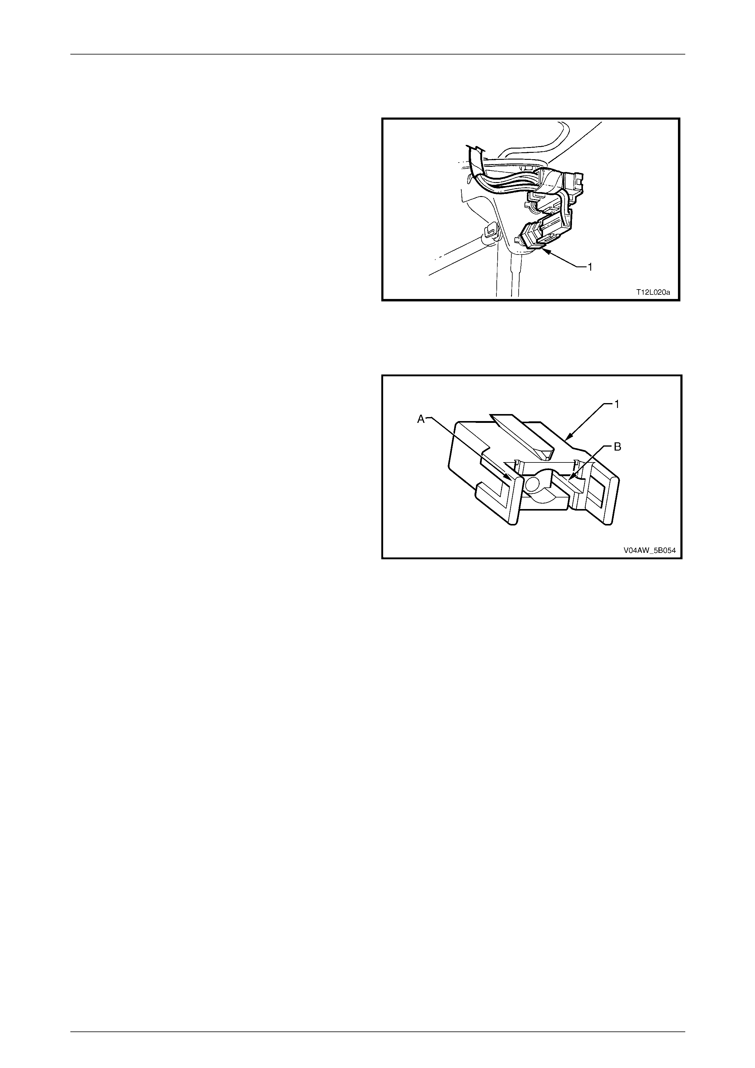
Longitudinal Accelerometer Wiring Connector
Legend
1 Longitudinal A ccelerometer Low Referenc e Ci rcuit 1338
2 Longitudinal A ccelerometer Signal Circ ui t 716
3 Longitudinal A ccelerometer 5 Volts Reference Circuit 1337
Figure 5B – 29
AW D ABS-TCS Page 5B–33
Page 5B–33
3.5 Stop Lamp Switch-A
The stop lamp switch A (1) is a normally open switch that
closes when the brake pedal is depressed.
The ECU uses the stop lamp switch signal voltage to
determine when the brakes pedal is depressed.
For stop lamp switch service operations, refer to
Section 12B Lighting System.
Figure 5B – 30
Stop Lamp Switch-A Wi ri ng Connect or
Legend
1 Stop Lamp Switch-A Wiri ng Connector
A Stop Lamp Switch Signal Vol tage Circuit 20
B Stop Lamp Switch Supply – Fuse F5 Circuit 640
Figure 5B – 31
AW D ABS-TCS Page 5B–34
Page 5B–34
3.6 AWD ABS – TCS Warning Display
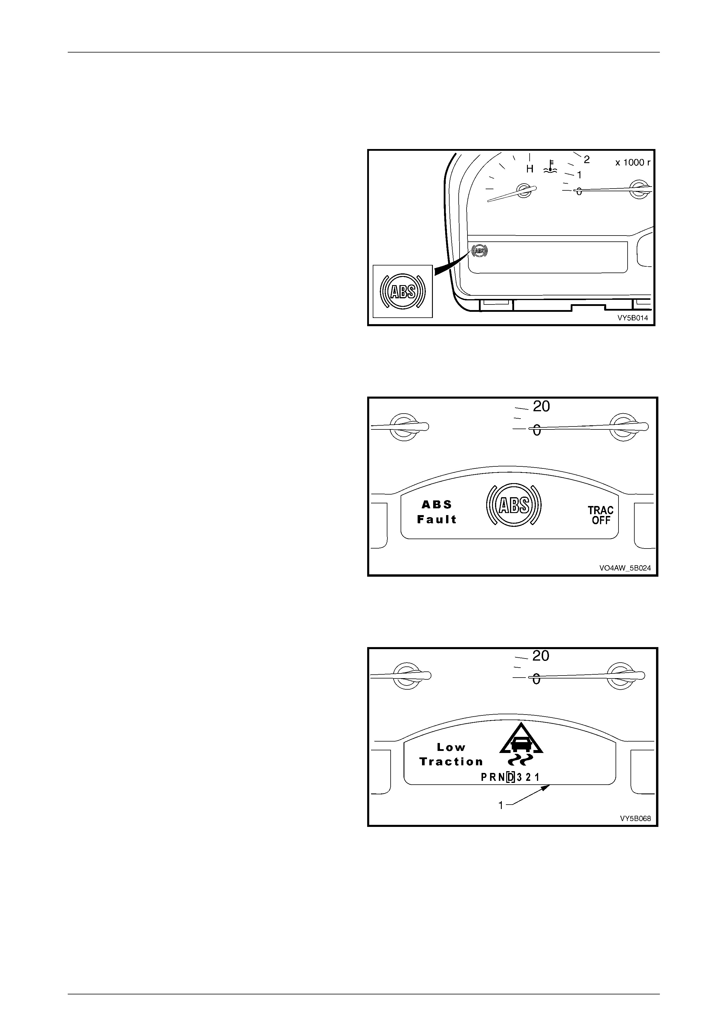
ABS Warning Lamp
The ABS wa rning lamp is located in the instrument cluster
and is a part of the driver warning system.
When the ignition is switched on, the ECU performs self-
test and the ABS warning lamp illuminates. The ABS lamp
should go out after the self-test or approximately 2 seconds.
If the ECU detects a fault in the ABS, the ABS lamp will stay
illuminated to warn the driver of the ABS fault.
Refer to Section 12C Instruments for further information on
the ABS warning lamp operation and diagnostic procedure.
Figure 5B – 32
ABS Fault / Trac Of f Warning Displ ay
If the ECU detects a fault in ABS, ABD or EBD System, the
ABS Fault, ABS Icon and TRAC OFF warning display
activates to warn the driver that ABS, ABD and EBD System
have been disabled. Refer to Section 12C, Instruments for
further information on the ABS Fault / Trac Off warning
display operation and diagnostic procedure.
Figure 5B – 33
Low Traction Warning Di spl ay
If the ECU detects a wheel spin condition and the brakes
are not applied, it switches to ABD Mode and activates the
LOW TRAC warning display to warn the driver of the
situation. Refer to Section 12C Instruments for further
information on the Low Traction warning display operation
and diagnostic procedure.
Figure 5B – 34
AW D ABS-TCS Page 5B–35
Page 5B–35
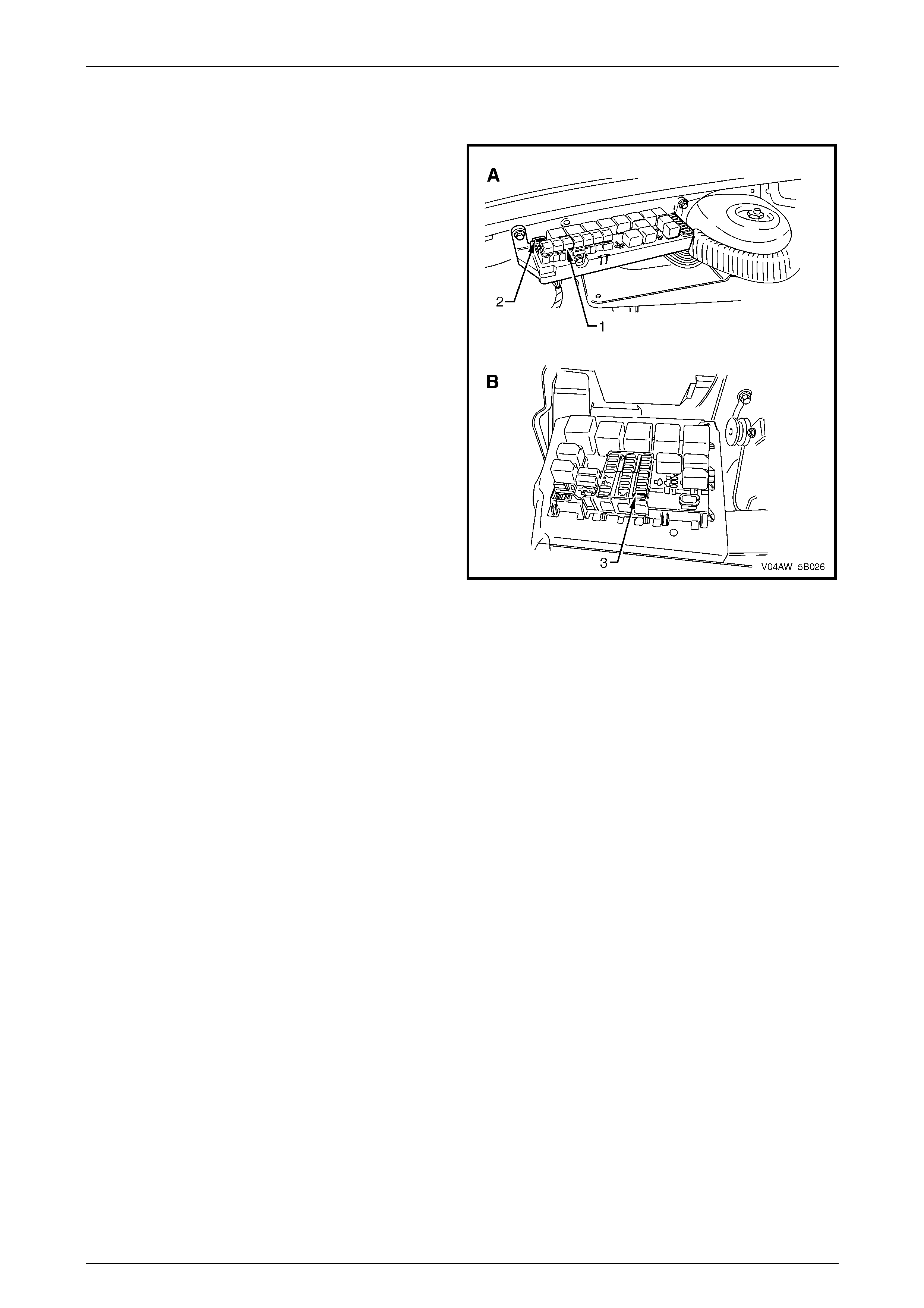
3.7 ABS-TCS Fuse Locations
The ABS-TCS fuse location are as follows:
• 50 Amp fusible link (1), F103 is located on the engine
compartment fuse and relay panel assembly (A).
• 25 Amp fuse (2), F36 is located on the engine
compartment fuse and relay panel assembly (A).
• 10 Amp fuse (3), F27 is located on the passenger
compartment fuse and relay panel assembly (B).
Figure 5B – 35

AW D ABS-TCS Page 5B–36
Page 5B–36
4 AWD ABS-TCS Diagnostics
General Information
The ABS-TCS diagnostic procedure is organised in a logical structure that begins with the ABS-TCS Main Diagnostic
Table. The Main Diagnostic Table provides the following information:
• Identification of the ECU ,
• Condition of the diagnostic circuit,
• Identification and status of the DTCs if present.
In addition, the Main Diagnostic Table will direct the service technician to the next logical step or diagnostic table, which
may again refer the service technician to the next logical step or diagnostic table. This process will continue until the
fault is located and rectified.
However, the diagnostic information covered in this Section covers fault conditions only in the ABS-TCS. If there are
fault conditions with the conventional braking system such as the following; these fault conditions must be corrected
before attempting to rectify any suspected ABS-TCS fault.
• Brake noise,
• Spongy brake pedal feel,
• Brake pedal or vehicle vibration during normal brake application,
• Brake pulling to one side,
• Parking brake problem.
Refer to Section 5A Service and Park Braking Systems for the diagnosis and repair procedure of the conventional
braking system.
4.1 Diagnostic Trouble Code (DTC) Tables
The diagnostic procedure is directed to the Diagnostic Trouble Code (DTC) Tables if there are DTCs currently stored in
the ECU.
The diagnostic tables are designed to locate a faulty circuit or component through a logic based on the process of
elimination. The tables are prepared with the understanding that the vehicle:
• Functioned correctly at the time of assembly,
• There are no multiple faults,
• The problem currently exists.
If there are multiple DTCs stored in the ECU, the diagnostic process must begin with the most likely DTC that may
trigger other DTCs. The following situation is an example of a DTC that may trigger other DTCs to set.
• If there is a battery supply voltage fault condition in the ECU, DTC C0896 Battery Voltage Out of Range may set.
• Insufficient battery supply voltage to an ABS-TCS component such as a solenoid valve coil may cause
incorrect hydraulic modulator operation. This condition will cause incorrect ABS-TCS operation and may
trigger DTC C0121 to set.
• A battery supply voltage to the ECU that is too high may cause damage to other ABS-TCS components. If
this charging system fault condition is not rectified and an ABS-TCS component is replaced, premature
failure of the replacement component may occur.
Therefore, knowledge of the ABS-TCS and Tech 2 Limitations are important to reduce diagnostic time and to prevent
misdiagnosis. Refer to 5.1 Diagnostic Requirements, Precautions and Preliminary Checks and 4.3 Tech 2 ECU
Diagnostic Tests.
AW D ABS-TCS Page 5B–37
Page 5B–37
4.2 Diagnostic Trouble Codes (DTCs)
The ECU performs a self-test that detects and isolates ABS-TCS faults (refer to 3.1 ECU Self-test Initialisation
Sequence). When a fault is detected, the ECU will log a Diagnostic Trouble Code (DTC) that represents the fault
detected. The DTCs stored in the ECU may be accessed using Tech 2, refer to Section 0C Tech 2 for information on
Tech 2.
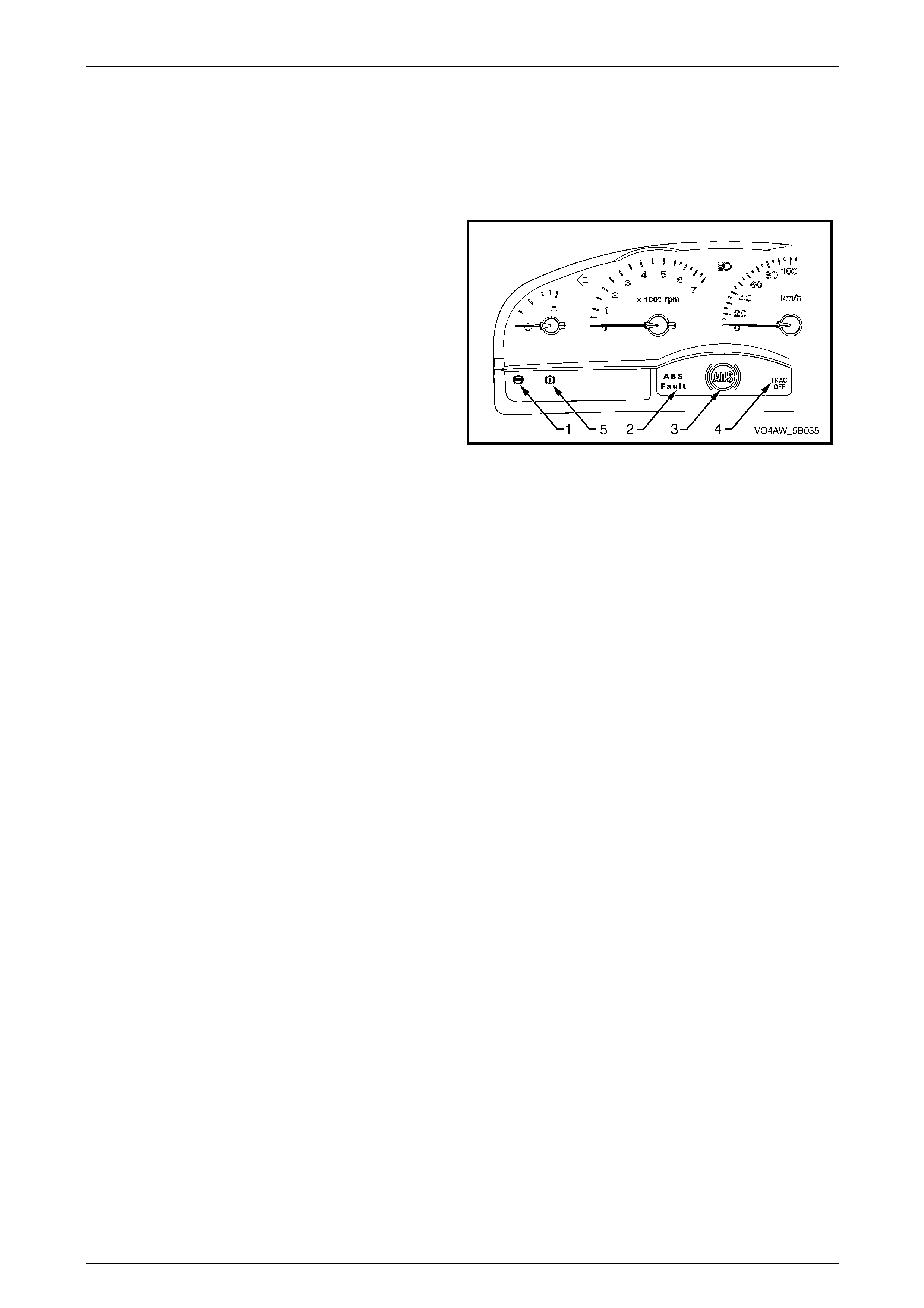
NOTE
To warn the driver that there is a fault in the ABS
and/or TCS System and that the ABS and/or
TCS is currently disabled, the ECU sends a
signal to the following instrument cluster warning
lamps or icons to activate:
• ABS warning lamp (1)
• ABS fault (2)
• ABS icon (3)
• TRAC OFF (4)
• Parking brake/brake fail warning lamp (5)
Refer to Section 12C, for further information on
the braking system warning lamps and icon.
Figure 5B – 36
Status of DTCs
The ECU designates the DTCs logged into a Current or History DTC.
Current DTCs
If the fault condition that triggers the DTC is present during the last ECU self-diagnostics, that DTC will be designated as
a current DTC.
History DTCs
If the fault condition that triggers the DTC is not present during the last ECU self-test, that DTC will be designated as a
Histo r y DTC.
Conditions f or Clearing DTCs
• If there is no DTC logged in the current ECU self-test, the current DTC will be cleared.
• If there is no DTC logged after the last ECU self-diagnostics, the ECU deactivates the MFD ABS warning display.
• If there is no DTC logged after 100 consecutive drive cycles, the history DTC will be cleared.
• Use Tech 2 to clear the DTC.

AW D ABS-TCS Page 5B–38
Page 5B–38
4.3 Tech 2 ECU Diagnostic Tests
NOTE
Refer to Section 0C TECH 2 and the Tech 2
Users Manual for detailed information and
instruction regarding the use of Tech 2.
Tech 2 Limitations
Some DTCs trigger other DTCs to set, which cause Tech 2 to display multiple DTCs. Therefore, in those situations,
Tech 2 may display more DTCs than what is needed to rectify a fault.
In addition, when Tech 2 is displaying an ECU Output Function, it displays only the command given by the ECU. If a
connector is disconnected or if a solenoid valve is faulty, that fault will not be registered in the ECU Output Function.
Tech 2 does not verify if the command action took place.
The service technician must understand the system being diagnosed as well as the correct use and limitations of Tech 2
to be able to perform diagnostic procedures efficiently and successfully.
Tech 2 Intermittent Faul t Tests
The following are lists of Tech 2 diagnostic tests that may be used to diagnose intermittent faults:
• Wiggle test the suspected ABS-TCS component wiring harness and connectors while observing the Tech 2
operating parameters of the circuit being tested. If the Tech 2 read-out fluctuates during this procedure, check the
wiring harness circuit for loose connection.
• Road test the vehicle in the conditions that triggers the intermittent fault while an assistant observes the suspected
Tech 2 operating parameter data.
• Capture and store data in the Snapshot mode when the fault occurs. The stored data may be played back at a
slower rate to aid in diagnostics. Refer to the Tech 2 User Instructions for more information on the Snapshot
function.
• Operate suspected ABS-TCS components to test their operation using the Tech 2 Output Control Data.

AW D ABS-TCS Page 5B–39
Page 5B–39
Tech 2 Data List
The Tech 2 ABS-TCS Data List contains the ABS-TCS operating parameters that may be used to analyse the ABS-TCS
operating parameters of the vehicle being diagnosed.
This enables the technician to compare the operating parameter of the vehicle being diagnosed to the typical data value
of a known good vehicle.
NOTE
The Tech 2 Data List Typical Data Values are
obtained from a properly operating vehicle under
the following conditions;
• Ignition switched on.
• Engine not running,
• Vehicle is stationary.
Tech 2 Data List Table
Tech 2 Parameter Units Displayed Typical Data Value
Battery Voltage Volts B+
ABS Active Yes / No No
EBD Active (Electronic Brake-force Distribution) Yes / No No
EBD Disabled (Electronic Brake-force Distribution) Yes / No No
Valve Relay Inactive / Active Active
Motor Relay Inactive / Active Inactive
Brake Switch Inactive / Active Inactive
Front Left Wheel Speed km/h 0
Front Right Wheel Speed km/h 0
Rear Left Wheel Speed km/h 0
Rear Right Wheel Speed km/h 0
Front Left Inlet Valve Inactive / Active Inactive
Front Left Outlet Valve Inactive / Active Inactive
Front Right Inlet Valve Inactive / Active Inactive
Front Right Outlet Valve Inactive / Active Inactive
Rear Left Inlet Valve Inactive / Active Inactive
Rear Left Outlet Valve Inactive / Active Inactive
Rear Right Inlet Valve Inactive / Active Inactive
Rear Right Outlet Valve Inactive / Active Inactive
FL/FR TC Priming Valve (Front Left/Front Right) Inactive / Active Inactive
FL/FR TC Switch Over Valve (Front Left/Front Right) Inactive / Active Inactive
RL/RR TC Priming Valve (Rear Left/ Rear Right) Inactive / Active Inactive
RL/RR TC Switch Over Valve (Rear Left/ Rear Right) Inactive / Active Inactive

AW D ABS-TCS Page 5B–40
Page 5B–40
5 AWD ABS-TCS Diagnostic
Starting Point
5.1 Diagnostic Requirements, Precautions
and Preliminary Checks
Basic Knowledge Requi red
A lack of basic understanding regarding
electronics, electrical wiring circuits and use
of electrical circuit testing tools when
performing the ABS-TCS diagnostic
procedures could result in incorrect
diagnostic results or damage to components.
A general understanding of basic electronics, electrical wiring circuits and the correct use of the basic ABS-TCS System
electrical circuit testing tools is required to perform the diagnostic procedures detailed in this Section. Refer to
Section 12P Wiring Diagrams .
In addition, a general understanding of the ABS-TCS and its component operation is essential to prevent misdiagnosis
and component damage.
Basic Diagnosti c Tools Required
Use of incorrect electrical circuit diagnostic
tools when performing the ABS-TCS
diagnostic procedures could result in
incorrect diagnostic results or damage to
components.
The following electrical circuit testing tools are required to perform the diagnostic procedures detailed in this Section.
• Tech 2, refer to Section 0C Tech 2.
• Test light, refer to Section 12P Wiring Diagrams.
• Digital multimeter with 10 mega ohms impedance, refer to Section 12P Wiring Diagrams.
• Connector test adapter kit Tool No. J35616-A.

AW D ABS-TCS Page 5B–41
Page 5B–41
Diagnostic Precaut ions
In addition to the safety and precautionary
measures listed in the Service Operation
Safety and Precautionary Measures, (refer to
9.1 Safety and Precautionary Measures) the
following Diagnostic Precautions must be
observed when performing any ABS-TCS
diagnostic procedure:
1 If there is a fault condition in the conventional braking system, rectify that fault condition before proceeding with
the ABS-TCS diagnostics.
2 Use only the test equipment specified in the diagnostic tables, other test equipment may either give incorrect
results or may damage good components.
3 The vehicle drive wheels must be chocked and the parking brake firmly applied while checking any system.
4 Do not clear any DTCs unless instructed.
5 The fault must be present when using the Diagnostic Trouble Code (DTC) Diagnostic Tables. Otherwise,
misdiagnosis or replacement of good parts may occur.
6 Always use connector adaptors such as those contained in Connector test adapter kit Tool No. J35616-A to
prevent connector terminal damage.
7 Thorough inspection of the wiring circuits and connectors that are part of diagnostic procedure must be performed,
otherwise misdiagnosis may occur.
8 Inspect the electrical circuitry or connector terminals that are suspected to be causing the complaint for the
following conditions:
• Backed-out connector terminals,
• Improper wiring connector mating,
• Broken wiring connector locks,
• Damaged connector terminals, and
• Physical damage to the wiring harness.
9 Before replacing a component, inspect its connector terminal for corrosion or deformation that may cause the fault
condition.
10 If Tech 2 was used for diagnosis, disconnect it from the DLC and switch the ignition off for at least 10 seconds
before road testing. This is necessary to reset the ABS/TCS control module as it is disabled during most Tech 2
diagnostic procedures.
11 After completing the required diagnostic and repair operations, road test the vehicle to ensure proper ABS/TCS
operation.

AW D ABS-TCS Page 5B–42
Page 5B–42
Prelimi nary Checks
The ABS-TCS Preliminary Checks is an examination of easily accessible components that could cause problems with
the ABS-TCS. This visual and physical inspection procedure may quickly identify the fault condition and eliminate the
need for additional diagnosis.
• Refer to Service Techlines for relevant information regarding the fault condition.
• Ensure that only the recommended tyres and wheel size are fitted to the vehicle.
• Check the hydraulic modulator for external leaks.
• Check the ABS fuses. Refer to 3.7 ABS-TCS Fuse Locations.
• Check the ABS-TCS warning lamp fuse and stop lamp fuse. Refer to Section 12P Wiring Diagrams.
• Ensure that the battery is fully charged.
• Check the battery connections for corrosion or a loose terminal.
• Perform a visual and physical inspection of the following ECU system:
• ABS-TCS component wiring harness and term inals for proper connections, pinches or cuts.
• Wiring harness routing which may be positioned very close to a high voltage or high current device such as
the following:
• Secondary ignition components
• Motors and generators
NOTE
High voltage or high current devices may induce
electrical noise on a circuit, which can interfere
with normal circuit operation.
• ABS-TCS related components for poor mating of the connector halves or a terminal not fully seated in the
connector body.
• ABS-TCS components are sensitive to Electro-magnetic Interference (EMI). Check for incorrect aftermarket
theft deterrent devices, lights or mobile phone installations if an intermittent malfunction is suspected.

AW D ABS-TCS Page 5B–43
Page 5B–43
5.2 AWD ABS-TCS Main Diagnostic Table
Step Action Yes No
1 Did you meet the basic diagnostic requirements, read the diagnostic
precautions and performed the preliminary checks listed in 5.1
Diagnostic Requirements, Precautions and Preliminary Checks?
Go to Step 2
Refer to
5.1 Diagnostic
Requirements,
Precautions and
Preliminary Checks.
2 1 Switch on the ignition wi th the engine not running.
2 Using Tech 2, attempt to communicate with the ECU , BCM,
PCM, PIM and the Instrument Cluster Assembly.
3 View all DTCs.
4 Record DTCs set by each module.
Did any of the control modules fail to communicate?
Refer to
4.2 Serial Data
Communication in
Section 12J. Go to Step 3
3 Did Tech 2 display any Serial Data Communication related DTCs? Refer to
8 Diagnostic Link
Communication
Diagnostics Go to Step 4
4 Did Tech 2 display any DTCs? If there are multiple
DTC listed, begin
diagnosing the DTC
that can trigger
other DTCs to set or
to a DTC that is
most likely to cause
the customer's
concern.
Refer to 6 AWD
ABS-TCS
Intermittent
Conditions
When all diagnosis and repairs are completed, check the system for correct operation.

AW D ABS-TCS Page 5B–44
Page 5B–44
6 AWD ABS-TCS
Intermittent Condi tions
6.1 Description
A fault condition is intermittent if one of the following exists:
• The fault condition is not always present.
• The fault condition cannot be presently duplicated.
• There is no Current DTC but a History DTC is stored.

AW D ABS-TCS Page 5B–45
Page 5B–45
6.2 AWD ABS-TCS Intermittent Conditions
Diagnostic Table
Checks Actions
Preliminary • Perform the Preliminary Checks. Refer to 5.1 Diagnostic Requirements,
Precautions and Preliminary Checks.
• Gather information from the customer regarding the conditions that trigger the
intermittent fault such as:
• At what vehicle speed range does the fault occur?
• Does the fault occur when operating aftermarket electrical equipment inside
the vehicle?
• Does the fault occur on rough roads or in wet road conditions?
• If a wheel speed sensor fault condition is present only during wet road
conditions, inspect the wheel speed sensor electrical circuit for signs of
water intrusion. If the DTC is not current, simulate the effect of a wet road
condition by performing the following:
1 Mix two teaspoons of salt with 35 ml water.
2 Spray the saltwater solution to the suspected area.
3 Road test the vehicle at various road conditions.
4 Accelerate the vehicle at speed above 40 km/h for at least 30
seconds.
5 If the suspected wheel speed sensor DTC sets, replace the suspected
wheel speed sensor.
Harness/ Connector Install Tech 2 and perform the Tech 2 Intermittent Fault Tests. Refer to 4.3 ECU
Diagnostic Tests.
Malfunction Indicator Lamp The following condition may cause an intermittent Malfunction Indicator Lamp fault with
no DTC listed.
• Electromagnetic Interference (EMI) caused by a faulty relay.
• Incorrect installation of aftermarket electrical equipment such as the following:
• Mobile phones
• Theft deterrent alarms
• Lights
• Radio equipment
• Malfunction Indicator Lamp (MIL) circuit is intermittently shorted to ground.
• ECU ground connections are loose.
Wheel Speed Sensors • Visually inspect wheel speed sensors and pulse rings for looseness, damage,
foreign material accumulation and proper mounting. Replace damaged
components, remove any foreign material and/or properly attach loose
components.
• Check for correct wiring harness routing of the front wheel speed sensor.
Ensure that it is not positioned too close to spark plug leads. Refer to Section
6C3, Ignition System for the correct spark plug lead routing.
• Measure the resistance of the spark plug leads, refer to Section 6C3 Ignition
System. Replace faulty spark plug leads.
• With the aid of an assistant, monitor the Tech 2 wheel speed sensor data display
while test driving the vehicle. Check for any wheel speed sensor that displays
erratic speed range.

AW D ABS-TCS Page 5B–46
Page 5B–46
Checks Actions
Additional Tests • Incorrect installation of aftermarket electrical equipment such as the following:
• Mobile phones
• Theft deterrent alarms
• Lights
• Radio equipment
• Electro-magnetic Interference (EMI) caused by a faulty relay. The fault is triggered
when the relay or solenoid is activated.
• Test the A/C compressor clutch and some relays that contain a clamping diode or
resistor.
• Test the generator for a faulty rectifier bridge that may allow the A/C noise into the
ECU electrical circuit
When all diagnosis and repairs are completed, check the system for correct operation.

AW D ABS-TCS Page 5B–47
Page 5B–47
7 AWD ABS-TCS DTC Tables
7.1 DTC C0035 – Front Left Wheel Speed
Sensor Short or Open Circuit
Circuit Descri ption
The ECU supplies ground to the wheel speed sensor low reference circuit 873.
The wheel speed sensor in conjunction with a pulse ring generates an AC signal voltage. The amplitude and frequency
of the signal generated is proportional to the wheel speed. The ECU monitors each wheel speed sensor signal circuit to
determine the speed of each wheel.
If the ECU detects a short to voltage or an open circuit condition in the front left wheel speed sensor signal circuit 830,
and/or low reference circuit 873 DTC C0035 sets.
Figure 5B – 37
Diagnostic Aids
Conditions for Running DTC C0035
The ignition is switched on.
Conditions for Setting DTC C0035
If there is a short to voltage or open circuit fault condition in the front left wheel speed sensor signal circuit 830 or low
reference circuit 873.
Action Taken When DTC C0035 Sets
• The ECU disables the ABS-TCS for the duration of the ignition cycle.
• The ABS wa rning lam p , the ABS warning icon and the trac-off icon activates.
• The brake failure lamp activates.
Additional information
• Refer to 4.2 DTCs for information on the conditions for clearing DTCs.
• High voltage or high current devices such as spark plugs and spark plug wires may induce electrical noise on the
front left wheel speed sensor circuit. This electrical noise can interfere with normal wheel speed sensor operation.
Ensure that the wheel speed sensor wiring harness is routed away from these high voltage or high current
devices.
• For intermittent fault conditions, refer to 6 Intermittent Conditions.
• Refer to Figure 5B – 38 for ECU and wheel speed sensor connector illustrations.

AW D ABS-TCS Page 5B–48
Page 5B–48
Figure 5B – 38
Test Description
Step 2 This Step verifies if the fault is currently present.
Step 3 This Step tests the front left wheel speed sensor internal circuitry.
Step 5 This Step tests the front left wheel speed sensor output voltage capacity.

AW D ABS-TCS Page 5B–49
Page 5B–49
DTC C0035 Diagnostic Table
Step Action Value(s) Yes No
1 Was the ABS-TCS Main Diagnostic Table performed? – Go to Step 2 Refer to
5.5 ABS-TCS Ma in
Diagnostic Starting
Point.
2 1 Using Tech 2, observe the Freeze Frame / Failure
Record for this DTC.
2 Switch off the ignition for 10 seconds.
3 Road test the vehicle within the conditions for
running this DTC or within the conditions in the
Freeze Frame/Failure Record.
Did DTC C0035 fail this ignition?
–
Go to Step 3
Refer to DTC C0035
Additional
Information.
3 1 Disconnect the front left wheel speed sensor
connector.
2 Using a digital multimeter, measure the resistance
across the wheel speed sensor connector.
Is the resistance within the specified range? 1.4 - 1.8 kΩ
@ 20°c Go to Step 4 Go to Step 9
4 1 Raise the front of the vehicle and support on
safety stands. Refer to Section 0A General
Information for location of the jacking points.
2 Connect an oscilloscope to the front left wheel
speed sensor connector terminals.
3 Spin the front left wheel.
4 Observe the wheel speed sensor output signal
pattern. Refer to 3.3 Wheel Speed Sensors.
NOTE
If an oscilloscope is not available, perform
the following visual inspection:
• Inspect the front left wheel speed sensor
pulse ring for damaged teeth.
• While rotating the front left wheel, check
the wheel speed sensor alignment to the
pulse ring.
• Check the front left wheel speed sensor
run-out.
• Check the front left wheel speed sensor
or pulse ring for dirt or other
contaminants that may affect its
operation.
Was any fault found and rectified?
–
Go to Step 11 Go to Step 5
5 1 Using a digital multimeter, measure the AC signal
voltage across the front left wheel speed sensor
connector while spinning the front left wheel.
Is the voltage more than the specified value?
100 mV
Go to Step 6 Go to Step 9
6 Inspect for poor wiring connection at the front left wheel
speed sensor wiring connector. Refer to Section 12P
Wiring Diagrams for information on testing wiring
circuits.
Was any fault found and rectified?
–
Go to Step 11 Go to Step 7

AW D ABS-TCS Page 5B–50
Page 5B–50
Step Action Value(s) Yes No
7 Test the wheel speed sensor signal circuit 830 and low
reference circuit 873 for a high resistance, open circuit,
short to voltage, short to ground or shorted together
condition. Refer to Section 12P Wiring Diagrams for
information on wiring circuit testing and repair.
Was any fault found and rectified?
–
Go to Step 11 Go to Step 8
8 Inspect for poor connections at the ECU wiring
connector. Refer to Section 12P Wiring Diagrams for
information on wiring circuit testing and repair.
Was any fault found and rectified?
–
Go to Step 11 Go to Step 10
9 Replace the front left wheel speed sensor. Refer to
9.5 Front Left Wheel Speed Sensor.
Was the repair completed? – Go to Step 11 –
10 Replace the ECU . Refer to 9.3 ECU /hydraulic
modulator.
Was the repair completed? – Go to Step 11 –
11 1 Using Tech 2, clear the DTCs.
2 Switch off the ignition for 10 seconds.
3 Operate the vehicle within the conditions for
running DTC C0035.
Did DTC C0035 fail this ignition?
–
Go to Step 2 Go to Step 12
12 Using Tech 2, select the DTC display function.
Are there any DTC displayed? – Go to the
appropriate DTC
Table. System OK
When all diagnosis and repairs are completed, check the system for correct operation.

AW D ABS-TCS Page 5B–51
Page 5B–51
7.2 DTC C0036 – Front Left Wheel Speed
Sensor Signal Correlation
Circuit Descri ption
The ECU supplies ground to the front left wheel speed sensor low reference circuit 873.
The wheel speed sensor in conjunction with a pulse ring generates an AC signal voltage. The amplitude and frequency
of the signal generated is proportional to the wheel speed. The ECU monitors the wheel speed sensor signal voltage to
determine the wheel speed of each wheel.
DTC C0036 sets if the ECU detects a plausibility error and/or a short to ground condition in the front left wheel speed
sensor signal circuit 830 and there is a deviation of more than 6 km/h between the front left wheel speed and reference
vehicle speed.
Figure 5B – 39
Diagnostic Aids
Conditions for Running DTC C0036
• The ignition is switched on.
• Vehicle speed is approximately over 40 km/h.
• Brake pedal is not depressed.
• ABS-TCS is not active.
Conditions for Setting DTC C0036
If the front left wheel speed sensor signal circuit 830 is shorted to ground and the ECU detects a deviation of more than
6 km/h between the front left wheel speed and the reference vehicle speed.
Action Taken when DTC C0036 Sets
• The ECU disables the ABS-TCS for the duration of the ignition cycle.
• The ABS wa rning lam p , the ABS warning icon and the trac-off icon activates.
• The brake failure lamp activates.
Additional information
• Refer to 4.2 DTCs for information on the conditions for clearing DTCs.
• High voltage or high current devices such as spark plugs and spark plug wires may induce electrical noise on the
front left wheel speed sensor circuit. This electrical noise can interfere with normal wheel speed sensor operation.
Ensure that the wheel speed sensor wiring harness is routed away from these high voltage or high current
devices.
• For intermittent fault conditions, refer to 6 Intermittent Conditions.
• Refer to Figure 5B – 40 for the ECU and wheel speed sensor connector illustrations.

AW D ABS-TCS Page 5B–52
Page 5B–52
Figure 5B – 40
Test Description
Step 2 This Step verifies if the fault is currently present.
Step 3 This Step tests the front left wheel speed sensor internal circuitry.
Step 5 This Step tests the front left wheel speed sensor output voltage capacity.

AW D ABS-TCS Page 5B–53
Page 5B–53
DTC C0036 Diagnostic Table
Step Action Value(s) Yes No
1 Was the ABS-TCS Main Diagnostic Table performed? – Go to Step 2 Refer to
5.5 ABS-TCS Ma in
Diagnostic Starting
Point.
2 1 Using Tech 2, observe the Freeze Frame / Failure
Record for this DTC
2 Switch off the ignition for 10 seconds.
3 Road test the vehicle within the conditions for
running this DTC or within the conditions in the
Freeze Frame/Failure Record.
Did DTC C0036 fail this ignition?
–
Go to Step 3
Refer to DTC C0036
Additional
Information.
3 1 Disconnect the front left wheel speed sensor
connector.
2 Using a digital multimeter, measure the resistance
across the wheel speed sensor connector.
Is the resistance within the specified range? 1.4 - 1.8 kΩ
@ 20°c Go to Step 4 Go to Step 9
4 1 Raise the front of the vehicle and support on
safety stands. Refer to Section 0A General
Information for location of the jacking points.
2 Connect an oscilloscope to the front left wheel
speed sensor connector terminals.
3 Spin the front left wheel.
4 Observe the wheel speed sensor output signal
pattern. Refer to 3.3 Wheel Speed Sensors.
NOTE
If an oscilloscope is not available, perform
the following visual inspection:
• Inspect the front left wheel speed sensor
pulse ring for damaged teeth
• While rotating the front left wheel, check
the wheel speed sensor alignment to the
pulse ring.
• Check the front left wheel speed sensor
run-out.
• Check the front left wheel speed sensor
or pulse ring for dirt or other
contaminants that may affect its
operation.
Was any fault found and rectified?
–
Go to Step 11 Go to Step 5
5 1 Using a digital multimeter, measure the AC signal
voltage across the front left wheel speed sensor
connector while spinning the front left wheel.
Is the voltage more than the specified value? 100 mV Go to Step 6 Go to Step 9
6 Inspect for poor wiring connection at the front left wheel
speed sensor wiring connector. Refer to Section 12P
Wiring Diagrams for information on testing wiring
circuits.
Was any fault found and rectified?
–
Go to Step 11 Go to Step 7

AW D ABS-TCS Page 5B–54
Page 5B–54
Step Action Value(s) Yes No
7 Test the wheel speed sensor signal circuit 830 and low
reference circuit 873 for a high resistance, open circuit,
short to voltage, short to ground or shorted together
condition. Refer to Section 12P Wiring Diagrams for
information on wiring circuit testing and repair.
Was any fault found and rectified?
–
Go to Step 11 Go to Step 8
8 Inspect for poor connections at the ECU wiring
connector. Refer to Section 12P Wiring Diagrams for
information on wiring circuit testing and repair.
Was any fault found and rectified?
–
Go to Step 11 Go to Step 10
9 Replace the front left wheel speed sensor. Refer to
9.5 Front Left Wheel Speed Sensor.
Was the repair completed? – Go to Step 11 –
1 Replace the ECU . Refer to 9.3 ECU /hydraulic
modulator.
Was the repair completed? – Go to Step 11 –
11 1 Using Tech 2, clear the DTCs.
2 Switch off the ignition for 10 seconds.
3 Operate the vehicle within the conditions for
running DTC C0036.
Did DTC C0036 fail this ignition?
–
Go to Step 2 Go to Step 12
12 Using Tech 2, select the DTC display function.
Are there any DTC displayed? – Go to the
appropriate
DTC Table. System OK
When all diagnosis and repairs are completed, check the system for correct operation.

AW D ABS-TCS Page 5B–55
Page 5B–55
7.3 DTC C0040 – Front Right Wheel Speed
Sensor Short or Open Circuit
Circuit Descri ption
The ECU supplies ground to the front right wheel speed sensor low reference circuit 833.
The wheel speed sensor in conjunction with a pulse ring generates an AC signal voltage. The amplitude and frequency
of the signal generated is proportional to the wheel speed. The ECU monitors each wheel speed sensor signal voltage
to determine the speed of each wheel.
If the ECU detects a short to voltage or an open circuit condition in the front right wheel speed sensor signal circuit 872,
and/or low reference circuit 833 DTC C0040 sets.
Figure 5B – 41
Diagnostic Aids
Conditions for Running DTC C0040
The ignition is switched on.
Conditions for Setting DTC C0040
If there is a short to voltage or open circuit fault condition in the front right wheel speed sensor signal circuit 872 or low
reference circuit 833.
Action Taken When DTC C0040 Sets
• The ECU disables the ABS-TCS for the duration of the ignition cycle.
• The ABS wa rning lam p , the ABS warning icon and the trac-off icon activates.
• The brake failure lamp activates.
Additional information
• Refer to 4.2 DTCs for information on the conditions for clearing DTCs.
• High voltage or high current devices such as spark plugs and spark plug wires may induce electrical noise on the
wheel speed sensor circuit. This electrical noise can interfere with normal wheel speed sensor operation. Ensure
that the front right wheel speed sensor wiring harness is routed away from these high voltage or high current
devices.
• For intermittent fault conditions, refer to 6 Intermittent Conditions.
• Refer to Figure 5B – 42 for the ECU and wheel speed sensor connector illustrations.

AW D ABS-TCS Page 5B–56
Page 5B–56
Figure 5B – 42
Test Description
Step 2 This Step verifies if the fault is currently present.
Step 3 This Step tests the front right wheel speed sensor internal circuitry.
Step 5 This Step tests the front right wheel speed sensor output voltage capacity.

AW D ABS-TCS Page 5B–57
Page 5B–57
DTC C0040 Diagnostic Table
Step Action Value(s) Yes No
1 Was the ABS-TCS Main Diagnostic Table performed? – Go to Step 2 Refer to
5.5 ABS-TCS Ma in
Diagnostic Starting
Point.
2 1 Using Tech 2, observe the Freeze Frame / Failure
Record for this DTC.
2 Switch off the ignition for 10 seconds.
3 Road test the vehicle within the conditions for
running this DTC or within the conditions in the
Freeze Frame/Failure Record.
Did DTC C0040 fail this ignition?
–
Go to Step 3
Refer to DTC C0040
Additional
Information.
3 1 Disconnect the front right wheel speed sensor
connector.
2 Using a digital multimeter, measure the resistance
across the wheel speed sensor connector.
Is the resistance within the specified range? 1.4 - 1.8 kΩ
@ 20°c Go to Step 4 Go to Step 9
4 1 Raise the front of the vehicle and support on
safety stands. Refer to Section 0A General
Information for location of the jacking points.
2 Connect an oscilloscope to the front right wheel
speed sensor connector terminals.
3 Spin the front right wheel.
4 Observe the wheel speed sensor output signal
pattern. Refer to 3.3 Wheel Speed Sensors.
NOTE
If an oscilloscope is not available, perform
the following visual inspection:
• Inspect the front right wheel speed
sensor pulse ring for damaged teeth.
• While rotating the front right wheel,
check the wheel speed sensor alignment
to the pulse ring.
• Check the front right wheel speed
sensor run-out.
• Check the front right wheel speed
sensor or pulse ring for dirt or other
contaminants that may affect its
operation.
Was any fault found and rectified?
–
Go to Step 11 Go to Step 5
5 1 Using a digital multimeter, measure the AC signal
voltage across the front right wheel speed sensor
connector while spinning the front right wheel.
Is the voltage more than the specified value? 100 mV Go to Step 6 Go to Step 9
6 Inspect for poor wiring connection at the front right
wheel speed sensor wiring connector. Refer to Section
12P Wiring Diagrams for information on testing wiring
circuits.
Was any fault found and rectified?
–
Go to Step 11 Go to Step 7

AW D ABS-TCS Page 5B–58
Page 5B–58
Step Action Value(s) Yes No
7 Test the front right wheel speed sensor signal circuit
872 and low reference circuit 833 for a high resistance,
open circuit, short to voltage, short to ground or shorted
together condition. Refer to Section 12P Wiring
Diagrams for information on wiring circuit testing and
repair.
Was any fault found and rectified?
–
Go to Step 11 Go to Step 8
8 Inspect for poor connections at the ECU wiring
connector. Refer to Section 12P Wiring Diagrams for
information on wiring circuit testing and repair.
Was any fault found and rectified?
–
Go to Step 11 Go to Step 10
9 Replace the front right wheel speed sensor. Refer to
9.4 Front Right Wheel Speed Sensor.
Was the repair completed? – Go to Step 11 –
10 Replace the ECU . Refer to 9.3 ECU /hydraulic
modulator.
Was the repair completed? – Go to Step 11 –
11 1 Using Tech 2, clear the DTCs.
2 Switch off the ignition for 30 seconds.
3 Operate the vehicle within the conditions for
running DTC C0040.
Did DTC C0040 fail this ignition?
–
Go to Step 2 Go to Step 12
12 Using Tech 2, select the DTC display function.
Are there any DTC displayed? – Go to the
appropriate DTC
Table. System OK
When all diagnosis and repairs are completed, check the system for correct operation.
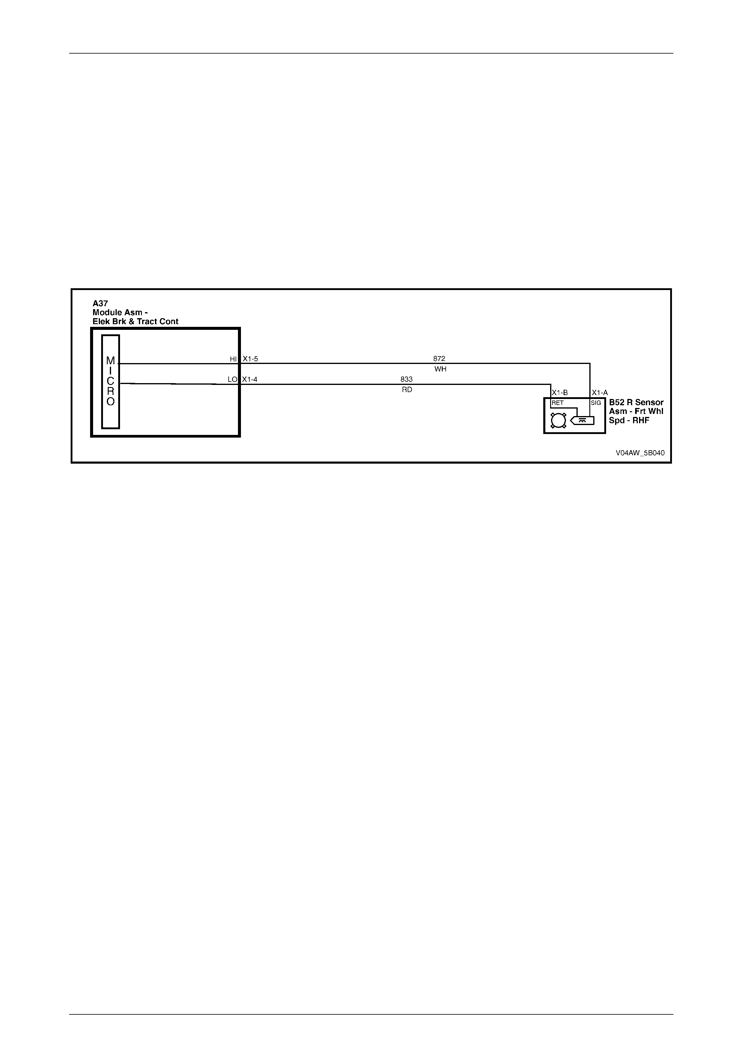
AW D ABS-TCS Page 5B–59
Page 5B–59
7.4 DTC C0041 – Front Right Wheel Speed
Sensor Signal Correlation
Circuit Descri ption
The ECU supplies ground to the front right wheel speed sensor low reference circuit 833.
The wheel speed sensor in conjunction with a pulse ring generates an AC signal voltage. The amplitude and frequency
of the signal generated is proportional to the wheel speed. The ECU monitors the wheel speed sensor signal voltage to
determine the wheel speed of each wheel.
DTC C0041 sets if the ECU detects a plausibility error and/or a short to ground condition in the front right wheel speed
sensor signal circuit 872 and there is a deviation of more than 6 km/h between the front right wheel speed and reference
vehicle speed.
Figure 5B – 43
Diagnostic Aids
Conditions for Running DTC C0041
• The ignition is switched on.
• Vehicle speed is approximately over 40 km/h.
• Brake pedal is not depressed.
• ABS-TCS is not active.
Conditions for Setting DTC C0041
If the front right wheel speed sensor signal circuit 872 is shorted to ground and the ECU detects a deviation of more
than 6 km/h between the front right wheel speed and the reference vehicle speed.
Action Taken when DTC C0041 Sets
• The ECU disables the ABS-TCS for the duration of the ignition cycle.
• The ABS wa rning lam p , the ABS warning icon and the trac-off icon activates.
• The brake failure lamp activates.
Additional information
• Refer to 4.2 DTCs for information on the conditions for clearing DTCs.
• High voltage or high current devices such as spark plugs and spark plug wires may induce electrical noise on the
front right wheel speed sensor circuit. This electrical noise can interfere with normal wheel speed sensor
operation. Ensure that the wheel speed sensor wiring harness is routed away from these high voltage or high
current devices.
• For intermittent fault conditions, refer to 6 Intermittent Conditions.
• Refer to Figure 5B – 44 for the ECU and wheel speed sensor connector illustrations.

AW D ABS-TCS Page 5B–60
Page 5B–60
Figure 5B – 44
Test Description
Step 2 This Step verifies if the fault is currently present.
Step 3 This Step tests the front right wheel speed sensor internal circuitry.
Step 5 This Step tests the front right wheel speed sensor output voltage capacity.

AW D ABS-TCS Page 5B–61
Page 5B–61
DTC C0041 Diagnostic Table
Step Action Value(s) Yes No
1 Was the ABS-TCS Main Diagnostic Table performed? – Go to Step 2 Refer to
5.5 ABS-TCS Ma in
Diagnostic Starting
Point.
2 1 Using Tech 2, observe the Freeze Frame / Failure
Record for this DTC.
2 Switch off the ignition for 10 seconds.
3 Road test the vehicle within the conditions for
running this DTC or within the conditions in the
Freeze Frame/Failure Record.
Did DTC C0041 fail this ignition?
–
Go to Step 3
Refer to DTC C0041
Additional
Information.
3 1 Disconnect the front right wheel speed sensor
connector.
2 Using a digital multimeter, measure the resistance
across the wheel speed sensor connector.
Is the resistance within the specified range? 1.4 - 1.8 kΩ
@ 20°c Go to Step 4 Go to Step 9
4 1 Raise the front of the vehicle and support on
safety stands. Refer to Section 0A General
Information for location of the jacking points.
2 Connect an oscilloscope to the front right wheel
speed sensor connector terminals.
3 Spin the front right wheel.
4 Observe the wheel speed sensor output signal
pattern. Refer to 3.3 Wheel Speed Sensors.
NOTE
If an oscilloscope is not available, perform
the following visual inspection:
• Inspect the front right wheel speed
sensor pulse ring for damaged teeth
• While rotating the front right wheel,
check the wheel speed sensor alignment
to the pulse ring.
• Check the front right wheel speed
sensor run-out.
• Check the front right wheel speed
sensor or pulse ring for dirt or other
contaminants that may affect its
operation.
Was any fault found and rectified?
–
Go to Step 11 Go to Step 5
5 1 Using a digital multimeter, measure the AC signal
voltage across the front right wheel speed sensor
connector while spinning the front right wheel.
Is the voltage more than the specified value?
100 mV
Go to Step 6 Go to Step 9
6 Inspect for poor wiring connection at the front right
wheel speed sensor wiring connector. Refer to Section
12P Wiring Diagrams for information on testing wiring
circuits.
Was any fault found and rectified?
–
Go to Step 11 Go to Step 7

AW D ABS-TCS Page 5B–62
Page 5B–62
Step Action Value(s) Yes No
7 Test the wheel speed sensor signal circuit 872 and low
reference circuit 833 for a high resistance, open circuit,
short to voltage, short to ground or shorted together
condition. Refer to Section 12P Wiring Diagrams for
information on wiring circuit testing and repair.
Was any fault found and rectified?
–
Go to Step 11 Go to Step 8
8 Inspect for poor connections at the ECU wiring
connector. Refer to Section 12P Wiring Diagrams for
information on wiring circuit testing and repair.
Was any fault found and rectified?
–
Go to Step 11 Go to Step 10
9 Replace the front right wheel speed sensor. Refer to
9.4 Front Right Wheel Speed Sensor.
Was the repair completed? – Go to Step 11 –
10 Replace the ECU . Refer to 9.3 ECU /hydraulic
modulator.
Was the repair completed? – Go to Step 11 –
11 1 Using Tech 2, clear the DTCs.
2 Switch off the ignition for 10 seconds.
3 Operate the vehicle within the conditions for
running DTC C0041.
Did DTC C0041 fail this ignition?
–
Go to Step 2 Go to Step 12
12 Using Tech 2, select the DTC display function.
Are there any DTC displayed? – Go to the
appropriate DTC
Table. System OK
When all diagnosis and repairs are completed, check the system for correct operation.
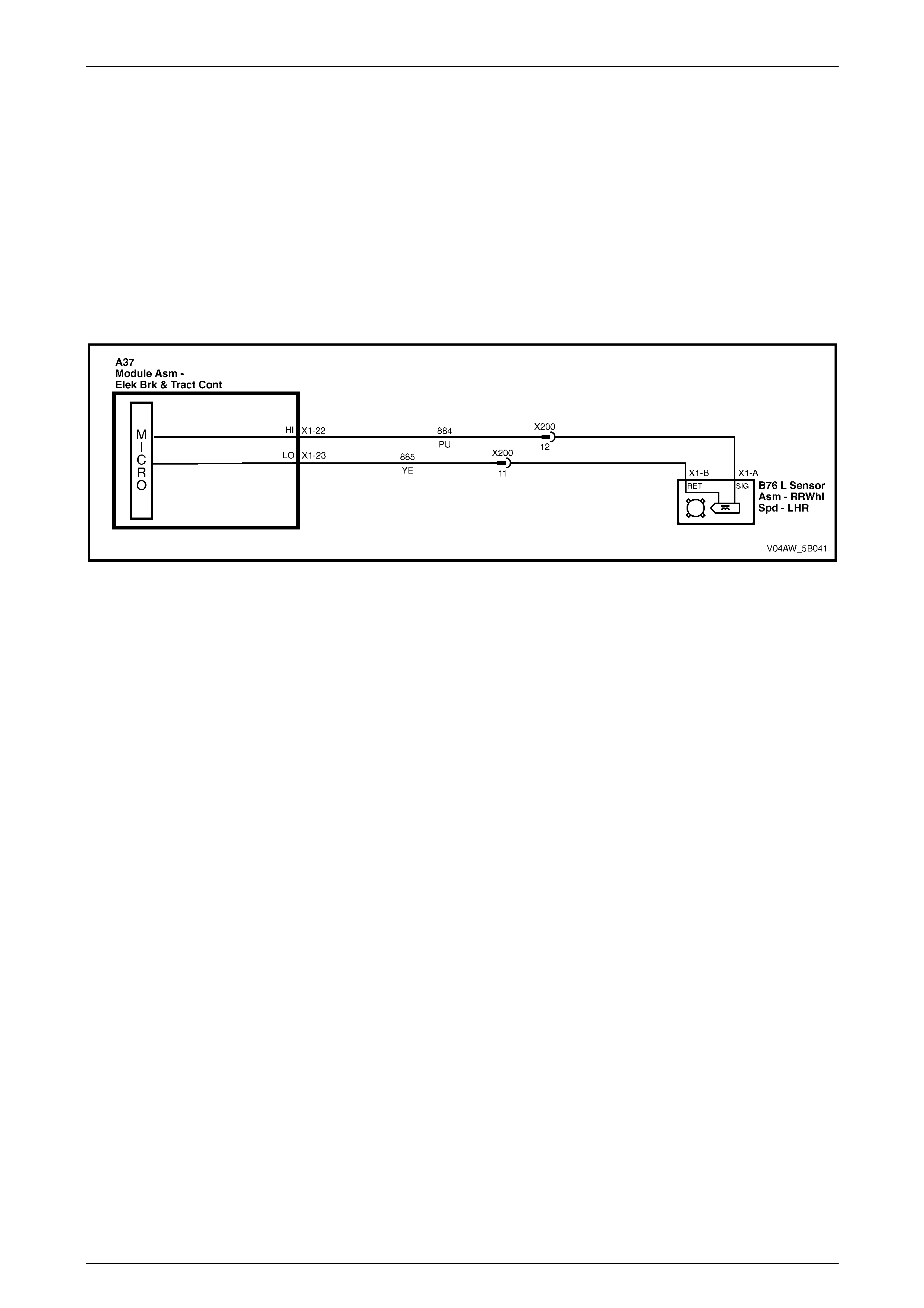
AW D ABS-TCS Page 5B–63
Page 5B–63
7.5 DTC C0045 – Rear Left Wheel Speed
Sensor Short or Open Circuit
Circuit Descri ption
The ECU supplies ground to the rear left wheel speed sensor low reference circuit 885.
The wheel speed sensor in conjunction with a pulse ring generates an AC signal voltage. The amplitude and frequency
of the signal generated is proportional to the wheel speed. The ECU monitors each wheel speed sensor signal voltage
to determine the speed of each wheel.
If the ECU detects a short to voltage or an open circuit condition in the rear left wheel speed sensor signal circuit 884
and/or low reference circuit 885 DTC C0045 sets.
Figure 5B – 45
Diagnostic Aids
Conditions for Running DTC C0045
The ignition is switched on.
Conditions for Setting DTC C0045
If there is a short to voltage or open circuit fault condition in the rear left wheel speed sensor signal circuit 884 or low
reference circuit 885.
Action Taken When DTC C0045 Sets
• The ECU disables the ABS-TCS for the duration of the ignition cycle.
• The ABS wa rning lam p , the ABS warning icon and the trac-off icon activates.
• The brake failure lamp activates.
Additional information
• Refer to 4.2 DTCs for information on the conditions for clearing DTCs.
• High voltage or high current devices such as spark plugs and spark plug wires may induce electrical noise on the
rear left wheel speed sensor circuit. This electrical noise can interfere with normal wheel speed sensor operation.
Ensure that the wheel speed sensor wiring harness is routed away from these high voltage or high current
devices.
• For intermittent fault conditions, refer to 6 Intermittent Conditions.
• Refer to Figure 5B – 46 for the ECU and wheel speed sensor connector illustrations.
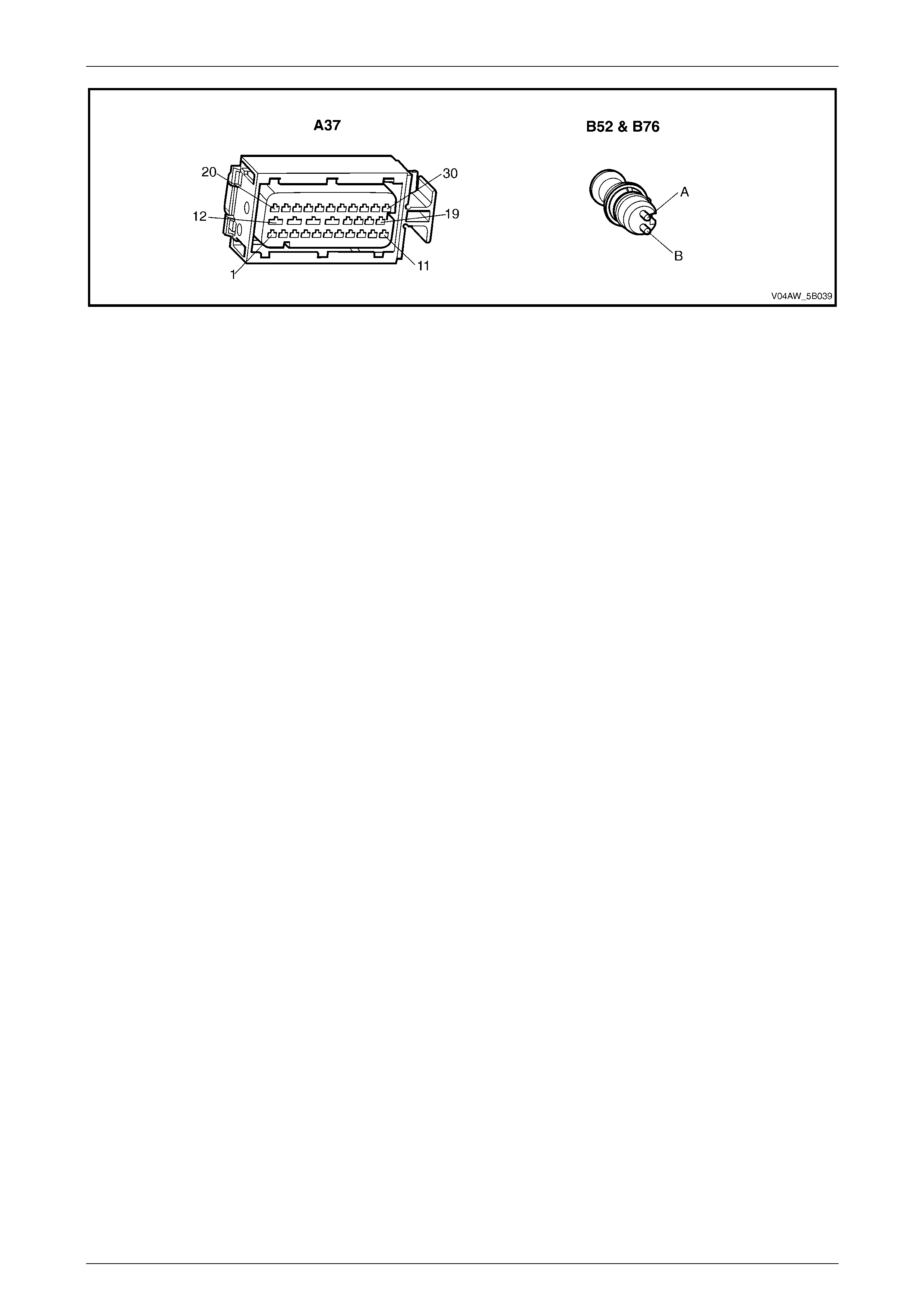
AW D ABS-TCS Page 5B–64
Page 5B–64
Figure 5B – 46
Test Description
Step 2 This Step verifies if the fault is currently present.
Step 3 This Step tests the rear left wheel speed sensor internal circuitry.
Step 5 This Step tests the rear left wheel speed sensor output voltage capacity.

AW D ABS-TCS Page 5B–65
Page 5B–65
DTC C0045 Diagnostic Table
Step Action Value(s) Yes No
1 Was the ABS-TCS Main Diagnostic Table performed? – Go to Step 2 Refer to
5.5 ABS-TCS Ma in
Diagnostic Starting
Point.
2 1 Using Tech 2, observe the Freeze Frame / Failure
Record for this DTC.
2 Switch off the ignition for 10 seconds.
3 Road test the vehicle within the conditions for
running this DTC or within the conditions in the
Freeze Frame/Failure Record.
Did DTC C0045 fail this ignition?
–
Go to Step 3
Refer to DTC C0045
Additional
Information.
3 1 Disconnect the rear left wheel speed sensor
connector.
2 Using a digital multimeter, measure the resistance
across the rear left wheel speed sensor
connector.
Is the resistance within the specified range? 1.4 - 1.8 kΩ
@ 20°c Go to Step 4 Go to Step 9
4 1 Raise the rear of the vehicle and support on
safety stands. Refer to Section 0A General
Information for location of the jacking points.
2 Connect an oscilloscope to the rear left wheel
speed sensor connector terminals.
3 Spin the rear left wheel.
4 Observe the wheel speed sensor output signal
pattern. Refer to 3.3 Wheel Speed Sensors.
NOTE
If an oscilloscope is not available, perform
the following visual inspection:
• Inspect the rear left wheel speed sensor
pulse ring for damaged teeth
• While rotating the rear left wheel, check
the wheel speed sensor alignment to the
pulse ring.
• Check the rear left wheel speed sensor
run-out.
• Check the rear left wheel speed sensor
or pulse ring for dirt or other
contaminants that may affect its
operation.
Was any fault found and rectified?
–
Go to Step 11 Go to Step 5
5 1 Using a digital multimeter, measure the AC signal
voltage across the rear left wheel speed sensor
connector while spinning the rear left wheel.
Is the voltage more than the specified value?
100 mV
Go to Step 6 Go to Step 9
6 Inspect for poor wiring connection at the rear left wheel
speed sensor wiring connector. Refer to Section 12P
Wiring Diagrams for information on testing wiring
circuits.
Was any fault found and rectified?
–
Go to Step 11 Go to Step 7

AW D ABS-TCS Page 5B–66
Page 5B–66
Step Action Value(s) Yes No
7 Test the rear left wheel speed sensor signal circuit 884
and low reference circuit 885 for a high resistance,
open circuit, short to voltage, short to ground or shorted
together condition. Refer to Section 12P Wiring
Diagrams for information on wiring circuit testing and
repair.
Was any fault found and rectified?
–
Go to Step 11 Go to Step 8
8 Inspect for poor connections at the ECU wiring
connector. Refer to Section 12P Wiring Diagrams for
information on wiring circuit testing and repair.
Was any fault found and rectified?
–
Go to Step 11 Go to Step 10
9 Replace the rear left wheel speed sensor. Refer to
9.6 Rear Wheel Speed Sensor.
Was the repair completed? – Go to Step 11 –
10 Replace the ECU . Refer to 9.3 ECU /hydraulic
modulator.
Was the repair completed? – Go to Step 11 –
11 1 Using Tech 2, clear the DTCs.
2 Switch off the ignition for 10 seconds.
3 Operate the vehicle within the conditions for
running DTC C0045.
Did DTC C0045 fail this ignition?
–
Go to Step 2 Go to Step 12
12 Using Tech 2, select the DTC display function.
Are there any DTC displayed? – Go to the
appropriate DTC
Table. System OK
When all diagnosis and repairs are completed, check the system for correct operation.
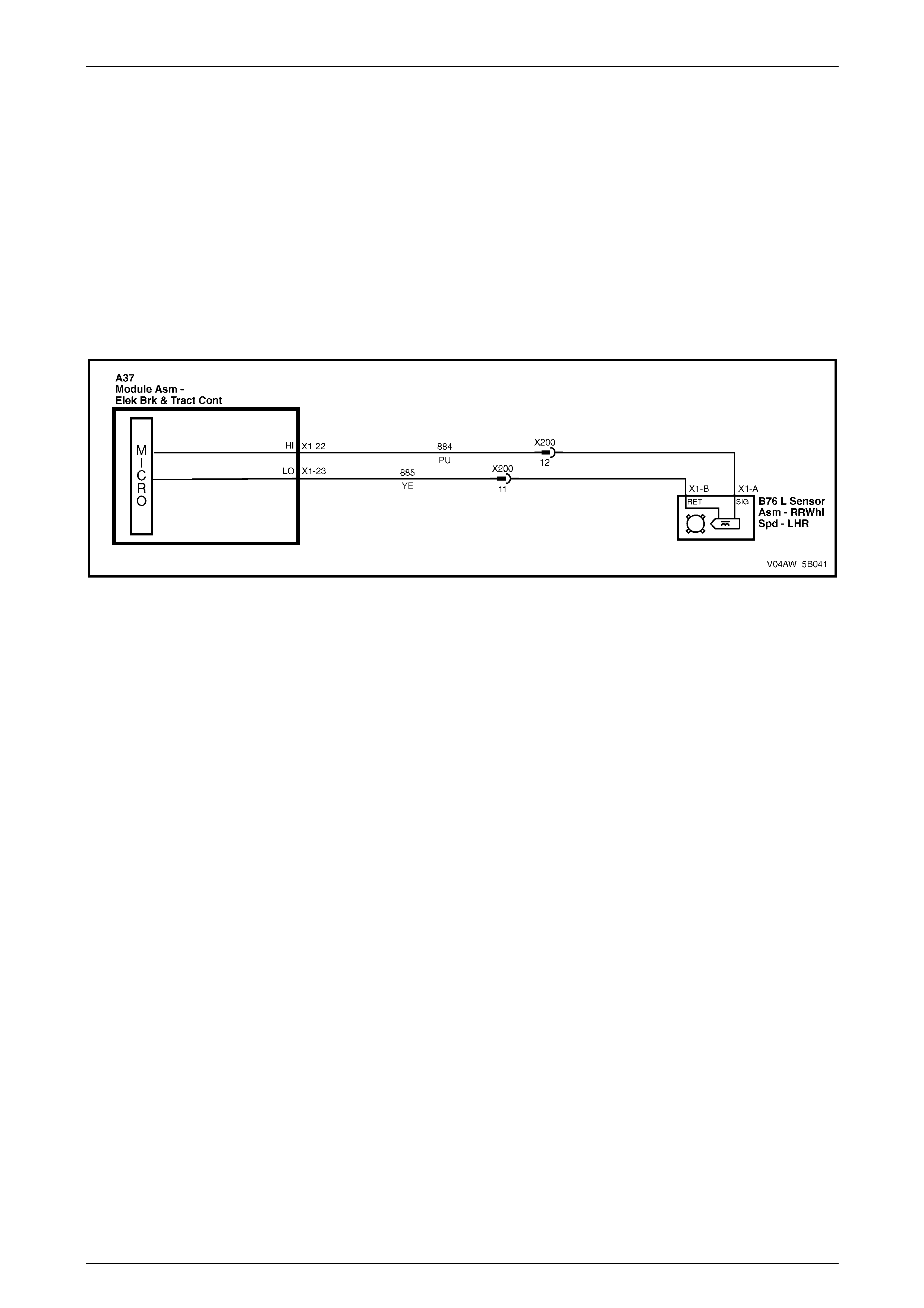
AW D ABS-TCS Page 5B–67
Page 5B–67
7.6 DTC C0046 – Rear Left Wheel Speed
Sensor Signal Correlation
Circuit Descri ption
The ECU supplies ground to the rear left wheel speed sensor low reference circuit 885.
The wheel speed sensor in conjunction with a pulse ring generates an AC signal voltage. The amplitude and frequency
of the signal generated is proportional to the wheel speed. The ECU monitors the wheel speed sensor signal voltage to
determine the wheel speed of each wheel.
DTC C0046 sets if the ECU detects a plausibility error and/or a short to ground condition in the rear left wheel speed
sensor signal circuit 884 and there is a deviation of more than 6 km/h between the rear left wheel speed and reference
vehicle speed.
Figure 5B – 47
Diagnostic Aids
Conditions for Running DTC C0046
• The ignition is switched on.
• Vehicle speed is approximately over 40 km/h.
• Brake pedal is not depressed.
• ABS-TCS is not active.
Conditions for Setting DTC C0046
If the rear left wheel speed sensor signal circuit 884 is shorted to ground and the ECU detects a deviation of more than
6 km/h between the rear left wheel speed and the reference vehicle speed.
Action Taken When DTC C0046 Sets
• The ECU disables the ABS-TCS for the duration of the ignition cycle.
• The ABS wa rning lam p , the ABS warning icon and the trac-off icon activates.
• The brake failure lamp activates.
Additional information
• Refer to 4.2 DTCs for information on the conditions for clearing DTCs.
• High voltage or high current devices such as spark plugs and spark plug wires may induce electrical noise on the
rear left wheel speed sensor circuit. This electrical noise can interfere with normal wheel speed sensor operation.
Ensure that the wheel speed sensor wiring harness is routed away from these high voltage or high current
devices.
• For intermittent fault conditions, refer to 6 Intermittent Conditions.
• Refer to Figure 5B – 48 for the ECU and wheel speed sensor connector illustrations.

AW D ABS-TCS Page 5B–68
Page 5B–68
Figure 5B – 48
Test Description
Step 2 This Step verifies if the fault is currently present.
Step 3 This Step tests the rear left wheel speed sensor internal circuitry.
Step 5 This Step tests the rear left wheel speed sensor output voltage capacity.

AW D ABS-TCS Page 5B–69
Page 5B–69
DTC C0046 Diagnostic Table
Step Action Value(s) Yes No
1 Was the ABS-TCS Main Diagnostic Table performed? – Go to Step 2 Refer to
5.5 ABS-TCS Ma in
Diagnostic Starting
Point.
2 1 Using Tech 2, observe the Freeze Frame / Failure
Record for this DTC
2 Switch off the ignition for 10 seconds.
3 Road test the vehicle within the conditions for
running this DTC or within the conditions in the
Freeze Frame/Failure Record.
Did DTC C0046 fail this ignition?
–
Go to Step 3
Refer to DTC C0046
Additional
Information.
3 1 Disconnect the rear left wheel speed sensor
connector.
2 Using a digital multimeter, measure the resistance
across the wheel speed sensor connector.
Is the resistance within the specified range? 1.4 - 1.8 kΩ
@ 20°c Go to Step 4 Go to Step 9
4 1 Raise the rear of the vehicle and support on
safety stands, Refer to Section 0A General
Information for location of the jacking points.
2 Connect an oscilloscope to the rear left wheel
speed sensor connector terminals.
3 Spin the rear left wheel.
4 Observe the wheel speed sensor output signal
pattern. Refer to 3.3 Wheel Speed Sensors.
NOTE
If an oscilloscope is not available, perform
the following visual inspection:
• Inspect the rear left wheel speed sensor
pulse ring for damaged teeth
• While rotating the rear left wheel, check
the wheel speed sensor alignment to the
pulse ring.
• Check the rear left wheel speed sensor
run-out.
• Check the rear left wheel speed sensor
or pulse ring for dirt or other
contaminants that may affect its
operation.
Was any fault found and rectified?
–
Go to Step 11 Go to Step 5
5 1 Using a digital multimeter, measure the AC signal
voltage across the rear left wheel speed sensor
connector while spinning the rear left wheel.
Is the voltage more than the specified value?
100 mV
Go to Step 6 Go to Step 9
6 Inspect for poor wiring connection at the rear left wheel
speed sensor wiring connector. Refer to Section 12P
Wiring Diagrams for information on testing wiring
circuits.
Was any fault found and rectified?
–
Go to Step 11 Go to Step 7

AW D ABS-TCS Page 5B–70
Page 5B–70
Step Action Value(s) Yes No
7 Test the wheel speed sensor signal circuit 884 and low
reference circuit 885 for a high resistance, open circuit,
short to voltage, short to ground or shorted together
condition. Refer to Section 12P Wiring Diagrams for
information on wiring circuit testing and repair.
Was any fault found and rectified?
–
Go to Step 11 Go to Step 8
8 Inspect for poor connections at the ECU wiring
connector. Refer to Section 12P Wiring Diagrams for
information on wiring circuit testing and repair.
Was any fault found and rectified?
–
Go to Step 11 Go to Step 10
9 Replace the rear left wheel speed sensor. Refer to
9.6 Rear Wheel Speed Sensor.
Was the repair completed? – Go to Step 11 –
10 Replace the ECU . Refer to 9.3 ECU /hydraulic
modulator.
Was the repair completed? – Go to Step 11 –
11 1 Using Tech 2, clear the DTCs.
2 Switch off the ignition for 10 seconds.
3 Operate the vehicle within the conditions for
running DTC C0046.
Did DTC C0046 fail this ignition?
–
Go to Step 2 Go to Step 12
12 Using Tech 2, select the DTC display function.
Are there any DTC displayed? – Go to the
appropriate DTC
Table. System OK
When all diagnosis and repairs are completed, check the system for correct operation.
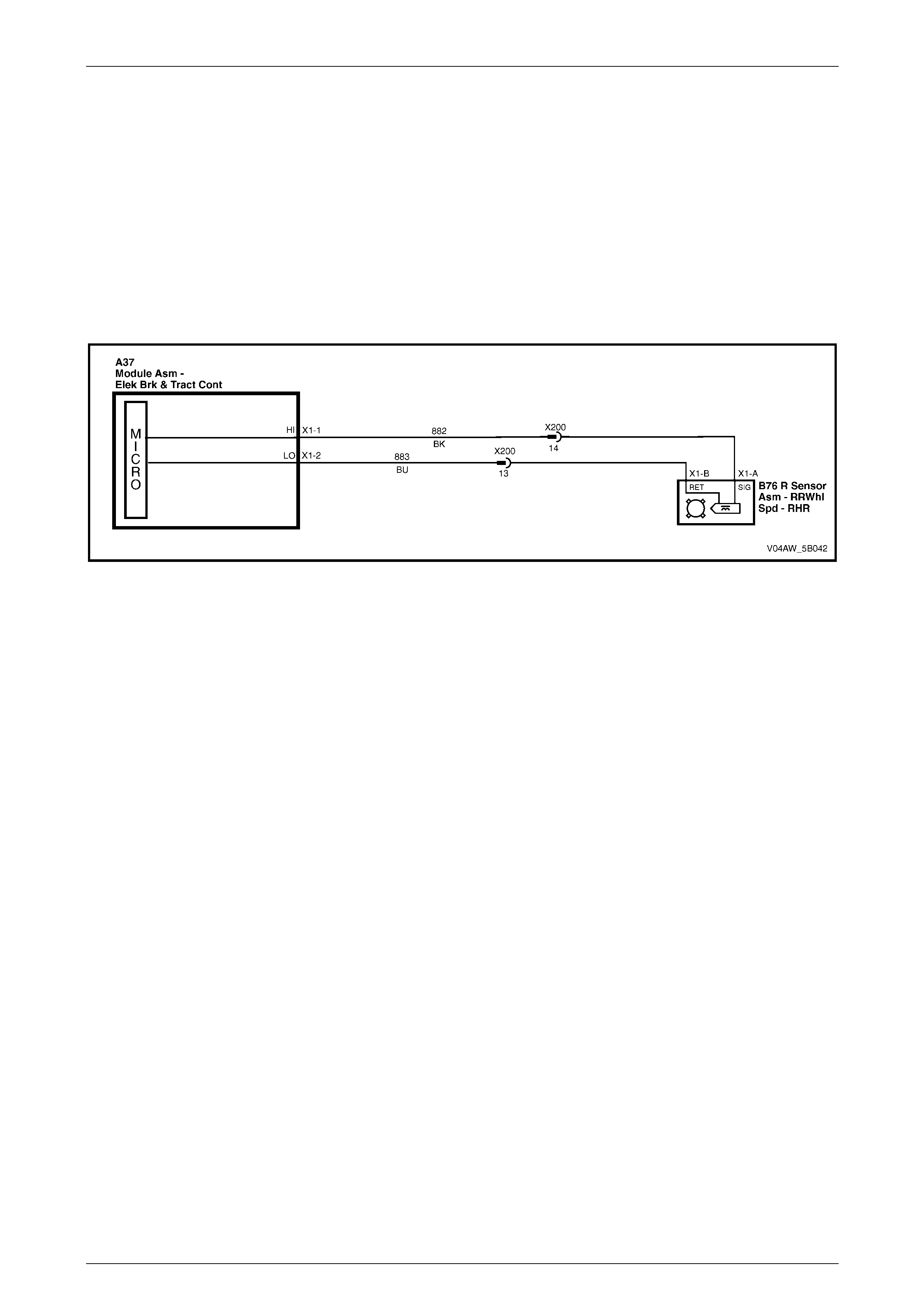
AW D ABS-TCS Page 5B–71
Page 5B–71
7.7 DTC C0050 – Rear Right Wheel Speed
Sensor Short or Open Circuit
Circuit Descri ption
The ECU supplies ground to the rear right wheel speed sensor low reference circuit 883.
The wheel speed sensor in conjunction with a pulse ring generates an AC signal voltage. The amplitude and frequency
of the signal generated is proportional to the wheel speed. The ECU monitors each wheel speed sensor signal voltage
to determine the speed of each wheel.
DTC C0050 sets if the ECU detects a short to voltage or an open circuit condition in the rear right wheel speed sensor
signal circuit 882 and/or low reference circuit 883.
Figure 5B – 49
Diagnostic Aids
Conditions for Running DTC C0050
The ignition is switched on.
Conditions for Setting DTC C0050
If there is a short to voltage or open circuit fault condition in the rear right wheel speed sensor signal circuit 882 or low
reference circuit 883.
Action Taken when DTC C0050 Sets
• The ECU disables the ABS-TCS for the duration of the ignition cycle.
• The ABS wa rning lam p , the ABS warning icon and the trac-off icon activates.
• The brake failure lamp activates.
Additional information
• Refer to 4.2 DTCs for information on the conditions for clearing DTCs.
• High voltage or high current devices such as spark plugs and spark plug wires may induce electrical noise on the
wheel speed sensor circuit. This electrical noise can interfere with normal wheel speed sensor operation. Ensure
that the rear right wheel speed sensor wiring harness is routed away from these high voltage or high current
devices.
• For intermittent fault conditions, refer to 6 Intermittent Conditions.
• Refer to Figure 5B – 50 for the ECU and wheel speed sensor connector illustrations.

AW D ABS-TCS Page 5B–72
Page 5B–72
Figure 5B – 50
Test Description
Step 2 This Step verifies if the fault is currently present.
Step 3 This Step tests the rear right wheel speed sensor internal circuitry.
Step 5 This Step tests the rear right wheel speed sensor output voltage capacity.

AW D ABS-TCS Page 5B–73
Page 5B–73
DTC C0050 Diagnostic Table
Step Action Value(s) Yes No
1 Was the ABS-TCS Main Diagnostic Table performed? – Go to Step 2 Refer to
5.5 ABS-TCS Ma in
Diagnostic Starting
Point.
2 1 Using Tech 2, observe the Freeze Frame / Failure
Record for this DTC.
2 Switch off the ignition for 10 seconds.
3 Road test the vehicle within the conditions for
running this DTC or within the conditions in the
Freeze Frame/Failure Record.
Did DTC C0050 fail this ignition?
–
Go to Step 3
Refer to DTC C0050
Additional
Information.
3 1 Disconnect the rear right wheel speed sensor
connector.
2 Using a digital multimeter, measure the resistance
across the wheel speed sensor connector.
Is the resistance within the specified range? 1.4 - 1.8 kΩ
@ 20°c Go to Step 4 Go to Step 9
4 1 Raise the rear of the vehicle and support on
safety stands. Refer to Section 0A General
Information for location of the jacking points.
2 Connect an oscilloscope to the rear right wheel
speed sensor connector terminals.
3 Spin the rear right wheel.
4 Observe the wheel speed sensor output signal
pattern. Refer to 3.3 Wheel Speed Sensors.
NOTE
If an oscilloscope is not available, perform
the following visual inspection:
• Inspect the rear right wheel speed
sensor pulse ring for damaged teeth.
• While rotating the rear right wheel,
check the wheel speed sensor alignment
to the pulse ring.
• Check the rear right wheel speed sensor
run-out.
• Check the rear right wheel speed sensor
or pulse ring for dirt or other
contaminants that may affect its
operation.
Was any fault found and rectified?
–
Go to Step 11 Go to Step 5
5 1 Using a digital multimeter, measure the AC signal
voltage across the rear right wheel speed sensor
connector while spinning the rear right wheel.
Is the voltage more than the specified value?
100 mV
Go to Step 6 Go to Step 9
6 Inspect for poor wiring connection at the rear right
wheel speed sensor wiring connector. Refer to Section
12P Wiring Diagrams for information on testing wiring
circuits.
Was any fault found and rectified?
–
Go to Step 11 Go to Step 7

AW D ABS-TCS Page 5B–74
Page 5B–74
Step Action Value(s) Yes No
7 Test the rear right wheel speed sensor signal circuit
882 and low reference circuit 883 for a high resistance,
open circuit, short to voltage, short to ground or shorted
together condition. Refer to Section 12P Wiring
Diagrams for information on wiring circuit testing and
repair.
Was any fault found and rectified?
–
Go to Step 11 Go to Step 8
8 Inspect for poor connections at the ECU wiring
connector. Refer to Section 12P Wiring Diagrams for
information on wiring circuit testing and repair.
Was any fault found and rectified?
–
Go to Step 11 Go to Step 10
9 Replace the rear right wheel speed sensor. Refer to
9.6 Rear Wheel Speed Sensor.
Was the repair completed? – Go to Step 11 –
10 Replace the ECU . Refer to 9.3 ECU /hydraulic
modulator.
Was the repair completed? – Go to Step 11 –
11 1 Using Tech 2, clear the DTCs.
2 Switch off the ignition for 10 seconds.
3 Operate the vehicle within the conditions for
running DTC C0050.
Did DTC C0050 fail this ignition?
–
Go to Step 2 Go to Step 12
12 Using Tech 2, select the DTC display function.
Are there any DTC displayed? – Go to the
appropriate DTC
Table. System OK
When all diagnosis and repairs are completed, check the system for correct operation.

AW D ABS-TCS Page 5B–75
Page 5B–75
7.8 DTC C0051 – Rear Right Wheel Speed
Sensor Signal Correlation
Circuit Descri ption
The ECU supplies ground to the rear right wheel speed sensor low reference circuit 883.
The wheel speed sensor in conjunction with a pulse ring generates an AC signal voltage. The amplitude and frequency
of the signal generated is proportional to the wheel speed. The ECU monitors the wheel speed sensor signal voltage to
determine the wheel speed of each wheel.
DTC C0051 sets if the ECU detects a plausibility error and/or a short to ground condition in the rear right wheel speed
sensor signal circuit 830 and there is a deviation of more than 6 km/h between the front left wheel speed and vehicle
speed.
Figure 5B – 51
Diagnostic Aids
Conditions for Running DTC C0051
• The ignition is switched on.
• Vehicle speed is over 40 km/h.
• Brake pedal is not depressed.
• ABS-TCS is not active.
Conditions for Setting DTC C0051
If the rear right wheel speed sensor signal circuit is shorted to ground and the ECU detects a deviation of more than 6
km/h between the front left wheel speed and the reference vehicle speed.
Action Taken when DTC C0051 Sets
• The ECU disables the ABS-TCS for the duration of the ignition cycle.
• The ABS wa rning lam p , the ABS warning icon and the trac-off icon activates.
• The brake failure lamp activates.
Additional information
• Refer to 4.2 DTCs for information on the conditions for clearing DTCs.
• High voltage or high current devices such as spark plugs and spark plug wires may induce electrical noise on the
rear right wheel speed sensor circuit. This electrical noise can interfere with normal wheel speed sensor operation.
Ensure that the wheel speed sensor wiring harness is routed away from these high voltage or high current
devices.
• For intermittent fault conditions, refer to 6 Intermittent Conditions.
• Refer to Figure 5B – 52 for the ECU and wheel speed sensor connector illustrations.

AW D ABS-TCS Page 5B–76
Page 5B–76
Figure 5B – 52
Test Description
Step 2 This Step verifies if the fault is currently present.
Step 3 This Step tests the rear right wheel speed sensor internal circuitry.
Step 5 This Step tests the rear right wheel speed sensor output voltage capacity.

AW D ABS-TCS Page 5B–77
Page 5B–77
DTC C0051 Diagnostic Table
Step Action Value(s) Yes No
1 Was the ABS-TCS Main Diagnostic Table performed? – Go to Step 2 Refer to
5.5 ABS-TCS Ma in
Diagnostic Starting
Point.
2 1 Using Tech 2, observe the Freeze Frame / Failure
Record for this DTC.
2 Switch off the ignition for 10 seconds.
3 Road test the vehicle within the conditions for
running this DTC or within the conditions in the
Freeze Frame/Failure Record.
Did DTC C0051 fail this ignition?
–
Go to Step 3
Refer to DTC C0051
Additional
Information.
3 1 Disconnect the rear right wheel speed sensor
connector.
2 Using a digital multimeter, measure the resistance
across the wheel speed sensor connector.
Is the resistance within the specified range? 1.4 - 1.8 kΩ
@ 20°c Go to Step 4 Go to Step 9
4 1 Raise the rear of the vehicle and support on
safety stands. Refer to Section 0A General
Information for location of the jacking points.
2 Connect an oscilloscope to the rear right wheel
speed sensor connector terminals.
3 Spin the rear right wheel.
4 Observe the wheel speed sensor output signal
pattern. Refer to 3.3 Wheel Speed Sensors.
NOTE
If an oscilloscope is not available, perform
the following visual inspection:
• Inspect the rear right wheel speed
sensor pulse ring for damaged teeth.
• While rotating the rear right wheel,
check the wheel speed sensor alignment
to the pulse ring.
• Check the rear right wheel speed sensor
run-out.
• Check the rear right wheel speed sensor
or pulse ring for dirt or other
contaminants that may affect its
operation.
Was any fault found and rectified?
–
Go to Step 11 Go to Step 5
5 1 Using a digital multimeter, measure the AC signal
voltage across the rear right wheel speed sensor
connector while spinning the rear right wheel.
Is the voltage more than the specified value?
100 mV
Go to Step 6 Go to Step 9
6 Inspect for poor wiring connection at the rear right
wheel speed sensor wiring connector. Refer to Section
12P Wiring Diagrams for information on testing wiring
circuits.
Was any fault found and rectified?
–
Go to Step 11 Go to Step 7

AW D ABS-TCS Page 5B–78
Page 5B–78
Step Action Value(s) Yes No
7 Test the wheel speed sensor signal circuit 882 and low
reference circuit 883 for a high resistance, open circuit,
short to voltage, short to ground or shorted together
condition. Refer to Section 12P Wiring Diagrams for
information on wiring circuit testing and repair.
Was any fault found and rectified?
–
Go to Step 11 Go to Step 8
8 Inspect for poor connections at the ECU wiring
connector. Refer to Section 12P Wiring Diagrams for
information on wiring circuit testing and repair.
Was any fault found and rectified?
–
Go to Step 11 Go to Step 10
9 Replace the rear right wheel speed sensor. Refer to
9.6 Rear Wheel Speed Sensor.
Was the repair completed? – Go to Step 11 –
10 Replace the ECU . Refer to 9.3 ECU /hydraulic
modulator.
Was the repair completed? – Go to Step 11 –
11 1 Using Tech 2, clear the DTCs.
2 Switch off the ignition for 10 seconds.
3 Operate the vehicle within the conditions for
running DTC C0051.
Did DTC C0051 fail this ignition?
–
Go to Step 2 Go to Step 12
12 Using Tech 2, select the DTC display function.
Are there any DTC displayed? – Go to the
appropriate DTC
Table. System OK
When all diagnosis and repairs are completed, check the system for correct operation.
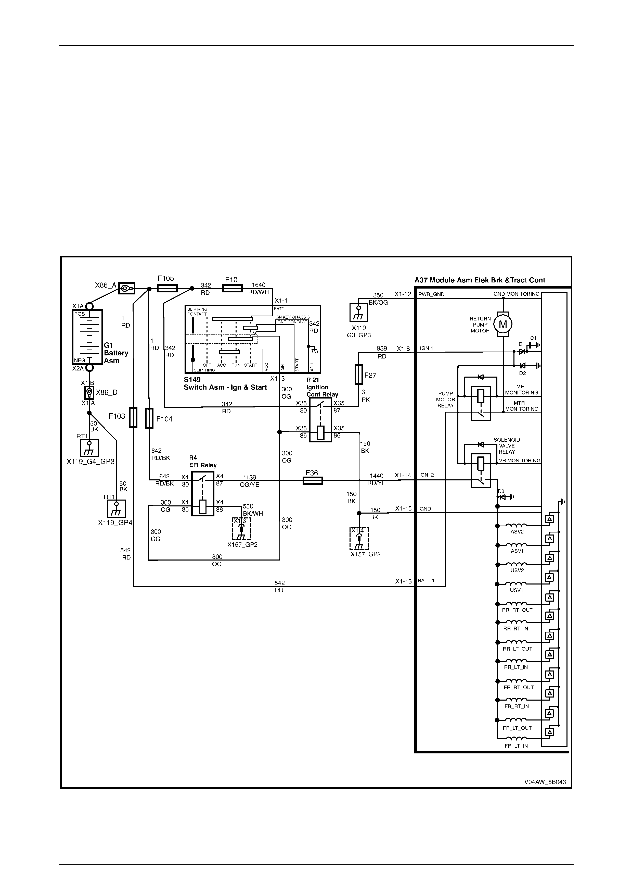
AW D ABS-TCS Page 5B–79
Page 5B–79
7.9 DTC C0110 – Pump Motor or Relay Fault
Circuit Descri ption
The ECU operates the hydraulic modulator pump motor by grounding the pump motor relay control circuit to achieve the
following:
• ABS Reducing Pressure Phase – the hydraulic modulator pump builds-up the brake fluid pressure to allow the
released brake fluid pressure from the slipping wheel to be returned to the brake master cylinder reservoir against
brake pedal pressure.
• TCS Brake Intervention Mode – the hydraulic modulator pump builds-up the brake fluid pressure, which is directed
to the spinning wheel to prevent wheel-spin.
The ECU monitors the pump motor relay and the pump motor circuit for correct operation. DTC C0110 sets if ECU
detects a fault in the relay or in its System Voltage application within a predetermined period.
Figure 5B – 53
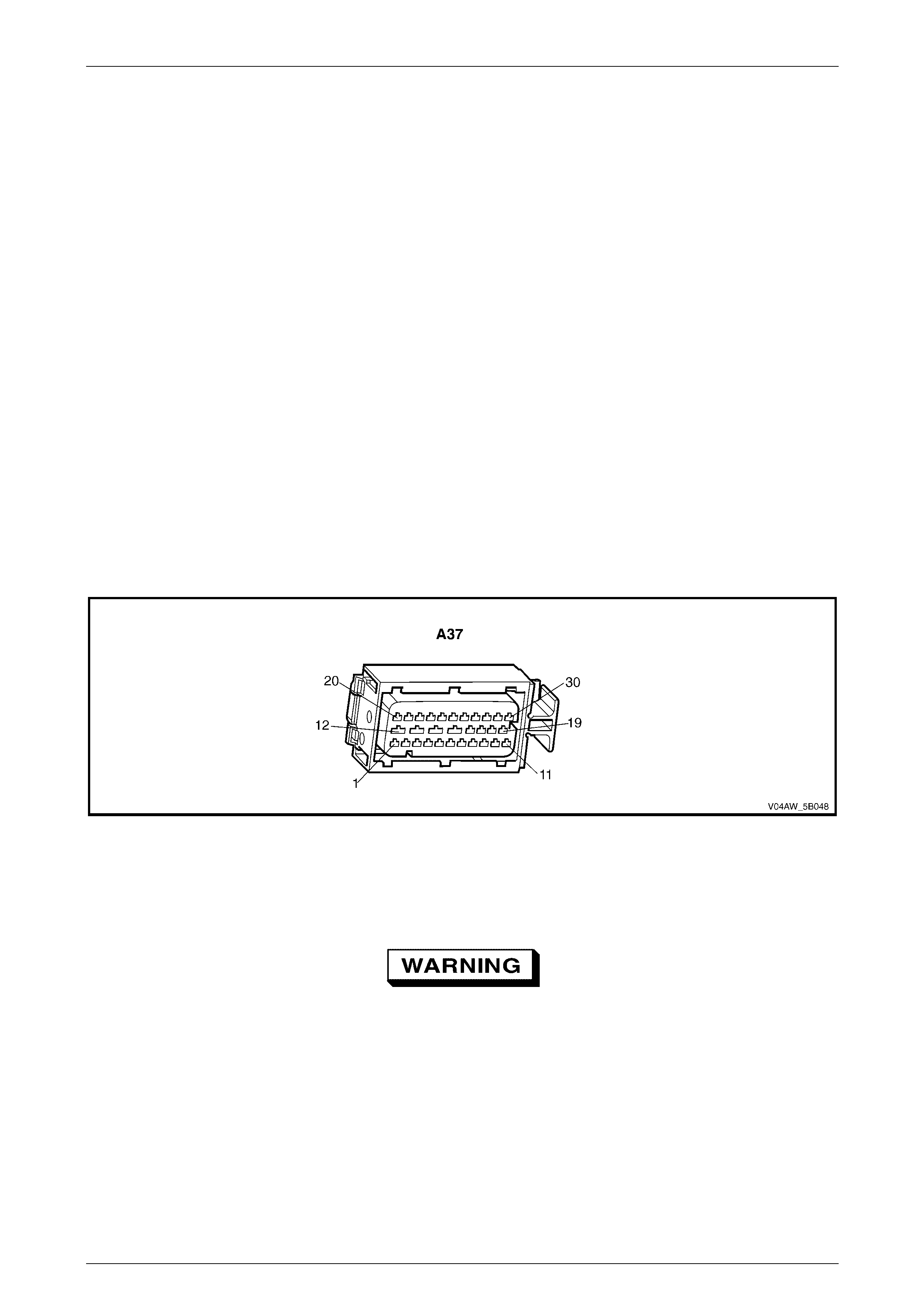
AW D ABS-TCS Page 5B–80
Page 5B–80
Diagnostic Aids
Conditions for Running DTC C0110
• The ignition is switched on.
• The ECU Self-test Initialisation Sequence is complete.
Conditions for Setting DTC C0110
• If the pump motor relay is activated and there is no pump motor system voltage present after 60 milliseconds.
• If the pump motor system voltage is present for more than 2.5 seconds and the pump motor relay did not activate.
• If there is no pump motor run down voltage after the pump motor relay is deactivated.
Action Taken when DTC C0110 Sets
• The ECU disables the ABS-TCS for the duration of the ignition cycle.
• The ABS wa rning lam p , the ABS warning icon and the trac-off icon activates.
• The brake failure lamp activates.
Additional information
• Refer to 4.2 DTCs for information on the conditions for clearing DTCs.
• For intermittent fault conditions, refer to 6 Intermittent Conditions.
• Refer to Figure 5B – 54 for ECU connector illustration.
Figure 5B – 54
Test Description
Step 5 Tests the hydraulic modulator pump motor circuitry for a short to the hydraulic modulator housing.
The hydraulic modulator pump motor wiring
harness must not be repaired. If this wiring
harness is damaged, the hydraulic modulator
assembly must be replaced.

AW D ABS-TCS Page 5B–81
Page 5B–81
DTC C0110 Diagnostic Table
Step Action Value(s) Yes No
1 Was the ABS-TCS Main Diagnostic Table performed? – Go to Step 2 Refer to
5.5 ABS-TCS Ma in
Diagnostic Starting
Point.
2 Using Tech 2, perform the hydraulic modulator pump
motor test.
Did the pump motor pass the test? – Go to Step 3 Go to Step 4
3 1 Switch off the ignition for 10 seconds.
2 Operate the vehicle within the conditions for
running DTC C0110.
3 Using Tech 2, select the DTC display function.
Did DTC C0110 fail this ignition?
–
Go to Step 4
Refer to DTC C0110
Additional
Information.
4 1 Test all ground circuits of the ECU for a high
resistance or an open circuit condition.
2 Test the ABS fuses. Refer to 3.7 ABS fuse
locations.
3 Test the ECU battery supply voltage for a high
resistance, open circuit or short to ground
condition.
Was any fault found and rectified?
–
Go to Step 10 Go to Step 5
5 1 Disconnect the pump motor wiring connector.
2 Using a digital multimeter, measure the resistance
between each of the pump motor connector wiring
circuits and the hydraulic modulator housing.
Is the resistance less than the specified value?
5 Ω
Go to Step 6 Go to Step 7
6 Inspect for poor wiring connection at pump motor wiring
connections at the hydraulic modulator. Refer to
Section 12P Wiring Diagrams for information on testing
wiring circuits.
Was any fault found and rectified?
–
Go to Step 10 Go to Step 8
7 Inspect for poor connections at the ECU wiring
connector. Refer to Section 12P Wiring Diagrams for
information on testing wiring circuits.
Was any fault found and rectified?
–
Go to Step 10 Go to Step 9
8 Replace the hydraulic modulator. Refer to 9.3 ECU
/hydraulic modulator .
Was the repair completed? – Go to Step 10 –
9 Replace the ECU . Refer to 9.3 ECU /hydraulic
modulator.
Was the repair completed? – Go to Step 10 –
10 1 Using Tech 2, clear the DTCs.
2 Switch off the ignition for 10 seconds.
3 Operate the vehicle within the conditions for
running DTC C0110.
Did DTC C0110 fail this ignition?
–
Go to Step 2 Go to Step 11
11 Using Tech 2, select the DTC display function.
Are there any DTC displayed? – Go to the
appropriate DTC
Table. System OK
When all diagnosis and repairs are completed, check the system for correct operation.
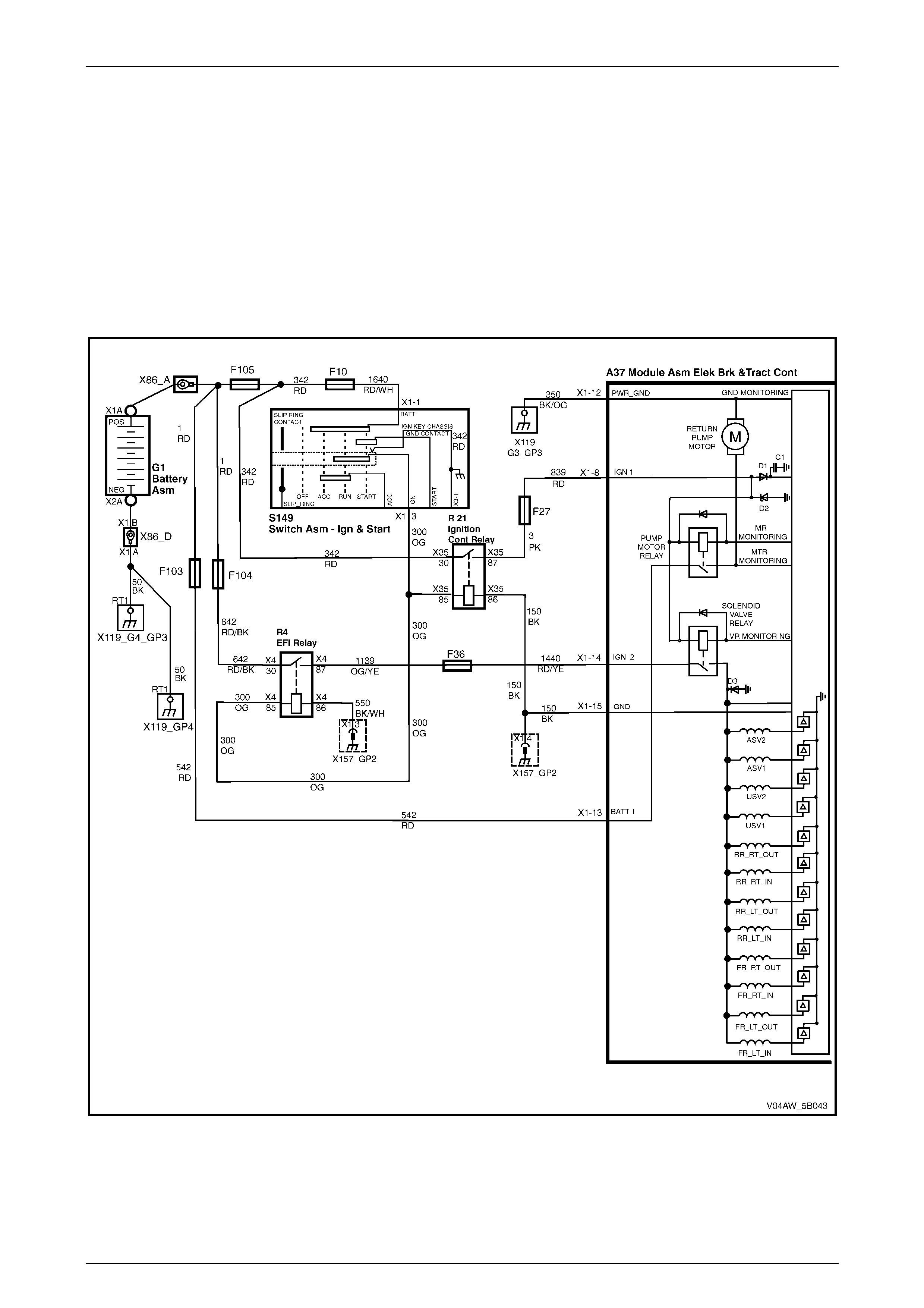
AW D ABS-TCS Page 5B–82
Page 5B–82
7.10 DTC C0121 – Valve Solenoid Relay Fault
Circuit Descri ption
Ignition Circuit 839 supplies battery voltage to the ECU to energise the ECU solenoid valve relay when the ignition is
switched on. When energised, the solenoid valve relay supplies System Voltage to the hydraulic modulator solenoid
valve coils. The solenoid valve relay remains energised until the ignition is switched off or the ABS-TCS is disabled.
The ECU controls the operation of each solenoid valve by applying ground to the solenoid valve coil control circuit to
modulate the brake fluid pressure of each brake circuit.
The ECU monitors the solenoid valve system voltage circuit for correct operation. DTC C0121 sets if ECU detects a fault
in the relay or in its system voltage circuit application within a predetermined period.
Figure 5B – 55
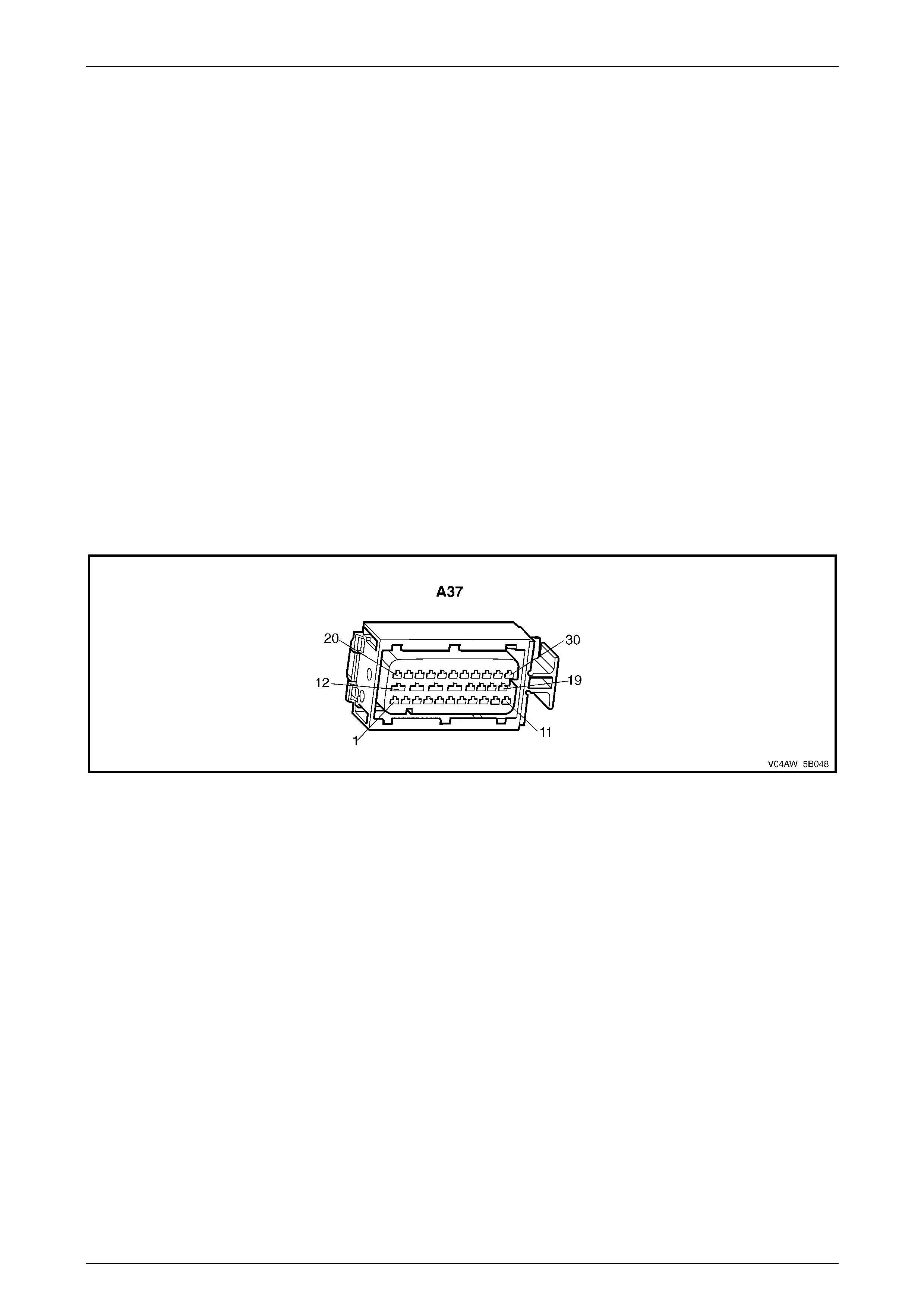
AW D ABS-TCS Page 5B–83
Page 5B–83
Diagnostic Aids
Conditions for Running DTC C0121
• The ignition is switched on.
Conditions for Setting DTC C0121
• If the solenoid valve relay is commanded on and the ECU did not detect the system voltage at the solenoid valve
coils.
• If the ECU commands the solenoid valve relay off and battery voltage is still present at the solenoid valve coils.
Action Taken when DTC C0121 Sets
• The ECU disables the ABS-TCS for the duration of the ignition cycle.
• The ABS wa rning lam p , the ABS warning icon and the trac-off icon activates.
• The brake failure lamp may activate.
Additional information
• Refer to 4.2 DTCs for information on the conditions for clearing DTCs.
• For intermittent fault conditions, refer to 6 Intermittent Conditions.
• Refer to Figure 5B – 56 for ECU connector illustration.
Figure 5B – 56
Test Description
Step 2 This step verifies operation of the hydraulic modulator solenoid valves.

AW D ABS-TCS Page 5B–84
Page 5B–84
DTC C0121 Diagnostic Table
Step Action Value(s) Yes No
1 Was the ABS-TCS Main Diagnostic Table performed? – Go to Step 2 Refer to
5.5 ABS-TCS Ma in
Diagnostic Starting
Point.
2 Using Tech 2, perform the hydraulic modulator solenoid
valve test.
Did the solenoid valves pass the test? – Go to Step 3 Go to Step 4
3 1 Switch off the ignition for 10 seconds.
2 Operate the vehicle within the conditions for
setting DTC C0121.
3 Using Tech 2,select the DTC display function.
Did DTC C0121 fail this ignition?
–
Go to Step 4
Refer to DTC C0121
Additional
Information.
4 1 Test all ground circuits of the ECU for a high
resistance or an open circuit condition.
2 Test the ABS fuses. Refer to 3.7 ABS fuse
locations.
3 Test the ECU battery supply voltage for a high
resistance, open circuit or short to ground
condition.
Was any fault found and rectified?
–
Go to Step 6 Go to Step 5
5 Replace the ECU . Refer to 9.3 ECU /hydraulic
modulator.
Was the repair completed? – Go to Step 6 –
6 1 Using Tech 2, clear the DTCs.
2 Switch off the ignition for 10 seconds.
3 Operate the vehicle within the conditions for
setting DTC C0121.
Did DTC C0121 fail this ignition?
–
Go to Step 2 Go to Step 7
7 Using Tech 2, select the DTC display function.
Are there any DTC displayed? – Go to the
appropriate DTC
Table. System OK
When all diagnosis and repairs are completed, check the system for correct operation.
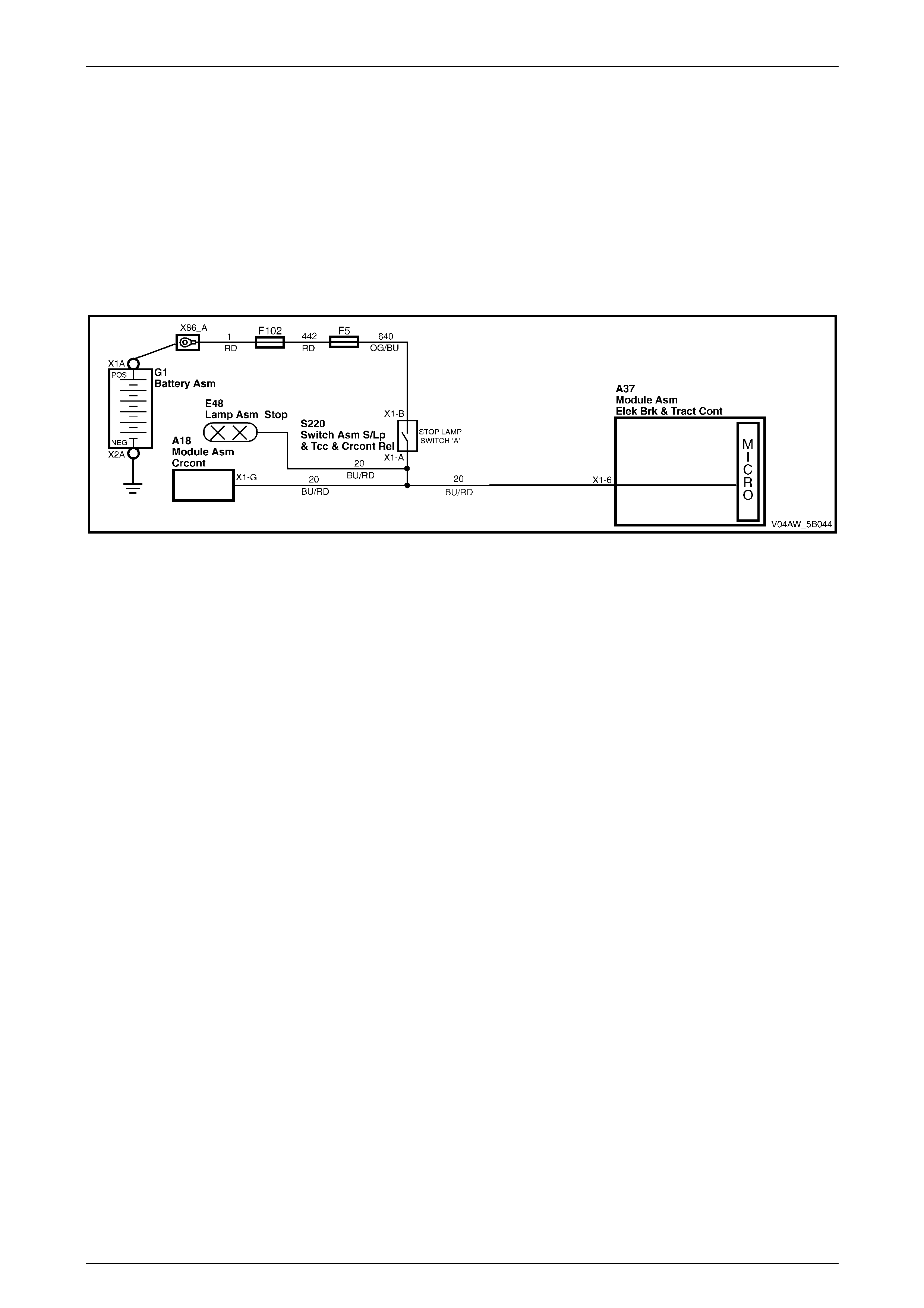
AW D ABS-TCS Page 5B–85
Page 5B–85
7.11 DTC C0161 – Brake Switch Circuit
Malfunction
Circuit Descri ption
Circuit 640 supplies battery voltage to the stop lamp switch. The stop lamp switch is a normally open switch that closes
when the brake pedal is depressed. When the brake pedal is depressed, the stop lamp switch supplies signal voltage to
the stop lamp signal circuit 20.
The ECU monitors the brake switch signal voltage to check stop lamp continuity and to determine when the brake is
applied. DTC C0161 sets if the ECU detects a fault in the brake switch signal circuit 20 or both stop lamps are faulty.
Figure 5B – 57
Diagnostic Aids
Conditions for Running DTC C0161
• The ignition is switched on.
Conditions for Setting DTC C0161
• The ECU detects an open condition in the brake switch signal circuit.
• Both stop lamps are faulty.
• The stop lamp switch input voltage is between 7.0 – 11 volts.
• An open or high resistance condition in the following circuit:
• Stop lamp switch signal voltage circuit.
• Stop lamp ground circuit
• Stop lamp.
Action Taken when DTC C0161 Sets
• The ECU stores this information only for as long as the condition is present.
• The ABS-TCS remains functional.
Additional information
• Refer to 4.2 DTCs for information on the conditions for clearing DTCs.
• For intermittent fault conditions, refer to 6 Intermittent Conditions.
• Refer to Figure 5B – 58 for the ECU and stop lamp switch 'A' connector illustrations.

AW D ABS-TCS Page 5B–86
Page 5B–86
Figure 5B – 58
Test Description
Step 2 This Step tests the stop lamp circuit. The BCM also monitors the stop lamp fuse circuit and the stop lamp
ground circuit.
If the stop lamp fails, the BCM will detect a change in the stop lamp ground circuit and will send a signal to the
instrument cluster to activate the rear lamp bulb fail warning display.
If the stop lamp fuse fails, the BCM will detect the absence of the fuse voltage and will send a signal to the
instrument cluster to activate the Rear Lamp Fuse Fail. Refer to Section 12J Body Control Module for
information on the Rear Lamp Failure Warning System.

AW D ABS-TCS Page 5B–87
Page 5B–87
DTC C0161 Diagnostic Table
Step Action Value(s) Yes No
1 Was the ABS-TCS Main Diagnostic Table performed? – Go to Step 2 Refer to
5.5 ABS-TCS Ma in
Diagnostic Starting
Point.
2 1 Check the stop lamps for correct operation.
2 If required, test the stop lamp circuit and the stop
lamp switch for correct adjustment. Refer to
Section 12B Lighting System for further
information on the stop lamp switch adjustment.
Was any fault found and rectified?
Go to Step 7 Go to Step 3
3 1 Using Tech 2, view the brake switch status
parameter in the ABS–TC data list.
2 While observing the brake switch status
parameter, depress the brake pedal.
Did the brake switch status parameter display 'Applied'?
–
Got to Step 5 Go to Step 4
4 Test the stop lamp switch signal voltage for a high
resistance, open circuit or short to ground condition.
Was any fault found and rectified? – Go to Step 7 Go to Step 6
5 Inspect for poor connections at the ECU wiring
connector. Refer to Section 12P Wiring Diagram for
information on testing wiring circuits.
Was any fault found and rectified?
–
Go to Step 7 Refer to DTC C0161
Diagnostic Aids
6 Replace the ECU . Refer to 9.3 ECU /hydraulic
modulator.
Was the repair completed? – Go to Step 7 –
7 1 Using Tech 2, clear the DTCs.
2 Switch off the ignition for 10 seconds.
3 Operate the vehicle within the conditions for
running DTC C0161.
Did DTC C0161 fail this ignition?
–
Go to Step 2 Go to Step 8
8 Using Tech 2, select the DTC display function.
Are there any DTC displayed? – Go to the
appropriate DTC
Table. System OK
When all diagnosis and repairs are completed, check the system for correct operation.
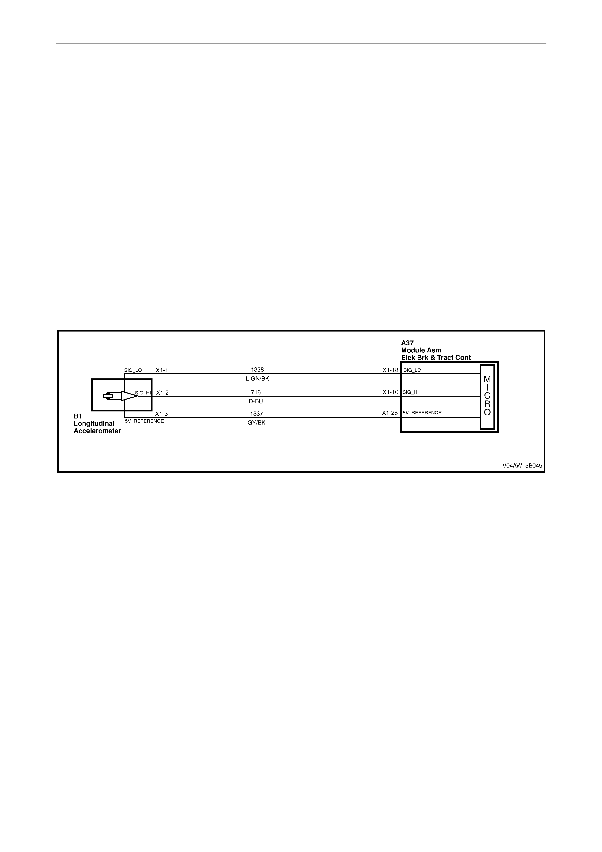
AW D ABS-TCS Page 5B–88
Page 5B–88
7.12 DTC C0191 – Longitudinal Acceleration
Sensor Incorrect Signal
Circuit Descri ption
The ECU supplies 5 volts to the longitudinal accelerometer reference circuit 1337 and ground through low reference
circuit 1338.
The longitudinal accelerometer uses two differential capacitors in conjunction with a sprung mass to produce a signal
voltage. This signal voltage is proportional to the level of vehicle acceleration.
The ECU monitors the longitudinal accelerometer signal voltage circuit 716 to determine the level of vehicle acceleration
or deceleration.
• When the vehicle is stationary, the longitudinal accelerometer signal voltage ranges from 2.4 to 2.6 volts.
• As the vehicle accelerates, the signal voltage increases proportional to the vehicle acceleration with a maximum of
4.7 volts.
• As the vehicle decelerates, the signal voltage decreases in proportion to the vehicle deceleration with a minimum
of 0.4 volt.
If the ECU detects that the longitudinal accelerometer signal voltage is outside the predetermined parameters, DTC
C0191 sets.
Figure 5B – 59
Diagnostic Aids
Conditions for Running DTC C0191
• The ignition is switched on.
Conditions for Setting DTC C0191
• When the ECU detects that the longitudinal accelerometer signal voltage is outside 0.4 – 4.7 volts range for more
than 100 milliseconds.
Action Taken when DTC C0191 Sets
• The ECU disables TCS for the duration of the ignition cycle.
• The ABS wa rning lam p , the ABS warning icon and the trac-off icon activates.
Additional information
• Refer to 4.2 DTCs for information on the conditions for clearing DTCs.
• For intermittent fault conditions, refer to 6 Intermittent Conditions.
• Refer to Figure 5B – 60 for ECU and longitudinal accelerometer connector illustrations.

AW D ABS-TCS Page 5B–89
Page 5B–89
Figure 5B – 60
Test Description
Step 2 This Step verifies that the fault condition currently exists.

AW D ABS-TCS Page 5B–90
Page 5B–90
DTC C0191 Diagnostic Table
Step Action Value(s) Yes No
1 Was the ABS-TCS Main Diagnostic Table performed? – Go to Step 2 Refer to
5.5 ABS-TCS Ma in
Diagnostic Starting
Point.
2 1 Switch off the ignition for 10 seconds.
2 Operate the vehicle within the conditions for
running DTC C0191.
3 Using Tech 2, select the DTC display function.
Did DTC C0191 fail this ignition?
–
Go to Step 3
Refer to DTC C0191
Additional
Information.
3 1 Switch off the ignition.
2 Disconnect the longitudinal accelerometer wiring
connector. Refer to 9.8 Longitudinal
Accelerometer.
3 Switch on the ignition wi th the engine not running.
4 Using a digital multimeter, measure the voltage
between low reference circuit 1338 and 5 volts
reference circuit 1337.
5 Reconnect the longitudinal accelerometer wiring
connector.
Is the voltage near the specified value?
5 volts
Go to Step 4 Go to Step 6
4 1 Switch on the ignition wi th the engine not running.
2 Using a digital multimeter, measure the voltage
between the longitudinal accelerometer signal
circuit 716 and a good ground.
Is the voltage less than the specified value?
0.7 volts
Go to Step 8 Go to Step 5
5 Using a digital multimeter, measure the voltage
between the longitudinal accelerometer signal circuit
716 and a good ground.
Is the voltage greater than the specified range?
4.3 volts
Go to Step 9 Go to Step 10
6 Test the longitudinal accelerometer 5 volt reference
circuit 1337 for a short to voltage, short to ground or an
open circuit condition.
Was any fault found and rectified?
–
Go to Step 14 Go to Step 7
7 Test the longitudinal accelerometer low reference
circuit 1338 for a short to voltage, high resistance or an
open circuit condition.
Was any fault found and rectified?
–
Go to Step 14 Go to Step 11
8 Test the longitudinal accelerometer signal circuit 716
for a short to ground, high resistance or an open circuit
condition.
Was any fault found and rectified?
–
Go to Step 14 Go to Step 10
9 Test the longitudinal accelerometer signal circuit 716
for a short to voltage.
Was any fault found and rectified? – Go to Step 14 Go to Step 10

AW D ABS-TCS Page 5B–91
Page 5B–91
Step Action Value(s) Yes No
10 Inspect for poor connections at the longitudinal
accelerometer wiring connector. Refer to Section 12P
Wiring Diagrams for information on testing wiring
circuits.
Was any fault found and rectified?
–
Go to Step 14 Go to Step 12
11 Inspect for poor connections at the ECU wiring
connector. Refer to Section 12P for information on
testing wiring circuits.
Was any fault found and rectified?
–
Go to Step 14 Go to Step 13
12 Replace the longitudinal accelerometer. Refer to 9.8
Longitudinal Accelerometer.
Was the repair completed? – Go to Step 14 –
13 Replace the ECU . Refer to 9.3 ECU /hydraulic
modulator.
Was the repair completed? – Go to Step 14 –
14 1 Using Tech 2, clear the DTCs.
2 Switch off the ignition for 10 seconds.
3 Operate the vehicle within the conditions for
running DTC C0191.
Did DTC C0191 fail this ignition?
–
Go to Step 2 Go to Step 15
15 Using Tech 2, select the DTC display function.
Are there any DTC displayed? – Go to the
appropriate DTC
Table. System OK
When all diagnosis and repairs are completed, check the system for correct operation.
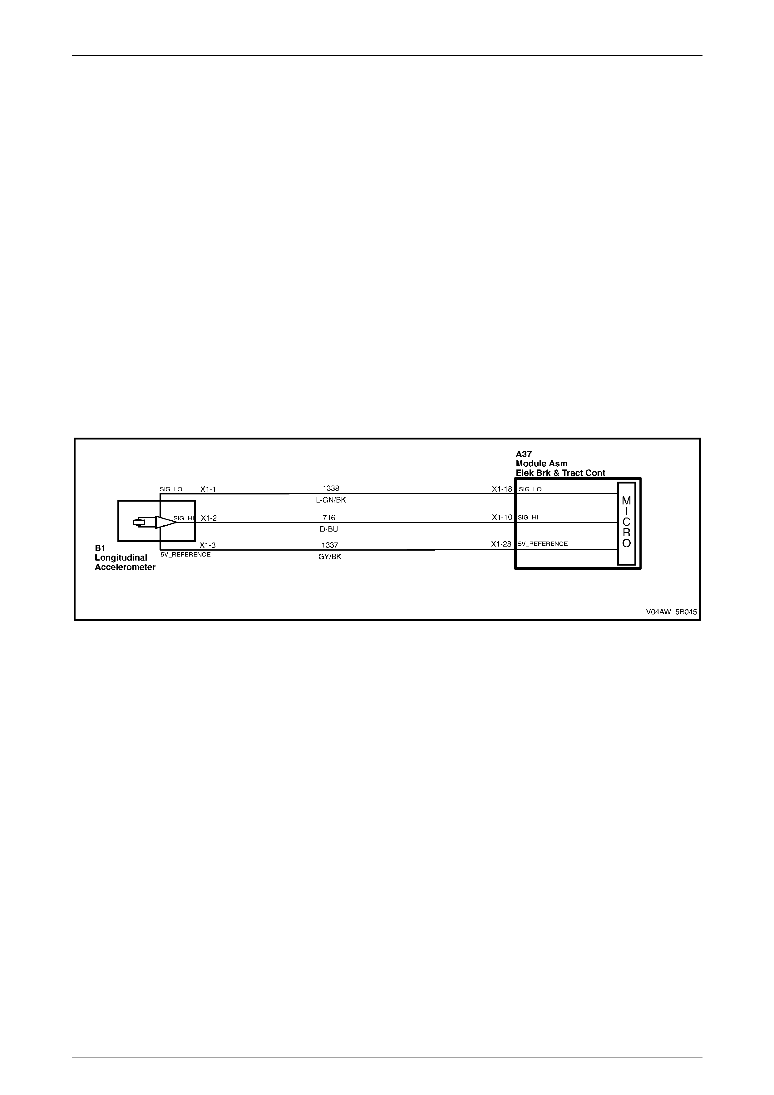
AW D ABS-TCS Page 5B–92
Page 5B–92
7.13 DTC C0192 – Longitudinal Acceleration
Sensor Circuit Malfunction
Circuit Descri ption
The ECU supplies 5 volts to the longitudinal accelerometer through reference circuit 1337 and ground through low
reference circuit 1338.
The longitudinal accelerometer uses two differential capacitors in conjunction with a sprung mass to produce a signal
voltage. This signal voltage is proportional to the level of vehicle acceleration.
The ECU monitors the longitudinal accelerometer signal voltage circuit 716 to determine the level of vehicle acceleration
or deceleration.
• When the vehicle is stationary, the longitudinal accelerometer signal voltage ranges from 2.4 to 2.6 volts.
• As the vehicle accelerates, the signal voltage increases proportional to the vehicle acceleration with a maximum of
4.7 volts.
• As the vehicle decelerates, the signal voltage decreases in proportion to the vehicle deceleration with a minimum
of 0.4 volt.
If the ECU detects that the longitudinal accelerometer signal voltage is changing rapidly under normal driving conditions
or if the ECU determines that the signal voltage is false, the ECU will disregard the signal voltage to prevent a false TCS
brake intervention and will set DTC C0192.
Figure 5B – 61
Diagnostic Aids
Conditions for Running DTC C0192
• The ignition is switched on.
• The vehicle speed is greater than approximately 40 km/h.
Conditions for Setting DTC C0192
• If the ECU detects that the longitudinal accelerometer signal exceeds 0.26g for more than two seconds during a
stable driving condition, the ECU will disregard this signal to prevent a false TCS brake intervention and will log
DTC C0192.
• The ECU monitors and stores the longitudinal accelerometer long time filtered driving direction. This is a straight-
ahead direction and its value is called the offset. The ECU will log DTC C0192 if the offset value exceeds 0.23g.
• The longitudinal accelerometer signal is limited to an electrical stop of 1.8g. If the ECU detects this signal exceeds
1.5g for more than 500 milliseconds, DTC C0192 sets.
• When the vehicle is stationary, the longitudinal accelerometer signal must be less than 0.7g. If the ECU detects
that this signal exceeds 0.7g when the vehicle is stationary, DTC C0192 sets.
• Under normal driving conditions, the longitudinal accelerometer signal must not change more than 55g / second. If
the ECU detects that this signal exceeds 55g / second, DTC C0192 sets.
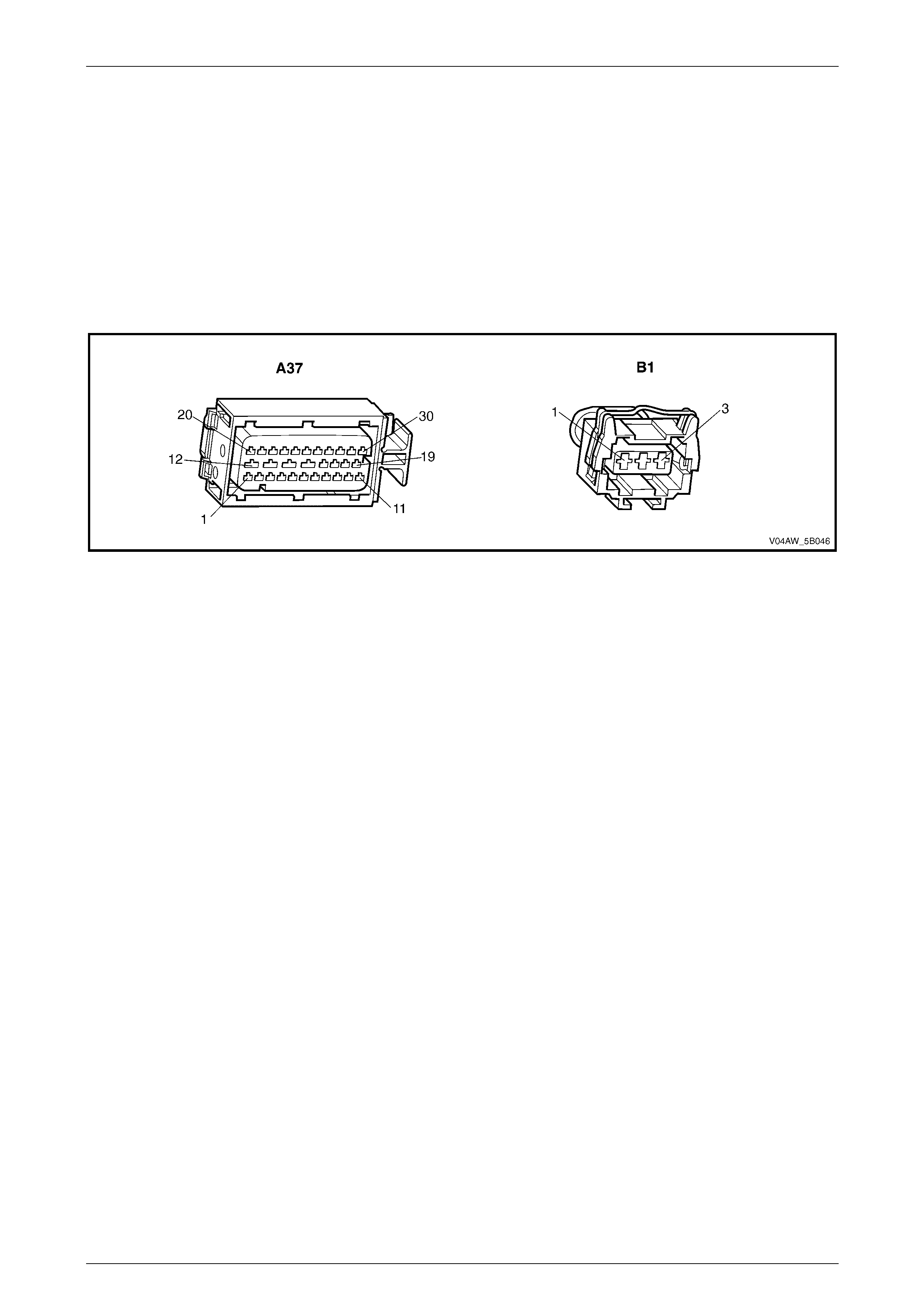
AW D ABS-TCS Page 5B–93
Page 5B–93
Action Taken When DTC C0192 Sets
• The ECU disables TCS for the duration of the ignition cycle.
• The ABS is not disabled.
• The ABS wa rning lam p , the ABS warning icon and the trac-off icon activates.
Additional information
• Refer to 4.2 DTCs for information on the conditions for clearing DTCs.
• For intermittent fault conditions, refer to 6 Intermittent Conditions.
• Refer to Figure 5B – 62 for ECU and longitudinal accelerometer connector illustrations.
Figure 5B – 62

AW D ABS-TCS Page 5B–94
Page 5B–94
DTC C0192 Diagnostic Table
Step Action Value(s) Yes No
1 Was the ABS-TCS Main Diagnostic Table performed? – Go to Step 2 Refer to
5.5 ABS-TCS Ma in
Diagnostic Starting
Point.
2 1 Switch off the ignition for 10 seconds.
2 Operate the vehicle within the conditions for
running DTC C0192.
3 Using Tech 2, select the DTC display function.
Did DTC C0192 fail this ignition?
–
Go to Step 3
Refer to DTC C0192
Additional
Information.
3 1 Switch off the ignition.
2 Disconnect the longitudinal accelerometer wiring
connector. Refer to 9.8 Longitudinal
Accelerometer.
3 Switch on the ignition wi th the engine not running.
4 Using a digital multimeter, measure the voltage
between low reference circuit 1338 and 5 volts
reference circuit 1337.
5 Reconnect the longitudinal accelerometer wiring
connector.
Is the voltage near the specified value?
5 volts
Go to Step 4 Go to Step 6
4 1 Switch on the ignition wi th the engine not running.
2 Using a digital multimeter, measure the voltage
between the longitudinal accelerometer signal
circuit 716 and a good ground.
Is the voltage less than the specified value?
0.7 volts
Go to Step 8 Go to Step 5
5 Using a digital multimeter, measure the voltage
between the longitudinal accelerometer signal circuit
716 and a good ground.
Is the voltage greater than the specified range?
4.3 volts
Go to Step 9 Go to Step 10
6 Test the longitudinal accelerometer 5 volt reference
circuit 1337 for a short to voltage, short to ground or an
open circuit condition.
Was any fault found and rectified?
–
Go to Step 14 Go to Step 7
7 Test the longitudinal accelerometer low reference
circuit 1338 for a short to voltage, high resistance or an
open circuit condition.
Was any fault found and rectified?
–
Go to Step 14 Go to Step 11
8 Test the longitudinal accelerometer signal circuit 716
for a short to ground, high resistance or an open circuit
condition.
Was any fault found and rectified?
–
Go to Step 14 Go to Step 10
9 Test the longitudinal accelerometer signal circuit 716
for a short to voltage.
Was any fault found and rectified? – Go to Step 14 Go to Step 10

AW D ABS-TCS Page 5B–95
Page 5B–95
Step Action Value(s) Yes No
10 Inspect for poor connections at the longitudinal
accelerometer wiring connector. Refer to Section 12P
Wiring Diagrams for information on testing wiring
circuits.
Was any fault found and rectified?
–
Go to Step 14 Go to Step 12
11 Inspect for poor connections at the ECU wiring
connector. Refer to Section 12P for information on
testing wiring circuits.
Was any fault found and rectified?
–
Go to Step 14 Go to Step 13
12 Replace the longitudinal accelerometer. Refer to
9.8 Longitudinal Accelerometer.
Was the repair completed? – Go to Step 14 –
13 Replace the ECU . Refer to 9.3 ECU /hydraulic
modulator.
Was the repair completed? – Go to Step 14 –
14 1 Using Tech 2, clear the DTCs.
2 Switch off the ignition for 10 seconds.
3 Operate the vehicle within the conditions for
running DTC C0192.
Did DTC C0192 fail this ignition?
–
Go to Step 2 Go to Step 15
15 Using Tech 2, select the DTC display function.
Are there any DTC displayed? – Go to the
appropriate DTC
Table. System OK
When all diagnosis and repairs are completed, check the system for correct operation.
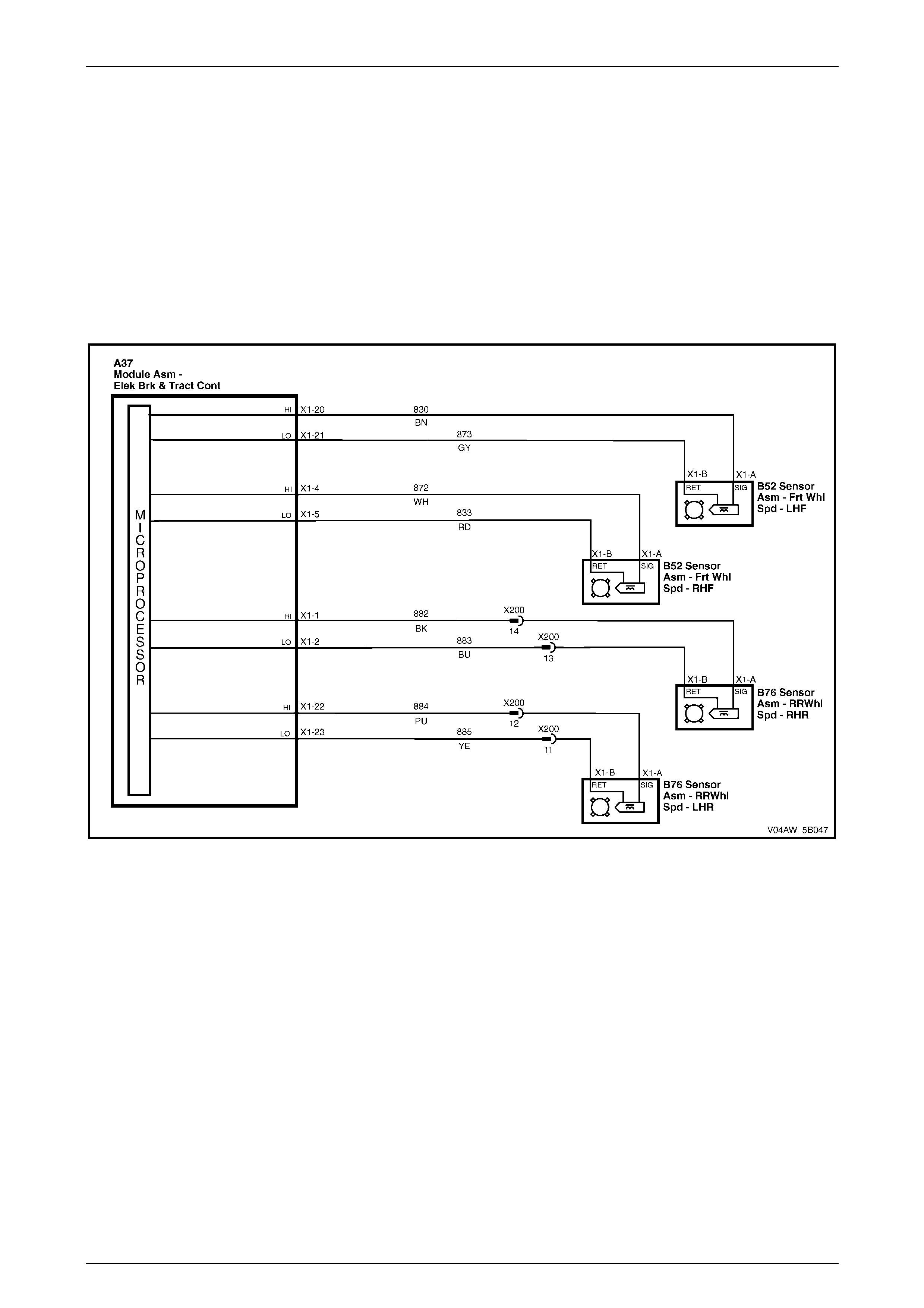
AW D ABS-TCS Page 5B–96
Page 5B–96
7.14 DTC C0245 – Wheel Speed Signal
Malfunction
Circuit Descri ption
The ECU supplies ground to the left wheel speed sensor low reference circuit.
The wheel speed sensor in conjunction with a pulse ring generates an AC signal voltage. The amplitude and frequency
of the signal generated is proportional to the wheel speed. The ECU monitors the wheel speed sensor signal voltage to
determine the speed of each wheel.
DTC C0245 sets if the ECU detects a fault in the wheel speed sensor circuit but cannot identify the specific wheel speed
sensor triggering the fault condition.
Figure 5B – 63
Diagnostic Aids
Conditions for Running DTC C0245
• The ignition is switched on.
• The ECU Self-test Initialisation Sequence is complete.
Conditions for Setting DTC C0245
DTC 245 sets If the EBCM detects that there is a deviation of more than 6 km/h between a wheel speed and the vehicle
speed and the ECU cannot specifically identify which wheel speed sensor is causing the fault condition.
Once the ECU identifies the wheel speed sensor that triggers DTC C0245, it will take the following actions:
• The ECU will set the DTC that represents the faulty wheel speed sensor.
• The ECU will designate DTC C0245 as a history DTC.
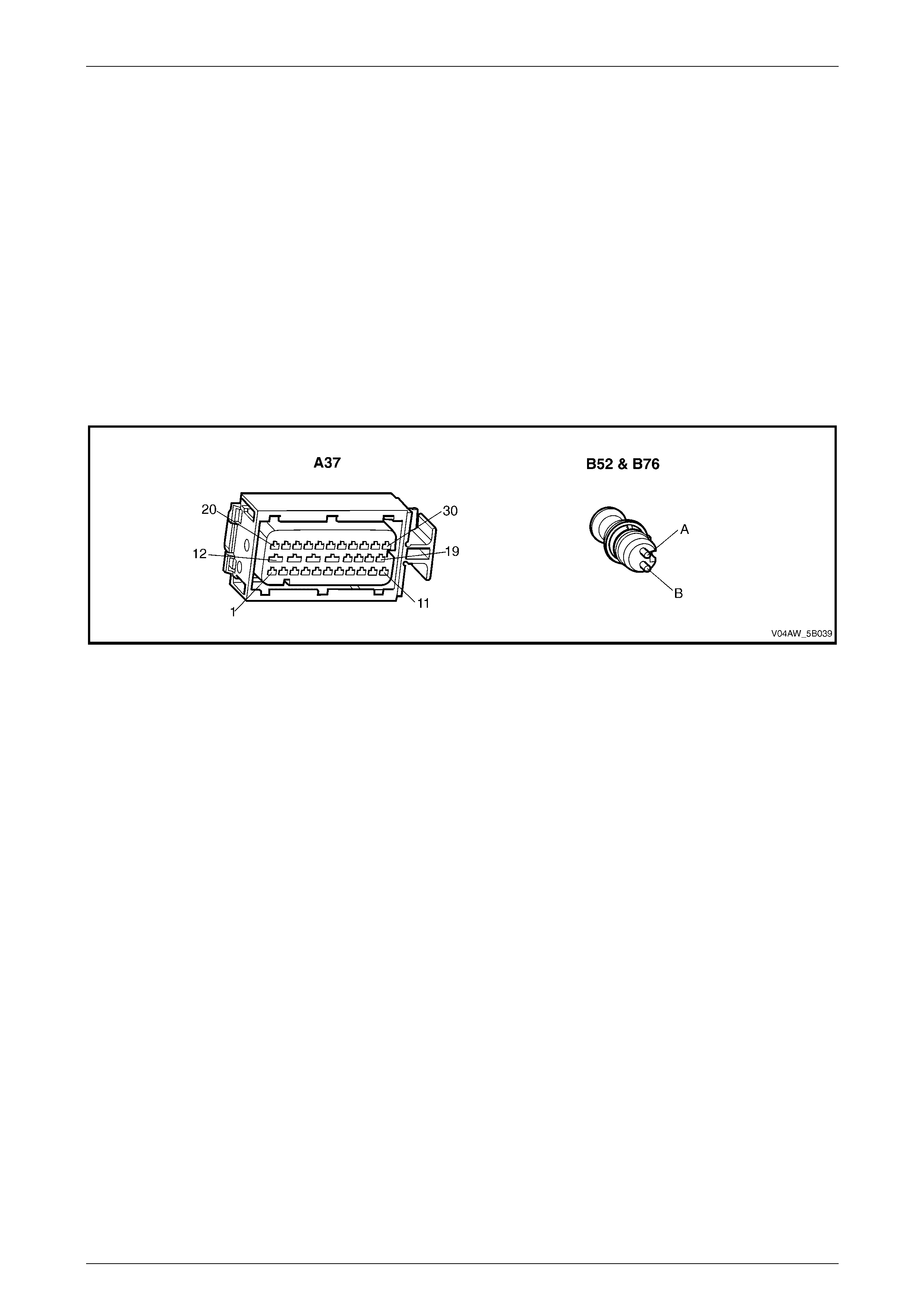
AW D ABS-TCS Page 5B–97
Page 5B–97
Action Taken when DTC C0245 Sets
• The ECU disables the ABS-TCS for the duration of the ignition cycle if the exact fault can be determined and after
the ABS-TCS cycle has terminated.
• The ABS wa rning lam p , the ABS warning icon and the trac-off icon activates.
• The brake failure lamp activates.
Additional information
• Refer to 4.2 DTCs for information on the conditions for clearing DTCs.
• High voltage or high current devices such as spark plugs and spark plug wires may induce electrical noise on the
front left wheel speed sensor circuit. This electrical noise can interfere with normal wheel speed sensor operation.
Ensure that the wheel speed sensor wiring harness is routed away from these high voltage or high current
devices.
• For intermittent fault condition, refer to 6 Intermittent Conditions.
• Refer to Figure 5B – 64 for the ECU and wheel speed sensor connector illustrations.
Figure 5B – 64
Test Description
Step 2 This Step verifies if the fault is currently present.
Step 3 This Step tests the front left wheel speed sensor internal circuitry.
Step 5 This Step tests the front left wheel speed sensor output voltage.

AW D ABS-TCS Page 5B–98
Page 5B–98
DTC C0245 Diagnostic Table
Step Action Value(s) Yes No
1 Was the ABS-TCS Main Diagnostic Table performed? – Go to Step 2 Refer to
5.5 ABS-TCS Ma in
Diagnostic Starting
Point.
2 Using Tech 2, view current and history DTCs.
Are any of the following DTCs set as a current or a
history DTC?
• DTC C0036
• DTC C0041
• DTC C0046
• DTC C0051
–
Refer to the
appropriate wheel
speed sensor DTC
Diagnostic Table Go to Step 3
3 1 Raise the front and rear of the vehicle and
support on safety stands. Refer to Section 0A
General Information for location of the jacking
points.
2 Inspect all wheel speed sensors, their pulse ring
and wiring harness for signs of physical damage
or conditions that may trigger intermittent fault.
Refer to 6 AWD ABS-TCS Intermittent Fault
Conditions.
Was any fault found and rectified?
–
Go to Step 7 Go to Step 4
4 1 Connect an oscilloscope to the front left wheel
speed sensor connector terminals.
2 Spin the front left wheel.
3 Observe the wheel speed sensor output signal
display. Refer to 3.3 Wheel Speed Sensor.
4 Perform the testing procedure to the remaining
wheel speed sensors.
NOTE
If an oscilloscope is not available, perform
the following visual inspection:
1 Inspect the front left wheel speed sensor
pulse ring for damaged teeth
2 While rotating the front left wheel, check the
wheel speed sensor alignment to the pulse
ring.
3 Check the front left wheel speed sensor run-
out.
4 Check the front left wheel speed sensor or
pulse ring for dirt or other contaminants that
may affect its operation.
5 Perform the visual inspection procedure to
the remaining wheel speed sensors.
Was any fault found and rectified?
–
Go to Step 7 Go to Step 5

AW D ABS-TCS Page 5B–99
Page 5B–99
Step Action Value(s) Yes No
5 1 Using Tech 2, observe the Freeze Frame / Failure
Record for this DTC.
2 Switch off the ignition for 10 seconds.
3 Road test the vehicle within the conditions for
running this DTC or within the conditions in the
Freeze Frame/Failure Record.
Did any of the wheel speed sensors trigger this DTC?
– Refer to the
appropriate wheel
speed sensor DTC
Diagnostic Table Go to Step 6
6 Replace the ECU . Refer to 9.3 ECU /hydraulic
modulator.
Was the repair completed? – Go to Step 7 –
7 1 Using Tech 2, clear the DTCs.
2 Switch off the ignition for 10 seconds.
3 Operate the vehicle within the conditions for
running DTC C0245.
Did DTC C0245 fail this ignition?
–
Go to Step 2 Go to Step 8
8 Using Tech 2, select the DTC display function.
Are there any DTC displayed? – Go to the
appropriate DTC
Table. System OK
When all diagnosis and repairs are completed, check the system for correct operation.

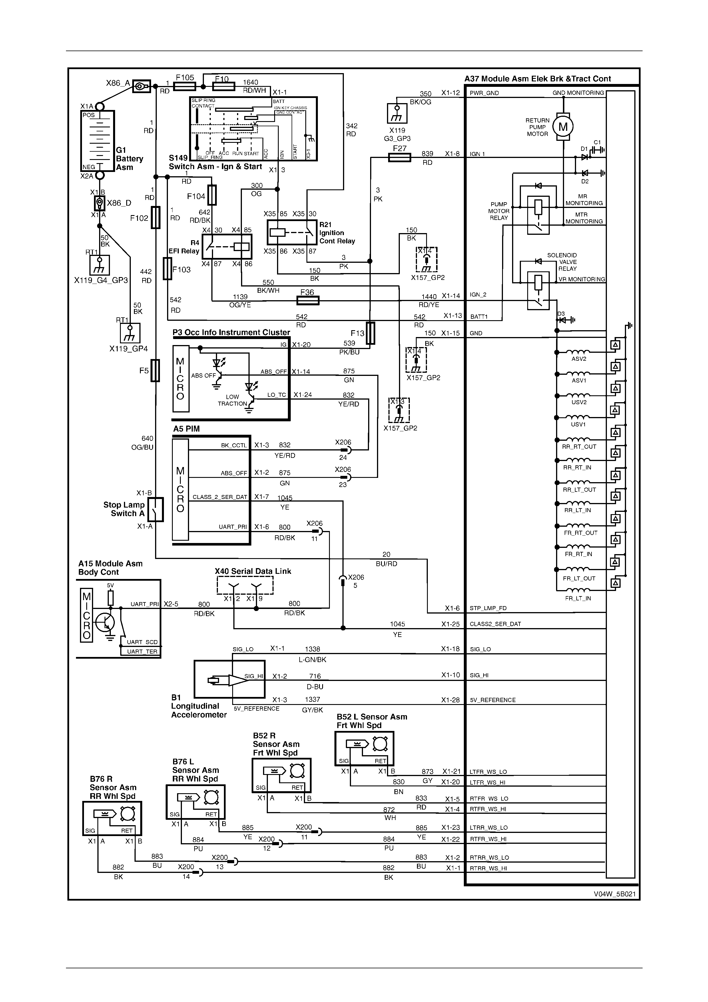
AW D ABS-TCS Page 5B–101
Page 5B–101
Figure 5B – 65
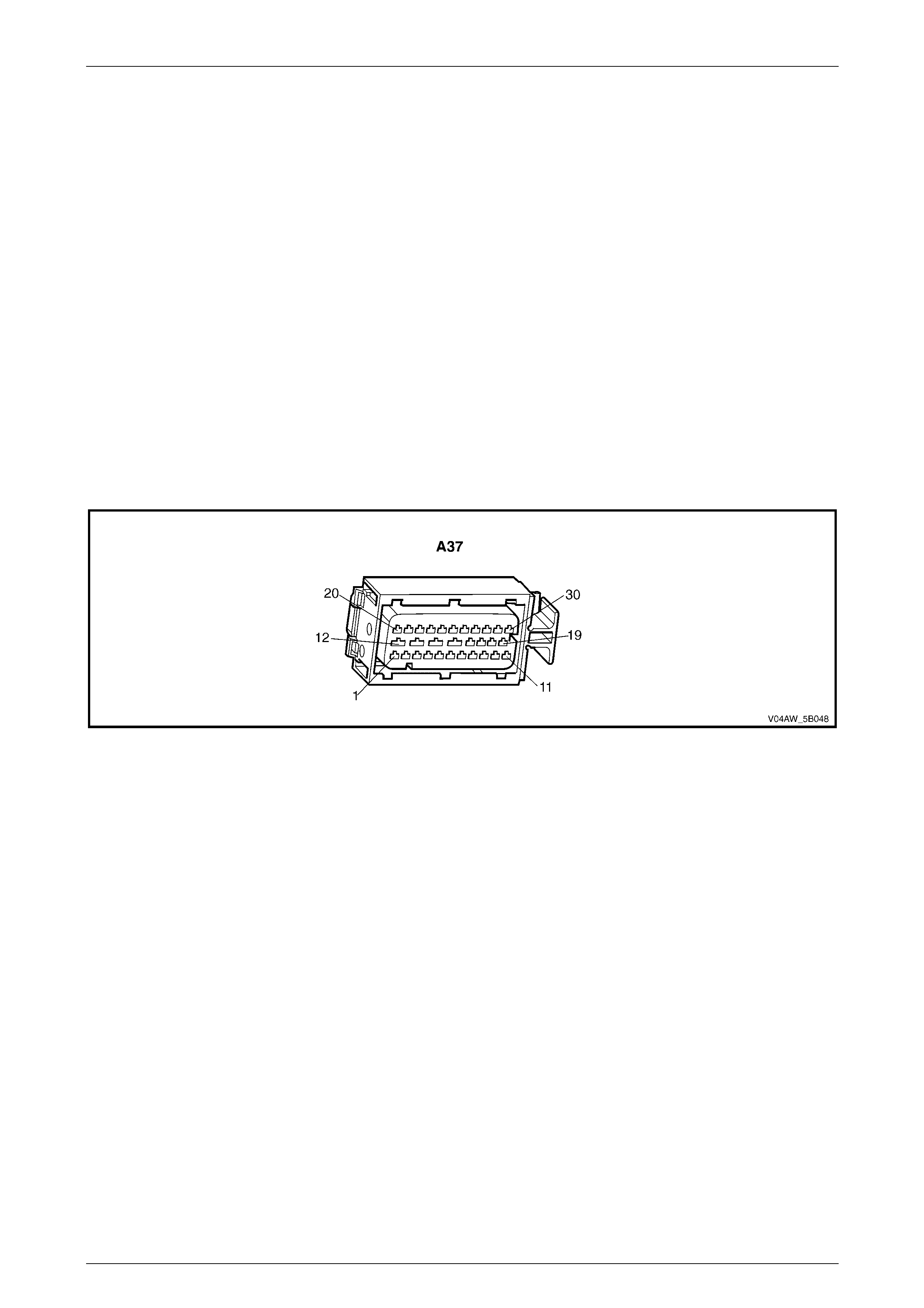
AW D ABS-TCS Page 5B–102
Page 5B–102
Diagnostic Aids
Conditions for Running DTC C0550
• The ignition is switched on.
Conditions for Setting DTC C0550
• DTC C0550 sets when an internal ECU fault or solenoid malfunction exists.
Action Taken when DTC C0550 Sets
• The ECU disables the ABS-TCS for the duration of the ignition cycle.
• The ABS wa rning lam p , the ABS warning icon and the trac-off icon activates.
• The brake failure lamp may activate.
Additional information
• Refer to 4.2 DTCs for information on the conditions for clearing DTCs.
• For intermittent fault conditions, refer to 6 Intermittent Conditions.
• Refer to Figure 5B –66 for ECU connector illustration.
Figure 5B – 66
Test Description
Step 2 This Step verifies that there are no other related DTC present that may trigger DTC C0550 or if there are other
fault that may cause a replacement ECU to malfunction.
Step 4 This Step ensures that there is no fault in the ABS fuses. A blown ABS fuse may trigger this DTC.

AW D ABS-TCS Page 5B–103
Page 5B–103
DTC C0550 Diagnostic Table
Step Action Value(s) Yes No
1 Was the ABS-TCS Main Diagnostic Table performed? – Go to Step 2 Refer to
5.5 ABS-TCS Ma in
Diagnostic Starting
Point.
2 Using Tech 2, view DTC list.
Are any other DTCs present besides DTC C0550? – Refer to appropriate
DTC table. Go to Step 3
3 1 Switch off the ignition for 10 seconds.
2 Operate the vehicle within the conditions for
setting DTC C0550.
3 Using Tech 2, select the DTC display function.
Did DTC C0550 fail this ignition?
–
Go to Step 4
Refer to DTC C0550
Additional
Information.
4 Test the ABS fuses and replace if required. Refer to
3.7 ABS-TCS fuse locations.
Was any fault found and rectified? – Go to Step 6 Go to Step 5
5 Replace the ECU . Refer to 9.3 ECU /hydraulic
modulator.
Was the repair completed? – Go to Step 6 –
6 1 Using Tech 2, clear the DTCs.
2 Switch off the ignition for 10 seconds.
3 Operate the vehicle within the conditions for
running DTC C0550.
Did DTC C0550 fail this ignition?
–
Go to Step 2 Go to Step 6
7 Using Tech 2, select the DTC display function.
Are there any DTC displayed? – Go to the
appropriate DTC
Table. System OK
When all diagnosis and repairs are completed, check the system for correct operation.
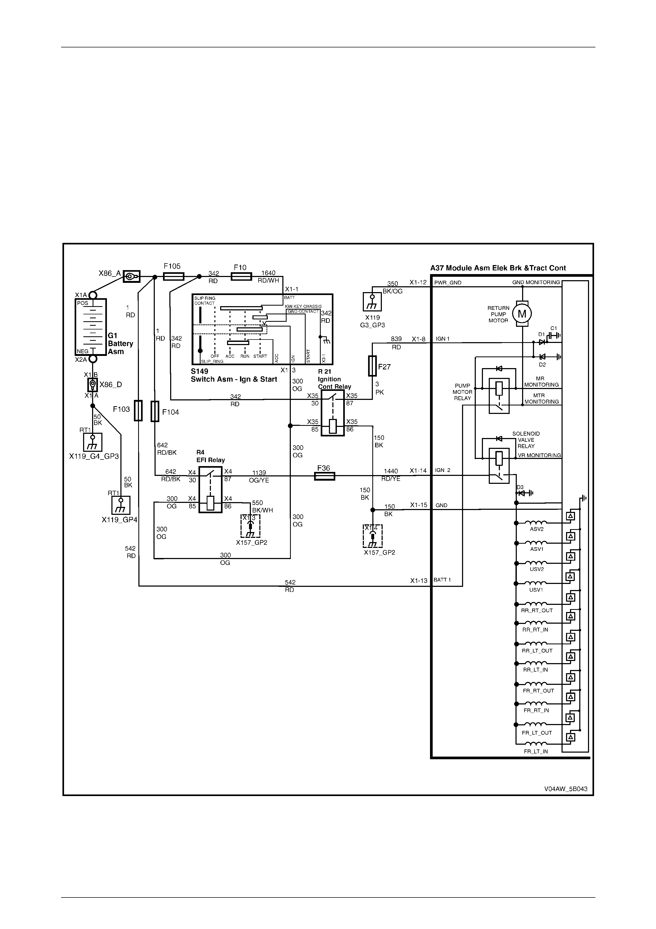
AW D ABS-TCS Page 5B–104
Page 5B–104
7.16 DTC C0896 – Battery Voltage Out of
Range
Circuit Descri ption
The ECU monitors the battery supply voltage available to the ABS-TCS. If the voltage available to the ECU is out of the
specified range, the following fault condition may occur:
• A low battery supply voltage to the ECU may cause incorrect ABS-TCS operation.
• A battery supply voltage to the ECU that is too high may cause damage to the ABS-TCS components.
If the ECU detects that the battery supply voltage is out of range, it sets DTC C0896.
Figure 5B – 67
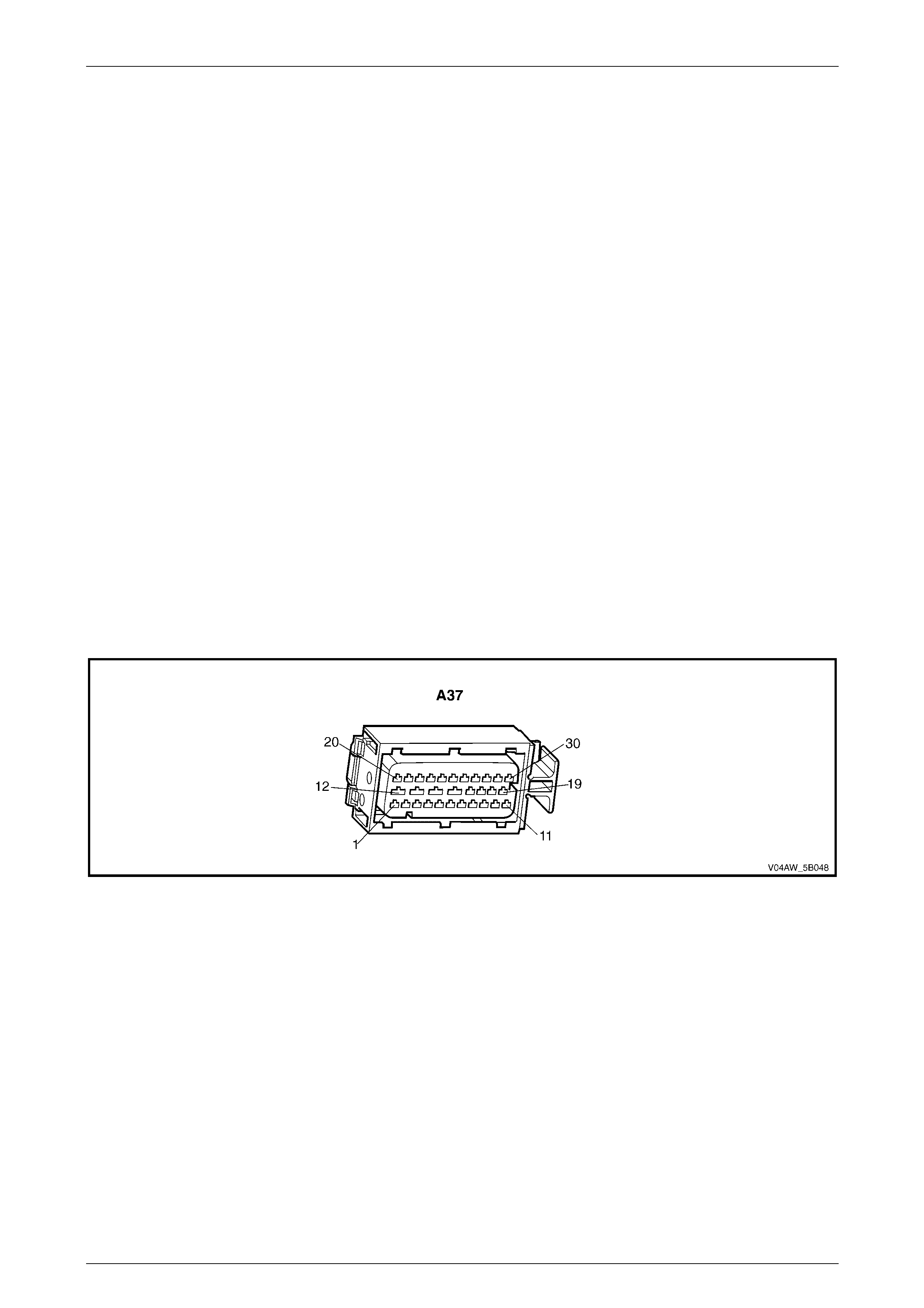
AW D ABS-TCS Page 5B–105
Page 5B–105
Diagnostic Aids
Conditions for Running DTC C0896
• The ignition is switched on.
Conditions for Setting DTC C0896
• When the ECU battery supply voltage meets one of the following conditions for more than 500 milliseconds with
the vehicle speed above 6 km/h:
• If the ECU battery supply voltage drops below 9.4 volts and the ABS-TCS is not active.
• If the ECU battery supply voltage drops below 8.8 volts and the ABS-TCS is active.
• If the ECU battery supply voltage exceeds 17.4 volts regardless of the ABS-TCS mode.
Action Taken when DTC C0110 Sets
• The ECU disables the ABS-TCS for the duration of the ignition cycle.
• The ABS wa rning lam p , the ABS warning icon and the trac-off icon activates.
• The brake failure lamp may activate.
Additional information
• Refer to 4.2 DTCs for information on the conditions for clearing DTCs.
• For intermittent fault conditions, refer to 6 Intermittent Conditions.
• Thorough inspection of the battery and the charging system must be performed. Refer to Section 6D3–1 Charging
System and Section 12A Battery and Cables.
• Refer to Figure 5B – 68 for ECU connector illustration.
Figure 5B – 68
Test Description
Step 2 This tests verifies if a fault exists in the battery or charging system.

AW D ABS-TCS Page 5B–106
Page 5B–106
DTC C0896 Diagnostic Table
Step Action Value(s) Yes No
1 Was the ABS-TCS Main Diagnostic Table performed? – Go to Step 2 Refer to
5.5 ABS-TCS Ma in
Diagnostic Starting
Point.
2 Check the charging system and the battery. Refer to
Section 6D3–1 Charging System and Section 12A
Battery and Cables.
Was any fault found and rectified?
–
Go to Step 10 Go to Step 3
3 1 Switch off the ignition for 10 seconds.
2 Operate the vehicle within the conditions for
setting DTC C00896.
3 Using Tech 2, select the DTC display function.
Did DTC C0896 fail this ignition?
–
Go to Step 4
Refer to DTC C0896
Additional
Information.
4 1 Switch off the ignition.
2 Disconnect the ECU wiring connector.
3 Switch on the ignition wi th the engine not running.
4 Using a digital multimeter, measure the voltage
between Tool No. J 3970 530 terminal 15 and
terminal 8.
Is the voltage below the specified value?
9.4 volts
Go to Step 5
Refer to DTC C0896
Additional
Information.
5 Using a digital multimeter, measure the resistance
between Tool No. J 3970 530 terminal 15 and a good
ground.
Is the resistance within the specified range?
0–5 Ω
Go to Step 7 Go to Step 6
6 Repair the open or high resistance condition in the ECU
ground circuit
Was any fault found and rectified? – Go to Step 10 Go to Step 8
7 Check for a short to ground, open or high resistance
condition in the ECU ignition voltage supply circuit 839.
Was any fault found and rectified? – Go to Step 10 Go to Step 8
8 Inspect for poor connections at the ECU wiring
connector. Refer to Section 12P for information on
testing wiring circuits.
Was any fault found and rectified?
–
Go to Step 10 Go to Step 9
9 Replace the ECU . Refer to 9.3 ECU /hydraulic
modulator.
Was the repair completed? – Go to Step 10 –
10 1 Using Tech 2, clear the DTCs.
2 Switch off the ignition for 10 seconds.
3 Operate the vehicle within the conditions for
running DTC C0896.
Did DTC C0896 fail this ignition?
–
Go to Step 2 Go to Step 11
11 Using Tech 2, select the DTC display function.
Are there any DTC displayed? – Go to the
appropriate DTC
Table. System OK
When all diagnosis and repairs are completed, check the system for correct operation.

AW D ABS-TCS Page 5B–107
Page 5B–107
8 AWD ABS-TCS Serial Data
Communication Diagnostics
8.1 Serial Data Communication
Preliminary Diagnostic Table
Circuit Descri ption
The various electronic control modules integrated into the MY 2004 VY AW D Wagon vehicles communicate with each
other through the Serial Data Bus where the Body Control Module (BCM) is the Bus Master. Refer to Section 12J Body
Control Module for further information on the serial data communication.
The Electronic Control Unit (ECU) and the Powertrain Control Module (PCM) transmit and receive data using Class 2
Serial Data protocol while the BCM and other vehicle control modules use the Universal Asynchronous Receive and
Transmit (UART) protocol.
As the Class 2 Serial Data protocol is not compatible with the UART protocol, a Powertrain Interface Module (PIM) is
integrated to the data link communication system to perform the following tasks: (Refer to Section 6C3 Powertrain
Management System for further information on the PIM)
• Translate the Class 2 Serial Data transmitted by ECU and the PCM into UART protocol that can be received and
recognised by the BCM and the Instrument Cluster Assembly.
• Translate the UART Data transmitted by the BCM into a Class 2 Serial Data protocol that can be receive and
recognised by the ECU and the PCM.
The AWD ABS-TCS Data Link Communication Diagnostics is organised in a logical structure that begins with the AWD
ABS-TCS Data Link Communication Preliminary Tests.
The AWD ABS-TCS Data Link Preliminary Tests identifies and compiles other DTCs that are related to the BCM, PCM,
PIM or Instrument Cluster Assembly serial data communication system to provide a more comprehensive diagnostic
procedure.
A fault condition in the Serial Data Bus circuit may trigger any or all of the following DTCs:
• ABS-TCS DTC
• DTC U1000 – No Serial Data from PIM
• DTC U1016 – No Serial Data from PCM
• DTC U1300 and DTC U1301 – Class 2 Data Link Input Too High or Too Low
• BCM DTC
• DTC 7 – No Serial Data from PCM
• DTC 26 – No Serial Data from ABS-TCS
• DTC 27 – No Serial Data from Instruments
• PIM DTC
• U1000 – No Class 2 Serial Data
• U1001 – No Serial Data from PCM
• U1043 – No Serial Data from ABS-TCS
• U1064 – No Serial Data from PCM
• Instrume nt Cluster DTC
• DTC 8 – No Serial Data from ABS-TCS
• DTC 9 – No Serial Data from BCM
• DTC 10 – No Serial Data from OCC
• DTC 11 – No Serial Data from PCM
• DTC 12 – No Serial Data from SDM
• DTC 13 – No Instrument Poll from BCM
• DTC 14 – No Serial Data

AW D ABS-TCS Page 5B–108
Page 5B–108
Correctly identifying all serial data communication circuit related DTCs provides an overall view of the extent of the fault
condition. The following is an example of a communication circuit DTC diagnostic procedure.
• If only DTC U1016 – No Serial Data from PCM is set, the diagnostic procedure will be directed towards testing the
ABS-TCS communication circuit.
• If DTC U1016 – No Serial Data from PCM is set together with the following DTCs which shares a common
communication circuit, the PCM may be the cause of the fault condition and diagnostic procedure will be guided to
test the shared communication circuit.
• BCM DTC 7 – No Serial Data from PCM
• PIM U1001 – No Serial Data from PCM
• Instrument Cluster DTC 11 – No Serial Data from PCM
Therefore, the service technician must have a good understanding of the serial data communication system to reduce
diagnostic time and to prevent misdiagnosis.
Diagnostic Aids
Additional information
• Refer to 4.2 DTCs for information on the conditions for clearing DTCs.
• For intermittent fault conditions, refer to 6 Intermittent Conditions.
• Test the ECU that fails to communicate in Step 3 for the followi ng:
• Test all ground circuits of the ECU for a high resistance or an open circuit condition.
• Test for blown ECU fuses.
• Test the ECU battery supply voltage for a high resistance, open circuit or short to ground condition.
Test Description
Step 3 This Step attempts to compile communication related DTCs.

AW D ABS-TCS Page 5B–109
Page 5B–109
Serial Data Communication Pre liminary Diagnostic Table
Step Action Value(s) Yes No
1 Connect Tech 2 to the DLC.
Does Tech 2 power up? – Go to Step 2
Refer to 6, Tech 2
Diagnosis in
Section 0C
2 1 Using Tech 2, view all DTCs.
2 Record DTCs set by each module.
Are any other DTCs present besides the ABS-TCS
Serial Data communication circuit DTCs ?
–
Go to Step 3
Refer to the
appropriate ABS-
TCS serial data
communication
circuit DTC.
3 1 Switch on the ignition wi th the engine not running.
2 Attempt to communicate with the ECU, BCM,
PCM, PIM and the Instrument Cluster Assembly.
Did any ECU fail to communicate?
–
Refer to the
appropriate ECU
Section or to 4.2
Serial Data
Communication In
Section 12J. Go to Step 4
4 1 Using Tech 2, clear the DTCs.
2 Switch off the ignition for 10 seconds.
3 Operate the vehicle within the conditions for
running the serial data communication DTC
recorded.
Did any of the recorded DTC fail this ignition?
–
Go to Step 2 Go to Step 5
5 Using Tech 2, select the DTC display function.
Are there any DTC displayed? – Go to the
appropriate DTC
Table. System OK
When all diagnosis and repairs are completed, check the system for correct operation.
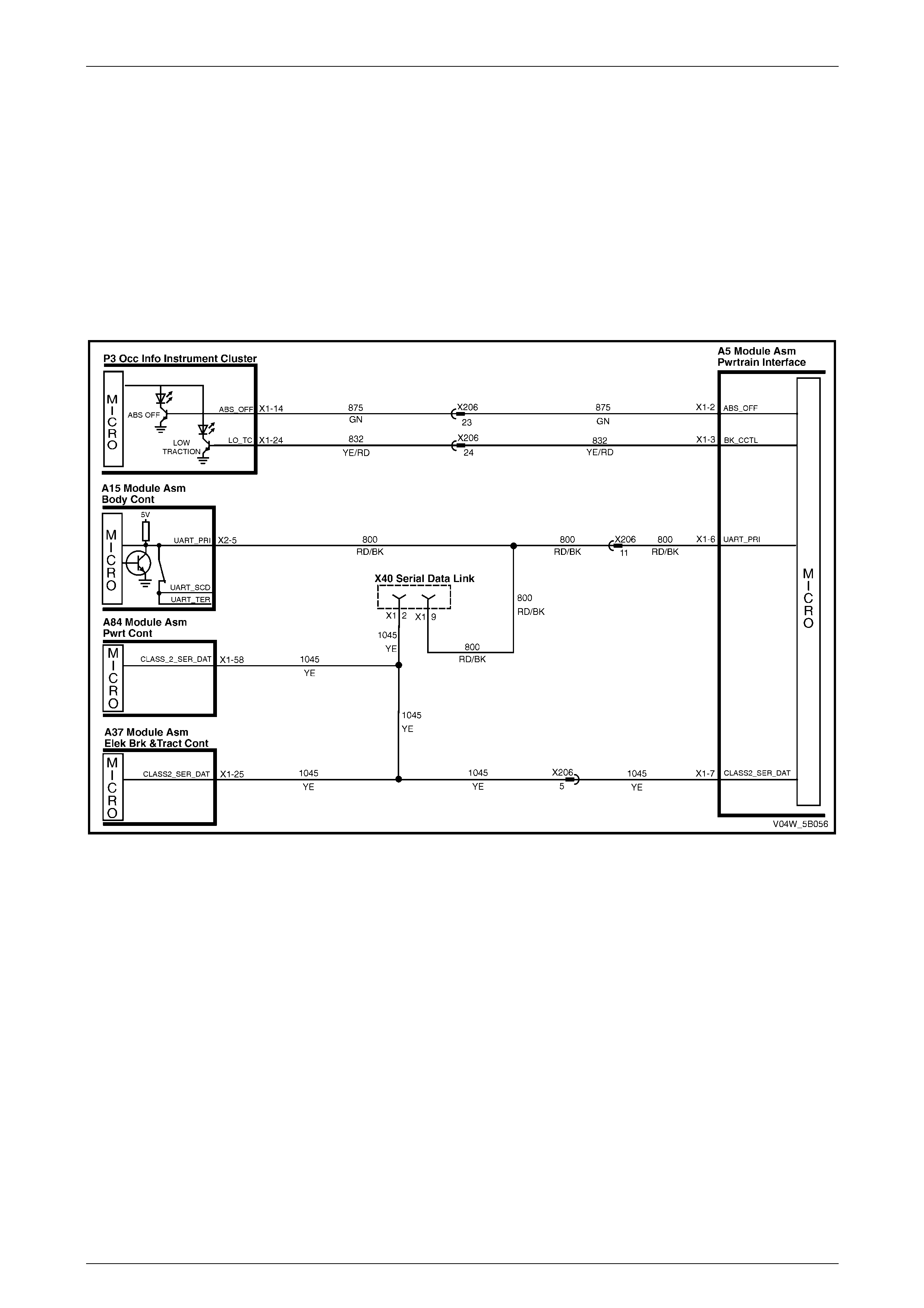
AW D ABS-TCS Page 5B–110
Page 5B–110
8.2 DTC U1000–No Serial Data
Circuit Descri ption
The Electronic Control Unit (ECU) communicates information with the various electronic control modules integrated into
the vehicle through the Serial Data Bus
The ECU and the Powertrain Control Module (PCM) transmit and receive data using Class 2 Serial Data protocol while
the BCM and other vehicle control modules use the Universal Asynchronous Receive and Transmit (UART) protocol.
As the Class 2 Serial Data protocol is not compatible with the UART protocol, a Powertrain Interface Module (PIM) is
integrated to the data link communication system.
If the ECU does not receive serial data during an ignition cycle, DTC U1000 sets.
Figure 5B – 69
Diagnostic Aids
Conditions for Running DTC U1000
The ignition is switched on.
Conditions for Setting DTC U1000
If the ECU does not receive serial data from the PCM during an ignition cycle.
Action Taken when DTC U1000 Sets
• The ECU uses default values for all parameters on the Class 2 serial data circuit.
• The ABS wa rning lam p , the ABS warning icon and the trac-off icon activates.
• The brake failure lamp activates.
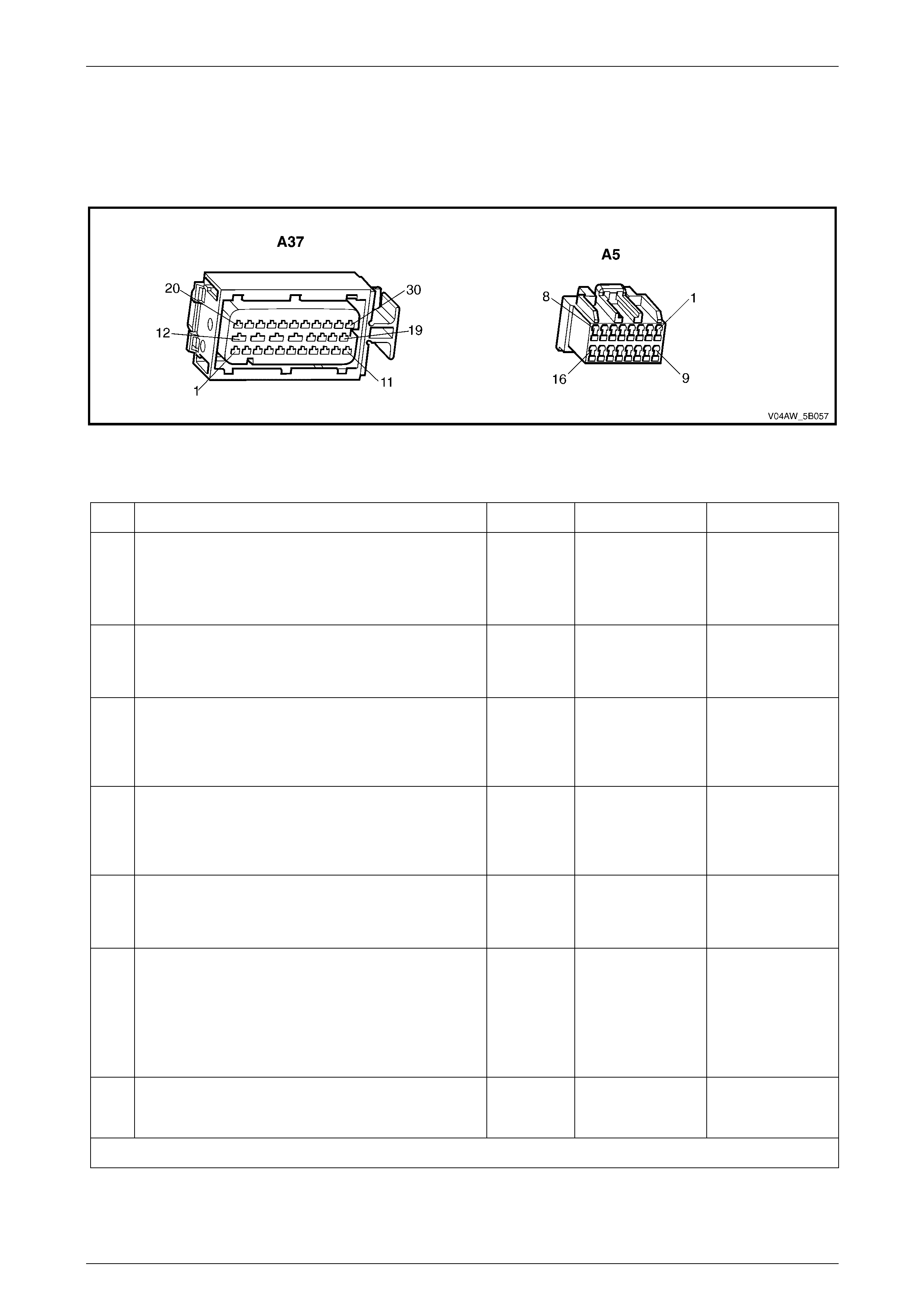
AW D ABS-TCS Page 5B–111
Page 5B–111
Additional information
• Refer to 4.2 DTCs for information on the conditions for clearing DTCs.
• For intermittent fault conditions, refer to 6 Intermittent Conditions.
• Refer to Figure 5B – 70 for ECU connector illustration.
Figure 5B – 70
DTC U1000 Diagnostic Table
Step Action Value(s) Yes No
1 Was the Serial Data Communication Preliminary
Diagnostic Table performed? – Go to Step 2 Refer to
8.1 Serial Data
Communication
Preliminary
Diagnostic Table.
2 Test the Class 2 serial data circuit 1045 for an open
circuit fault condition.
Was any fault found and rectified? – Go to Step 6 Go to Step 3
3 Inspect for poor wiring connection at the PIM wiring
connector. Refer to Section 12P Wiring Diagrams for
information on testing wiring circuits.
Was any fault found and rectified?
–
Go to Step 6 Go to Step 4
4 Inspect for poor connections at the ECU wiring
connector. Refer to Section 12P Wiring Diagrams for
information on testing wiring circuits.
Was any fault found and rectified?
–
Go to Step 6 Go to Step 5
5 Replace the ECU. Refer to 9.3 ECU /hydraulic
modulator.
Was the repair completed? – Go to Step 6 –
6 1 Using Tech 2, clear the DTCs.
2 Switch off the ignition for 10 seconds.
3 Operate the vehicle within the conditions for
running DTC U1000.
Did DTC U1000 fail this ignition?
–
Go to Step 2 Go to Step 7
7 Using Tech 2, select the DTC display function.
Are there any DTC displayed? – Go to the
appropriate DTC
Table. System OK
When all diagnosis and repairs are completed, check the system for correct operation.
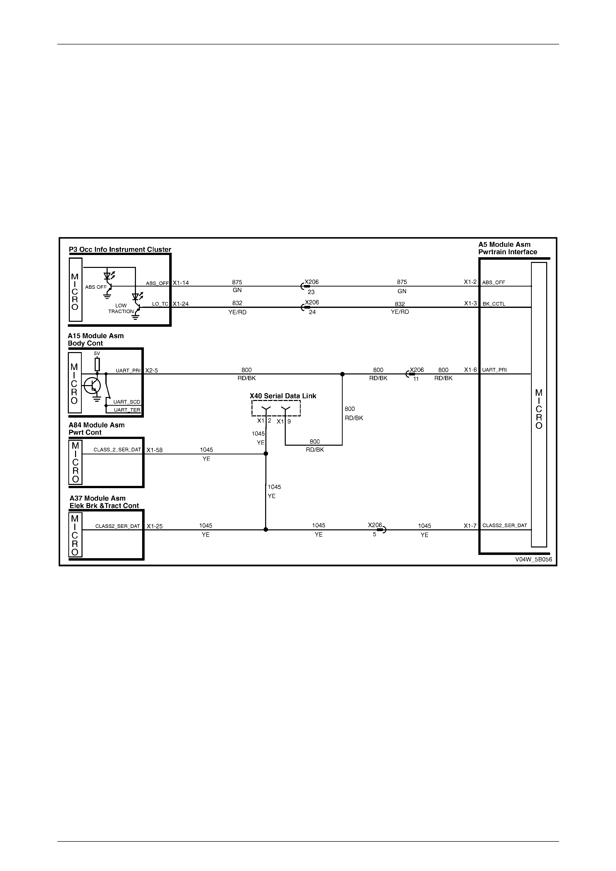
AW D ABS-TCS Page 5B–112
Page 5B–112
8.3 DTC U1016–No Serial Data from PCM
Circuit Descri ption
The Electronic Control Unit (ECU) communicates information with the various electronic control modules integrated into
the vehicle through the Serial Data Bus
The ECU and the Powertrain Control Module (PCM) transmit and receive data using Class 2 Serial Data protocol while
the BCM and other vehicle control modules use the Universal Asynchronous Receive and Transmit (UART) protocol.
As the Class 2 Serial Data protocol is not compatible with the UART protocol, a Powertrain Interface Module (PIM) is
integrated to the data link communication system.
If the ECU does has initially received serial data communication from the PCM and the communication failed during an
ignition cycle, DTC U1016 sets.
Figure 5B – 71
Diagnostic Aids
Conditions for Running DTC U1016
• The ignition is switched on.
• DTC U1000 is not set.
Conditions for Setting DTC U1016
If the ECU does has initially received serial data communication from the PCM and the communication failed during an
ignition cycle.
Action Taken when DTC U1016 Sets
• The ECU uses default values for all parameters on the Class 2 serial data circuit.
• The ABS wa rning lamp, the ABS warning icon and the trac-off icon activates.
• The brake failure lamp activates.
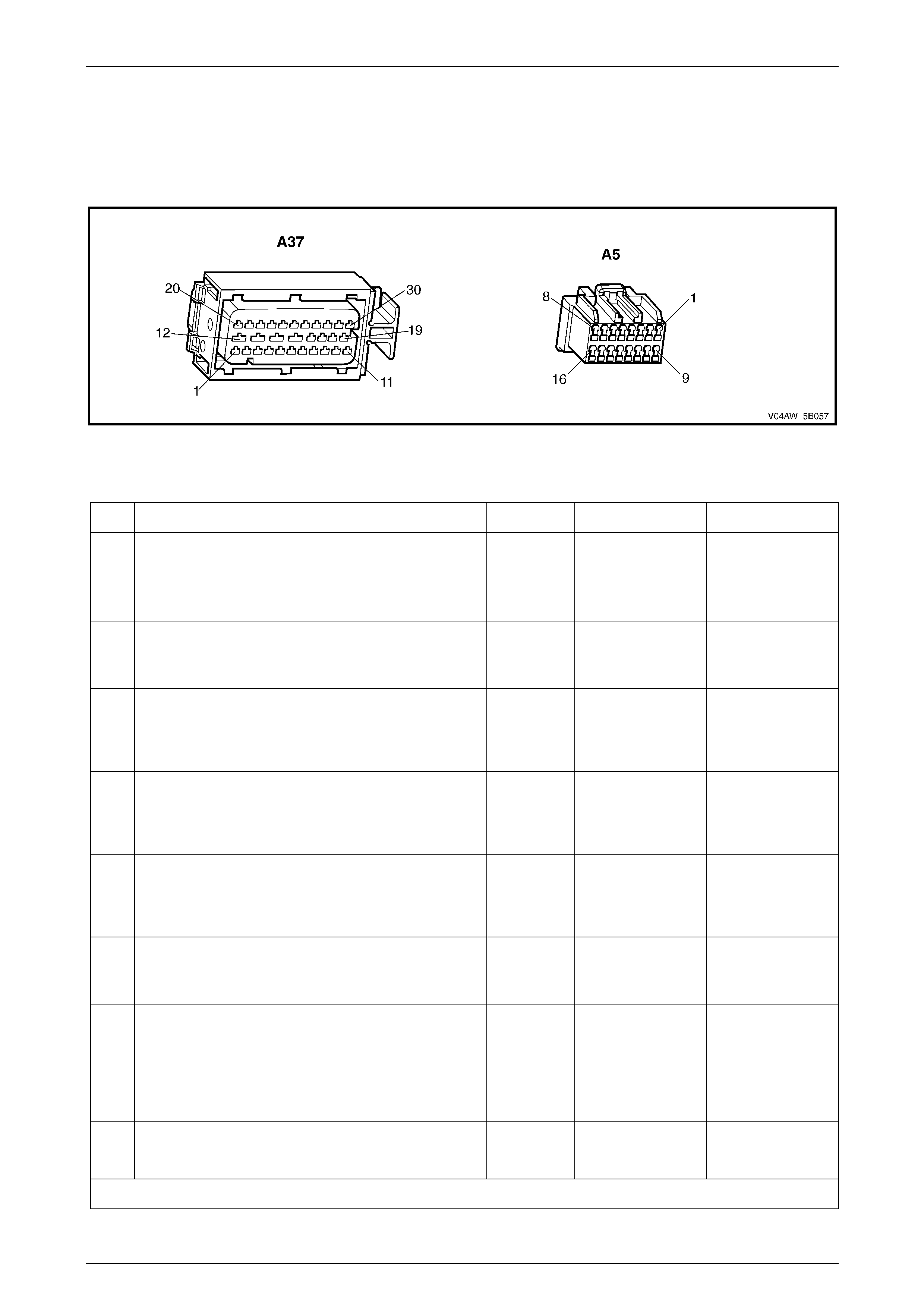
AW D ABS-TCS Page 5B–113
Page 5B–113
Additional information
• Refer to 4.2 DTCs for information on the conditions for clearing DTCs.
• For intermittent fault conditions, refer to 6 Intermittent Conditions.
• Refer to Figure 5B – 72 for ECU connector illustration.
Figure 5B – 72
DTC U1016 Diagnostic Table
Step Action Value(s) Yes No
1 Was the Serial Data Communication Preliminary
Diagnostic Table performed? – Go to Step 2 Refer to
8.1 Serial Data
Communication
Preliminary
Diagnostic Table.
2 Test the Class 2 serial data circuit 1045 for an open
circuit fault condition.
Was any fault found and rectified? – Go to Step 7 Go to Step 3
3 Inspect for poor wiring connection at the PCM wiring
connector. Refer to Section 12P Wiring Diagrams for
information on testing wiring circuits.
Was any fault found and rectified?
–
Go to Step 7 Go to Step 4
4 Inspect for poor wiring connection at the PIM wiring
connector. Refer to Section 12P Wiring Diagrams for
information on testing wiring circuits.
Was any fault found and rectified?
–
Go to Step 7 Go to Step 5
5 Inspect for poor connections at the ECU wiring
connector. Refer to Section 12P Wiring Diagrams for
information on testing wiring circuits.
Was any fault found and rectified?
–
Go to Step 7 Go to Step 6
6 Replace the ECU. Refer to 9.3 ECU /hydraulic
modulator.
Was the repair completed? – Go to Step 7 –
7 1 Using Tech 2, clear the DTCs.
2 Switch off the ignition for 10 seconds.
3 Operate the vehicle within the conditions for
running DTC U1016.
Did DTC U1016 fail this ignition?
–
Go to Step 2 Go to Step 8
8 Using Tech 2, select the DTC display function.
Are there any DTC displayed? – Go to the
appropriate DTC
Table. System OK
When all diagnosis and repairs are completed, check the system for correct operation.

AW D ABS-TCS Page 5B–114
Page 5B–114
8.4 DTC U1300 or U1301 Class 2
Communication Data Link Input Too Low
or Too High
Circuit Descri ption
The Electronic Control Unit (ECU) communicates information with the various electronic control modules integrated into
the vehicle through the Serial Data Bus
The ECU and the Powertrain Control Module (PCM) transmit and receive data using Class 2 Serial Data protocol while
the BCM and other vehicle control modules use the Universal Asynchronous Receive and Transmit (UART) protocol.
As the Class 2 Serial Data protocol is not compatible with the UART protocol, a Powertrain Interface Module (PIM) is
integrated to the data link communication system.
If the ECU detects that the Class 2 serial data circuit 1045 is either shorted to ground or shorted to voltage during an
ignition cycle, either DTC U1300 or DTC U1301 sets.
Figure 5B – 73
Diagnostic Aids
Conditions for Running DTC U1300 or U1301
• The ignition is switched on.
Conditions for Setting DTC U1300 or U1301
• If the ECU detects that the Class 2 serial data circuit 1045 is shorted to ground DTC U1300 sets.
• If the ECU detects that the Class 2 serial data circuit 1045 is shorted to voltage DTC U1301 sets.
Action Taken when DTC U1300 or U1301 sets
• The ECU uses default values for all parameters on the Class 2 serial data circuit.
• The ABS wa rning lam p , the ABS warning icon and the trac-off icon activates.
• The brake failure lamp activates.

AW D ABS-TCS Page 5B–115
Page 5B–115
Additional information
• Refer to 4.2 DTCs for information on the conditions for clearing DTCs.
• For intermittent fault conditions, refer to 6 Intermittent Conditions.
• Refer to Figure 5B – 74 for ECU connector illustration.
Figure 5B – 74
DTC U1300 or U1301 Diagnostic Table
Step Action Value(s) Yes No
1 Was the Serial Data Communication Preliminary
Diagnostic Table performed? – Go to Step 2 Refer to
8.1 Serial Data
Communication
Preliminary
Diagnostic Table.
2 Test the Class 2 serial data circuit 1045 for a short to
ground or a short to voltage fault condition.
Was any fault found and rectified? – Go to Step 6 Go to Step 3
3 Inspect for poor wiring connection at the PIM wiring
connector. Refer to Section 12P Wiring Diagrams for
information on testing wiring circuits.
Was any fault found and rectified?
–
Go to Step 6 Go to Step 4
4 Inspect for poor connections at the ECU wiring
connector. Refer to Section 12P Wiring Diagrams for
information on testing wiring circuits.
Was any fault found and rectified?
–
Go to Step 6 Go to Step 5
5 Replace the ECU. Refer to 9.3 ECU /hydraulic
modulator.
Was the repair completed? – Go to Step 6 –
6 1 Using Tech 2, clear the DTCs.
2 Switch off the ignition for 10 seconds.
3 Operate the vehicle within the conditions for
running DTC U1300 or U1301.
Did DTC U1300 or U1301 fail this ignition?
–
Go to Step 2 Go to Step 7
7 Using Tech 2, select the DTC display function.
Are there any DTC displayed? – Go to the
appropriate DTC
Table. System OK
When all diagnosis and repairs are completed, check the system for correct operation.

AW D ABS-TCS Page 5B–116
Page 5B–116
9 Service Operations
9.1 Safety and Precautionary Measures
The following safety and precautionary
measures must be followed when servicing
and diagnosing the ABS-TCS Braking System.
Otherwise, personal injury and/or improper
braking system operation may occur:
1 If any ABS-TCS component is serviced, the complete ABS-TCS must be checked. Refer to 5.2 AWD ABS-TCS
Main Diagnostic Table.
2 Certain components in the ABS-TCS are not intended to be serviced individually and must be replaced as an
assembly. Attempting to service components, such as the solenoid valves or pump motor in the hydraulic
modulator may result in improper system operation and/or personal injury. Only components with approved
removal and reinstallation procedures described in this Section should be serviced.
3 If the brake hydraulic system is serviced, the brake system must be bled and all brake hydraulic fittings must be
tested for leakage. Refer to Section 5A Service and Parking Brake System.
4 Whenever welding with an electric welding equipment, disconnect the wiring harness connector from the ECU .
Refer to 9.3 ECU /hydraulic modulator Assembly.
5 Never disconnect or reconnect the ECU wiring harness connector when the battery is connected or the ignition is
switched ON.
6 Do not touch the ECU connector pins or soldered components on the ECU circuit board to prevent possible
Electrostatic Discharge damage.
7 When pressure washing engines, do not direct the cleaning nozzle at ABS-TCS components.
8 To avoid wiring connector terminal damage, always use suitable wiring harness test leads (such as those in Tool
No, J39700) when carrying test operation on the ECU or sensor wiring connector.
9 As the ABS-TCS components are extremely sensitive to Electro-Magnetic Interference (EMI). Ensure that the
ABS-TCS wiring harness is routed correctly and securely fitted on their mounting clips when performing service
procedures.
10 Due to the sensitive nature of the ABS-TCS circuitry, specific ABS-TCS wiring repair procedures have been
developed. These procedures and instructions are detailed in Section 12P Wiring Diagrams and are the only
recommended and approved wiring repair methods.
11 Ensure that the brake lines and the wheel speed sensor wiring harness connections are assigned correctly.
12 The ECU is calibrated to use tyres of a known rolling radius and pulse rings with a specific number of teeth. The
number of teeth on the pulse rings correspond directly to tyre size. If any of the tyres fitted to the vehicle are larger
or smaller than specified, the ECU will receive false wheel speed signals that could result in personal injury and/or
improper ABS-TCS operation.
13 Do not allow the suspension components to hang by the wheel speed sensor cables.
14 Ensure that all wiring harness connectors are seated correctly.
15 Never disconnect the battery from the vehicle electrical system while the engine is running.
16 Always disconnect the battery from the vehicle electrical system before charging.
17 Do not use a fast charger for starting the vehicle.
18 Ensure that the battery cable terminals are secure.
19 The ECU and the hydraulic modulator must never be disassembled. Repair of either of these two units is by
replacement only. Apart from the brake line connections and the six screws securing the control module to the
hydraulic modulator, no screws at the hydraulic modulator may be loosened. Once any screw is loosened, brake
fluid leakage from the hydraulic modulator may occur.

AW D ABS-TCS Page 5B–117
Page 5B–117
20 Replacement hydraulic modulator assemblies are pre-filled with brake fluid. To avoid unnecessary fluid spillage,
do not remove the sealing plugs from hydraulic modulator ports until the brake fittings are ready for fitment.
21 Once a replacement hydraulic modulator has been fitted, the sealing plugs must be fitted to the original modulator
to prevent entry of dirt.
22 To prevent entry of dirt into the hydraulic modulator ports, ensure that the hydraulic modulator is clean before
disconnecting or reconnecting its brake pipe fittings.
23 Remove the ECU from its packaging only when it is ready to be fitted to the hydraulic modulator.
24 While it is possible to replace the control module assembly without removing the hydraulic modulator from the
vehicle, the ECU spring plate will not seat correctly if not fitted in a horizontal position. Therefore, to ensure the
correct installation of the replacement control module, the ECU /hydraulic modulator assembly must be removed
from the vehicle, prior to disassembly. Refer to 9.3 ECU /hydraulic modulator Assembly.
25 Before installing a new ECU or hydraulic modulator, ensure that the correct type is fitted. Always refer to the latest
spare parts information.
26 Even the slightest trace of mineral oil leads to failure of the brake system. If mineral oil is found in the brake
system or there is a suspicion of mineral oil being in the brake system, the complete brake system must be
thoroughly flushed with the correct type of brake fluid. In addition, the brake master cylinder must be replaced.
27 Do not allow brake fluid to come in contact with the vehicle paintwork as the brake fluid causes paint damage.
28 Store the brake fluid in well-sealed containers as the brake fluid absorbs moisture from the air thus reducing its
boiling point. If the brakes are subjected to a very severe loading, this can lead to vapour-bubble formation in the
brake system which may lead to brake failure.
In addition, the brake fluid absorbs moisture from the atmosphere as it is operated in the vehicle. Therefore, the
brake fluid must be replaced at the time or distance intervals as specified in Section 0B, Lubrication And Service.
29 Only use the specified brake fluid.
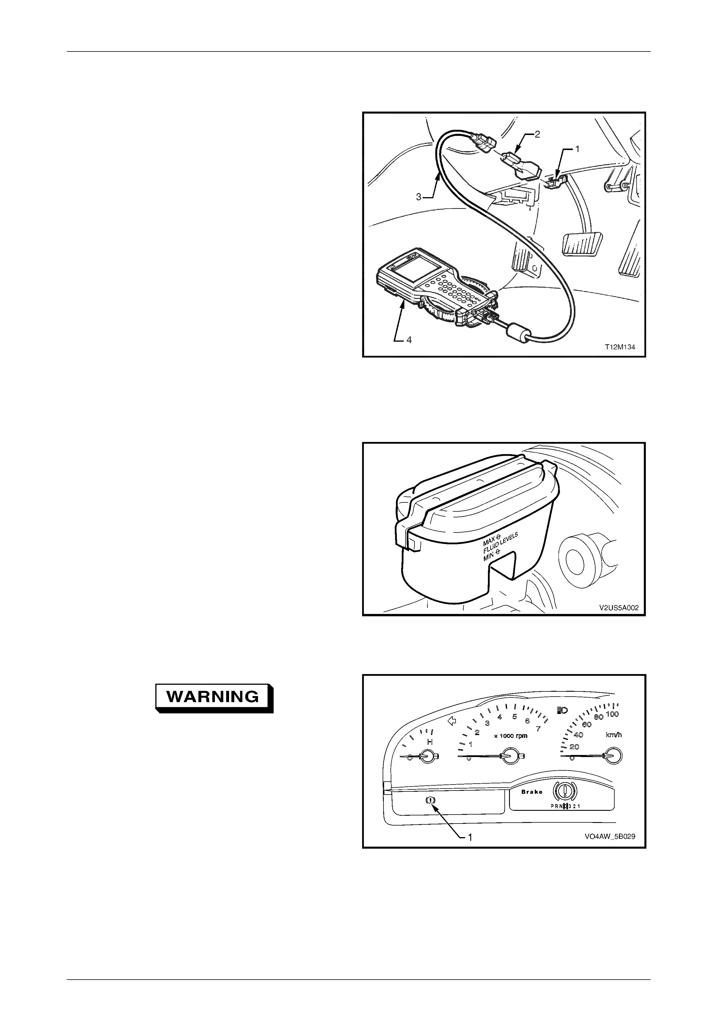
AW D ABS-TCS Page 5B–118
Page 5B–118
9.2 ABS-TCS Brake Bleeding Procedure
NOTE
The conventional brake system bleeding
procedure must be completed before performing
the ABS-TCS brake bleeding procedure. Refer
to Section 5A Service and Parking Brake
System.
1 Using the appropriate Tech 2 adapter (2) connected to
the DLC cable (3), connect Tech 2 to the DLC (1).
2 Start the engine and allow to run at idle speed.
3 Perform the instructions listed in the Tech 2 Brake
Bleed Procedure. Refer to Section 0C, Tech 2 for
information on the use of Tech 2.
NOTE
Ensure that the brake fluid level in the brake
master cylinder doesn't drop below the minimum
level during the duration of this procedure.
4 Turn the ignition switch off.
5 Disconnect Tech 2 from the DLC.
Figure 5B – 75
6 Fill the brake master cylinder reservoir to the
maximum fill level with the specified brake fluid.
7 Perform another conventional braking system brake
bleeding operation. Refer to Section 5A Service and
Parking Brake System.
8 With the ignition switched off, depress the brake pedal
three to five times to deplete the brake booster
vacuum reserve.
9 Slowly depress the brake pedal. If the brake pedal
feels spongy, repeat the ABS-TCS brake bleeding
operation.
10 If the brake pedal still feels spongy after repeating the
ABS-TCS bleeding operation, inspect the brake
system for external or internal leakage. Refer to
Section 5A Service and Parking Brake System.
Figure 5B – 76
If the brake fail lamp remains illuminated
after a service procedure, do not drive the
vehicle until the fault is diagnosed and
repaired.
11 Turn the ignition switch on with the engine not running
and the park brake not applied. If the park brake /
brake fail lamp (1) remains illuminated, diagnose and
repair the fault condition. Refer to Section 5A Service
and Parking Brake System.
12 Road test the vehicle to allow ABS-TCS self test
initialisation to occur. If the brake pedal feels spongy,
repeat the ABS-TCS brake bleed operation until a firm
brake pedal feel is obtained.
13 Check the ABS-TCS operation. Re fer to 5.2 AWD
ABS-TCS Main Diagnostic Table.
Figure 5B – 77
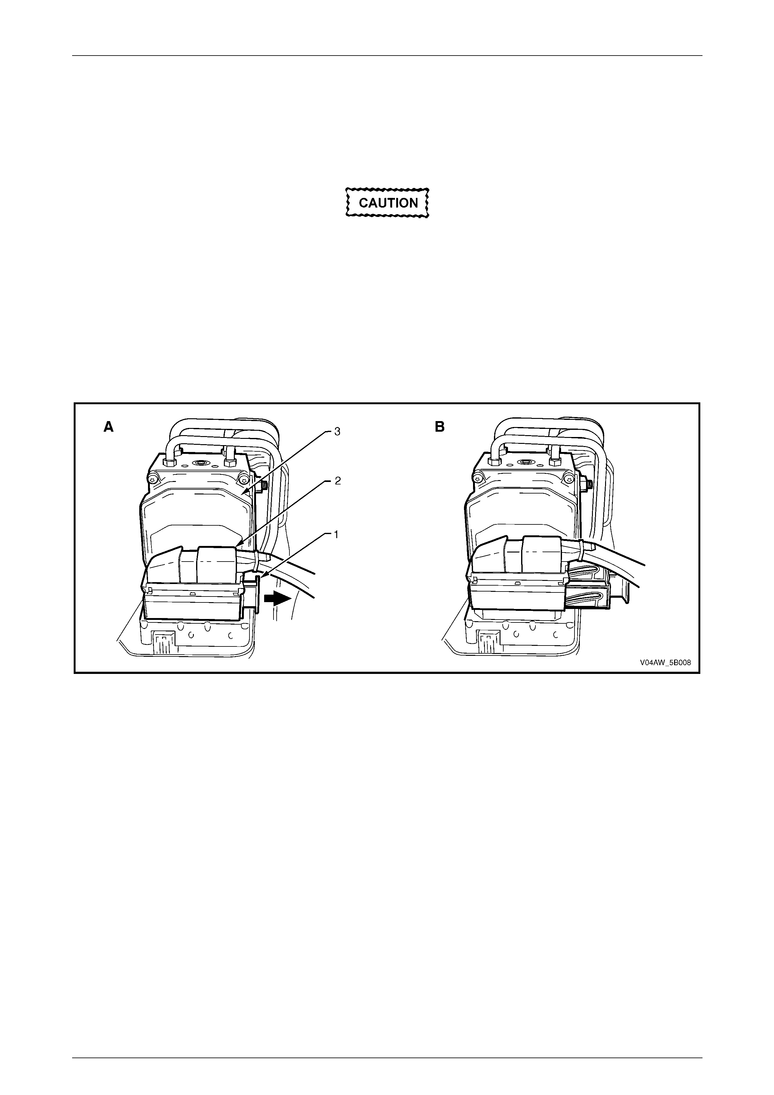
AW D ABS-TCS Page 5B–119
Page 5B–119
9.3 Electronic Control Unit (ECU) /
Hydraulic Modulator Assembly
Remove
Disconnection of the battery affects
certain vehicle electronic systems. Refer to
Section 00, Cautions and Notes before
disconnecting the battery.
1 Disconnect the battery negative terminal.
2 Retract the ECU wiring connector release bar (1, view A) to disconnect the ECU wiring connector (2) from the ECU
(3). The ECU wiring harness connector will automatically lift-out when the release bar is retracted (view B). Refer
to Figure 5B–78.
Figure 5B – 78
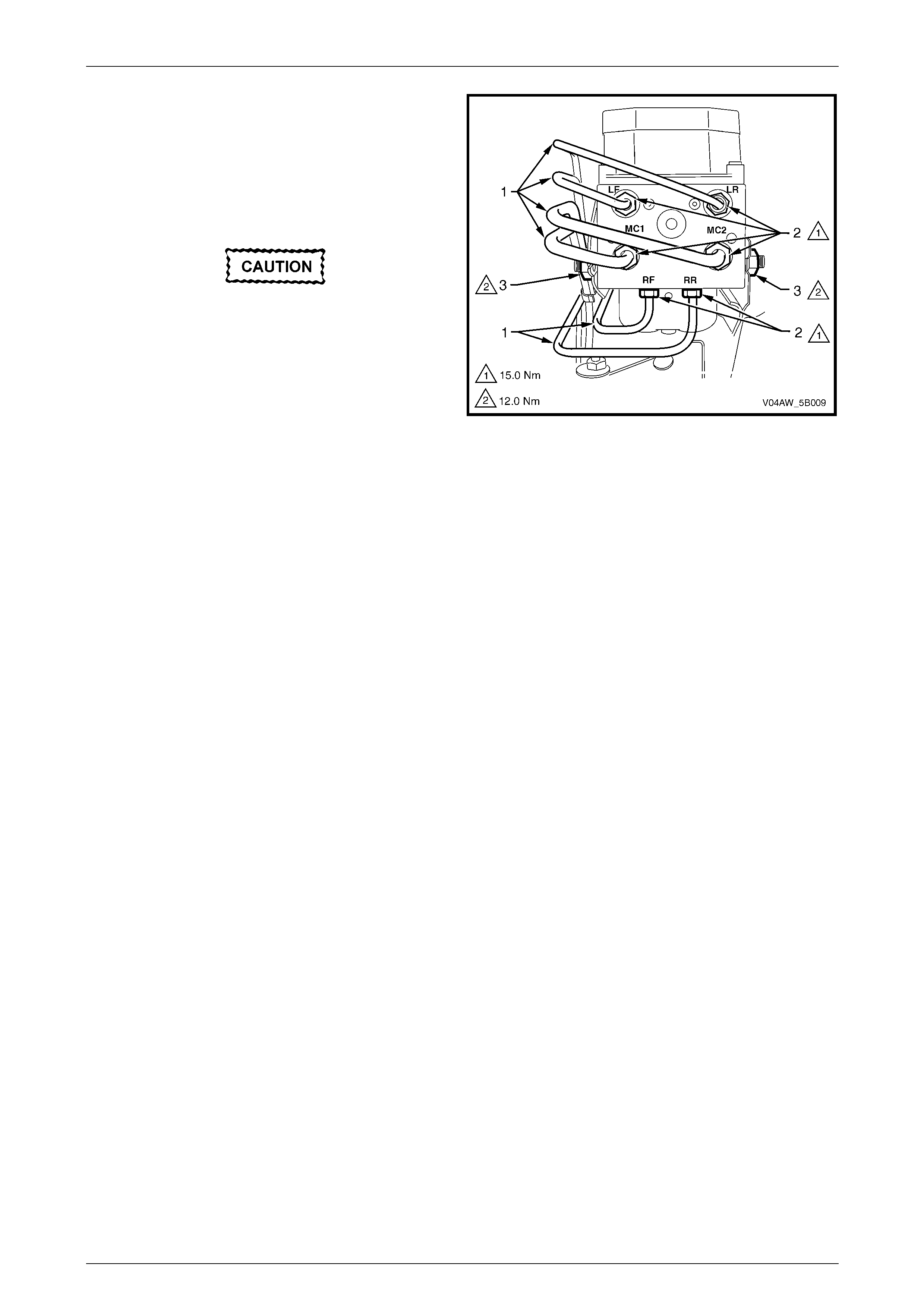
AW D ABS-TCS Page 5B–120
Page 5B–120
3 Note the brake pipe (1) fitting connections to the
hydraulic modulator to aid in reassembly.
4 Place shop rags around and beneath the hydraulic
modulator.
5 Loosen and disconnect the hydraulic modulator brake
pipe fittings (2).
Immediately seal off the brake pipes and the
hydraulic modulator with dummy plugs to
prevent the loss of brake fluid and entry of
dirt.
5 Carefully reposition the pipes away from the hydraulic
modulator ports. Do not to damage or kink the brake
pipes in any way.
6 Remove the nuts (3) securing the ECU/hydraulic
modulator assembly to the mounting bracket.
7 Remove the ECU/hydraulic modulator assembly from
the vehicle.
Figure 5B – 79
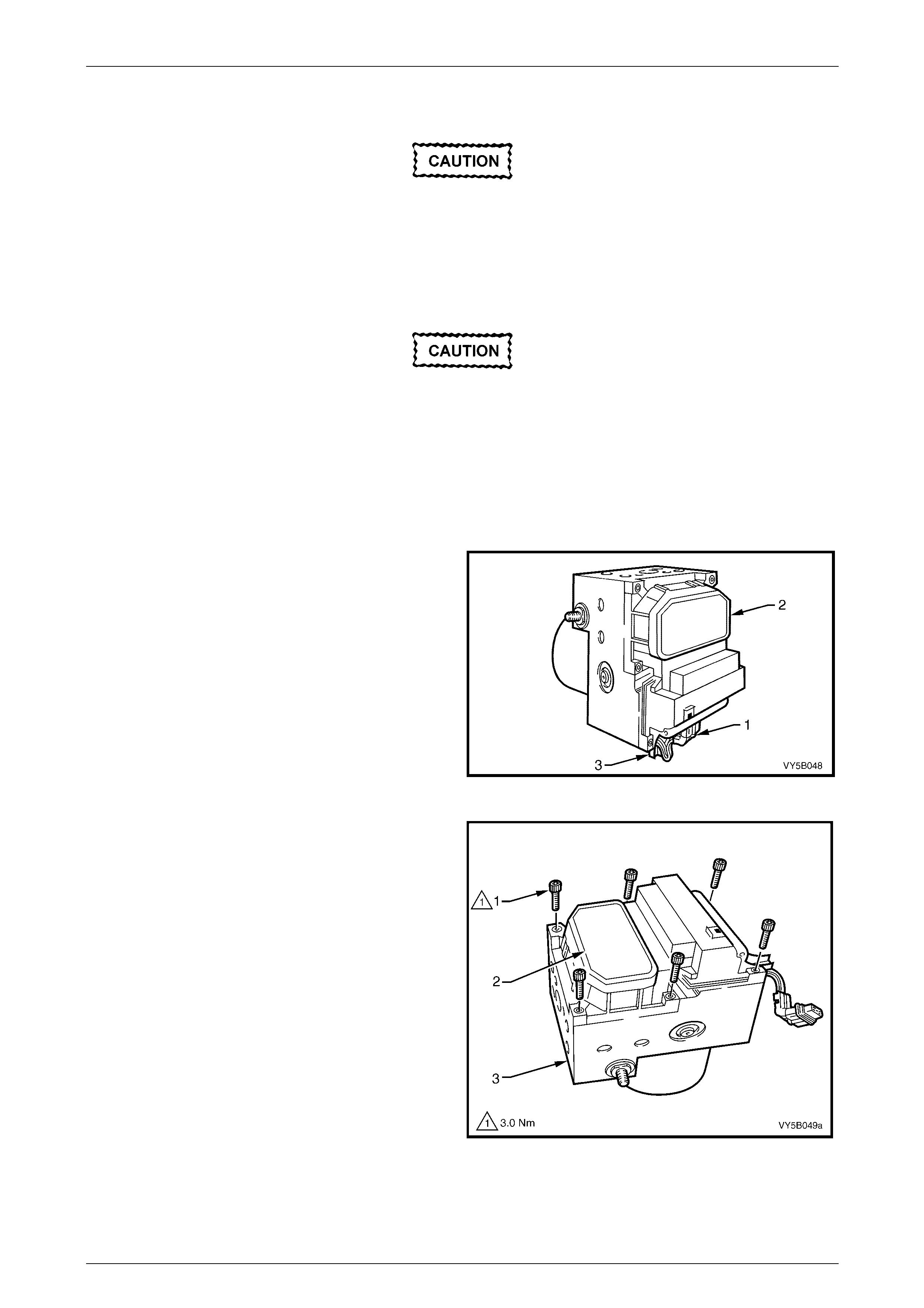
AW D ABS-TCS Page 5B–121
Page 5B–121
Disassemble
If the ECU or the hydraulic modulator is to be
replaced under manufacturer's warranty, do
not disassemble the ECU/hydraulic modulator
assembly. If either the ECU or the hydraulic
modulator is faulty, replace the complete
ECU/hydraulic modulator assembly.
While it is possible to replace the ECU
without removing the hydraulic modulator
from the vehicle, the ECU spring plate w ill not
seat correctly if not fitted in a horizontal
position. Therefore, to ensure the correct
installation of the replacement ECU, the
ECU/hydraulic modulator assembly must be
removed from the vehicle, prior to
disassembly.
1 Disconnect the hydraulic modulator motor wiring
harness connector (1) from the ECU (2).
2 Remove the hydraulic modulator motor wiring from its
retainer (3).
Figure 5B – 80
3 Support the ECU/hydraulic modulator assembly in a
horizontal position with the ECU (2) on top.
4 Remove the screws (1) securing the ECU to the
hydraulic modulator (3).
Figure 5B – 81
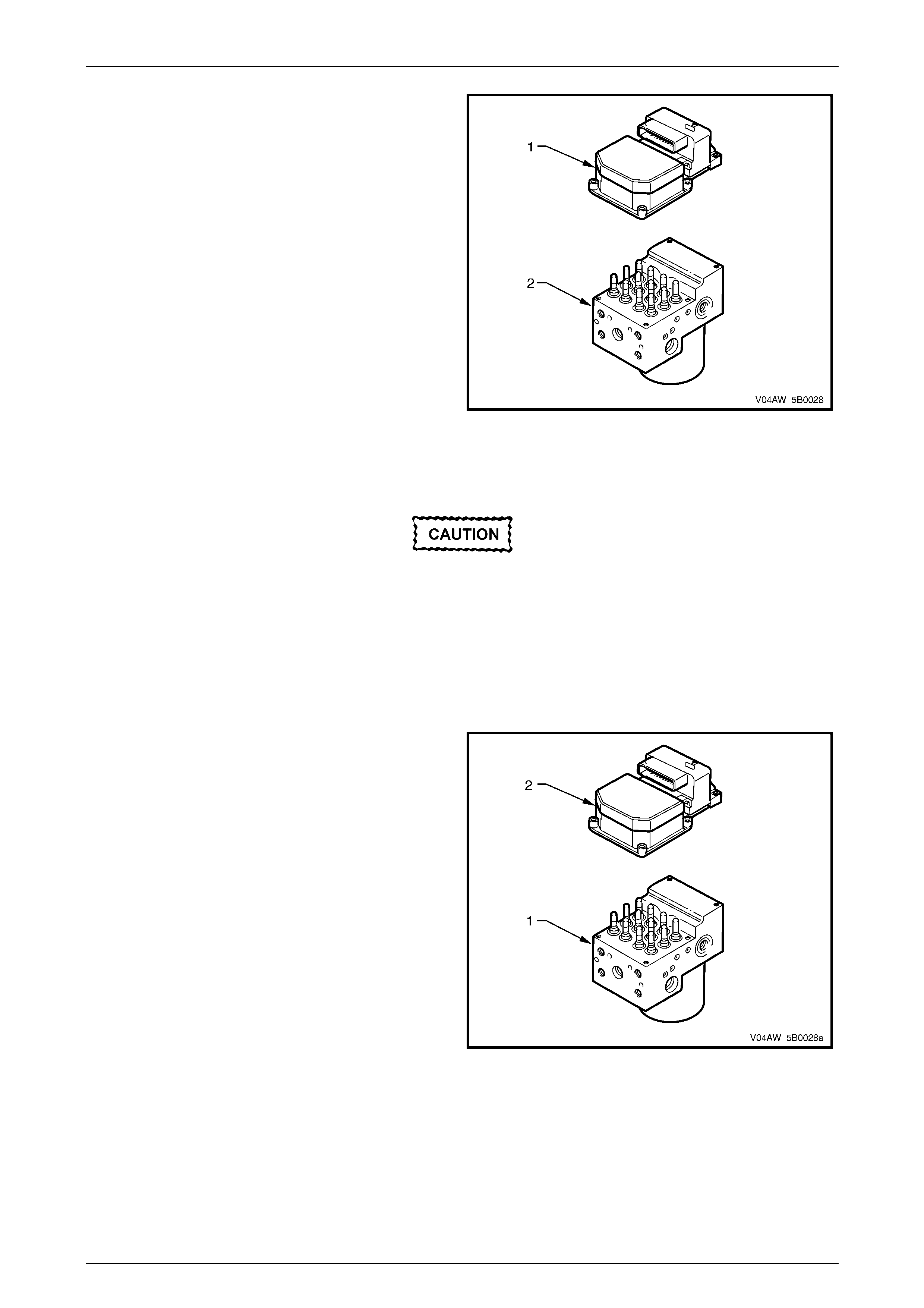
AW D ABS-TCS Page 5B–122
Page 5B–122
5 Lift the ECU (1) upwards and remove from the
hydraulic modulator (2).
6 Cover the hydraulic modulator valve body to prevent
damage or entry of dirt.
Figure 5B – 82
Inspect
When cleaning the ECU to hydraulic
modulator mating surfaces, the use of
chemical solvents is not permitted.
Inspect the ECU to hydraulic modulator mating surfaces and seal. The seal is not available as a spare part and the
mating surfaces cannot be mechanically reworked. Therefore, if the ECU to hydraulic modulator seal or its mating
surfaces are damaged, the complete ECU/hydraulic modulator assembly must be replaced.
Reassemble
1 Ensure that the ECU to hydraulic modulator mating
surface is clean.
2 Position the hydraulic modulator (1) so that the
solenoid valves face upwards.
3 Remove the new control module (2) from its protective
packaging
4 Install the ECU into the hydraulic modulator.
Figure 5B – 83
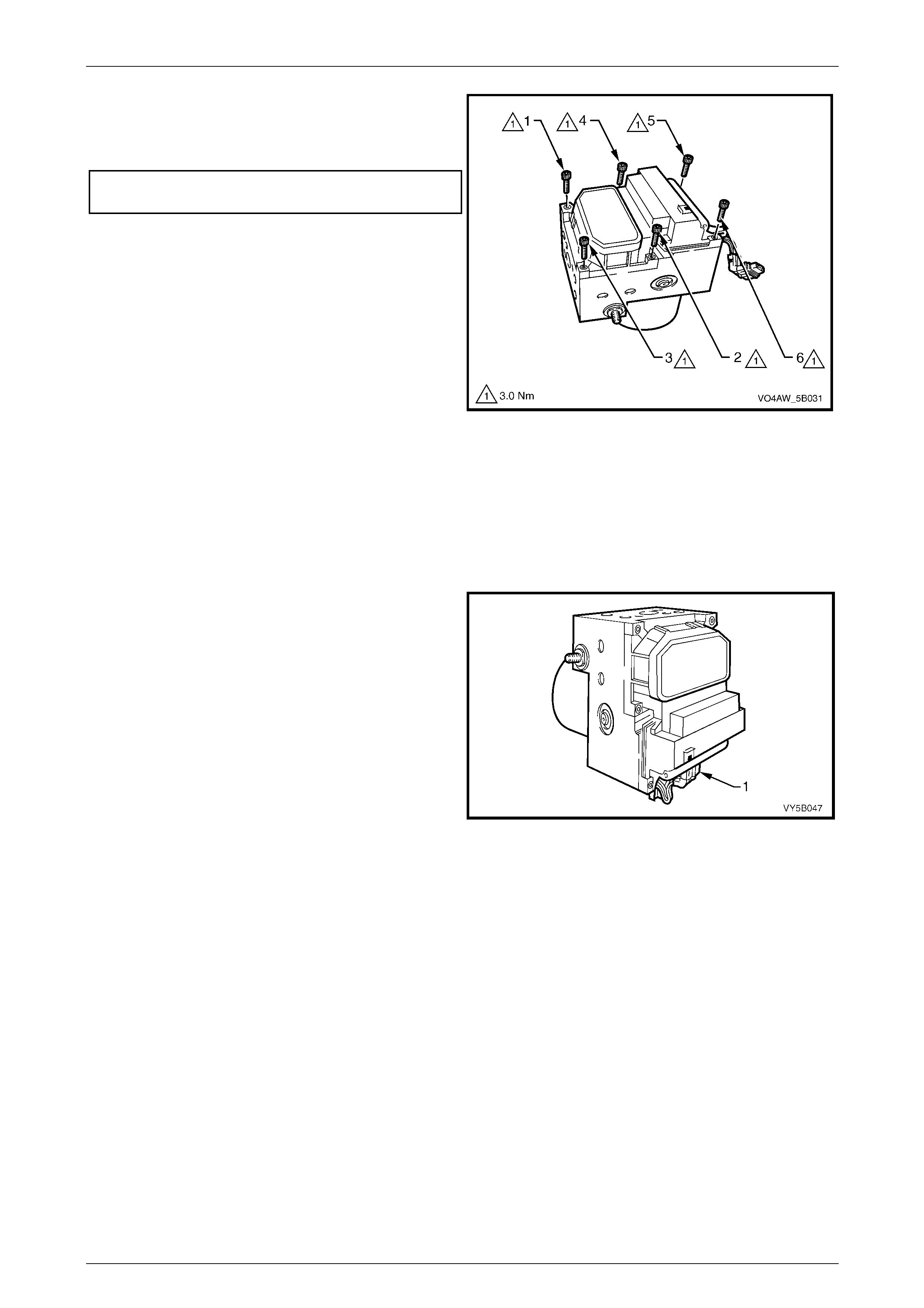
AW D ABS-TCS Page 5B–123
Page 5B–123
5 Install the screws retaining the ECU to the hydraulic
modulator. Tighten the screws in the specified
sequence (1 – 6) and to the correct torque
specification.
ECU retaining screw
torque specification.............................................3.0 Nm
6 Ensure that there is no gap between ECU and the
hydraulic modulator mating surface.
7 Connect the hydraulic modulator motor wiring harness
connector and press the motor wiring harness into its
retainer.
8 Reinstall the hydraulic ECU/hydraulic modulator
assembly into the vehicle. Refer to 9.3, ECU/hydraulic
modulator Assembly.
9 Check ABS-TCS operation. Refer to 5.2 AWD ABS-
TCS Main Diagnostic Table.
Figure 5B – 84
Reinstall
Reinstallation of the ECU/hydraulic modulator assembly is the reverse of removal procedures except for the following:
1 Ensure that the mounting bracket area is clean and free from brake fluid contamination.
2 Ensure that the bottom hydraulic modulator rubber insulator is correctly fitted.
3 Ensure the hydraulic modulator motor wiring harness
connector (1) is properly connected to the ECU.
Figure 5B – 85
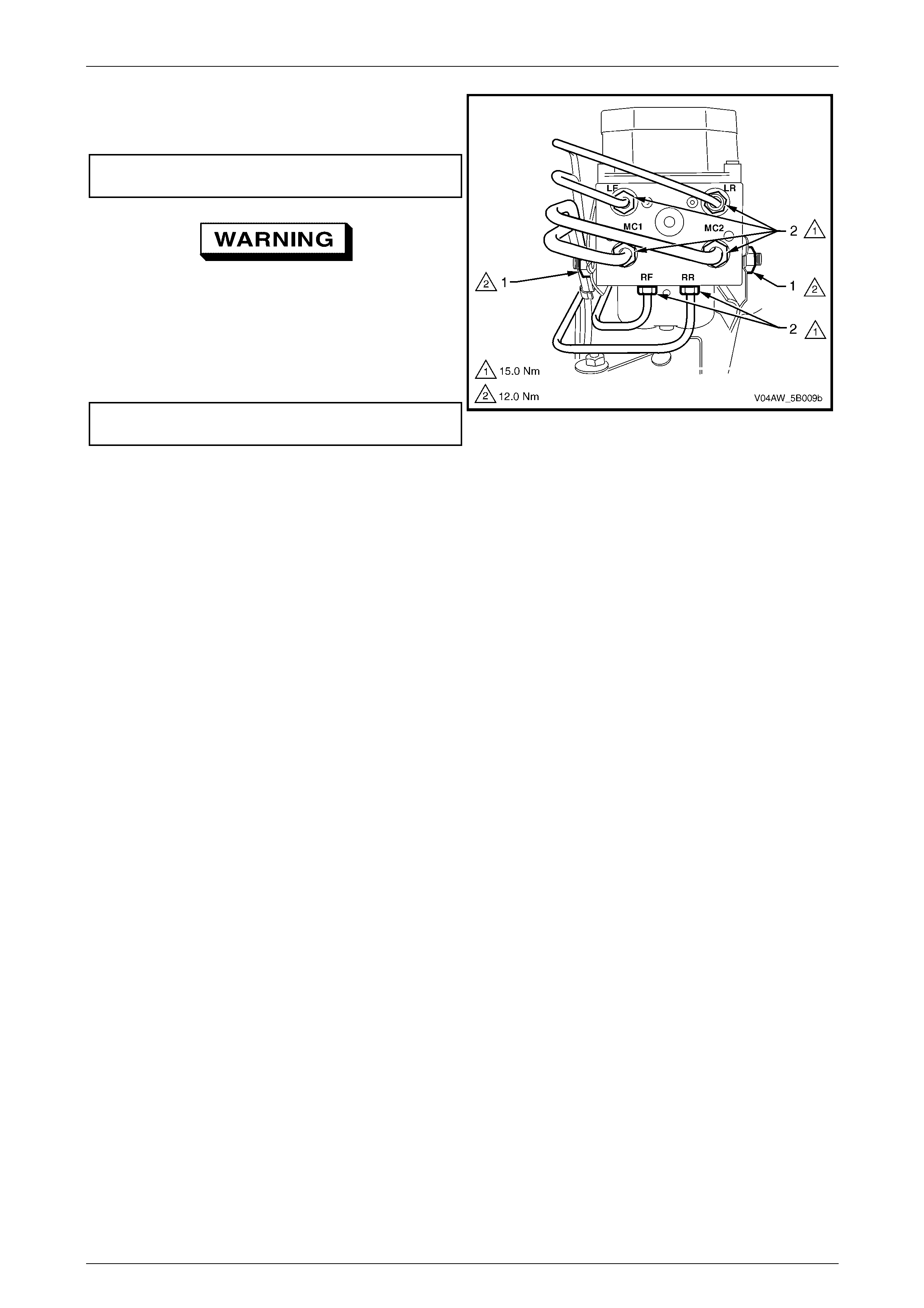
AW D ABS-TCS Page 5B–124
Page 5B–124
4 Tighten the nuts (1) securing the ECU/hydraulic
modulator assembly to the correct torque
specification.
ECU /hydraulic modulator assembly securing nut
torque specification...........................................12.0 Nm
If the brake pipe fittings are incorrectly fitted,
wheel lock-up will occur and personal injury
may result.
5 Install the brake pipe fittings (2) to the correct
hydraulic modulator ports and tighten to the correct
torque specification.
Brake pipe fitting
torque specification...........................................15.0 Nm
6 Bleed the ABS-TCS hydraulic circuit. Refer to
9.2, ABS-TCS Brake Bleeding Procedure.
7 Check the ABS-TCS operation. Refer to
5.2 AWD ABS-TCS Main Diagnostic Table.
Figure 5B – 86
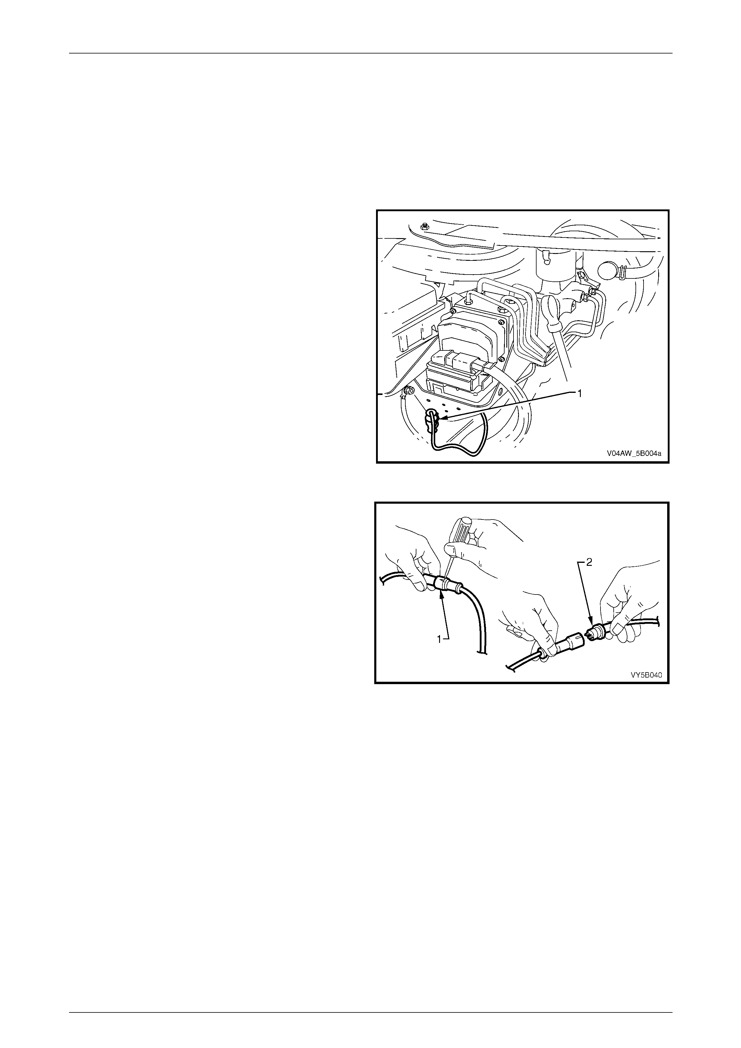
AW D ABS-TCS Page 5B–125
Page 5B–125
9.4 Front Right Wheel Speed Sensor
Remove
1 Raise the front of the vehicle and support on safety stands, Refer to Section 0A General Information for location of
the jacking points.
2 Remove the front right wheel. Refer to Section 10 Wheels and Tyres.
3 Remove the front right wheel speed sensor wiring
connector (1) from its mounting clip.
Figure 5B – 87
4 Using a small screwdriver, disconnect the front right
wheel speed sensor wiring connector (1) from the
main wiring harness connector.
5 Inspect the connector O-ring (2) and replace if
required.
Figure 5B – 88
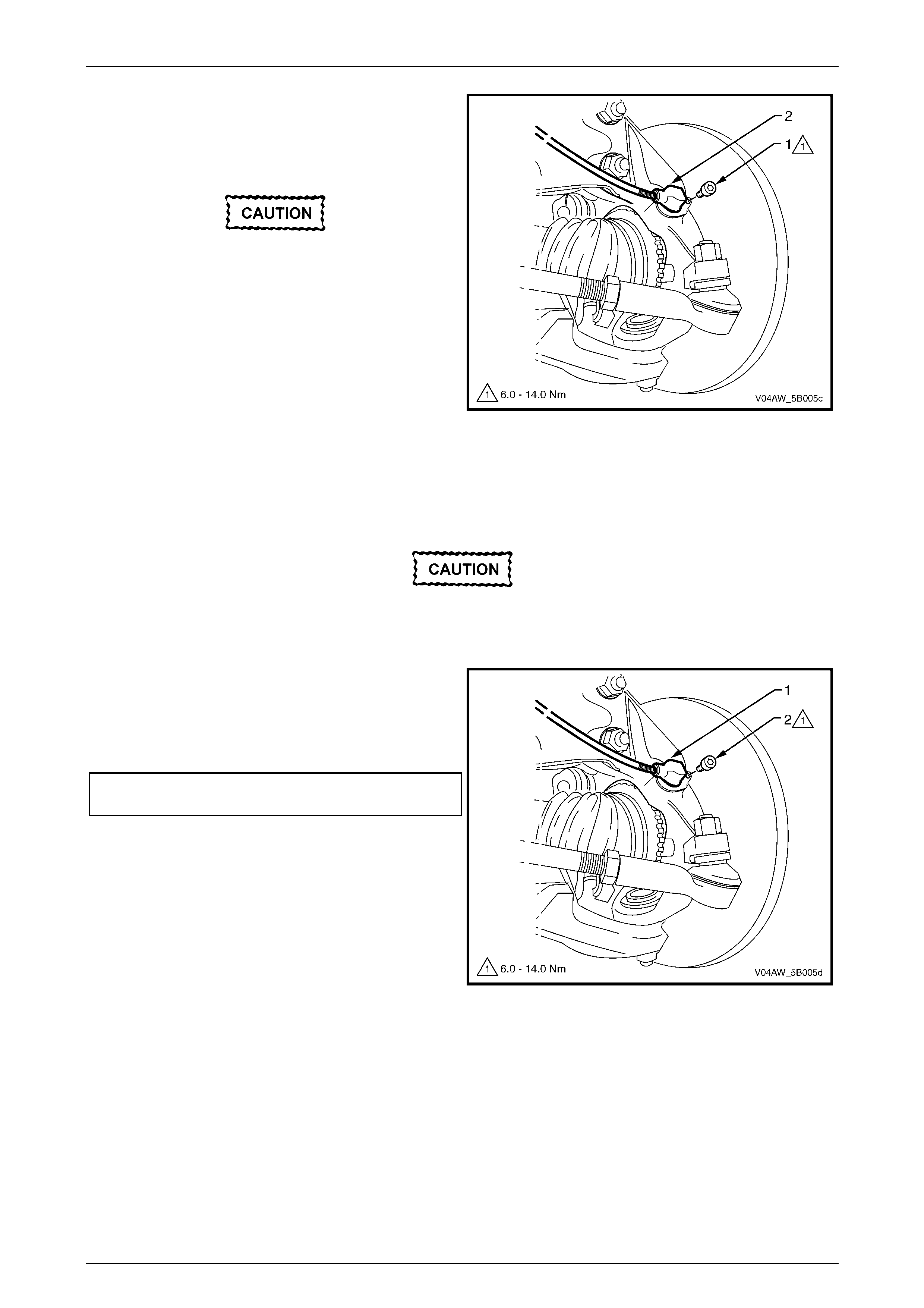
AW D ABS-TCS Page 5B–126
Page 5B–126
6 Remove the screw (1) attaching the front right wheel
speed sensor (2) to the steering knuckle.
7 With a twisting motion, withdraw the front right wheel
speed sensor from the steering knuckle bore.
Do not use a screwdriver or other device to
prise the wheel speed sensor out. Otherwise,
damage to the wheel speed sensor may
occur.
8 Note the front right wheel speed sensor wiring
harness routing then remove the sensor assembly
from the vehicle.
9 Clean the wheel speed sensor to steering knuckle
mating surface. Figure 5B – 89
Reinstall
Reinstallation of the front right wheel speed sensor is the reverse of the removal procedure noting the following.
A replacement wheel sensor must only be
taken out its packaging immediately before
installing on the vehicle.
1 With a twisting motion, install the front right wheel
speed sensor (1) to the steering knuckle bore.
2 Install the screw (2) attaching the front right wh eel
speed sensor to the steering knuckle and tighten to
the correct torque specification.
Front right wheel speed sensor
attaching screw........................................6.0 – 14.0 Nm
3 Check the ABS-TCS operation. Refer to
5.2 AWD ABS-TCS Main Diagnostic Table.
Figure 5B – 90
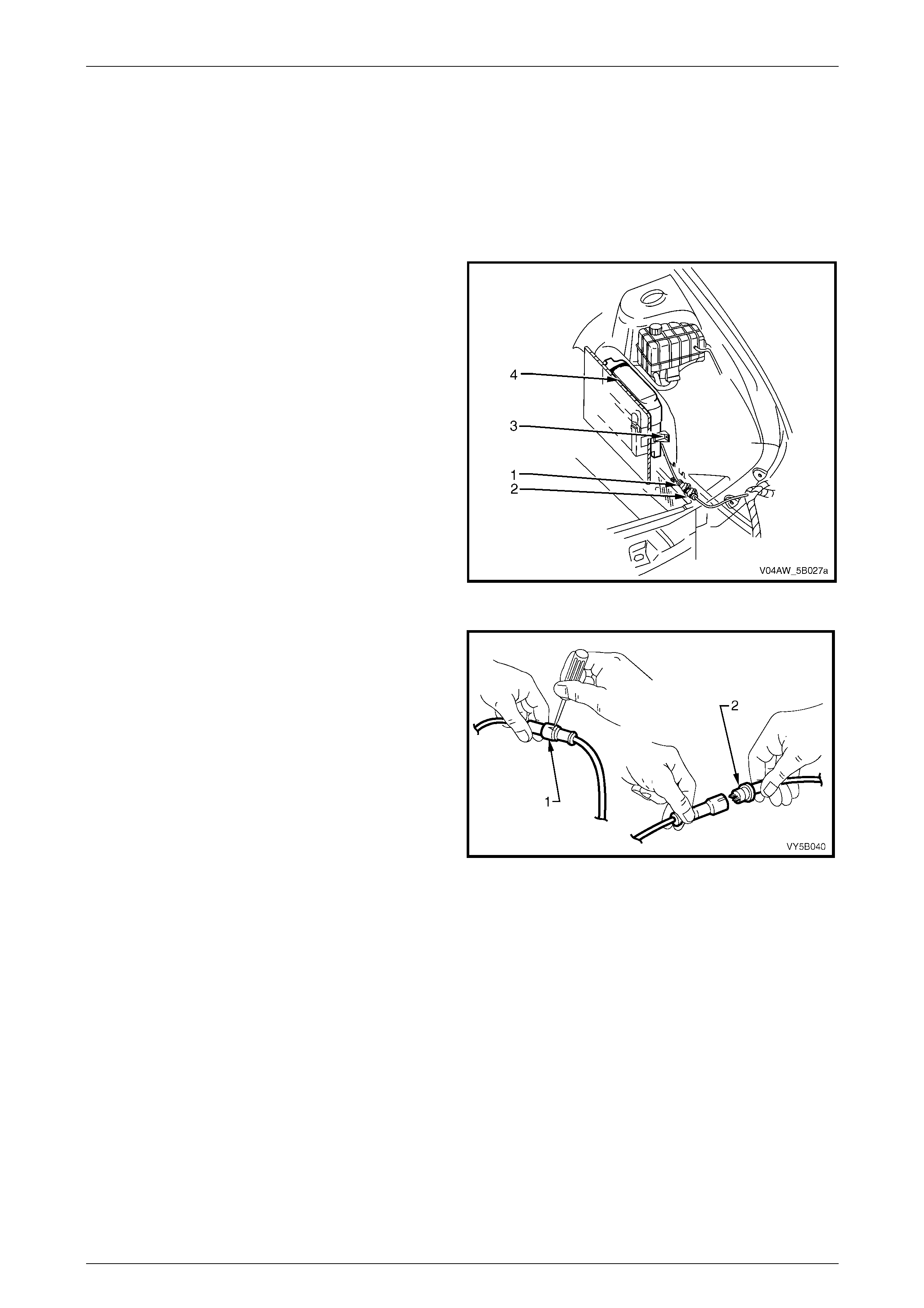
AW D ABS-TCS Page 5B–127
Page 5B–127
9.5 Front Left Wheel Speed Sensor
Remove
1 Raise the front of the vehicle and support on safety stands, Refer to Section 0A General Information for location of
the jacking points.
2 Remove front left wheel. Refer to Section 10 Wheels and Tyres.
3 Remove the front left wheel speed sensor wiring
connector (1) from its mounting clip (2).
4 Remove screws (3), in two places, attaching the
Powertrain Control Module (PCM) to allow the front
left wheel speed sensor connector to pass through the
gap between the PCM (4) and the vehicle body. Refer
to Section 6C3 Engine Management for information
on the removal of the PCM attaching screws.
Figure 5B – 91
5 Using a small screwdriver, disconnect the front left
wheel speed sensor wiring connector (1) from the
main wiring harness connector.
6 Inspect the connector O-ring (2) and replace if
required.
Figure 5B – 92
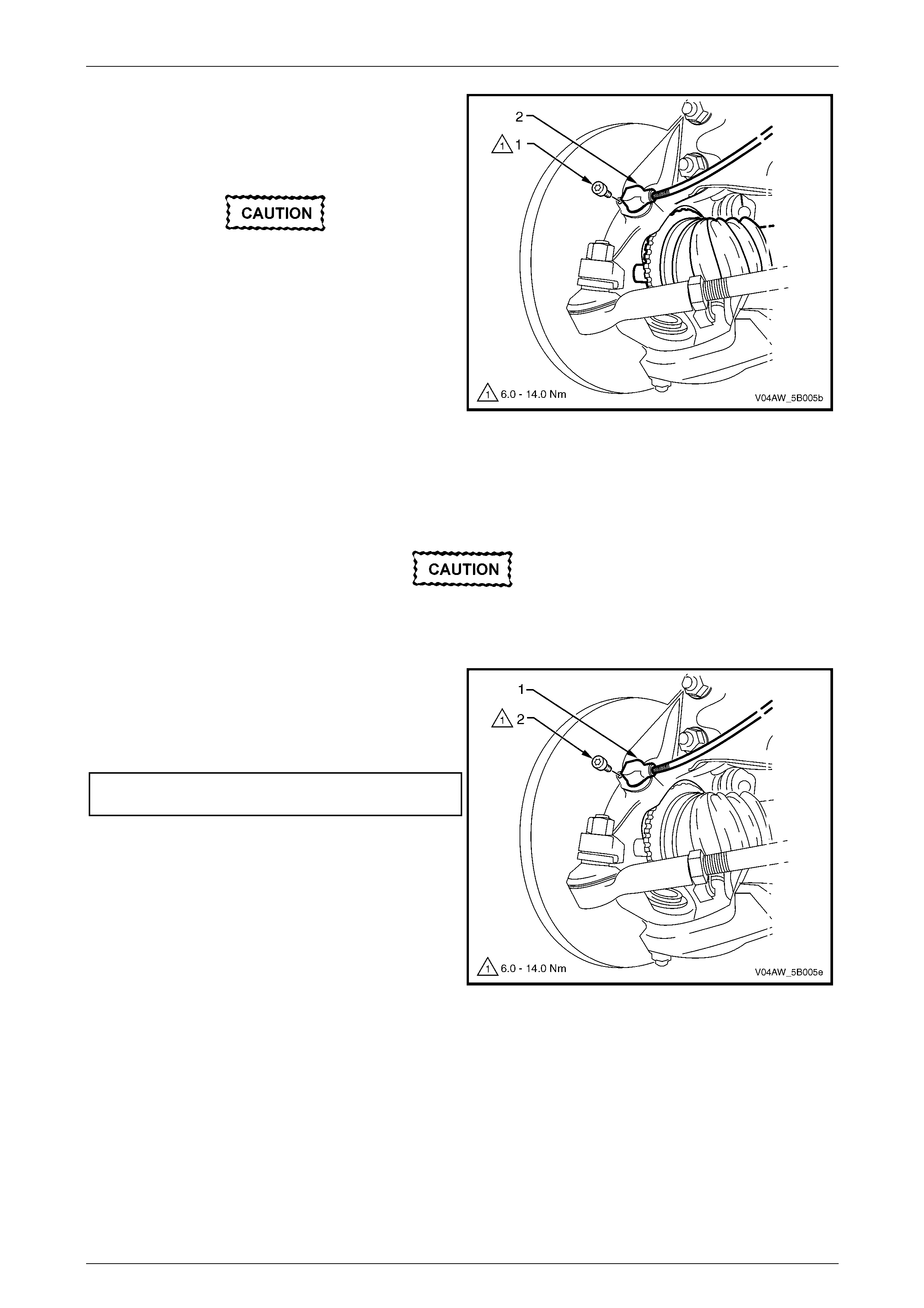
AW D ABS-TCS Page 5B–128
Page 5B–128
7 Remove the screw (1) attaching the front left wheel
speed sensor (2) to the steering knuckle.
8 With a twisting motion, withdraw the front left wheel
speed sensor from the steering knuckle bore.
Do not use a screwdriver or other device to
prise the wheel speed sensor out. Otherwise,
damage to the wheel speed sensor may
occur.
9 Note the front left wheel speed sensor wiring harness
routing then remove the sensor assembly from the
vehicle.
10 Clean the wheel speed sensor to steering knuckle
mating surface. Figure 5B – 93
Reinstallation
Reinstallation of the front left wheel speed sensor is the reverse of the removal procedure noting the following.
A replacement wheel sensor must only be
taken out its packaging immediately before
installing on the vehicle.
1 With a twisting motion, install the front left wheel
speed sensor (1) to the steering knuckle bore.
2 Install the screw (2) attaching the front right wh eel
speed sensor to the steering knuckle and tighten to
the correct torque specification.
Front wheel speed sensor
attaching screw........................................6.0 – 14.0 Nm
Figure 5B – 94
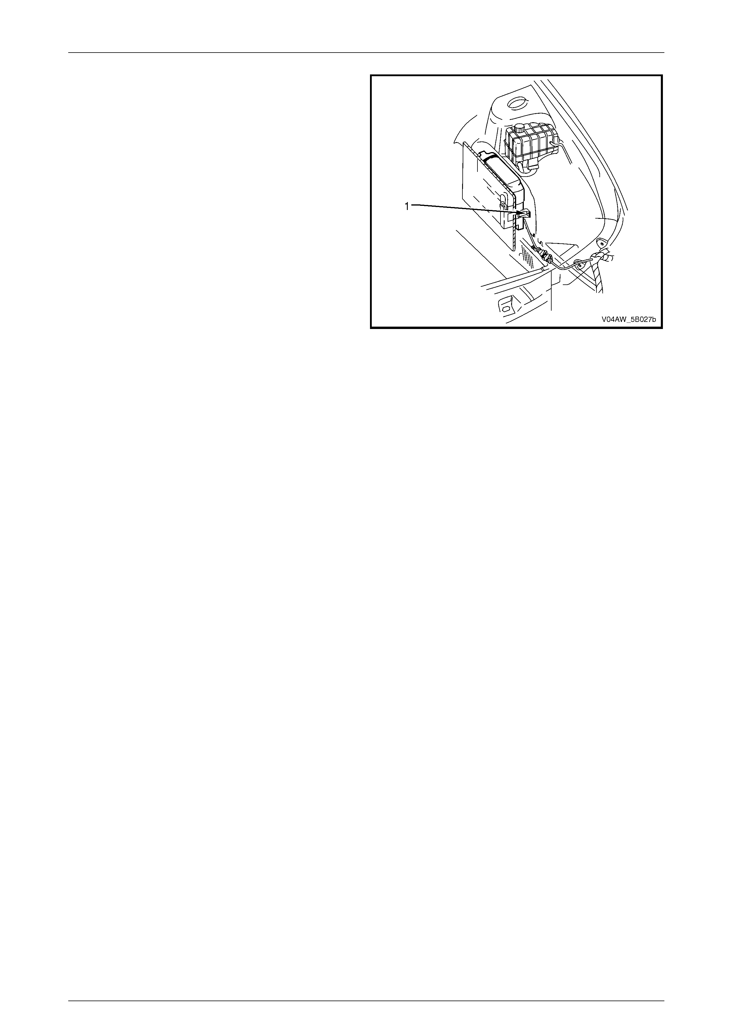
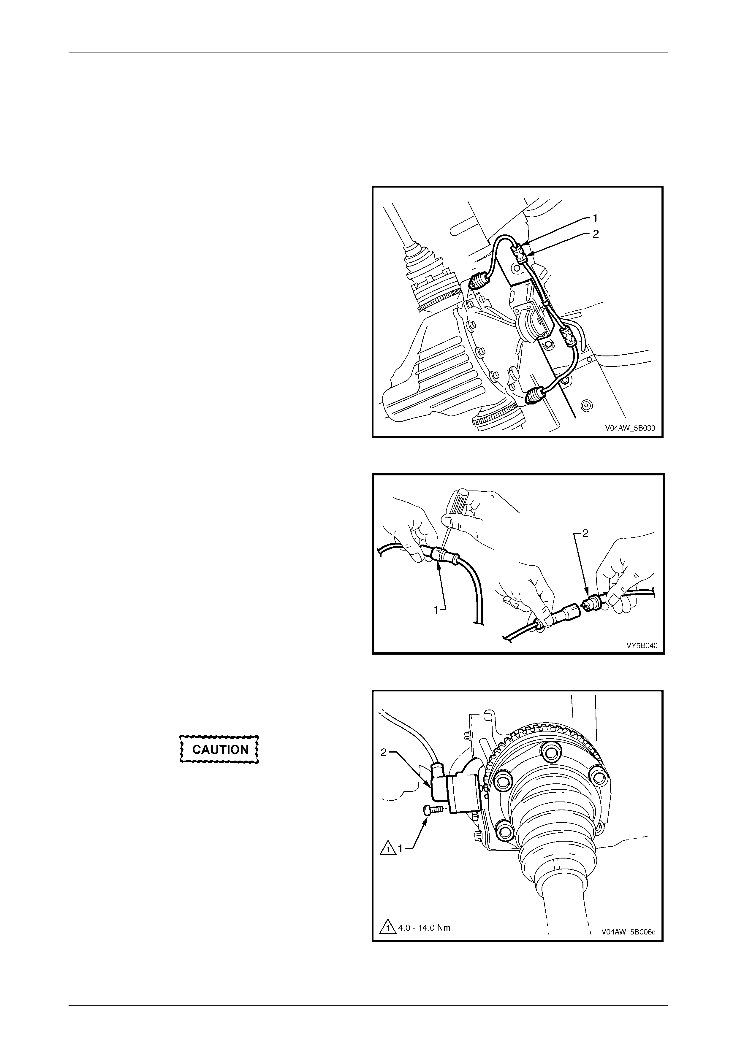
AW D ABS-TCS Page 5B–130
Page 5B–130
9.6 Rear Wheel Speed Sensor
Remove
1 Raise the rear of the vehicle and support using safety stands under trailing arms to support weight of vehicle.
Refer to Section 0A General Information.
2 Disconnect the appropriate sensor lead connector (1)
from its underbody mounting clip (2).
Figure 5B – 96
3 Using a small screwdriver, disconnect the appropriate
wheel speed sensor wiring connector (1) from the
main wiring harness connector.
4 Inspect the connector O-ring (2) and replace if
required.
Figure 5B – 97
5 Remove the screw (1) attaching the appropriate rear
wheel speed sensor (2) to final drive rear cover.
Do not use a screwdriver or other device to
prise the wheel speed sensor out. Otherwise,
damage to the wheel speed sensor may
occur.
6 With a twisting motion, withdraw the appropriate rear
wheel speed sensor from the final drive cover bore.
7 Clean the wheel speed sensor to final drive cover
mating surface.
Figure 5B – 98
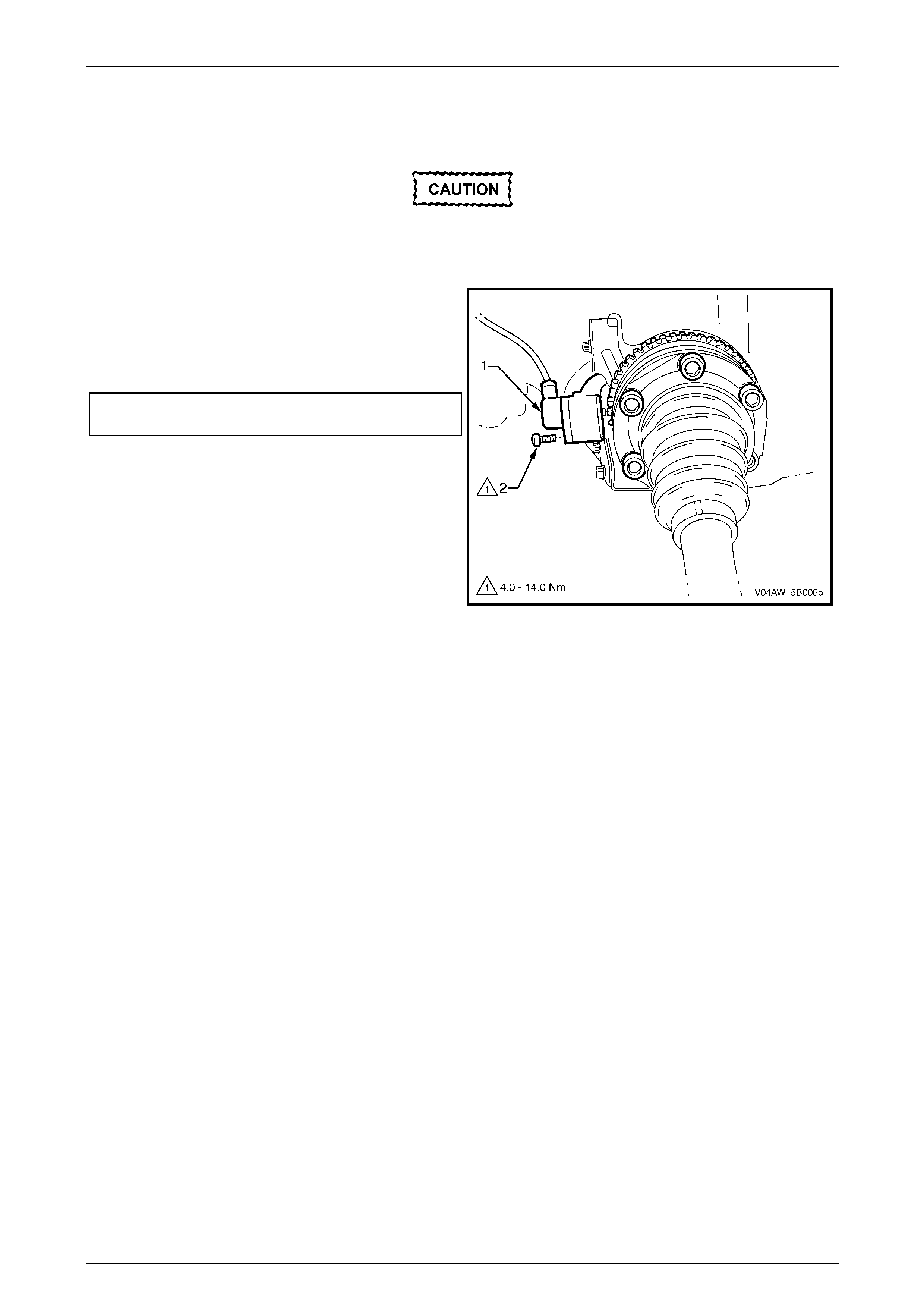
AW D ABS-TCS Page 5B–131
Page 5B–131
Reinstall
Reinstallation of the rear wheel speed sensor is the reverse of the removal procedure noting the following.
A replacement wheel sensor must only be
taken out its packaging immediately before
installing on the vehicle.
1 With a twisting motion, install the appropriate rear
wheel speed sensor (1) to the final drive cover bore.
2 Install the screw (2) attaching the appropriate rear
wheel speed sensor to final drive rear cover and
tighten to the correct torque specification.
Wheel speed sensor attaching screw
torque specification..................................4.0 – 14.0 Nm
3 Check ABS-TCS operation. Refer to
5.2 AWD ABS-TCS Main Diagnostic Table.
Figure 5B – 99
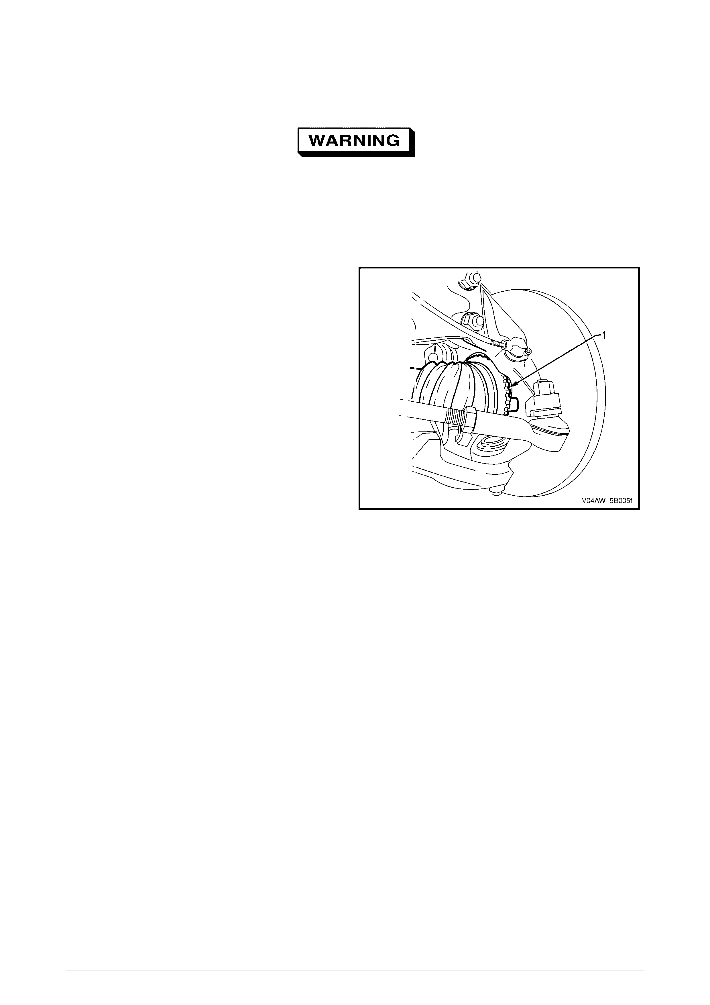
AW D ABS-TCS Page 5B–132
Page 5B–132
9.7 Pulse Rings
If the front constant velocity joint or the rear
axle flange requires replacement, the correct
replacement part must be installed.
Otherwise, ABS-TCS malfunction will occur.
Front Wheel Speed Sensor Pulse Ri ng
The front wheel speed sensor pulse ring (1) is a part of the
front driveshaft constant velocity joint assembly and is not
serviced separately. For the front drive constant velocity
joint service procedure, refer to Section 4B2 Final Drive.
Figure 5B – 100
Rear Wheel Speed Sensor Pulse Ring
NOTE
The rear wheel speed sensor pulse ring is a part
of the axle flange and are not serviced
separately.
Remove
1 Using a floor jack under the centre of the differential carrier, lift the rear of the vehicle and then place safety
stands under the body rear jacking points. Refer to Section 0A General Information.
2 Remove the drive shaft from side of vehicle where the pulse ring is to be removed. Refer to
Section 4B1, Final Drive.
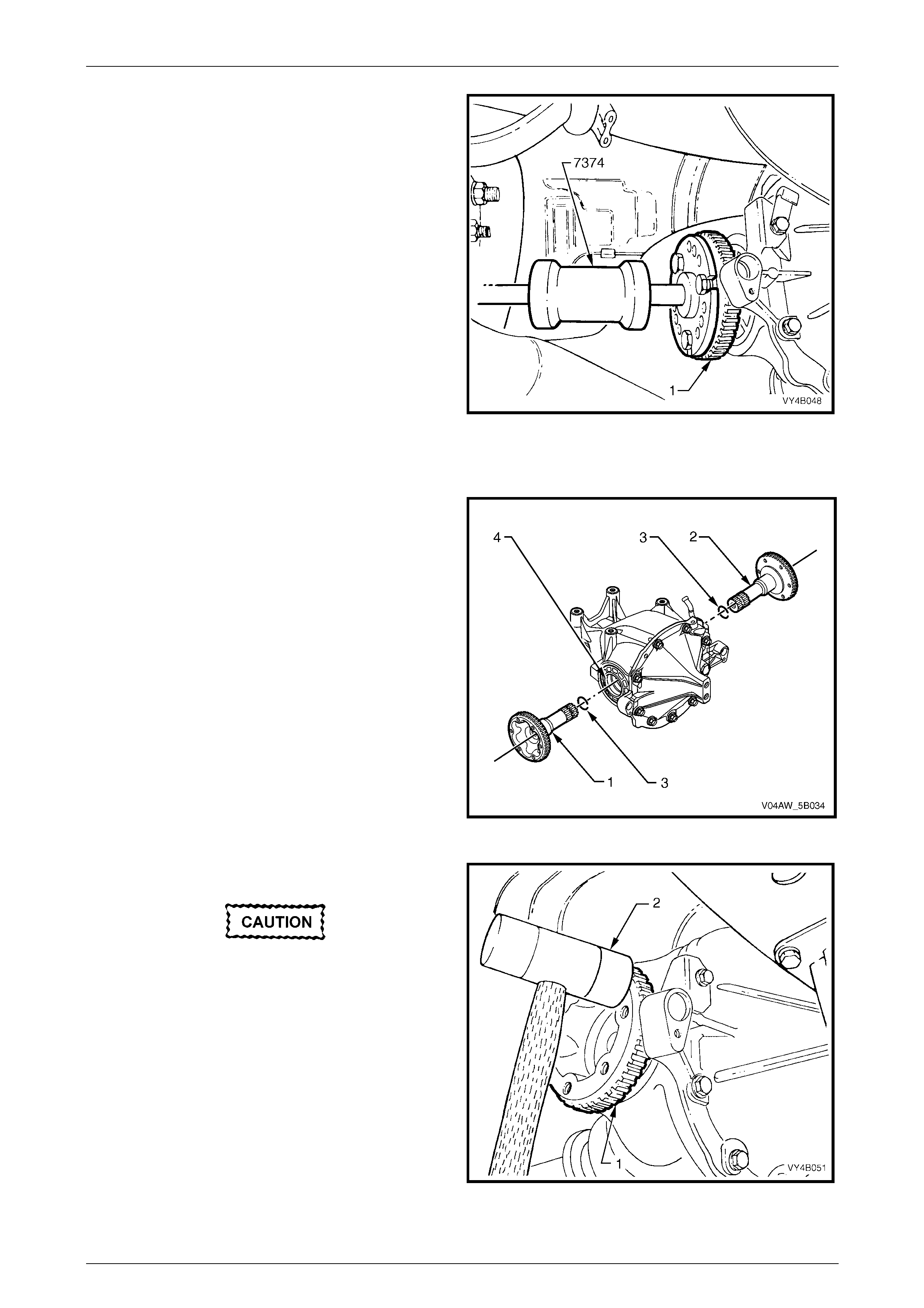
AW D ABS-TCS Page 5B–133
Page 5B–133
3 Remove the appropriate rear wheel speed sensor.
Refer to 9.6 Rear Wheel Speed Sensors.
4 Using a slide hammer, Tool No. 7374 to release the
axle shaft spring clip, remove the inner axle shaft.
As the axle shaft is removed, a small amount of
lubricant may leak from differential carrier.
5 Clean the area around the seal bore and differential
housing to ensure that no foreign matter enters the
axle shaft needle bearing.
Figure 5B – 101
Reinstall
NOTE
The left hand inner axle shaft (1) is shorter in
length than the right hand axle shaft (2).
NOTE
Ensure that the spring clip (3) at the end of the
axle shaft is not damaged and moves freely in
its groove. If necessary, replace the spring clip.
Do not expand the ends of a new clip more than
what is required to allow its installation into the
shaft groove.
1 Lubricate the inner axle shaft seal lips (4) with NLGI
No. 2 Multipurpose grease (lithium soap) grease.
Figure 5B – 102
2 Reinstall the inner axle shaft (1).
To avoid premature seal failure, ensure the
axle shaft splines or its spring clip do not
score or damage the seal lip during
installation.
3 Lightly hit on the end of the axle shaft flange (1) with a
soft faced hammer (2) to compress the spring clip on
the shaft into the clutch cone and side gear splines.
Fully engage the shaft (1) until the clip snaps into the
side gear groove.
Figure 5B – 103

AW D ABS-TCS Page 5B–134
Page 5B–134
4 Reinstall the drive shaft. Refer to Section 4B1 Final Drive.
5 Reinstall the wheel speed sensor. Refer to 9.6 Wheel Speed Sensors.
6 Remove the safety stands and lower the vehicle.
7 Check and fill the differential carrier to the correct level with the specified lubricant. Refer to
Section 4B1 Final Drive.
8 Check the ABS-TCS operation, refer to 5.2 AWD ABS-TCS Main Diagnostic Table.
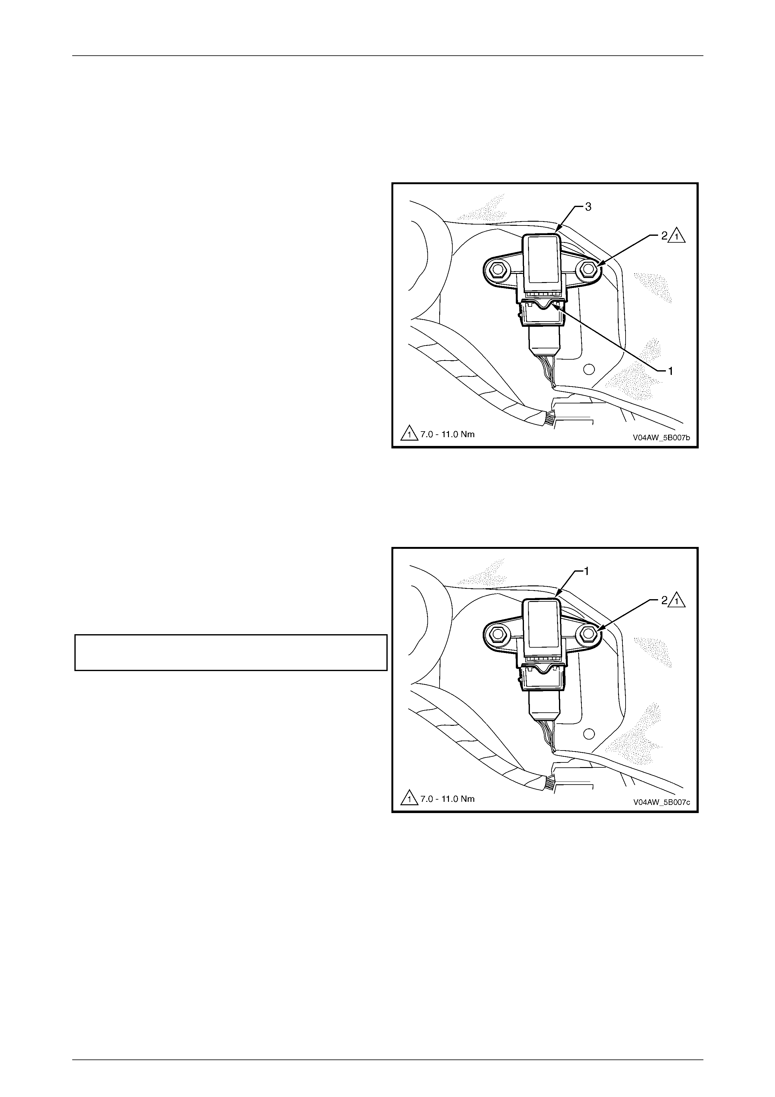
AW D ABS-TCS Page 5B–135
Page 5B–135
9.8 Longitudinal Accelerometer
Remove
1 Remove the floor console assembly. Refer to Section 1A3, Instrument Panel and Console.
2 While pressing down on the longitudinal
accelerometer wiring connector clip (1), disconnect
the longitudinal accelerometer connector.
3 Remove the nut (2), two places, attaching the
longitudinal accelerometer (3).
4 Remove the longitudinal accelerometer from the
vehicle.
Figure 5B – 104
Reinstall
Reinstallation of the longitudinal accelerometer is the reverse of the removal procedure noting the following:
1 Install the longitudinal accelerometer (1) to its correct
position and orientation.
2 Install the nut (2), two places, attaching the
longitudinal accelerometer and tighten to the correct
torque specification.
Longitudinal accelerometer attaching
nut torque specification............................7.0 – 11.0 Nm
3 Check the ABS-TCS operation. Refer to
5.2 AWD ABS-TCS Main Diagnostic Table.
Figure 5B – 105

AW D ABS-TCS Page 5B–136
Page 5B–136
10 Specifications
Wheels speed sensors winding resistance...............................................1.4 - 1.8 kΩ @ 20°c
Front and rear wheel speed sensor air gap.....................................................Non-adjustable
Wheel speed sensor pulse rings ................................................................................ 48 teeth
Brake Fluid.......................................................................................................................Dot 4

AW D ABS-TCS Page 5B–137
Page 5B–137
11 Torque Wrench Specifications
Hydraulic Modulator Brake Pipe Fitting ................................................15.0 Nm
ECU Retaining Screw.............................................................................3.0 Nm
ECU/Hydraulic Modulator Assembly Securing Nut...............................12.0 Nm
Front Wheel Speed Sensor Attaching Screw..............................6.0 – 14.0 Nm
Rear Wheel Speed Sensor Attaching Screw...............................6.0 – 14.0 Nm
Longitudinal Accelerometer Attaching Nut ..................................7.0 – 11.0 Nm
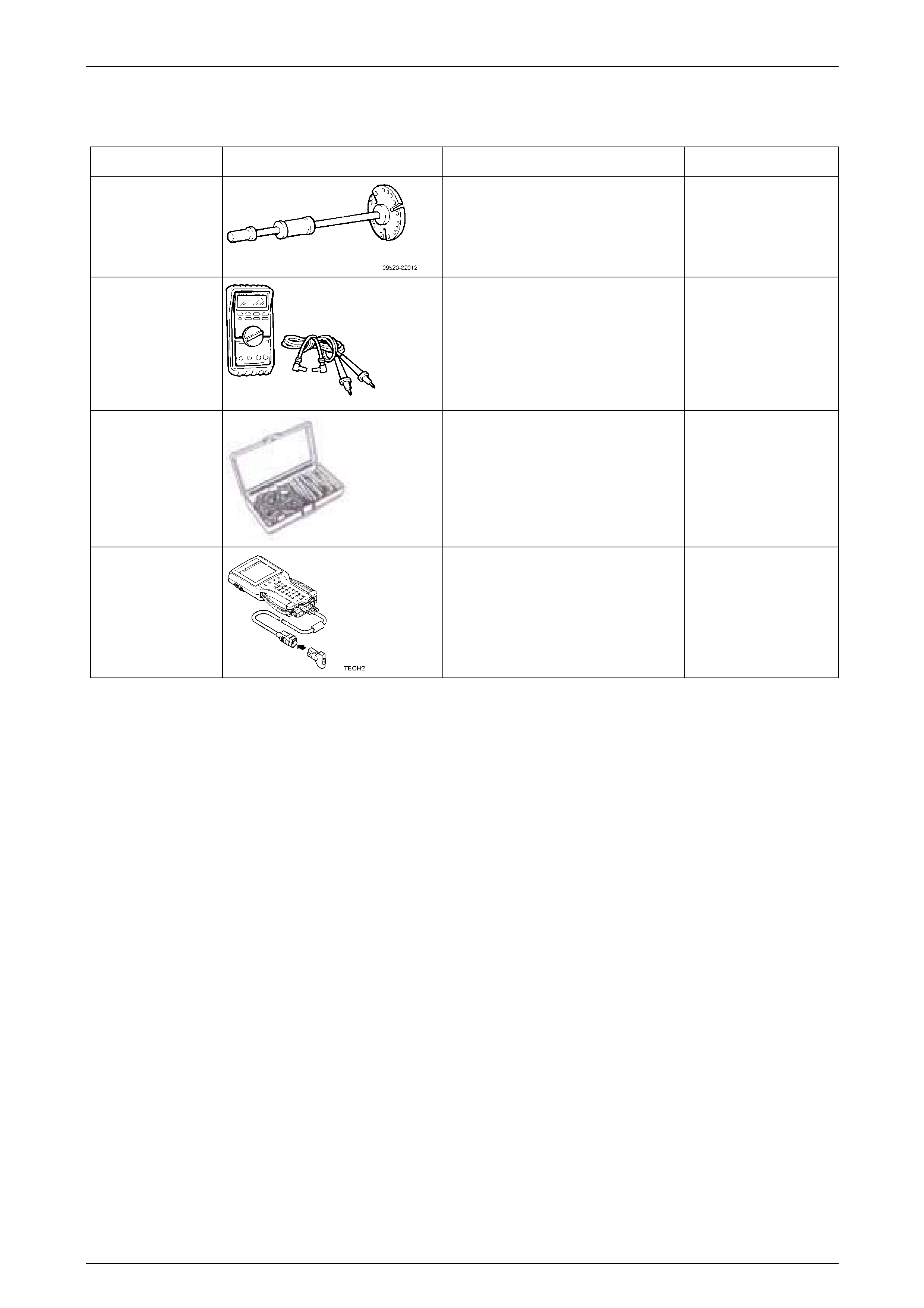
AW D ABS-TCS Page 5B–138
Page 5B–138
12 Special Tools
Tool Number Illustration Description Tool Classification
7374
Slide Hammer & Plate
Used to remove inner axle shafts from
the final drive assembly
Desirable
3588
Digital Multimeter
Also Previously released as J39200
or equivalent.
NOTE: The instrument must have 10
mega ohms impedance and be
capable of reading frequencies.
Mandatory
J35616
Connector Test Adaptor Kit
Used when carrying out electrical
diagnostic circuit checks.
Desirable
70000861
Tech 2 Diagnostic Scan Tool
Previously released.
Mandatory