
Engine Mechanical – GEN III V8 Engine Page 6A3-1
Page 6A3–1
Section 6A3
Engine Mechanical – GEN III V8 Engine
ATTENTION
Before performing any Service Operation or other procedure described in this Section, refer to Section 00
Warnings, Cautions And Notes for correct workshop practices with regard to safety and/or property damage.
1 General Information............................................................................................................................... 2
1.1 General Description...............................................................................................................................................2
Oil Pan.....................................................................................................................................................................2
1.2 Service Notes..........................................................................................................................................................3
Safety ......................................................................................................................................................................3
Environmental Issues............................................................................................................................................3
2 Minor Service Operations..................................................................................................................... 4
2.1 Engine Oil Level Check..........................................................................................................................................4
2.2 Engine Oil Change .................................................................................................................................................5
2.3 Engine Oil Filter Change ........................................................................................................................................6
3 Major Service Operations ..................................................................................................................... 7
3.1 Engine Assembly ...................................................................................................................................................7
General Notes.........................................................................................................................................................7
Remove ...................................................................................................................................................................8
Engine Bay.........................................................................................................................................................8
Under Vehicle...................................................................................................................................................16
Reinstall, Set-up and Testing..............................................................................................................................24
3.2 Oil Pan...................................................................................................................................................................25
Remove .................................................................................................................................................................25
Disassemble .........................................................................................................................................................26
Clean and Inspect.................................................................................................................................................27
Reassemble ..........................................................................................................................................................28
Reinstall ................................................................................................................................................................29
3.3 Oil Pump Pick-up Tube, Screen and Oil Deflector.............................................................................................32
Remove .................................................................................................................................................................32
Clean and Inspect.................................................................................................................................................33
Reinstall ................................................................................................................................................................33
4 Diagnosis.............................................................................................................................................. 35
5 Specifications....................................................................................................................................... 36
6 Torque Wrench Specifications........................................................................................................... 37
7 Special Tools........................................................................................................................................ 39
Techline
Techline
Techline
Techline
Techline
Engine Mechanical – GEN III V8 Engine Page 6A3-2
Page 6A3–2
1 General Information
For the GEN III V8 engine fitted to MY 2004 AWD Wagon models, apart from the changes detailed in this Section, refer
to Section 6A3 Engine Mechanical – GEN III V8 Engine, in the MY2004 VY and V2 Series and in the MY 2003 VY and
V2 Series Service Information.
The unique service procedures required for the GEN III V8 engine fitted to MY 2004 AWD Wagon models, relate to
engine removal and reinstallation and to the engine oil pan removal, reinstallation and related procedures.
1.1 General Description
Oil Pan
The engine oil pan fitted to MY 2004 AWD Wagon models has undergone an extensive re-design process. In addition to
providing mounting points for the front final drive and bearing support assemblies, the oil filter and associated piping
have been relocated.
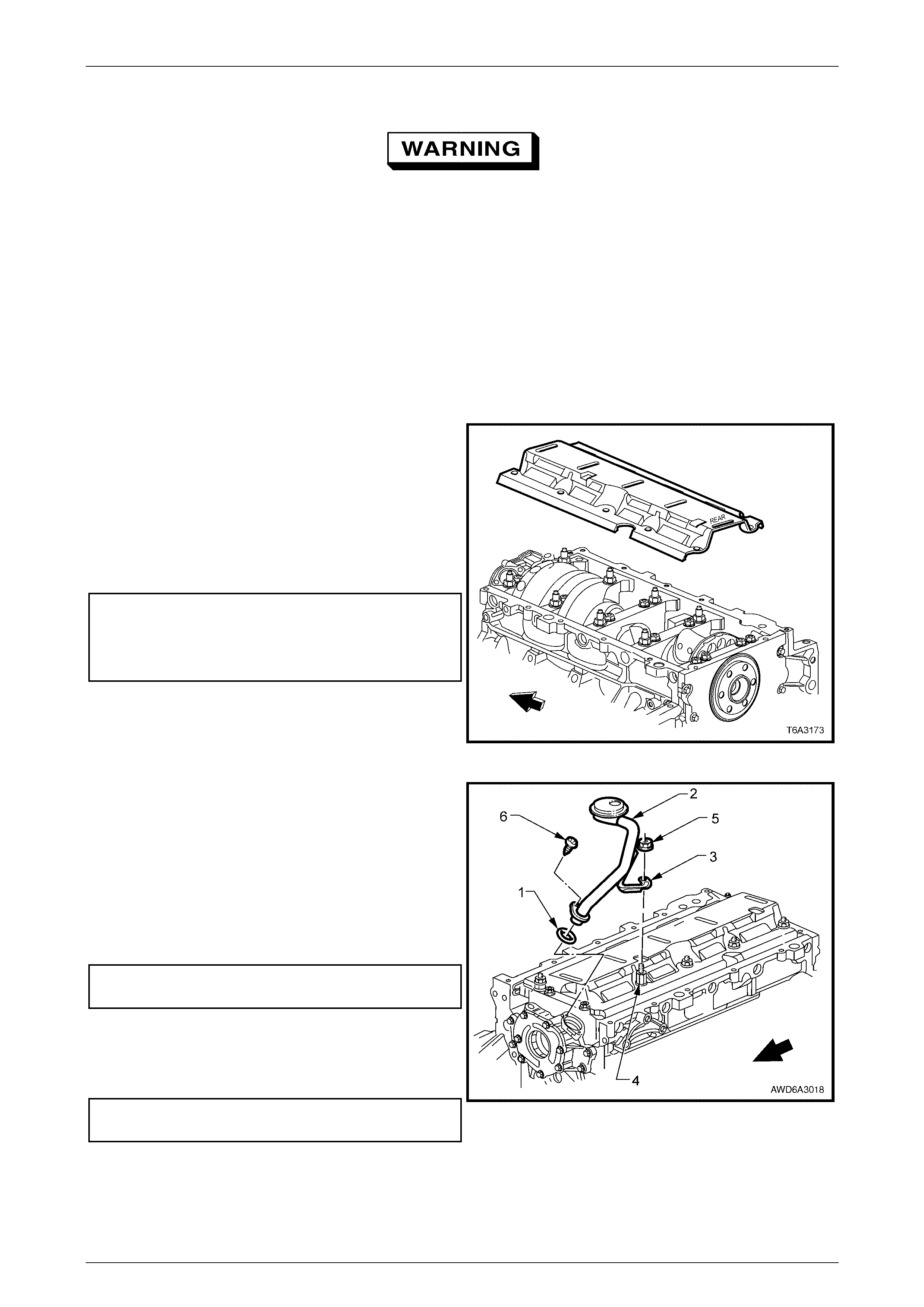
• Internally, the new engine oil pan (1) design results in
an increased engine oil capacity.
Features that have been retained from earlier designs,
include:
1 The crankshaft oil deflector (12), mounted to the main
bearing caps further improves the flow of return oil by:
• Controlling windage.
• Removing return oil from the crankshaft.
• Facilitating the return oil drain back into the oil
pan.
• Reducing engi ne oil aerat ion.
2 The oil pan gasket (15) is a controlled compression
aluminium carrier gasket, using silicone material as a
sealing agent.
3 The oil pan (1) is made from cast aluminium and is an
integral part of the powertrain structure that creates a
360° mounting for the automatic transmission.
4 The oil filter mounting boss is incorporated in the front
of the oil pan and the oil filter (3) screws onto the oil
filter adaptor (2).
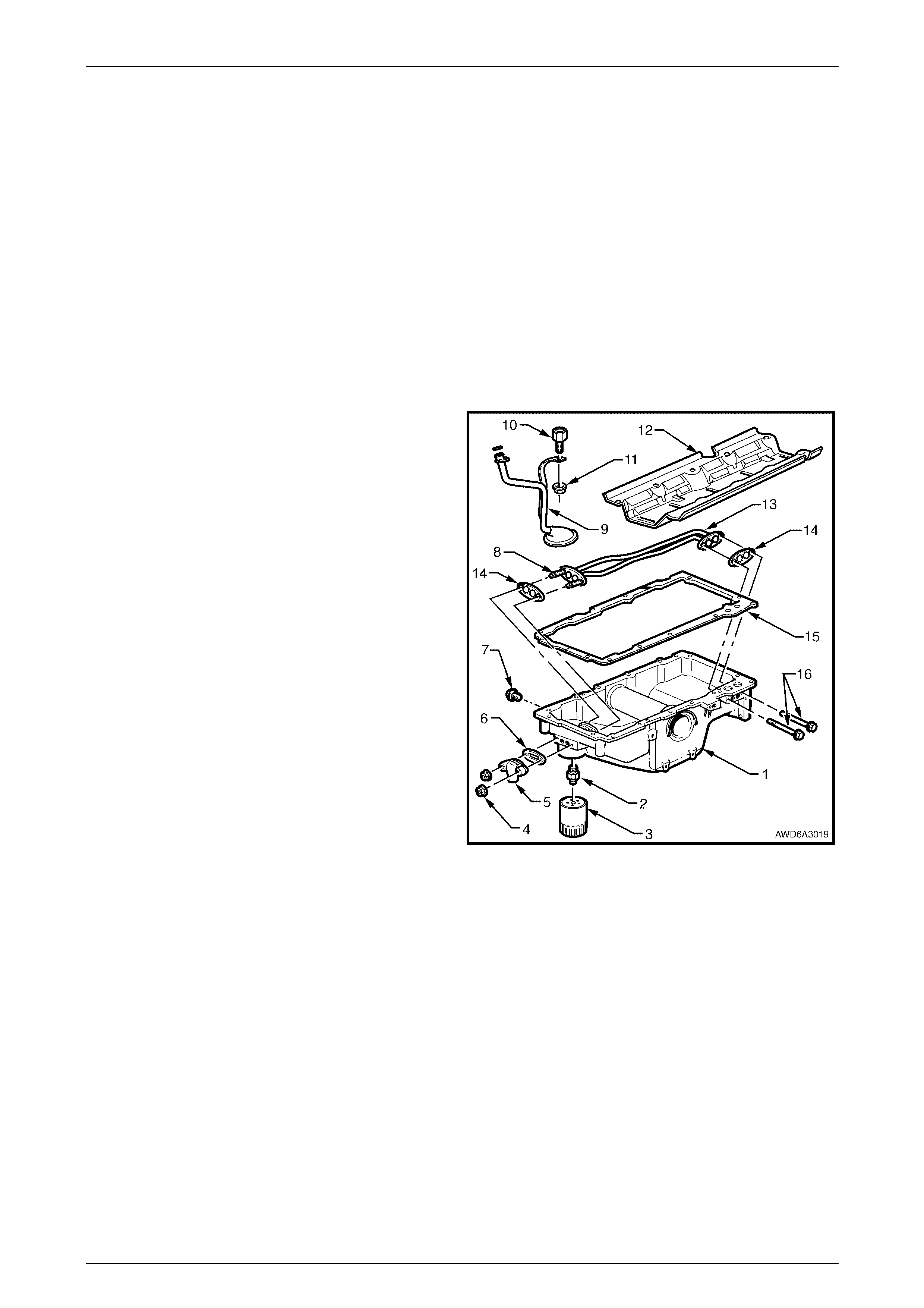
Figure 6A3 – 1
Legend
1 Oil Pan
2 Oil Filter Adaptor
3 Oil Filter
4 Transfer Tube Cover Nut
5 Transfer Tube
6 Transfer Tube Cover Gasket
7 Oil Pan Drain Plug
8 Oil Filter Transfer Tube Mounting Studs
9 Oil Pick-up Tube and Strainer
10 Stud Extension
11 Oil Pick-up Tube Mounting Nut
12 Crankshaft Oil Deflect or
13 Oil Filter Transfer Tubes
14 Oil Filter Transfer Tube Gaskets
15 Oil Pan Gasket
16 Oil Filter Transfer Tube Mounting Bolts

Engine Mechanical – GEN III V8 Engine Page 6A3-3
Page 6A3–3
1.2 Service Notes
Refer to Section 6A3, 1.5 Service Notes, in the MY 2003 VY and V2 Series Service Information for important information
that must be used when working on the GEN III V8 engine. In addition to those points, the following items must also be
read and adhered to:
Safety
This vehicle is fitted with twin radiator electric
cooling fans. When working around the
engine compartment with the engine running
or with the ignition on, keep clear of the fans
as one may start operating without warning.
To avoid serious personal injury, never
remove the screw-on surge tank cap when the
engine is hot, even if the cooling system
requires filling. Sudden release of cooling
system pressure is very dangerous.
Before removing the surge tank cap, allow the engine to cool, then place a shop rag over the surge tank cap and then
slowly turn the cap anti-clockwise, to loosen. Do not spin the cap off! If there is any residual pressure in the cooling
system, it can then be released into the dam under the cap and out through the drain hose onto the ground. When all
pressure has been dispersed in this way, the cap can then be fully removed.
Environmental Issues
To reduce the impact on the environment and the maintenance cost, whenever the coolant is drained from the GEN III
V8 engine, the service records are to be checked to determine when the coolant was last changed. If more than six
months life is left before the next coolant change, then the following procedure is to be followed:
1 When draining the coolant from the engine, use a clean container of at least 15 litres capacity and ensure that the
coolant is not cont aminated in the draining proc es s.
2 After repairs have been completed, refill the engine cooling system with the drained coolant.
3 Top up as required, using a 50% mixture of DEX-COOL® long life coolant to GM Specification 6277M to 50%
clean, good quality water. Refer 2.2 Coolant Maintenance and 2.3 Draining and Filling Cooling System, in
Section 6B3 Engine Cooling – GEN III V8 Engine, in the MY 2003 VY and V2 Series Service Information.
Engine Mechanical – GEN III V8 Engine Page 6A3-4
Page 6A3–4
2 Minor Service Operations
2.1 Engine Oil Level Check
With the re-calibrated oil level dipstick to suit the extra oil capacity engine oil pan, this maintenance item now requires
revision.
1 The engine must be at normal operating temperature (drive the vehicle for 15 minutes).
2 Park the vehicle on a level surface.
NOTE
• Do not check the oil level for at least 10
minutes after the engine is switched-off. This
allows time for the oil to drain back into the oil
pan.
• A sloping surface will affect the accuracy of
the measurement.
3 Remove the dipstick and wipe clean.
4 Reinstall the dipstick. Ensure that it is fully seated. Leave for several seconds and remove slowly to avoid smearing
the oil (level); then hold the dipstick horizontally to prevent the oil (level) moving along the dipstick.
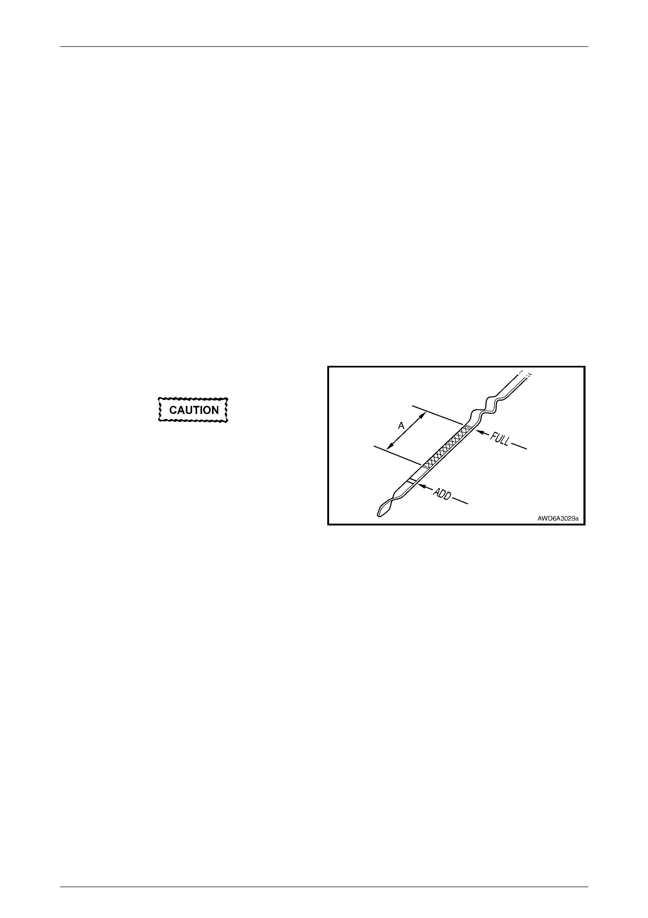
5 Check the oil level is indicated on the blade of the
dipstick.
Do not fill over the 'FULL' mark.
6 If the level is lower than, or close to the 'ADD' mark,
top-up the engine with enough oil to reach the 'FULL'
mark.
NOTE
As a guide to the amount of oil to add, the
crosshatch area (A) represents about 1 litre of oil
and the 'ADD' to 'FULL' marks, represents about
1.6 litres of oil is required.
Figure 6A3 – 2
7 Allow several minutes for the added oil to drain down into the oil pan, then recheck the oil level.
Engine Mechanical – GEN III V8 Engine Page 6A3-5
Page 6A3–5
2.2 Engine Oil Change
NOTE
• Quicker and more complete draining will
occur if the engine oil is at operating
temperature. However, care must be taken to
avoid scalding from the hot oil.
• While the oil pan is aluminium, it is fitted with
a steel thread insert to increase durability of
the thread and to avoid thread tearing when
the drain plug is removed from a hot engine.
• It is also recommended that the oil filter is
changed at each engine oil change, refer
2.3 Engine Oil Filter and Adaptor, in this
Section.
1 Raise the engine hood and remove the oil fill cap.
2 Raise the vehicle and support in a safe, level manner. This is to ensure complete draining. Refer to
Section 0A General Information, in the MY 2004 AWD Wagon Service Information.
3 If fitted, remove the oil pan under-tray.
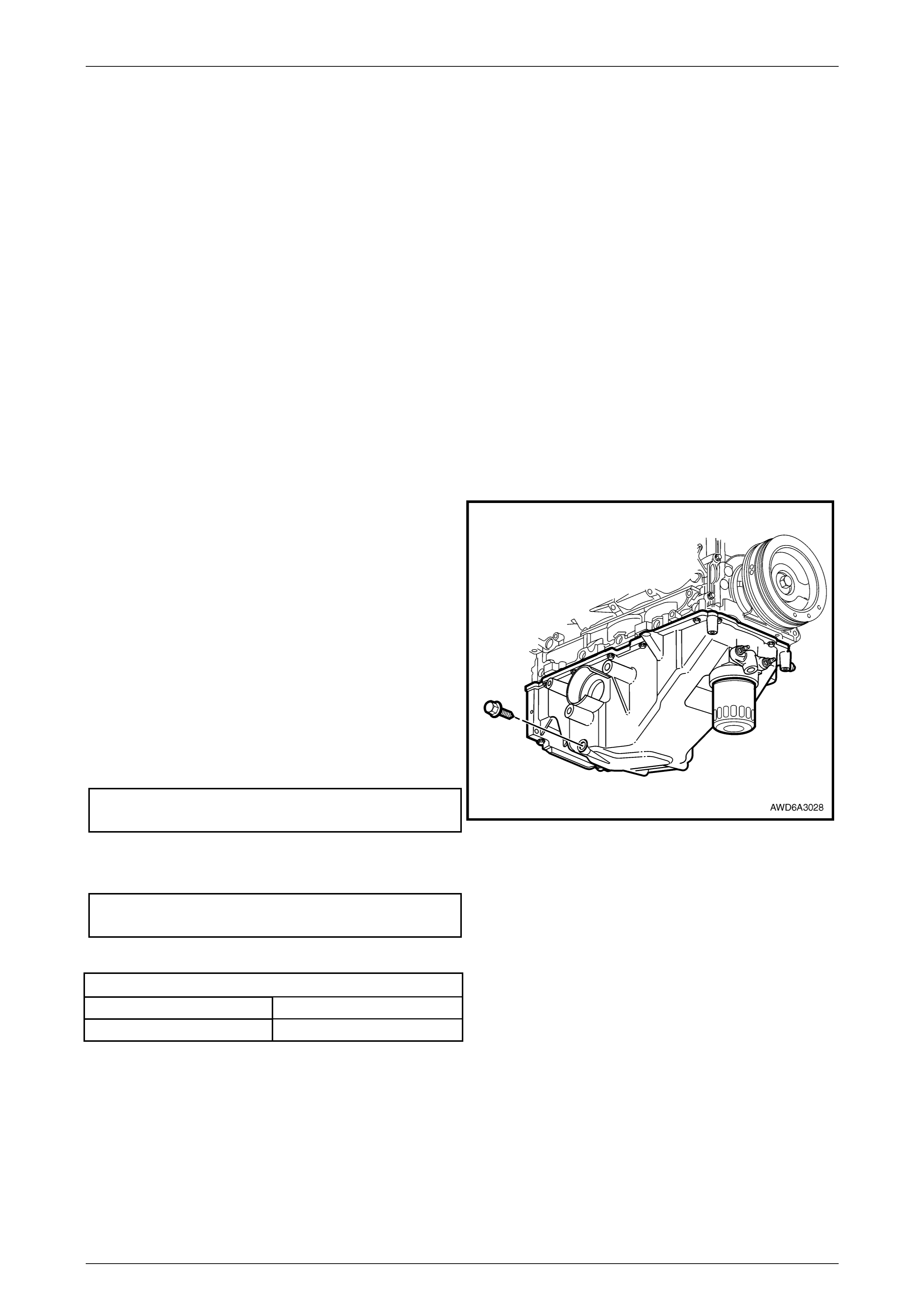
4 Clean any foreign material from around the oil pan
drain plug.
5 Place an oil drain tray beneath the engine.
6 Using a 15 mm ring spanner, remove the drain plug,
catch the draining oil into the drain tray, taking care to
avoid scalding with the hot waste oil in the process.
7 When the oil has drained sufficiently, check the quality
of threads both on the drain plug and the thread insert
in the oil pan, i.e. thread condition is sound and the
insert is not loose in the oil pan.
8 Reinstall the drain plug, after inspecting the drain plug
seal which may be re-used if not cut or damaged.
Tighten the drain plug to the correct torque
specification.
Engine oil pan drain plug
torque specific atio n ..............................................25 Nm
Figure 6A3 – 3
9 As required, reinstall the oil pan under-tray and tighten the four bolts to the correct torque specification.
Oil pan under-tray bolt
torque specific atio n ..............................................25 Nm
10 Lower the vehicle and fill the crankcase with the required amount of GF2 10W – 30 SJ lubricant.
Engine Oil Capacity
Without Oil Filter Change ~ 7.6 litres
With Oil Filter Change ~ 8.0 litres
NOTE
Synthetic oils of the stated viscosity are also an
acceptable eng ine lubricant.
11 Start the engine and check for oil leaks.
Engine Mechanical – GEN III V8 Engine Page 6A3-6
Page 6A3–6
2.3 Engine Oil Filter Change
LT Section No. – 01-500
NOTE
The oil filter should be replaced at the time or
distance intervals, specified in the Owner’s
Handbook or whenever the engine oil is changed.
1 Raise the engine hood and remove the oil fill cap.
2 Raise the vehicle and support in a safe, level manner. This is to ensure complete draining. Refer to Section 0A
General Information, in the MY 2004 AWD Wagon Service Information.
3 If fitted, remove the oil pan under-tray.
4 Drain the engine oil as detailed in 2.2 Engine Oil Change, in this Section.
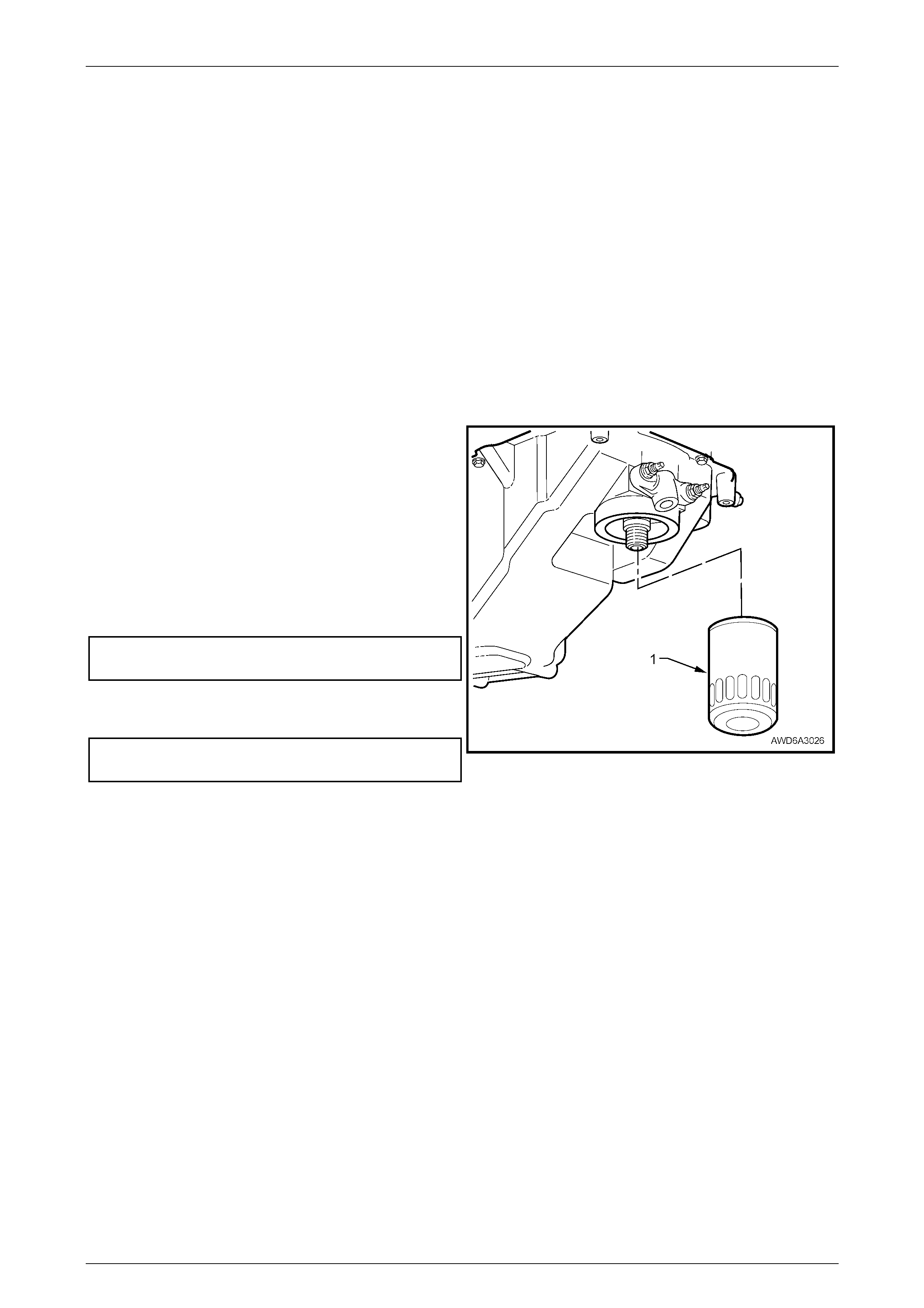
5 Remove the oil filter (1), using a commercially
available tool, tak ing care to avoid being sca lde d w ith
the hot waste oil.
6 After checking that the oil filter seal has not adhered to
the oil pan flange, inspect the oil filter sealing surface
for scratches or other damage and check the oil filter
adaptor threads for damage.
7 Smear some new engine oil onto the new filter seal,
then install filter assembly to engine.
8 Tighten oil filter to the correct torque specification.
Engine oil filter
torque specific atio n ..............................................30 Nm
9 If required, reinstall the oil pan under-tray and tighten
the four bolts to the correct torque specification.
Engine oil pan under-tray
bolt torque specification........................................25 Nm
10 Lower the vehicle and fill the crankcase with 8.0
litres of the recommended, new lubricant. Refer to
2.2 Engine Oil Change in thi s Sec tion, for the
recommended procedure.
11 Start the engine and check for oil leaks.
Figure 6A3 – 4

Engine Mechanical – GEN III V8 Engine Page 6A3-7
Page 6A3–7
3 Major Service Operations
ATTENTION
All fasteners are important attaching parts as they affect the performance of vital components and/or could
result in major repair expense. Where specified in this section, fasteners MUST be replaced with parts of the
same part number or an approved equivalent. Do not use fasteners of an inferior quality or substitute design.
Torque values must be used as specified during reassembly to ensure proper retention of all components.
Throughout this section, fastener torque wrench specifications may be accompanied with the following
identification marks:
!
!!
! Fasteners must be replaced after loosening.
"
""
" Vehicle must be at curb height before final tightening.
#
##
# Fasteners either have micro encapsulated sealant applied or incorporate a mechanical thread lock and
should only be re-used once. If in doubt, replacement is recommended.
If one of these identification marks is present alongside a fastener torque wrench specification, the
recommendation regarding that fastener must be adhered to.
3.1 Engine Assembly
LT Section No. – 00-500
ATTENTION
The following fasteners MUST be replaced when performing these operations:
!
!!
! Engine mount retaining nuts - All.
!
!!
! Torque converter to engine flexplate retaining bolts.
!
!!
! Exhaust pipe flange to exhaust manifold retaining nuts - All.
!
!!
! Rear propeller shaft front coupling retaining nuts and bolts.
!
!!
! Front driveshaft outer retaining nut.
#
##
# Front control arm ball joint retaining nut.
#
##
# Exhaust manifold attaching bolts.
General Notes
1 With the designed method of attaching front powertrain components to the engine oil pan, the preferred method of
removing the engine from the vehicle is to lower the engine, transmission, transfer case and front suspension
cradle as a complete assembly, below the vehicle.
2 There are a number of different approaches that can be taken during the removal operation. For example:
a It is recommended that a scissor lift hydraulic mobile table is used to lower the engine, transmission/transfer
case and front suspension cradle from the vehicle. If this approach is used, then the engine hood does not
need to be removed. However, if a scissor lift is not available, then the engine hood will need to be removed,
to allow overhead lifting equipment to be used to lower the assemblies from the vehicle. This is the reason for
including the engine hood removal in this procedure.
b The procedure as detailed, leaves both front suspension struts installed in the vehicle, with wooden props
supporting each against the inner fender. This results in the braking system hydraulics being left intact and
does not require the assistance of two extra people to support the suspension legs during the lowering and
raising of the assemblies from and to the vehicle. However, the struts can be lowered with the remainder of
the assemblies, provided both brake calipers are removed from the steering knuckles and supported by tie
wire to a convenient under fender anchor point. This approach does mean that the caliper attaching bolts
must be replaced on reassembly.
Engine Mechanical – GEN III V8 Engine Page 6A3-8
Page 6A3–8
c As detailed, there are a number of instances where removal of fasteners is stated, before the assemblies are
lowered from the vehicle; e.g. lower transmission to engine oil pan bolts and lower engine mounting nuts.
These recommendations make removal; of these fasteners easier at this time rather than afterwards, when
the assemblies are lowered onto the flat scissor lift table. If overhead lifting equipment is used, then the timing
of these fastener removals is variable. Usually though, there is no safety device used in conjunction with over
head lifting equipment and the implications of this must be taken into account.
Remove
Engine Bay
Disconnection of the battery affects certain
vehicle electronic systems. Refer to
Section 00 CAUTIONS, 5. Battery
Disconnection Procedures before
disconnecting the battery
1 Disconnect the battery ground cable.
Never remove the screw-on pressure cap
when the engine is hot. Sudden release of
cooling system pressure is very dangerous
and could cause personal injury.
2 Loosen the screw-on pressure cap on the coolant surge tank to relieve any system pressure, then remove cap.
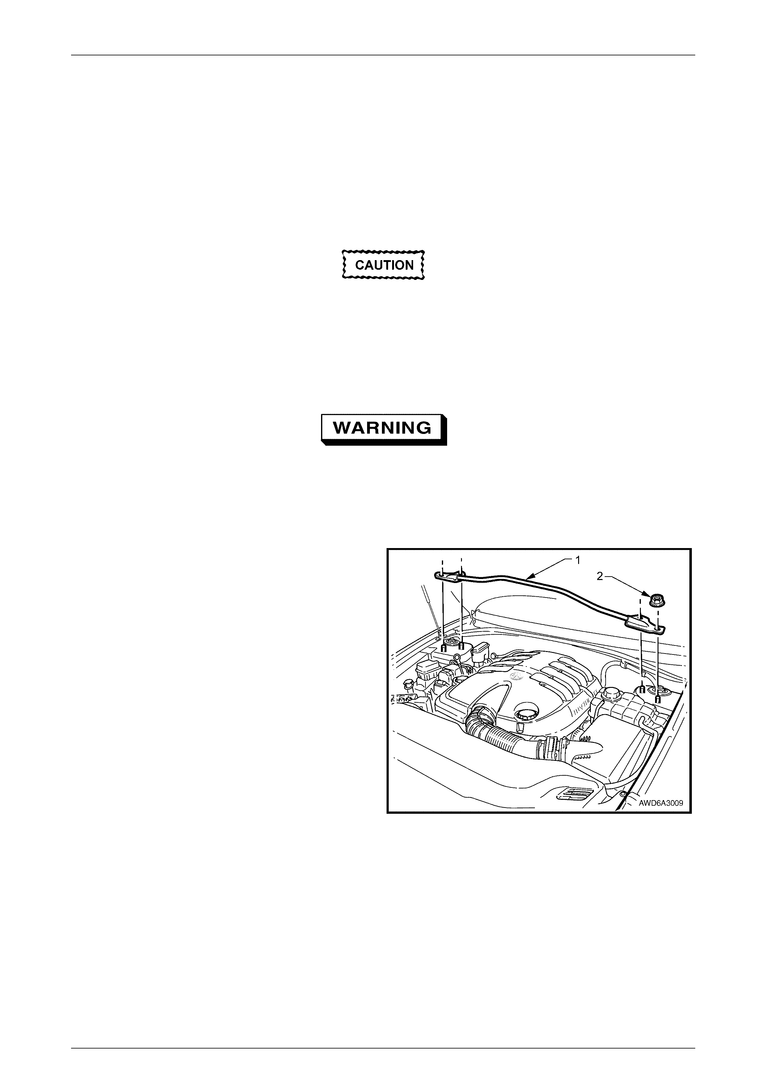
3 Remove the front strut tower brace (1) by removing
the two nuts (2) on each side. Lift the brace free from
the mounting studs.
Figure 6A3 – 5
Engine Mechanical – GEN III V8 Engine Page 6A3-9
Page 6A3–9
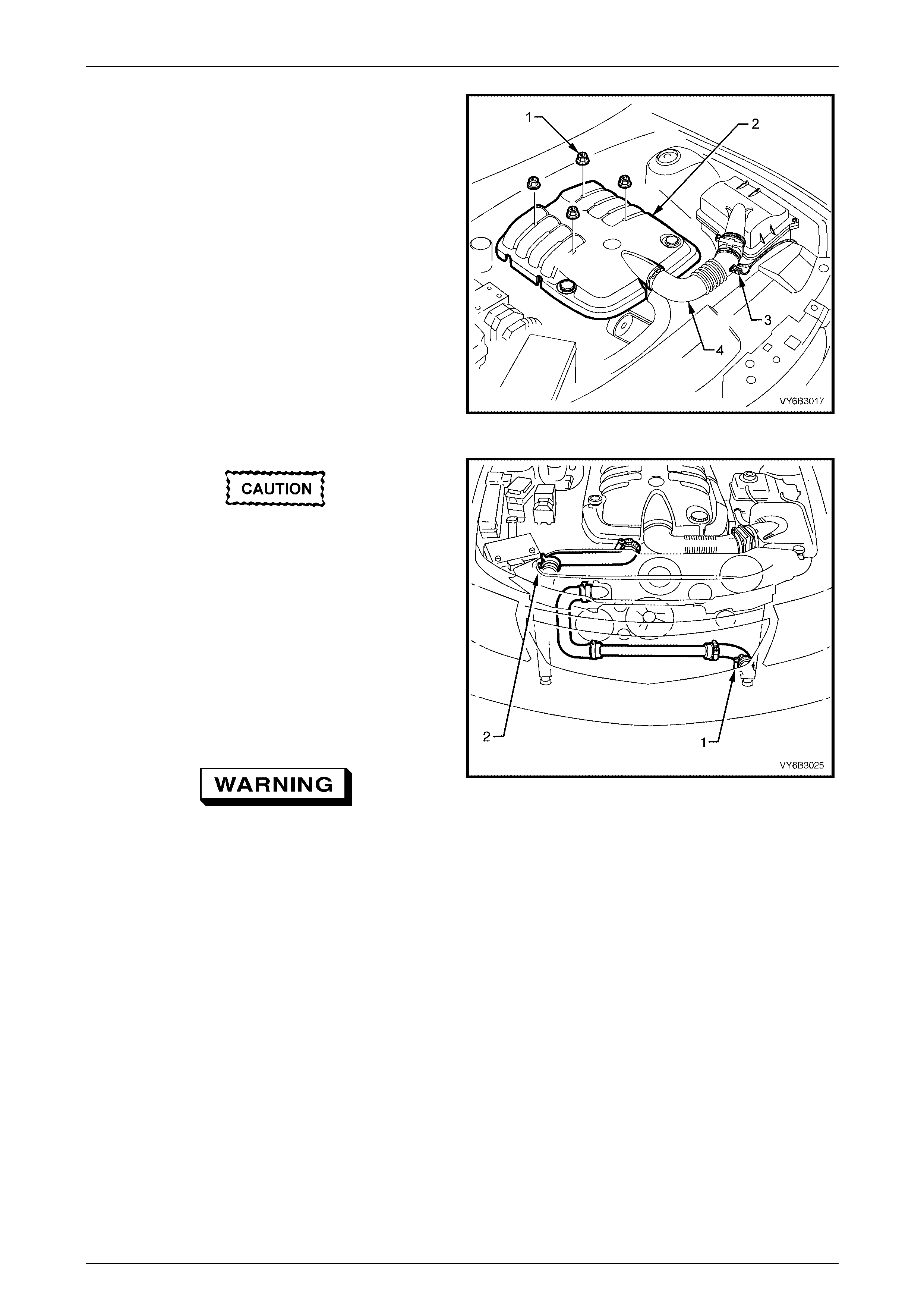
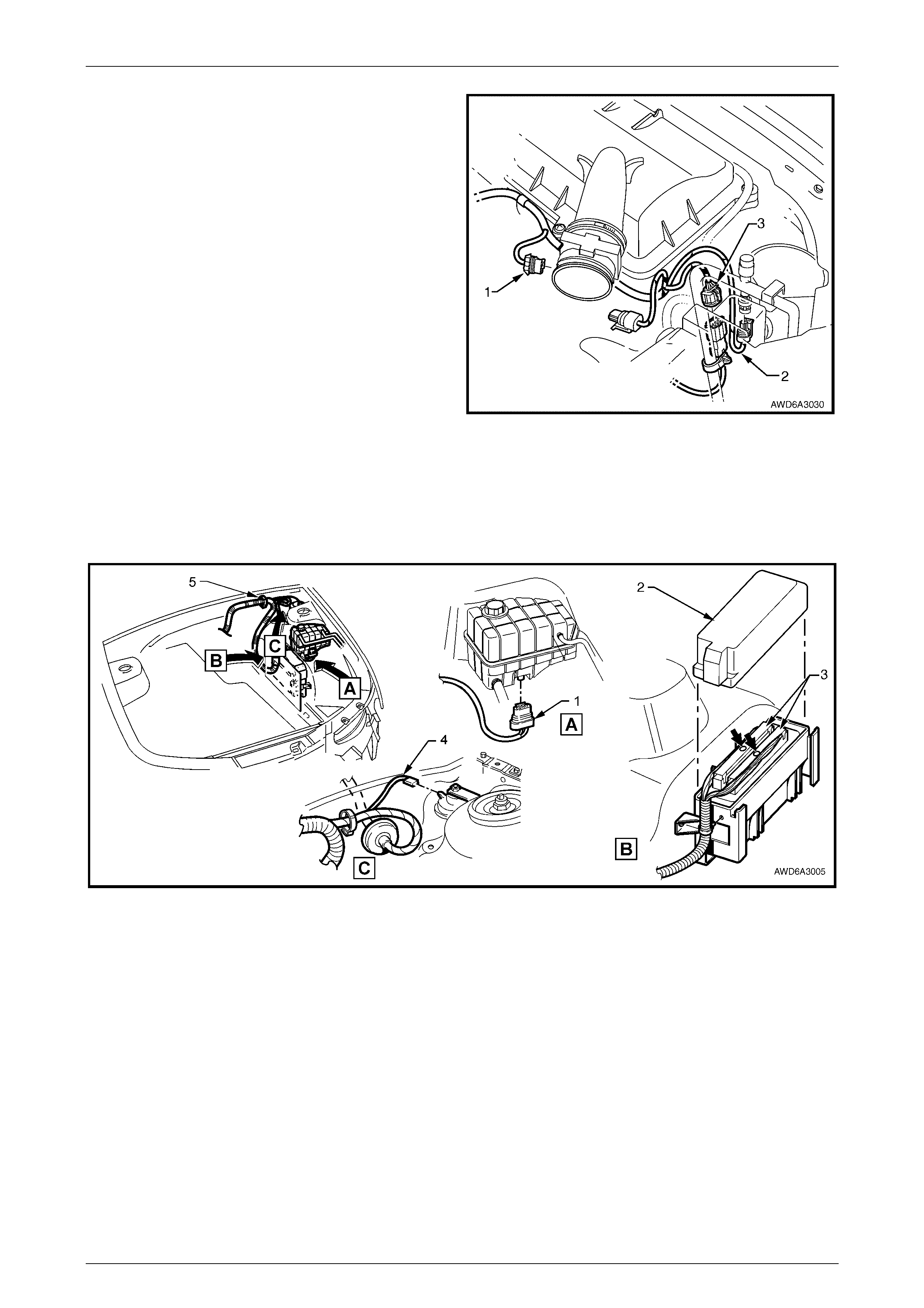
4 Remove the four engine dress cover decorative nuts
(1), then remove the dress cover (2) from the engine.
5 Remove the intake air temperature sensor wiring
harness connector (3), then loosen both hose clamps
securing the intake duct to the MAF sensor and the
throttle body. Remove the duct, clamps and intake air
temperature sensor assembly from the engine.
6 De-pressurise fuel rail. Refer to 2.13 Fuel System
Pressure Relief, in Section 6A3 Engine Mechanical -
GEN III V8 Engine, in the MY 2003 VY and V2 Series
Service Information.
Figure 6A3-6
Before draining the engine coolant, refer to
Environmental Issues in 1.2 Service Notes, in
this Section.
7 Place a suitable drain tray under the engine then,
working under the vehicle, loosen the worm drive hose
clamp (1) on the lower hose at the left side radiator
tank, remove the hose from the radiator and drain the
coolant into the drain tray.
8 Working from the engine bay, loosen the second worm
drive hose clamp securing the lower left hand hose to
the transfer tube, then remove the lower left hand
hose from the vehicle.
Wear eye protection when handling spring
type clamps to avoid possible personal eye
injury.
Figure 6A3 – 7
9 Remove the five scrivets securing the radiator upper shroud, then remove the shroud form the engine bay.
10 Loosen top radiator worm drive hose clamp at the engine end and the spring type clamp at the radiator (2).
Remove the top hose from the engine.
Engine Mechanical – GEN III V8 Engine Page 6A3-10
Page 6A3–10
NOTE
If overhead lifting equipment is to be used to
lower the engine, transmission/transfer case and
front suspension cradle assemblies from the
vehicle, then removal of the engine hood will be
required.
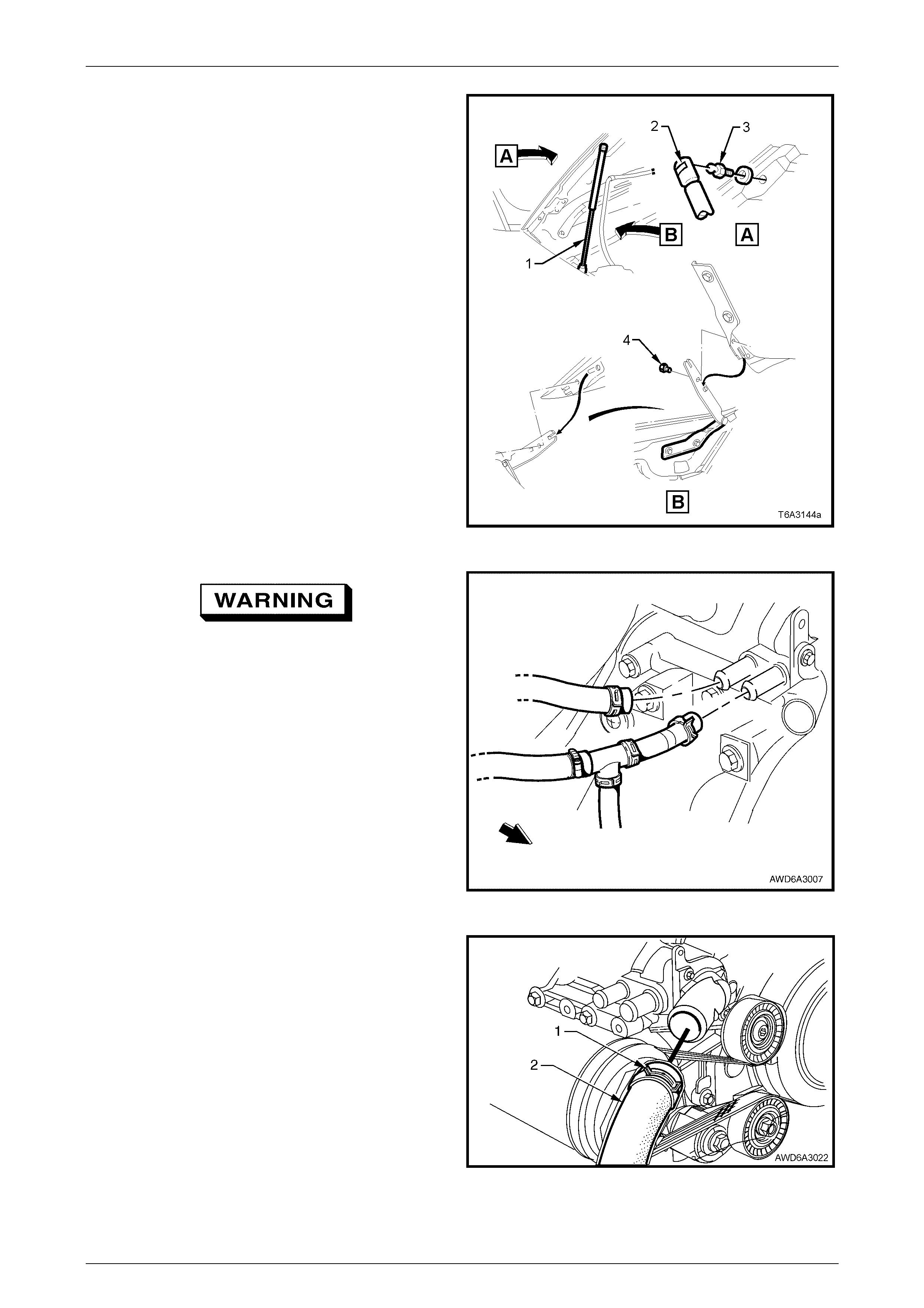
11 With engine hood adequately supported, remove clips
(2) securing upper ends of struts (1) to hood pivots (3).
Disengag e struts (1) from hood pivots (3) and lay
struts onto inner fender panel.
12 Using an assistant to hold the hood assembly, remove
the engine hood bracket to hinge attaching bolts (4),
as shown, then carefully lift the hood assembly clear of
the vehicle.
Figure 6A3 – 8
Wear eye protection when handling spring
type clamps to avoid possible personal eye
injury.
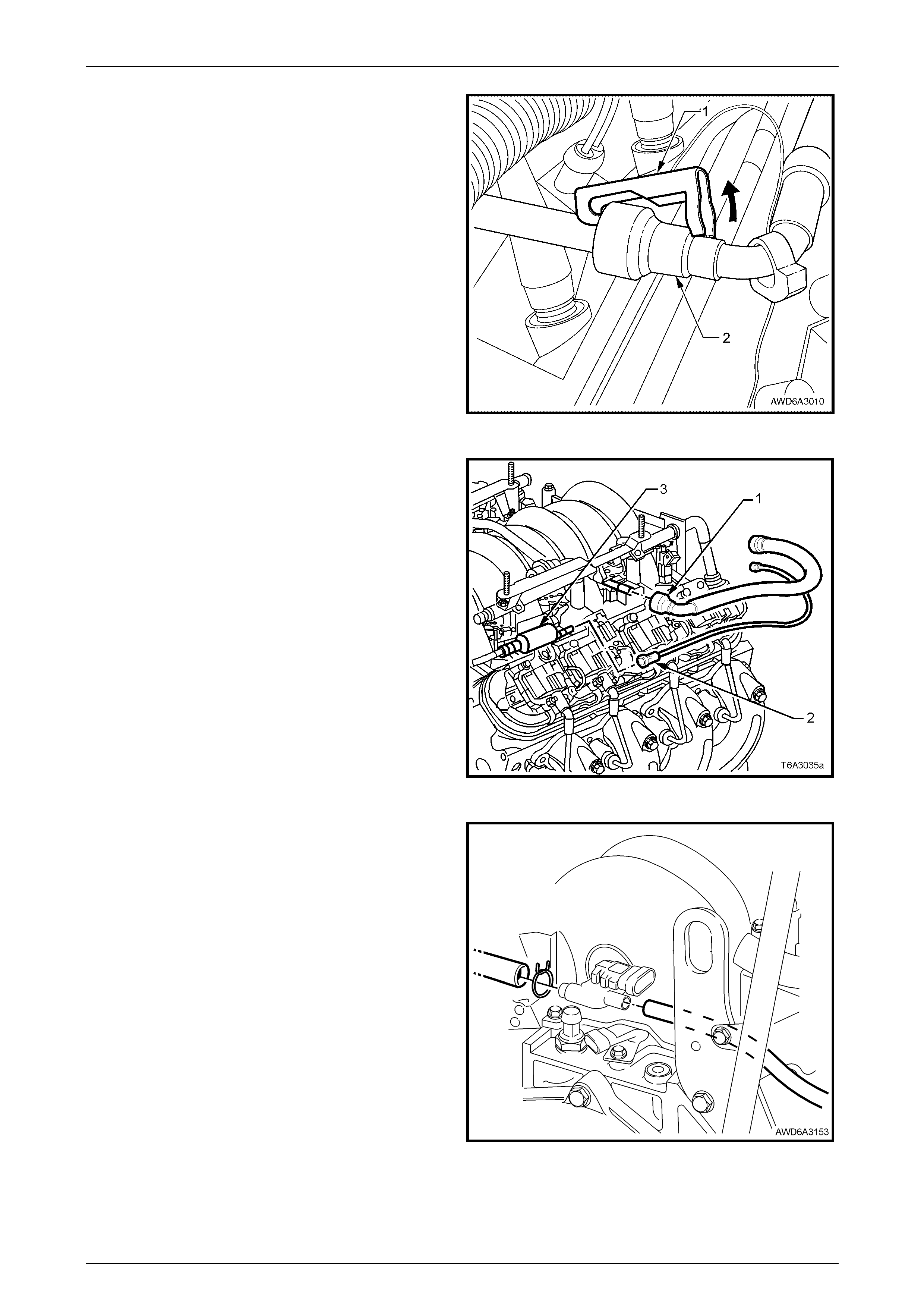
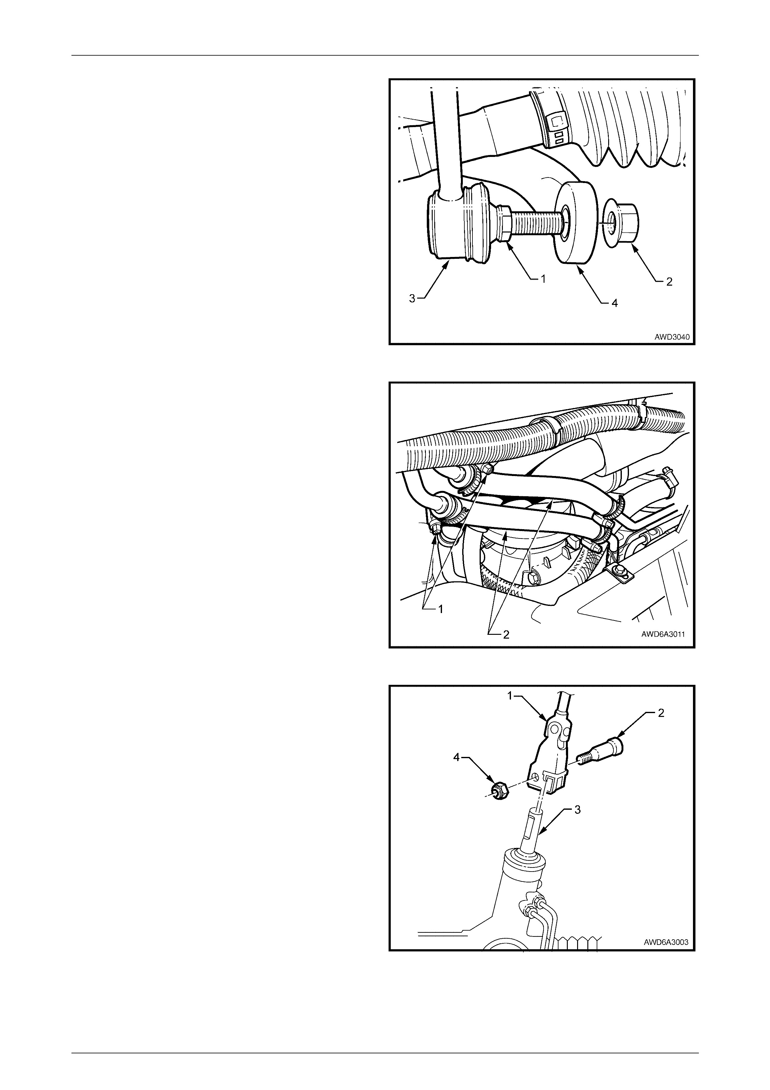
13 Remove both heater hose clamps at the engine water
pump, taking note of the hose layout. Plug open ends
to prevent dirt entry.
Figure 6A3 – 9
14 Tension, then slide the spring type hose clamp (1)
back over the lower radiator hose (2) at the coolant
pump end.
15 Remove the hose from the coolant pump and plug
open ends to prevent dirt entry. Secure the hose to
one side using tie wire or similar.
Figure 6A3 – 10
Engine Mechanical – GEN III V8 Engine Page 6A3-11
Page 6A3–11
16 Recover refrigerant charge, refer to Section 2C Air
Conditioni ng – Servic ing and Diagno si s, in the
MY 2004 AWD Wagon Service Information.
17 Remove the retaining nut (1) securing the
suction/discharge hose pad (2) to the compressor (3),
then remove O-rings (4) and immediately cap or plug
all openings to prevent atmospheric moisture entry.
Figure 6A3 – 11
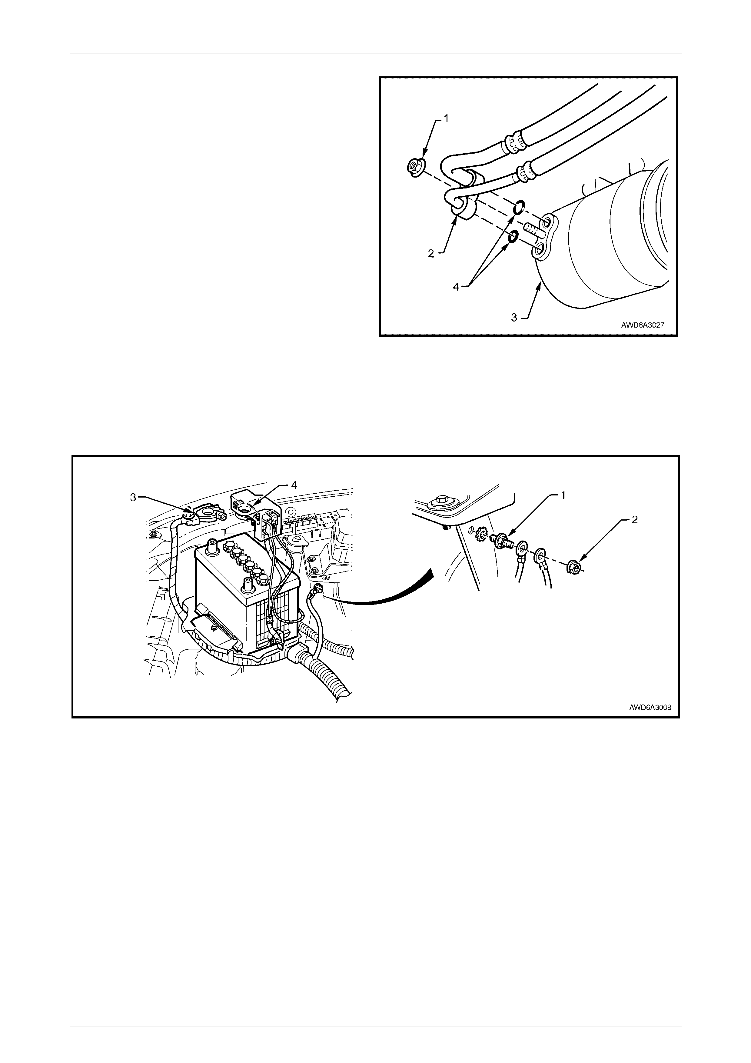
18 Remove the nut (2) securing the battery harness ground terminals to the ABS/TC control module bracket stud (1).
19 Remove the ground terminal (3) at the battery, followed by the positive lead (4).
20 Disconnect battery wiring harness to front body harness connector, X106 attached to the ABS/TC mounting bracket
(not in view). Cut cable ties as required and lay the harness on the engine.
Figure 6A3 – 12
Engine Mechanical – GEN III V8 Engine Page 6A3-12
Page 6A3–12
21 Disconnect the wiring harness connectors from:
1 Mass Air Flow Sensor
2 Air Conditioning Pressure Sensor
3 Main to Powertrain Wiring Harness
Figure 6A3 – 13
22 Referring to Figure 6A3-14, disconnect powertrain wiring harness from the clip (5) in the engine compartment dash
panel.
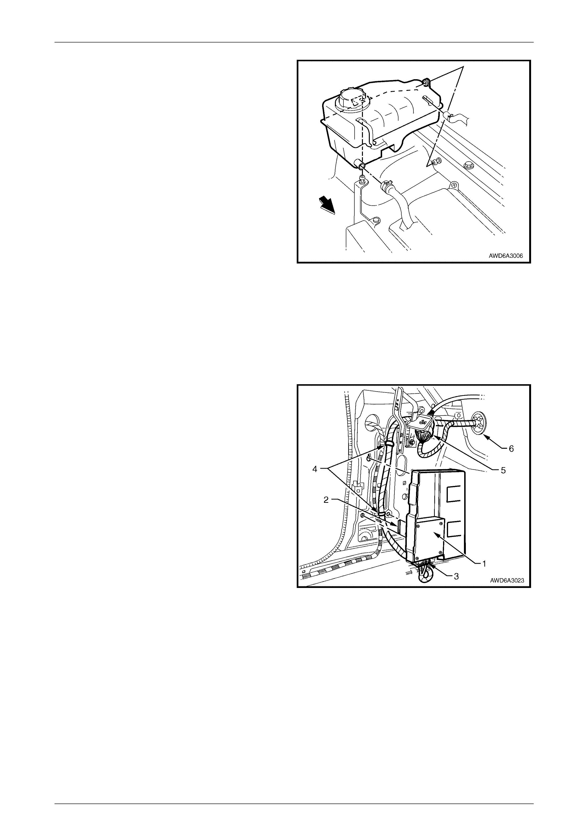
23 Referring to Figure 6A3-14, remove the engine coolant surge tank from its two rubber insulated, retaining pegs.
Turn over and disconnect the surge tank, low coolant switch (‘1’, view A) wiring harness connector, then the
connector from the theft deterrent horn (‘4’, view C).
Figure 6A3 – 14
Engine Mechanical – GEN III V8 Engine Page 6A3-13
Page 6A3–13
24 Loosen hose clamps and remove hoses from the
coolant surge tank, then remove from the engine bay.
25 Remove the three screws securing the upper air
cleaner cover to the lower body, remove the cover and
the filter element.
26 Remove the circular bridging ring at the lower air
cleaner body inlet.
27 Pull the lower air cleaner body upward freeing the
body from the three rubber insulated retaining pegs.
Figure 6A3 – 15
28 Remove the cover from the Powertrain Control Module (PCM), by freeing the locking tang at the front end, then
pivot the cover upward, freeing the two rear locations.
29 Remove both PCM connectors (refer to ‘3’, view B in Figure 6A3-14) in the engine bay, after removing the retaining
screw (bold arrows) from each connector.
30 Temporarily reinstall the PCM cover to stop moisture and dirt entry.
31 Remove the engine wiring harness retaining clip from the engine front lifting bracket.
32 From inside the passenger co mpart men t of the
vehicle, remove the left hand shroud panel trim. For
details, refer Section 1A3 Instru ment Panel and
Console, in the MY 2003 VY and V2 Series Service
Information.
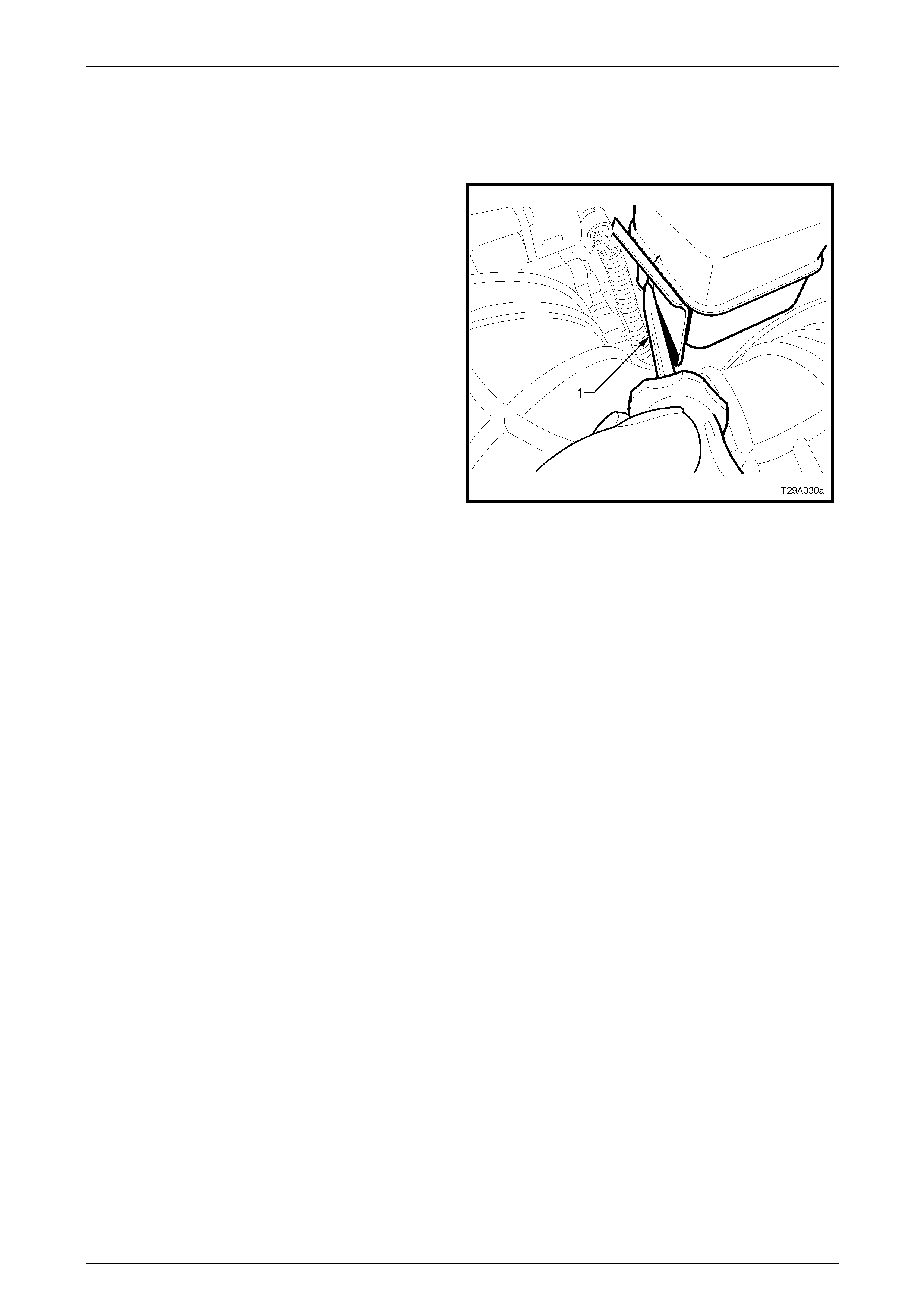
33 Remove the Powertrain Interface Module (PIM) (1)
and carrier, either by using fingers (or a flat bladed
screwdriver) to push on and dislodge the retaining
hook (2), then remove the PIM and carrier.
NOTE
The MY 2004 AWD Wagon is not fitted with a
Throttle Relaxer Module (TRM).
34 Remove the wiring harness connector (3) from the
Powertrain Interface Module (PIM) (1).
35 Cut the wiring harness straps (4) and discard.
36 Disconnect the Powertrain to Main W iring Harness
connector, X206 (5).
Figure 6A3 – 16
37 Release the harness to dash panel grommet (6) and feed the harness and connectors out into the engine bay.
38 Lay the powertrain wiring harness on top of the engine.
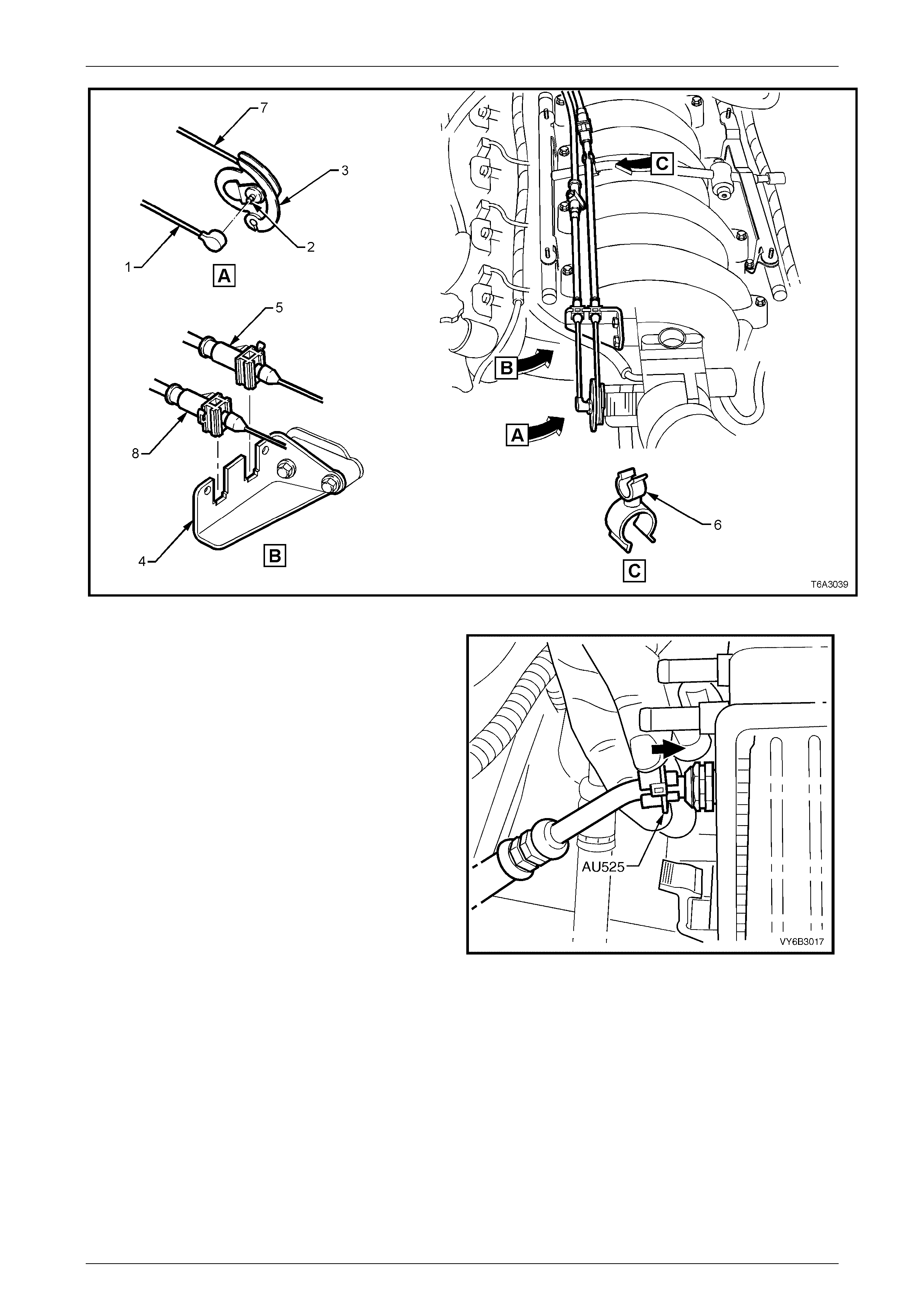
39 Disconnect the cruise control cable (1) (refer Figure 6A3-17) from the stud (2) on the throttle body valve lever (3),
then remove the outer cable (8) from the retainer bracket (4), after releasing the retaining tang with a small
screwdriver.
40 Lift the throttle cable (5) from the clip (6) at the fuel rail crossover pipe, then lift the cable (5) from the retainer
bracket (4), after releasing the retaining tang with a small screwdriver.
41 Remove the inner throttle cable (7) from the throttle body valve lever (3).
42 Set the cable/s to one side.
Engine Mechanical – GEN III V8 Engine Page 6A3-14
Page 6A3–14
Figure 6A3 – 17
43 Disconnect the transmission oil cooler line, quick
connect fittings at the radiator, using Tool No. AU 525.
a Open release tool AU 525, install around the
pipe to be disconnected, then close and clip the
ends together.
b While holding the pipe/flexible hose in with one
hand, push the tool into the connection to
release, then pull back on the pipe.
c Repeat the above process for the lower
pipe/hose assembly.
d Plug all openings in the pipes and oil cooler
quick connect fittings, to prevent transmission
fluid loss and foreign matter entry, then use tie
wire to keep the hoses tethered to the engine.
Figure 6A3 – 18
Engine Mechanical – GEN III V8 Engine Page 6A3-15
Page 6A3–15
44 Use a small screwdriver (or fingers) to release the
security locks (1) from each end of the fuel supply
hose, quick connect fittings (2).
NOTE
Each security lock is fitted to a tether (not
shown) to prevent loss.
Figure 6A3 – 19
45 Using quick connect release Tool No. 7371, open tool
and install over fuel rail line.
46 Close 7371 and pull into fuel rail line quick connect (1)
to release it from the fuel rail, pull back on the quick
connect (1), to remove. Remove the quick connect
release tool from the fuel rail line.
47 Disconnect the vapour line (2) connection to the EVAP
purge control valve (3) and set to one side.
NOTE
Plug all openings to prevent fuel leaking and
dirt/contaminants from entering the fuel system.
Figure 6A3 – 20
48 Disconnect the brake booster and heater control,
vacuum hoses from the rear of the intake manifold.
Figure 6A3 – 21
Engine Mechanical – GEN III V8 Engine Page 6A3-16
Page 6A3–16
NOTE
An alternative procedure to that described in the
next six steps, is that the front driveshaft retaining
nuts are removed and the road wheel nuts
loosened, while the vehicle is still on the ground.
49 Raise the vehicle and support in a safe manner. Refer to Section 0A General Information in this Service
Information, for the location of jacking and support points.
50 Remove the decorative wheel nut caps, then mark the relationship of the road wheel to one of the wheel studs.
51 Loosen, then remove the road wheel attaching nuts, working in a 'star' pattern. Refer to Section 10, Wheels and
Tyres, in the MY 2003 VY and V2 Series Service Information for detailed information. Remove the road wheel.
52 Repeat steps 49 and 50 for the other side road wheel.
NOTE
Steps 49 and 50 are necessary to maintain
component relationships and to avoid brake rotor
distortion and the creation of brake shudder, after
the vehicle is placed back in service.
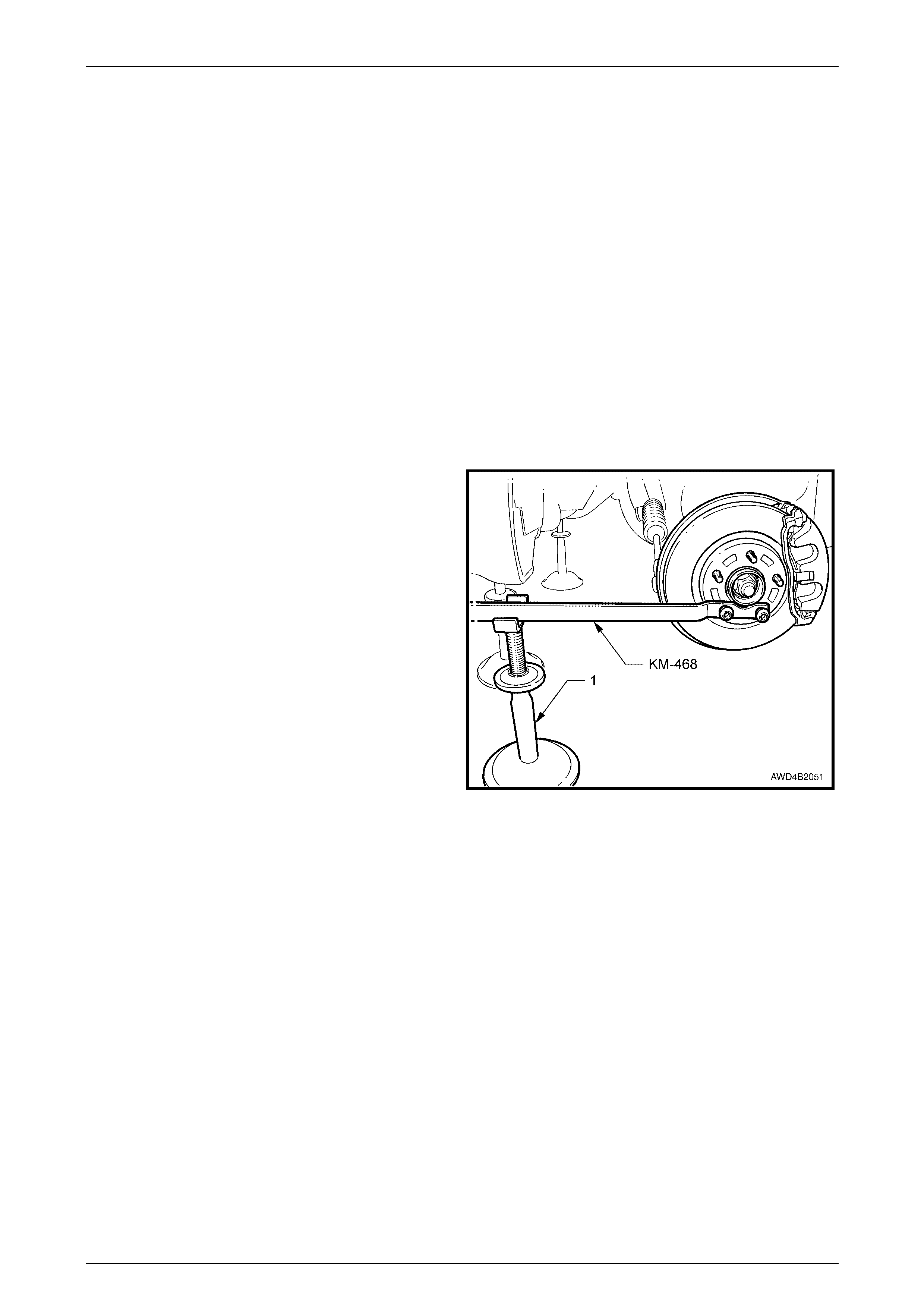
53 Attach holding tool KM-468 to the wheel hub with two
inverted wheel nuts. Support the tool outer end on a
safety stand.
54 Using suitable socket equ ipm e nt, loosen then remove
the 36 mm driveshaft retaining nut and flat washer.
Discard the removed nut.
Figure 6A3 – 22
Under Vehicle
1 Raise vehicle and support in a safe manner. For location of jacking and support points, refer to Section 0A General
Information in this Service Information.
2 If fitted, remove the fasteners securing the oil pan under-tray to the front suspension cradle, then remove the tray
from the vehicle.
3 Remove oil pan drain plug and drain engine oil into a suitable container. Reinstall drain plug once oil has drained
sufficiently.
4 Remove the screws, self tapping screws and scrivets securing the front plastic under tray from the front bumper
and front suspension cradle, then remove the under tray from the vehicle.
5 Remove both nuts securing the engine mounts to the front crossmember cradle, using an 18 mm deep socket and
suitable equipment.
6 Remove the two lowest bolts attaching the automatic transmission to the engine oil pan.
Engine Mechanical – GEN III V8 Engine Page 6A3-17
Page 6A3–17
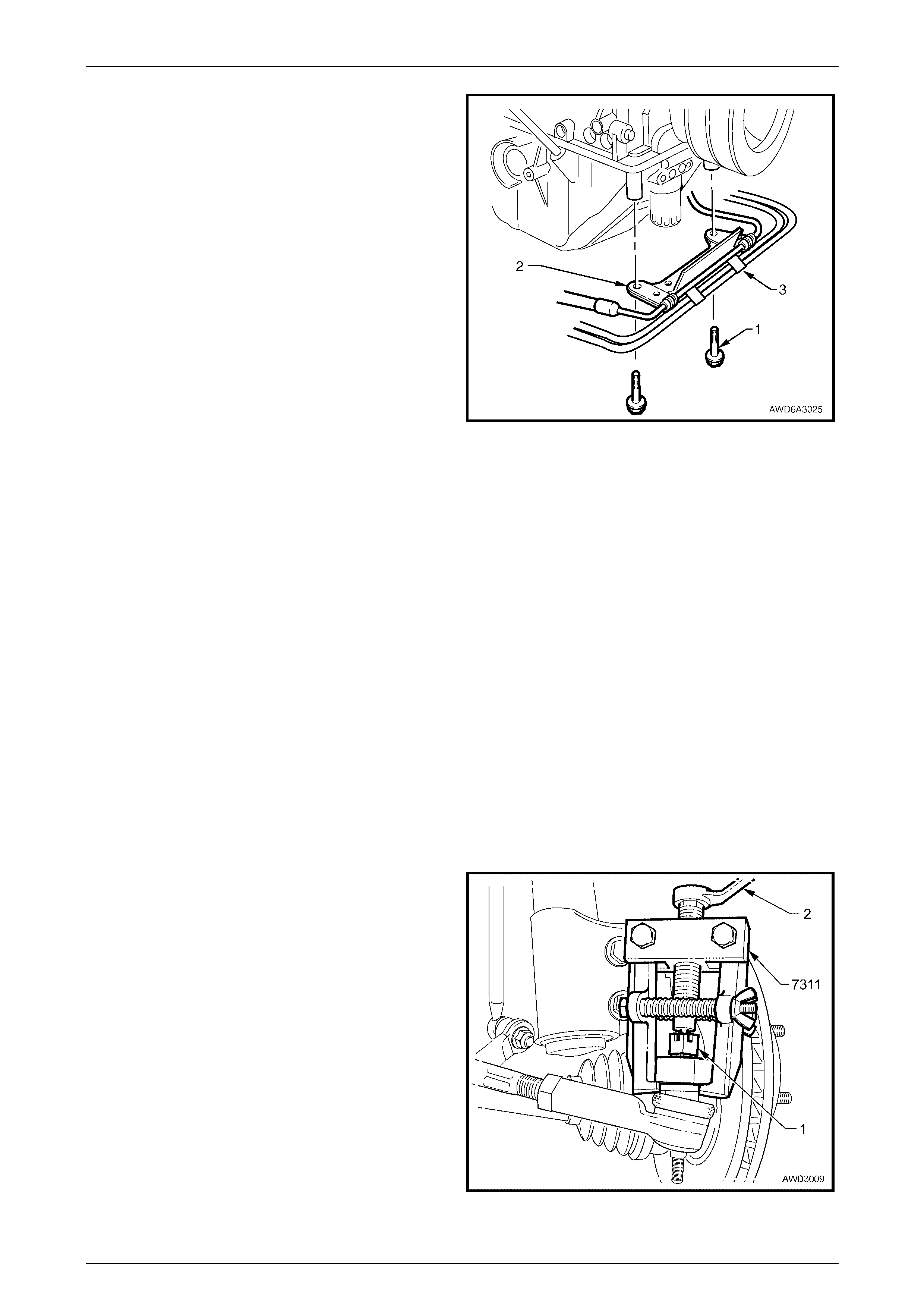
7 Remove the two bracket nuts (not shown) securing the
automatic transmission cooler pipes (3) to the power
steering pipe bracket, then remove the two bolts (1)
holding the bracket (2) to the front of the engine oil
pan.
8 Release the two wiring harness clips from the bracket.
NOTE
Steps 5, 6, 7 and 8 are for convenience, as
removal of these items is easier when the engine
is still in the vehicle.
Figure 6A3 – 23
9 Remove the rear propeller shaft, refer to Section 4C1 Rear Propeller Shaft & Universal Joints in the MY 2004 AWD
Wagon Service Information. This operation involves the removal of the exhaust system, from the rear of the
catalytic conv er t ers.
10 Disconnect the gear shift control cable from the transmission bracket and the selector lever. Refer to Section 7C4
Automatic Transmission – On-Vehicle Servicing, in the MY 2004 AWD Wagon Service Information.
11 Remove both front driveshafts from the vehicle. Refer to 2.4 Driveshaft Assembly, in Section 4B2 Front Final Drive,
Beari ng Ho using & Drivesha fts in the MY 2004 AWD Wagon Service Information. Either plug the seal opening in
the front final drive or drain the lubricant prior to removal of the driveshaft on the left side.
12 After disconnecting both control arm ball joints (removal occurs during step 9), use a suitable length wooden prop
with a 'V' cut out of the outer end, to support the steering knuckle, disc, front hub and strut against the side rail.
Repeat for the other side.
NOTE
As stated in 'General Information' at the
beginning of this service procedure, an
alternative approach would be to lower the struts
with the front suspension cradle after removing
both brake calipers and disconnecting each
wheel speed sensor wiring. This approach also
means that two assistants would be required to
support and guide each strut during removal and
reinstallation operations.
13 Remove the split pin from the steering linkage outer tie
rod end castellated nut (1), then loosen the nut until it
is flush with the end of the tie rod end stud.
14 Install Tool No. 7311 and use a ring spanner (2) to
separate the steering linkage outer tie rod end stud
from the steering knu ck le.
15 Repeat steps 13 and 14 for the other side.
Figure 6A3 – 24
Engine Mechanical – GEN III V8 Engine Page 6A3-18
Page 6A3–18
16 With a backing set spanner holding the stabiliser bar
link inner stud hexagon (1), use a second spanner to
loosen then remove the retaining nut (2).
17 Separate the stabiliser bar link (3) from the stabiliser
bar (4).
18 Repeat steps 16 and 17 for the other side.
Figure 6A3 – 25
19 Loosen power steering cooler line hose clamps (1),
then disconnect both hoses (2). Plug all openings to
prevent excess fluid loss and/or dirt entry.
Figure 6A3 – 26
20 Remove the lower steering coupling cam bolt nut (4)
and discard.
21 Remove the cam bolt (2) from the lower coupling (1),
then push on the coupling to free it from the steering
rack input shaft (3).
Figure 6A3 – 27
Engine Mechanical – GEN III V8 Engine Page 6A3-19
Page 6A3–19
22 Using a felt tipped pen or similar (e.g. Whiteout
correction fluid), mark the position of the rear
crossmember (1) to the underbody side rails.
NOTE
This will assist in realigning the crossmember on
reinstallation.
23 Remove the four bolts (2) attaching the rear
crossmember (1) to the underbody side rails.
24 Remove the three bolts (3) securing the rear
crossmemb er to the transfer c ase mou nt brac ket (not
visible). Remove the crossmember from the vehicle.
NOTE
Support of the transmission is not required at
this time.
Figure 6A3 – 28
25 Remove the nuts securing the exhaust pipe bracket to each catalytic converter, then remove the two bolts securing
the bracket to the transfer case adaptor housing. Remove the bracket.
26 Using a commercially available, hydraulic scissor lift mobile trolley of 750 kg capacity, support the front suspension
cradle.
NOTE
An alternative support would be to use suitable
equipment to support the engine from the two
lifting brackets, from above.
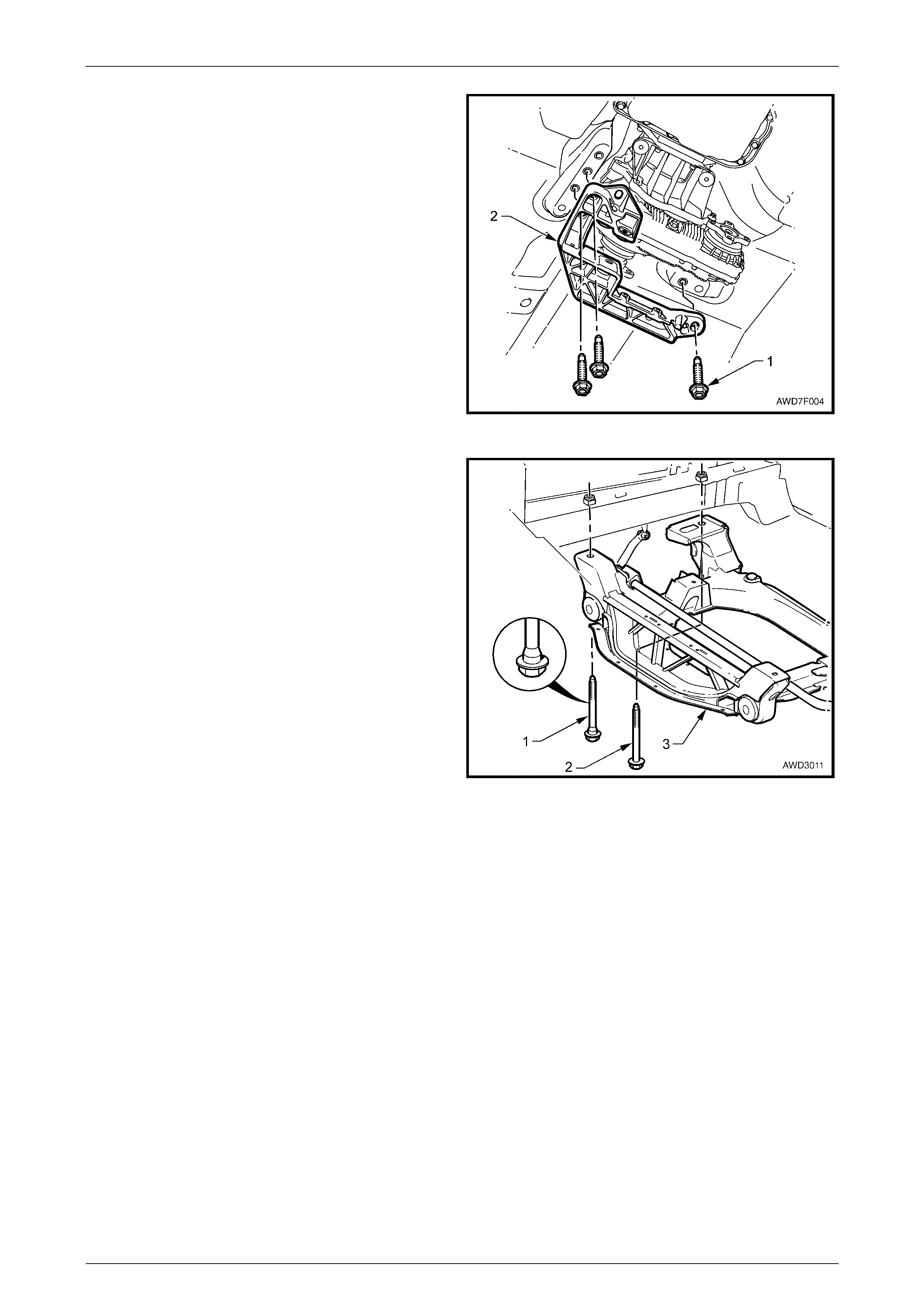
27 With the front suspension cradle and automatic
transmission/transfer case supported, remove the bolt
(1) securing the transfer case rubber mount (2) to the
transfer case rear mounting bracket (3).
Figure 6A3 – 29
Engine Mechanical – GEN III V8 Engine Page 6A3-20
Page 6A3–20
28 Using a felt tipped pen or similar (e.g. Whiteout
correction fluid), mark the position of the transfer case
rear mounting bracket to the vehicle underbody.
NOTE
This will assist in realigning the mounting bracket
on reinstallation.
29 Loosen, then remove the three bolts (1) securing the
transfer case rear mounting bracket (2) to the vehicle
underbody.
30 Remove the transfer case rear mounting bracket (2)
from the vehicle.
Figure 6A3 – 30
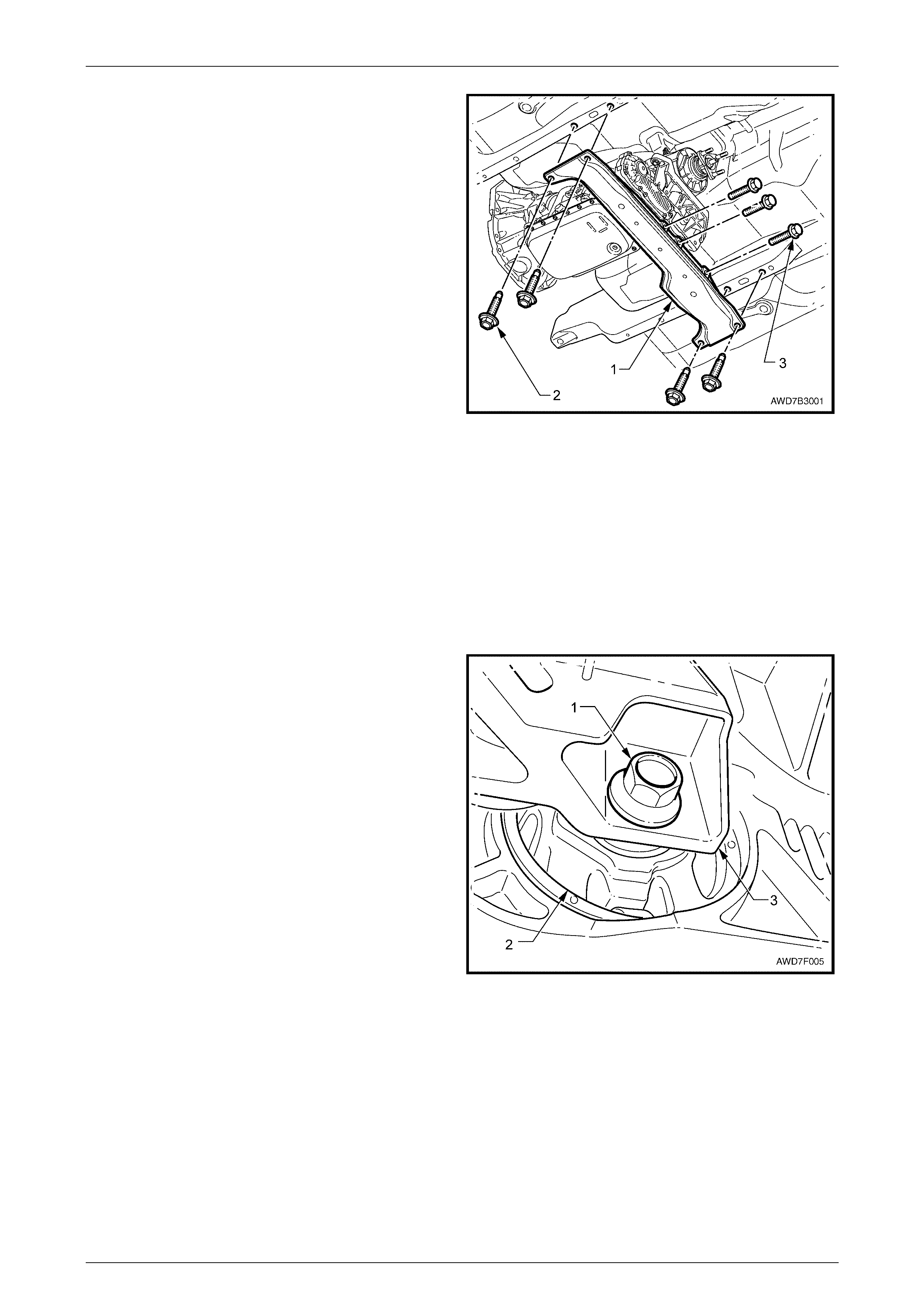
31 Remove the four bolts (1 and 2) securing the
crossmember cradle to the side frame members.
NOTE
The engine is not shown in this view to more
clearly show the front suspension cradle
securing bolt locations.
32 Lower, then remove the crossmember cradle
assembly, engine and transmission/transfer case from
under the vehicle.
Figure 6A3 – 31
Engine Mechanical – GEN III V8 Engine Page 6A3-21
Page 6A3–21
NOTE
For the purposes of this service operation, it is
assumed that the engine is removed for attention
to the oil pan or related components.
33 Using a suitable lever such as a screwdriver (1), gently
lever locking tang back to clear the power steering
fluid reservoir tab, then lift the reservoir up and out of
the retaining bracket.
34 Reset the bracket locking tang back into the original
position.
Figure 6A3 – 32
35 Remove the engine accessory drive belt. Refer to 2.6 Engine Drive Belts - Replace in Section 6A3 Engine
Mechanical - GEN III V8 Engine, in the MY 2003 VY and V2 Series Service Information.
36 Using suitable socket equipment, remove the three bolts securing the power steering pump to the front of the left
side cylinder head, then pull the power steering pump reservoir, pipes and hoses forward to clear the engine.
NOTE
Removing the reservoir and power steering pump
with the hoses/pipes intact means that the power
steering hydraulic system is left intact, with no
bleeding operation required on reinstallation.
37 Disconnect each heated oxygen sensor powertrain wiring harness connector.
38 Remove the exhaust pipe flange nuts on each side, then the remove the exhaust pipes, taking care not to damage
the heated oxygen sensors, in the process.
39 Progressively loosen, then remove the six bolts securing the right side exhaust manifold to the cylinder head,
working from the outside into the centre. Repeat this process for the left side exhaust manifold. Refer to 2.21
Exhaust Manifold, in Section 6A3 Engine Mechanical - GEN III V8 Engine, in the MY 2003 VY and V2 Series
Service Information. This operation also removes the oil level dipstick tube from the oil pan.
NOTE
Removal of the exhaust manifolds is necessary to
gain clear access to the engine mount bracket to
engine block retaining bolts.
Engine Mechanical – GEN III V8 Engine Page 6A3-22
Page 6A3–22
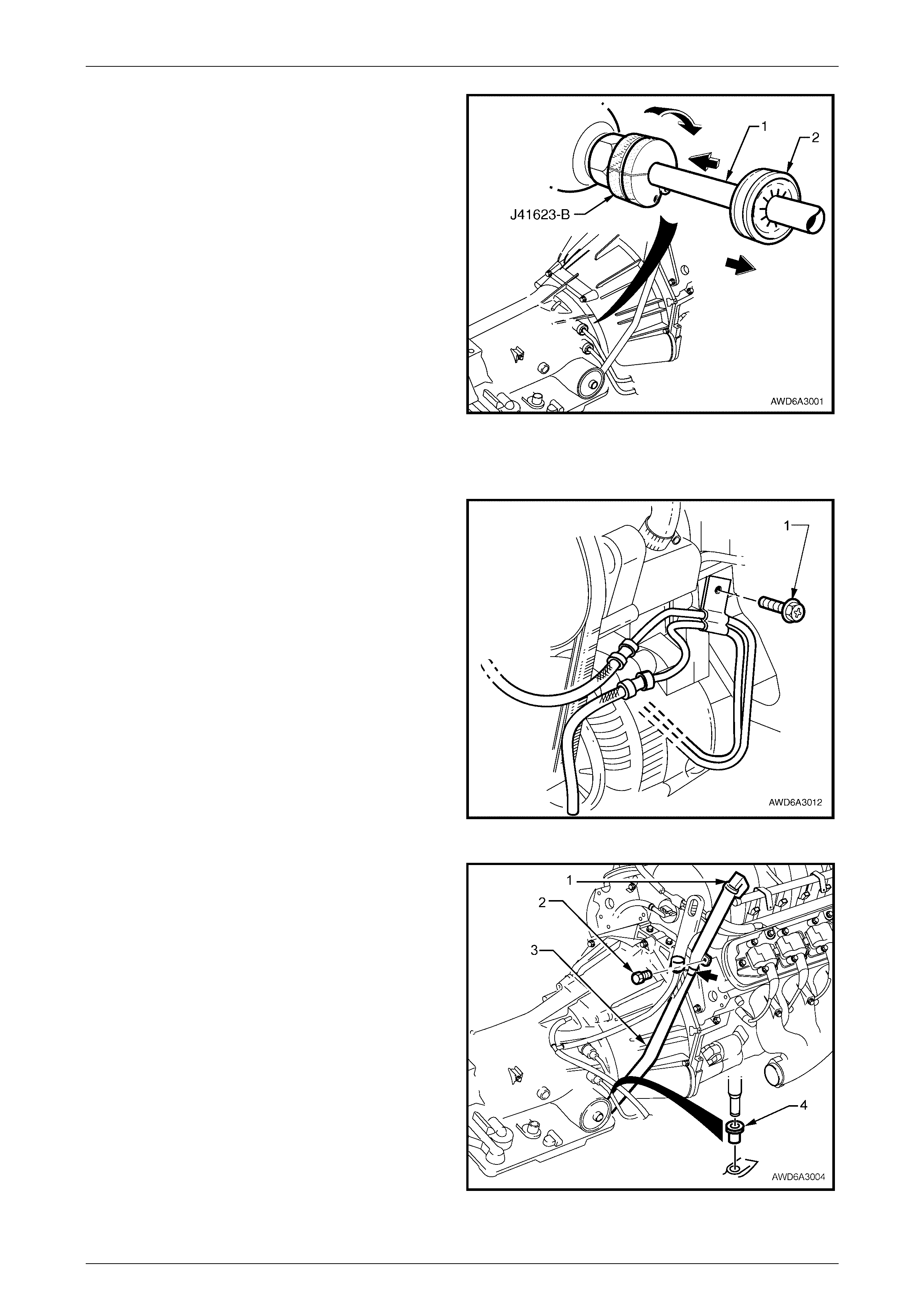
40 Disconnect cooler pipes from the transmission end, as
follows:
a Release the verifier disc (2) by pulling back with
the fingertips, then slide back down the cooler
pipe (1).
b Open cooler line release Tool J-41623-B and slip
over cooler pipe to be disconnected from the
transmission, ahead of the verifier disc (2), as
shown.
c Slide the release tool along the pipe to engage
with the quick-connect fitting.
d While pushing inwards, rotate the tool about one
sixth of a turn to release the spring clip holding
the pipe.
e With the release tool held in this position, pull
back on the cooler pipe to release.
f Repeat this process with the remaining pipe and
quick-conn ect fitt ing.
Figure 6A3 – 33
g Plug all openings to prevent excess fluid loss and/or foreign matter entry.
41 Remove the cooling pipe bracket (1) securing bolt,
then remove the cooler pipes.
Figure 6A3 – 34
42 Release the dipstick lock down lever (1) and remove
the transmission dipstick.
43 Remove the bolt (2) securing transmission filler tube to
the right hand cylinder head.
44 Release the transmission breather tube (3) from the
dipstick bracket (arrow).
45 Using a twisting/pulling motion, remove filler tube (3)
from transmission case seal (4). Set the filler tube to
one side.
46 Plug the filler tube opening in the automatic
transmission.
Figure 6A3 – 35
Engine Mechanical – GEN III V8 Engine Page 6A3-23
Page 6A3–23
47 Disconnect the transfer case breather tube from the wiring harness clips.
48 Remove the powertrain wiring harness connectors and ground connections from the engine and transmission
assembly, then carefully set the wiring harness to one side.
49 Unclip the starter motor heat shield and set to one side.
50 Disconnect the battery positive lead and the solenoid connector from the starter motor.
51 Remove the two bolts securing the starter motor, then set the starter motor to one side.
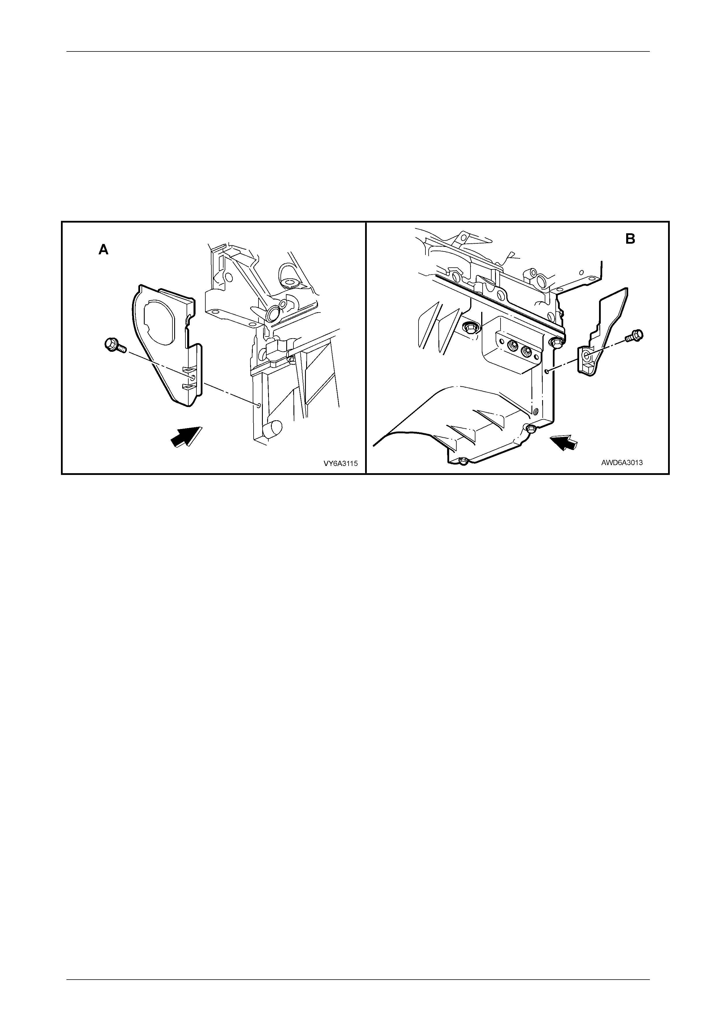
52 Remove the close-out cover retaining screw, then remove the cover. Referring to Figure 6A3-36, view 'A' shows the
right side close-out cover, while view 'B shows the left.
Figure 6A3-36
53 Remove the three bolts securing the torque converter to the engine flexplate, using the right side close-out cover
opening for access to the bolts.
54 Remove the torque converter housing to engine block and oil pan bolts, then slide (or lift) the transmission and
transfer case free from the rear of the engine.
55 Using suitable lifting equipment fitted to the engine lift brackets, lift the engine clear from the front suspension
crossmember cradle.
56 When clear, remove the four bolts securing the right side engine mount bracket to the engine block, then set the
bracket and hydraulic mount, together with the heat shield, to one side.
57 Repeat step 55 for the left side engine mount bracket.
58 Remove the four bolts securing the front final drive to the engine oil pan, then remove the front final drive
assembly, complete with the intermediate shaft and set to one side.
59 Remove the three bolts securing the driveshaft bearing housing, remove the housing assembly and set to one side.
60 Mount the engine in the stand, designed for the purpose, Tool No. AU 591 and AU 591-1, using the four engine
mount bracket bolts from each side, to secure the stand brackets to the side of the engine block.

Engine Mechanical – GEN III V8 Engine Page 6A3-24
Page 6A3–24
Reinstall, Set-up and Testing
Reinstallation of the engine assembly is the reverse of removal procedures, noting the following points:
1 Ensure that all fasteners are replaced or cleaned with thread sealant reapplied as required (as stated in the text or
refer to 5 Specifications, in this Section), and tightene d to the correct tor que spe cif ic atio ns, r efer to 6 Torque
Specifications, at the end of this Section.
2 Use only the specified engine lubricant type and quantity. It is recommended that a fluorescent oil dye, such as that
contained in J 28481-B, be added to assist in any future oil leak diagnosis.
3 Fill the cooling system with the proper quantity and grade of coolant. Refer Section 6B3 Engine Cooling –
GEN III V8 Engine, in the MY 2003 VY and V2 Series Service Information. Also, refer to Environmental Issues
in 1.2 Service Notes, in this Section.
4 Check transmission fluid level, topping up as required, using the specified lubricant. Refer to Section 7C4
Automatic Transmission - On-Vehicle Servicing, in the MY 2003 VY and V2 Series Service Information.
5 Disable the ignition system. Refer to 2.5 Compression Check, in Section 6A3 Engine Mechanical - GEN III V8
Engine, in the MY 2003 VY and V2 Series Service Information.
6 Crank the engine several times. Listen for any unusual noises or evidence that parts are binding.
7 Enable the ignition system, start the engine and listen for unusual noises.
8 Check the vehicle oil pressure gauge or oil pressure warning lamp and confirm that the engine has acceptable oil
pressure. If necessary, install an oil pressure gauge and measure the engine oil pressure. Refer to 2.4 Engine Oil
Pressure Check, in Section 6A3 Engine Mechanical - GEN III V8 Engine, in the MY 2003 VY and V2 Series Service
Information.
9 Run the engine speed at about 1,000 rpm until the engine has reached normal operating temperature.
10 Listen for sticking lifters and other unusual noises.
11 Check for oil, fuel, coolant and exhaust leaks while the engine is running, correcting as required.
12 Perform a final inspection for the proper engine oil and coolant levels.
13 Check the engine hood alignment (if removed).
Engine Mechanical – GEN III V8 Engine Page 6A3-25
Page 6A3–25
3.2 Oil Pan
LT Section No. – 00-275
Remove
1 Remove the engine from the vehicle and mount in an engine stand such as Tool No. AU 591. Refer to 3.1 Engine
Assembly, Remove, in this Section for details.
NOTE
This procedure will have removed the front final
drive and the driveshaft support bearing
assembly from the engine oil p an.
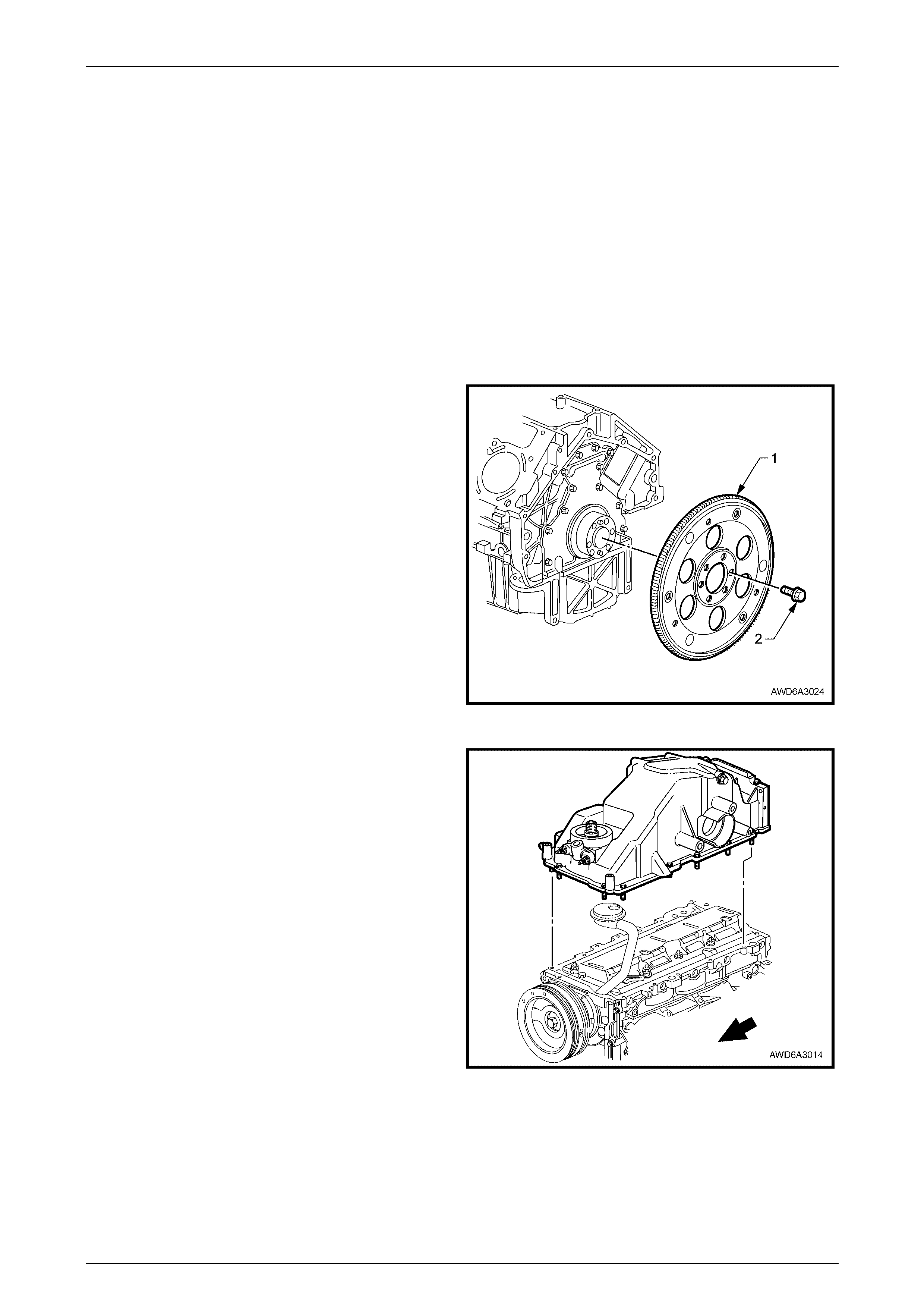
2 Mark the relationship of the flexplate (1) to the
crankshaft, using a felt tipped pen or similar.
3 Gradually loosen then remove the flexplate to
crankshaft retaining bolts (2). Discard the bolts after
removal as they must be replaced on reinstallation.
4 Remove the flexplate (1) from the end of the engine
crankshaft.
NOTE
Removal of the flexplate is necessary to remove
the engine oil pan.
Figure 6A3 – 37
5 Invert the engine assembly.
6 Remove the engine oil pan bolts loosening gradually
from the ends and working towards the centre.
7 Use a rubber mallet to strike the sides of the engine oil
pan, to dislodge the seal.
8 Lift the engine oil pan clear of the engine block, then
move oil pan to the rear, to clear the oil pick-up pipe
and screen.
9 Lift the engine oil pan clear from the engine block.
Figure 6A3 – 38
Engine Mechanical – GEN III V8 Engine Page 6A3-26
Page 6A3–26
Disassemble
NOTE
The original oil pan gasket is retained and
aligned to the oil pan by pop rivets (2). When
reinstalling a new gasket as a service
replacement, it is not necessary to install new oil
pan gask et rivets.
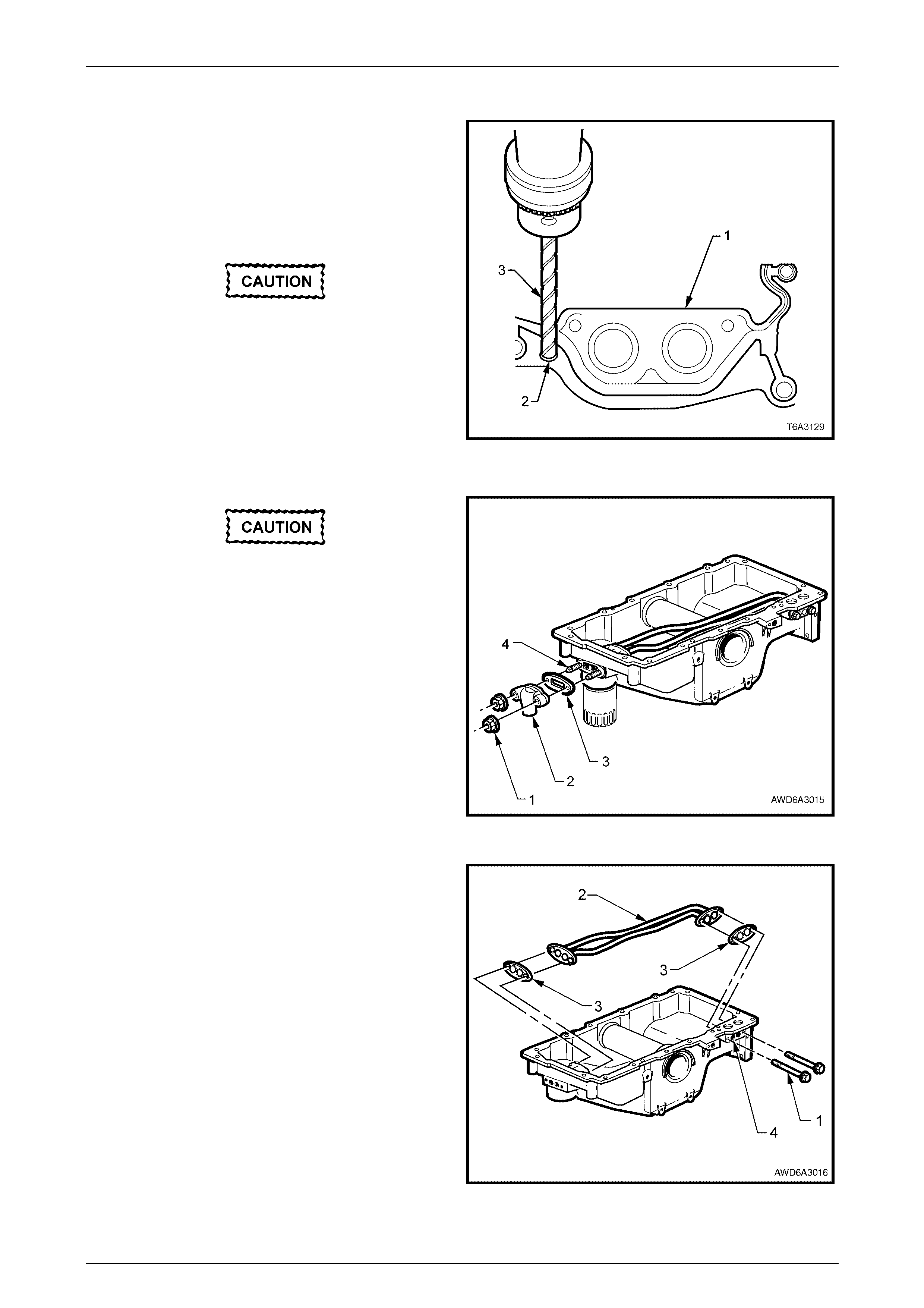
Plug all openings before removal of the
original gasket rivets, to prevent metal
shavings or other foreign material from
entering the oil passages in the oil pan.
1 Use a sharp twist drill (3) to drill out each of the
retaining rivet heads (2).
2 Remove the oil pan gasket (1) from the oil pan.
3 Discard the gasket and rivets.
Figure 6A3 – 39
If removal of the oil transfer cover nuts (1) is
required while the oil pan is still installed
(e.g. during the fitment of an external oil
cooler), hold the studs (4) with an E5 Torx
socket to prevent them from being loosened
or removed. If removed, then the internal
transfer tube gasket can become dislodged.
4 Remove the oil transfer cover nuts (1), cover (2) and
gasket (3) from the front of the oil pan. Discard the
removed gasket (3).
5 Remove both oil filter transfer tube studs (4), using an
E5 Torx bit socket
NOTE
Removal of the transfer tubes without removing
the two studs, is not possib le.
Figure 6A3 – 40
6 Remove the two oil filter transfer tube bolts (1).
7. Remove the oil filter transfer tubes (2) and discard the
gaskets (3).
8. If required, use an Allen key socket to remove the oil
gallery plugs (4).
Figure 6A3 – 41
Engine Mechanical – GEN III V8 Engine Page 6A3-27
Page 6A3–27
Clean and Inspect
1 Clean the oil pan in a suitable solvent. Ensure that all oil passages and recesses are thoroughly cleaned.
2 Clean the oil pan gasket surfaces, using a plastic scraper to avoid scratching or damaging the machined surfaces.
Wear safety glasses to avoid eye injury.
3 Dry the oil pan with compressed air.
4 Inspect the oil pan for the follow ing:
a Gasket sealing surfa ce s for exces siv e scra tch es or gougin g.
b Oil pan drain plug and threaded drain hole for damaged threads. The drain plug O-ring seal may be reused if
not cut or damaged.
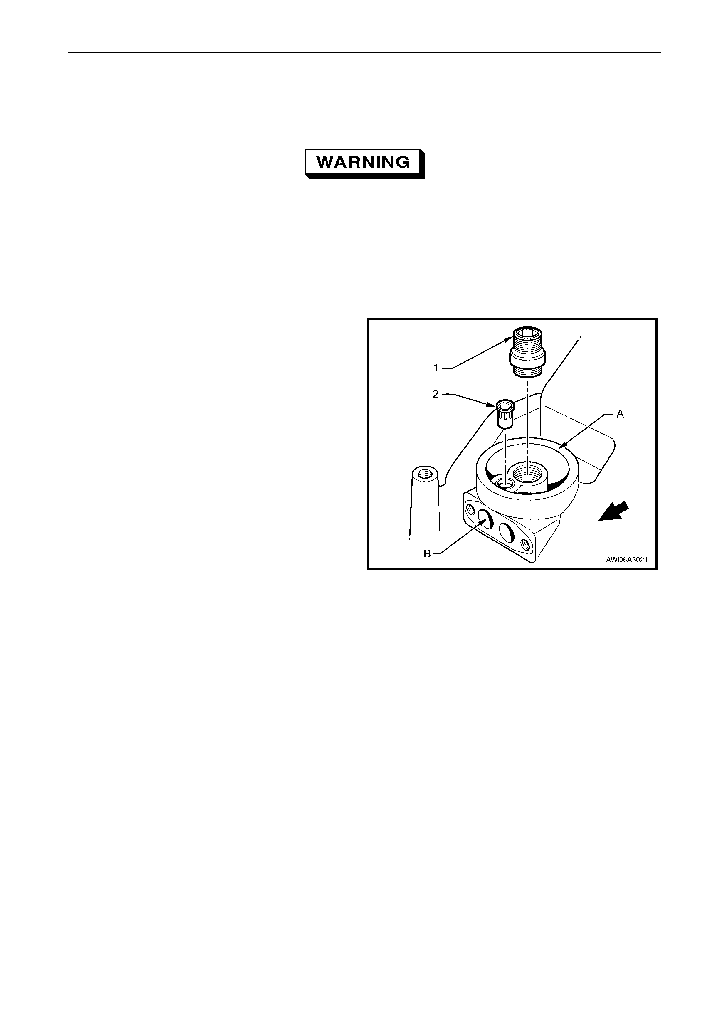
c Oil filter sealing surface 'A' for scratches or
gouging.
d Oil filter adaptor (1) for a loose fit or damaged
threads.
e Oil passages for restrictions.
f Oil filter bypass valve (2) in the oil filter flange for
proper operation Lightly push the bypass valve
into the bore. The valve spring should reseat the
valve to the proper position.
g Check that the cup plug installed in drilling 'B' is
in place and secure.
5. Inspect the oil transfer tube for damage or restri ctio ns.
Figure 6A3 – 42
6 Inspect the flexplate for the following:
a Damaged ring gear teeth.
b Stress cracks around the crankshaft bolt hole locations.
c Welded areas that retain the ring gear to the flexplate.
Engine Mechanical – GEN III V8 Engine Page 6A3-28
Page 6A3–28
Reassemble
1 If removed, apply thread lock compound such as
Loctite 242 (or equivalent) to the cleaned threads of
the oil gallery plugs (4).
2 Use an Allen key socket and tighten the oil gallery
plugs to the correct torque specification.
Oil gallery plug
torque specific atio n ..............................................25 Nm
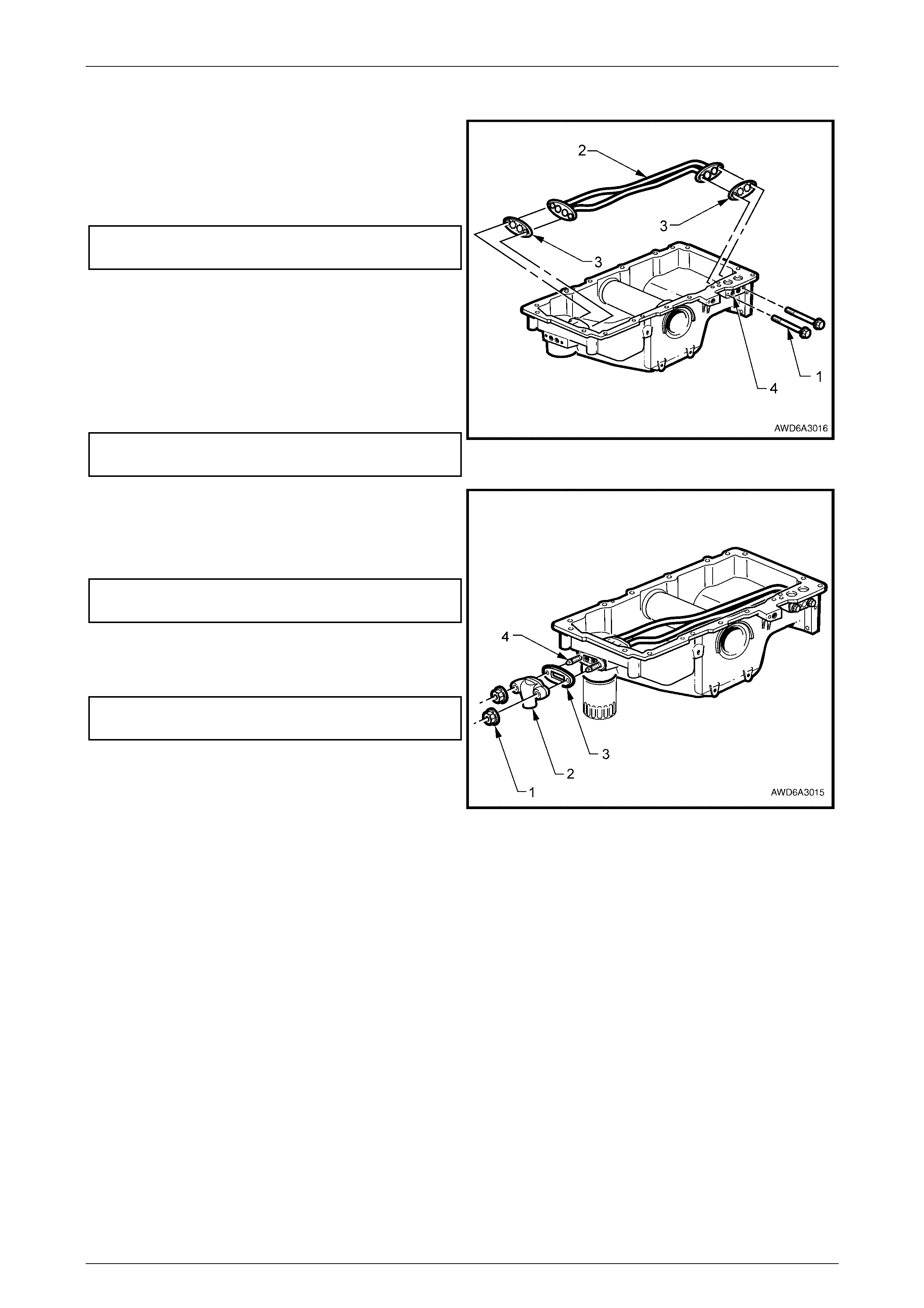
3 Using NEW gaskets (3), install the oil filter transfer
tubes (2) to the oil pan.
4 Apply thread lock compound such as Loctite 242 (or
equivalent) to the cleaned threads of the oil transfer
tube bolts (1) and studs.
5 Install the two bolts (1) and studs, tightening to the
correct torque specification.
Oil filter transfer tube bolt
and studs torque specif ic atio n..............................12 Nm
Figure 6A3 – 43
6 Install NEW oil pan transfer cover gasket (3), cover (2)
and nuts (1).
7 While holding the studs (4) with an E5 Torx socket,
tighten the nuts to the correct torque specification.
Oil transfer cover nut
torque specific atio n ..............................................12 Nm
8 If removed, install the oil filter adaptor and tighten to
the correct torque specification.
Refer to Figure 6A3- 42.
Oil filter adaptor
torque specific atio n ..............................................55 Nm
9 If required, install a NEW oil filter bypass valve, using
a suitable size socket and hammer to fully seat the
valve in the oil filter flange of the oil pan.
Figure 6A3 – 44
Engine Mechanical – GEN III V8 Engine Page 6A3-29
Page 6A3–29
Reinstall
The alignment of the structural oil pan is
critical. The rear bolt hole locations of the oil
pan provide mounting points for the
transmission torque converter housing. To
ensure the rigidity of the powertrain and
correct transmission alignment, it is
important that the rear of the engine block
and the rear of the oil pan are flush. The rear
of the oil pan must NEVER protrude beyond
the engine block and transmission torque
converter housing plane.
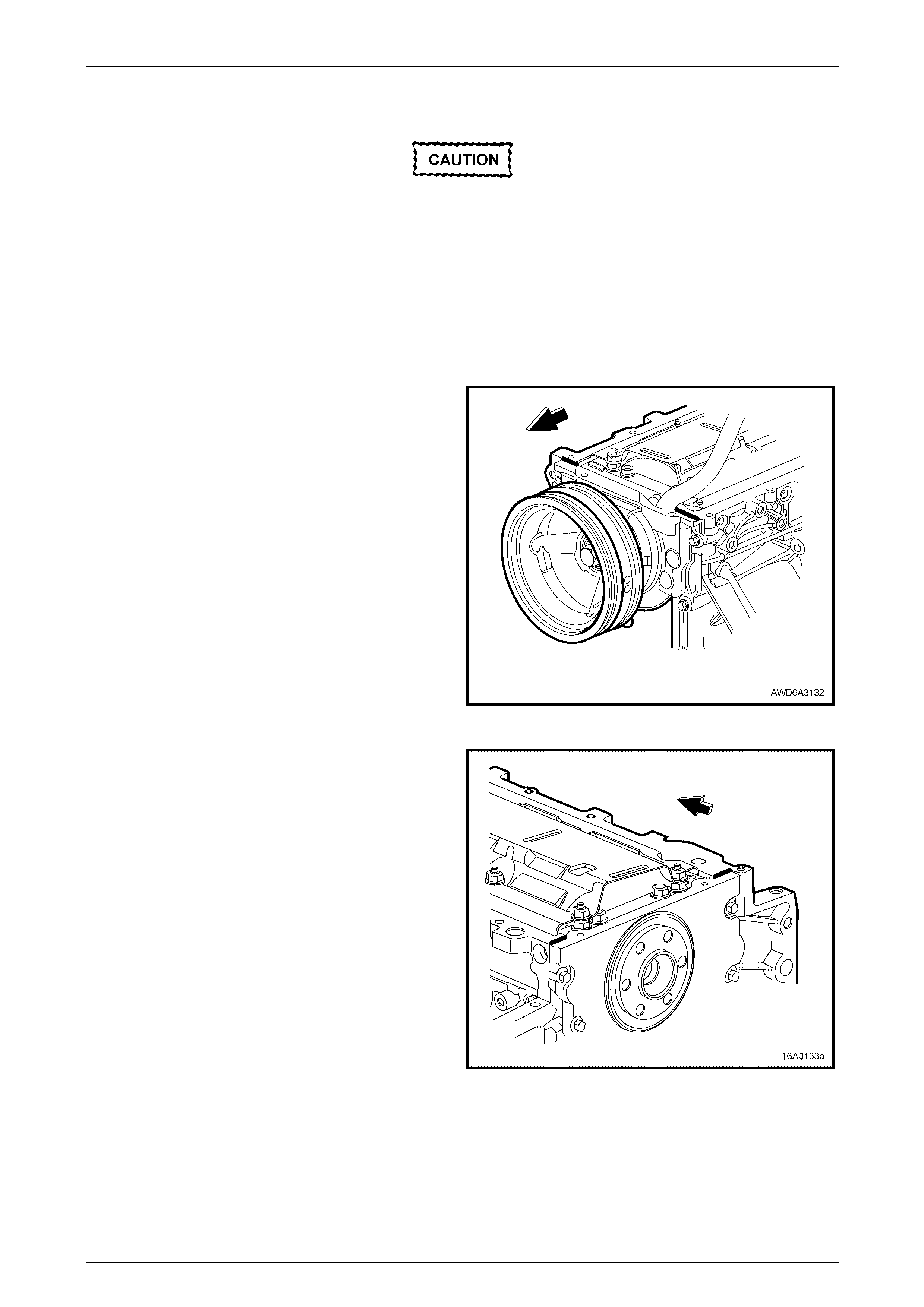
1 Apply a 5 mm wide bead of sealant such as Loctite
565 or equivalent, 20 mm long to the engine block, as
shown. Apply the sealant directly onto the tabs of the
front cover gasket that protrude into the oil pan
surface.
Figure 6A3 – 45
2 Apply a 5 mm wide bead of sealant such as Loctite
565 or equivalent, 20 mm long, to the engine block, as
shown. Apply the sealant directly onto the tabs of the
rear cover gasket that protrude into the oil pan
surface.
Figure 6A3 – 46
Engine Mechanical – GEN III V8 Engine Page 6A3-30
Page 6A3–30
3 Install a NEW oil pan gasket to the oil pan.
NOTE
• Be sure to align the oil gallery passages in
the oil pan and engine block properly with the
oil pan gask et.
• It is not necessary to rivet the NEW gasket to
the oil pan.
4 Install the oil pan bolts to the pan and through the
gasket. Install the oil pan, gasket and bolts to the
engine block. Tighten bolts finger tight. Do not over-
tighten.
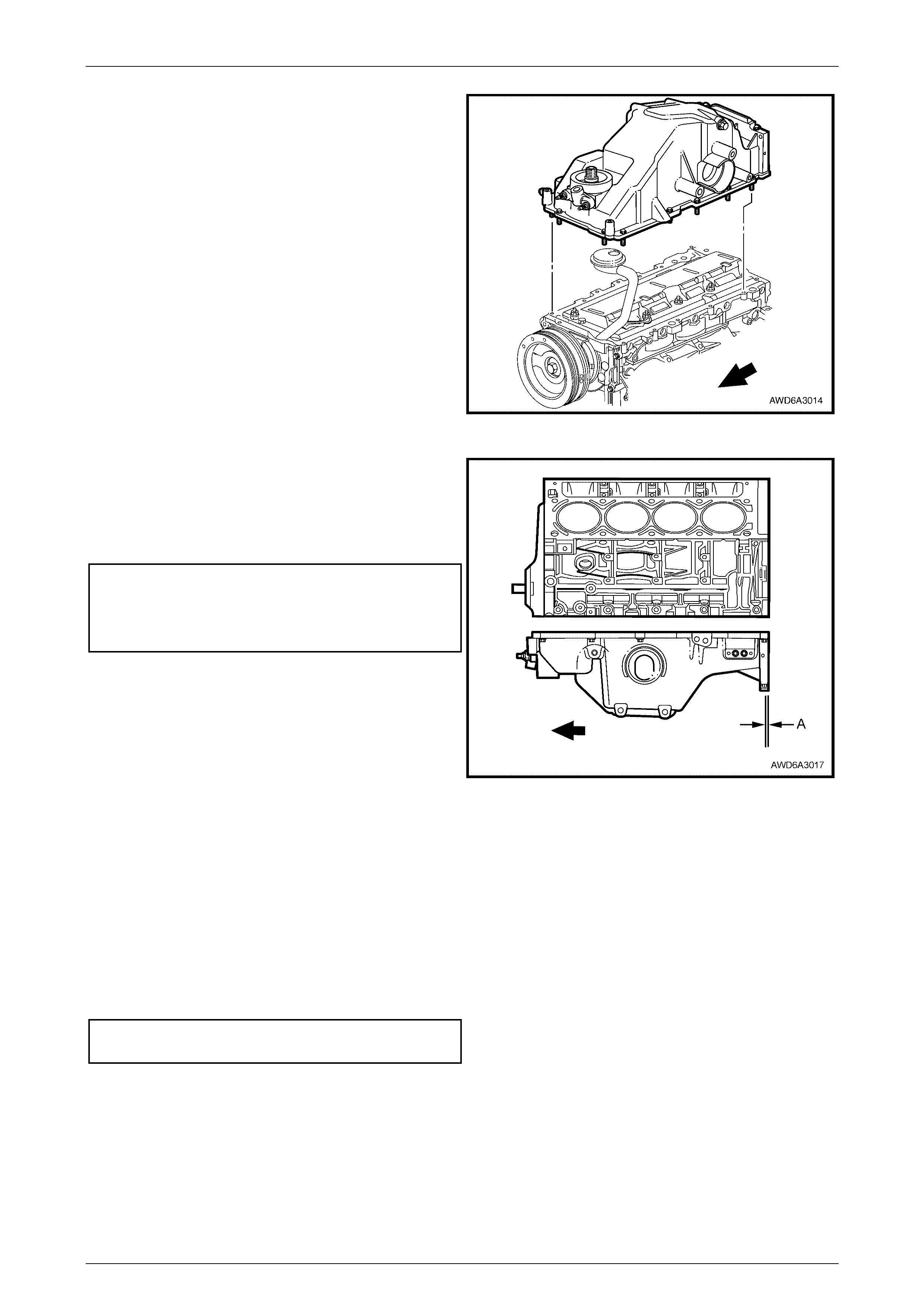
5 Place a straight edge across the rear of the engine
block and the rear of the oil pan at the transmission
torque converter hous ing mou nting surfac es.
Figure 6A3 – 47
6 Align the oil pan until the rear of engine block and rear
of oil pan are flush or even.
7 Install the oil pan to front cover bolts and the oil pan to
rear cover bolts, tightening each to the correct torque
specification.
Oil pan to front cover bolt
torque specific atio n ..............................................25 Nm
Oil pan to rear cover bolt
torque specific atio n ..............................................12 Nm
NOTE
This preliminary step is needed to avoid oil pan
‘creep’ and create a misalignment condition.
8 Place a straight edge across the rear of the engine
block and rear of oil pan at the transmission torque
converter housing mounting surfaces.
Figure 6A3 – 48
9 Insert a feeler gauge between the straight edge and the oil pan transmission torque converter housing mounting
surface and check to make sure that the oil pan is flush to no more than a 0.25 mm gap between the pan and
straight edge (dimension ‘A’, in Figure 6A3-48).
NOTE
The rear of the oil pan must NEVER protrude
beyond the engine block and transmission torque
converter housing mounting surfaces.
10 Install remaining oil pan to cylinder block bolts and tighten to the correct torque specification.
Oil pan to cylinder block bolt
torque specific atio n ..............................................25 Nm
11 If the oil pan alignment is not within specification, the oil pan must be removed and the above procedure repeated.
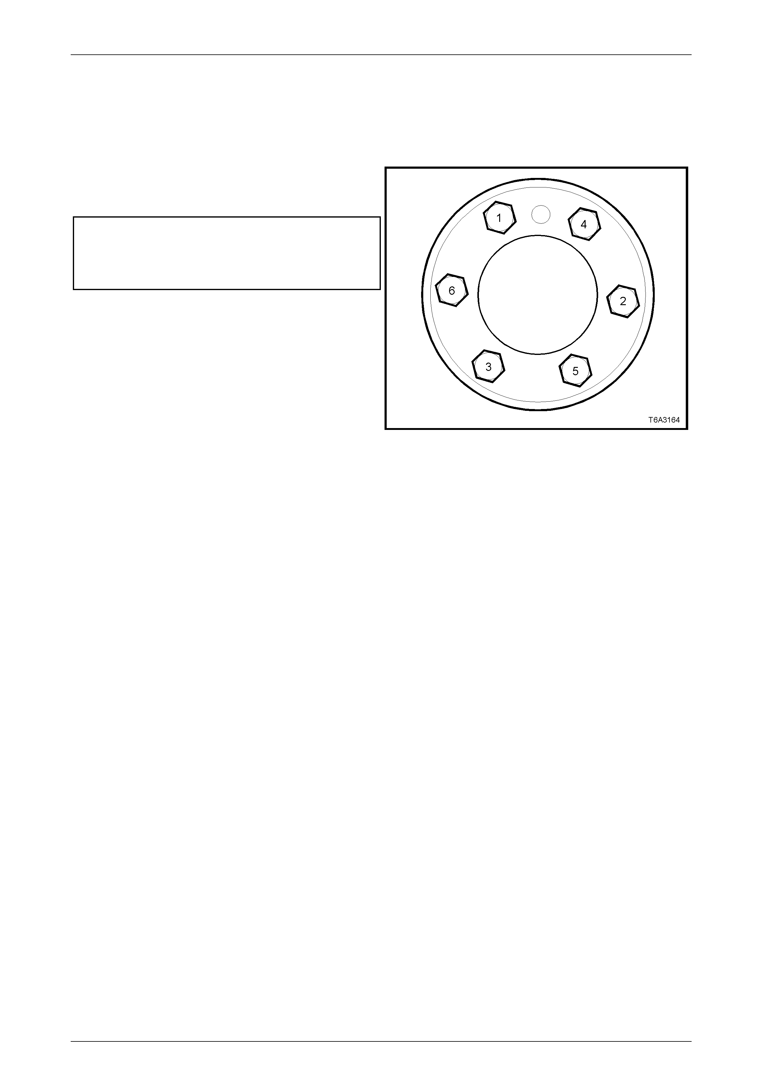
12. Reinstall the flywheel/flexplate, aligning the scribed marks on the crankshaft and flywheel/flexplate.
13. Loosely install NEW flexplate bolts, tightening in sequence to an initial torque specification of 20 Nm. Refer to
Figure 6A3-45.
14. Install ring gear holding Tool No. J 42386-A, using the two starter motor bolts. Tighten both bolts to 50 Nm.
Engine Mechanical – GEN III V8 Engine Page 6A3-31
Page 6A3–31
NOTE
Ensure that the teeth of the holding tool engage
correctly with the ring gear teeth, before
tightening the fasteners.
15 Continue to tighten the flexplate bolts in the sequence
shown, in two additional stages and to the correct
torque specif ication.
Flexplate bolt
torque specification ...................Stage 1:............ 20 Nm
Stage 2:............. 50 Nm
Stage 3:........... 100 Nm
16 Reinstall transmission/transfer case assemblies. Refer
to Section 7C4 Automatic Transmission, in th e
MY 2004 AWD Wagon Service Information.
Figure 6A3 – 49
17 Reinstall the engine. Refer to 3.1 Engine Assembly – Reinstall, Set-up and Testing, in this Section.
Engine Mechanical – GEN III V8 Engine Page 6A3-32
Page 6A3–32
3.3 Oil Pump Pick-up Tube, Screen and Oil
Deflector
LT Section No. – 00-251
Remove
1 Remove the engine from the vehicle and mount in an engine stand such as Tool No. AU 591. Refer to
3.1 Engine Assembly, Remove, in this Section for details.
NOTE
This procedure will have removed the front final
drive and the driveshaft support bearing
assembly from the engine oil p an.
2 Remove the oil pan. Refer to 3.2 Oil Pan, Remove, in this Section.
NOTE
If work also needs to be done on the oil pump,
then the harmonic balancer and front cover will
need to be removed. Refer to 2.24 Harmonic
Balancer – Remove and 3.4 Engine Front Cover
– Remove, in Section 6A3 Engine Mechanical –
GEN III V8 Engine, in the MY 2003 VY and V2
Series Service Information.
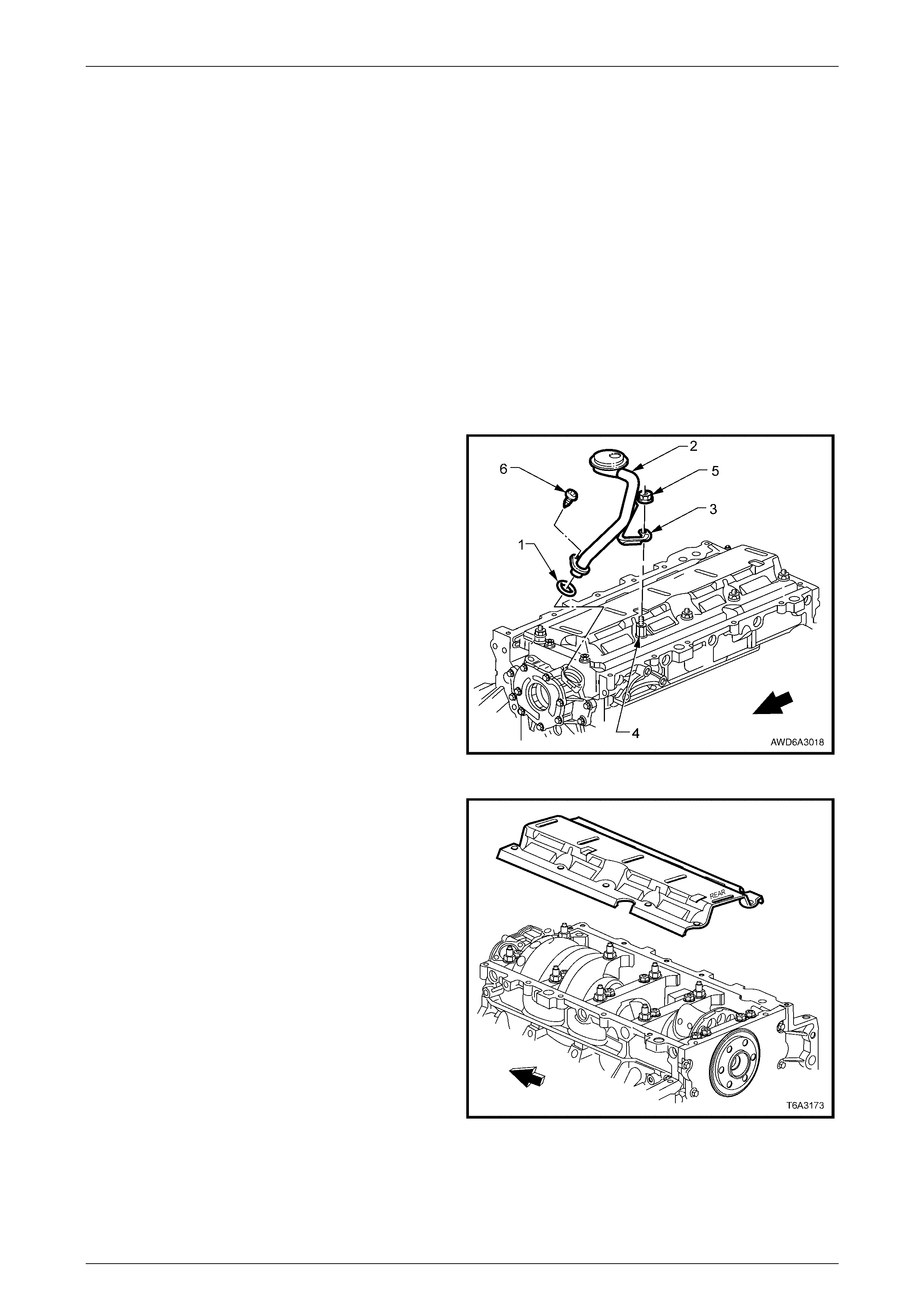
3. While holding the crankshaft oil deflector stud
extension (4) with a set spanner, remove the oil pump
pick-up tube and screen (2), bracket nut (5) from the
crankshaft oil deflector stud extension.
4 Remove the oil pump pick-up tube and screen (2)
retaining screw (6) from the oil pump body.
5. Twist and pull on oil pump pick-up tube to remove
from the oil pump bore. Discard the O-ring (1).
Figure 6A3 – 50
6 Remove the crankshaft oil deflector stud extension,
then the remaining crankshaft oil deflec tor nuts.
7. Remove the crankshaft oil deflector, noting that the
cover is stamped ‘REAR’ to assist in correct
installation.
Figure 6A3 – 51
Engine Mechanical – GEN III V8 Engine Page 6A3-33
Page 6A3–33
Clean and Inspect
Wear safety glasses to avoid eye injury.
1 Clean the oil deflector, oil pick-up pipe and screen, with a suitable solvent and blow dry.
2 Replace the oil pump pick-up and screen and pipe assembly, if either of the followi ng conditions is evident:
a Inspect the oil pump pick-up screen for clogging with debris or restriction.
b Inspect the screen mesh for damage such as broken or loose strands.
3 Check the deflector for distortion or damage, replacing as required.
4 Check the main bearing cap bolt threads for damage. Reclaim or replace the studs as required.
Reinstall
1 Reinstall the crankshaft oil deflector, noting that the
‘REAR’ stamping on the deflector is located at the rear
of the engine.
2 Install all the crankshaft oil deflector nuts to the main
bearing cap studs, except the nut that secures the oil
pick-up pipe and screen. This location has the stud
extension fitted to the main bearing cap stud. Tighten
the nuts and the extension to the correct torque
specification.
Crankcase oil deflector nut
torque specific atio n ..............................................25 Nm
Crankcase oil deflector stud
extension torque specification..............................25 Nm
Figure 6A3 – 52
3 Lubricate a NEW oil pump pick-up tube O-ring (1) with
clean engine oil and install onto the oil pump pick-up
tube (2).
4 Fully install the pick-up tube (2) into the oil pump
housing, aligning the support bracket (3) with the main
bearing cap stud extension (4).
5 Check that the pick-up tube is fully installed, then
reinstall the pick-up tube screw (6) and tighten to the
correct torque specification.
Oil pump pick-up tube
screw torque specification....................................12 Nm
6 Reinstall the remaining nut (5) to the main bearing cap
stud extension (4) then, while holding the stud
extension with a set spanner, tighten the nut (5) to the
correct torque specification.
Crankcase oil deflector nut
torque specific atio n ..............................................25 Nm
Figure 6A3 – 53
7. Reinstall the oil pan, refer to 3.2 Oil Pan – Reinstall, in this Section.

Engine Mechanical – GEN III V8 Engine Page 6A3-34
Page 6A3–34
8. If removed, reinstall the front cover, refer to 3.4 Engine Front Cover – Reinstall and 2.24 Harmonic Balancer –
Reinstall, in Section 6A3 Engine Mechanical - GEN III V8 Engine, in the MY 2003 VY and V2 Series Service
Information.
9 Reinstall the engine. Refer to 3.1 Engine Assembly, Reinstall, Set-up and Testing, in this Section.


Engine Mechanical – GEN III V8 Engine Page 6A3-36
Page 6A3–36
5 Specifications
NOTE
Only those specifications relative to the engine
operations described in this Section are included
here. For all remaining specifications, refer to
5 Specifications, in Section 6A3 Engine
Mechanical – GEN III V8 Engine, in the MY 2003
VY and V2 Series Service Information.
Lubrication System
Oil Capacity (with Oil Filter Change)...........................................................................8.0 litres
Oil Capacity (without Oil Filter Change)......................................................................7.6 litres
Oil Type................................................................................10W – 30 SJ GF2 (Service Refill)
Oil Pan and Front/Rear Cover Alignment
Oil Pan to Rear of Engine Block Alignment
(at Transmission Housing Mounting Surface)............................0.000 – 0.250 mm (Maximum
Sealants and Adhesives
Exhaust Manifold Bolt Threads ........................ Loctite 272 or equivalent (GM P/N 12345493)
Oil Pan Surface at Front and Rear Covers....... Loctite 565 or equivalent (GM P/N 12378190)
Oil Transfer Tube Bolts and Stud Threads....... Loctite 242 or equivalent (GM P/N 12345382)

Engine Mechanical – GEN III V8 Engine Page 6A3-37
Page 6A3–37
6 Torque Wrench Specifications
ATTENTION
!
!!
! Fasteners must be replaced after loosening.
"
""
" Vehicle must be at curb height before final tightening.
#
##
# Fasteners either have micro encapsulated sealant applied or incorporate a mechanical thread lock and
should only be re-used once. If in doubt, replacement is recommended.
NOTE
Only those torque wrench specifications relative
to the engine operations described in this Section
are included here. For all remaining
specifications, refer to 6 Torque Wrench
Specifications, in Section 6A3 Engine Mechanical
– GEN III V8 Engine, in the MY 2003 VY and V2
Series Service Information.
Catalytic Converter Bracket to Adaptor Housing Bolt ..............................25 Nm
Catalytic Converter Bracket to Catalytic Converter Nut...........................25 Nm
Crankshaft Oil Deflector Nuts (including Stud Extension)........................25 Nm
Close-out Cover Retaining Screw..............................................................8 Nm
Engine Dress Cover Retaining Nut..........................................................10 Nm
! Engine Flexplate Bolts (in Sequence).........................Stage 1................20 Nm
Stage 2................50 Nm
Stage 3..............100 Nm
Engine Mount to Bracket or Front Crossmember Cradle Nut...................80 Nm
Engine Mount Bracket to Cylinder Block Bolt...........................................50 Nm
# Exhaust Manifold Bolts (in Sequence) ........................Stage 1:...............15 Nm
Stage 2:...............25 Nm
Oil Filter...................................................................................................30 Nm
Oil Filter Adaptor......................................................................................55 Nm
Oil Level Indicator Tube Bolt....................................................................25 Nm
Oil Pan Drain Plug...................................................................................25 Nm
Oil Pan Gallery Screw Plug......................................................................25 Nm
Oil Pan M8 Bolts (Oil Pan to Engine Block and to Front Cover) ..............25 Nm
Oil Pan M6 Bolts (Oil Pan-to-Rear Cover) ...............................................12 Nm
Oil Pan Transfer Cover Nut......................................................................12 Nm
Oil Pan Transfer Tube Bolt ......................................................................12 Nm
Oil Pan Transfer Tube Stud.....................................................................12 Nm
Oil Pan Under-Tray Bolt...........................................................................25 Nm
Starter Motor Bolt.....................................................................................50 Nm
! Torque Converter to Engine Flexplate Attaching Bolt..............................65 Nm
Torque Converter Housing to Engine Block Bolts (in Sequence).............50 Nm
Transfer Case Bracket to Underbody Bolt...............................................58 Nm

Engine Mechanical – GEN III V8 Engine Page 6A3-38
Page 6A3–38
Transfer Case Mount to Bracket Bolt.....................................................100 Nm
Transmission Crossmember to Side Rail Bolts........................................54 Nm
Transmission Crossmember to Transfer Case Bracket Bolts ..................54 Nm
Transmission Filler Tube Bracket Retaining Bolt.....................................30 Nm
Transmission Oil Cooler Pipe Bracket Screw ..........................................10 Nm
Transmission Wiring Harness Bracket Retaining Screw..........................10 Nm
Vehicle Speed Sensor Bracket Screw....................................................5.0 Nm
Engine Mechanical – GEN III V8 Engine Page 6A3-39
Page 6A3–39
7 Special Tools
NOTE
Only those special tools referred to in this Section
are included here. For all remaining spec ial tools,
refer to 7. Special Tools, in Section 6A3 Engine
Mechanical – GEN III V8 Engine, in the MY 2003
VY and V2 Series Service Information.
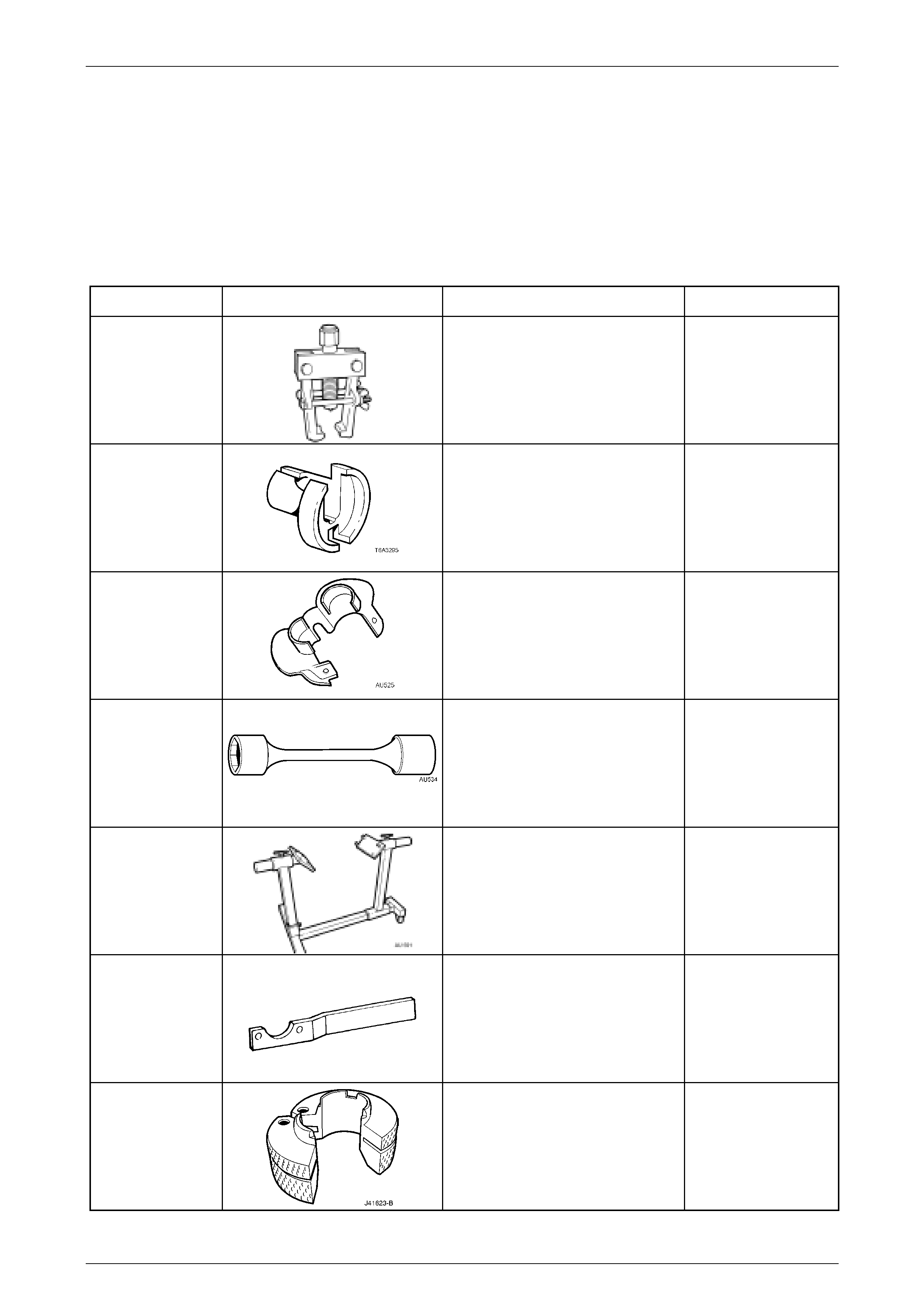
Tool Number Illustration Description Tool Classification
7311 Tie Rod Ball Joint Remover
Used to disconnect the steering tie
rod end from the steering knuckle.
Previously released.
Desirable
7371
Quick Connect Release Tool - 3/8"
Used for releasing the fuel hose quick
connect fitt ing s at the dash panel and
fuel rail, once the fuel system
pressure has been released.
Previousl
y
released.
Mandatory
AU 525
Quick Connect Release Tool
Used to release the automatic
transmissi on coo ler line qui ck conn ect
fittings at the radiator end.
Previously released.
Mandatory
AU 534
Torque Limiting Socket
Used in conjunction with and impact
gun to tighten the wheel nuts.
Previously released.
Mandatory
AU 591 Engine Stand
Used to support the GEN III V8
engine. Allows 360° rotation
capability.
Previously released.
Available
KM-468
Holding Bar
Used to hold the wheel hub while
loosening the front driveshaft retaining
nut.
Previously released.
Unique
J 41623-B Cooler Line Disconnect Tool
Used to disconnect the automatic
transmission fluid cooler lines at the
Quick Connect fittings at the
transmission.
Previousl
y
released.
Mandatory
Engine Mechanical – GEN III V8 Engine Page 6A3-40
Page 6A3–40
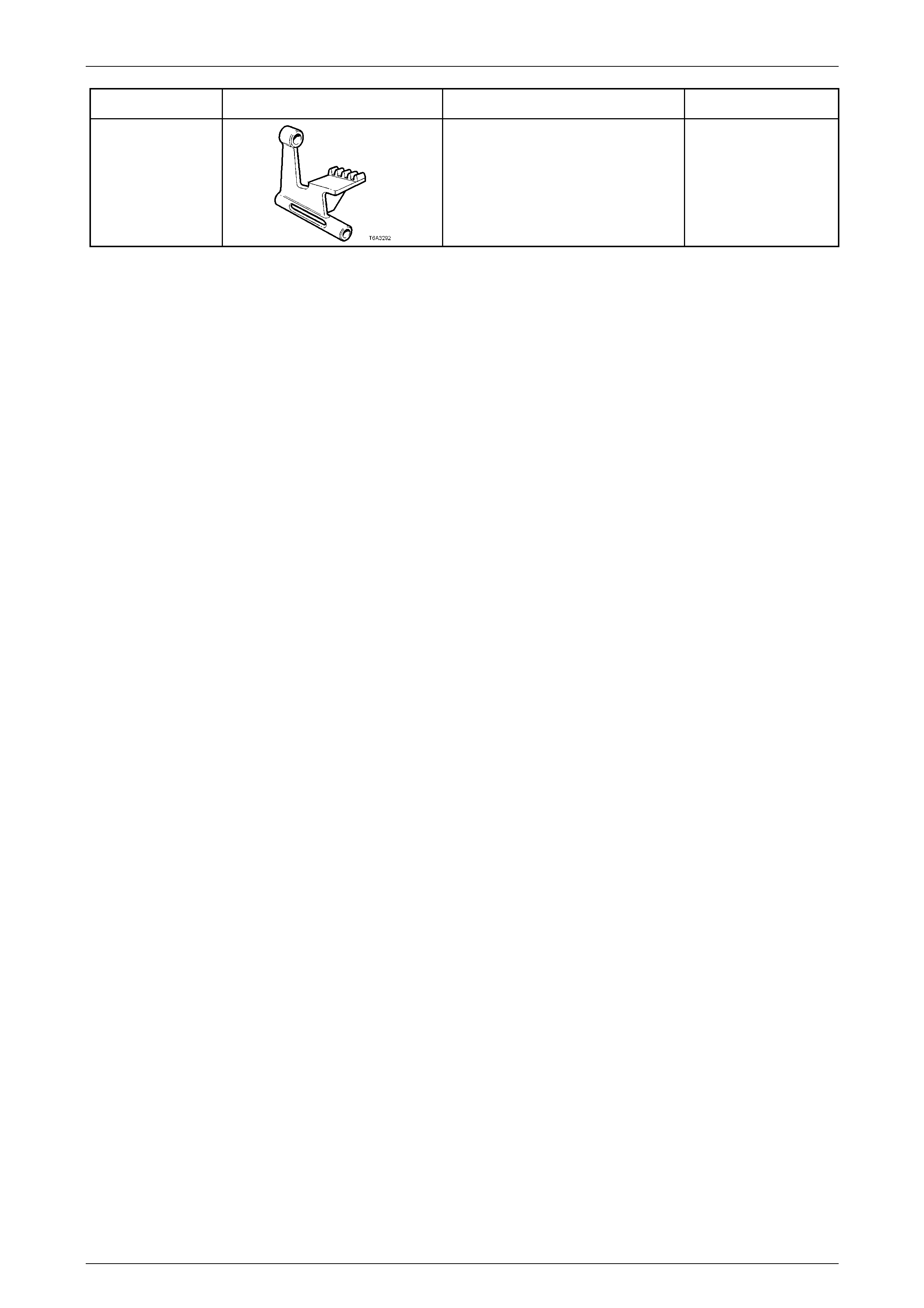
Tool Number Illustration Description Tool Classification
J 42386-A
Engine Ring Gear Holding Tool
Used to hold the GEN III V8 Engine
ring gear.
Previously released.
Desirable