
Powertrain Management – General Information – GEN III V8 Engine Page 6C3-1-1
Page 6C3-1-1
Section 6C3-1
Powertrain Management – General In formation –
GEN III V8 Engine
ATTENTION
Before performing any Service Operation or other procedure described in this Section, refer to Section 00
Warnings, Cautions And Notes for correct workshop practices with regard to safety and/or property damage.
1 General Information............................................................................................................................... 2
1.1 Powertrain Interface Module (PIM)........................................................................................................................2
PIM Diagnostic Trouble Codes..............................................................................................................................3
Diagnostic Trouble Code History Data................................................................................................................3
Tech 2 Read DTC Information............................................................................................................................4
Powertrain Interface Module Circuits and DTCs .................................................................................................4
Starter Relay.......................................................................................................................................................4
ABS, Low Traction, and Brake Fail Warnings.....................................................................................................6
Low Speed Fan, No BCM Response..................................................................................................................7
No Serial Data From PCM..................................................................................................................................7
1.2 Underhood Fuse and Relay Centre.......................................................................................................................9
Techline
Powertrain Management – General Information – GEN III V8 Engine Page 6C3-1-2
Page 6C3-1-2
1 General Information
With the introduction of the MY 2004 AWD Wagon range of vehicles, there are a number of unique powertrain
management features, that are detailed in this Section. For all remaining diagnostic and servicing information, refer to
Section 6C3 Powertrain Management, in the MY 2004 VY and V2 Series Service Information.
The Powertrain Interface Module (PIM) diagnostic capabilities have been modified, that now results in six Diagnostic
Trouble Codes (DTC) that can be stored in memory, with different identification numbering than previously used.
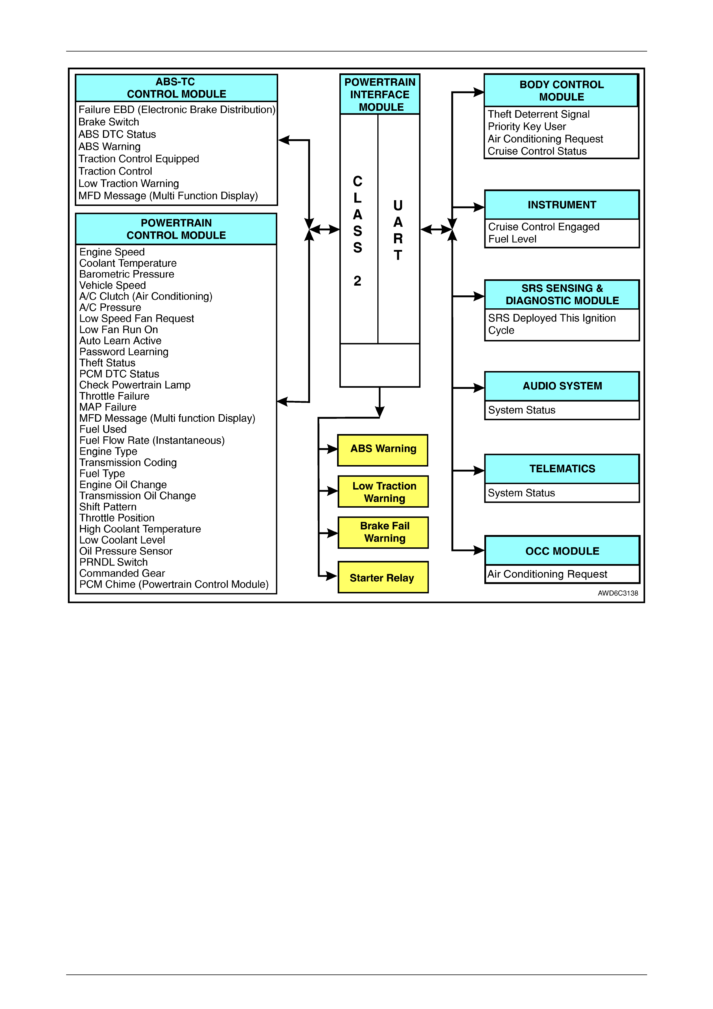
The ABS-TC system fitted to this vehicle, operates on the Class 2 serial data bus, which means that the PIM must now
interact with this ABS-TC control module, in addition to the Powertrain Control Module (PCM). The design of the ABS-TC
system also results in the Throttle Relaxer module and associated components, is \no longer required. Also, in addition
to controlling the operation of the Start Relay (R1). The PIM now activates the following hard wired warnings, to the
Instrument:
• ABS Warning
• Low Traction Warning
• Brake Fail Warning
Refer to Figure 6C3-1-2 for a schematic representation of the revised control arrangements.
By adopting the same engine cooling system control arrangement, as fitted to MY 2003 Regular Cab Chassis, an
additional relay is now fitted to the underhood electrical centre, the operation of which, is detailed in Section 6B3 Engine
Cooling – GEN III V8 Engine, in the MY 2003 Regular Cab Chassis Service Information. Refer to Figure 6C3-1-8 , in this
Section, for all underhood relay, fusible link and fuse locations fitted to MY 2004 AWD Wagon models. For all remaining
diagnostic information relating to the engine cooling fans, refer to Section 6C3-2A Diagnostic Tables, in the MY 2004
AWD Wagon Service Information.
1.1 Powertrain Interface Module (PIM)
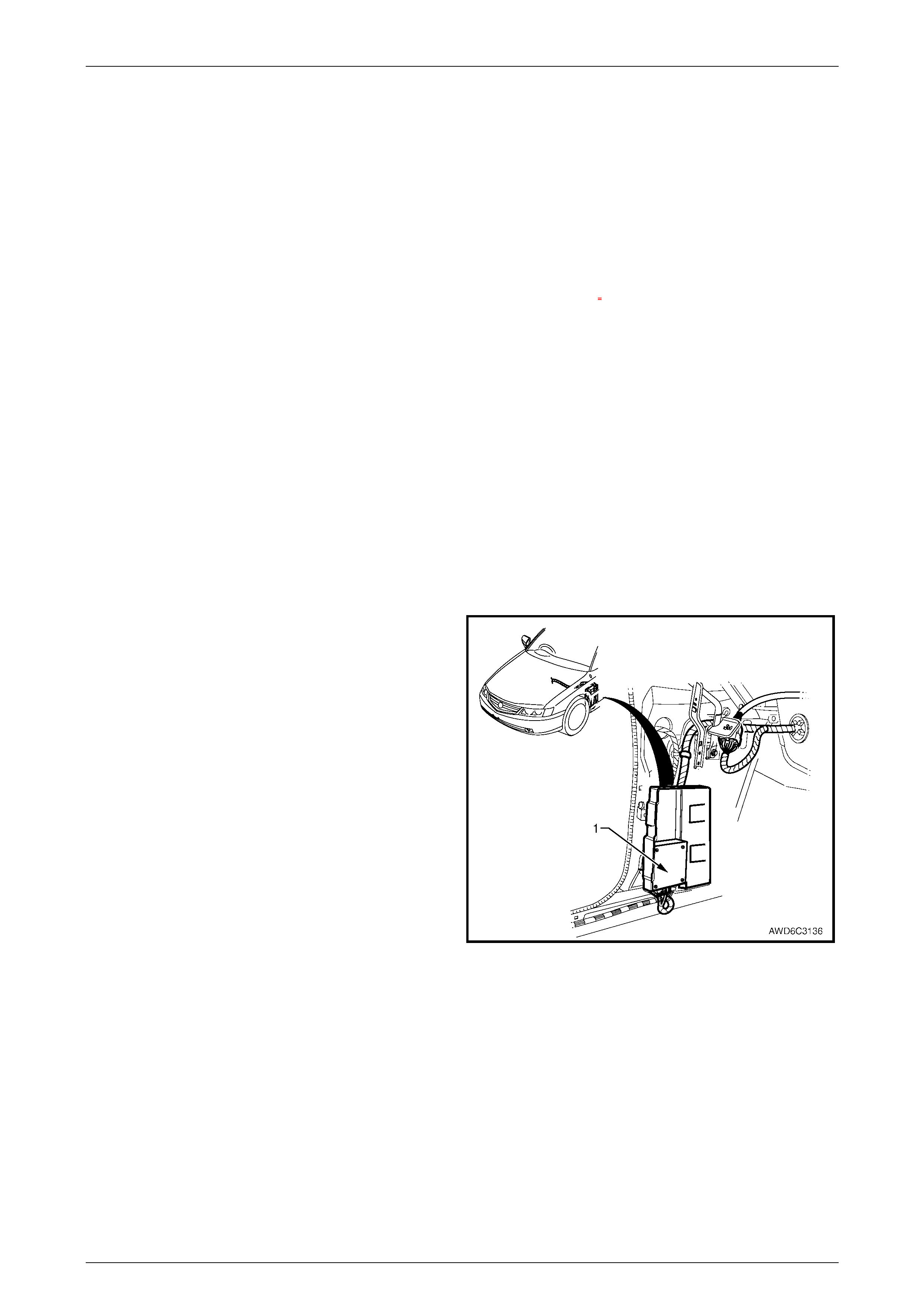
The Powertrain Interface Module (PIM) (1), is located in the
vehicle, behind the left kick panel. The PIM (1) acts as a
communication translator between the PCM and the ABS-
TC modules on the Class 2 Serial Data circuit and other
control modules on the UART serial data circuit to the PCM.
The PCM and ABS-TC control modu les use Class 2 serial
data to communicate, while other control modules in the
vehicle are designed to transmit serial data via UART
protocol. Refer to Serial Data Communication, in
Section 6C3-1 General Information in the MY 2003 VY and
V2 Series Service Information, for more detailed information
on these two serial data types.
Figure 6C3-1-1 – PIM Location
Powertrain Management – General Information – GEN III V8 Engine Page 6C3-1-3
Page 6C3-1-3
Figure 6C3-1-2 – PIM Communication
PIM Diagnosti c Troubl e Codes
A PIM malfunction may affect vehicle operation and may interrupt starter motor operation. For PIM diagnosis refer to
Section 6C3-2A Diagnostic Tables in the MY 2004 AWD Wagon Service Information, PIM DTC diagnosis. There are six
(6) PIM DTCs that may set. Each of these DTCs have corresponding diagnostic tables, also detailed in 6C3-2A
Diagnostic Tables.
Diagnostic Trouble Code History Data
When the Powertrain Interface Module (PIM) detects an operating parameter which is outside its calibrated values, it will
set a Diagnostic Trouble Code (DTC) and store this DTC into its memory as a current DTC. When a current DTC is set
the Check Powertrain MIL may be activated.
When a DTC is set, the PIM also stores the following history data for each DTC.
DTC Status ..........................................Current or History
DTC Number ........................................The DTC number is the number used to identify a particular fault condition.
Occurrence Count (0 to 255)................The occurrence count is the number of times the particular fault condition has
been detected.
History Count (0 to 255) The history count is the number of ignition cycles that have occurred since the
fault was last detected. A count of 0 indicates the fault has occurred on the
current ignition cycle, while a count of 255 indicates that the fault occurred 255 or
more ignition cycles ago.
Powertrain Management – General Information – GEN III V8 Engine Page 6C3-1-4
Page 6C3-1-4
The occurrence and history counters provide a means of determining how often the fault has occurred, and how long it
has been since the fault last occurred. For instance, if the DTC occurrence count is 1, and the history count is 201, then it
can be determined that the fault condition existed only once, and it happened 201 ignition cycles ago (and has not been
detected since). Another example would be an occurrence count of 4 and a history count of 0. This would indicate that
the fault has been detected a total of four times, and that it was detected on the current ignition cycle.
Current and History DTCs and DTC history data can be read and cleared using TECH 2.
Tech 2 Read DTC Information
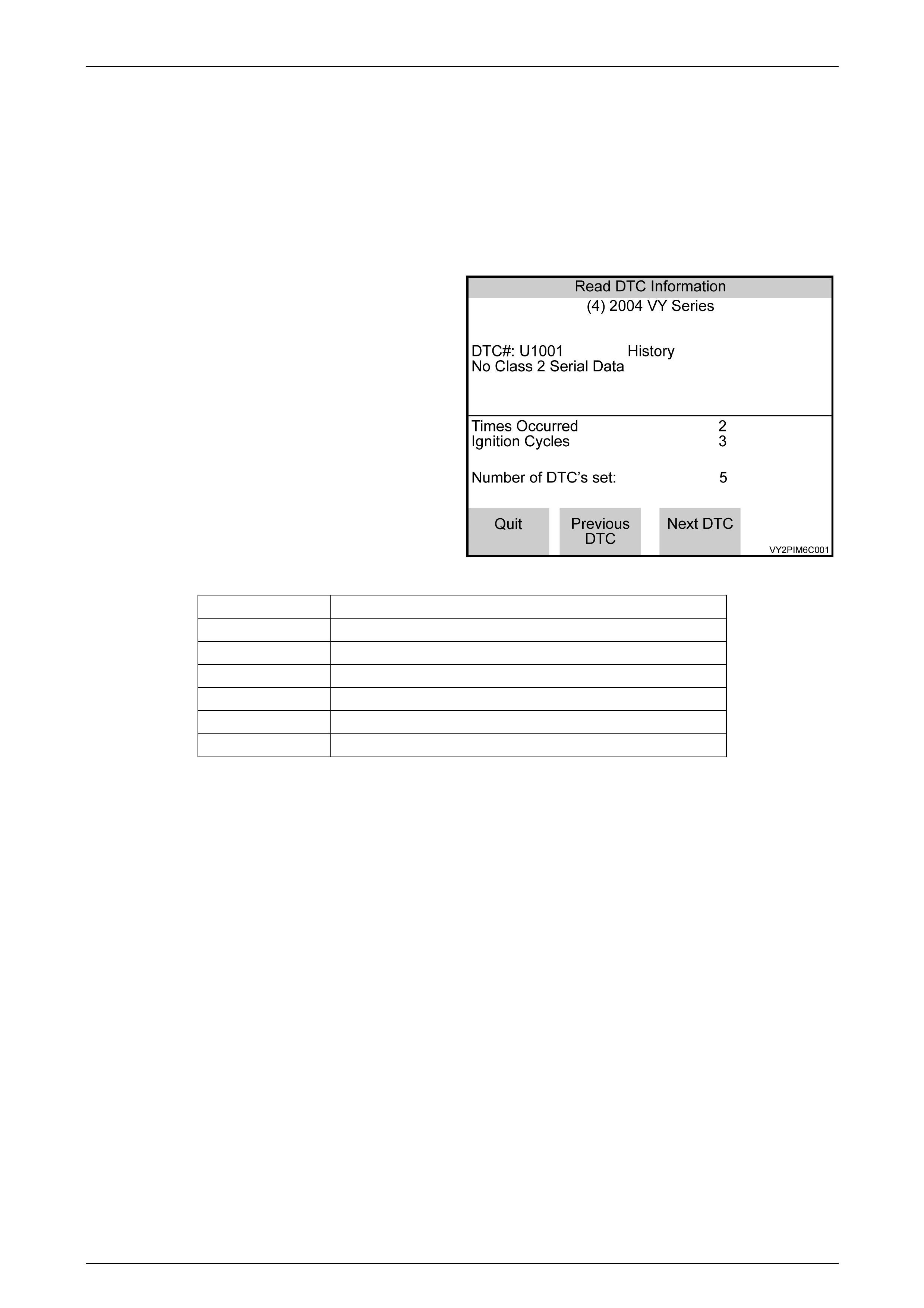
Tech 2 will display the DTC information in the following manner:
F0: Read DTC Information
When this mode is selected, TECH 2 will display the
following DTC information:
• The DTC Number
• DTC Status either Current or History
• DTC Description
• Times Occurred
• Ignition Cycles since the DTC last set
• Number of DTCs set
Figure 6C3-1-3 – PIM Read DTC Information
DTC DTC Description
U1000 No Class 2 Serial Data
U1001 No Serial Data From PCM
U1043 No Serial Data From ABS - TC
U1064 No Serial Data From BCM
B1009 EEPROM Checksum Error
B3027 Starter Enable Circuit Range / Performance
Table 1 – PIM Diagnostic Trouble Codes
Powertrain Interface Module Circuits and DTCs
Starter Relay
The PIM controls the operation of the starter relay. When the ignition switch is turned to the ON position, the PIM will
enable the starter relay for one second. If the PIM does not receive the correct theft deterrent signal from the BCM, it will
disable the starter relay. If the PIM receives the correct signal from the BCM, it will continue to enable the start relay.
When the engine has started and the engine speed is above 500 RPM, the PIM will disable the starter relay, preventing
starter engagement while the engine is running.
If the serial data bus between the BCM and the PIM should fail (no polling from the BCM for more than 60 seconds after
successful theft deterrent communications, the PIM will allow subsequent starts, however there will be a crank delay of
one second. If the PIM receives valid communication, normal operation will resume.
If the Class 2 serial data bus between the PIM and the PCM should fail (no communications for 20 seconds) after
successful theft deterrent communications, the PCM will allow subsequent starts, however there will be a crank delay of
one second. If communications between the PCM and the PIM are re-established, norm al operation will resume.
When the ignition key is turned to the crank positi on, power is supplied to the starter relay terminal X1 85. After receiving
the proper theft deterrent signal from the BCM, the PIM will supply a ground signal to the starter relay, terminal X1 86.
This will energise the starter relay and allow the starter motor to operate.
If there is a problem with the starter relay coil (shorted internally) or the starter relay control circuit (s horted to voltage),
that is allowing 12 volts on the starter relay control circuit, this will cause the PIM to set DTC B3027 Starter Enable Circuit
Range/Performance.

Powertrain Management – General Information – GEN III V8 Engine Page 6C3-1-5
Page 6C3-1-5
Figure 6C3-1-4 – Starter Circuit
Powertrain Management – General Information – GEN III V8 Engine Page 6C3-1-6
Page 6C3-1-6
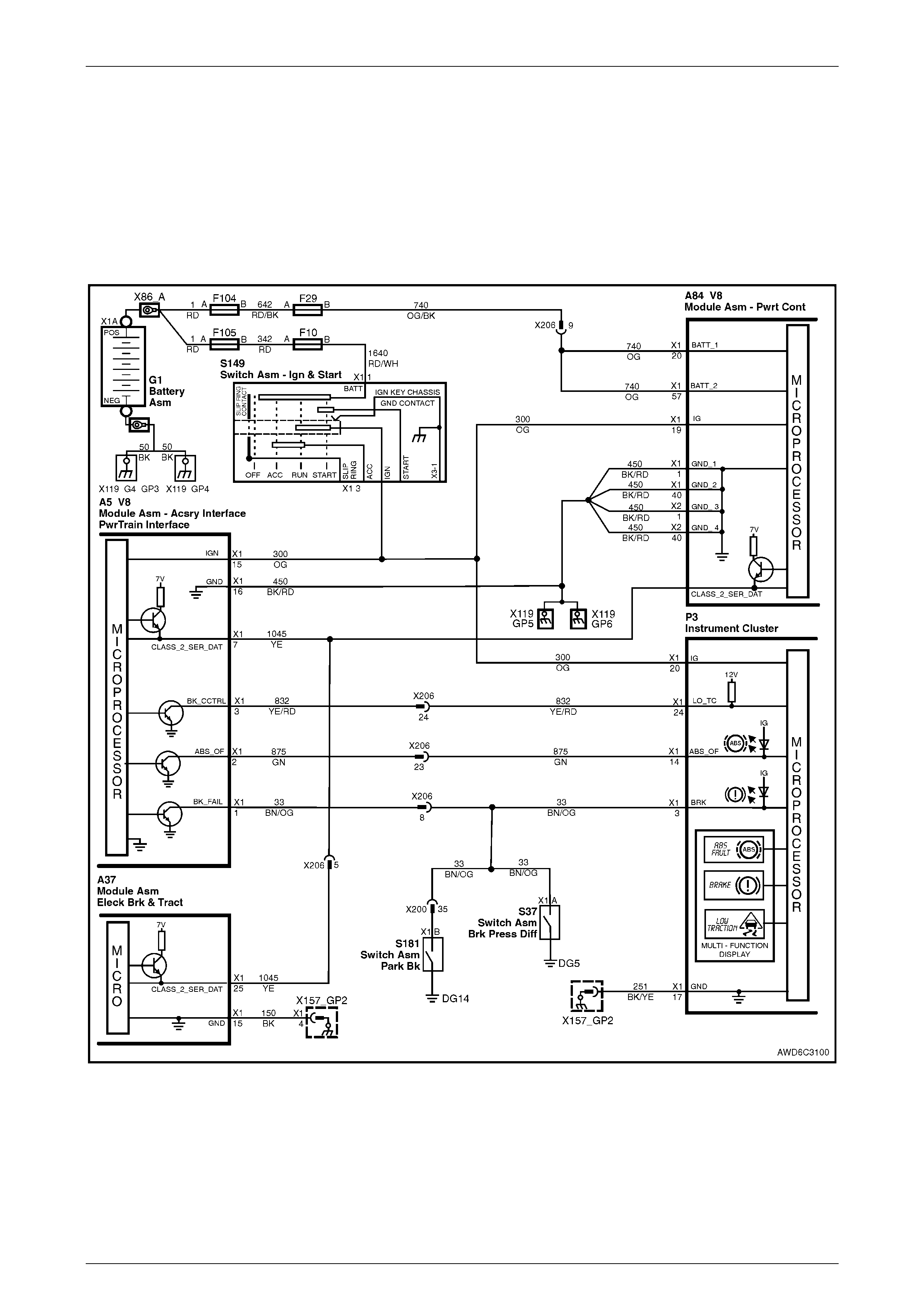
A BS, Low Traction, and Brake Fail Warnings
Acting on information received from the ABS – TC Module, the PIM is able to activate the ABS, Low Traction, or Brake
Fail Warning/s. To activate any of these warmings, the ABS – TC module will send a Class 2 serial data message to the
PIM requesting that the warning be activated. On receiving a request to activate any of these warnings, the PIM will
ground the appropriate warning circuit from the instrument.
The Brake Fail Warning can also be activated when the brake pressure differential switch is closed or the park brake is
applied.
If the PIM does not receive Class 2 serial data from the ABS – TC Module, DTC U1043, 'No Serial Data From ABS – TC'
will be set and the PIM will activate the ABS and Brake Fail Warnings.
Figure 6C3-1-5 – Warning Circuits
Powertrain Management – General Information – GEN III V8 Engine Page 6C3-1-7
Page 6C3-1-7
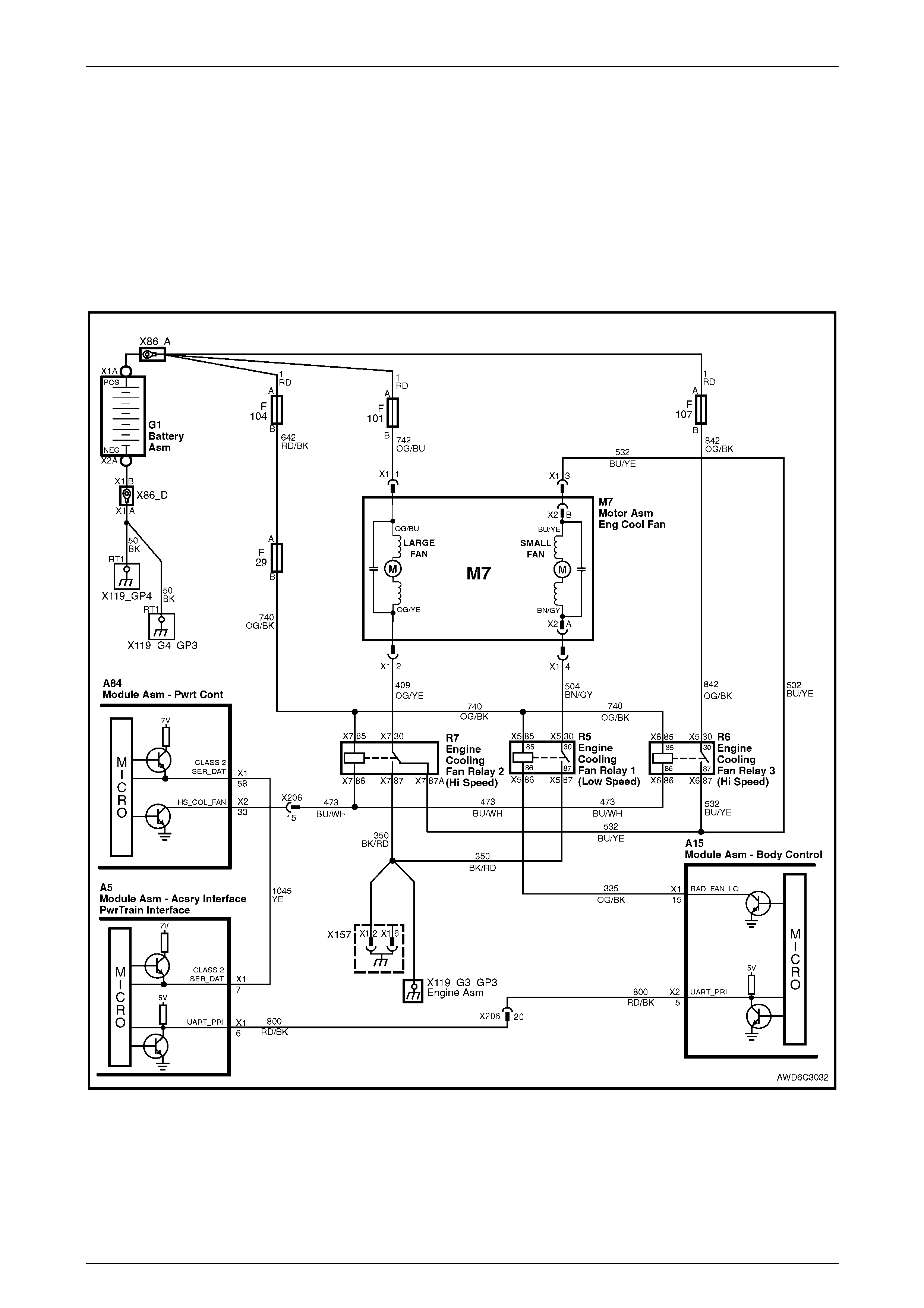
Low Speed Fan, No BCM Response
The PCM determines operation of the two speed engine cooling fans based on A/C request, engine coolant temperature,
A/C pressure sensor, and vehicle speed.
The engine cooling fan Low Speed Relay (R5) is energised by the BCM. When the PCM determines that the low speed
fan relay should be enabled, the PCM will send a message on the Class 2 serial data circuit to the PIM. The PIM will then
convert the PCM Class 2 message to a UART message and supply this UART message to the BCM. This PCM message
will request the BCM to supply the needed ground signal for the Low Speed Relay (R5) to operate. After the BCM
provides the ground signal for the Low Speed Relay, the BCM will send a message back to the PIM confirming that the
ground signal was commanded. The PIM will convert this message from the BCM to Class 2 and supply it to the PCM.
If the PIM sends a Low Speed request signal to the BCM and does not receive a response back from the BCM, DTC
U1064 – No Serial Data from BCM will be set.
Figure 6C3-1-6 – Cooling Fan Circuit
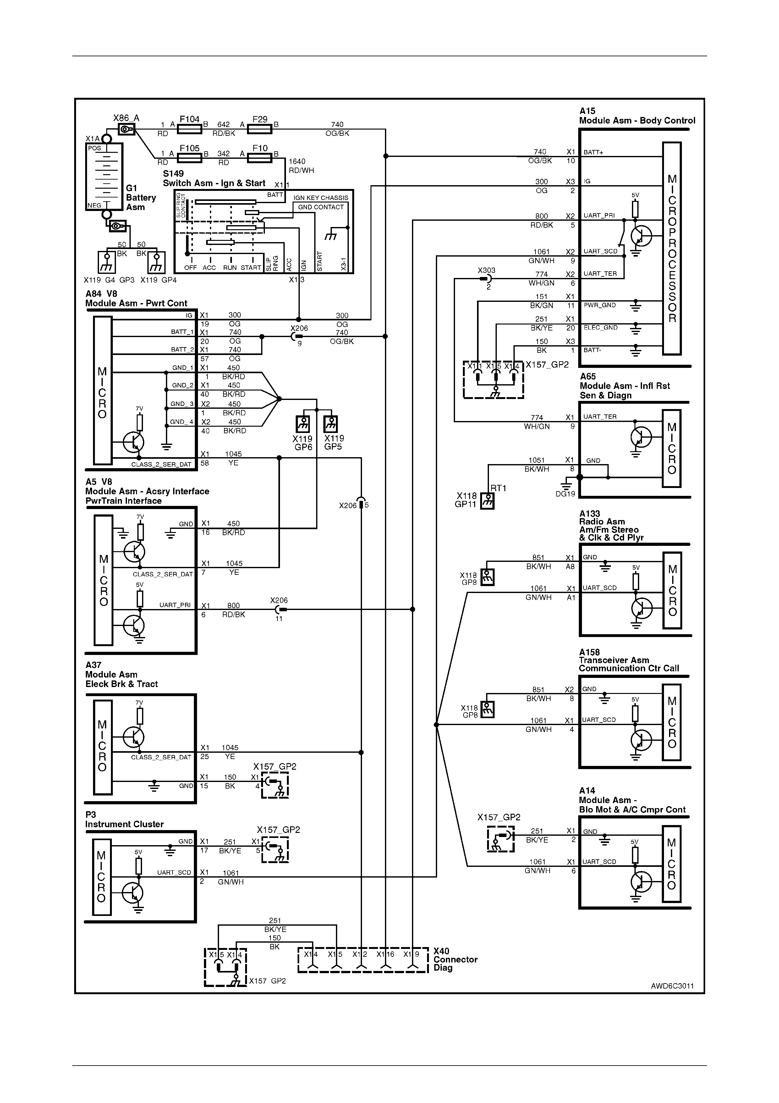
No Serial Data From PCM
The PIM receives information from the PCM on the Class 2 serial data circuit. If there is a problem with this circuit or the
PCM is not communicating, the PIM will detect this lack of information and will set a DTC. Also, if there is a problem with
the serial data circuit, performing the Powertrain OBD System Check will lead you to the Data Link Connector Diagnosis,
where the problem that set this DTC will be diagnosed.
Powertrain Management – General Information – GEN III V8 Engine Page 6C3-1-8
Page 6C3-1-8
If the PIM does not receive any serial data communication from the PCM, DTC U1001 No Serial Data from PCM, will set.
Figure 6C3-1-7 – Serial Data Circuits
Powertrain Management – General Information – GEN III V8 Engine Page 6C3-1-9
Page 6C3-1-9
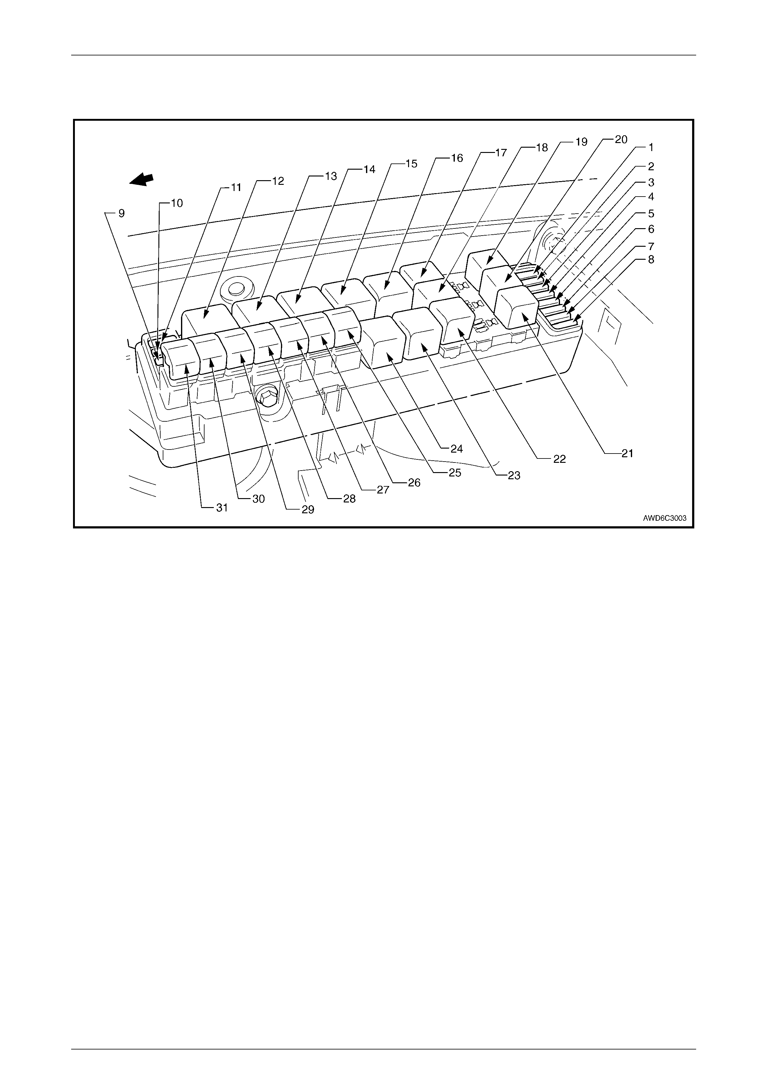
1.2 Underhood Fuse and Relay Centre
Figure 6C2-2A-8 – Engine Compartment Fuse/Relay/Fusible Link Locations
Legend
Fuses
1 Fuel Pump Fuse – F28
2 Engine Control, B CM & Telematics – F29
3 RH Headlamp – F30
4 LH Headlamp – F31
5 Automatic Transmission – F32
6 Engine Sensors – F33
7 Fuel Injectors / Ignition Modules – F34
8 Fuel Injectors / Ignition Modules – F35
9 Antilock Brakes – F36
10 Power Outlet – F37
11 Level Ride – F38
Relays
12 Start – R1
13 Blower Fan – R2
14 Headlamp (High Beam ) – R3
15 Engine Control (EFI) – R4
16 Engine Cooling Fan Relay 1 (Low Speed) – R5
17 Horn – R8
18 A/C Compressor – R11
19 Fog Lamp – R10
20 Level Ride – R13
21 Fuel Pump – R16
22 Headlamp (Low Beam) – R14
23 Engine Cooling Fan Relay 2 (High Speed) – R7
24 Engine Cooling Fan Relay 3 (High Speed) – R6
Fusible Links
25 Engine Cooling Fan Small – F107 (30A)
26 Blower Fan – F106 (40A)
27 Main – F105 (60A)
28 Engine – F104 (60A)
29 ABS – F103 (60A)
30 Lighting – F102 (60A)
31 Engine Cooling Fan Large – F101 (30A)