
Powertrain Management – Diagnosis – GEN III V8 Engine Page 6C3-2-1
Page 6C3-2-1
Section 6C3-2
Powertrain Management – Diagnosis –
GEN III V8 Engine
ATTENTION
Before performing any Service Operation or other procedure described in this Section, refer to Section 00
Warnings, Cautions And Notes for correct workshop practices with regard to safety and/or property damage.
1 General Information............................................................................................................................... 2
2 TECH 2 Display Modes.......................................................................................................................... 3
F0: Normal Mode...........................................................................................................................................................3
F0: PCM Normal Mode...........................................................................................................................................3
Test Description..................................................................................................................................................3
F0: PCM Normal Mode Descriptions ..................................................................................................................4
F1: ABS-TC Normal Mode......................................................................................................................................7
F1: ABS-TC Normal Mode Descriptions.............................................................................................................7
F1: Diagnostic Trouble Codes.....................................................................................................................................8
F0: Read DTC Information.....................................................................................................................................8
Diagnostic Trouble Code History Data................................................................................................................8
F1: Clear DTC Information.....................................................................................................................................8
F2: Data List..................................................................................................................................................................9
F0: Data List............................................................................................................................................................9
F0: Data List Display Descriptions......................................................................................................................9
F1: System Identification ..................................................................................................................................11
F3: Snapshot...............................................................................................................................................................12
F4: Miscellan eous Test s ............................................................................................................ ................................13
F0: Output Tests...................................................................................................................................................13
F0: Starter Relay:..............................................................................................................................................13
F1: Low Traction Warning:................................................................................................................................13
F2: ABS Warning: .............................................................................................................................................13
F3: Brake Fail Warning:.....................................................................................................................................13
F5: Security.................................................................................................................................................................14

Powertrain Management – Diagnosis – GEN III V8 Engine Page 6C3-2-2
Page 6C3-2-2
1 General Information
With the introduction of the new Anti-Lock Braking and Traction Control (ABS-TC) system, fitted to MY 2004 AWD
Wagon models and the fact that this system communicates via the Class 2 serial data bus, the Powertrain Interface
Module (PIM) has undergone a number of changes. This has also meant that the Diagnostic Trouble Codes (DTCs) have
also been revised and updated, with a changed numbering structure.
Now the PIM acts as a communication translator between the Powertrain Control Module (PCM) and the ABS-TC control
module on the Class 2 serial data bus and other control modules on the UART serial data circuit. In addition to control of
the starter relay operation, the PIM also now controls the operation of warnings triggered by the ABS-TC control module.
These changes have meant that the PCM Normal Mode and Data Display have been updated. For further general
information regarding these changes, refer to Section 6C 3-1 General I nfor mat ion, in the MY 2004 AWD Wagon Service
Information.
In conjunction with these changes, the TECH 2 scan tool software has also undergone an updating process.
All of these changes and the effect they have on TECH 2 displays, are covered in this Section. For all remaining TECH 2
diagnostic information, refer to Section 6C3-2 Diagnosis, in the MY 2003 VY and V2 Series Service Information.

Powertrain Management – Diagnosis – GEN III V8 Engine Page 6C3-2-3
Page 6C3-2-3
2 TECH 2 Display Modes
Access to the TECH 2 display modes for the Powertrain Interface Module (PIM), is via F3: Body from the Main Menu,
then F1: Powertrain Interface Module.
Selections then, are:
F0: Normal Mode
F1: Diagnostic Trouble Codes
F2: Data Display
F3: Snapshot
F4: Miscellaneous Tests
F5: Security
F0: Normal Mode
F0: PCM Normal Mode
In this test mode, TECH 2 will display various engine and transmission data parameters that are being continually
transmitted to other control modules via the serial data circuit normal mode message. The information in the following
tables may b e used for comparison, if a status report is being sent from t he PIM.
1. After completing the Powertrain OBD System Check
2. Finding the on-board diagnostics are functioning properly and;
3. No diagnostic DTCs are displayed.
Test Description
NOTE
The number(s) below refer to the step number(s)
on the diagnostic table.
1 TECH 2 – F0: PCM/PIM Normal Mode will display scan positions that will be displayed in order. TECH 2 will
display nine (9) scan position parameters at a time. The down arrow button will scroll down through all of the scan
positions one at a time. After TIME FROM START parameter is displayed, pressing the down arrow button again
will display scan position parameters starting at the top of the list again.
2 Units Displayed are the available ways of displaying what each parameter is currently operating in, or a value that
is being sensed or being issued by the PCM.
3 Typical Data Value is separated into two parts. These displayed values are typical of a normally operating vehicle.
The Ignition On comparison should be performed first as this may lead to a quick identification of a failure. The
Engine Running data should be compared to the IGNITION ON data as a diagnostic check to make sure the
component or system is operating properly.
4 Ignition On values are the typical values that should be seen on TECH 2 with the ignition ON and engine stopped.
Temperature sensors should be compared to the actual temperatures by allowing the sensor to cool overnight and
then comparing their values. A difference of 3-5° C from the actual temperature may indicate a problem with the
sensor. Use the diagnostic aids table for that sensor to compare the resistance to temperature values.
5 Engine Running typical data values are an average of display values recorded from normally operating vehicles at
normally operating temperature. They are intended to represent what a normally functioning system would typically
display.

Powertrain Management – Diagnosis – GEN III V8 Engine Page 6C3-2-4
Page 6C3-2-4
TECH 2 Scan Tool – F0: PCM Normal Mode
Typical Data Value !
Scan Position " Units Displayed # Ignition On $ Engine Running %
Engine Speed rpm 0 rpm 600 - 650 rpm
(± 50 rpm in Drive)
Coolant Temperature Degrees C Varies +96° C
Barometric Pressure kPa 0 to 200 kPa
(Varies) 0 to 200 kPa
(Varies)
Vehicle Speed km/h 0 km/h 0 km/h
A/C Clutch On /Off Off Off
A/C Pressure kPa 300 – 1200 kPa 300 – 1200 kPa A/C Off
500 – 1900 kPa A/C On
Low Speed Fan Request On / Off Off Off
Low Fan Run On Yes / No No No
Auto Learn Active Yes / No No No
Password Learning Yes / No No No
Theft Status (only BCM-PIM) No Start / Start Start Start
PCM DTC Status No DTC/DTC(s) Set No DTC No DTC
Check Powertrain MIL Off/On Off Off
Throttle Failure Yes/No No No
MAP Failure Yes/No No No
MFD Mes sa ge
(Multi Function Display) Yes/No No No
Fuel Used L 00.00 1 – 2 L
Fuel Flow Rate
(Instantaneous) L/Hour 00.00 1 – 4 L/Hour
Engine Type V6,
V6 Supercharged
V8 GEN III V8 GEN III V8 GEN III
Transmission Coding Manual Trans.
Automatic Trans. Manual Trans.
Automatic Trans. Manual Trans.
Automatic Trans.
Fuel Type Petrol / LPG Petrol Petrol
Engine Oil Change Okay / Service
Requested Okay Okay
Transmission Oil Change Okay / Service
Requested Okay Okay
Shift Pattern Power / Economy Economy Economy
Throttle Position 0-100 % 0% 0%
High Coolant Temperature Yes/No No No
Low Coolant Level Yes/No No No
Oil Pressure Switch Off/On Off Off
PRNDL Switch Invalid /
P,R,N,D,3,2,1 –P– –P–
Commanded Gear P/N R, 1,2,3,4 –P/N– –P/N–
PCM Chime Yes/No No No
F0: PCM Normal Mode Descriptions
A list of explanations for each data message displayed on TECH 2 is listed below. This information will assist in
diagnosing emission or driveability problems. The displays can be viewed while the vehicle is being driven. Refer to the
Powertrain OBD System Check for additional information.
Engine Speed: TECH 2 Displays a range of 0 to 9999 RPM
The engine speed is computed by the PCM from the fuel control reference input. It should remain close to desired idle
speed under various engine loads with engine idling.

Powertrain Management – Diagnosis – GEN III V8 Engine Page 6C3-2-5
Page 6C3-2-5
Coolant Temperature: TECH 2 Displays a range of -39°C to 140°C
The Engine Coolant Temperature (ECT) Sensor is mounted in the cylinder head of the left bank. The PCM applies 5.0
volts to the ECT sensor circuit. The sensor is a thermistor which changes internal resistance as temperature changes.
When the sensor is cold (internal resistance high), the PCM monitors a high signal voltage and interprets the voltage as
a cold engine. As the sensor warms (internal resistance decreases), the voltage signal decreases and the PCM
interprets the lower voltage as a warm engine.
Barometric Pressure: TECH 2 Displays a range of 0 to 200 kPa
The BARO reading is displayed in kPa and represents the altitude of the vehicle for the transmission control. At sea level
the BARO reading is about 101 kPa. At 3,048 meters the BARO reading is about 96 kPa.
Vehicle Speed: TECH 2 Displays a range of 0 to 255 km/h
The vehicle speed sensor signal is converted into km/h for display.
A/C Clutch: TECH 2 Displays "ON" or "OFF"
Represents the commanded state of the A/C clutch control relay. Clutch should be engaged when ON is displayed.
A/C Pressure: TECH 2 Displays a range of 0 to 3195 kPa
The kPa displayed indicates that the PCM is monitoring an A/C Refrigerant Pressure signal voltage which is too high or
too low to allow the A/C compressor clutch to engage.
Low Speed Fan Request: TECH 2 Displays "ON" or "OFF
Indicates if the engine cooling fan low speed relay has been commanded ON or OFF.
Low Fan Run On: TECH 2 Displays "NO" o r "YES"
This indicates if the PCM is requesting the BCM to turn the Low Speed Fan ON at key OFF.
Auto Learn Active: TECH 2 Displays "NO" or "YES"
This indicates if the PCM Auto Learn Mode is Active when TECH 2 displays YES.
Password Learning: TECH 2 Displays "NO" or "YES"
This indicates if the PCM is learning the PIM password.
Theft Status: TECH 2 Displa ys "NO STAR T" or "START"
Indicates the status of the Theft Deterrent System.
PCM DTC Status: TECH 2 Displ ays "NO DTC" or “DTC SET”
Indicates if a DTC is set. This does not indicate what DTC is set, just informs that DTC(s) are or are not set.
Malfunction Indicator Lamp (MIL): TECH 2 Displays "OFF" or "ON"
Indicated if the instrument panel Malfunction Indicator Lamp (MIL) is activated or not.
Throttle Failure: TECH 2 Displays "NO" or "YES"
Indicates if the throttle position sensor has failed. This is reported from the PCM to the PIM.
MAP Failure: TECH 2 Displays "NO" or "YES"
Indicates if the Map sensor has failed. This is reported from the PCM to the PIM.
MFD Message: TECH 2 Displays "NO" o r "YES"
Indicates if PCM is sending an additional MFD message to the instruments.
Fuel Used: TECH 2 Displays a range of 0 to 1000 Litres
When the key is turned ON and the engine is running, the PCM will calculate FUEL USED during each ignition cycle.
Fuel Flow Rate: TECH 2 Displays a range of 0 to 100 litres
Indicates fuel consumption per litres per hour.
Engine Type: TECH 2 Displays Engine Type
The TECH 2 uses this information for proper TECH 2 scan tool software.

Powertrain Management – Diagnosis – GEN III V8 Engine Page 6C3-2-6
Page 6C3-2-6
Transmission Coding: TECH 2 Displays “MANUAL” or “AUTOMATIC”
The TECH 2 uses this information for proper TECH 2 scan tool software.
Fuel Type: TECH 2 Displ ays “PETROL” or “LPG”
The scan tool will display what fuel type the PCM software is set up for.
Engine Oil Change: The TECH 2 Displays “OKAY” or “SERVICE REQUESTED”
The scan tool will display the status of the engine oil change condition.
Transmission Oil Change: The TECH 2 Displays “OKAY” or “SERVICE REQUESTED”
The scan tool will display the status of the transmission oil change condition.
Shift Pattern: TECH 2 Displays “ECONOMY” or “POWER”
This display shows the state of the POWER/ECONOMY switch.
Throttle Position: TECH 2 Displays a range of 0 to 100%
Computed by the PCM from TP sensor voltage (Throttle Position) should read 0% at idle and 100% at Wide Open
Throttle (WOT).
High Coolant Temperature: TECH 2 Displays "NO" o r "YES"
This is an indicat ion from the PCM that the engine is runnin g hot.
Low Coolant Level: TECH 2 Displays "NO" or "YES"
This is an indication from the PCM that the coolant level is low, and the Instrument will activate the Low Coolant warning
icon in the MFD.
Oil Pressure Sensor: TECH 2 Displays "OFF" or "ON"
This is an indication to the PCM if the oil pressure is high or low. If the oil pressure is low, the Instrument will activate the
Low Oil Warning icon in the MFD.
PRNDL Switch: TECH 2 Displays “INVALID” or “P, R, N, D, 3, 2, 1”
This displays if the ve hic le is not equipped with a PRNDL switch (INVALID), or if equipped, indicates what gear the driver
has select ed.
Commanded Gear: TECH 2 Displays “1, 2, 3, 4”
The gear that the PCM is commanding the transmission to be in. In PARK, TECH 2 will display "1", the commanded state
of the shift.
PCM Chime: TECH 2 Displays "NO" or "YES"
This is a indication to the instrument panel allowing the instrument panel to chime if a problem or fault is detected.
Powertrain Management – Diagnosis – GEN III V8 Engine Page 6C3-2-7
Page 6C3-2-7
F1: ABS-TC Normal Mode
In this test mode, TECH 2 will display various ABS data param eters that are being continually transmitted to other control
modules via the serial data circuit normal mode message.
TECH 2 Scan Tool: F1: ABS – TC Normal Mode
Typical Data Value !
Scan Position " Units Displayed # Ignition On $ Engine Running %
Failure EBD
(Electronic Brake Distribution) No / Yes No No
Brake Switch Inactive/Active Inactive Inactive
ABS DTC Status No DTC/DTCS Set No DTC No DTC
ABS Warning Off / On Off Off
Traction Control Equipped No / Yes Yes Yes
Traction Control Off / On On On
Low Traction Warning Off / On Off Off
MFD Mes sa ge
(Multi Function Display) No / Yes No No
F1: ABS-TC Normal Mode Descriptions
A list of explanations for each data message displayed on TECH 2 is listed below. This information will assist in
diagnosing ABS – TC system problems. The displays can be viewed while the vehicle is being driven.
Failure EBD (Electronic Brake Distribution): TECH 2 Displays "NO" or "YES"
Indicates if the EBD has failed. This is reported from the ABS – TC Module to the to the PIM.
Brake Switch: TECH 2 Displays "INACTIVE" or " ACTIVE"
Display the current status of the Brake Switch.
ABS DTC Status: TECH 2 Displays "NO DTC" or "DTC SET"
Indicates if a DTC is set. This does not indicate what DTC is set, just informs that DTC(s) are or are not set.
ABS Warning: TECH 2 Disp lays "NO" or " YES"
Displays the commanded status of the ABS Warning NO/YES..
Traction Control Equipped: TECH 2 Displays "NO" or "YES"
On all AWD vehicles this should display YES.
Traction Control: TECH 2 Displays "OFF" or "ON"
Displays the current status of the traction control system.
Low Traction Warning: TECH 2 Displays "OFF" or "ON"
Displays the commanded status of the low traction warning.
MFD Message (Multi Function Display) : TECH 2 Displays "NO" or "YES"
Indicates if ABS - TC module is sending an additional MFD message to the instruments.
Powertrain Management – Diagnosis – GEN III V8 Engine Page 6C3-2-8
Page 6C3-2-8
F1: Diagnostic Trouble Codes
In this test mode, PIM DTCs can be displayed or cleared. When F1: Diagnostic Trouble Codes is selected there are an
additional two modes:
F0: Read DTC Information
A listing of all (if any) DTC’s that have been set by the PIM will be displayed. TECH 2 will also display Diagnostic Trouble
Code History Da ta.
Diagnostic Trouble Code History Data
When the PIM detects an operating parameter which is outside its calibrated values, it will set a Diagnostic Trouble Code
(DTC) and store this DTC into its memory as a current DTC. When a current DTC is set the Check Powertrain MIL may
be activated.
When a DTC is set, the PIM also stores the following history data for each DTC:
DTC Number ............................The DTC number is the number used to identify a particular fault condition.
DTC Status ..............................Current or History
Occurrence Count (0 to 255)....The occurrence count is the number of times the particular fault condition has been
detected.
History Count (0 to 255)............The history count is the number of ignition cycles that have occurred since the fault was
last detected. A count of 0 indicates the fault has occurred on the current ignition cycle,
while a count of 255 indicates that the fault occurred 255 or more ignition cycles ago.
The occurrence and history counters provide a means of determining how often the fault has oc curred, and how long it
has been since the fault last occurred. For instance, if the DTC occurrence count is 1, and the history count is 201, then it
can be determined that the fault condition existed only once, and it happened 201 ignition cycles ago (and has not been
detected since). Another example would be an occurrence count of 4 and a history count of 0. This would indicate that
the fault has been detected a total of four times, and that it was detected on the current ignition cycle.
Current and History DTCs and DTC history data can be read and cleared using TECH 2.
TECH 2 will display the DTC information in the following manner:
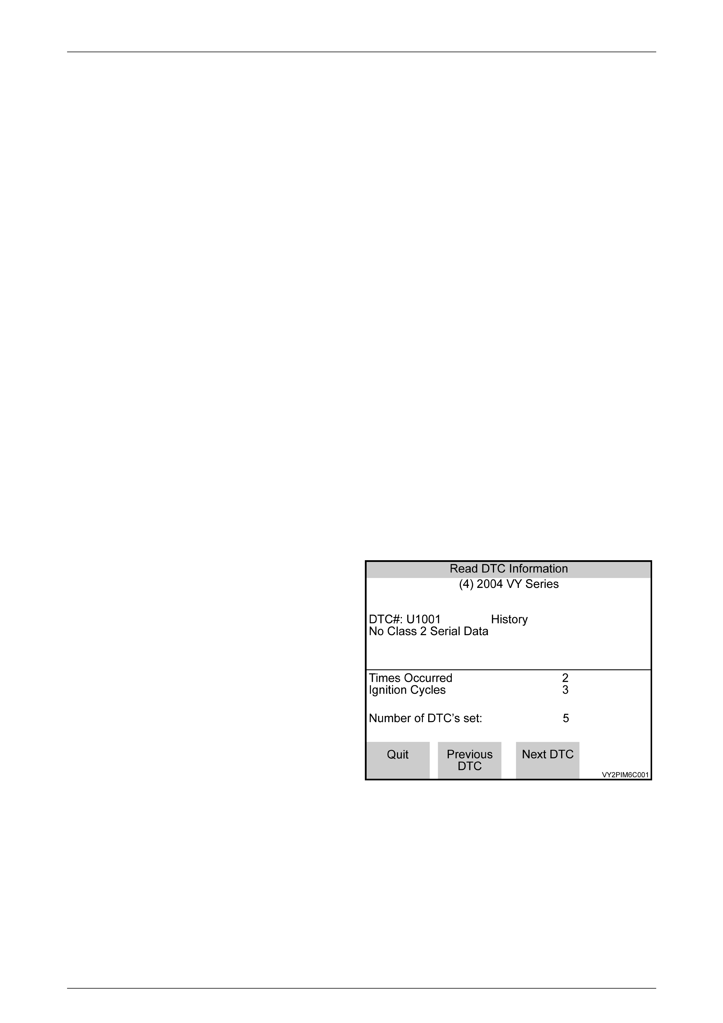
F0: Read DTC Information
When this mode is selected, TECH 2 will display the
following DTC information:
• The DTC Number
• DTC Status either Current or History
• DTC Description
• Times Occurred
• Ignition Cycles since the DTC last set
• Number of DTCs set
Figure 6C3-2 -1 – PIM Read DTC Information
F1: Clear DTC Information
In this Test Mode all DTC in stored in the PIM. Once the DTCs have been cleared the PIM will not store any DTC until
the ignition has been cycled.
Powertrain Management – Diagnosis – GEN III V8 Engine Page 6C3-2-9
Page 6C3-2-9
F2: Data List
In this test mode there are two data lists available F0: Datal List and F1: System Identification.
F0: Data List
TECH 2 Scan Tool: PIM – F2: Data List
TYPICAL DATA VALUE !
SCAN POSITION " UNITS DISPLAYED
# IGNITION ON $ ENGINE RUNNING %
Starter Relay Off/On On Off
Fuel Continue Off/On Yes Yes
Fuel Disable Time-Out Off/On Off Off
Fuel Disable Cycle Ign Off/On Off Off
Auto Learn Active Yes/No No No
PIM Theft Deterrent Communication Lost Yes/No No No
Password Learning Yes/No No No
PIM DTC Status No DTC / DTCs Set No DTC No DTC
A/C Clutch Off/On Off Off
Check Powertrain La mp Off/On Off Off
Low Coolant Level Yes/No No No
Oil Pressure Switch Off/ON Off Off
Engine Oil Change Okay /
Service Reques ted Okay Okay
Engine Oil Life Reset YES/No No No
Shift Pattern Economy / Power Economy Economy
Brake Fail Warning Requested No/YES No No
Brake Fail Warning Off/On Off Off
ABS Warning Requested No/YES No No
ABS Warning Off/On Off Off
Low Traction Warning Requested No/YES No No
Low Traction Warning Off/On Off Off
Traction Control Off Requested No/Yes No No
Traction Control On/Off On On
Brake Switch Inactive / Active Inactive Inactive
EBD (Electronic Brake Distribution) Inactive / Active Inactive Inactive
Low Speed Fan Request Off/On Off Off
Low Speed Fan Run On Yes/No No No
F0: Data List Display Descriptions
A list of explanations for each data message displayed on TECH 2 begins as follows. This information will assist in
tracking emission or driveability problems, since the displays can be viewed while the vehicle is being driven. Refer to
Powertrain OBD System Check for additional information.
Starter Relay: TECH 2 Displays "OFF" or "ON"
The scan tool displays ON when the Start Relay is enabled.
Fuel Continue: TECH 2 Displays "OFF" or "ON"
TECH 2 displays ON if the proper Theft Deterrent signal is sent from the PIM to the PCM for fuel control.
Fuel Disable Time-Out: TECH 2 Displays "OFF" or "ON"
TECH 2 displays ON when the PCM sends a message back to the PIM indicating PCM is satisfied with Theft Deterrent
signal and is allowing fuel injection.

Powertrain Management – Diagnosis – GEN III V8 Engine Page 6C3-2-10
Page 6C3-2-10
Fuel Disable Cycle Ign: TECH 2 Displays "OFF" or "ON"
TECH 2 displays OFF when the PCM security has failed. Engine will not be fuelled until the ignition has been cycled from
ON to OFF to ON.
Auto Learn Active: TECH 2 Displays "YES" or "NO"
TECH 2 displays YES if the PCM is in automatic password learning mode.
PIM Theft Deterrent Communication Lost: TECH 2 Displays "YES" or "NO"
TECH 2 indicates YES if there is a Theft Deterrent communication loss between the PIM and PCM.
Password Learning: TECH 2 Displays "YES" or "NO"
TECH 2 displays YES if the PIM is in a current Password Learn mode. PCM will learn CLASS II security code from PIM
on the next ignition cycle.
PCM DTC Status: TECH 2 Displ ays “NO DTCs” or “DTCs SET”
Indicates if a DTC is set. This does not indicate what DTC is set, just informs that DTC (s) are or are not set.
PIM DTCs Status: TECH 2 Displays “NO DTCs” or “DTCs SET”
Indicates if a DTC is set. This does not indicate what DTC is set, just informs that DTC (s) are or are not set.
A/C Clutch: TECH 2 Displays "ON" or "OFF"
Represents the commanded state of the A/C clutch control relay. Clutch should be engaged when ON is displayed.
Malfunction Indicator Lamp (MIL): TECH 2 Disp lays "OFF" or "ON"
Indicated if the instrument panel (MIL) is ON or OFF.
Low Coolant Level: TECH 2 Displays "NO" or "YES"
This is an indication to the PCM that the coolant level is low. If the coolant level is low, the Instruments will activate the
Low Coolant icon in the Multi Function Display (MFD) after seeing the “YES” status on the serial data line.
Oil Pressure Sensor: TECH 2 Displays "OFF" or "ON"
This is an indication to the PCM if the oil pressure is low. If the oil pressure is low, the Instruments will activate the Check
Oil icon, after receiving this message from the PIM.
Engine Oil Change: The TECH 2 Displays “OKAY” or “SERVICE REQUESTED”
The scan tool will display the status of the engine oil change condition.
Engine Oil Life Reset: TECH 2 Displays "OFF" or "ON"
The scan tool will display ON when the SERVICE REQUESTED is indicated on the instrument panel. The reset function
can be performed at the instrument panel trip computer.
Shift Pattern: TECH 2 Displays “ECONOMY” or “POWER”
This display shows the state of the POWER/ECONOMY switch.
Brake Fail Warning Requested: TECH 2 Displays “NO” or “YES”
This display shows the ABS – TC module requested status of the Brake Fail Warning.
Brake Fail Warning: TECH 2 Displays “OFF” or “ON”
This display shows the PIM commanded status of the Brake Fail Warning.
ABS Warning Requested: TECH 2 Displays “NO” or “YES”
This display shows the ABS – TC module requested status of the ABS Warning.
ABS Warning: TECH 2 Displays “OFF” or “ON”
This display shows the PIM comm anded status of the ABS Warning.
Low Traction Warning Requested: TE CH 2 Displays “NO” or “YES”
This display shows the ABS – TC module requested status of the Low Traction Warning.

Powertrain Management – Diagnosis – GEN III V8 Engine Page 6C3-2-11
Page 6C3-2-11
Low Traction Warning: TECH 2 Displays “OFF” or “ON”
This display shows the PIM commanded status of the Low Traction Warning.
Traction Control Off Requested: TECH 2 Displays “NO” or “YES”
This display shows the ABS – TC module requested status of Traction Control On/OFF Icon.
Traction Control: TECH 2 Displays “OFF” or “ON”
This display shows the PIM commanded status of Traction Control ON/OFF Icon.
Low Speed Fan Request: TECH 2 Displays "ON" or "OFF”
Indicates if the engine cooling fan low speed relay has been commanded ON or OFF.
Low Fan Run On: TECH 2 Displays "NO" o r "YES"
The scan tool will indicate YES if the PCM is commanding the BCM to enable the Low Fan Relay when the key is turned
OFF.
F1: System Identification
In this mode, the TECH 2 continuously and displays the PIM identification information. This data list is the same as the
information displayed on the system identification screen.
TYPICAL DATA V ALUE !
SCAN POSITION " IGNITION ON $ ENGINE RUNNING %
Identifier 0410 0410
Partnumber 92114860 92114860
Software Version Number 000700 000700
Serial Number 1234567 1234567

Powertrain Management – Diagnosis – GEN III V8 Engine Page 6C3-2-12
Page 6C3-2-12
F3: Snapshot
In the F3: Snapshot mode, TECH 2 enables the user to capture data before and after a trigger point.

Powertrain Management – Diagnosis – GEN III V8 Engine Page 6C3-2-13
Page 6C3-2-13
F4: Miscellaneous Tests
In this test mode, the TECH 2 performs software override commands of the PIM, to assist in problem isolation during
diagnostics.
F0: Outp ut Te s ts
F0: Starter Relay: The starter relay can be commanded on and off. If the starter relay is commanded off, the engine
will not crank when the ignition key is turned to the start position.
Precondition: Igni tion On.
F1: Low Traction Warning: The Low Traction warning can be commanded on and off. When commanded on, the Low
Traction warnin g in the instrument should be displayed.
Precondition: Engine Running.
F2: ABS Warning: The ABS warning can be commanded on and off. When commanded on the ABS warning in the
instrument should be displayed.
Precondition: Igni tion On.
F3: Brake Fail Warning: The Brak e Fail warning can be commanded on and off. When commanded on the ABS
warning in the instrument should be displayed.
Precondition: Ignition On, Park Brake Released.

Powertrain Management – Diagnosis – GEN III V8 Engine Page 6C3-2-14
Page 6C3-2-14
F5: Security
In this test mode, TECH 2 provides the user with the capability of linking the BCM to the PCM/PIM.
A precondition to all security features is: The vehicle security number must be entered an d the theft deterrent system
must be disarmed and the ignition must be switched on with a programmed remote coded key. When linking the BCM to
the PCM/PIM, or programming a remote key, TIS approval is also required.
F0: BCM Link to PCM/PIM (All): In this test mode, TECH 2 provides the user with the capability of linking the BCM to
the PCM/PIM. If the BCM, PCM or PIM is replac ed, the BCM must be linked to the PCM/PIM. Otherwise, the vehicle will
be immobilised.
TIS approval (TIS 2000 Security Access) must be obtained and the BCM security number entered into TECH 2 to allow
the BCM to PCM/PIM linking.