
Powertrain Management – Diagnostic Tables – GEN III V8 Engine Page 6C3-2A-1
Page 6C3-2A-1
Section 6C3-2A
Powertrain Management – Diagnostic Tables -
GEN III V8 Engine
ATTENTION
Before performing any Service Operation or other procedure described in this Section, refer to Section 00
Warnings, Cautions And Notes for correct workshop practices with regard to safety and/or property damage.
1 Introduction............................................................................................................................................ 3
1.1 Engine Diagnostic Trouble Codes (DTC).............................................................................................................3
1.2 PIM Diagnostic Trouble Codes (DTC)...................................................................................................................5
1.3 Automatic Transmission Diagnostic Trouble Codes (DTC)................................................................................6
1.4 PIM Connector – A5 ...............................................................................................................................................7
1.5 PIM Connector Terminal Definitions.....................................................................................................................8
2 General Diagnostic Tables.................................................................................................................... 9
2.1 On-Board Diagnostic (OBD) System Check.........................................................................................................9
Circuit Description...............................................................................................................................................9
Diagnostic Aids.................................................................................................................................................10
Test Description................................................................................................................................................10
On-Board Diagnostic System Check – Diagnostic Table..................................................................................11
2.1 Data Link Connector Diagnosis..........................................................................................................................12
Circuit Description.............................................................................................................................................13
Diagnostic Aids.................................................................................................................................................13
Test Description................................................................................................................................................13
Data Link Connector – Diagnostic Table..........................................................................................................14
3 Diagnostic Trouble Code Tables........................................................................................................ 16
DTC P0481 – Cooling Fan High Speed Relay Control ..................................................................................................16
Circuit Description.............................................................................................................................................16
Conditions for Running the DTC.......................................................................................................................17
Conditions for Setting the DTC.........................................................................................................................17
Action Taken When the DTC Sets....................................................................................................................17
Conditions for Clearing the MIL/DTC................................................................................................................17
Diagnostic Aids.................................................................................................................................................17
Test Description................................................................................................................................................17
P0481 – Cooling Fan High Speed Relay Control – Diagnostic Table...............................................................18
DTC U1000 – No Class 2 Serial Data..............................................................................................................................20
Circuit Description.............................................................................................................................................21
Conditions for Running the DTC.......................................................................................................................21
Conditions for Setting the DTC.........................................................................................................................21
Action Taken When the DTC Sets....................................................................................................................21
Conditions for Clearing the DTC.......................................................................................................................21
Diagnostic Aids.................................................................................................................................................21
Test Description................................................................................................................................................21
DTC U1000 – No Class 2 Serial Data – Diagnostic Table................................................................................21
DTC U1001 – No Serial Data from PCM..........................................................................................................................22
Circuit Description.............................................................................................................................................23
Conditions for Running the DTC.......................................................................................................................23
Conditions for Setting the DTC.........................................................................................................................23
Action Taken When the DTC Sets....................................................................................................................23
Conditions for Clearing the MIL/DTC................................................................................................................23
Techline

Powertrain Management – Diagnostic Tables – GEN III V8 Engine Page 6C3-2A-2
Page 6C3-2A-2
Diagnostic Aids.................................................................................................................................................23
Test Description................................................................................................................................................23
DTC U1001 – No Serial Data from the PCM – Diagnostic Table......................................................................23
DTC U1043 – No Serial Data from ABS-TC....................................................................................................................24
Circuit Description.............................................................................................................................................25
Conditions for Running the DTC.......................................................................................................................25
Conditions for Setting the DTC.........................................................................................................................25
Action Taken When the DTC Sets....................................................................................................................25
Conditions for Clearing the MIL/DTC................................................................................................................25
Diagnostic Aids.................................................................................................................................................25
Test Description................................................................................................................................................25
DTC U1043 – No Serial Data from ABS-TC – Diagnostic Table.......................................................................26
DTC U1064 – No Serial Data from BCM .........................................................................................................................27
Circuit Description.............................................................................................................................................28
Conditions for Running the DTC.......................................................................................................................28
Conditions for Setting the DTC.........................................................................................................................28
Action Taken When the DTC Sets....................................................................................................................28
Conditions for Clearing the DTC.......................................................................................................................28
Diagnostic Aids.................................................................................................................................................28
Test Description................................................................................................................................................28
DTC U1064– No Serial Data from BCM – Diagnostic Table.............................................................................29
DTC B1009 – EEPROM Checksum Error.......................................................................................................................30
Circuit Description.............................................................................................................................................30
Conditions for Running the DTC.......................................................................................................................30
Conditions for Setting the DTC.........................................................................................................................30
Action Taken When the DTC Sets....................................................................................................................30
Conditions for Clearing the DTC.......................................................................................................................30
Diagnostic Aids.................................................................................................................................................30
Test Description................................................................................................................................................30
DTC B1009 – EEPROM Checksum Error– Diagnostic Table...........................................................................31
DTC B3027 – Starter Enable Circuit Range / Performance ..........................................................................................32
Circuit Description.............................................................................................................................................32
Conditions for Running the DTC.......................................................................................................................32
Conditions for Setting the DTC.........................................................................................................................33
Action Taken When the DTC Sets....................................................................................................................33
Conditions for Clearing the DTC.......................................................................................................................33
Diagnostic Aids.................................................................................................................................................33
Test Description................................................................................................................................................33
DTC B3027– Starter Relay Circuit Range/Performance – Diagnostic Table ....................................................34

Powertrain Management – Diagnostic Tables – GEN III V8 Engine Page 6C3-2A-3
Page 6C3-2A-3
1 Introduction
Only those diagnostic tables that are unique to MY 2004 AWD Wagon models, are detailed here. For all other Diagnostic
tables, refer to Section 6C3-2A Diagnostic Tables, in the MY 2003 VY and V2 Series 2, Service Information.
The only exceptions are the Diagnostic Circuit Check, Data Link Connector Diagnosis, both of which have been updated
and DTC P0481 Cooling Fan High Speed Relay Control, which has been updated.
1.1 Engine Diagnostic Trouble Codes (DTC)
DTC Description Activate MIL
P0101 MAF Sensor Performance Yes
P0102 MAF Sensor Circuit Low Frequency Yes
P0103 MAF Sensor Circuit High Frequency Yes
P0107 MAP Sensor Circuit Low Voltage Yes
P0108 MAP Sensor Circuit High Voltage Yes
P0112 IAT Sensor Circuit Low Voltage No
P0113 IAT Sensor Circuit High Voltage No
P0117 ECT Sensor Circuit Low Voltage Yes
P0118 ECT Sensor Circuit High Voltage Yes
P0121 TP Sensor Circuit Insufficient Activity Yes
P0122 TP Sensor Circuit Low Voltage Yes
P0123 TP Sensor Circuit High Voltage Yes
P0125 ECT Excessive Time to Cl osed Loop No
P0131 HO2S Circuit Low Voltage Bank 1 Sensor 1 Yes
P0132 HO2S Circuit High Voltage Bank 1 Sensor 1 Yes
P0133 HO2S Slow Response Bank 1 Sensor 1 Yes
P0134 HO2S Insufficient Activity Bank 1 Sensor 1 Yes
P0135 HO2S Heater Circuit Bank 1 Sensor 1 Yes
P0151 HO2S Circuit Low Voltage Bank 2 Sensor 1 Yes
P0152 HO2S Circuit High Voltage Bank 2 Sensor 1 Yes
P0153 HO2S Slow Response Bank 2 Sensor 1 Yes
P0154 HO2S Insufficient Activity Bank 2 Sensor 1 Yes
P0155 HO2S Heater Circuit Bank 2 Sensor 1 Yes
P0171 Fuel Trim System Lean Bank 1 Yes
P0172 Fuel Trim System Rich Bank 1 Yes
P0174 Fuel Trim System Lean Bank 2 Yes
P0175 Fuel Trim System Rich Bank 2 Yes
P0230 Fuel Pump Control Circuit Yes
P0325 Knock Sensor System Yes
P0327 Knock Sensor Circuit Front Yes
P0332 Knock Sensor Circuit Rear Yes
P0335 CKP Sensor Circuit Yes
P0336 CKP Sensor Circuit Performance Yes
P0341 CMP Sensor Circuit Performance Yes
P0342 CMP Sensor Circuit Low Voltage Yes
P0343 CMP Sensor Circuit High Voltage Yes
P0351 Ignition Control #1 Circuit Yes
P0352 Ignition Control #2 Circuit Yes
P0353 Ignition Control #3 Circuit Yes
P0354 Ignition Control #4 Circuit Yes

Powertrain Management – Diagnostic Tables – GEN III V8 Engine Page 6C3-2A-4
Page 6C3-2A-4
DTC Description Activate MIL
P0355 Ignition Control #5 Circuit Yes
P0356 Ignition Control #6 Circuit Yes
P0357 Ignition Control #7 Circuit Yes
P0358 Ignition Control #8 Circuit Yes
P0443 EVAP Purge Solenoid Control Circuit Yes
P0481 High Speed Cooling Fan Relay Driver Circuit Yes
P0502 Vehicle Speed Sensor Circuit Low Input No
P0503 Vehicle Speed Sensor Circuit Intermittent No
P0506 Idle Speed Low Yes
P0507 Idle Speed High Yes
P0522 Engine Oil Pressure Sensor Low Input Yes
P0523 Engine Oil Pressure Sensor High Input Yes
P0530 A/C Refrigerant Pressure Sensor Circuit No
P0562 System Voltage Low No
P0563 System Voltage High No
P0601 PCM Memory Yes
P0602 PCM Not Programmed Yes
P0608 VSS Output Circuit No
P0654 Engine Speed Output Circuit No
P1111 IAT Sensor Intermittent High Voltage No
P1112 IAT Sensor Intermittent Low Voltage No
P1114 ECT Sensor Intermittent Low Voltage No
P1115 ECT Sensor Intermittent High Voltage No
P1121 TP Sensor Intermittent High Voltage No
P1122 TP Sensor Intermittent Low Voltage No
P1258 Engine Coolant Over Temp Fuel Disable Yes
P1539 A/C Clutch Status Circuit High Voltage No
P1546 A/C Clutch Status Circuit Low Voltage No
P1626 Theft Deterrent System Fuel Enable Circuit Yes
P1630 PCM In Learn Mode Yes
P1631 Theft Deterrent Password Incorrect Yes
P1635 5 Volt Reference #1 Circuit Yes
P1639 5 Volt Reference #2 Circuit Yes

Powertrain Management – Diagnostic Tables – GEN III V8 Engine Page 6C3-2A-5
Page 6C3-2A-5
1.2 PIM Diagnostic Trouble Codes (DTC)
DTC DTC Description
U1000 No Class 2 Serial Data
U1001 No Serial Data from PCM
U1043 No Serial Data from ABS-TC
U1064 No Serial Data from BCM
B1009 EEPROM Checksum Error
B3027 Starter Enable Circuit Range / Performance

Powertrain Management – Diagnostic Tables – GEN III V8 Engine Page 6C3-2A-6
Page 6C3-2A-6
1.3 Automatic Transmission Diagnostic
Trouble Codes (DTC)
DTC Description Activate MIL
P0218 Transmission Fluid Over-temperature No
P0500 Vehicle Speed Sensor Circuit Yes
P0502 Vehicle Speed Sensor Circuit Low No
P0503 Vehicle Speed Sensor Circuit Intermittent No
P0705 PRNDL Range Fault No
P0706 PRNDL Switch Fault No
P0711 TFT Sensor Circuit Range/Performance No
P0712 TFT Sensor Circuit Low No
P0713 TFT Sensor Circuit High No
P0719 Brake Switch Circuit Low No
P0724 Brake Switch Circuit High No
P0740 TCC Enable Solenoid Circuit Electrical No
P0742 TCC System Stuck On Yes
P0748 PC Solenoid Circuit Electrical No
P0751 1-2 SS Valve Performance Yes
P0753 1-2 SS Circuit Electrical Yes
P0756 2-3 SS Valve Performance Yes
P0758 2-3 SS Circuit Electrical Yes
P0785 3-2 SS Circuit Electrical Yes
P1810 TFP Switch Circuit Fault No
P1860 TCC PWM Solenoid Circuit Electrical No
P1870 Transmission Component Slipping No
Powertrain Management – Diagnostic Tables – GEN III V8 Engine Page 6C3-2A-7
Page 6C3-2A-7
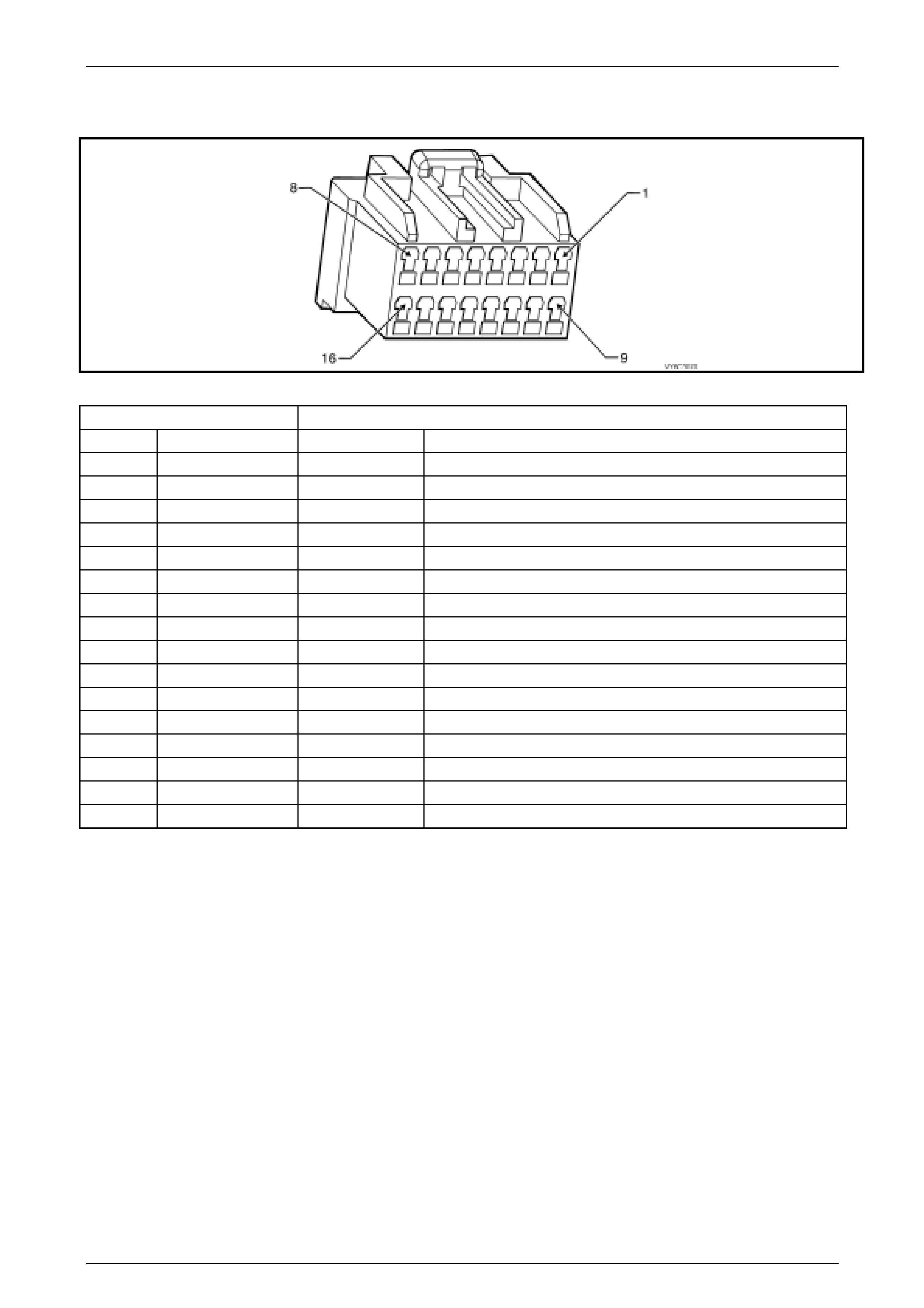
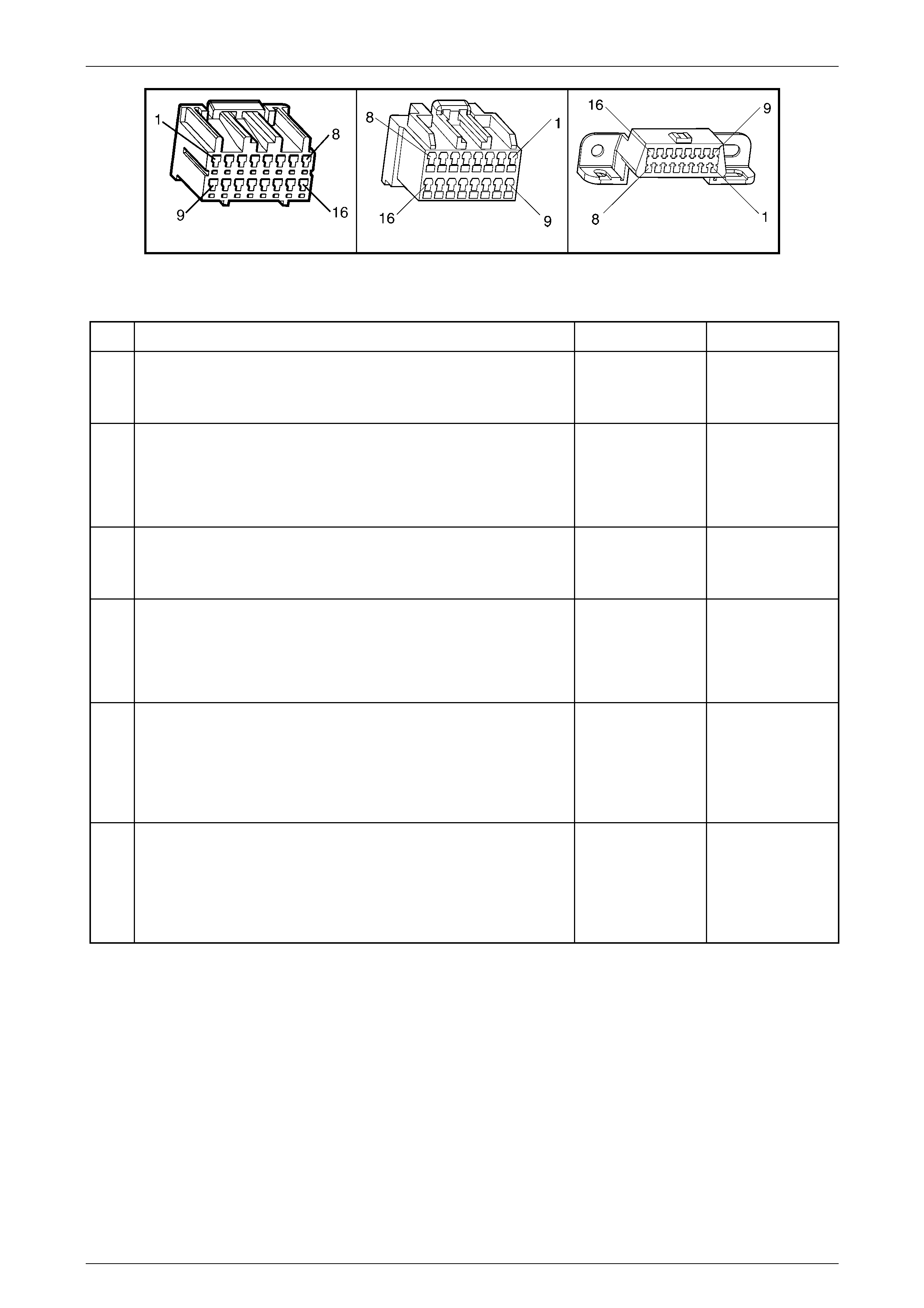
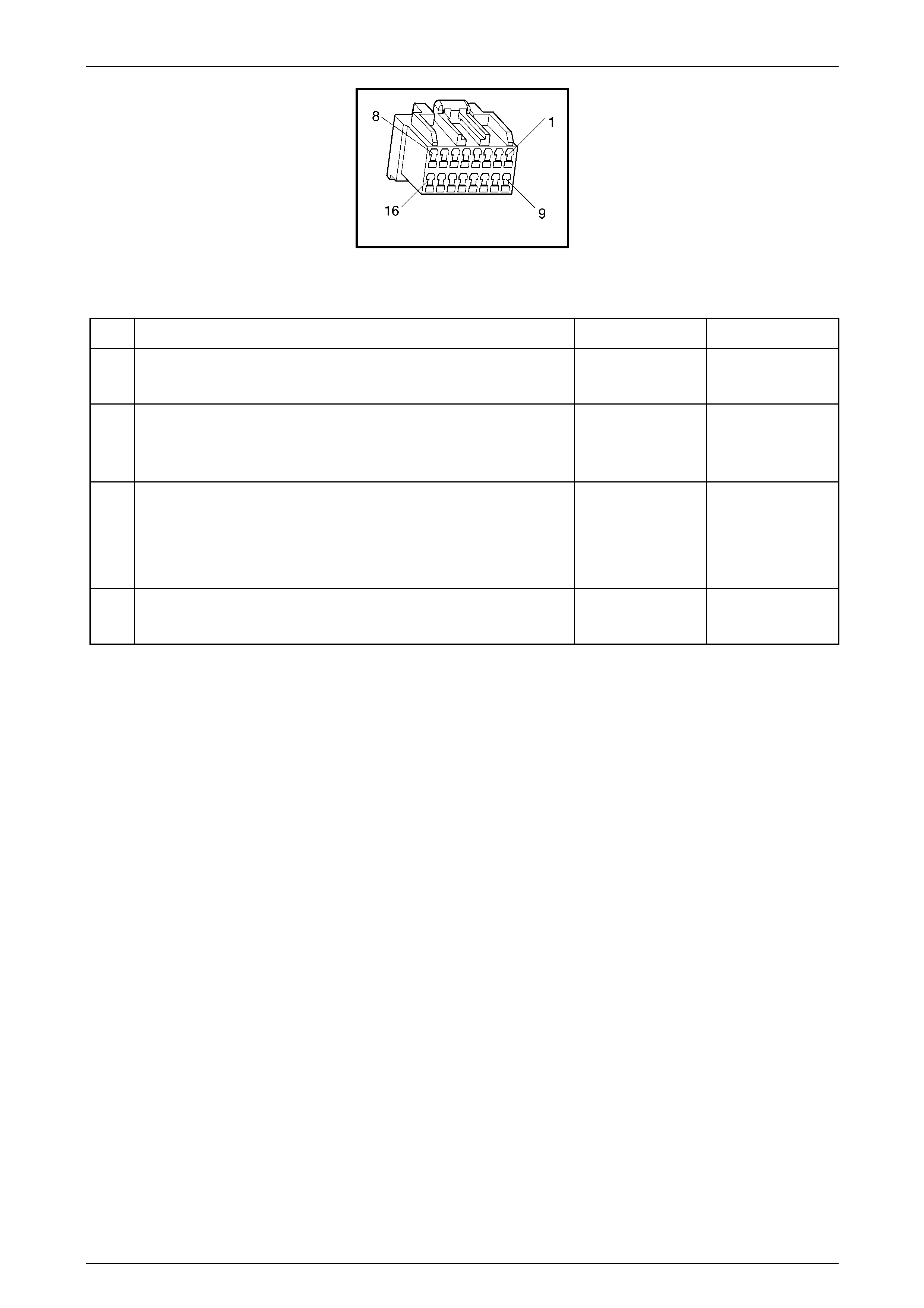
1.4 PIM Connector – A5
Figure 6C3-2A-1 – PIM Connector – A5
Connector Part Information PIM Connector A5 – X1 – 16 Pin Connector
Pin Wire Colour Circuit No. Function
1 Brown/Orange 33 Brake Fail telltale and MFD display in the Instrument
2 Green 875 ABS Off telltale and MFD display in the Instrument
3 Yellow/Red 832 Low Traction MFD display in the Instrument
4 Not Used – –
5 Not Used – –
6 Red/Black 800 UART Serial Data
7 Yellow 5072 Class II Serial Data
8 Grey/Blue 275 NSBU Lamp switch
9 Not Used – –
10 Not Used – –
11 Not Used – –
12 Not Used – –
13 Not Used – –
14 Not Used – –
15 Orange 300 Ignition Feed
16 Black/Red 450 System Ground

Powertrain Management – Diagnostic Tables – GEN III V8 Engine Page 6C3-2A-8
Page 6C3-2A-8
1.5 PIM Connector Terminal Definitions
1 Brake Fail – Acting on a signal from the ABS-TC control module on the Class 2 serial data bus, the PIM supplies a
ground to activate both the 'Brake Fail' telltale and the MFD display in the Instrument. This warning display can also
be activated by the closing of the Park Brake Switch (S181) contacts and/or the Brake Pressure Differential Switch
(S37) contacts being closed.
2 ABS Off – Acting on a signal from the ABS-TC control module on the Class 2 serial data bus, the PIM supplies a
ground to activate both the 'ABS' telltale and the MFD display in the Instrument.
3 Low Traction – Acting on a signal from the ABS-TC control module on the Class 2 serial data bus, the PIM
supplies a ground to activate the 'Lo Trac' display in the Instrument MFD.
4 Not Used
5 Not Used
6 Serial Data (UART) – This is a dedicated line for TECH 2 communications. The circuit connects the PIM, BCM,
and ABS/TCS, Instrument, OCC, SRS. TECH 2 can talk to each of these modules by sending a message to a
controller and asking only it to respond. The communication rate is at 8192 baud. The normal voltage on this circuit
is about 5 volts, but when the ignition is turned ON and the modules are communicating, the voltage will vary and if
read with a DMM may read about 2.5 volts.
7 Serial Data (Class 2) – This is dedicated line for communication between the PCM and PIM or the PCM and
TECH 2. The circuit connects between the PCM, PIM and DLC, terminal 2. TECH 2 can communicate with the
PCM by sending a message to the PCM and asking it to respond. The communication rate is at 10,400 baud and
the voltage on this circuit is normally 0 volts but is driven high to approximately 7 volts when communication is
occurring. Class II communication is prioritised, so this signal may not be constant.
8 Starter Rela y Control – When the PIM receives the proper Theft Deterrent signal from the BCM, the PIM will
supply a ground signal to the Start Relay. This will allow the vehicle to crank.
If an improper Theft Deterrent signal is sensed by the PIM, then the PIM will not supply a ground signal to the Start
Relay, and the PIM will not send a message to the PCM to allow fuel injection.
9 Not Used
10 Not Used
11 Not Used
12 Not Used
13 Not Used
14 Not Used
15 Ignition Feed –This is the power supply to the PIM from the ignition switch. The voltage should equal the battery
voltage when the key is in either the RUN, or CRANK position.
16 System Ground – This terminal should have zero volts. This circuit is connected directly to engine ground.
Powertrain Management – Diagnostic Tables – GEN III V8 Engine Page 6C3-2A-9
Page 6C3-2A-9
2 General Diagnostic Tables
2.1 On-Board Diagnostic (OBD) System
Check
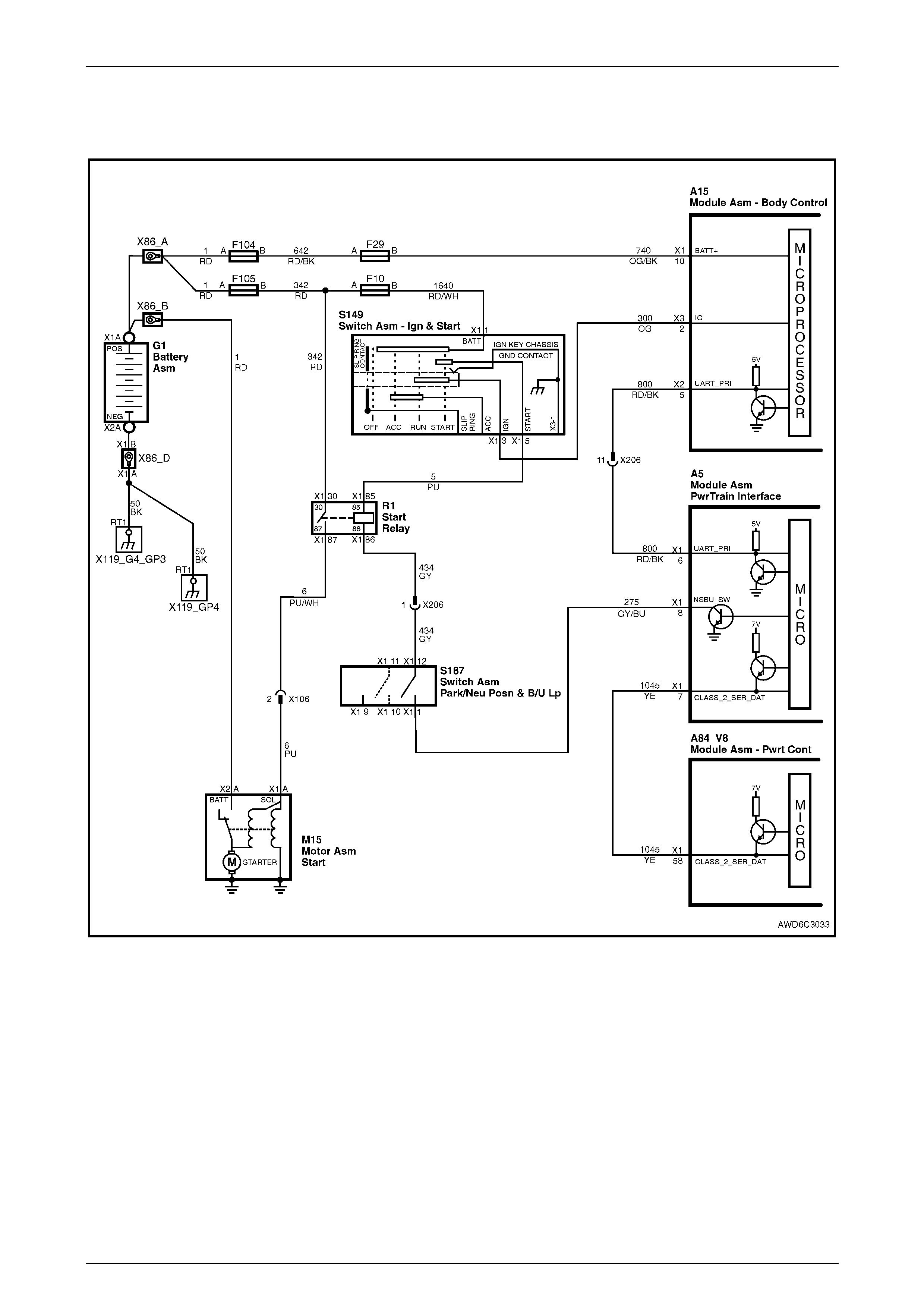
Figure 6C3-2A-2 – Data Link Connector Circuits
Circuit Description
The Powertrain OBD System Check is an organised approach to identifying a problem created by an electronic engine
control system malfunction. The Powertrain OBD System Check is the starting point for any driveability complaint
diagnosis. The Powertrain OBD System Check directs the service technician to the next logical step in diagnosing a
complaint. DO NOT PERFORM THIS CHECK IF NO DRIVEABILITY COMPLAINT EXISTS. Understanding and using
the table correctly will reduce the diagnostic time and prevent the replacement of good parts.
NOTE
This vehicle is equipped with a Powertrain
Control Module (PCM) utilising an Electrically
Erasable Programmable Read Only Memory
(EEPROM). Program the new PCM when
diagnostics call for replacement of the PCM.
Refer to PCM Replacement Programming in
Section 6C3-3 Service Operations, in the MY
2003 VY and V2 Series Service Information.
NOTE
This vehicle is equipped with a Powertrain
Interface Module (PIM). This PIM is the vehicle
serial data translator between Class II and UART
serial data.

Powertrain Management – Diagnostic Tables – GEN III V8 Engine Page 6C3-2A-10
Page 6C3-2A-10
Diagnostic Aids
• If an intermittent condition exists, inspect the PCM wiring harnesses for improper installation of electrical
components. Inspect for aftermarket theft deterrent devices, lights, and cellular phones. Ensure that no aftermarket
equipment is connected to the Class II circuit. A cellular phone signal communication may cause an intermittent
condition.
• The PIM controls the starter motor operation, while the PCM controls the fuel injector PW M. If the PCM is non-
functional, the vehicle may crank but will not start.
• If BCM DTC 7 and or DTC 17 are set, the BCM is probably causing the problem. Refer to BCM DTC tables in
Section 12J BCM, in the MY 2004 VY and V2 Series Service Information.
• If multiple DTCs are set, inspect the EFI relay for proper operation. This relay protects the battery from a parasitic
draw.
• The following components are powered by the EFI relay:
– Injectors/Ignition coils
– Transmission
– EVAP Solenoid
– MAF Sensor
– Heated Oxygen Sensors
– A/C Relay
• It is beneficial to review the Freeze Frame Data and/or Fail Records. Use the odometer information and the fail
counter in order to determine how frequently and how recently the DTC set. This information, and the other
operating conditions when the DTC set, may help diagnose an intermittent problem. Capturing the stored info
preserves data that the PCM will lose when instructed to Clear Info at the end of a diagnostic table, or if you
disconnect the PCM or replace the PCM during a diagnostic procedure. Review the captured info at the end of the
diagnostic procedure in order to catch the next DTC in the event there are multiple DTCs stored. Follow the order
of priority as listed above.
• If the engine is misfiring and no DTCs are set, refer to Cuts Out, Misses, in Section 6C3-2B Symptoms, in the MY
2003 VY and V2 Series Service Information
Test Description
NOTE
The number(s) below refer to the step number(s)
on the diagnostic table.
1 This check is used to establish if the PCM can supply Class 2 serial data for TECH 2 use. If TECH 2 can
communicate with the PCM then the PCM power and ground circuits are OK.
2 This check is to see if the PIM has received a valid theft deterrent message from the BCM. If the PIM has not
received a valid theft deterrent signal from the BCM the engine will not crank. If the vehicle will not crank, refer to
Starter Cranking Circuit to diagnose the starter cranking circuit.
3 This test determines if any DTCs are stored in the PCM memory. To determine if a DTC is current, select “DTC
Information / Failed This Ignition”.
4 This test is used to determine the cause of a "Cranks But Will Not Run," although the PCM is power ed up, a
"Cranks But Will Not Run" symptom could exist because of a PCM problem or the vehicle electrical system.
5 Look at all the parameters to determine if one is not in a normal state with just the ignition "ON" and engine
stopped. For example, look at the ECT value to see if the value is shifted above or below where it should be. If so,
refer "Diagnostic Aid Table" in DTC P0118.
6 Look at all the parameters to determine that all values are within typical ranges for normal operating temperatures
at idle. Keep in mind that a basic engine problem may alter sensor value.
Powertrain Management – Diagnostic Tables – GEN III V8 Engine Page 6C3-2A-11
Page 6C3-2A-11
A15 – X3 A5 X40
Figure 6C3-2A-3
On-Board Diagnostic System Check – Diagnostic Table
Step Action Yes No
1 1 Install TECH 2 to Data Link Connector.
2 Select V8 GEN III Engine.
Does TECH 2 display Identification Data?
Go to Step 2 Go to
Data Link Connector
Diagnosis,
in this Section.
2 1 Turn ignition “ON” and wait 5 seconds.
2 Turn ignition to “START” position.
Does engine crank?
Go to Step 3 Go to Starter
Cranking Circuit, in
6C3-2A, in the MY
2004 VY and V2
Series Service
Information.
3 1 Using TECH 2, select ”Read DTC Info Ordered by Priority”.
Are any Diagnostic Trouble Codes displayed? Refer to Applicable
DTC Table.
Start with lowest
DTC
Go to Step 4
4 Does engine start and continue to run? Go to Step 5 Go to Engine
Cranks But Will Not
Run, in 6C3-2A, in
the MY 2004 VY
and V2 Series
Service Information.
5 1 Ignition "ON", engine "STOPPED".
2 Compare TECH 2 data with typical values shown on scan data
page.
Are values normal or within typical ranges?
Go to Step 6 Refer to indicated
Component(s) –
System che ck s in
6C3-2C, in the MY
2003 VY and V2
Series Service
Information.
6 1 Ignition "ON", engine "RUNNING".
2 Compare TECH 2 data with typical values shown on scan data
page.
Are values normal or within typical ranges?
Refer to Diagnostic
Aids Refer to indicated
Component(s) –
System che ck s in
6C3-2C, in the MY
2003 VY and V2
Series Service
Information.

Powertrain Management – Diagnostic Tables – GEN III V8 Engine Page 6C3-2A-12
Page 6C3-2A-12
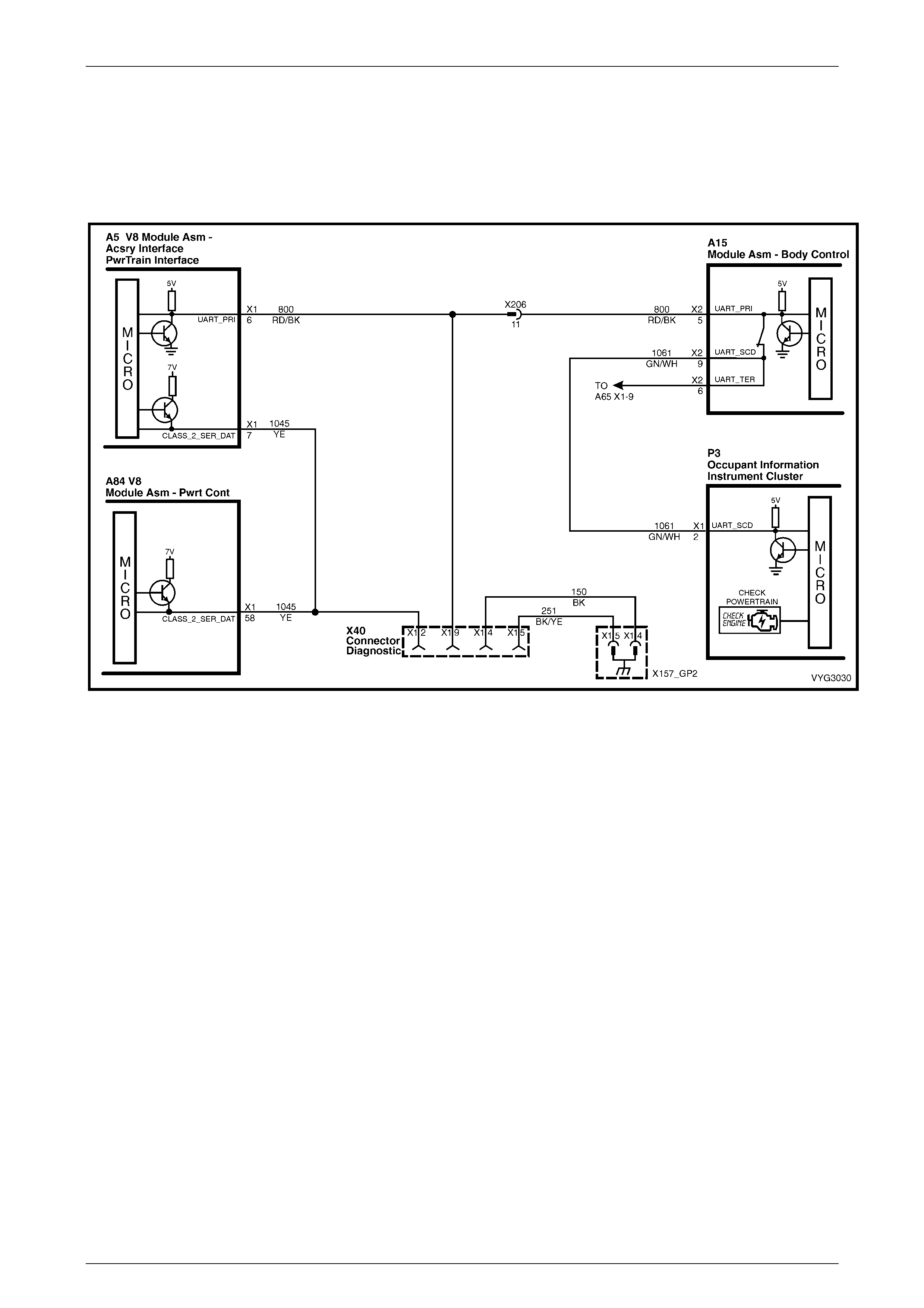
2.1 Data Link Connector Diagnosis
Figure 6C3-2A-4 – Serial Data Circuits
Powertrain Management – Diagnostic Tables – GEN III V8 Engine Page 6C3-2A-13
Page 6C3-2A-13
Circuit Description
Use a properly functioning TECH 2 with the diagnostic tables in this section. DO NOT use the ‘Clear DTC’ function
unless instructed by a diagnostic procedure.
NOTE
This vehicle is equipped with a Powertrain
Control Module (PCM) utilising an Electrically
Erasable Programmable Read Only Memory
(EEPROM). Program the new PCM when
diagnostics call for replacement of the PCM.
Refer to PCM Replacement Programming in
Section 6C3-3 Service Operations, in the MY
2004 VY and V2 Series Service Information.
Diagnostic Aids
• If there is a fault with the PIM power feed or ground circuit, TECH 2 will not communicate with the PIM.
• If BCM DTC 007 is set, it indicates there is a problem (open) in circuit 800 (UART serial data circuit) between the
BCM and the PIM.
• If PIM DTC U1001 is set, it indicates there is a problem (open, short to ground, or short to voltage) in circuit 1045
(Class II Serial data circuit) between the PIM, the PCM and/or the ABS-TC control module.
• The following Table assumes that TECH 2 is fully functional.
Test Description
NOTE
The number(s) below refer to the step number(s)
on the diagnostic table.
3 This step checks to see if the PCM is receiving all of the power supplies.
4 This step is checking the Ground circuits at the PCM.
12 This step checks to see if the Class 2 serial data circuit is shorted to ground.
13 This step checks to see if the Class 2 serial data circuit is shorted to voltage.
A84–X1 (BLUE) A84-X2 (RED)
A5 X40
Figure 6C3-2A-5

Powertrain Management – Diagnostic Tables – GEN III V8 Engine Page 6C3-2A-14
Page 6C3-2A-14
Data Link Connector – Diagnostic Table
Step Action Yes No
1 Was the “On-Board Diagnostic” (OBD) System Check performed? Go to Step 2 Go to
OBD System Check
in this Section.
2 1 Ignition ON, engine OFF.
2 Connect TECH 2 to the Diagnostic Link Connector (DLC).
Does TECH 2 power-up?
Go to Step 3 Go to Step 7
3 1 Ignition OFF.
2 Disconnect PCM connectors A84-X1 and A84-X2.
3 Ignition ON.
4 Probe each PCM battery and PCM ignition feed circuit in PCM
connectors, A84 X1-20 and A84 X1-57 (circuit 740, Orange wire)
and A84 X1-19 (circuit 300, Orange wire), using a test lamp
connected to a known good ground.
Does the test lamp illuminate at each terminal?
Go to Step 4 Go to Step 16
4 1 Ignition OFF.
2 PCM connectors still disconnected.
3 Probe PCM ground circuits with a test light connected to B+.
Is the test light ON for all ground circuits?
Go to Step 5 Go to Step 17
5 1 Ignition OFF.
2 Reconnect both PCM connectors.
3 Connect TECH 2 to the DLC.
4 Ignition ON, engine OFF.
Does TECH 2 display Engine ID Information?
Go to
OBD System Check
in this Section.
Go to Step 6
6 Will the engine crank over? Go to Step 10 Refer to
Starter Cranking
Circuit, in 6C3-2A,
in the MY 2004 VY
and V2 Series
Service Information.
7 1 Ignition ON, engine OFF.
2 Probe the DLC terminal X1-16, circuit 740 (Orange/Black wire),
with a test lamp connected to the battery ground.
Is the test lamp illuminated?
Go to Step 8 Repair circuit 740 as
required (including
fuse F29).
8 1 Probe the DLC terminal X1-4, circuit 150 (Black wire), with a test
lamp connected to B+.
Is the test lamp illuminated?
Go to Step 9 Repair circuit 150 as
required.
9 1 Inspect the TECH 2 connections to the DLC, including proper
terminal tension at the DLC.
Was a problem found?
Go to
Powertrain OBD
System Check
Table
Refer TECH 2
Operators Manual
for TECH 2 Self
Test
10 Will the engine start and run? Go to Step 18 Go to Step 14
11 1 Disconnect PCM BLUE connector A84-X1 and PIM connector
A5.
2 Check for an open in the Class II serial data circuit 1045 (Yellow
wire) between PCM BLUE connector A84-X1, terminal X1-58,
and PIM connector A5, terminal X1-7.
Was a problem found?
Repair open in
circuit 5072. Go to Step 12
12 1 Using test light connected to B+, probe the Class 2 serial data
circuit at the DLC X40, terminal X1-2, circuit 1045 (Yellow wire).
Is the test lamp illuminated?
Repair short to
ground in circuit
1045.
Go to Step 13

Powertrain Management – Diagnostic Tables – GEN III V8 Engine Page 6C3-2A-15
Page 6C3-2A-15
Step Action Yes No
13 1 Using a test light connected to a known good ground, probe the
Class 2 serial data circuit at the DLC, terminal 2, circuit 1045
(Yellow wire).
Is the test light illuminated?
Repair short to
voltage in circuit
1045. Verify repair.
Replace PCM, refer
PCM Replacement
in 6C3-3, in the MY
2004 VY and V2
Series Service
Information.
14 1 Connect the TECH 2 to the DLC.
2 Select Body / Powertrain Interface Module (PIM) / Diagnostic
Trouble Codes.
Is PIM DTC U1001 set?
Go to Step 11 Go to Step 15
15 In Step 14, were any other PIM DTC(s) set? Go to applicable
PIM DTC Table. Go to Step 18
16 1 Check for open circuit or short to ground and repair power circuit
that did not light test light.
Is action complete?
Verify Repair –
17 1 Repair open in ground circuit that did not light test light.
Is action complete? Verify Repair –
18 1 Repair open in Class 2 Serial Data circuit from DLC to PCM.
Is action complete? Verify Repair –
Powertrain Management – Diagnostic Tables – GEN III V8 Engine Page 6C3-2A-16
Page 6C3-2A-16
3 Diagnostic Tr ouble Code Tables
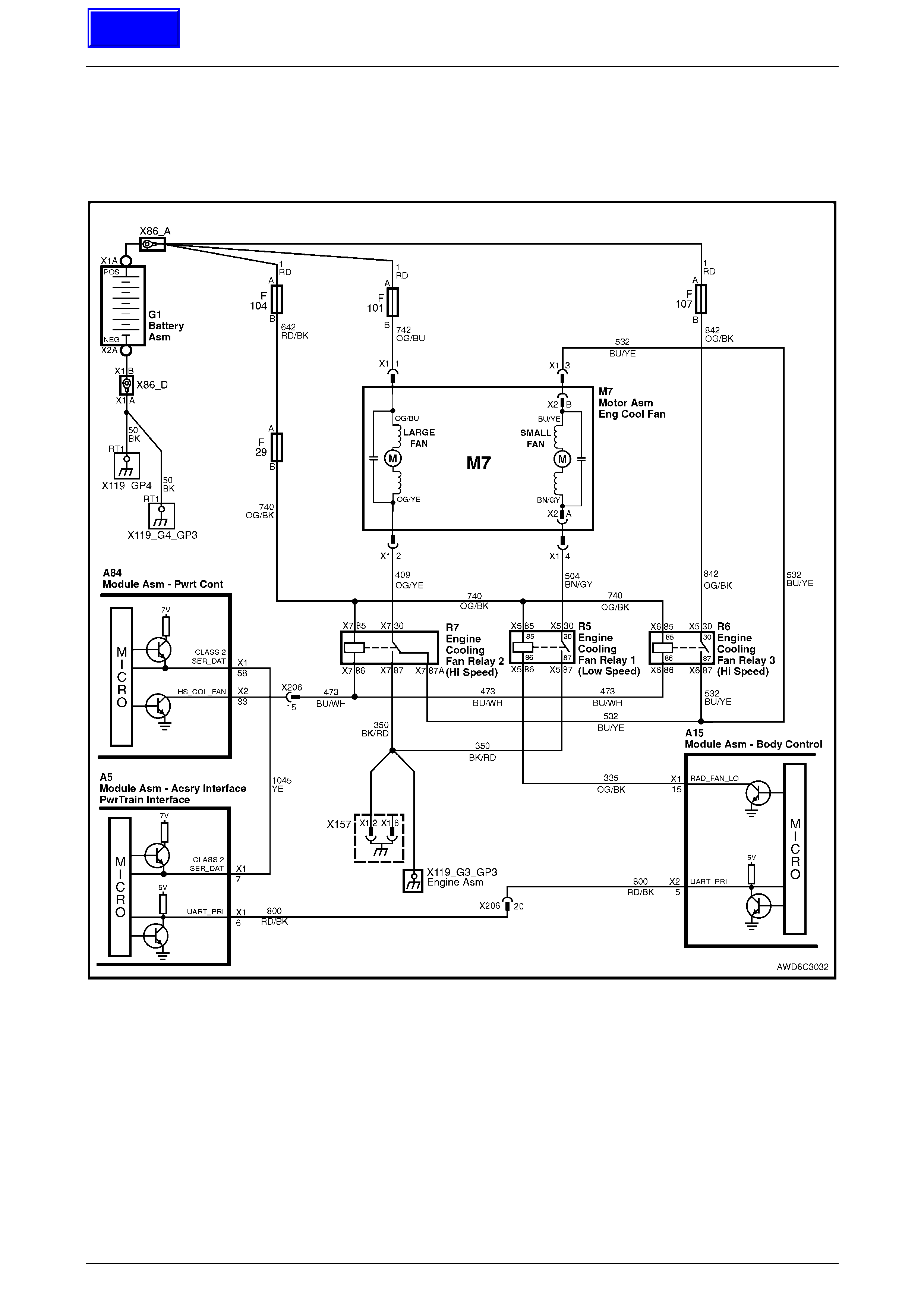
DTC P0481 – Cooling Fan High Speed Relay Control
Figure 6C3-2A-6 – Cooling Fan Circuits
Circuit Description
Battery voltage is supplied directly to all three cooling fan relay coils. The PCM controls the high speed fan relays R6 and
R7 by grounding the control circuit via an internal switch called a driver. The primary function of the driver is to supply the
ground for the controlled component. Each driver has a fault line which the PCM monitors. When the PCM commands a
component ON, the voltage of the control circuit should be low (near 0 volts). When the PCM commands the control
circuit to a component OFF, the voltage potential of the circuit should be high (near the battery voltage). If the fault
detection circuit senses a voltage other than what the PCM expected, the fault line status changes causing the DTC to
set.
The relay controls the high current flow to the cooling fans. This results in the PCM driver to only having to control the
relatively low current used by the relay.
Techline
Powertrain Management – Diagnostic Tables – GEN III V8 Engine Page 6C3-2A-17
Page 6C3-2A-17
Conditions for Running the DTC
• The engine speed is greater than 600 RPM.
• The ignition voltage is between 6.0 and 16.0 volts.
Conditions for Setting the DTC
• The PCM detects that the commanded state of the driver and the actual state of the control circuit do not match.
• The conditions must be present for a minimum of 10 seconds.
Action Taken When the DTC Sets
• The PCM activates the Check Powertrain MIL when the diagnostic runs and fails.
• The PCM records the operating conditions at the time the diagnostic fails. The PCM stores this information in the
Freeze Frame/Failure Records.
Conditions for Clearing the MIL/DTC
• The PCM deactivates the Check Powertrain MIL after the first ignition cycle that the diagnostic runs and does not
fail.
• A last test failed (current DTC) clears when the diagnostic runs and does not fail.
• Use TECH 2 to clear the MIL/DTC.
Diagnostic Aids
• Using the Freeze Frame/Failure Records data may aid in locating an intermittent condition. If you cannot duplicate
the DTC, the information included in the Freeze Frame/Failure Records data can aid in determining the distance
travelled since the DTC reported a pass and/or fail. Operate the vehicle within the same freeze frame conditions
(RPM, load, vehicle speed, temperature, etc.) that you observed. This will isolate when the DTC failed.
• For an intermittent, refer to Section 6C3-2B Symptoms, in the MY 2004 VY and V2 Series Service Information.
Test Description
NOTE
The number(s) below refer to the step number(s)
on the diagnostic table.
2 If the low speed relay (R5) is faulty, the small fan will
not operate in High Speed mode.
3/4 Listen and feel (with a finger tip on the relay) for a click
to check if relays R6 and R7 cut in and out. Command
both ON and OFF states. Repeat the commands if
necessary.
5 This check can detect a partially shorted coil which
would cause excessive current flow. Leaving the
circuit energised for 2 minutes allows the coil to warm
up. When warm, the coil may open (Amps drop to 0),
or short (goes above 0.75 Amps).
12 If you do not find any trouble in the control circuit or
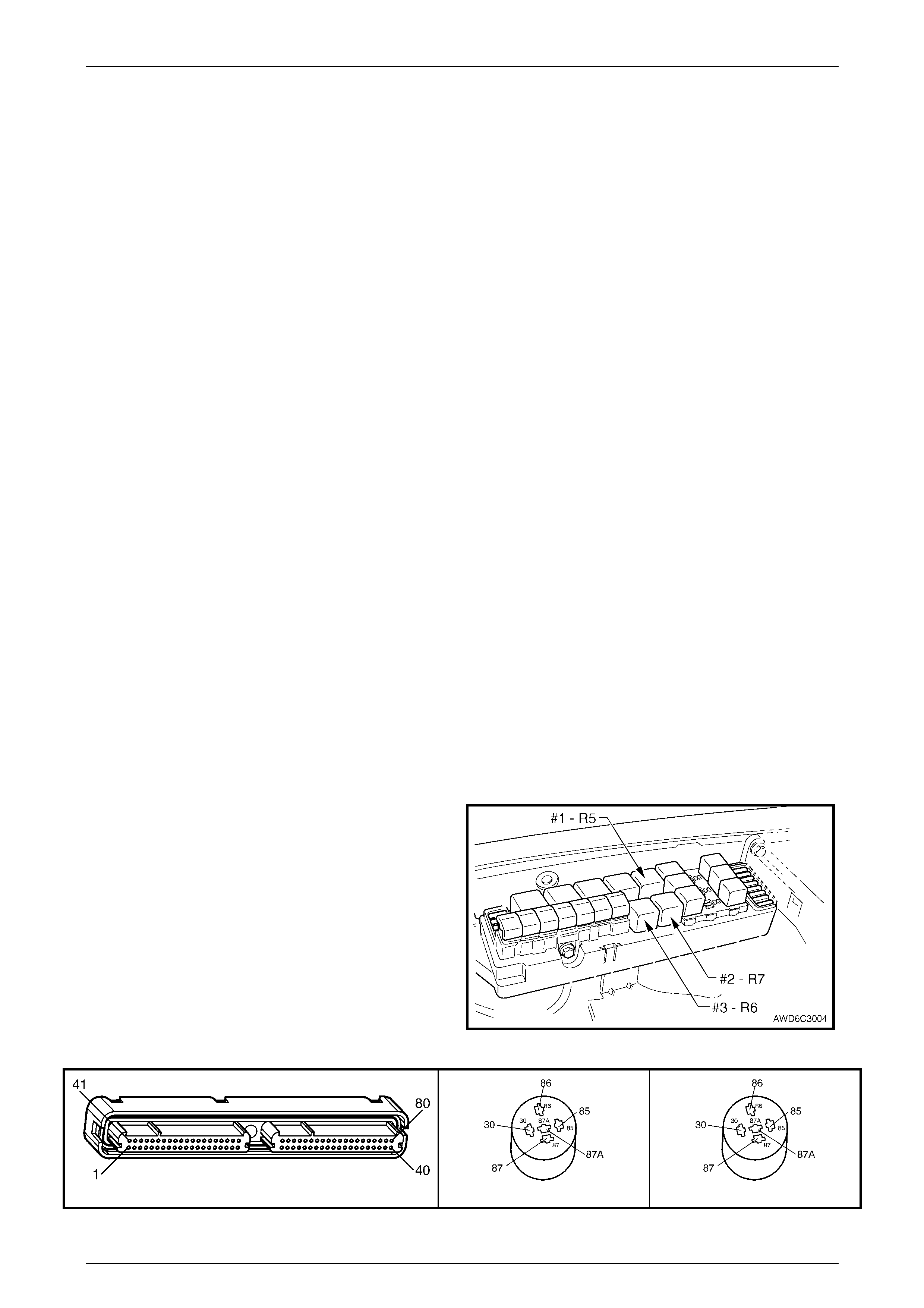
the connection at the PCM, the PCM may be faulty. Figure 6C3-2A-7 Cooling Fan Relay Locations
A84–X2 (RED) R6 (Part of X100) R7 (Part of X100)
Figure 6C3-2A-8

Powertrain Management – Diagnostic Tables – GEN III V8 Engine Page 6C3-2A-18
Page 6C3-2A-18
P0481 – Cooling Fan High Speed Relay Control – Diagnostic Table
Step Action Value(s) Yes No
1 Was the "On-Board Diagnostic" (OBD) System Check
performed? – Go to Step 2 Go to
OBD System Check
in this Section.
2 1 Ignition OFF.
2 Connect TECH 2 and, from the Main Menu, select
F3: Body / BCM / 'Miscellaneous Tests'.
3 Ignition ON, engine OFF.
4 Command the Low Speed Cooling Fan ON then
OFF.
Are both electric cooling fans activated?
– Go to Step 3 Go to 12J BCM, in
the MY 2004 VY
and V2 Series
Service Information
3 1 Using TECH 2, select F0: Engine /
F3: 'Miscellaneous Tests' / F0: Output Tests.
2 Ignition ON, engine OFF.
4 Command the High Fan ON then OFF.
Did relay 2 (R7) turn ON and OFF when commanded?
– Go to Step 4 Go to Step 7
4 1 With TECH 2 still connected, repeat step 3.
Did relay 3 (R6) turn ON and OFF when commanded? – Go to Step 5 Go to Step 7
5 1 Ignition OFF.
2 Disconnect the RED PCM connector, A84-X2.
3 Ignition ON.
4 Measure current from the relay control circuit 473
(Blue/White wire) at the RED PCM harness
connector, A84-X2, terminal X2-33, to ground for
2 minutes, using a DMM on 10 Amp scale.
Does the current draw measure less than the specified
value (but not 0)?
0.75 Amp Go to Diagnostic
Aids Go to Step 6
6 1 Ignition OFF.
2 Disconnect relays 2 (R7) and 3 (R6).
3 Measure the resistance, from the relay control
circuit 473 in the RED PCM harness connector,
A84-X2, to ground using a DMM.
Does the DMM display infinite resistance?
– Go to Step 7 Go to Step 10
7 1 Ignition OFF.
2 Disconnect relay 2 (R7).
3 Connect a test lamp between the relay control
circuit 473 and the relay B+ supply circuit 740, at
the underhood fuse and relay electrical centre,
X100, terminals X7-85 and X7-86.
4 Ignition ON.
5 Command the High Fan ON and OFF using
TECH 2.
Does the test lamp turn ON and OFF with each
command?
– Go to Step 8 Go to Step 13
8 1 Repeat Step 7 for relay 3 (R6), using terminals
X6-85 and X5-86.
Does the test lamp turn ON and OFF with each
command?
– Go to Step 9 Go to Step 13
9 1 Probe the relay B+ supply circuit 740, terminals
X7-85, then X6-85, at the underhood fuse and
relay electrical centre, X100 with a test lamp
connected to ground.
Does the test lamp turn ON, in each instance?
– Go to Step 10 Go to Step 13

Powertrain Management – Diagnostic Tables – GEN III V8 Engine Page 6C3-2A-19
Page 6C3-2A-19
Step Action Value(s) Yes No
10 1 Ignition OFF.
2 Reinstall relays 2 (R7) and 3 (R6).
3 Disconnect the PCM RED connector A84-X2.
4 Ignition ON.
5 Probe the relay control circuit 473 in the PCM
harness connector A84, terminal X2-33 with a
fused jumper wire connected to ground.
Does relay 2 (R7) operate?
– Go to Step 11 Go to Step 12
11 1 Repeat Step 10 for relay 3 (R6)
Does relay 3 (R6) operate? – Go to Step 18 Go to Step 12
12 1 Check the connections at each relay.
Did you find and correct the condition? – Go to Step 18 Go to Step 13
13 1 Check the connectio ns at the PCM .
Did you find and correct the condition? – Go to Step 18 Go to Step 17
14 1 Repair open or short to ground in the relay control
circuit 473 (Blue/White wire).
Is action complete?
– Go to Step 18 –
15 1 Repair the relay B+ supply circuit 740 (Orange/
Black wire).
Is action complete?
– Go to Step 18 –
16 1 Replace the relevant relay.
Is action complete? – Go to Step 18 –
17 1 Replace PCM. Refer to PCM Programming and
PCM/PIM/BCM Security Link Procedure, in 6C3-3
in the MY 2004 VY and V2 Series Service
Information.
Is action complete?
– Go to Step 18 –
18 1 Select the Diagnostic Trouble Code (DTC) option
and the Clear DTC Information option using TECH
2.
2 Idle the engine at the normal operating
temperature.
3 Select the Diagnostic Trouble Code (DTC) option,
the DTC Information option and the Failed This
Ignition option using TECH 2.
4 Operate the vehicle, within the Conditions for
Running the DTC, as specified in the supporting
text, if applicable.
Does TECH 2 indicate that this DTC reset?
– Go to Step 2 Go to Step 19
19 1 Using TECH 2, check for any other DTCs.
Does TECH 2 display any DTCs that you have not
diagnosed?
– Go to the applicable
DTC table System OK

Powertrain Management – Diagnostic Tables – GEN III V8 Engine Page 6C3-2A-20
Page 6C3-2A-20
DTC U1000 – No Class 2 Serial Data
Figure 6C3-2A-9 – Serial Data Circuit

Powertrain Management – Diagnostic Tables – GEN III V8 Engine Page 6C3-2A-21
Page 6C3-2A-21
Circuit Description
The Powertrain Interface Module (PIM) receives information from the Powertrain Control Module (PCM) on the Class II
serial data circuit. If there is a problem with this circuit or the PCM is not communicating, the PIM will detect this lack of
information and will set a DTC. Also, if there is a problem with the serial data circuit, performing the Powertrain OBD
System Check will lead you to the Data Link Connector Diagnosis.
Conditions for Running the DTC
• The ignition switch is ON.
• The ignition voltage is between 5.0 and 17 volts.
Conditions for Setting the DTC
• PIM does not receive any Class 2 Serial data communication for greater than five seconds.
Action Taken When the DTC Sets
• The Check Powertrain MIL will not be activated.
Conditions for Clearing the DTC
• A Last Test Failed (current DTC) clears, after the ignition has been cycled and the PIM receives Class 2 serial data.
• Use TECH 2 to clea r the DTC.
Diagnostic Aids
• The following problems may cause this DTC to set:
– Poor connections/terminal tension at the PCM.
– Poor connections/terminal tension at the PIM.
• For an intermittent, refer to Section 6C3-2B Symptoms, in the MY 2004 VY and V2 Series Service Information.
Test Description
NOTE
The number(s) below refer to the step number(s)
on the diagnostic table.
1 This test confirms that the Powertrain OBD System Check has been performed.
2 Diagnosis of this DTC will be performed using the Data Link Connector Diagnostic Table, found in the front of this
Section. If there is an open, short to ground, or short to voltage in the Class II serial data circuit between the PCM
and the PIM, this will cause PIM DTC U1000 to set.
DTC U1000 – No Class 2 Serial Data – Diagnostic Table
Step Action Yes No
1 Was the "On-Board Diagnostic" (OBD) System Check performed? Go to Step 2 Go to
OBD System Check
in this Section.
2 1 Refer to Data Link Connector Diagnosis in this Section for
diagnosis of this PIM DTC.
Is action complete?
Verify Repair –

Powertrain Management – Diagnostic Tables – GEN III V8 Engine Page 6C3-2A-22
Page 6C3-2A-22
DTC U1001 – No Serial Data from PCM
Figure 6C3-2A-10 – Serial Data Circuits

Powertrain Management – Diagnostic Tables – GEN III V8 Engine Page 6C3-2A-23
Page 6C3-2A-23
Circuit Description
The Powertrain Interface Module (PIM) receives information from the Powertrain Control Module (PCM) on the Class 2
serial data circuit. If there is a problem with this circuit or the PCM is not communicating, the PIM will detect this lack of
information and will set a DTC. Also, if there is a problem with the serial data circuit, performing the Powertrain OBD
System Check will lead you to the Data Link Connector Diagnosis.
Conditions for Running the DTC
• The ignition switch is ON.
• The ignition voltage is between 5.0 and 17 volts.
Conditions for Setting the DTC
• PIM does not receive any serial data communication from the PCM for greater than five seconds.
Action Taken When the DTC Sets
• The PIM will display the DTC only when current.
• The Check Powertrain MIL will not be activated.
Conditions for Clearing the MIL/DTC
• A Last Test Failed (current DTC) clears, after the ignition has been cycled and the PIM receives serial data from
the PCM.
• Use TECH 2 to clea r the DTC.
Diagnostic Aids
• The following problems may cause this DTC to set:
– Poor connections/terminal tension at the PCM.
– Poor connections/terminal tension at the PIM.
– For an intermittent, refer to Section 6C3-2B Symptoms, in the MY 2004 VY and V2 Series Service
Information.
Test Description
NOTE
The number(s) below refer to the step number(s)
on the diagnostic table.
1 This test confirms that the Powertrain OBD System Check has been performed.
2. Diagnosis of this DTC will be performed using the Data Link Connector Diagnostic Table, found in this Section. If
there is an open, short to ground, or short to voltage in the Class 2 serial data circuit between the PCM and the
PIM, this will cause PIM DTC U1001 to set.
DTC U1001 – No Serial Data from the PCM – Diagnostic Table
Step Action Yes No
1 Was the "On-Board Diagnostic" (OBD) System Check performed? Go to Step 2 Go to
OBD System Check
in this Section.
2 1 Refer to Data Link Connector Diagnosis in this Section for
diagnosis of this PIM DTC.
Is action complete?
Verify Repair –

Powertrain Management – Diagnostic Tables – GEN III V8 Engine Page 6C3-2A-24
Page 6C3-2A-24
DTC U1043 – No Serial Data from ABS-TC
Figure 6C3-2A-11 – Serial Data Circuits

Powertrain Management – Diagnostic Tables – GEN III V8 Engine Page 6C3-2A-25
Page 6C3-2A-25
Circuit Description
The Powertrain Interface Module (PIM) receives information from the ABS/TC Control Module on the Class II serial data
circuit. If there is a problem with this circuit or the ABS/TC control module is not communicating, the PIM will detect this
lack of information and will set a DTC. Also, if there is a problem with the serial data circuit, performing the Powertrain
OBD System Check will lead you to the Data Link Connector Diagnosis
Conditions for Running the DTC
• The ignition switch is ON.
• The ignition voltage is between 5.0 and 17 volts.
Conditions for Setting the DTC
• PIM does not receive any Class II data communication from the ABS/TC control module for greater than five (5)
seconds.
Action Taken When the DTC Sets
• The Check Powertrain MIL will not be activated.
• The ABS MIL will be activated.
• Brake fail lamp will be activated.
Conditions for Clearing the MIL/DTC
• A Last Test Failed (current DTC) clears, after the ignition has been cycled and the PIM receives serial data from
the ABS-TC control module.
• Use TECH 2 to clear the MIL/DTC.
Diagnostic Aids
• The following problems may cause this DTC to set:
– Poor connections/terminal tension at the ABS/TC Control Module.
– Poor connections/terminal tension at the PIM.
• For an intermittent, refer to Section 6C3-2B Symptoms, in the MY 2004 VY and V2 Series Service Information.
Test Description
NOTE
The number(s) below refer to the step number(s)
on the diagnostic table.
1 This test confirms that the Powertrain OBD System Check has been performed.
2 This test confirms if the DTC is current.
3. If DTC U1064 is set, this DTC should be diagnosed first.
4 This test confirms that the ABS/TC is powered up and able to communicate.
5 If ABS-TC normal mode data is not available, then the ABS-TC module should be replaced.

Powertrain Management – Diagnostic Tables – GEN III V8 Engine Page 6C3-2A-26
Page 6C3-2A-26
DTC U1043 – No Serial Data from ABS-TC – Diagnostic Table
Step Action Yes No
1 Was the "On-Board Diagnostic" (OBD) System Check performed? Go to Step 2 Go to
OBD System Check
in this Section.
2 1 From the TECH 2 PIM Diagnostic Trouble Code menu, select
the Clear DTC option and clear PIM DTCs.
2 Ignition On, Engine Off for at least 10 seconds.
Does TECH 2 indicate that this DTC reset?
Go to Step 3 DTC is Intermittent.
Refer Diagnostics
Aids.
3 Is PIM DTC U1000 Set? Go to DTC U1000
in this Section. Go to Step 4
4 1 From the TECH 2 application menu select Chassis/ABS/TC.
Does TECH 2 Display ABS-TC ID Informat ion ? Go to Step 5 Refer ABS - TC
Diagnosti cs in 5B
ABS-TC, in the
MY 2004 AWD
Wagon S ervice
Information.
5 1 From the TECH 2 ABS-TC Menu Select Normal Mode.
Does TECH 2 display Normal Mode data? Go to Step 6 Replace ABS-TC
control modu le.
Refer 5B ABS-TC,
in the MY 2004
A WD Wagon
Service Information.
6 1 Replace PIM. Refer to PIM Replace and PCM/PIM/BCM
Security Link Procedure, in 6C3-3 Service Operations, in the MY
2004 VY and V2 Series Service Information.
Is action complete?
Verify Repair –
Powertrain Management – Diagnostic Tables – GEN III V8 Engine Page 6C3-2A-27
Page 6C3-2A-27
DTC U1064 – No Serial Data from BCM
Figure 6C3-2A-12 – Serial Data Circuits

Powertrain Management – Diagnostic Tables – GEN III V8 Engine Page 6C3-2A-28
Page 6C3-2A-28
Circuit Description
The Powertrain Interface Module (PIM) receives information from the BCM on the UART serial data circuit. If there is a
problem with this circuit or the BCM is not communicating, the PIM will detect this lack of information and will set a DTC.
Also, if there is a problem with the serial data circuit, performing the Powertrain OBD System Check will lead you to the
Data Link Connector Diagnosis.
Conditions for Running the DTC
• The ignition switch is ON.
• The ignition voltage is between 5.0 and 17 volts
Conditions for Setting the DTC
• PIM does not receive any serial data communication from the BCM for greater than 10 seconds.
Action Taken When the DTC Sets
• The Check Powertrain MIL will not be activated.
Conditions for Clearing the DTC
• A Last Test Failed (current DTC) clears, after the ignition has been cycled and the PIM receives serial data from
the BCM.
• Use TECH 2 to clea r the DTC.
Diagnostic Aids
• The following problems may cause this DTC to set:
– Poor connections/terminal tension at the BCM.
– Poor connections/terminal tension at the PIM.
• For an intermittent, refer to Section 6C3-2B Symptoms, in the MY 2004 VY and V2 Series Service Information.
Test Description
NOTE
The number(s) below refer to the step number(s)
on the diagnostic table.
1 This test confirms that the Powertrain OBD System Check has been performed.
2 This test confirms if the DTC is current.
3 This test confirms that the BCM is powered up and able to communicate.
4. If BCM normal mode data is not available then the BCM should be replaced.

Powertrain Management – Diagnostic Tables – GEN III V8 Engine Page 6C3-2A-29
Page 6C3-2A-29
DTC U1064– No Serial Data from BCM – Diagnostic Table
Step Action Yes No
1 Was the "On-Board Diagnostic" (OBD) System Check performed? Go to Step 2 Go to
OBD System Check
in this Section.
2 1 From the TECH 2 PIM Diagnostic Trouble Code menu, select
the Clear DTC option and clear PIM DTCs.
2 Ignition On, Engine Off for at least 10 seconds.
Does TECH 2 indicate that this DTC reset?
Go to Step 3 DTC is Intermittent.
Refer Diagnostics
Aids.
3 1 From the TECH 2 application menu select Body/BCM.
Does TECH 2 Display BCM ID Information? Go to Step 4 Go to BCM
Diagnostics. Refer
to 12J BCM, in the
MY 2004 VY and V2
Series Service
Information.
4 1 From the TECH 2 BCM Menu Select Normal Mode.
Does TECH 2 display Normal Mode data? Go to Step 5 Replace BCM.
Refer to 12J BCM,
in the MY 2004 VY
and V2 Series
Service Information.
5 1 Replace PIM. Refer to PIM Replace and PCM/PIM/BCM
Security Link Procedure, in 6C3-3 SERVICE OPERATIONS.
Is action complete?
Verify Repair –
Powertrain Management – Diagnostic Tables – GEN III V8 Engine Page 6C3-2A-30
Page 6C3-2A-30
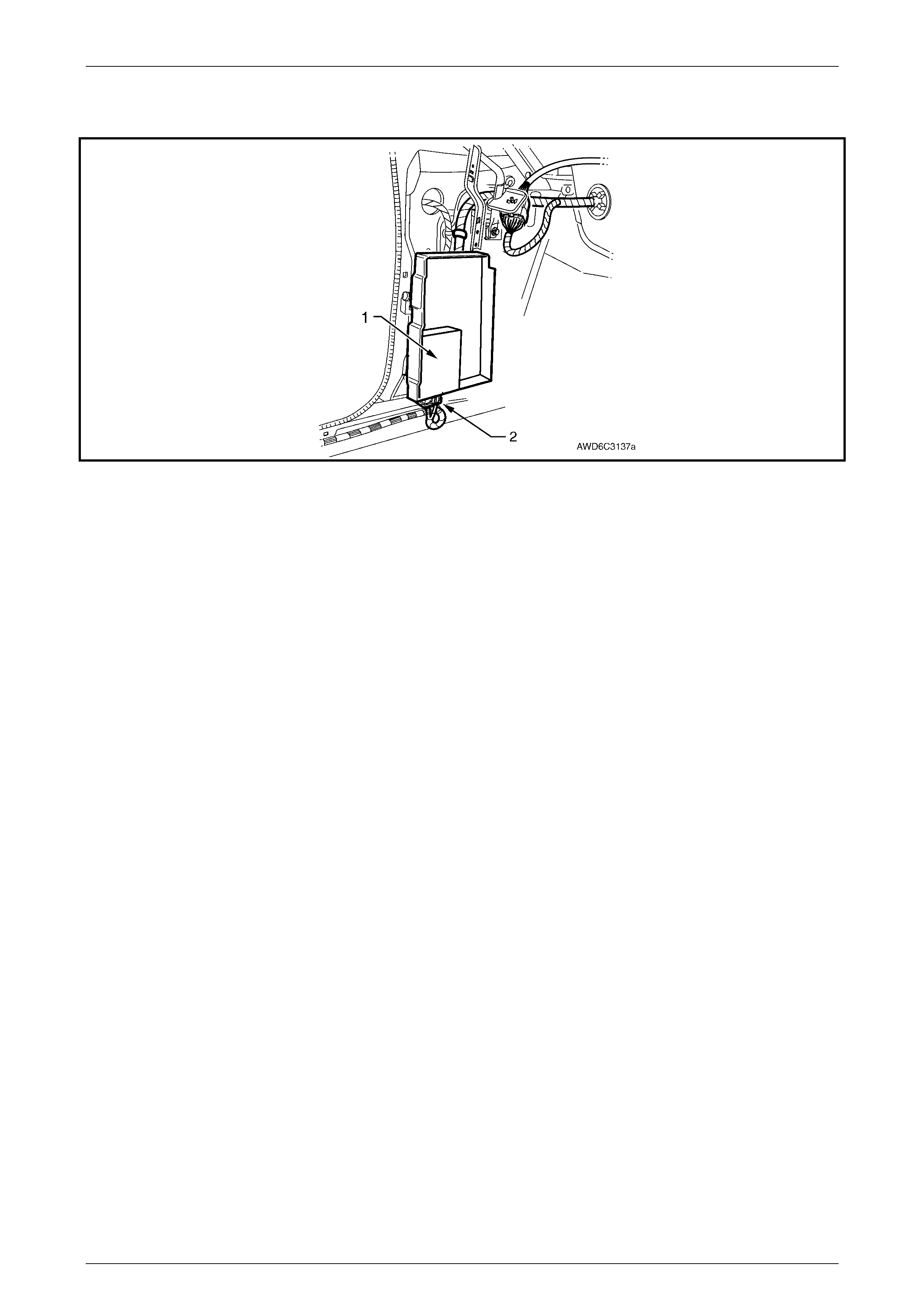
DTC B1009 – EEPROM Checksum Error
Figure 6C3-2A-13 – Powertrain Interface Module Location
Legend
1 Powertrain Interf ace Module (PIM) 2 PIM Wiring Harness Connector
Circuit Description
The PIM EEPROM contains data which controls the operation of the PIM. The PIM continuously checks the integrity of
this data. If the PIM determines that the data has been compromised DTC B1009 will be set.
Conditions for Running the DTC
• The ignition switch is in the ‘CRANK’ or ‘ON’ position.
Conditions for Setting the DTC
• The PIM is unable to correctly read data from its memory.
Action Taken When the DTC Sets
• The Check Powertrain MIL will not be activated.
Conditions for Clearing the DTC
• A Last Test Failed (current DTC) clears, after the ignition has been cycled and the PIM is able to correctly read
data.
• Use TECH 2 to clea r the DTC.
Diagnostic Aids
• For an intermittent, refer to Section 6C3-2B Symptoms, in the MY 2003 VY and V2 Series Service Information.
Test Description
NOTE
The number(s) below refer to the step number(s)
on the diagnostic table.
2 This DTC indicates an internal PIM problem.
Powertrain Management – Diagnostic Tables – GEN III V8 Engine Page 6C3-2A-31
Page 6C3-2A-31
A5
Figure 6C3-2A-14
DTC B1009 – EEPROM Checksum Error– Diagnostic Table
Step Action Yes No
1 Was the "On-Board Diagnostic" (OBD) System Check performed? Go to Step 2 Go to
OBD System Check
in this Section.
2 1 Replace PIM. Refer to PIM Replace and PCM/PIM/BCM
Security Link Procedure, in 6C3-3 Service Operations, in the MY
2004 VY and V2 Series Service Information.
Is action complete?
Go to Step 3 –
3 1 Select the Diagnostic Trouble Code (DTC) option and the Clear
DTC Information option, using TECH 2.
2 Idle the engine at normal operating temperature.
3 Select the Diagnostic Trouble Code (DTC) option using TECH 2.
Does TECH 2 indicate that this DTC reset?
Go to Step 2 Go to Step 4
4 1 Using TECH 2, check for any other DTCs.
Does TECH 2 display any DTCs that you have not diagnosed? Go to Diagnostic
Trouble Code
(DTC) List
System OK
Powertrain Management – Diagnostic Tables – GEN III V8 Engine Page 6C3-2A-32
Page 6C3-2A-32
DTC B3027 – Starter Enable Circuit Range /
Performance
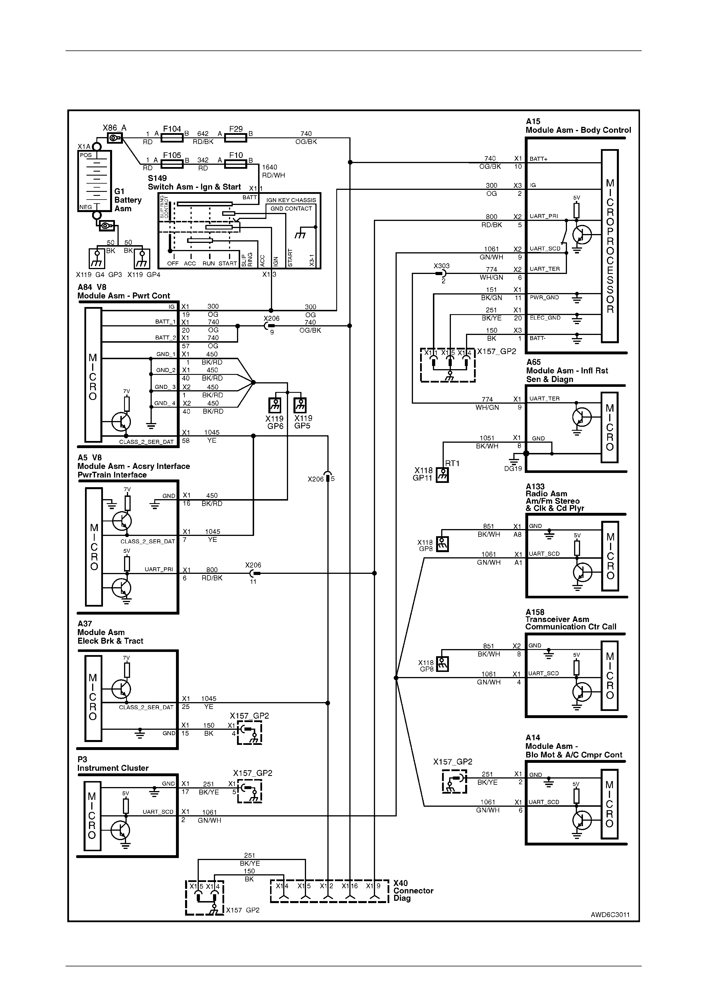
Figure 6C3-2A-11 – Starter Relay Circuit
Circuit Description
When the key is turned to the crank position, power is supplied to the starter relay terminal X1 85. After receiving the
proper theft deterrent signal from the BCM, the Powertrain Interface Module (PIM), will supply a ground signal to the
starter relay, terminal X1 86. This will energise the starter relay and allow the starter motor to operate. If there is a
problem with the starter relay coil (shorted internally) or the starter relay control circuit (shorted to voltage) that is allowing
12 volts on the starter relay control circuit, this will cause excessive current flow through the PIM causing DTC B3027 to
set.
Conditions for Running the DTC
• The ignition switch is in the crank position.
• The ignition voltage is between 5.0 and 17 volts.
Powertrain Management – Diagnostic Tables – GEN III V8 Engine Page 6C3-2A-33
Page 6C3-2A-33
Conditions for Setting the DTC
• PIM detects excessive current through the starter relay control circuit.
Action Taken When the DTC Sets
• The PIM will shut down the starter relay control circuit.
• The Check Powertrain MIL will not be activated.
Conditions for Clearing the DTC
• A Last Test Failed (current DTC) clears, after the ignition has been cycled and the PIM no longer detects excessive
current flow through the starter relay circuit.
• Use TECH 2 to clea r the DTC.
Diagnostic Aids
• The following may cause an intermittent:
– Incorrectly routed harness.
– Rubbed through wire insulation.
– Broken wire inside the insulation.
• For an intermittent, refer to Section 6C3-2B Symptoms, in the MY 2004 VY and V2 Series Service Information
Test Description
NOTE
The number(s) below refer to the step number(s)
on the diagnostic table.
2 This test checks to see if the relay is causing the high voltage problem.
5 This test checks to see if the PIM is causing the problem.
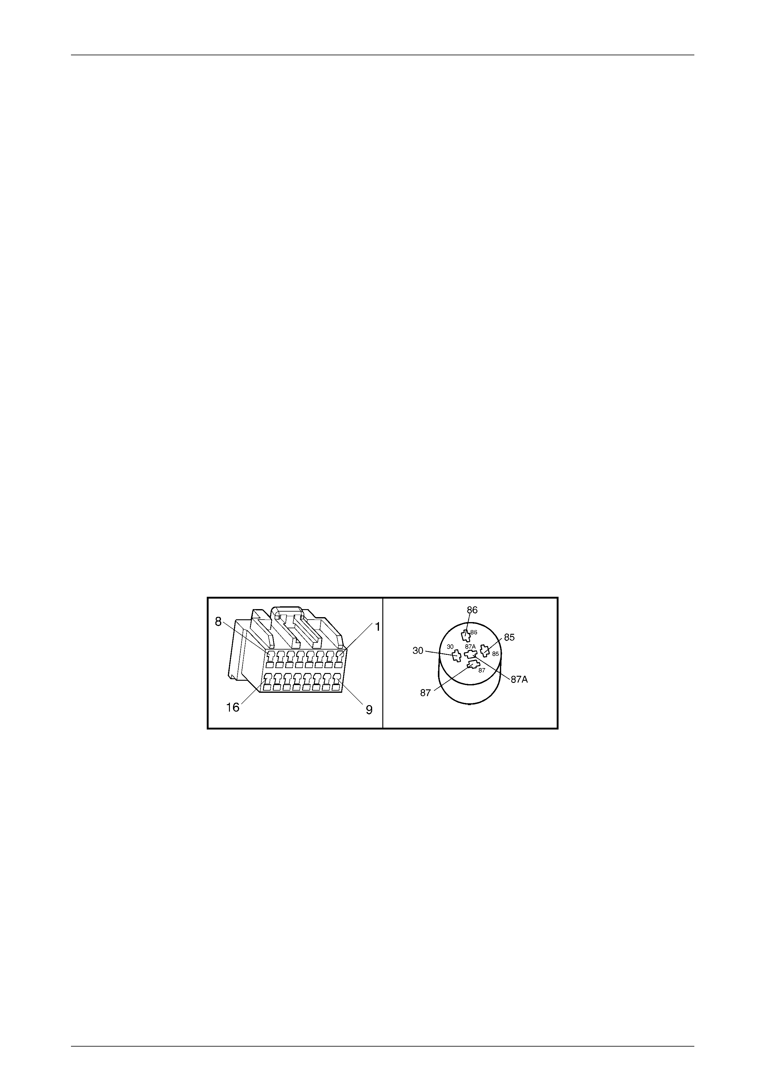
A5 X1 (Part of X100)
Figure 6C3-2A-15

Powertrain Management – Diagnostic Tables – GEN III V8 Engine Page 6C3-2A-34
Page 6C3-2A-34
DTC B3027– Starter Relay Circuit Range/Performance – Diagnostic Table
Step Action Yes No
1 Was the "On-Board Diagnostic" (OBD) System Check performed? Go to Step 2 Go to
OBD System Check
in this Section.
2 1 Ignition OFF.
2 Disconnect the PIM harness connector, A5.
3 Ignition ON.
4 Using a test light connected to ground, probe PIM harness
connector terminal for starter relay control.
Does test light illuminate?
Go to Step 3 Go to Step 6
3 1 While the test light is still connected to PIM harness c onnector,
disconnect the starter relay.
Is test light still illuminate?
Go to Step 4 Go to Step 5
4 1 Repair short to voltage in the starter relay control circuit.
Is action complete? Verify Repair –
5 1 Replace starter relay, R1.
Is action complete? System OK –
6 1 Ignition OFF.
2 Reconnect the PIM harness connector, A5.
3 Crank engine.
4 Using TECH 2, check to see if PIM DTC B3027 has reset.
Did PIM DTC B3027 reset?
Go to Step 7 System OK
7 1 Replace PIM. Refer to PIM Replace and PCM/PIM/BCM
Security Link Procedure, in 6C3-3 Service Operations, in the MY
2004 VY and V2 Series Service Information.
Is action complete?
System OK –