
Powertrain Management Functional Checks – Gen III V8 Engine Page 6C3-2C-1
Page 6C3-2C-1
Section 6C3 2C
Powertrain Management Functional Checks –
GEN III V8 Engine
ATTENTION
Before performing any Service Operation or other procedure described in this Section, refer to Section 00
Cautions And Notes for correct workshop practices with regard to safety and/or property damage.
1 General Information............................................................................................................................... 2
2 Functional Checks................................................................................................................................. 3
GEN III V8 PCM – Engine Cooling Fan Control....................................................................................................3
Circuit Description...............................................................................................................................................3
Test Description..................................................................................................................................................4
GEN III V8 PCM – Engine Cooling Fan Control..................................................................................................5
3 Specifications......................................................................................................................................... 9
Engine Cooling...................................................................................................................................................9

Powertrain Management Functional Checks – Gen III V8 Engine Page 6C3-2C-2
Page 6C3-2C-2
1 General Information
With the following exception, MY 2004 AWD Wagon, Powertrain Management Functional Checks carries over from MY
2003 VY and V2 Series Service Information, Section 6C3-2C Powertrain Management Functional Checks - GEN III V8
Engine. Therefore, for all Functional Checks not contained within this Section, refer to Section 6C3-2C Powertrain
Management Functional Checks - GEN III V8 Engine in the MY 2003 VY and V2 Series Service Information.
While the engine cooling system fitted to the MY 2004 AWD Wagon is similar to that fitted to MY 2003 VY Series Cab
Chassis with the GEN III V8 engine, the Functional Checks contained here, have been updated.
The following pages are to be used when there is a customer complaint and there are no diagnostic trouble codes set, or
one or more of the TECH 2 data values are not within the typical values. They are also to be used when instructed from a
DTC table. Before using these tables however, you should refer to Section 6C3-2B Symptoms in the MY 2003 VY and
V2 Series Service Information, which may also direct you to using this Section.
The purpose of these tables is to diagnose Powertrain Control Module (PCM) controlled components or sub-systems that
do not have diagnostic trouble codes assigned to them. Another purpose of these tables is for Technicians who feel
confident that a particular part of the sub-system is not operating properly and wants only to check that particular item for
proper operation without going through lengthy diagnostic procedures.
Powertrain Management Functional Checks – Gen III V8 Engine Page 6C3-2C-3
Page 6C3-2C-3
2 Functional Checks
GEN III V8 PCM – Engine Cooling Fan Control
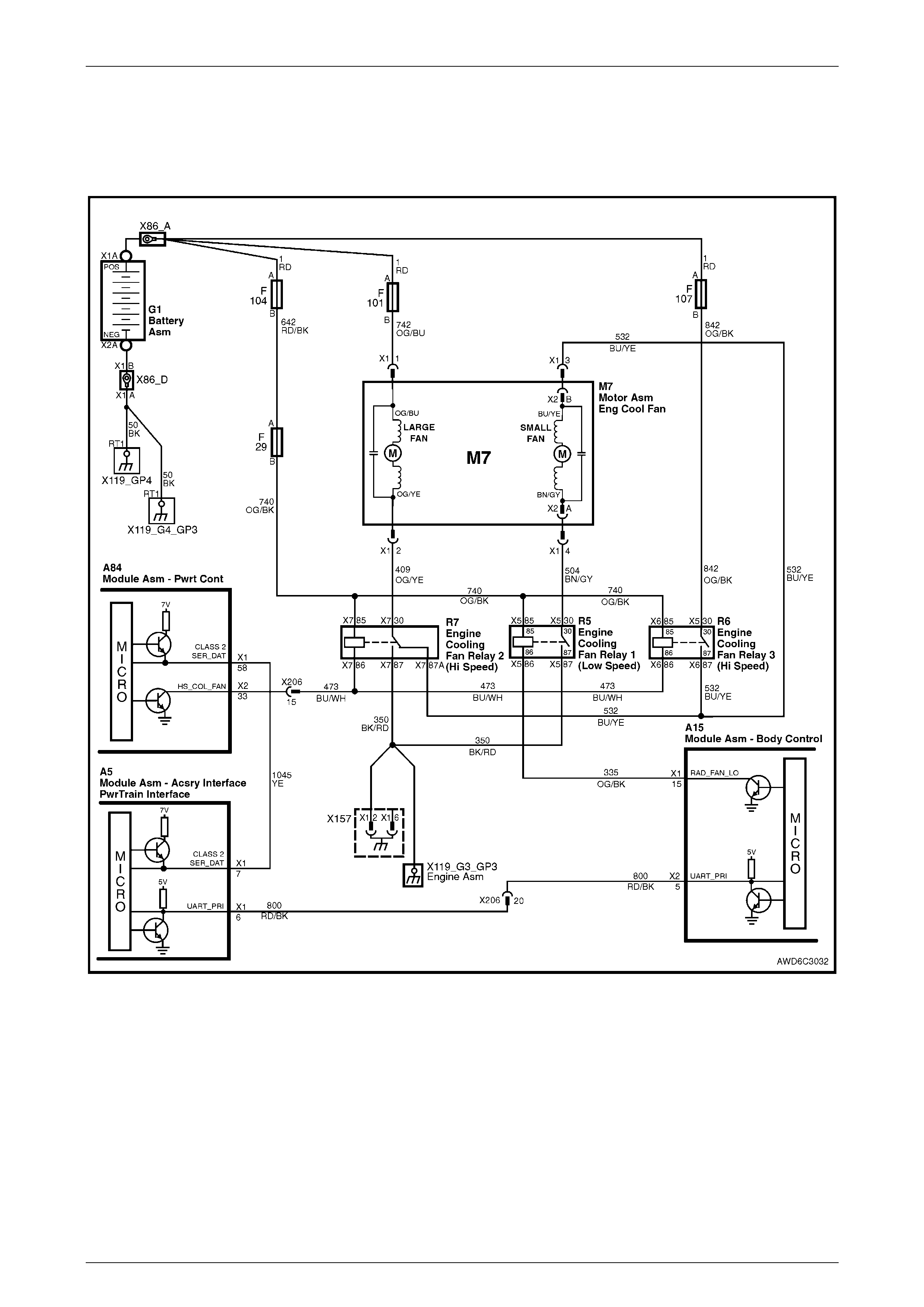
Figure 6C3-2C-1 – Cooling Fan Circuits
Circuit Description
The GEN III V8 engine has two, two speed electric engine cooling fan motors which provide the primary means of
moving air through the radiator. The cooling fans are used to cool engine coolant flowing through the radiator and the
refrigerant flowing through the A/C condenser.
The engine cooling fan stage 2 relays (R6 & R7) are controlled by the PCM. The PCM controls the ground path for the
engine cooling fan stage 2 relays.
The stage 1 operation of the engine cooling fans is controlled by the PCM through serial data communication to the
BCM. The BCM controls the ground path for the engine cooling fan stage 1 relay (R5).
All three relays in the cooling fan control circuit are used to control the ground paths to the electric motors that drive both
fans.
Powertrain Management Functional Checks – Gen III V8 Engine Page 6C3-2C-4
Page 6C3-2C-4
Stage 1 Engine Cooling Fan Operation
The engine cooling fan stage 1 relay (R5) is energised by the BCM providing the ground. The PCM determines when to
enable the engine cooling fan stage 1 operation based on inputs from the A/C request signal, vehicle speed and engine
coolant temperature. The engine cooling stage 1 relay will be turned ON when:
A/C request indicated (YES) and;
Vehicle speed less than 30 km/h
OR
Coolant temperature is greater than a specified value and will remain on until coolant temperature reduces to a
predetermined value.
Stage 2 Engine Cooling Fan Operation
The engine cooling fan stage 2 operation is controlled by the PCM based on inputs from the Engine Coolant
Temperature Sensor (ECT) and the A/C Pressure Sensor. The PCM will only turn ON the stage 2 engine cooling fan
relays (R6 and R7) if the stage 1 engine cooling fan relay (R5) has been switched ON and the following conditions are
satisfied.
• There is a BCM message response fault, which will cause a DTC to set.
• An engine coolant temperature sensor failure is detected, such as DTC P0117, P0118, P1114, P1115.
• Coolant temperature greater than a specified value.
• A/C pressure greater than a specified value.
If the stage 1 cooling fan relay (R5) was OFF when the criteria was met to turn the stage 2 cooling fans ON, the cooling
fan stage 2 relays (R6 and R7) will operate 5 seconds after the stage 1 cooling fan is activated. The A/C Refrigerant
Pressure Sensor can also enable the engine cooling fan stage 2 relays. The A/C Refrigerant Pressure Sensor will
provide a signal to the PCM when A/C pressure becomes too high; approximately 2,600 kPa.
For replacement of either cooling fan motor, refer to 2.15 Cooling Fans and Shroud Assembly in Section 6B3 Engine
Cooling - GEN III V8 Engine, the MY 2003 VY and V2 Series Service Information.
Test Description
NOTE
The number(s) below refer to the step number(s)
on the diagnostic table.
2 This entire diagnostic procedure must begin with a cold engine – at ambient air temperature. If the coolant is hot
when diagnosis is performed, replacement of good parts will result. The fans should not be running if engine
coolant temperature is less than 99° C and air conditioning is not ON.
3 With relay 1 (R5) removed, the ground path for the fan operation is open, so no fans should operate.
7 Listen and feel (with a finger tip on the relay) for a click to check if relays R6 and R7 cut in and out. Command both
ON and OFF states. Repeat the commands if necessary.
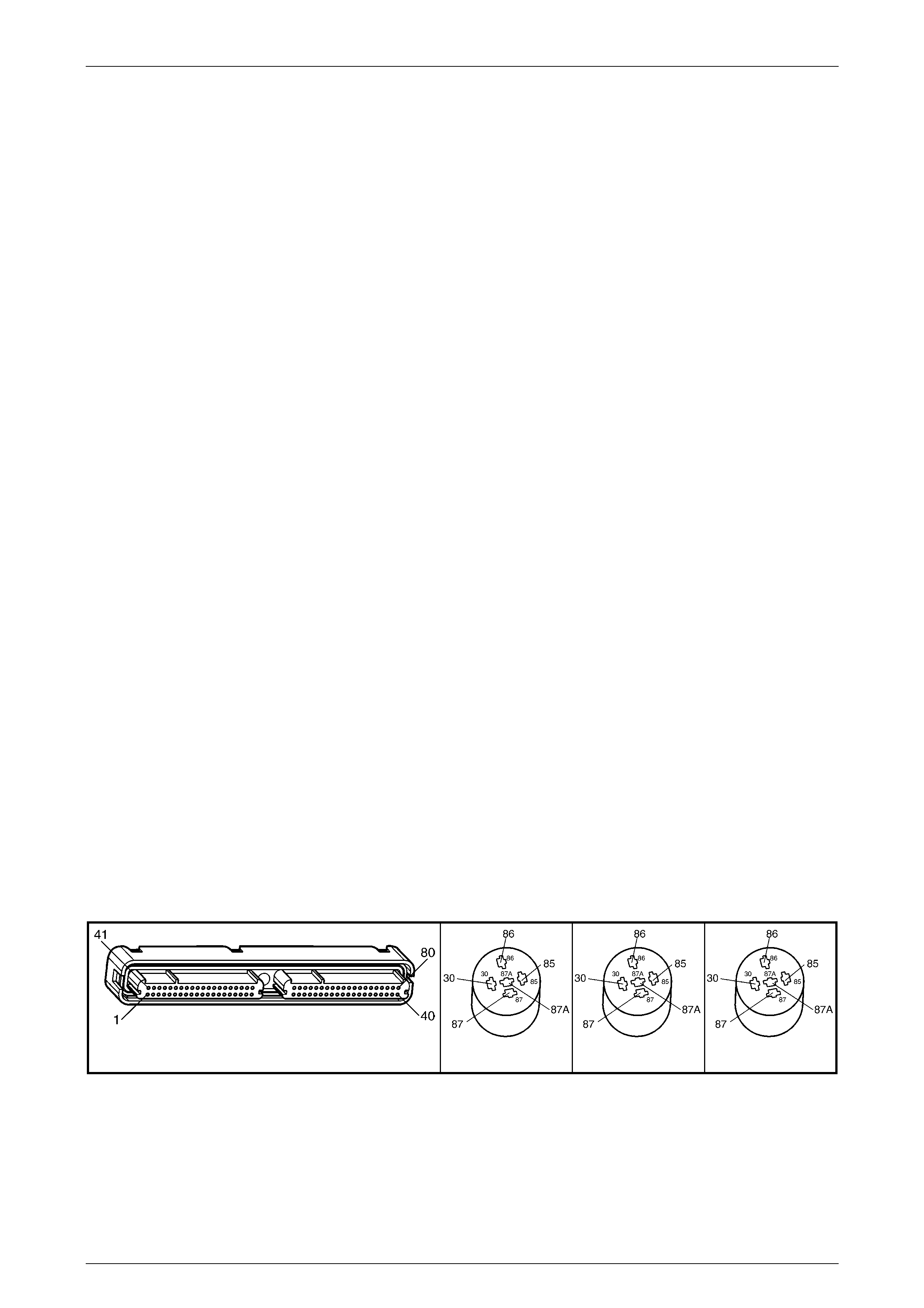
A84–X2 (RED) R5 (Part of X100) R6 (Part of X100) R7 (Part of X100)
Figure 6C3-2C-2
Powertrain Management Functional Checks – Gen III V8 Engine Page 6C3-2C-5
Page 6C3-2C-5
GEN III V8 PCM – Engine Cooling Fan Control
Step Action Value(s) Yes No
1 Was the "On-Board Diagnostic" (OBD) System Check
performed – Go to Step 2 Go to
OBD System
Check.
Refer to 6C3-2A
Diagnostic Tables.
2 1 Ignition ON, engine OFF.
2 Engine coolant temperature below 99° C.
Are both engine cooling fans running?
– Go to Step 3 Go to Step 8
3 1 Ignition OFF
2 Remove cooling fan relay 1 (R5).
3 Ignition ON
Do both fans continue to run?
– Go to Step 4 Go to Step 5
4 1 Check for a short to ground in circuit 504.
Was a problem found and corrected? – Go to Step 6 Go to Step 5
5 1 Ignition OFF.
2 Check for short to ground in circuit 335.
Was a short to ground found and corrected?
– Go to Step 6 Go to Step 7
6 1 Ignition OFF.
2 Reinstall cooling fan relay 1 (R5).
3 Ignition ON, engine OFF.
Do both fans continue to run?
– Go to Step 7 Go to Step 40
7 1 Disconnect BCM connector A15-X1.
2 Ignition ON.
3 Using a test light connected to ground, probe
BCM connector A15-X1, terminal 15.
Is the test light ON?
– Replace the BCM,
refer to 12J BCM in
the MY 2003 VY
and V2 Series
Service Information.
Go to Step 8
Go to Step 20
8 1 Using TECH 2, select 'Low Fan Relay' control
from the BCM menu.
2 Turn Low Fan ON.
Do the cooling fans operate in stage 1 operation?
– Go to Step 9 Go to Step 17
9 1 Using TECH 2, select 'High Fan Relay' control
from the PCM menu.
2 Turn High Fan ON.
Do the cooling fans operate in stage 2 operation?
– System OK Go to Step 12
10 1 Ignition OFF.
2 Using a Digital Multi-Meter (DMM), measure the
voltage at terminal X1-1 of the engine cooling fan
to front body harness connector M7.
Does the DMM display the specified voltage?
B+ Go to Step 12 Go to Step 11
11 1 Check for an open in circuit 742 or fusible link
F101.
Was a problem found and corrected?
– Go to Step 48 Go to Step 12
12 1 Using a DMM, measure the voltage at terminal
X1-2 of the engine cooling fan to front body
harness connec tor M 7.
Does the DMM display the specified voltage?
B+ Go to Step 13 Go to Step 14
13 1 Remove cooling fan relay 2 (R7).
2 Using a DMM, check for continuity in circuit 409.
Was a problem found in circuit 409 and corrected?
– Go to Step 48 Go to Step 15
Powertrain Management Functional Checks – Gen III V8 Engine Page 6C3-2C-6
Page 6C3-2C-6
Step Action Value(s) Yes No
14 1 Replace the right (large) cooling fan assembly.
Refer to 6B3 Engine Cooling – GEN III V8 Engine
in the MY 2003 VY and V2 Series Service
Information.
Has the replacement process been completed?
– Go to Step 48 –
15 1 Using a DMM, check for continuity in circuit 532.
Was a problem found in circuit 532 and corrected? – Go to Step 48 Go to Step 16
16 1 Replace cooling fan relay 2 (R7).
Has the replacement process been completed? – Go to Step 49 –
17 1 Using a DMM, measure the voltage at terminal
X1-3 of the engine cooling fan to front body
harness connec tor M 7-X1.
Does the DMM display the specified voltage?
B+ Go to Step 18 Go to Step 33
18 1 Using a DMM, measure the voltage at terminal
X1-4 of the engine cooling fan to front body
harness connector M 7-X 1.
Does the DMM display the specified voltage?
B+ Go to Step 20 Go to Step 19
19 1 Replace the left (small) cooling fan assembly.
Refer to 6B3 Engine Cooling GEN III V8 Engine
in the MY 2003 VY and V2 Series Service
Information.
Has the replacement process been completed?
– Go to Step 48 –
20 1 Remove cooling fan relay 1 (R5).
2 Using a DMM, check for continuity in circuit 504.
Was a problem found in circuit 504 and corrected?
– Go to Step 48 Go to Step 21
21 1 With cooling fan relay 1 (R5) still removed, use a
DMM to check for continuity in circuit 350.
Was a problem found in circuit 350 and corrected?
– Go to Step 48 Go to Step 22
22 1 With cooling fan relay 1 (R5) still removed, use a
DMM to check for continuity in circuit 335.
Was a problem found in circuit 350 and corrected?
– Go to Step 48 Go to Step 23
23 1 Disconnect BCM connector A15-X1.
2 Using a suitable jumper wire, connect terminal
X1-15, circuit 335 to a suitable ground.
Do the cooling fans operate in stage 1 operation?
– Replace the BCM,
refer to 12J BCM in
the MY 2003 VY
and V2 Series
Service Information.
Go to Step 24
24 1 Cooling fan relay 1 (R5) is removed.
2 Using a DMM, measure the voltage between the
relay (R5) B+ supply circuit 740 (terminal X5-85)
and the relay ground circuit 335 (terminal X5-86).
Does the DMM display the specified voltage?
B+ Go to Step 25 Go to Step 26
25 1 Replace cooling fan relay 1 (R5).
Has the replacement been completed? – Go to Step 48 –
26 1 Check for an open circuit or short to ground in
relay 1 (R5) B+ supply circuit 740 (including fuse
F29 and fusible link F104).
Was a problem found in circuit 740 and corrected?
– Go to Step 48 Go to Step 27
27 Do either of the cooling fans operate at high speed
during stage 2 operation? – Go to Step 30 Go to Step 28
28 1 Remove engine cooling fan relay 2 (R7).
2 Using a DMM, measure the voltage between the
relay (R7) B+ supply circuit 740 (terminal X7-85)
and a known good ground.
Does the DMM display the specified voltage?
B+ Go to Step 30 Go to Step 29

Powertrain Management Functional Checks – Gen III V8 Engine Page 6C3-2C-7
Page 6C3-2C-7
Step Action Value(s) Yes No
29 1 Check for an open circuit or short to ground in
relay 2 (R7) supply circuit 740 (including fuse F29
and fusible link F104).
Was a problem found in circuit 740 and corrected?
– Go to Step 49 –
30 1 Using a DMM, check for continuity in the control
circuit 473 for engine cooling fan relay 2 (R7).
Was a problem found in circuit 740 for engine cooling
fan relay 2 (R7) and corrected?
– Go to Step 49 Go to Step 31
31 1 Remove engine cooling fan relay 3 (R6).
2 Using a DMM, measure the voltage between the
relay 3 (R6) B+ supply circuit 740 (terminal X6-85)
and a known good ground.
Does the DMM display the specified voltage?
B+ Go to Step 33 Go to Step 32
32 1 Check for an open circuit or short to ground in
relay 3 (R6) supply circuit 740 (including fuse F29
and fusible link F104).
Was a problem found in circuit 740 for engine cooling
fan relay 3 (R6) and corrected?
– Go to Step 49 –
33 1 Using a DMM, check for continuity in the control
circuit 473 for engine cooling fan relay 3 (R6).
Was a problem found in circuit 473 for engine cooling
fan relay 3 (R6) and corrected?
– Go to Step 49 Go to Step 34
34 1 Using a DMM, check for continuity in circuit 532
for engine cooling fan relay 2 (R7).
Was a problem found in circuit 532 for engine cooling
fan relay 2 (R7) and corrected?
– Go to Step 49 Go to Step 35
35 1 Using a DMM, measure the voltage between the
relay 3 (R6) B+ supply circuit 842 (terminal X6-30)
and a known good ground.
Does the DMM display the specified voltage?
B+ Go to Step 37 Go to Step 36
36 1 Repair open circuit or short to ground in the relay
B+ circuit 842 (including fusible link F107).
Was the problem in circuit 842 found and corrected?
– Go to Step 49 –
37 1 Remove engine cooling fan relay 3 (R6).
2 Using a DMM, measure the voltage between the
relay B+ supply circuit 740 (terminal X6-85) and a
known good ground.
Does the DMM display the specified voltage?
B+ Go to Step 49 Go to Step 38
38 1 Repair open circuit or short to ground in circuit
740 for engine cooling fan relay 3 (R6).
Was a problem found in circuit 740 for engine cooling
fan relay 3 (R6) and corrected?
– Go to Step 48 –
39 1 Remove cooling fan relay 3 (R6).
2 Use a jumper wire to bridge cooling fan relay 3
(R6) terminals X6-30 and X6-87.
3 Using a DMM, measure the voltage at M7 X1-3
and a good ground.
Does the DMM display the specified voltage?
B+ Go to Step 40 Go to Step 42
40 1 Replace cooling fan relay 3 (R6).
Has the replacement process been completed? – Go to Step 49 –
41 1 Disconnect RED PCM connector, A84-X2.
2 Using a suitable jumper wire, conne ct PCM
terminal X2-33, circuit 473 to a known good
ground.
Do the cooling fans operate in stage 2 operation?
– Go to Step 42 Go to Step 43
Powertrain Management Functional Checks – Gen III V8 Engine Page 6C3-2C-8
Page 6C3-2C-8
Step Action Value(s) Yes No
42 1 Replace the PCM. Refer to PCM Programming
and PCM/PIM/BCM Security Link Procedure, in
6C3-3 Service Operations in the MY 2003 VY and
V2 Series Service Information.
Has the replacement been completed?
– Go to Step 49 –
43 Does the right (large) cooling fan operate at high speed
and the left (small) cooling fan switch off during stage 2
operation?
– Go to Step 44 Go to Step 33
44 1 Remove engine cooling fan relay 3 (R6).
2 Using a DMM, check for continuity between the
relay (R6) circuit 532 (terminal X6-87) and
terminal X1-3 of the engine cooling fan to front
body harness connector M7-X1.
Was the problem in circuit 532 found and corrected?
– Go to Step 48 Go to Step 45
45 1 Using a DMM, check for continuity in the control
circuit 473 for engine cooling fan relay 3 (R6).
Was the problem in circuit 473 found and corrected?
– Go to Step 48 Go to Step 46
46 Do cooling fan relays 2 & 3 (R7 & R6) produce an
audible click when 'High Fan On' is selected with
TECH 2?
– Go to Step 47 Go to Step 44
47 1 Using a DMM, check for continuity in the control
circuit 473 for engine cooling fan relays 2 & 3
(R7 & R6).
Was a problem found and corrected in circuit 740?
– Go to Step 48 –
48 1 Using TECH 2, select 'Low Fan Relay' control
from the BCM menu.
2 Turn Low Fan ON.
Do the cooling fans operate in stage 1 operation?
– Go to Step 49 Go to Step 17
49 1 Using TECH 2, select 'High Fan Relay' control
from the PCM menu.
2 Turn High Fan ON.
Do the cooling fans operate in stage 2 operation?
– System OK Go to Step 2

Powertrain Management Functional Checks – Gen III V8 Engine Page 6C3-2C-9
Page 6C3-2C-9
3 Specifications
Engine Cooling
Right Hand Side Electric Fan – Power.......................................................215 Watt (Nominal)
Fan Diameter.............................................................................................................. 342 mm
Left Hand Side Electric Fan – Power .........................................................215 Watt (Nominal)
Fan Diameter.............................................................................................................. 293 mm
NOTE
For more detailed specification details for the
engine cooling fans, refer to Section 6B3 Engine
Cooling - GEN III V8 Engine, Specifications in t h e
MY 2003 VY Series Cab Chassis Service
Information.