
Automatic Transmissi on – General Information Page 7C1-1
Page 7C1-1
Section 7C1
Hydra-matic 4L60 -E Automatic Transmission
General Information
ATTENTION
Before performing any Service Operation or other procedure described in this Section, refer to Section 00
WARNINGS, CAUTIONS AND NOTES for correct workshop practices with regard to safety and/or property
damage.
1 Section Descriptions............................................................................................................................. 2
7C1 Hydra-matic 4L60-E Automatic Transmission:- General Information.....................................................2
7C2 Hydra-matic 4L60-E Automatic Transmission:- Electrical Diagnosis.....................................................2
7C3 Hydra-matic 4L60-E Automatic Transmission:- Hydraulic/Mechanical Diagnosis................................2
7C4 Hydra-matic 4L60-E Automatic Transmission:- On-Vehicle Servicing...................................................2
7C5 Hydra-matic 4L60-E Automatic Transmission:- Unit Repair ...................................................................2
2 Transmission Changes for MY2004 AWD Wagon Models................................................................. 3
Transmission Identification Number............................................................................................. .......................3
Torque Converter Clutch Control .........................................................................................................................3
Torque Converter Clutch Pulse Width Modulated (TCC PWM) Solenoid Valve .................................................4
TCC PWM Solenoid Valve Operation.................................................................................................................5
Transmission Shift Points.....................................................................................................................................5
Neutral Safety and Back-Up (NSBU) Lamp Switch..............................................................................................5
Shift Selector Mechanism......................................................................................................................................6
Techline
Techline

Automatic Transmissi on – General Information Page 7C1-2
Page 7C1-2
1 Section Descriptions
A Multi-Section approach has been developed to the service information for the Hydra-matic 4L60-E Automatic
Transmission fitted to the MY 2004 AWD Wagon range of vehicles.
7C1 Hydra-matic 4L60-E Automatic Transmission:- General Information
The purpose of this Section is to provide an overview of the automatic transmission, by briefly describing what each of
the other various sub-sections contain.
In addition, an overview of the transmission features is provided, that includes;
• A general description of the transmission, its operation and control, as well as transmission identification
information.
• A brief description of some salient systems such as torque converter clutch and 3-2 downshift controls.
• A glossary of generic terms that are used.
• Some notes that address safe workshop practic es.
• Service notes relating to fasteners and consumable items used at various stages throughout the Section.
7C2 Hydra-matic 4L60-E Automati c Transmission:- Electrical Diagnosis
As the electrical system and diagnosis for this transmission are controlled by the Powertrain Control Module (PCM), via
the Powertrain Interface Module (PIM) for the GEN III V8 engine, this material is included in the appropriate section
relating to the PCM/PIM. Refer to Section 6C3 Powertrain Management – GEN III V8 Engine.
7C3 Hydra-matic 4L60-E Aut omati c Transmission:- Hydraulic/Mechanical Diagnosis
As distinct from the previous Section, 7C3 contains information that will assist in the diagnosis of the mechanical and
hydraulic components in the 4L60-E automatic transmission, with the unit installed in the vehicle.
Examples of the type of diagnostic information contained within this Section are; transmission functional test, fluid
checking procedure, shift speed and line pressure information. Other material contained in this Section refers to some
fluid flow and hydraulic circuit descriptions, plus fluid passage identification diagrams relating to the transmission.
7C4 Hydra-matic 4L60-E Automatic Transmission:- On-Vehicle Servicing
Information in this Section covers transmission fluid level checking and diagnosis, as well as specific information for
servicing some components while the transmission remains installed in the vehicle.
This Section also contains the necessary procedures for the removal and installation of the transmission.
7C5 Hydra-matic 4L60-E Automatic Transmission:- Unit Repair
This Section contains the procedures necessary for the disassembly, inspection, overhaul and reassembly operations of
the mechanical components, once the transmission is removed from the vehicle. Also included is information relating to
the measurement of certain clearances, the correct use of special tools and torque specifications required for assembly.

Automatic Transmissi on – General Information Page 7C1-3
Page 7C1-3
2 Transmission Changes for
MY2004 AWD Wagon Model s
Apart from some minor changes detai led here, the transm is s ion carri es over from MY 2003.
Transmission Identification Number
With the mounting of the transfer case and the adaptor housing to the rear of the 4L60-E automatic transmission, the
mainshaft length has been altered. This has resulted in a different code number being assigned to this transmission.
The 4L60-E automatic transmission application and
identificati on can be determined from the stamp ing on the
rear of the transmission ca se, i n the locati on show n.
The coded number can be interpreted from the following
breakdown;
Legend
1 Model Year (‘4’ = 2004)
2 Model: AWD Wagon & 5.7 litre GEN III V8 – 'HW '
3 Transmission Model Identifier (‘D’ = 4L60-E)
4 Julian Date (Day of the Year)
5 Shift Build ‘A’, ‘B’, ‘J’ = First Shift;
‘C’, ‘H’, ‘W’ = Second Shift
6 Individual Transm is sion Serial Number
Figure 7C1 – 1
Torque Converter Clutch Cont rol
First applied to MY2003 Regular Cab vehicles fitted with automatic transmission and the GEN III V8 engine, an
Electronically Controlled Converter Clutch (ECCC), is now enabled for all VY Series II vehicles fitted with automatic
transmission and the GEN III V8 engine, including MY 2004 AWD Wagon models.

Automatic Transmissi on – General Information Page 7C1-4
Page 7C1-4
Torque Converter Clutch Pulse Width Modulated (TCC PWM) Solenoid Valve
The TCC PWM solenoid valve is a normally closed, pulse
width modulated (PWM) solenoid used to control the apply
and release of the converter clutch. The Powertrain Control
Module (PCM) operates the solenoid with a negative duty
cycle at a fixed frequency of 32 Hz to control the rate of
TCC apply/release. The solenoid's ability to "ramp" the TCC
apply and release pressures results in a smoother TCC
operation.
Legend:
1 Housing
2 Armature
3 Exhaust Seat
4 Internal O-Ring
5 O-Rings
6 Metering Ball
7 Inlet Seat
8 Coil Assembly
9 Connector Terminal
A Actuator Feed Limit (AFL) Fluid
B Exhaust
C Converter Clutch Signal (CC SIGNAL) Fluid Figure 7C1 – 2
Shown is an example of the TCC PWM solenoid, operating
with a 90% negative duty cycle at a constant operating
frequency of 32 Hz (cycles per second). The frequency
means that the solenoid is pulsed (energised) with current
from the PCM 32 times per second. The 90% negative duty
cycle means that during each of these 32 cycles the
solenoid is energised (ON) and 0 volts is measured on the
low (negative) sid e of the circu it, 90% of the time.
At road speeds below approximately 13 km/h, the negative
duty cycle will be 0%, which means that no current will flow
through the TCC PWM solenoid, deactivating it. When in
this condition, spring force will move the plunger (refer
Figure 7C1-2), seating the metering ball and blocking the
filtered Actuator Feed Limit (AFL) fluid from entering the
Converter Clutch Signal (CC SIGNAL) circuit. This action
opens the Converter Clutch Signal fluid circuit to exhaust
through the solenoid.
Above road speeds of approximately 13 km/h, the TCC
PWM solenoid will be operating at about a 90% duty cycle.
This action will cause the metering ball to close off the path
to exhaust, most of the time and allow AFL fluid to flow past
the metering ball and into the CC SIGNAL circuit, in
readiness for the apply of the torque converter clutch.
Figure 7C1 – 3
When the PCM signals TCC apply, the TCC PWM solenoid operates with a variable, negative duty cycle, ranging from
90% to 0%, with an operating frequency of 32 Hz. This allows the PCM to control the current flow through the solenoid
coil according to the duty cycle it sets. This has the effect of creating a variable magnetic field, that magnetises the
solenoid core, attracting the metering ball to seat against spring force. A high percentage duty cycle keeps the metering
ball will be seated more ofte n, thereby creat ing higher TCC signal fluid pr es sure s.
Automatic Transmissi on – General Information Page 7C1-5
Page 7C1-5
TCC PWM Solenoid Valve Operation
The TCC PWM solenoid valve is one of two electronic control components in the TCC apply and release system. The
other component is the TCC solenoid valve, which enables TCC 'ON' and 'OFF'. The other components are all hydraulic
control or regulating valves.
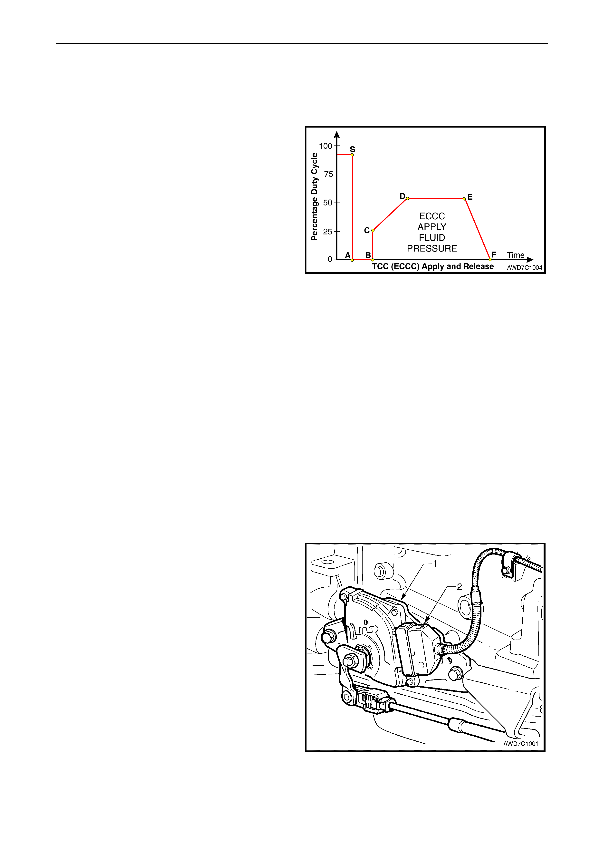
In first gear, at approximately 13 km/h, the PCM operates
the TCC PWM solenoid valve at approximately 90% duty
cycle (point 'S'). This duty cycle is maintained until a TCC
apply is commanded. When vehicle operating conditions are
appropriate to apply the TCC, the PCM immediately
decreases the duty cycle to 0% ('A') then, after a time (point
'B') increases it to approximately 25% ('C').
The PCM then ramps the duty cycle up to approximately
50% to achieve regulated apply pressure ('D'). W ith the
ECCC system, the pressure plate does not fully lock to the
torque converter, instead a consistent slip of approximately
20 rpm is regulated.
The rate at which the PCM increases the duty cycle controls
the TCC apply. Similarly, the PCM also ramps down the
TCC solenoid duty cycle to control TCC release ('E' to 'F'). Figure 7C1 – 4
Under some high torque or high vehicle speeds, the converter clutch is fully locked. For example, with the MY 2004 AWD
Wagon, the Full Lock position occurs at 121 km/h and Full Lock Release at 114 km/h.
NOTE
Duty cycles quoted are for an example only. The
actual duty cycles will vary, both with vehicle
application and vehicle operating conditions.
Transmission Shift Points
With the MY2004 AWD Wagon vehicle con figuration, the shift poin ts ha ve also been modified from those publishe d for
MY 2003 VY and V2 Series vehicle and are provided in Section 7C3 Mechanical/Hydraulic Diagnosis in the MY 2004
AWD Wagon Service Information.
Neutral Safety and Back-Up (NSBU) Lamp Sw itch
The Neutral Safety and Back-up Lamp Switch (1) has been
changed, with a new supplier for this component. This has
also resulted in a single, positive lock wiring harness
connector (2) being used.
As a further security measure a Connector Protection
Assurance (CPA) (not shown), is also used to prevent the
lock from becoming dislodged.
Figure 7C1 – 5
Automatic Transmissi on – General Information Page 7C1-6
Page 7C1-6
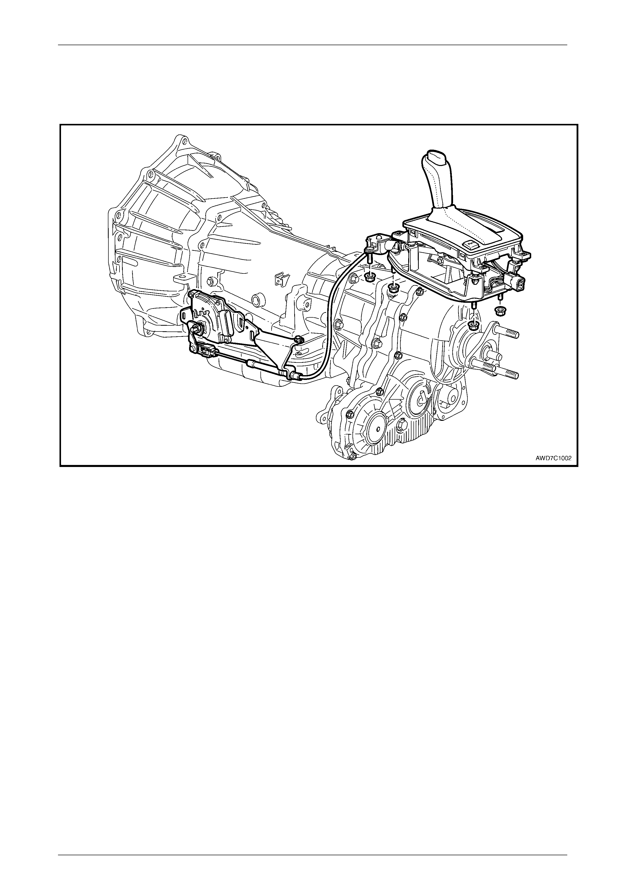
Shift Selector Mechanism
The transmission selector mechanism has been changed from linkage to cable operation, together with a re-designed
shift selector mechanism, refer to Figure 7C1-6.
Figure 7C1 – 6