
Automatic Transm issi on – Hydraulic/ Mechani cal Diagnosis Page 7C3-1
Page 7C3-1
Section 7C3
Hydra-matic 4L60 -E Automatic Transmission -
Hydraulic/Mechanical Diagnosis
ATTENTION
Before performing any Service Operation or other procedure described in this Section, refer to Section 00
Warnings, Cautions And Notes for correct workshop practices with regard to safety and/or property damage.
1 General Information............................................................................................................................... 2
2 MY2004 AWD Wagon – 4L60-E Shift Speed Charts............................................................................ 3
2.1 Introduction ............................................................................................................................................................3
2.2 Normal Mode Shift Pattern ....................................................................................................................................4
2.3 Power Mode Shift Pattern......................................................................................................................................5
2.4 Cruise Mode Shift Pattern......................................................................................................................................6
Techline

Automatic Transm issi on – Hydraulic/ Mechani cal Diagnosis Page 7C3-2
Page 7C3-2
1 General Information
Apart from the shift speed charts, the hydraulic and mechanical diagnosis for the Hydra-matic 4L60-E automatic
transmission fitted to MY2004 AWD Wagon models, carries over from MY 2003 VY and V2 Series vehicles. Therefore,
apart from the shift speed charts contained in this Section, refer to Section 7C3 Automatic Transmission
Hydraulic/Mechanical Diagnosis, in the MY 2003 VY and V2 Series Service Information, for all other hydraulic and
mechanical diagnosis.

Automatic Transm issi on – Hydraulic/ Mechani cal Diagnosis Page 7C3-3
Page 7C3-3
2 MY2004 AWD Wagon – 4L60-E
Shift Speed Charts
2.1 Introduction
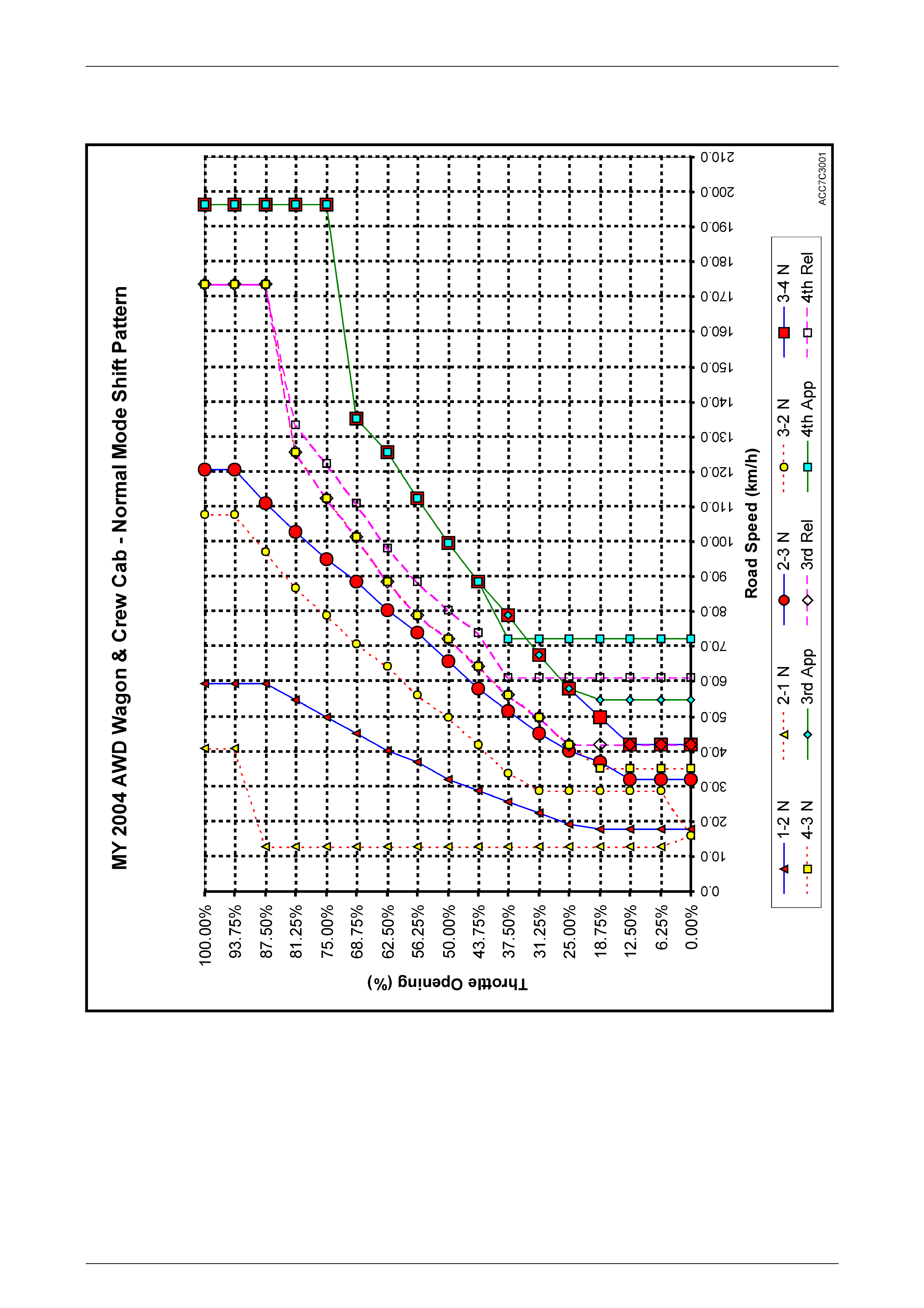
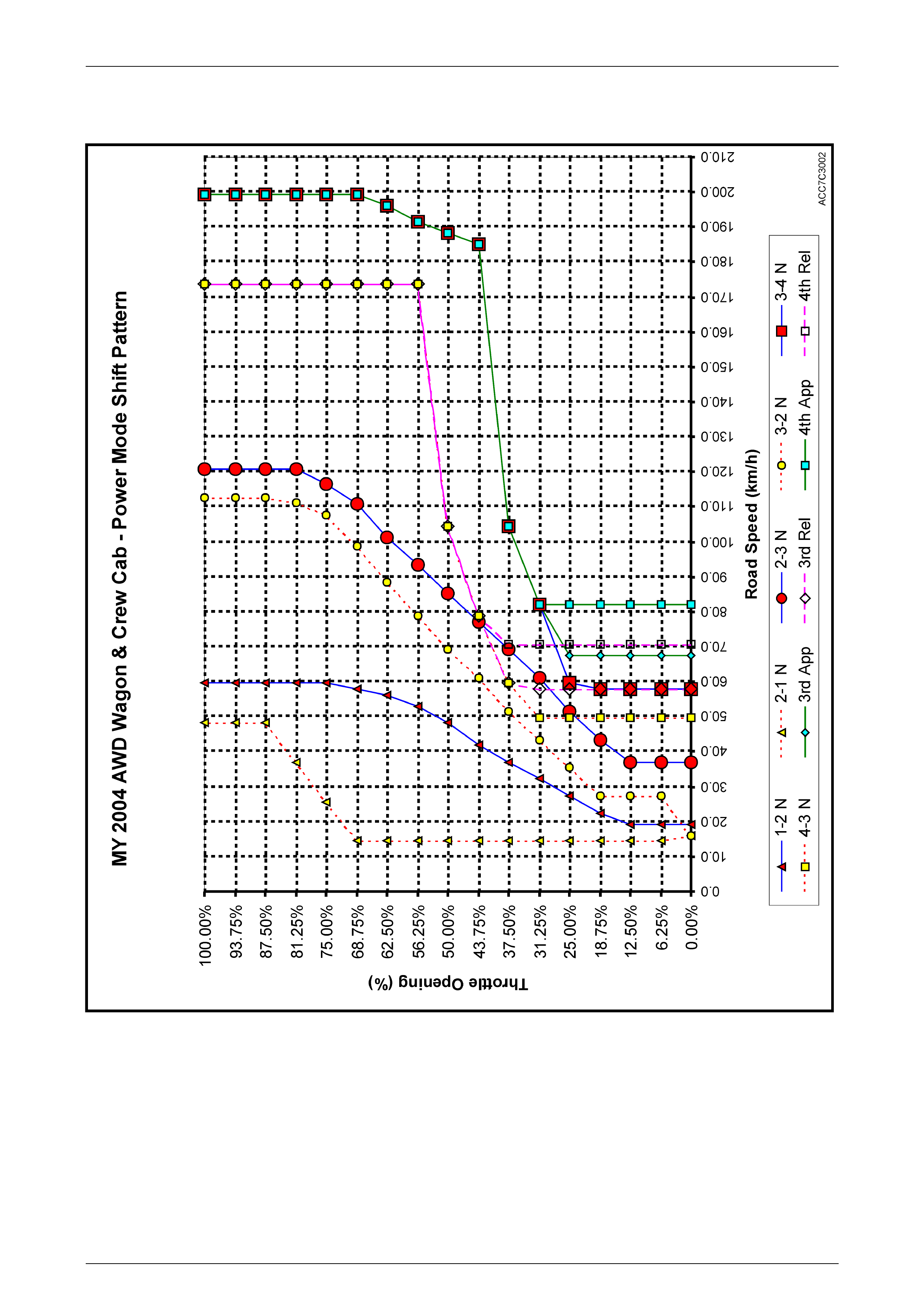
To assist in the interpretation of the following charts, the following criteria has been adopted:
1 All upshifts have a solid blue line and;
a 1-2 has red filled triangular plot points.
b 2-3 has red filled circular plot points.
c 3-4 has red filled square plot points.
2 All downshifts have a dashed red line and;
a 2-1 has yellow filled triangular plot points.
b 3-2 has yellow filled circular plot points.
c 4-3 has yellow filled square plot points.
3 Torque converter clutch apply points ('3rd App' and '4th App') have a solid green line and;
a '3rd App' has blue filled triangular plot points.
b '4th App' has blue filled square plot points.
4 Torque converter clutch release points ('3rd Rel' and '4th Rel') have a dashed pink line and;
a '3rd Rel' has white filled diamond plot points.
b '4th App' has white filled square plot points.
Automatic Transm issi on – Hydraulic/ Mechani cal Diagnosis Page 7C3-4
Page 7C3-4
2.2 Normal Mode S h ift Pattern
Figure 7C3-1
Automatic Transm issi on – Hydraulic/ Mechani cal Diagnosis Page 7C3-5
Page 7C3-5
2.3 Power Mode Shift Pattern
Figure 7C3-2

Automatic Transm issi on – Hydraulic/ Mechani cal Diagnosis Page 7C3-6
Page 7C3-6
2.4 Cruise Mode Shift Pattern
Figure 7C3-3