
Automatic Transmission – On-Vehicle Servicing Page 7C4-1
Page 7C4-17
Section 7C4
Hydra-matic 4L60 -E Automatic Transmission –
On-Vehicle Servicing
1 General Information............................................................................................................................... 2
2 Service Operations................................................................................................................................3
2.1 Shift Selector..........................................................................................................................................................3
Remove ...................................................................................................................................................................3
Disassemble ...........................................................................................................................................................5
Reassemble ............................................................................................................................................................6
Reinstall ..................................................................................................................................................................7
2.2 Shift Selector Cable ...............................................................................................................................................9
Remove ...................................................................................................................................................................9
Reinstall ................................................................................................................................................................10
Cable Adjust .........................................................................................................................................................11
2.3 Neutral Safety Back-Up Lamp Switch.................................................................................................................12
Remove .................................................................................................................................................................12
Reinstall ................................................................................................................................................................12
Adjust....................................................................................................................................................................13
Test........................................................................................................................................................................13
2.4 Automatic Transmission......................................................................................................................................15
Remove .................................................................................................................................................................15
Reinstall ................................................................................................................................................................15
3 Specifications....................................................................................................................................... 16
4 Torque Wrench Specifications........................................................................................................... 17

Automatic Transmission – On-Vehicle Servicing Page 7C4-2
Page 7C4-17
1 General Information
The Hydra-matic 4L60-E automatic transmission assembly fitted to MY 2004 AWD Wagon vehicles, carries over from the
transmission fitted to MY 2003 VY and V2 Series vehicles, except for;
• A re-designed shift selector.
• Cable controll ed shift lever control.
• A re-designed Neutral Safety Back-up Lamp switch.
• A changed length, transmission output shaft. However, once the adaptor housing/transfer case is removed, the
Unit Repair procedures are exactly the same as for MY 2003 VY and V2 Series vehicles.
For all service operations related to the transfer case adaptor housing, such as seals, speed sensor etc., refer to
Section 7F Transfer Case & Adaptor Housing, in the MY 2004 AWD Wagon Service Information.
Automatic Transmission – On-Vehicle Servicing Page 7C4-3
Page 7C4-17
2 Service Operations
LT Section No. – 04-190
2.1 Shift Selector
Remove
1 Remove floor console cover, lower extension side trim panels and the floor console assembly. Refer
Section 1A3 Instrument Panel and Console, in the MY 2003 VY and V2 Series Service Information.
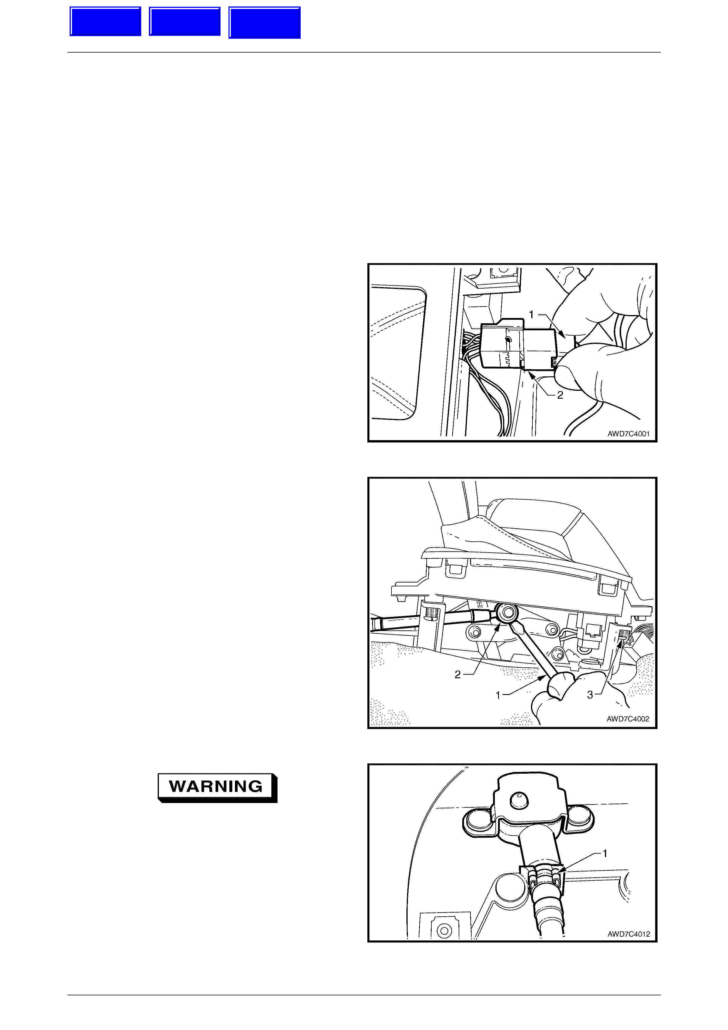
2 To disconnect the wiring harness connector (1) from
the selector patch harness (2), squeeze the locking
tang then pull the two wiring harness connector halves
apart.
Figure 7C4 – 1
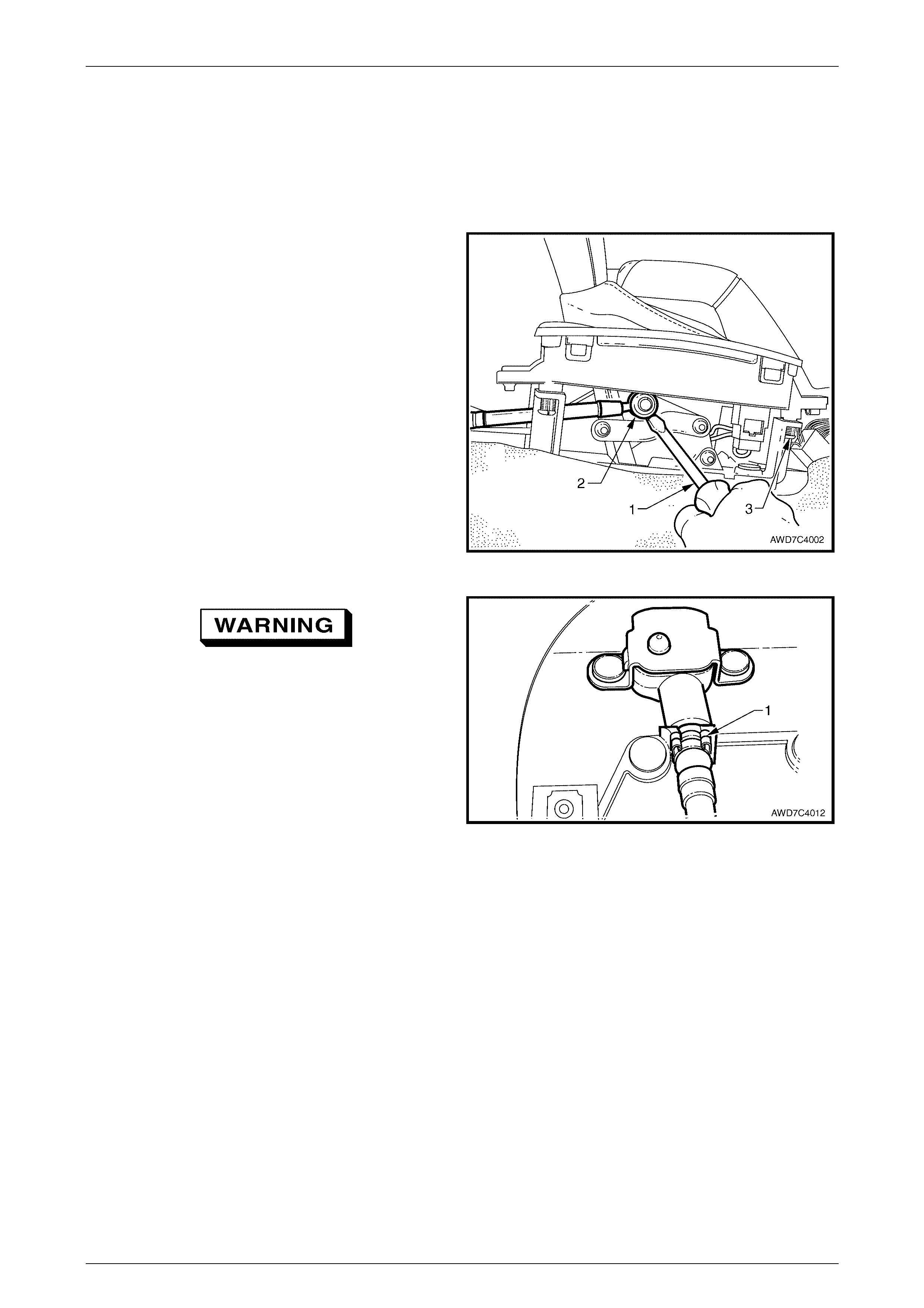
3 Using a small bladed screwdriver (1), prise the upper
end of the shift cable (2) from the shift selector lever
linkage pin.
NOTE
To gain clear access to the cable end, release
the two rear selector housing pegs (3) from the
base and lift up.
Figure 7C4 – 2
Wear eye protection to prevent injury.
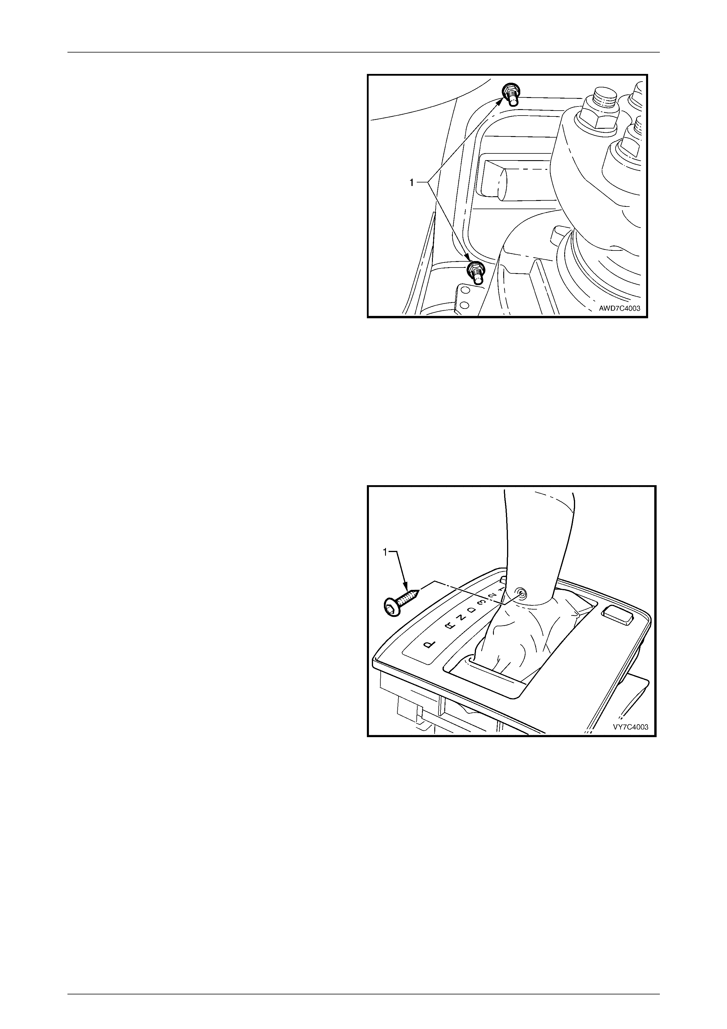
4 From inside the vehicle, use a screw driv er blade to
rotate the outer cable retaining clip (1) (if needed),
then remove the clip.
5 Raise vehicle and support in a safe manner. For
location of jacking and support points, refer to
Section 0A General Information, in this Service
Information.
Figure 7C4 – 3
Techline
Techline
Techline
Automatic Transmission – On-Vehicle Servicing Page 7C4-4
Page 7C4-17
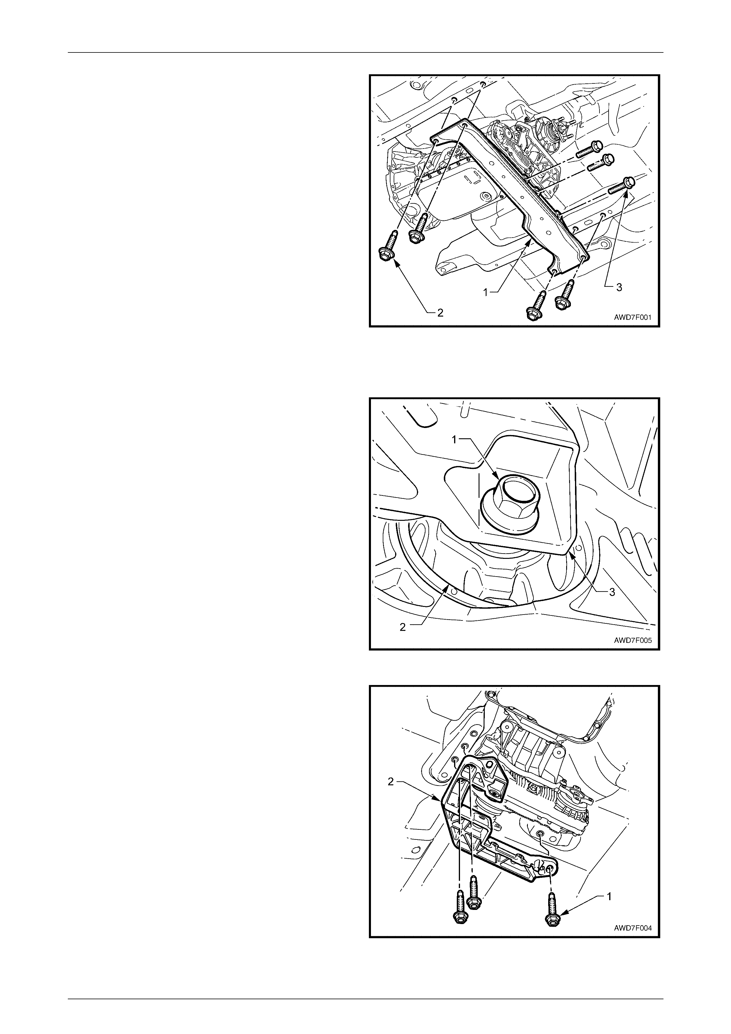
6 Using a felt tipped pen or similar (e.g. Whiteout
correction fluid), mark the position of the rear
crossmember (1) to the underbody side rails.
NOTE
This will assist in realigning the crossmember on
reinstallation.
7 Remove the four bolts (2) attaching the rear
crossmember (1) to the underbody side rails.
8 Remove the three bolts (3) securing the rear
crossmemb er to the transfer c ase mou nt brac ket (not
visible). Remove the crossmember from the vehicle.
NOTE
Support of the transmission is not required at
this time.
Figure 7C4 – 4
9 Remove the nuts securing the exhaust pipe bracket to each catalytic converter, then remove the two bolts securing
the bracket to the transfer case adaptor housing. Remove the bracket.
10 Using suitab le hydra uli c lifti ng equip me nt, supp ort the
transmissi on/transfer case und er the transfer case
housing.
11 With the automatic transmission/transfer case
supported, loosen the bolt (1) securing the transfer
case rubber mount (2) to the transfer case rear
mounting bracket (3).
Figure 7C4 – 5
12 Using a felt tipped pen or similar (e.g. Whiteout
correction fluid), mark the position of the transfer case
rear mounting bracket to the vehicle underbody.
NOTE
This will assist in realigning the mounting bracket
on reinstallation.
13 Loosen, then remove the three bolts (1) securing the
transfer case rear mounting bracket (2) to the vehicle
underbody.
14 Remove the loosened transfer case rubber mount to
transfer case rear mounting bracket bolt.
15 Remove the transfer case rear mounting bracket (2)
from the vehicle.
Figure 7C4 – 6
Automatic Transmission – On-Vehicle Servicing Page 7C4-5
Page 7C4-17
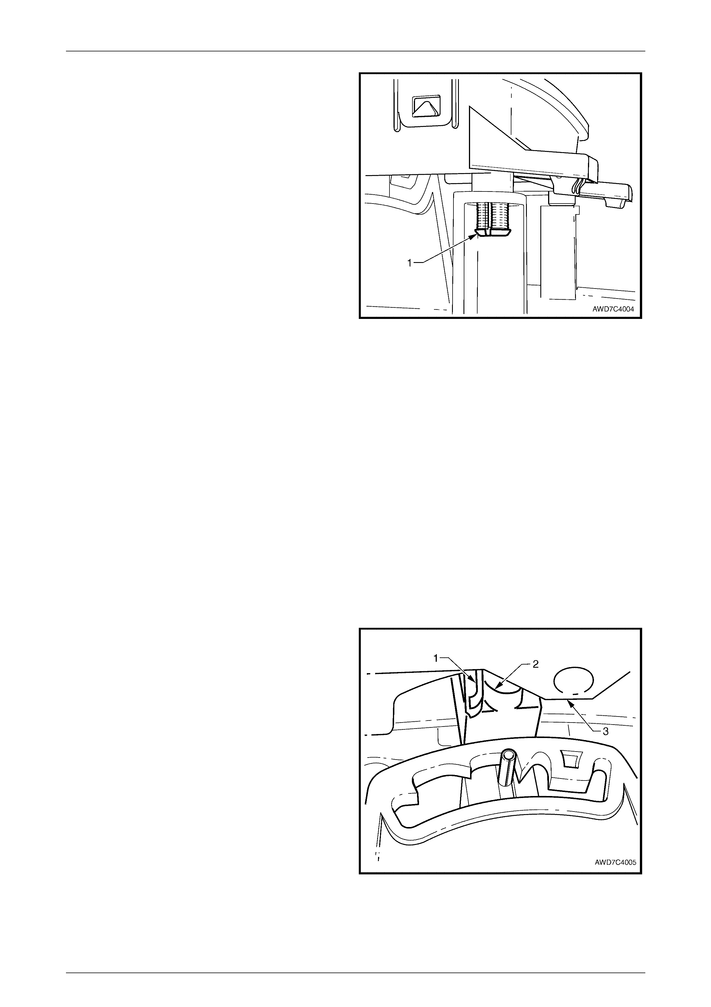
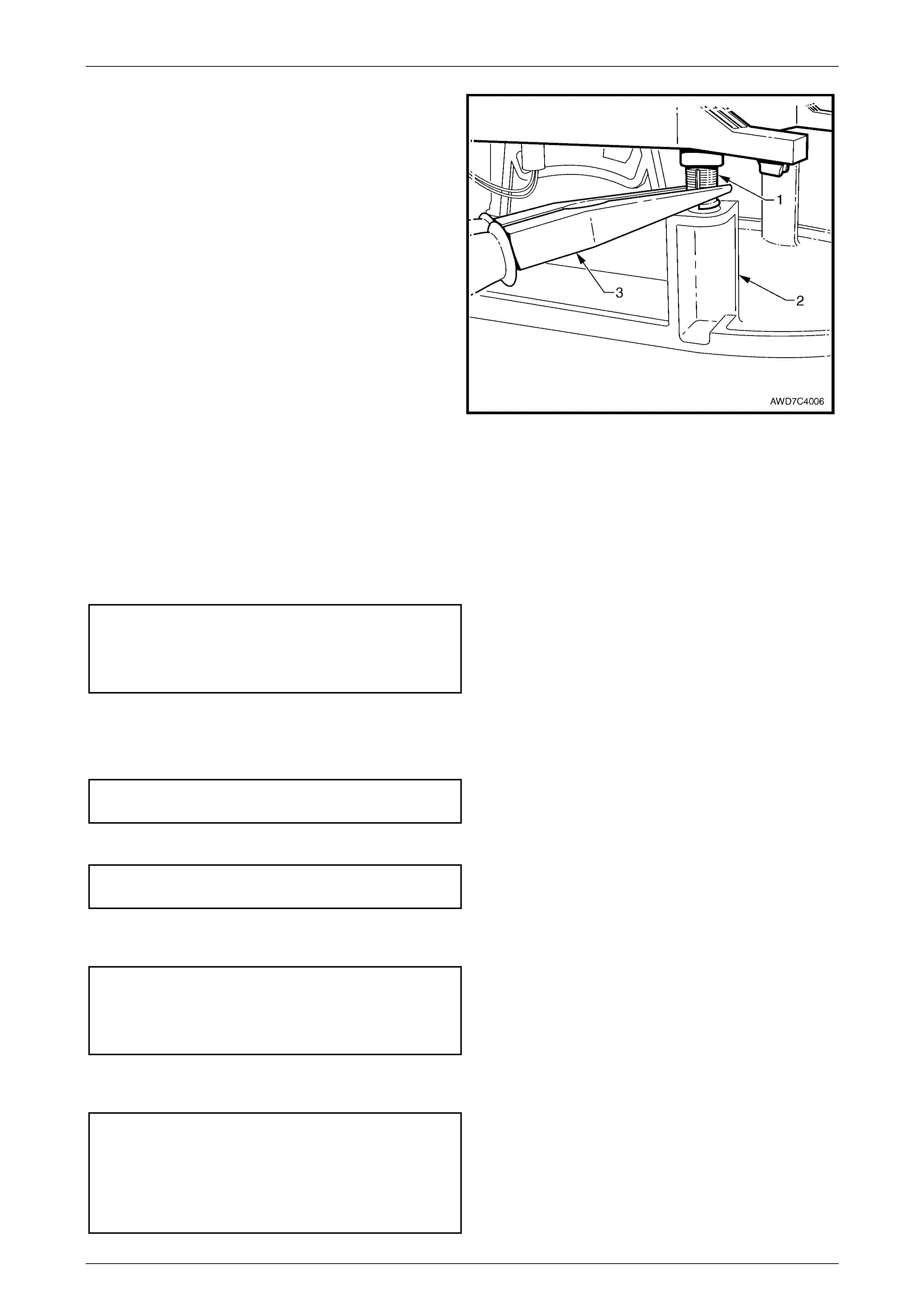
16 Lower the transmission/transfer case enough to gain
spanner access to the four nuts (1) securing the shift
selector assembly to the vehicle floor panel.
NOTE
Only two of the four nuts are visible in the view
shown.
17 Remove the four nuts securing the shift lever
assembly to the floor pan.
NOTE
To provide clearance to remove the shift
selector, it will also be necessary to remove the
two nuts securing the upper cable bracket and
grommet to the floor pan.
18 From inside the vehicle, lift the shift lever assembly
from the floor pan.
Figure 7C4 – 7
Disassemble
NOTE
Given that there are no serviceable items in the
shift lever nor the lower base, disassembly is
minimal and restricted to the lower housing and
associated components only.
1 Remove the Phillips headed self tapping screw (1).
Select ‘D’ Drive with the shift lever.
Figure 7C4 – 8
Automatic Transmission – On-Vehicle Servicing Page 7C4-6
Page 7C4-17
2 Use long nosed pliers to compress each of the lower
housing pegs (1), allowing the peg to be separated
from the base.
Figure 7C4 – 9
3 Lift the lower housing (1) from the base (2), together with the switch/es, patch wiring harness, boot and shift lever
knob. Set the assembly to one side.
4 For any of the following service operations on the lower and upper housing assemblies, refer to 3.3 Selector
Control Lever Assembly, Disassemble, Section 7C4 Automatic Transmission, in the MY 2003 VY and V2 Series
Service Information:
• Boot Replacement
• Gearshift Lever Knob Disassembly
• Cover Disassemble
• Patch Harness Replace
• Switch Replace
Reassemble
1 If any of the items mentioned in Step 4 of the Disassemble process are involved, refer to 3.3 Selector Control Lever
Assembly, Reassemble, Section 7C4 Automatic Transmission, in the MY 2003 VY and V2 Series Service
Information.
2 Position the selector lever (2) in the position shown,
then reinstall the lower housing assembly (3), over the
shift lever, engaging the shift lever pin and the shift
indicator lens connection (1), over the shift lever pin.
Figure 7C4 – 10
Automatic Transmission – On-Vehicle Servicing Page 7C4-7
Page 7C4-17
3 Engage each of the four pins (1) on the lower housing,
with the holes in the base (2), then engage each pin
with its respective hole, either by bumping with the
heel of the hand or use long nosed pliers (3) to
compress the pin and engage in the hole, as shown.
Figure 7C4 – 11
Reinstall
Reinstallation is the reverse to removal procedures except for the points noted;
1 Inspect the base insulator, replacing as required.
2 After reinstalling the shift selector assembly, reinstall the four retaining nuts and the upper cable bracket and
grommet nuts, tightening all to the correct torque specification.
Shift selector retaining nut
torque specific atio n ..............................................15 Nm
Shift cable bracket to floor pan
nut torque specification ........................................15 Nm
3 Reinstall the transfer case mount bracket, then reinstall the mount to bracket bolt. Do not tighten at this stage.
4 Raise the rear of the transfer case, realign the marks made before removal, then reinstall the three bracket
retaining bolts and tighten to the correct torque specification.
Transfer case mounting bracket
to underbody bolt torque specification..................58 Nm
5 Tighten the bracket to mount bolt to the correct torque specification.
Transfer case mount to bracket
bolt torque specification......................................100 Nm
6 Reinstall the rear crossmember, install the three crossmember to transfer case bracket bolts and the four
crossmember to underbody side rail bolts. Tighten all fasteners to the correct torque specification.
Rear crossmember to transfer
case bracket bolt torque specification ..................54 Nm
Rear crossmember to underbody
side rail bolt torque specification ..........................54 Nm
7 Reinstall the catalytic converter bracket, tightening the adaptor housing bolts and the catalytic converter to bracket
nuts to the correct torque specification.
Catalytic converter bracket to
adaptor housing bolt
torque specific atio n ..............................................25 Nm
Catalytic converter bracket to
catalytic conv ert er nut
torque specific atio n ..............................................25 Nm

Automatic Transmission – On-Vehicle Servicing Page 7C4-8
Page 7C4-17
8 Ensure that the rubber grommets at each end of the outer cable are fitted and in place. Failure to carry out this step
could result in the inner cable kinking the first time the shift lever is moved. This kinking condition will result in the
unnecessary replacement of the cable assembly.
9 Adjust the shift selector cable. Refer to 2.2 Shift Selector Cable, Cable Adjust in this Section.
10 Check the NSBU Lamp switch adjustment. Refer to 2.3 Neutral Safety and Back-up Lamp Switch, Adjust in this
Section.
Automatic Transmission – On-Vehicle Servicing Page 7C4-9
Page 7C4-17
2.2 Shift Selector Cable
Remove
1 Remove floor console cover, lower extension side trim panels and the floor console assembly. Refer
Section 1A3 Instrument Panel and Console, in the MY 2003 VY and V2 Series Service Information.
2 Using a small bladed screwdriver (1), prise the upper
end of the shift cable (2) from the shift selector lever
linkage pin.
NOTE
To gain clear access to the cable end, release
the two rear selector housing pegs (3) from the
base and lift up.
Figure 7C4 – 12
Wear eye protection to prevent injury.
3 From inside the vehicle, use a screw driv er blade to
rotate the outer cable retaining clip (1) (if needed),
then remove the clip.
Figure 7C4 – 13
4 Raise the vehicle, support in a safe manner and lower the rear of the transfer case to gain access to the upper
cable bracket to floor pan attaching nuts. Refer to Steps 4 – 14, in 2.1 Shift Selector, Remove, in this Section.
5 Use a set spanner to remove the two nuts securing the upper cable bracket and seal to the floor pan.
Automatic Transmission – On-Vehicle Servicing Page 7C4-10
Page 7C4-17
Wear eye protection to prevent injury.
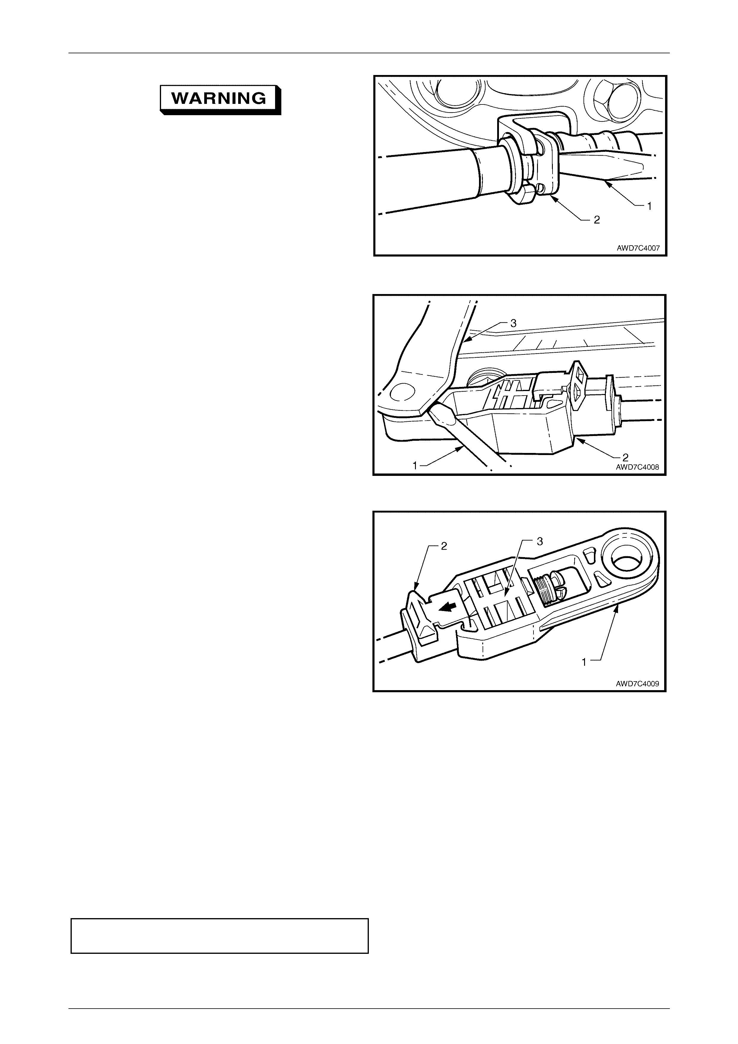
6 From under the vehicle, use a screwdriv er (1) to
release the cable to transmission bracket retaining clip
(2).
Figure 7C4 – 14
7 Use a small screwdriv er (1) to prise the shift cable end
(2) from the transmission external manual shaft lever
(3).
Figure 7C4 – 15
8 Slide the adjustment lock (2) back with the fingers,
then push the white, square, inner lock (3) out, using a
small screwdriver. Take care not to lose the inner lock
when released.
9 Dislodge the upper cable bracket and seal from the
floor pan and remove the cab l e asse mbly from insi de
the vehicle.
Figure 7C4 – 16
Reinstall
1 After checking that the upper cable bracket seal is in a serviceable condition, thread the shift selector cable
through the aperture in the floor pan, until the upper cable bracket studs can be installed through the floor pan
holes.
2 Install the upper end of the cable fitting to the shift selector linkage pin, by pushing inwards until the fitting is
install ed past the pin flan ge.
3 Engage the groove in the outer cable upper end with the slot in the shift selector base, then install a new retaining
clip to secure. Check that the outer cable rubber grommet is correctly fitted at the upper cable end.
4 Under the vehicle, reinstall the two cable bracket and seal to floor pan retaining nuts and tighten to the correct
torque specif ication.
Shift cable bracket to floor pan
nut torque specification ........................................15 Nm
Automatic Transmission – On-Vehicle Servicing Page 7C4-11
Page 7C4-17
5 After checking that the cable is routed correctly, raise the rear of the transfer case and reinstall the mount bracket
and rear crossmember to the vehicle underbody. Refer to Steps 3 to 7 inclusive, in 2.1 Shift Selector, Reinstall, in
this Section.
6 Reinstall the shift cable end to the transmission external manual shaft lever pin, checking that it is fully installed to
the pin. Leave the cable adjustment lock and white, square, inner lock in the released position, as the cable must
be adjusted after instal lati on.
Wear eye protection to prevent injury.
7 Under the vehicle, reinstall the outer cable clip, checking that it is fully engaged and in the correct position, forward
of the bracket that is bolted to the transmission case (refer to Figure 7C4-14). Check that the outer cable rubber
grommet is correctly fitted at the lowe r cable end.
Cable Adjust
1 Move the transmission external shift lever into the Park position, then ensure that the transmission selector lever is
also in the Park position.
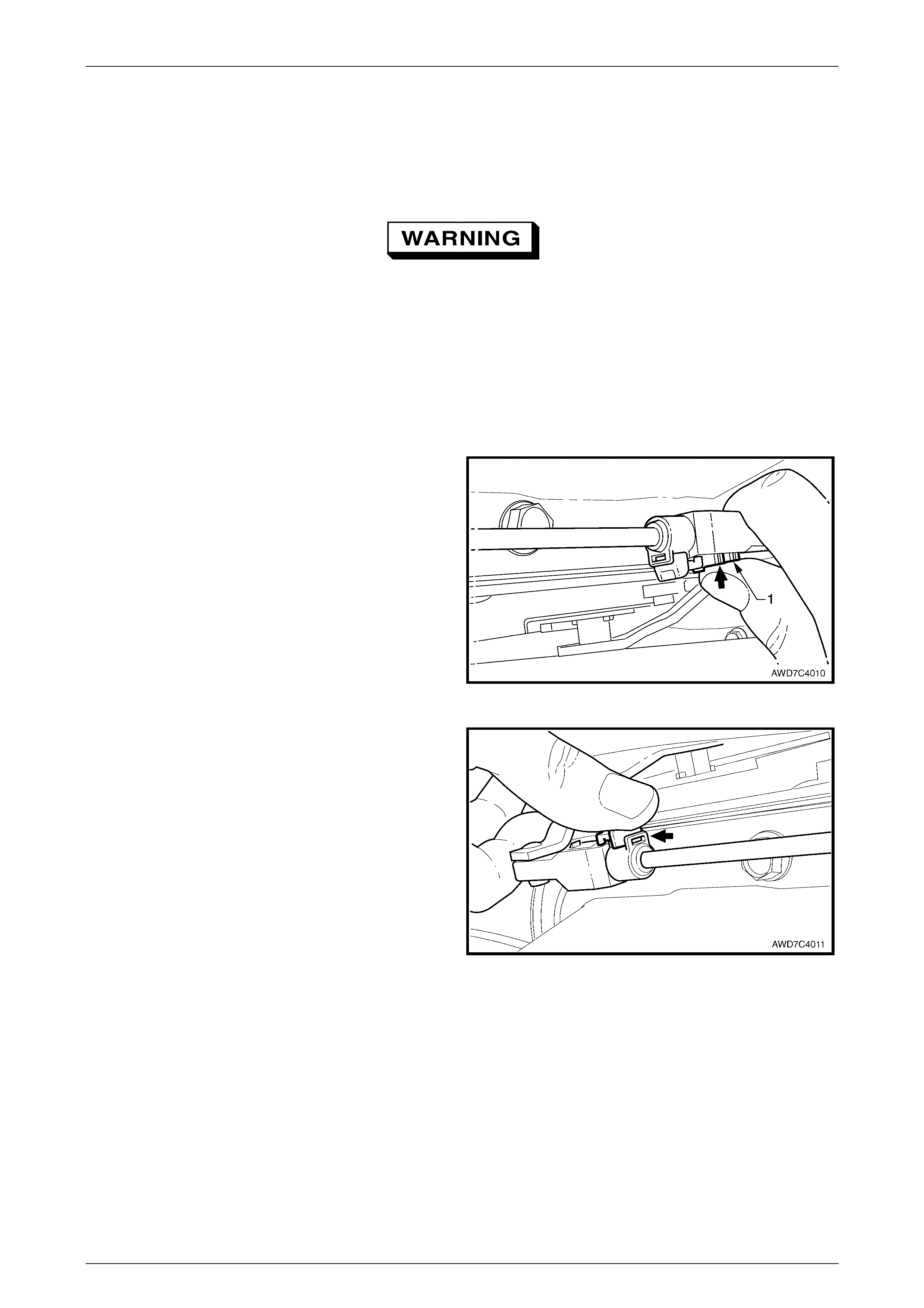
2 Push the white square inner lock (1) inward to engage
with the serrated cable end.
Figure 7C4 – 17
3 Secure the adjuster by sliding the adjustment lock
forward.
Figure 7C4 – 18
Automatic Transmission – On-Vehicle Servicing Page 7C4-12
Page 7C4-17
2.3 Neutral Safety Back-Up Lamp Switch
Remove
1 Select the 'Park' position.
2 Raise vehicle and support in a safe manner. Refer to Section 0A General Information, in this Service Information
for the location of jacking and support points.
3 Remove the front propeller shaft. Refer to Section 4C2 Front Propeller Shaft, Remove, in this Service Information.
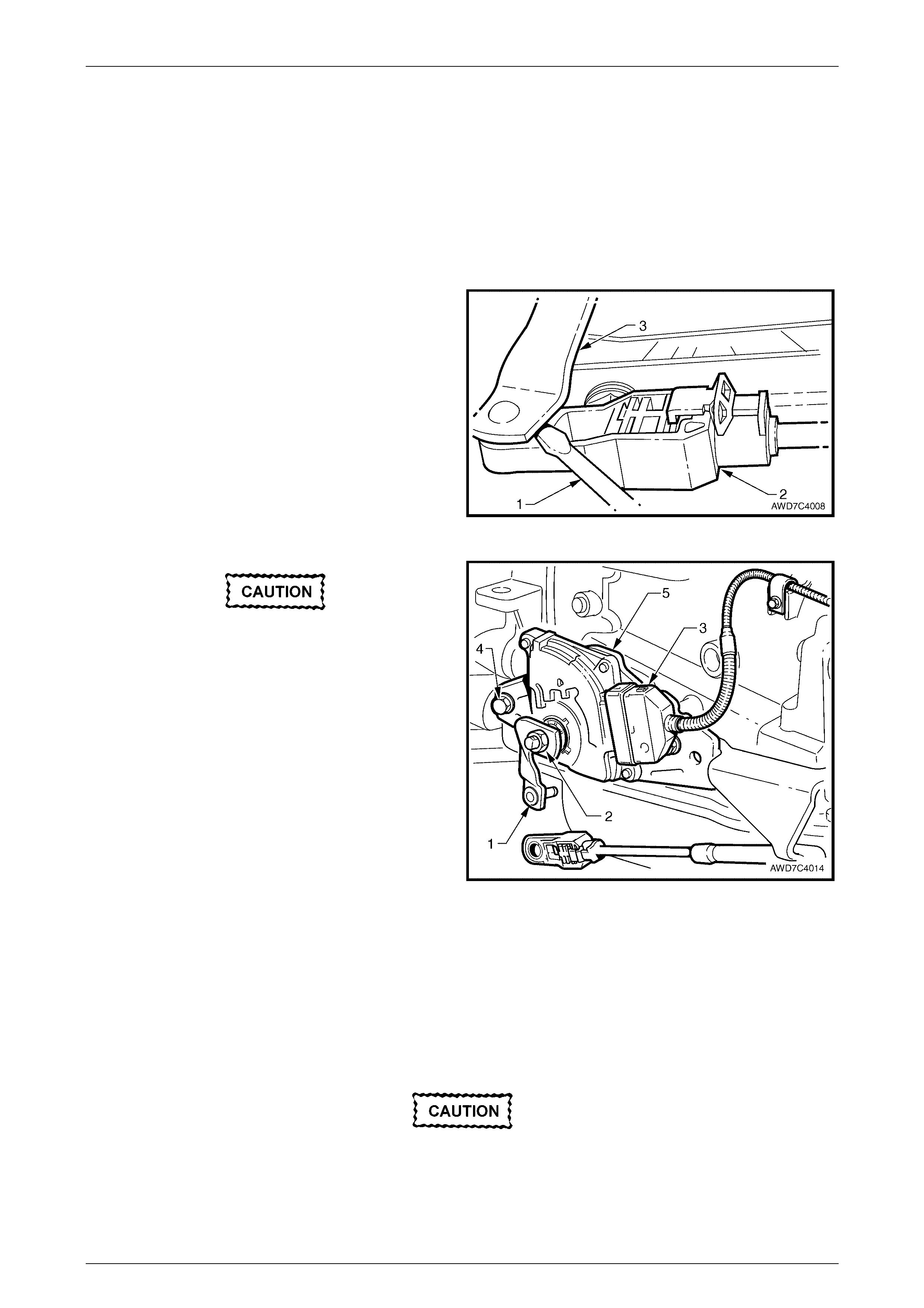
4 Using a small screwdriver blade (1) prise the selector
cable end (2) from the transmission external manual
shaft lever (3).
Figure 7C4 – 19
Under no circumstances is an impact gun to
be used to loosen the external transmission
selector lever retaining nut.
5 While holding the transmission external manual shaft
lever (1) with an adjustable wrench, loosen then
remove the lever attaching nut (2). Remove the lever
from the transmission selector shaft.
6 Remove the Connector Protection Assurance (CPA)
lock (not shown), then pull the wiring harness
connector security slide down. Remove the released
wiring harness connector (3) from the NSBU switch.
7 Remove both screws (4) securing the NSBU switch (5)
to the transmission case, then slide the switch over the
flats on the transmission selector shaft to remove the
switch from the transmission.
Figure 7 – 20
Reinstall
Reinstallation is the reverse to the removal procedure, except for the following:
1 After installation of the switch over the transmission selector shaft, secure the switch with the two retaining screws
but leave them finger tight.
2 Reinstall the transmission external manual shaft lever, indexing with the flats on the shaft.
Do not use an impact wrench to tighten the
external lever nut.

Automatic Transmission – On-Vehicle Servicing Page 7C4-13
Page 7C4-17
3 Install the nut securing the external manual shaft lever, then tighten to the correct torque specification, while
holding the lever with an adjustable wrench.
Transmission external manual shaft
lever nut torque specification................................15 Nm
4 Reinstall the wiring harness connector but do not install the CPA at this time, as the switch must be adjusted first.
5 Reinstall the shift selector cable fitting to the external manual shaft lever pin, then check the cable adjustment.
Refer to Cable Adjust in 2.2 Shift Selector Cable, in this Section.
6 Adjust the neutral start and back-up lamp switch position as described in the next procedure.
7 Reinstall the front propeller shaft, refer to Section 4C2 Propeller Shaft & Universal Joints, in the MY 2004 AWD
Wagon S ervice Information.
Adjust
1 With the vehicle still raised, rotate the neutral start and back-up lamp switch body, back and forth until a central
position is attained, then lightly tighten the front bolt to retain.
2 With the ignition switched to the ON position, check that the engine can only be started in both the Park and
Neutral selector positions. A further minor switch adjustment may be required to achieve this state.
3 Also check that the back-up lamps illuminat e when Rev erse range is sel ect ed.
4 After the switch adjustment, tighten the switch retaining screws to the correct torque specification.
NOTE
To gain access to the rear screw, it will be
necessary to remove the wiring harness
connector once again.
Neutral start and back-up
lamp switch retaining screw
torque specific atio n ..............................................25 Nm
5 Following the bolt tightening procedure, reinstall the wiring harness connector and engage the security slide and
the CPA lock.
6 Lower the vehicle to the ground and check the operation of the NSBU lamp switch. The vehicle should only start in
either ‘P’ (Park) or ‘N’ (Neutral) ranges and the Back-up lamps should only illuminate when the ‘R’ (Reverse) range
is selected.
Test
1 Check the shift selector cable adjustment. Refer to Cable Adjust, in 2.2 Shift Selector Cable, in this Section.
2 Check that the neutral start and back-up lamp switch is adjusted correctly. Refer to Adjust, in 2.3 Neutral Start and
Back-up Lamp Switch, in this Section.
3 With the ignition switch in the ON position and the instrument active, check that the display in the Multi Function
Display (MFD) in the instrument displays 'P' when the selector is in the Park position.
4 Move the shift selector lever through each of the range positions and check that the MFD shows that the selected
range is displayed .
5 Check that the engine will only crank when the Park and Neutral positions are selected.
6 Check that, when Reverse is selected, the back-up lamps are activated.
7 If any of the checks detailed in Steps 3 to 6 fails, refer to Instrument Panel Gear Indicator Check, in
Section 6C3-2C Functional Checks, in the MY 2003 VY and V2 Series Service Information.
Automatic Transmission – On-Vehicle Servicing Page 7C4-14
Page 7C4-17
Figure 7C4 – 21
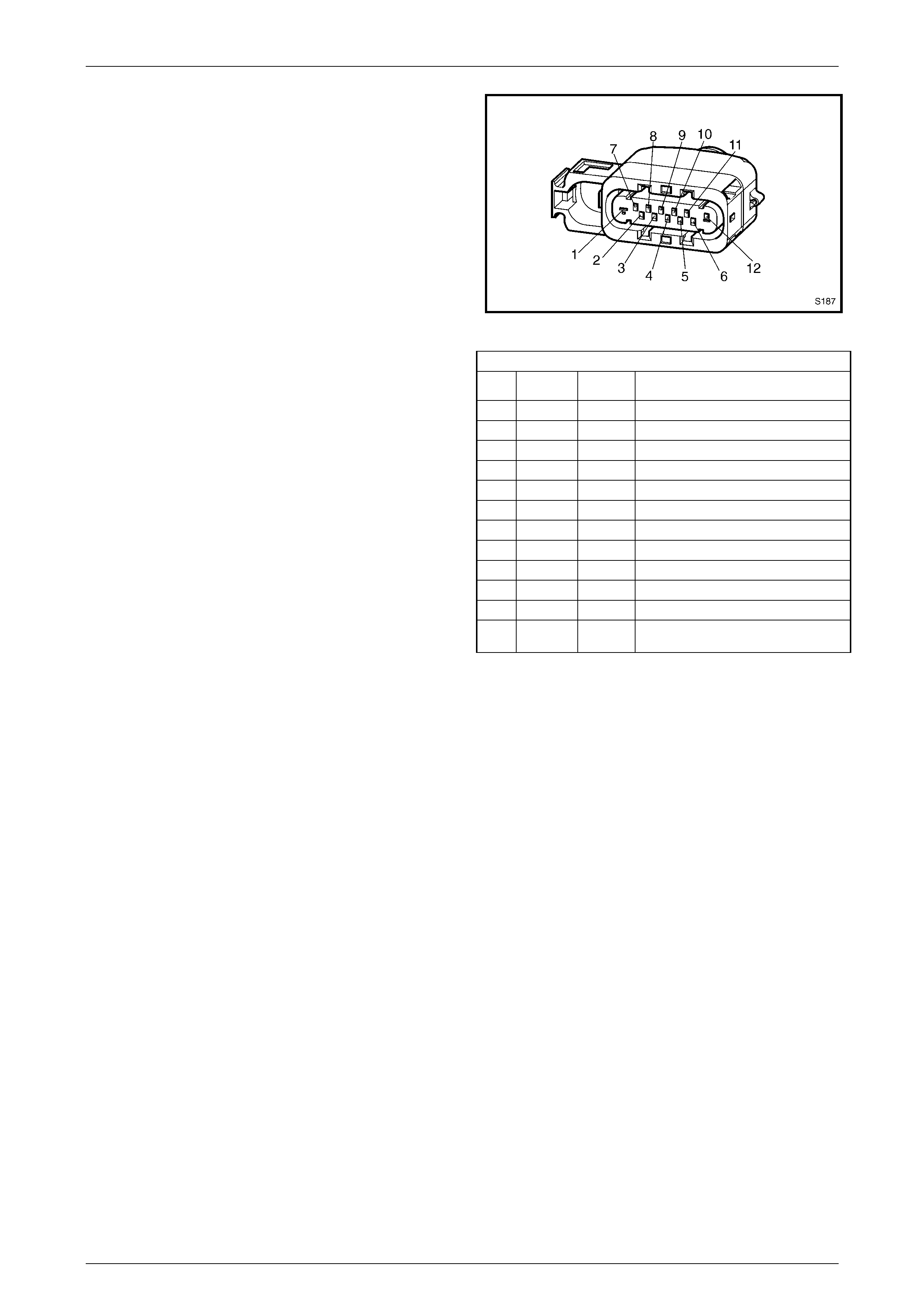
S187 – X1 NSBU Lamp Switch Connector
Pin Wire
Colour Circuit
No. Function
1 GY/BU 275 Start Relay R1 input to PIM
2 – – Not Used
3 – – Not Used
4 YE 772 PRNDL Switc h Input B
5 BU/WH 771 PRNDL Switc h Input A
6 GY 773 PRNDL Switch Input C
7 BK/RD 450 PRNDL Switch Ground
8 WH 776 PRNDL Switch Input P
9 – – Not Used
10 L-GN 24 Back-Up Lamps
11 BN/BU 239 B+ from Turn Signal Fuse F12
The pin number, wire colour and function for each circuit
connected to the Neutral Start and Back-Up Lamp switch
connector S187, as fitted to the MY 2004 AWD Wagon
Service Information, is as shown.
12 GY 434 B+ fro m Igni tio n Switch ' Sta r t '
Position

Automatic Transmission – On-Vehicle Servicing Page 7C4-15
Page 7C4-17
2.4 Automatic Transmission
Remove
Despite there being a transfer case and adaptor housing attached to the rear of the 4L60-E automatic transmission, the
'in-vehicle' removal procedures for the MY 2004 AWD Wagon, are the same as those detailed for the MY 2003 VY and
V2 Series range of vehicles, fitted with the GEN III V8 engine, except for removal of the front propeller shaft.
Therefore, refer to Section 4C2 Front Propeller Shaft, in this Service Information, and 3.14 Transmission Assembly,
Remove, in Section 7C4 Automatic Transmission – On-Vehicle Servicing, in the MY 2003 VY and V2 Series Service
Information.
Reinstall
Reinstallation of the 4L60-E automatic transmission, is the reverse of removal procedures except for transfer case and
front propeller shaft fasteners. Refer to 4 Torque Specifications in this Section for these torque specifications.

Automatic Transmission – On-Vehicle Servicing Page 7C4-16
Page 7C4-17
3 Specifications
NOTE
Only an abridged specification listing is provided
here. For all components not discussed in this
Section, refer to Section 7C5 Hydra-matic 4L60-E
Automatic Transmission – Unit Repair, in the MY
2003 VY and V2 Series Service Information.
General
Type..........................................................................................................Hydra-matic 4L60-E
Transmission Code........................................................................................................4HWD
Special Features................................... Electronically controlled shift pattern, feel and torque
converter clutch operation
Selector Location .................................................................................Floor mounted console
Gear Ratios
Park (P)............................................................................................................................... NA
Reverse (R).................................................................................................................. 2.294:1
Neutral (N) .......................................................................................................................... NA
Drive (D) ....................................................................................................................... 0 .696:1
Third (3) ....................................................................................................................... 1.000:1
Second (2) ................................................................................................................... 1.625:1
First (1)......................................................................................................................... 3.059:1
Shift Speeds
Refer to Shift Speed Charts, in...................Section 7C3 A/T Hydraulic/Mechanical Diagnosis,
in this Service Information.
Oil Pressure
Refer to 2.4 Line Pressure Check, in .........Section 7C3 A/T Hydraulic/Mechanical Diagnosis,
in the MY 2003 VY and V2 Series Service Information
Torque Converter
Number of Elements ..................................................................3 plus torque converter clutch
Maximum Torque Ratio at Stall.........................................GEN III V8 Engine - 2.15:1 (k=101)
Nominal Diameter ....................................................................................................... 300 mm
Lubricant
Type Recommended..............................................................................................Dexron III
Capacity (Nominal Only).....................Check when transmission is at operating temperature.
Refill............................................................................................................................5.0 litres
Total (Dry).................................................................................................................10.6 litres
Fluid Cooling...........................................Engine coolant to fluid in the left hand radiator tank.

Automatic Transmission – On-Vehicle Servicing Page 7C4-17
Page 7C4-17
4 Torque Wrench Specifications
ATTENTION
!
!!
! Fasteners must be replaced after loosening.
"
""
" Vehicle must be at curb height before final tightening.
#
##
# Fasteners either have micro encapsulated sealant applied or incorporate a mechanical thread lock and
should only be re-used once. If in doubt, replacement is recommended.
NOTE
Only an abridged torque wrench
specification listing is provided here. For all
components not discussed in this Section, refer
to Section 7C5 Hydra-matic 4L60-E Automatic
Transmission – Unit Repair, in the MY 2003 VY
and V2 Series Service Information.
Adaptor housing to transm is si on case bolt..............................................45 Nm
Catalytic converter bracket to adaptor housing bolt.................................25 Nm
Catalytic converter bracket to catalytic converter nut...............................25 Nm
Close-out cover securing screw – each side..............................................8 Nm
# Front propeller shaft constant velocity joint attaching bolt – All.............35 Nm
Intermediate exhaust pipe to catalytic converter flange bolt....................45 Nm
Neutral start and back-up lamp switch retaining screw............................25 Nm
Rear crossmember to transfer case bolt .................................................55 Nm
Rear crossmember to underbody side rail bolt ........................................55 Nm
# Rear propeller shaft centre bearing carrier to underbody bolt...............22 Nm
! Rear propeller shaft front coupling to transfer case flange nut..............78 Nm
# Rear propeller shaft rear CV joint to pinion flange bolt..........................35 Nm
Shift selector base retaining nut...............................................................25 Nm
Shift selector cable bracket to automatic transmission case bolt.............25 Nm
Shift selector cable bra cket to floor pan nut ............................................15 Nm
Speed sensor retaining screw..................................................................10 Nm
Starter motor attaching bolt......................................................................50 Nm
! Torque converter to engine flexplate attaching bolt ..............................65 Nm
Torque converter housing to engine block bolts (in sequence)................55 Nm
Transfer case to adaptor housing bolt......................................................45 Nm
Transfer case bracket to underbody bolt..................................................58 Nm
Transfer case mount to bracket bolt ......................................................100 Nm
Transmission external manual shaft lever nut..........................................15 Nm
Transmission filler tube bracket retaining bolt..........................................30 Nm
Transmission oil cooler pipe bracket bolt.................................................25 Nm
Transmission oil cooler pipe to power steering pipe bracket nut..............10 Nm
Transmission wiring harness bracket retaining screw..............................10 Nm