
Transfer Case & Adaptor Housing Page 7F – 1
Page 7F-1
Section 7F
Transfer Cas e & Adaptor Housing
ATTENTION
Before performing any Service Operation or other procedure described in this Section, refer to Section 00
Warnings, Cautions And Notes for correct workshop practices with regard to safety and/or property damage.
1 General Description............................................................................................................................... 3
1.1 General Information...............................................................................................................................................3
Arrangement...........................................................................................................................................................3
Power Flow .............................................................................................................................................................4
Vehicle Towing.......................................................................................................................................................4
1.2 Transfer Case Identification..................................................................................................................................5
1.3 Transfer Case Maintenance...................................................................................................................................6
Inspection ...............................................................................................................................................................6
Lubrication..............................................................................................................................................................6
Breather...................................................................................................................................................................6
2 Minor Service Operations .....................................................................................................................7
2.1 Checking Transfer Case Lubricant Level.............................................................................................................7
2.2 Draining/Filling Transfer Case Lubricant.............................................................................................................8
2.3 Transfer Case Front Output Flange, Slinger and Oil Seal...................................................................................9
Remove ...................................................................................................................................................................9
Reinstall ................................................................................................................................................................10
2.4 Transfer Case Rear Output Flange and Oil Seal................................................................................................12
Remove .................................................................................................................................................................12
Reinstall ................................................................................................................................................................13
2.5 Transfer Case Support Mount.............................................................................................................................15
Replace .................................................................................................................................................................15
3 Major Service Operations ................................................................................................................... 19
3.1 Transfer Case .......................................................................................................................................................19
Remove .................................................................................................................................................................19
Reinstall ................................................................................................................................................................22
3.2 Transfer Case, Input Shaft Oil Seal.....................................................................................................................24
Replace .................................................................................................................................................................24
3.3 Transmission Adaptor Housing..........................................................................................................................26
Remove .................................................................................................................................................................26
Reinstall ................................................................................................................................................................27
3.4 Transmission Adaptor Housing Oil Seal............................................................................................................28
Replace .................................................................................................................................................................28
4 Transfer Case Symptom Diagnosis................................................................................................... 29
4.1 Preliminary Diagnosis..........................................................................................................................................29
System Operation.................................................................................................................................................29
Visual/Physical Inspection..................................................................................................................................29
Symptom List........................................................................................................................................................29
4.2 Popping Noise......................................................................................................................................................30
4.3 Whine or Rumble Noise.......................................................................................................................................31
4.4 Growl or Grinding Noise......................................................................................................................................32
4.5 Clunk During Acceleration and Deceleration.....................................................................................................33
4.6 No Front or Rear Drive.........................................................................................................................................34
Techline
Techline
Techline
Techline

Transfer Case & Adaptor Housing Page 7F – 2
Page 7F-2
4.7 Lubricant Leak Diagnosis....................................................................................................................................35
5 Specifications....................................................................................................................................... 37
6 Torque Wrench Specifications........................................................................................................... 38
7 Special Tools........................................................................................................................................ 39
Transfer Case & Adaptor Housing Page 7F – 3
Page 7F-3
1 General Description
The New Process Gear model NV124 transfer case fitted to MY 2004 AWD Wagon models, is a single speed, full time,
All Wheel Drive (AWD) transfer case assembly, that provides one operating mode, 4HI full time AWD. The transfer case
uses a simple planetary gear train as a differential, to achieve a 38%/62% torque split between the front and rear final
drives. By utilising this gear set type, both final drives are constantly being driven for maximum traction and the best
balance or vehicle handli ng characteris tic s under all operating condit ion s.
An adaptor housing provides the means by which the transfer case is attached to the rear of the automatic transmission.
To cater for shaft length differences, an adaptor shaft is inserted between the transmission output shaft and the input
shaft of the transfer case. The vehicle speed sensor pick-up ring is an integral part of this adaptor shaft. The speed
sensor is mounted to the adaptor housing and is secured by a single screw as in normal practice.
The only serviceable components in the transfer case assembly, are those that do not require the housings to be split.
That is, the three oil seals, rear output flange, front output slinger, O-ring seals, filler and drain plugs, their gaskets and
the breather tube. The oil seal in the adaptor housing is a serviceable component but the adaptor shaft is only serviced
as a one-piece assembly. Service operations for the serviceable components are included in this Section.
1.1 General Information
Arrangement
Both transfer case housings are made from high pressure aluminium alloy, that contain the input, front and rear output
shafts, a simple planetary gear set and a connecting gear set. The internal gears are either supported by ball races, a
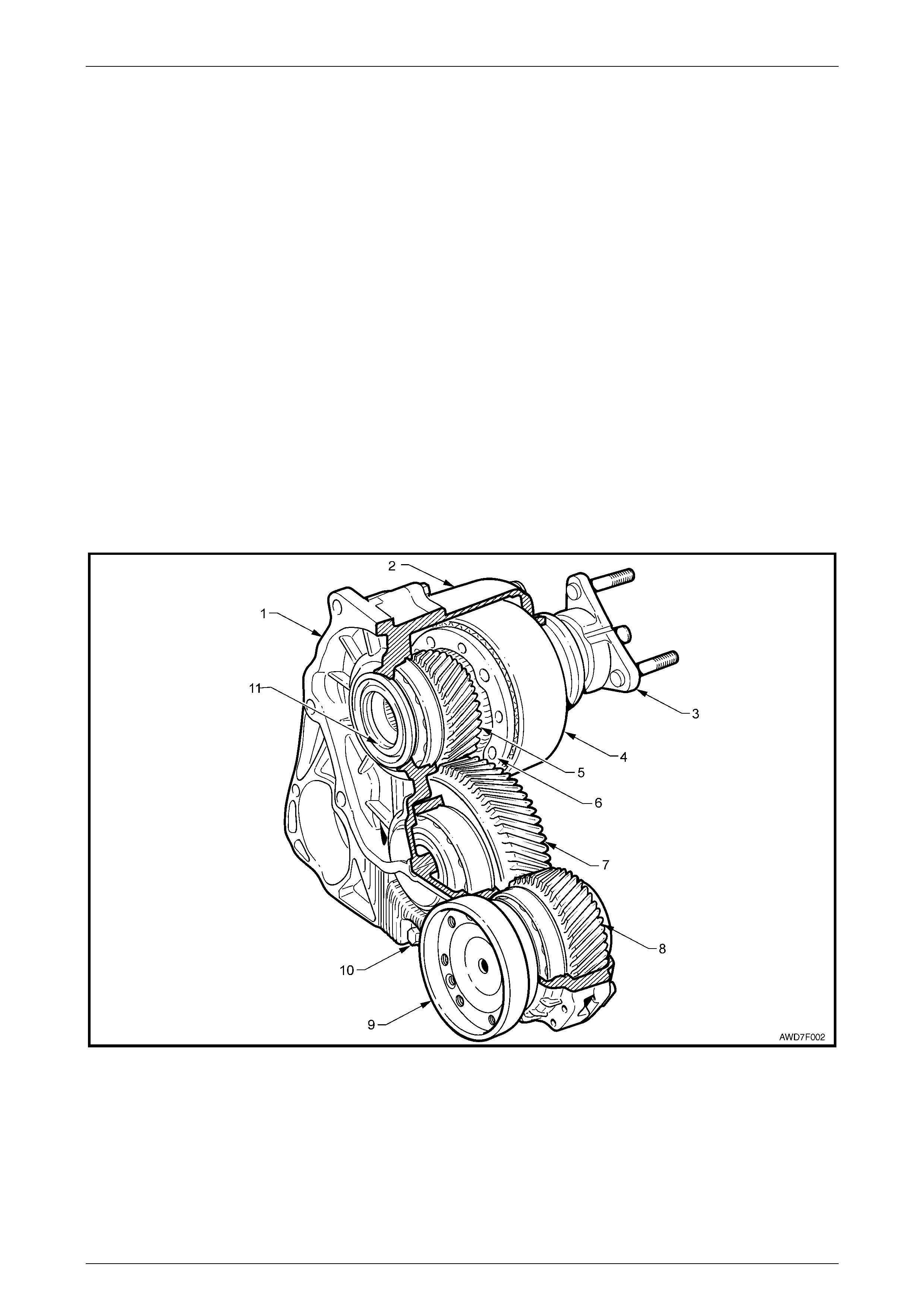
roller bearing or caged needle roller races. The organisation of the gears is as shown in the next sectioned view.
Figure 7F – 1
Legend
1 Transfer Case Front Housing and Internal O-Ring
2 Transfer Case Rear Housing
3 Rear Output Flange
4 Planetary Gear Set Ring Gear (Annulus)
5 Sun Gear
6 Planetary Gear Set Carrier & Pinions
7 Idler Gear
8 Front Output Gear
9 Front Output Flange
10 Drain Plug
11 Input Shaft
Transfer Case & Adaptor Housing Page 7F – 4
Page 7F-4
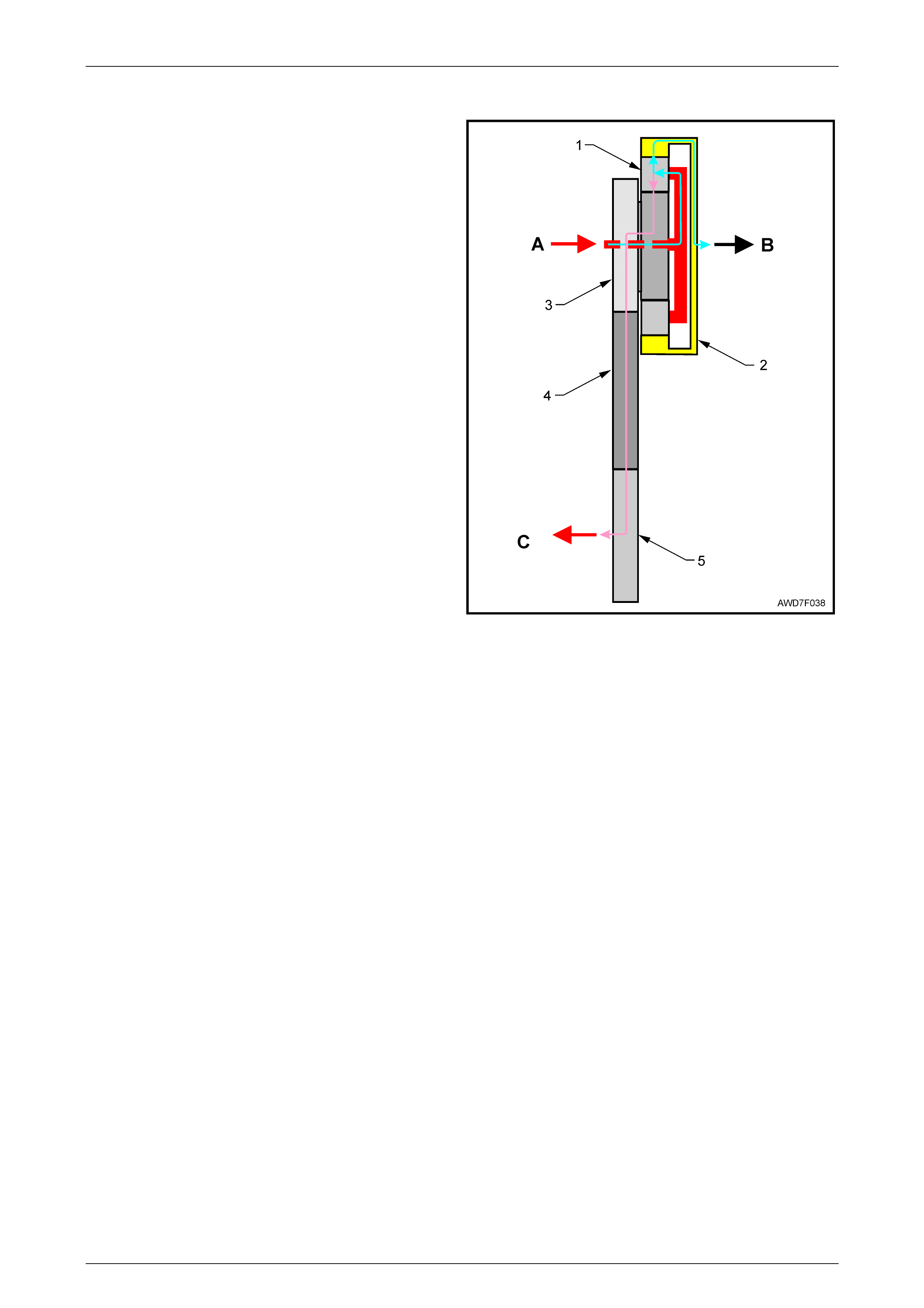
Power Flow
Power from the input shaft (A) flows to the planetary pinions
and carrier (1), then out to the rear final drive (B) via the ring
gear (2). Power also flows to the front final drive (C), via the
sun gear (3), idler gear (4) and front output gear (5).
With any simple planetary gear set, ratio change can be
achieved by one member being the input (driver), another
being the output (driven) and the third being held. If any two
members are held, the gear set is locked up or, if one or
more members is/are free, then Neutral is achieved.
With the MY 2004 AWD Wagon arrangement, the torque
split from the planetary gear set is 38/62, front to rear.
Should slip occur from either a front or rear wheel, then a
neutral situation occurs until traction control restores grip.
Figure 7F – 2
Vehicle Towing
Before towing this vehicle, all the recommendations stated in the MY 2004 AWD Wagon Owner's Handbook, in "Chapter
10 Tow and Load" and in particular, "10.5 Towing Your Vehicle", must be complied with.
In addition, it must be realised that, as the automatic transmission does not have a rear pump, extensive transmission/
transfer case damage will occur if the vehicle is towed at speeds in excess of 55 km/h or distances of more than 55 km.
Should it be considered prudent to remove a propeller shaft before towing on all four wheels, then both propeller shafts
must be removed. Given the constraints just mentioned, it is strongly recommended that towing on all four wheels be
avoided where possible and that flat top truck transport is recommended, particularly for long distances.
Transfer Case & Adaptor Housing Page 7F – 5
Page 7F-5
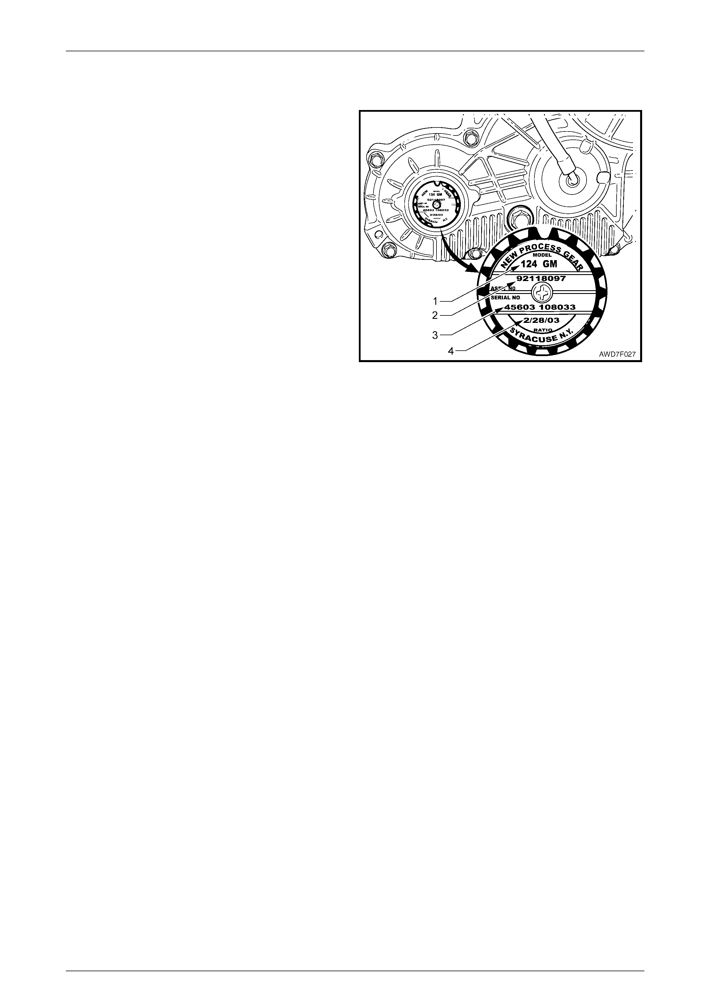
1.2 Transfer Case Identification
An identification tag is attached to the rear transfer case
housing, in the location shown. The information contained,
provides the transfer case serial number, build date and
other information that may be required for the correct
procurement of service parts.
If the tag is removed or is dislodged during service
operations, the tag must be kept with the assembly.
Legend
1 Model Number ('124')
2 Assembly Part Number
3 Serial Number
4 Build Date
Figure 7F – 3
Transfer Case & Adaptor Housing Page 7F – 6
Page 7F-6
1.3 Transfer Case Maintenance
Inspection
A check for lubricant leaks should be made at each maintenance service. If there is evidence of leakage, the condition
must be corrected using procedures contained in this Section, then drain the lubricant remainder and refill the transfer
case with the approved lubricant. Refer to 2.2 Draining/Filling Transfer Case Lubricant, in this Section.
Lubrication
For the transfer case lubricant draining frequency, refer to the MY 2004 AW D Wagon Owner's Handbook.
Should it be necessary to drain the lubricant and refill because of loss through a leaking seal, then it is vital that only the
recommended lubricant be used.
The only lubricant approved for use in this transfer case is Esso MTF-LT-1.
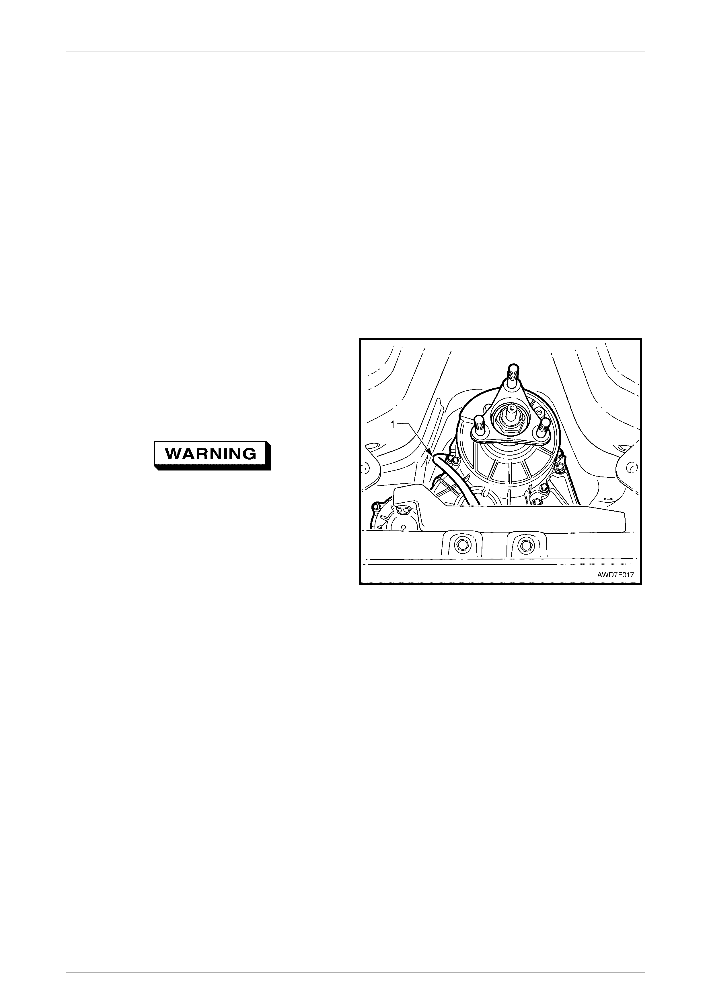
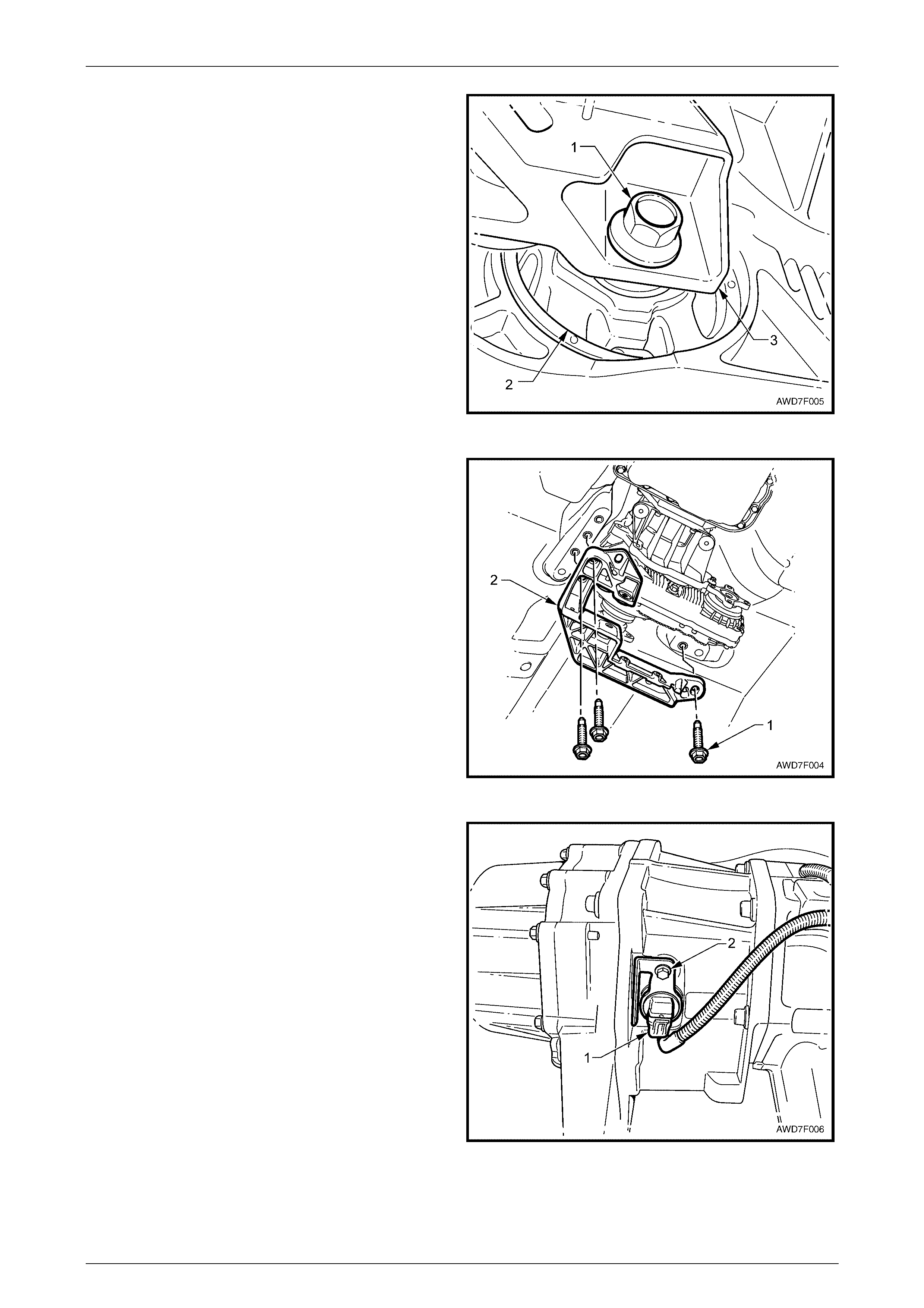
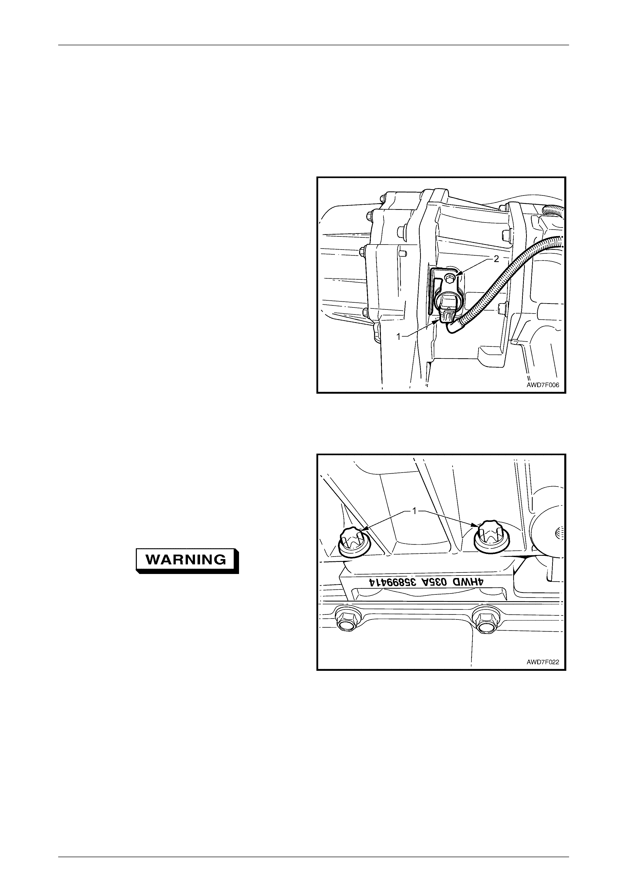
Breather
The breather hose (1) should also be inspected at each
maintenance service, to ensure that the hose is routed
correctly and is in good condition.
A check should also be made to ensure that the open end is
not blocked. This can be achieved by disconnecting the
hose from the breather pipe at the transfer case.
Wear eye protection when clearing a blocked
hose.
Then, either manually blow through the hose or use
compressed air. Reinstall the hose to the transfer case pipe.
Figure 7F – 4
Transfer Case & Adaptor Housing Page 7F – 7
Page 7F-7
2 Minor Service Operations
2.1 Checking Transfer Case Lubricant Level
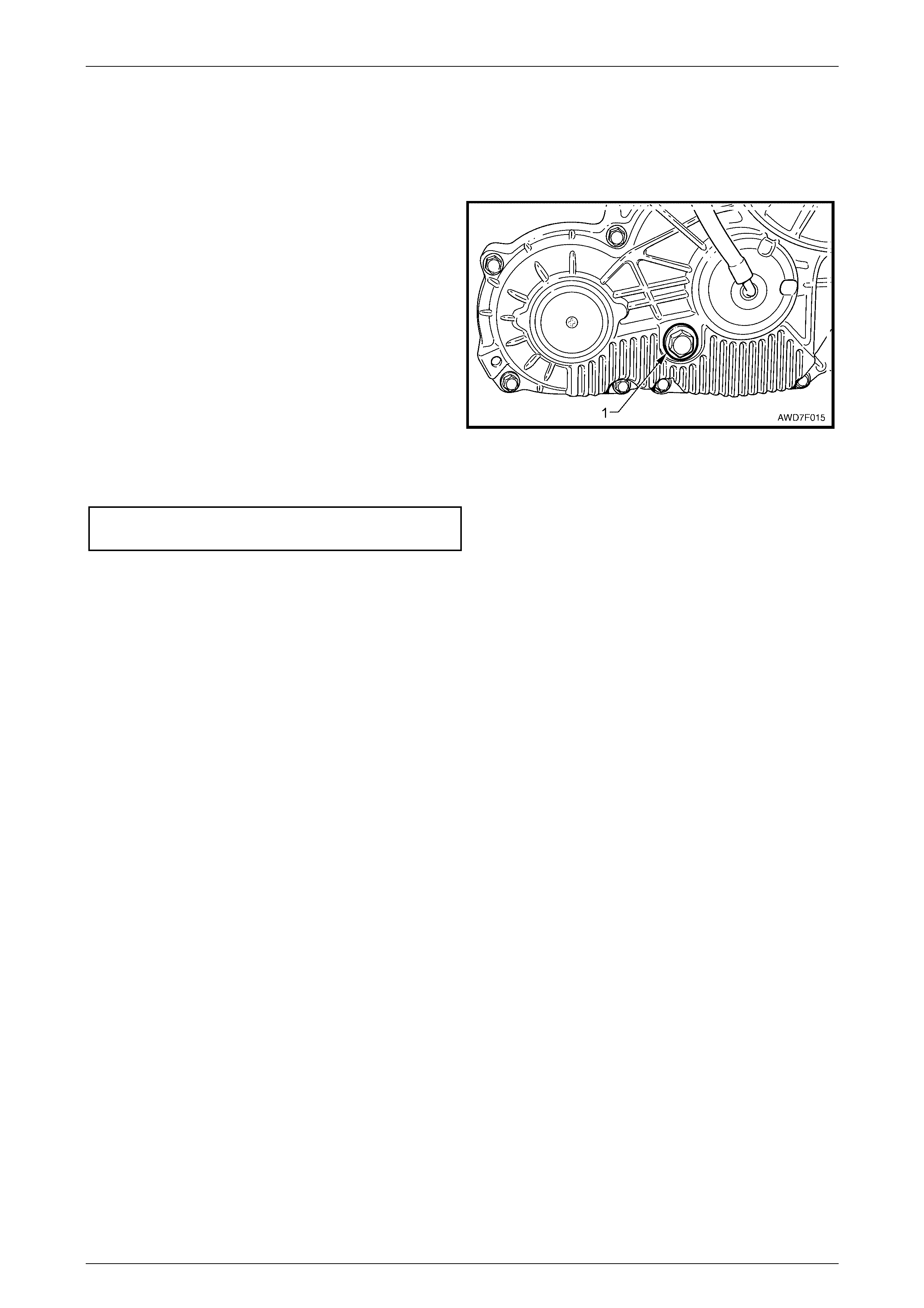
1 Ensure that the vehicle is level.
2 Clean the area around the filler plug (1).
NOTE
The view shows the transfer case mount bracket
and rear crossmember removed, to more clearly
show the filler plug location.
3 Remove the filler plug and gasket using a suitable size
ring spanner.
4 The level is correct when the lubricant
j
ust reaches the
filler plug threads in the rear transfer case housing,
when COLD.
5 Replace the filler plug gasket, then reinstall the filler
plug, tightening to the correct torque specification.
Figure 7F – 5
Transfer case filler plug
torque specific atio n ..............................................32 Nm
6 Should the lubricant level be found to be low, then the reason must be investigated and corrected.
7 After correction of the leakage condition, drain and refill the transfer case. Refer to 2.2 Draining/Filling Transfer
Case Lubricant, in this Section.
Transfer Case & Adaptor Housing Page 7F – 8
Page 7F-8
2.2 Draining/Filling Transfer Case Lubricant
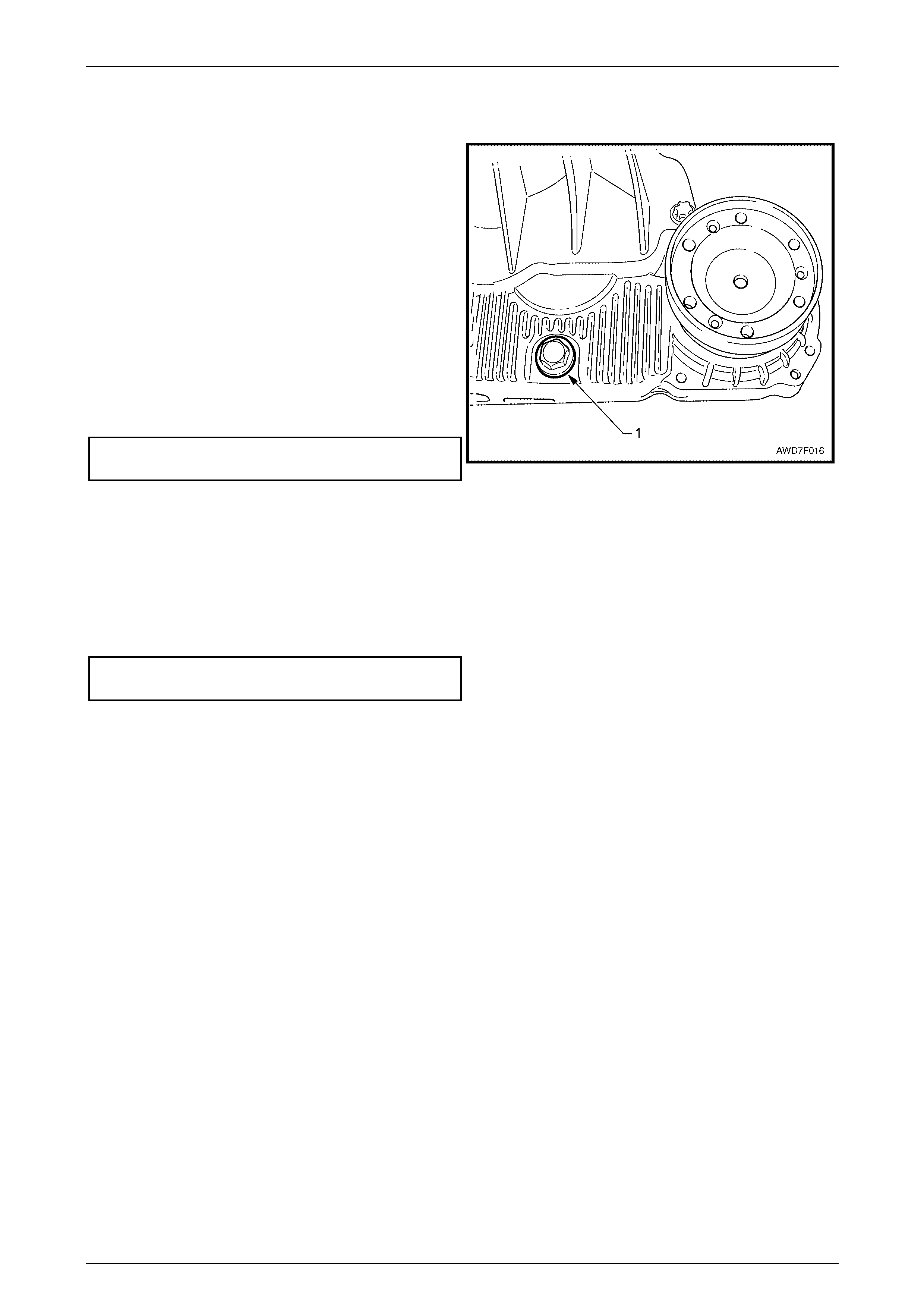
1 Clean the area around the drain plug (1) and filler plug
(refer to Figure 7F – 5).
2 Remove the filler plug, using a suitable size ring
spanner. Refer to Figure 7F-5 for the location.
NOTE
The view shows the catalytic converter bracket
and front propeller shaft removed to more clearly
show the drain plug location.
3 Remove the drain plug using a suitable size ring
spanner, draining the lubr ica nt into a suitable
container of a minimum 0.5 litre capacity.
4 Replace the drain plug gasket, then reinstall the plug,
tightening to the corr ect torque specification.
Transfer case drain plug
torque specific atio n ..............................................32 Nm
Figure 7F – 6
5 Refill the transfer case, with approximately 150 ml of Esso MTF-LT-1 lubricant.
NOTE
This is the approximate refill quantity. The 'dry' fill
quantity is 240 ml.
6 Replace the filler plug gasket, then reinstall the plug, tightening to the correct torque specification.
Transfer case filler plug
torque specific atio n ..............................................32 Nm
7 Check the lubricant level, adjusting as required. Refer to 2.1 Check ing Tr an sfer Case Lubricant Lev el, in this
Section.
Transfer Case & Adaptor Housing Page 7F – 9
Page 7F-9
2.3 Transfer Case Front Output Flange,
Slinger and Oil Seal
LT Section No: 04-050
Remove
1 Remove the front propeller shaft from the vehicle. Refer to 2.1 Propeller Shaft, Remove, in
Section 4C2 Front Propeller Shaft & Universal Joints, in this Service Information.
2 Place a drip tray under the transfer case.
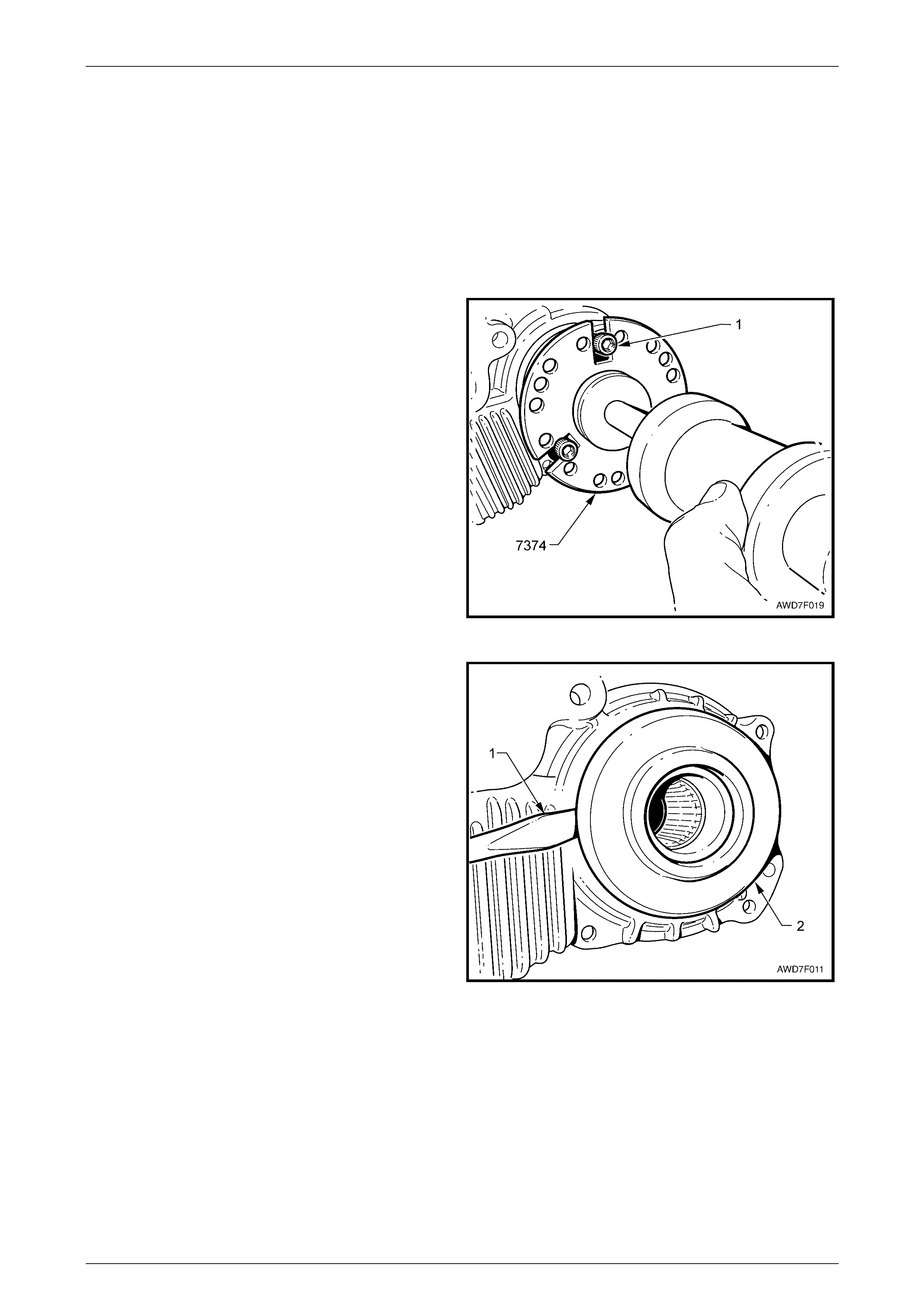
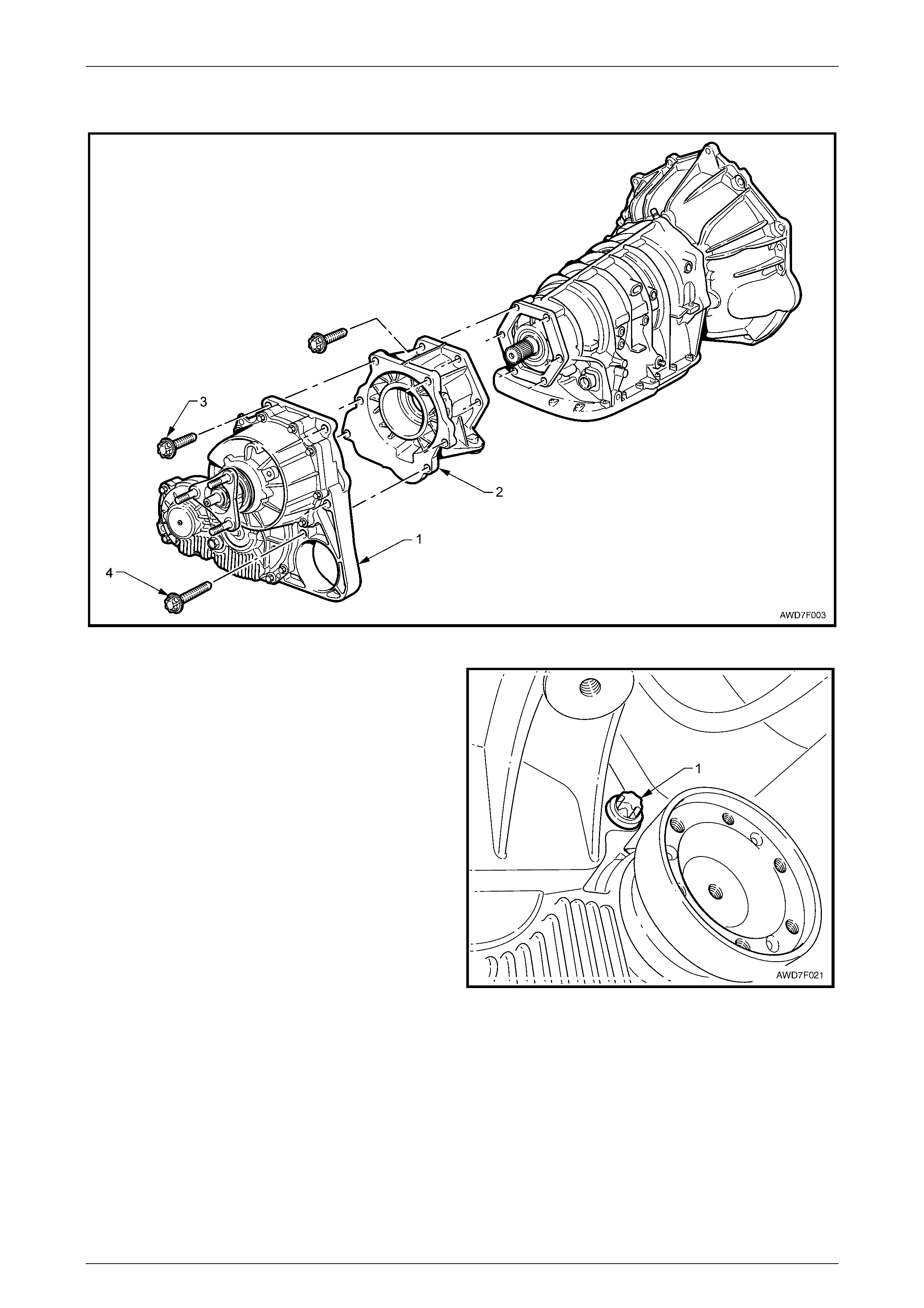
3 Using three suitable leng th 8 mm set screws (1),
attach slide hammer, Tool No. 7374 to the transfer
case front output flange.
4 Use the slide hammer to dislodge the flange snap ring
from the transfer case, front output shaft, then remove
the flange. Remove the slide hammer from the flange.
Figure 7F – 7
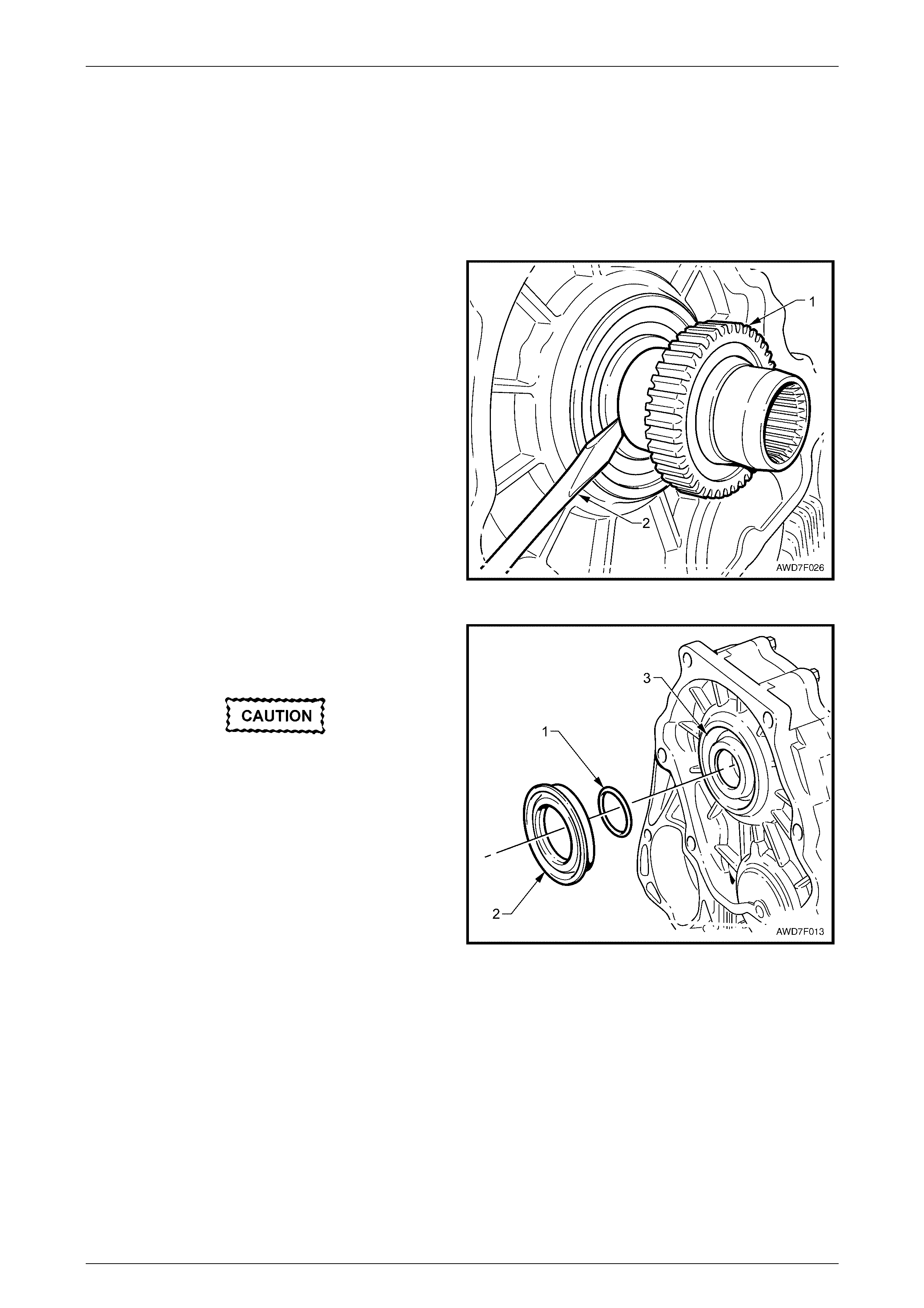
5 Use a screwdriver (1) or similar lever to prise the
slinger (2) from the transfer case front output shaft.
Discard the removed slinger as it will have been
distorted during the removal operation.
Figure 7F – 8
Transfer Case & Adaptor Housing Page 7F – 10
Page 7F-10
Be careful during the seal removal operation,
that damage to the transfer case machined
surfaces does not occur.
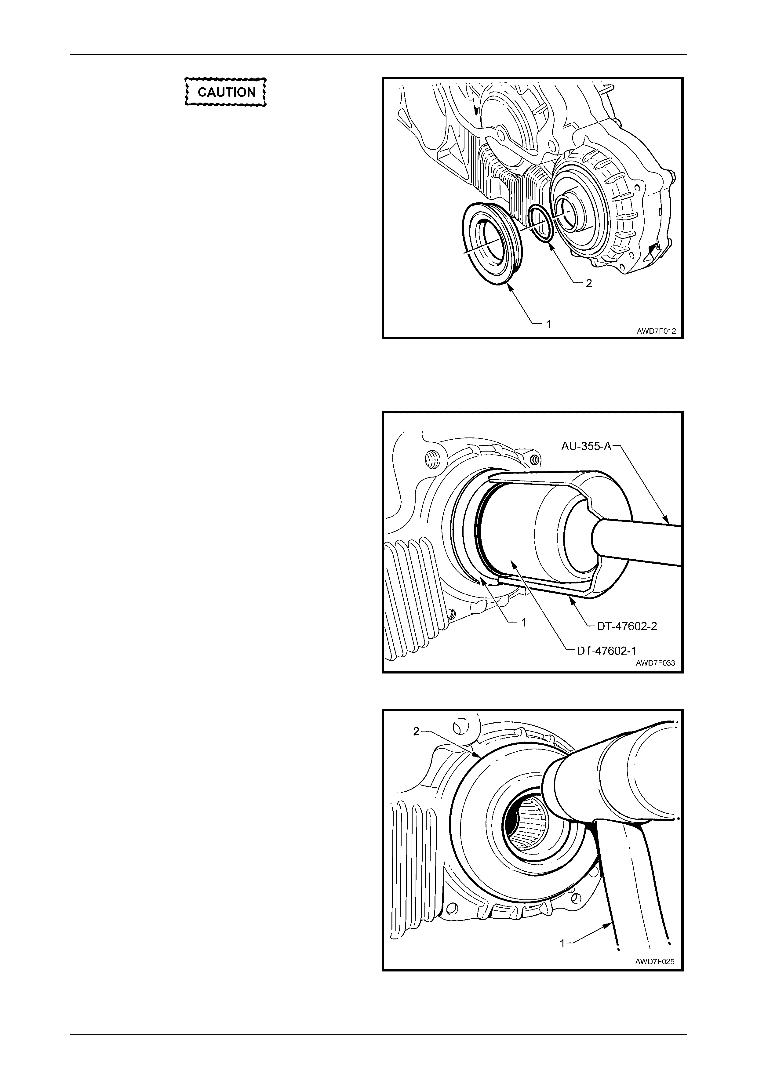
6 Remove the transfer case oil seal (1), using a cold
chisel and hammer, w orking ar ound t he outer sea l
perimeter. Discard the removed seal.
7 Use a small screwdriver or wire hook to remove the O-
ring seal (2) from the inside of the front output shaft.
Discard the removed O-ring.
Figure 7F – 9
Reinstall
1 Install the seal protector DT-47602-1 over the transfer
case, front output shaft and push to fully install.
2 Lubricate a new oil seal (1) with Mobilgrease XHP
222, ensuring that the recesses between the seal lips
are filled to approximately 50%, then slide the seal
over the protector.
3 Install driver, Tool No. AU-355-A into seal installer,
Tool No. DT-47602-2, then fully install the seal to the
front transfer case housing.
4 Remove the seal installation and protector tools.
Figure 7F – 10
5 Install a new slinger (2) to the front output shaft,
tapping into place using a plastic hammer (1) until the
slinger contacts the inner machined step in the front
output shaft.
6 With the transmission in Neutral, rotate the rear
propeller shaft to ensure that the slinger has been
installed 'square' to the output shaft. Correct as
required.
7 Lubricate the internal splines of the transfer case front
output shaft with 1 gram of Weicon™ standard grade,
anti-seize grease #37771.
NOTE
This grease is the only product approved for use
in this application and is available in a 10 gram
syringe.
Figure 7F – 11

Transfer Case & Adaptor Housing Page 7F – 11
Page 7F-11
8 After installing a new snap ring clip to the end of the transfer case front output flange align the splines of the flange
with the mating splines in the transfer case.
9 Reinstall, using a plastic hammer to drive the flanged shaft into the transfer case until the snap ring engages with
the internal groove. Tug on the flange to ensure that engagement has occurred.
If the propeller shaft is bolted to the flange
prior to reinstallation, do not use the impact
of the plunge CV joint to reinstall the flange,
as brinelling of the balls will probably result.
10 Reinstall the front propeller shaft. Refer to 2.1 Propeller Shaft, Reinstall, in Section 4C2 Front Propeller Shaft and
Universal Joints, in this Service Information.
11 Check the transfer case lubric ant lev el. If the level is low , refer to 2.2 Draining/Filling Transfer Case Lubricant, in
this Section.
Transfer Case & Adaptor Housing Page 7F – 12
Page 7F-12
2.4 Transfer Case Rear Output Flange and
Oil Seal
LT Section No: 04-050
Remove
1 Raise the vehicle and support in a safe manner. Refer to Section 0A General Information, in this Service
Information, for details.
2 Remove the exhaust system, from the rear of the two catalytic converter, rearward. Refer to
Section 8B Exhaust System in this Service Information.
3 Remove the rear propeller shaft. Refer to Section 4C1 Rear Propeller Shaft and Universal Joints, in this Service
Information.
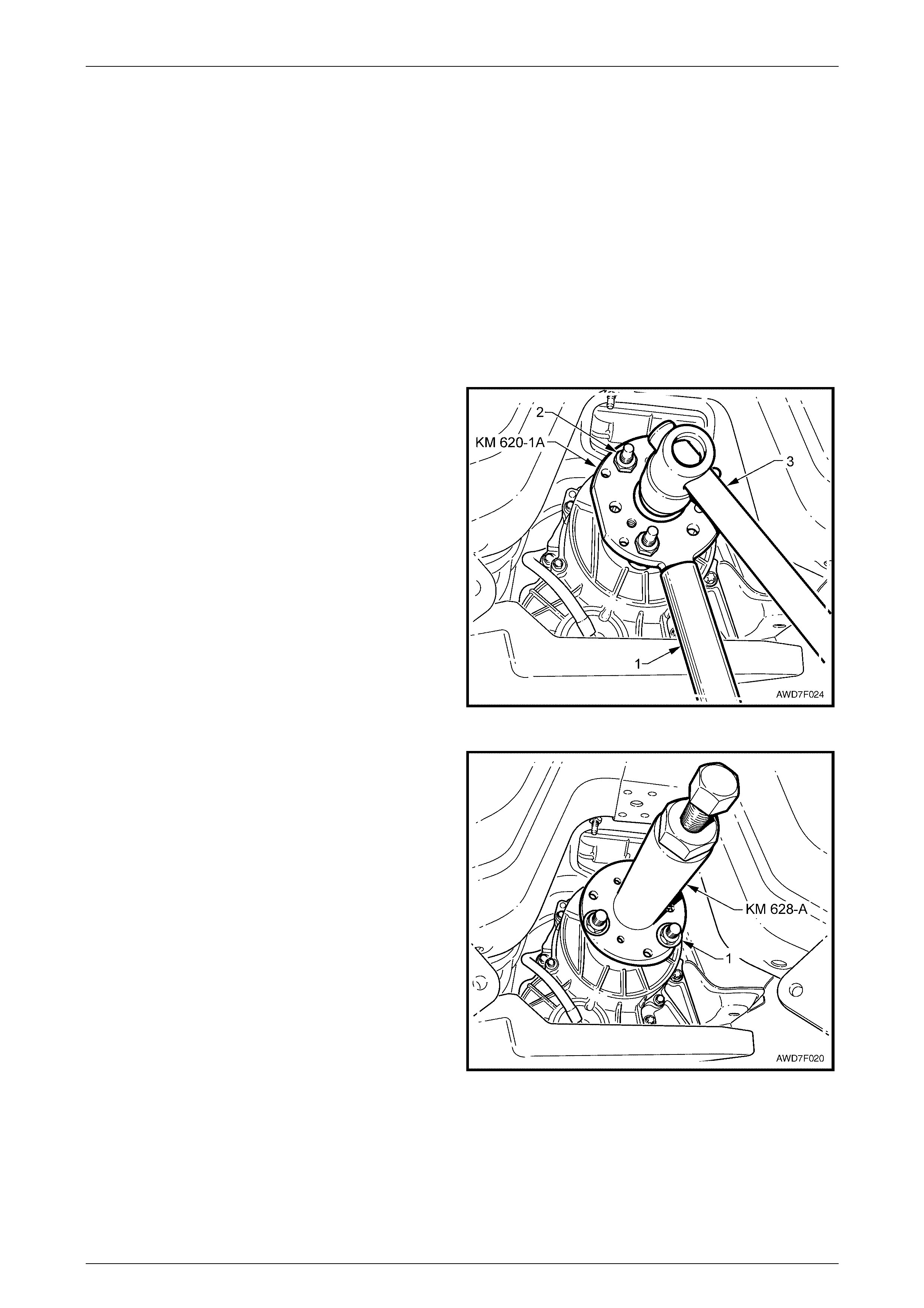
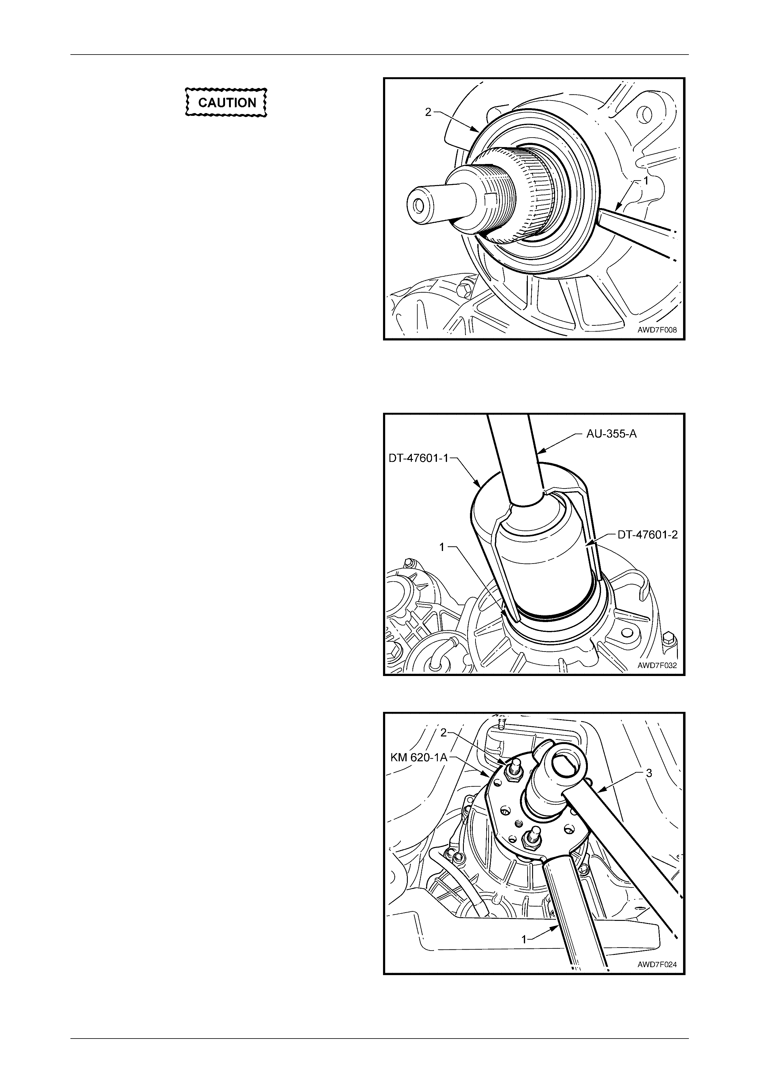
4 Install holding tool KM 620-1A to the output flange and
secure with the three front rubber coupling retaining
nuts (2). Install flat washers over each stud so that,
when the nuts are reinstalled, the holding tool is firmly
clamped to the flange.
NOTE
The holding tool must be firmly clamped to the
flange to avoid damaging the studs.
NOTE
If not previously done so, drill out holes stamped
‘B’ on Tool No. KM-620-1A to 13 mm.
5 With a suitable size length of pipe (1) over the tang of
the holding tool (KM-620-1A), use a 36 mm deep
socket and suitab le soc ket eq uipm ent (3) to loosen ,
then remove the rear output flange retaining nut.
Discard the nut as it must be replaced on reassembly.
Figure 7F – 12
6 Remove the holding tool, KM 620-1A, then install
extracting tool, KM 628-A to the output flange studs.
7 Install a 25 mm spacer (1) (e.g. flat washers) over
each of the studs, then install the coupling nuts,
ensuring that the extracting tool, KM 628-A is firmly
held to the output flange.
NOTE
Unless the extracting tool is clamped up tight to
the flange, there will not be sufficient thread on
the forcing screw to remove the flange from the
transfer case output shaft splines.
Figure 7F – 13
Transfer Case & Adaptor Housing Page 7F – 13
Page 7F-13
Be careful during the seal removal operation,
that damage to the transfer case machined
surfaces does not occur.
8 If the seal is to be removed, use a cold chisel (1) and
hammer, working at the outer perimeter of the seal
casing (2), to remove from the rear transfer case
housing.
Figure 7F – 14
Reinstall
1 Install the seal protector DT-47601-2 over the transfer
case output shaft and push to fully install.
2 Lubricate a new oil seal (1) with Mobilgrease XHP
222, ensuring that the recesses between the seal lips
are filled to approximately 50%, then slide the seal
over the protector.
3 Fully install the seal to the rear transfer case housing,
using seal installer, Tool No. DT-47601-1 and driver,
Tool No. AU-355-A.
4 Remove the seal installation and protector tools.
Figure 7F – 15
5 Lubricate the splines of the transfer case output shaft
with 1 gram of Weicon™ standard grade, anti-seize
grease #37771.
NOTE
This grease is the only product approved for use
in this application and is available in a 10 gram
syringe.
6 Smear the seal surface of the rear output flange with
petroleum jelly (e.g. Vaseline™), then reinstall,
engaging the splines with those on the transfer case
rear output shaft.
7 Using a plastic hammer, tap the flange onto the output
shaft enough to enable the original flange nut to be
installed.
8 Install holding tool KM 620-1A to the rear output
flange, securing with the three front rubber coupling
retaining nuts (2), refer to Step 4 of the Remove
procedure. Use the original flange nut to fully install
the rear output flange. Remove and discard the nut.
Figure 7F – 16

Transfer Case & Adaptor Housing Page 7F – 14
Page 7F-14
9 With a suitable size length of pipe (1) over the tang of the holding tool (KM 620-1A), install a NEW flange nut, then
use a 36 mm deep socket and an accurate torque wrench to tighten the flange nut to the correct torque
specification.
Transfer case rear output flange
retaining nut torque specification........................110 Nm
10 Reinstall the rear propeller shaft. Refer to 2.1 Propeller Shaft, Reinstall, in Section 4C1 Front Propeller Shaft and
Universal Joints in this Service Information.
11 Reinstall the exhaust system. Refer to Section 8B Exhaust System, in this Service Information.
12 Check the transfer case lubric ant lev el. If the level is low , drain and refill the tran sfer cas e. Refer to
2.2 Draining/Filling Transfer Case Lubricant, in this Section.
Transfer Case & Adaptor Housing Page 7F – 15
Page 7F-15
2.5 Transfer Case Support Mount
LT Section No. 04-050
Replace
1 Raise the vehicle and support in a safe manner. Refer to Section 0A General Information, in this Service
Information for details.
2 Remove the catalytic converter bracket by first loosening the nuts from each side and then remove the two bolts
securing the bracket to the transmission adaptor housing. Remove the bracket from the vehicle and set to one side.
NOTE
By removing the bracket intact, the alignment of
the exhaust system will remain undisturbed.
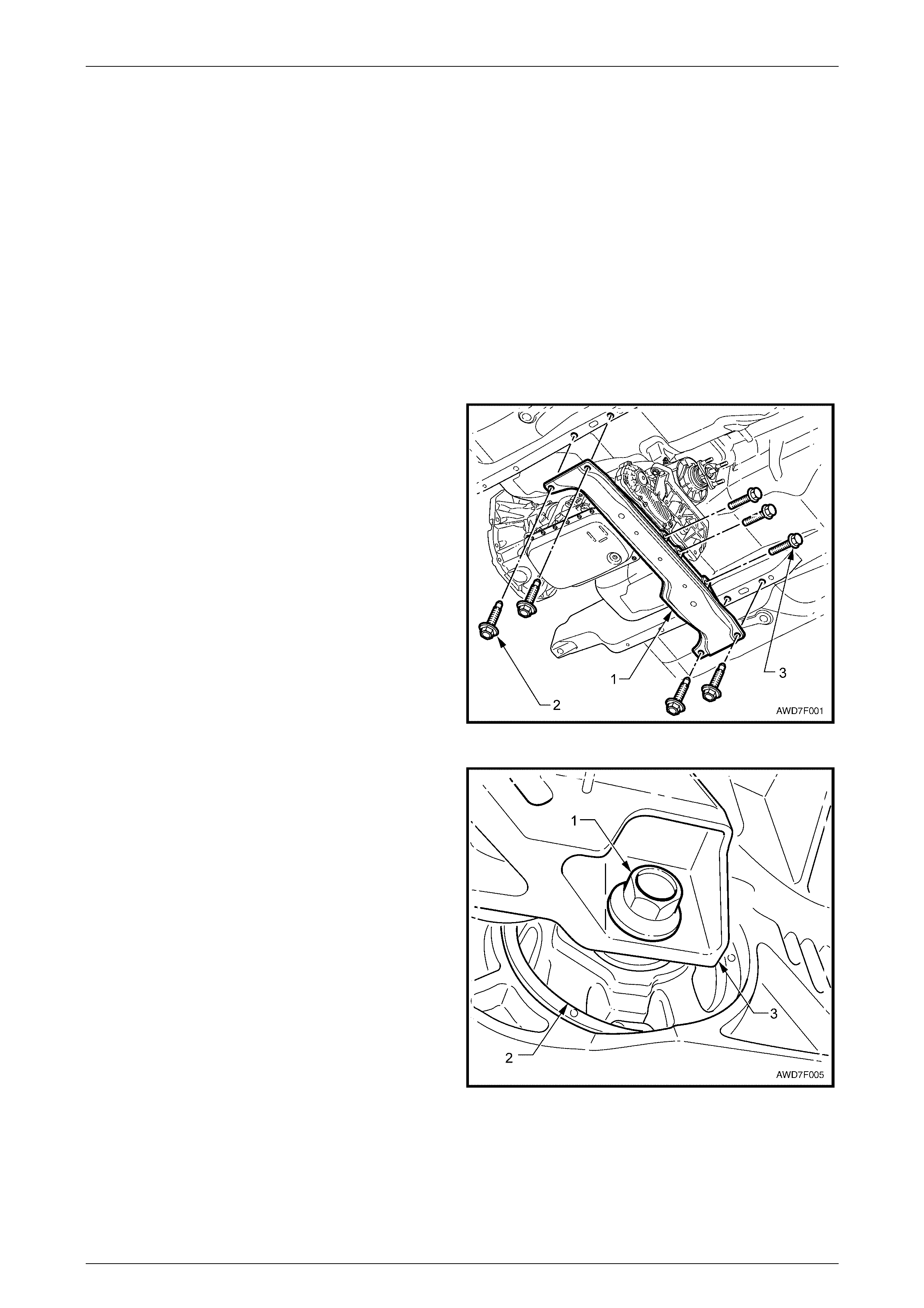
3 Using a felt tipped pen or similar (e.g. W hiteout
correction fluid), mark the position of the rear
crossmember (1) to the underbody side rails.
NOTE
This will assist in realigning the crossmember on
reinstallation.
4 Remove the four bolts (2) attaching the rear
crossmember (1) to the underbody side rails.
5 Remove the three bolts (3) securing the rear
crossmemb er to the transfer c ase mou nt brac ket (not
visible). Remove the crossmember from the vehicle.
NOTE
Support of the transmission is not required at
this time.
Figure 7F – 17
6 With a wooden block and suitable hydraulic lifting
equipment, support the transmission/transfer case on
the transfer case housing.
7 Remove the bolt (1) securing the transfer case rubber
mount (2) to the transfer case rear mounting bracket
(3).
Figure 7F – 18
Transfer Case & Adaptor Housing Page 7F – 16
Page 7F-16
8 Using a felt tipped pen or similar (e.g. Whiteout
correction fluid), mark the position of the transfer case
rear mounting bracket to the vehicle underbody.
NOTE
This will assist in realigning the mounting bracket
on reinstallation.
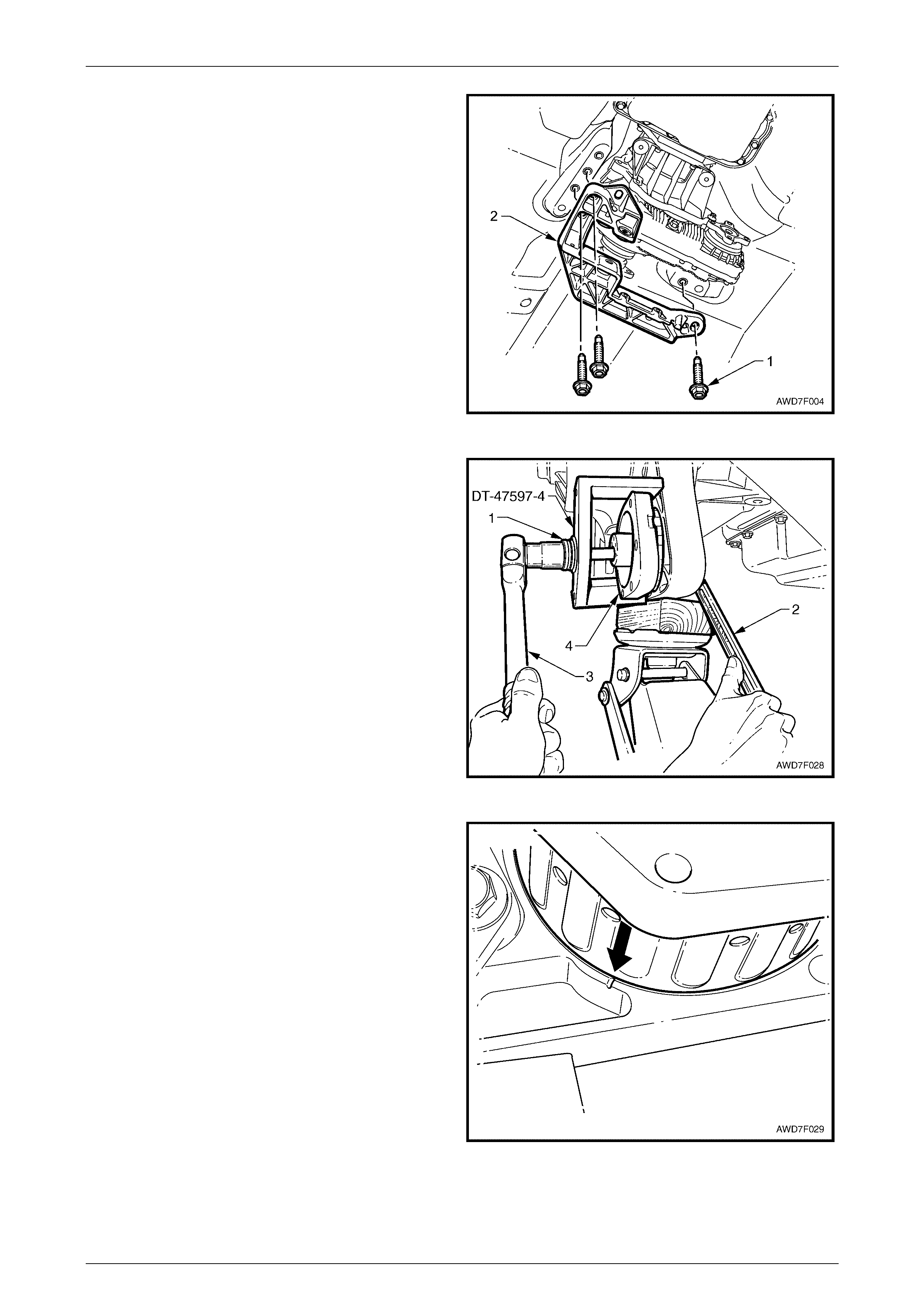
9 Loosen, then remove the three bolts (1) securing the
transfer case rear mounting bracket (2) to the vehicle
underbody.
10 Remove the transfer case rear mounting bracket (2)
from the vehicle.
Figure 7F – 19
11 Lower the rear of the transfer case enough to allow
access to the support mount.
12 Install the thrust bearing (1) to the forcing bolt of Tool
No. DT-47597, then assemble the remover bracket
Tool No. DT-47597-4 and fit these parts to the support
mount, as shown.
13 With the remover disc Tool No. DT-47597-3 installed
over the forcing bolt and rotated to align with the
support mount to be removed, install the flat washer
and nut to complete the removal tool installation.
14 While holding the nut with a ring spanner (2), use
suitable socket equipment (3) to tighten the forcing
bolt, to withdraw the support mount (4) to the rear.
Figure 7F – 20
15 After wiping the support mount surface, both in the
housing and the replace men t mount itself, coat both
outer surface of the replacement mount and the
transfer case housing opening, with a soap solution.
16 Offer up the new support mount to the housing
opening, aligning the arrow moulded into the mount,
with the notch in the housing.
Figure 7F – 21
Transfer Case & Adaptor Housing Page 7F – 17
Page 7F-17
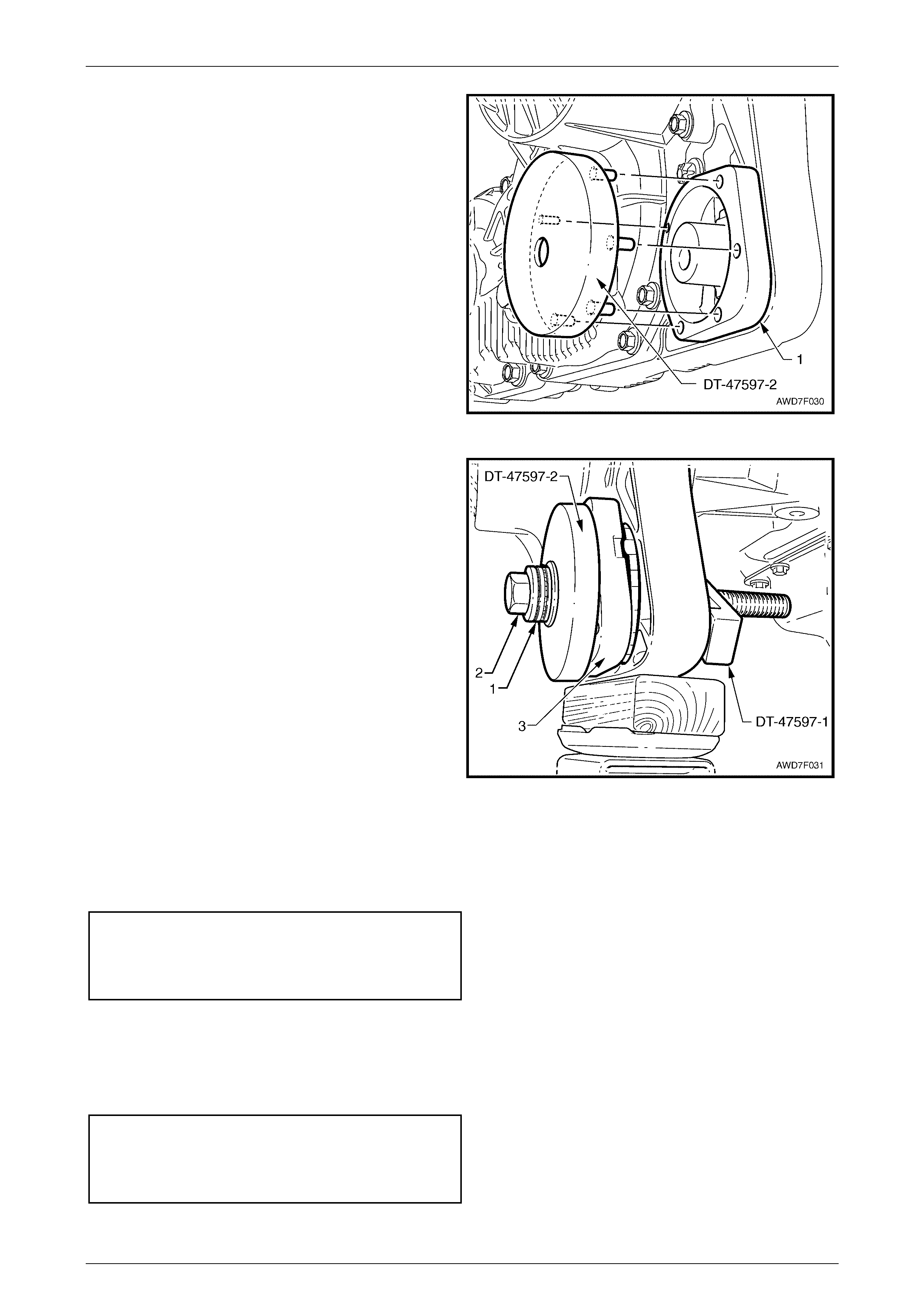
17 Assemble installer plate, Tool No. DT-47597-2,
aligning the five pins on the installer plate with the
corresponding holes in the support mount (1) rear
surface.
NOTE
The location of the smaller diameter pin is
closest to the transfer case.
Figure 7F – 22
18 Install the thrust race (1) over the forcing bolt (2), then
install through the installing plate DT-47597-2 and the
new mount (3), shown here, partially installed.
19 Install the stepped installer bracket, Tool No. DT-
47597-1 over the bolt, aligning with the transfer case
housing, as shown.
20 After installing a flat washer and nut, hold the nut with
a ring spanner, then tighten the forcing bolt using
suitable socket equipment, to fully install the mount
into the transfer case housing.
Figure 7F – 23
21 Reinstall the transfer case mount bracket, aligning the bracket with the marks made on the underbody, before
removal.
22 Reinstall the three bracket to underbody bolts and the transfer case mount to bracket bolt, tightening all transfer
case bracket bolts to the correct torque specification.
Transfer case bracket to underbody
bolt torque specification........................................58 Nm
Transfer case mount to bracket
bolt torque specification......................................100 Nm
23 Lower the transfer case, then remove the lifting equipment.
24 Reinstall the rear crossmember, aligning the crossmember with the marks made on the underbody, before removal.
25 Reinstall the three crossmember to transfer case bolts and four crossmember to underbody side rail retaining bolts,
and tighten all to the correct torque specification.
Rear crossmember to transfer
case bracket bolt torque specification ..................54 Nm
Rear crossmember to underbody
side rail bolt torque specification ..........................54 Nm

Transfer Case & Adaptor Housing Page 7F – 18
Page 7F-18
26 Reinstall the catalytic converter bracket tightening the adaptor housing bolts and the catalytic converter nuts to the
correct torque specification.
Catalytic converter bracket bolt to
adaptor housing torque specification....................25 Nm
Catalytic converter bracket nut to
catalytic conv ert er torque spe c ific atio n.................25 Nm
Transfer Case & Adaptor Housing Page 7F – 19
Page 7F-19
3 Major Service Operations
3.1 Transfer Case
LT Section No: – 04-050
Remove
1 Raise the vehicle and support in a safe manner. Refer to Section 0A General Information, in this Service
Information for details.
2 Remove the catalytic converter bracket by first removing the nuts from each side and then two bolts securing the
bracket to the transmission adaptor housing.
NOTE
By removing the bracket intact, the alignment of
the exhaust system will remain undisturbed.
3 Remove the exhaust system, from the rear of the two catalytic converter, rearward. Refer to
Section 8B Exhaust System in this Service Information.
4 Remove the rear propeller shaft. Refer to Section 4C1 Rear Propeller Shaft & Universal Joints, in this Service
Information.
5 Remove the front propeller shaft. Refer to Section 4C2 Front Propeller Shaft & Universal Joints, in this Service
Information.
6 Using a felt tipped pen or similar (e.g. W hiteout
correction fluid), mark the position of the rear
crossmember (1) to the underbody side rails.
NOTE
This will assist in realigning the crossmember on
reinstallation.
7 Remove the four bolts (2) attaching the rear
crossmember (1) to the underbody side rails.
8 Remove the three bolts (3) securing the rear
crossmemb er to the transfer c ase mou nt brac ket (not
visible). Remove the crossmember from the vehicle.
NOTE
Support of the transmission is not required at
this time.
Figure 7F – 24
Transfer Case & Adaptor Housing Page 7F – 20
Page 7F-20
9 With a wooden block and suitable hydraulic lifting
equipment, support the adaptor housing or the rear of
the transmission oil pan.
10 Remove the bolt (1) securing the transfer case rubber
mount (2) to the transfer case rear mounting bracket
(3).
Figure 7F – 25
11 Using a felt tipped pen or similar (e.g. W hiteout
correction fluid), mark the position of the transfer case
rear mounting bracket to the vehicle underbody.
NOTE
This will assist in realigning the mounting bracket
on reinstallation.
12 Loosen, then remove the three bolts (1) securing the
transfer case rear mounting bracket (2) to the vehicle
underbody.
13 Remove the transfer case rear mounting bracket (2)
from the vehicle.
Figure 7F – 26
14 Slowly lower the hydraulic support under the
transmission (or adaptor housing), enough to gain
access to the vehicle speed sensor retaining screw
(2).
15 Disconnect the wiring harness connector (1) from the
vehicle speed sensor.
16 Remove the vehicle speed sensor retaining screw (2),
then twist and pull on the sensor to remove it from the
adaptor housing.
NOTE
Removing the vehicle speed sensor is a
precautionary measure, to avoid possible
damage from the adaptor shaft pick-up ring
teeth.
Figure 7F – 27
17 Disconnect the transfer case breather hose from the vent fitting and secure to one side.
Transfer Case & Adaptor Housing Page 7F – 21
Page 7F-21
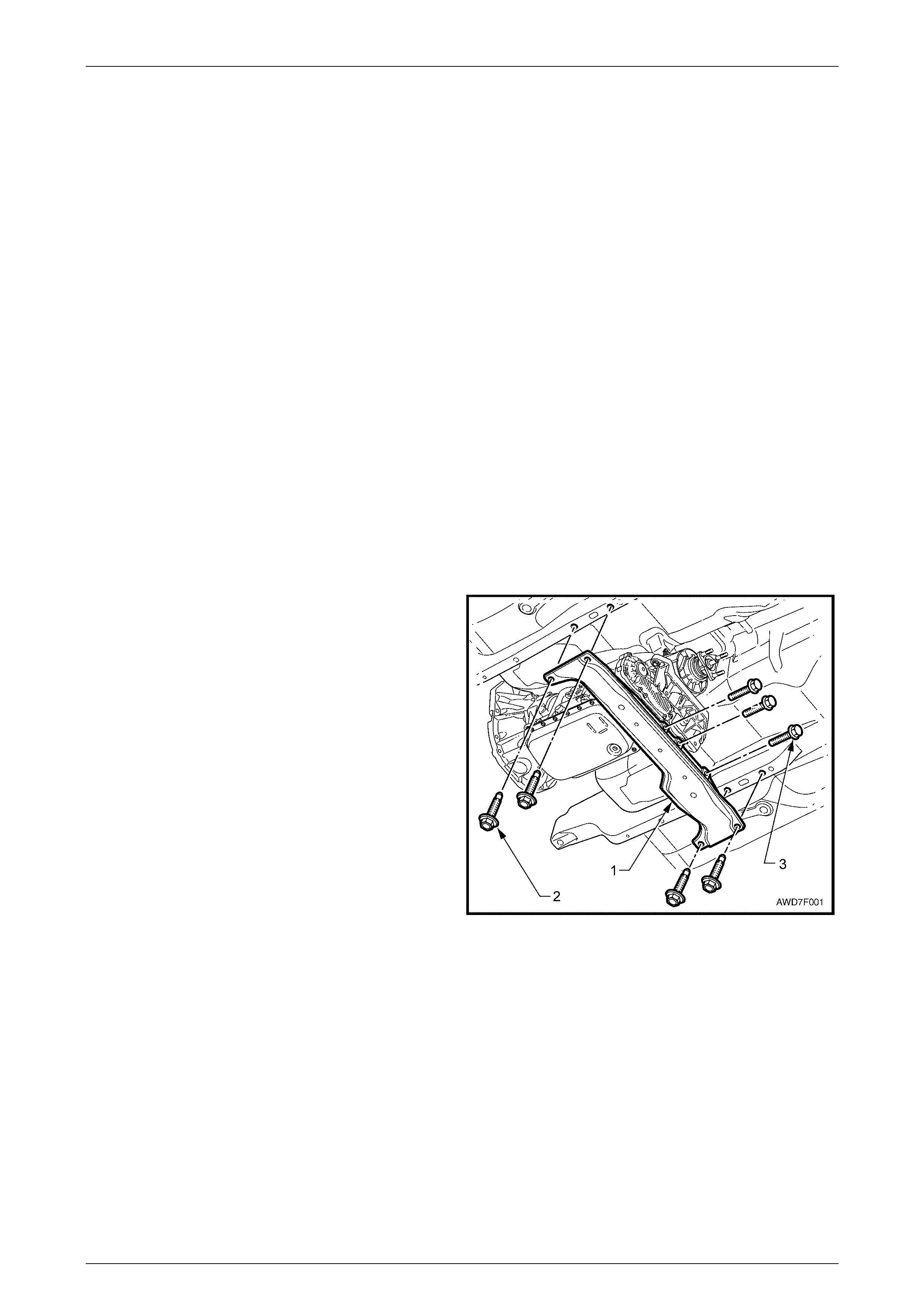
18 Using an E14 Torx socket and suitable socket equipment, remove the five transfer case (1) to adaptor housing (2)
attaching bolts (3), taking note of the two longer bolt locations (4). Refer to Figure 7F-28.
Figure 7F – 28
19 Remove the sixth bolt (1) from the front of the transfer
case, adjacent to the front propeller shaft flange.
Figure 7F – 29
20 While supporting the transfer case, pull rearward to dislodge it from the two locating dowel rings. Continue to pull
rearwards until the adaptor shaft splines are clear of the transmission mainshaft.
21 Carefully lower the transfer case and remove it from the vehicle.

Transfer Case & Adaptor Housing Page 7F – 22
Page 7F-22
Reinstall
Reinstallation of the transfer case is the reverse to the removal operation, except for the following items:
1 Inspect the seal surface at the front of the adaptor shaft for excess wear in the seal area. If deep grooving is
evident, then the adaptor shaft should be replaced. If considered necessary to replace the adaptor shaft because of
wear, then it would also be strongly recommended that the adaptor housing be removed and the seal replaced.
Refer to 3.4 Adaptor Housing Oil Seal, Replace, in this Section.
2 Lubricate the internal splines and seal surface of the adaptor shaft with molybdenum disulphide grease.
3 After checking that the adaptor shaft is fully installed into the transfer case, raise the transfer case with suitable
hydraulic lifting equipment and offer the assembly up to the adaptor housing.
4 While aligning the transfer case front face parallel to the adaptor housing machined rear face, move the transfer
case forward, engaging the splines of the adaptor shaft with those of the transmission output shaft. If required, rock
the transfer case output flange back and forth, to assist with spline engagement.
5 Push the transfer case forward, to engage both dowel rings, install the six bolts securing the transfer case to the
adaptor housing and tighten to the correct torque specification.
Transfer case to adaptor housing
bolt torque specification........................................45 Nm
6 Reinstall the breather hose to the transfer case vent fitting.
7 Reinstall the vehicle speed sensor to the adaptor housing, then secure with the bracket screw, tightening to the
correct torque specification. Reinstall the wiring harness connector to the speed sensor.
Vehicle speed sensor bracket
screw torque specification...................................5.0 Nm
8 Reinstall the transfer case mount bracket and install the bracket to transfer case mount bolt, but do not fully tighten
at this time.
9 Raise the transmission/transfer case assembly, aligning the transfer case bracket with the marks made on the
underbody, before removal.
10 Reinstall the three transfer case bracket to underbody bolts. Lower the transfer case, then remove the lifting
equipment.
11 Tighten all transfer case bracket bolts to the correct torque specification.
Transfer case bracket to underbody
bolt torque specification........................................58 Nm
Transfer case mount to bracket
bolt torque specification......................................100 Nm
12 Check that the transfer case lubricant level is correct. Refer to 2.1 Checking Transfer Case Lubricant Level in this
Section.
13 Reinstall the rear crossmember, aligning the crossmember with the marks made on the underbody before removal.
14 Reinstall the three crossmember to transfer case bolts and four crossmember to underbody side rail retaining bolts,
and tighten all to the correct torque specification.
Rear crossmember to transfer
case bracket bolt torque specification ..................54 Nm
Rear crossmember to underbody
side rail bolt torque specification ..........................54 Nm
15 Reinstall the catalytic converter bracket tightening the adaptor housing bolts and the catalytic converter nuts, to the
correct torque specification.
Catalytic converter bracket bolt to
adaptor housing torque specification....................25 Nm
Catalytic converter bracket nut to
catalytic conv ert er torque spe c ific atio n.................25 Nm

Transfer Case & Adaptor Housing Page 7F – 23
Page 7F-23
16 Reinstall both propeller shafts. Refer to Section 4C1 Rear Propeller Shaft & Universal Joints and
Section 4C2 Front Propeller Shaft & Universal Joints in this Service Information.
17 Reinstall the exhaust system. Refer to Section 8B Exhaust System, in this Service Information.
18 Check the automatic transmission fluid level. Refer to Section 7C4 Automatic Transmission - On-Vehicle Servicing,
in the MY 2004 AWD Wagon Service Information.
Transfer Case & Adaptor Housing Page 7F – 24
Page 7F-24
3.2 Transfer Case, Input Shaft Oil Seal
LT Section No: 04-050
Replace
1 Remove the transfer case from the adaptor housing. Refer to 3.1 Transfer Case, Remove, in this Section.
2 To remove the adaptor shaft (1) from the front of the
transfer case, it will be necessary to use a lever such
as a large screwdriver (2), between the adaptor shaft
step and the oil seal, as show n.
Some resistance will be felt, until the snap ring on the
end of the shaft is dislodged from the groove in the
inner end of the transfer case input shaft. Remove the
snap ring from the adaptor shaft and discard.
Figure 7F – 30
3 Use a small screwdriver or wire hook to remove the O-
ring seal (1) from the inside of the front input shaft.
Discard the removed O-ring seal.
Be careful during the seal removal operation,
that damage to the transfer case machined
surfaces does not occur.
4 To remove the front input shaft oil seal (2) from the
transfer case front housing (3), use a cold chisel and
hammer, working around the outer seal perimeter of
the seal housing.
Figure 7F – 31
Transfer Case & Adaptor Housing Page 7F – 25
Page 7F-25
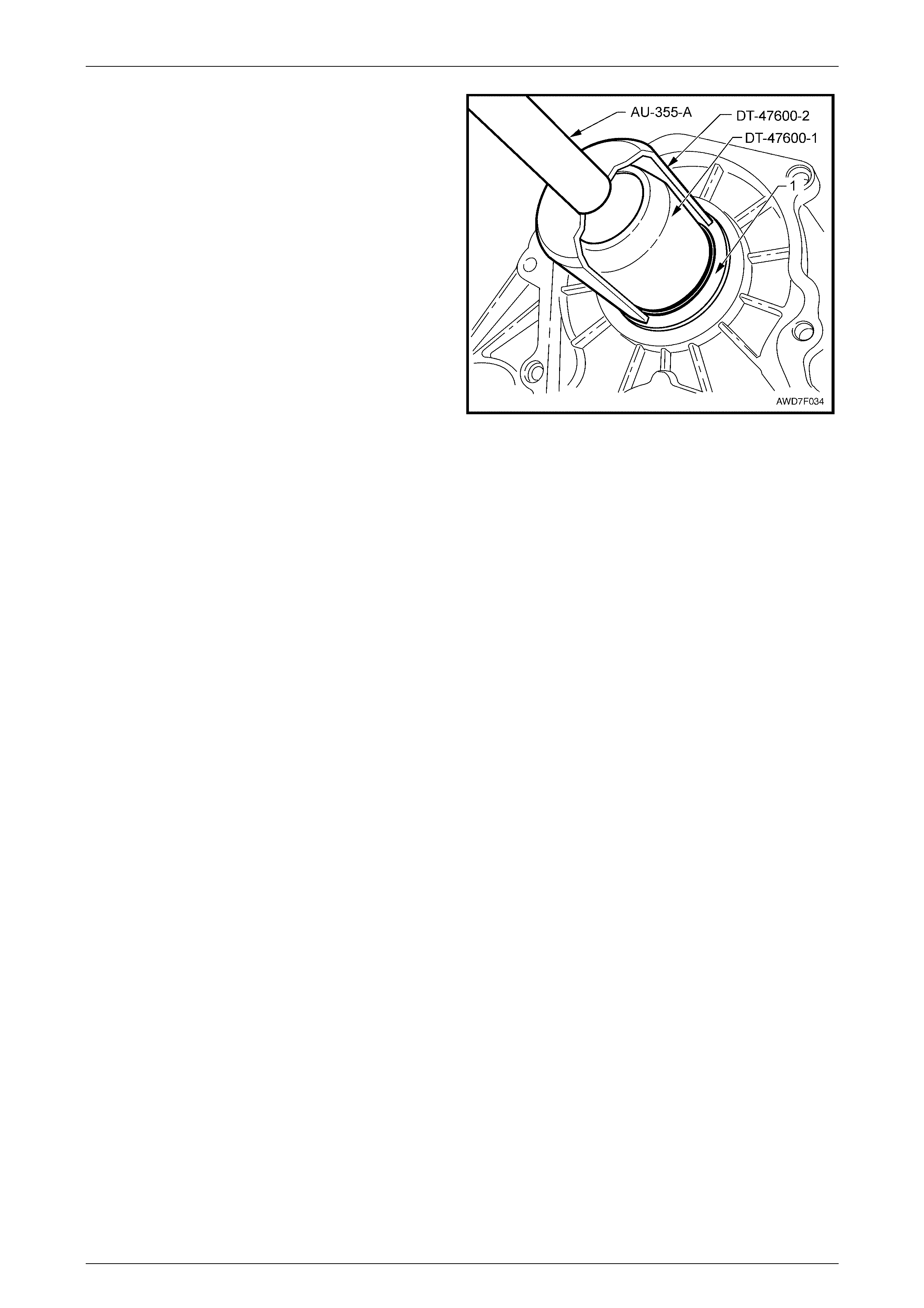
5 Install the seal protector DT-47600-1 over the transfer
case, front input shaft and push to fully install.
6 Lubricate a new oil seal (1) with Mobilgrease XHP
222, ensuring that the recesses between the seal lips
are filled to approximately 50%, then slide the seal
over the protector.
7 Install driver, Tool No. AU 355-A into seal installer,
Tool No. DT-47600-2, then install the seal to the
transfer case front housing until the seal is fully
installed.
8 Remove the seal installation and protector tools.
9 Lubricate a new O-ring seal with a smear of
Mobilgrease XHP 222 and install into the groove at the
front of the input shaft.
10 Lubricate the internal splines of the transfer case front
adaptor shaft with 1 gram of Weicon™ standard
grade, anti-se ize grease #37771.
NOTE
This grease is the only product approved for use
in this application and is available in a 10 gram
syringe.
Figure 7F – 32
11 After fitting a new snap ring to the end of the adaptor shaft, reinstall the adaptor shaft to the input shaft of the
transfer case. It should only be necessary to use light force to fully install the shaft, engaging the snap ring with the
groove in the input shaft.
12 Reinstall the transfer case to the adaptor housing. Refer to 3.1 Transfer Case, Reinstall, in this S ect ion.
Transfer Case & Adaptor Housing Page 7F – 26
Page 7F-26
3.3 Transmission Adaptor Housing
LT Section No: 04-050
Remove
1 Remove the transfer case from the adaptor housing. Refer to 3.1 Transfer Case, Remove, in this Section.
2 If the vehicle speed sensor was not removed during
the transfer case removal operations, proceed as
detailed nex t:
a With the rear of the automatic transmission
lowered at the rear to gain access, disconnect
the wiring harness connector (1) from the vehicle
speed sensor.
b Remove the vehicle speed sensor retaining
screw (2), then twist and pull on the sensor to
remove it from the adaptor housing.
Figure 7F – 33
3 Place a drain tray under the rear of the automatic transmission, to catch residual automatic transmission fluid, once
the seal between the transmission and the adaptor housing is broken.
4 Using an E14 Torx socket and suitable equipment,
remove the six bolts securing the adaptor housing to
the rear of the automatic transmission.
NOTE
The view shows the two lower bolts (1).
If the transmission oil pan feels hot, take care
to avoid scalding from the hot automatic
transmission fluid that will flow from the rear
of the transmission.
5 If required, tap the adaptor housing with a rubber
hammer to break the square section O-ring seal.
6 Remove the adaptor housing from the vehicle.
Figure 7F – 34

Transfer Case & Adaptor Housing Page 7F – 27
Page 7F-27
Reinstall
Apart from the items detailed here, the reinstallation procedure is the reverse to the removal operation.
1 After cleaning the mating surfaces of the transmission and the adaptor housing, install a new square section, O-
ring seal, that has been lubricated with a smear of petroleum jelly (e.g. Vaseline™).
2 Reinstall the adaptor housing to the rear of the automatic transmission, reinstall the six Torx headed bolts and
tighten to the correct torque specification.
Adaptor housing to transm is si on case
bolt torque specification........................................45 Nm
3 Reinstall the transfer case to the adaptor housing. Refer to 3.1 Transfer Case, Reinstall, in this Section.
4 Check the automatic transmission fluid level. Refer to Section 7C4 Automatic Transmission - On-Vehicle Servicing,
in the MY 2004 AWD Wagon Service Information.
Transfer Case & Adaptor Housing Page 7F – 28
Page 7F-28
3.4 Transmission Adaptor Housing Oil Seal
LT Section No: 04-050
Replace
1 Remove the adaptor housing from the rear of the automatic transmission. Refer to 3.3 Adaptor Housing, Remove,
in this Section.
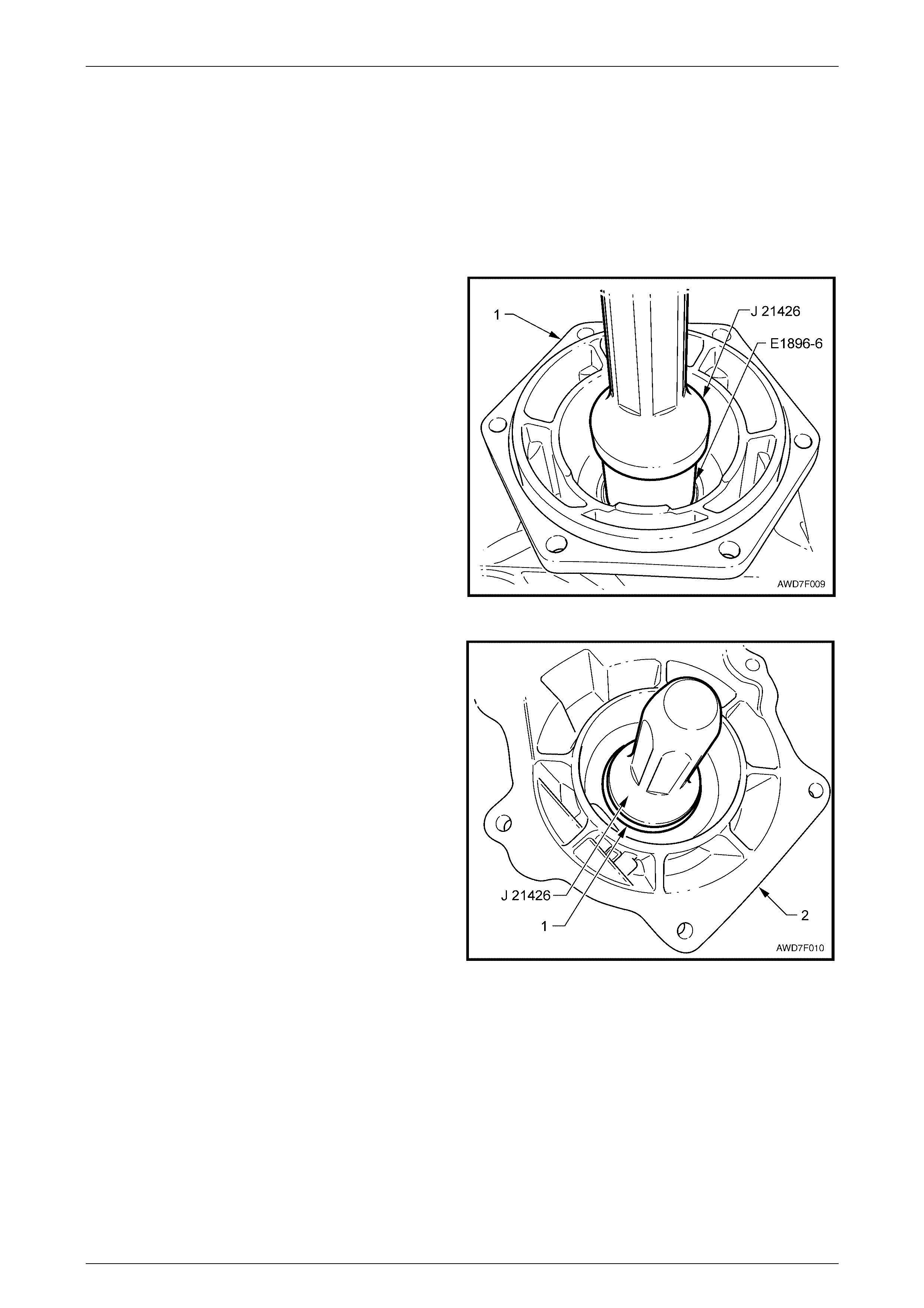
2 With the adaptor housing (1) supported on a flat
surface, use sleeve, Tool No. E1891-6 (or 3A8-6) or a
suitable piece of pipe (OD 57 mm) and seal installer,
Tool No. J 21426 to drive the seal into the rear section
of the adaptor housing. Discard the removed seal.
Figure 7F – 35
3 Install a new oil seal (1) to the adaptor housing (2),
using seal installer J 21426, working from the rear to
the front of the housing, as shown.
4 Lubricate the seal lips with petroleum jelly (e.g.
Vaseline™), before reinstalling the adaptor housing
to the rear of the transmission. Refer to 3.3 Adaptor
Housing, Reinstall, in this Section.
Figure 7F – 36

Transfer Case & Adaptor Housing Page 7F – 29
Page 7F-29
4 Transfer Case S ymptom
Diagnosis
4.1 Preliminary Diagnosis
System Operation
Review the system operation to familiarise yourself with the system functions. Refer to 1 General Description, in this
Section.
As the internal components are not serviced separately, should an internal component failure be determined, then the
transfer case must be replaced as an assembly.
Visual/Physical Inspection
1 Inspect the easily accessible or visual system components for obvious damage, or for conditions that could cause
the symptom.
2 Inspect for the correct lubrication type and level. As this assembly has a very specific lubrication requirement, if in
doubt, drain the lubricant and refill with the known correct fluid. Refer to 2.1 Checking Transfer Case Lubricant
Level and 2.2 Draining/Filling Transfer Case Lubricant, in this Section.
Symptom List
Refer to the appropriate symptom diagnostic procedure from the following list, to diagnose the symptom:
4.2 Popping Noise
4.3 Whine or Rumble No ise
4.4 Growl or Grinding Noise
4.5 Clunk During Acceleration and Deceleration
4.6 No Front or Rear Drive
4.7 Lubricant Leak Diagnosis

Transfer Case & Adaptor Housing Page 7F – 30
Page 7F-30
4.2 Popping Noise
Definition: A faulty internal transfer case component that causes a popping noise in the transfer case.
Cause Correction
Internal Damage • Probable gear teeth damage, that has caused subsequent bearing failure due to
metallic debris. Replace transfer case. Refer to 3.1 Transfer Case, in this Section.

Transfer Case & Adaptor Housing Page 7F – 31
Page 7F-31
4.3 Whine or Rumble Noise
Definition: A faulty internal transfer case component that causes a whine or rumbling noise in the transfer case.
Cause Correction
Faulty Bearings • Failure of an internal bearing or bearings. Replace transfer case. Refer to
3.1 Transfer Case, in this Section.

Transfer Case & Adaptor Housing Page 7F – 32
Page 7F-32
4.4 Growl or Grinding Noise
Definition: A faulty internal transfer case component that causes a growl or grinding noise in the transfer case.
Cause Correction
Internal Damage • Possible damage to the planetary carrier pinion teeth, the carrier, ring gear and/or
sun gear teeth.
• Loss of lubricant w ould contr ibute to the damage noted. Repl ace trans fer cas e.
Refer to 3.1 Transfer Case, in this Section.

Transfer Case & Adaptor Housing Page 7F – 33
Page 7F-33
4.5 Clunk During Acceleration and
Deceleration
Definition: During acceleration or deceleration, a clunk is heard or felt from the transfer case.
Cause Correction
Incorrect lubr ica nt lev el • Inspect the transfer case for correct fluid level. Refer to 2.1 Checking Tran sfer
Case Lubricant Level, in this Section. If lubricant level is low, then the reason must
be determined and corrected before placing the vehicle back into service.
Internal Damage • Excessive backlash in the geartrain caused by teeth wear. Replace transfer case.
Refer to 3.1 Transfer Case, in this Section.
Loose output flange nut • Output flange retaining nut worked loose, allowing flange splines to wear. If flange
replacement does not correct the condition, replace the transfer case. Refer to
3.1 Transfer Case, in this Section.

Transfer Case & Adaptor Housing Page 7F – 34
Page 7F-34
4.6 No Front or Rear Drive
Definition: The transfer case in not delivering engine torque to either propeller shaft
Cause Correction
Internal Damage • Probable planetary gear set damage, that creates a permanent neutral condition.
Replace transfer case. Refer to 3.1 Transfer Case, in this Section.

Transfer Case & Adaptor Housing Page 7F – 35
Page 7F-35
4.7 Lubricant Leak Diagnosis
Definition: A visible indication of an external leak is evident from the transfer case.
Cause Correction
Drain or fill plug • Replace the leaking plug and seal. Refer to
2.2 Draining/Filling Transfer Case Lubricant, in this Section.
Rear output shaft seal leaking • Overfilled or incorr ect tran sfer cas e lubric ant lev el. Refer to
2.1 Checking Transfer Case Lubricant Level, in this Section.
• Blocked vent. Check for correct routing, absence of kinking hose. Clear blocked
vent line.
• Seal improperly installed, worn or damaged. Inspect rear output flange seal
surface for excessive wear or damage. Replace rear output shaft flange and oil
seal. Refer to 2.4 Transfer Case Rear Output Flange and Oil Seal, in this Section.
• Seal bore damaged or housing is cracked. Replace transfer case. Refer to
3.1 Transfer Case, in this Section.
• Rear output shaft bearing worn. Replace transfer case. Refer to
3.1 Transfer Case, in this Section.
Front output shaft seal leaking • Overfilled or incorr ect tran sfer cas e lubric ant lev el. Refer to
2.1 Checking Transfer Case Lubricant Level, in this Section.
• Blocked vent. Check for correct routing, or a kinked hose. Clear blocked vent line
or replace vent line as required.
• Seal improperly installed, worn or damaged. Inspect front output seal surface for
excessive wear or damage. Replace front output shaft slinger and oil seal. Refer
to 2.3 Transfer Case Front Output Flange, Slinger and Oil Seal, in this Section.
• Seal bore damaged or housing is cracked. Replace transfer case. Refer to
3.1 Transfer Case, in this Section.
• Front output shaft bearing worn. Replace transfer case. Refer to
3.1 Transfer Case, in this Section.
Leaking from the vent • Transfer case is overfilled. Restore to correct level. Refer to
2.1 Checking Transfer Case Lubricant Level, in this Section.
• Vent hose is blocked. Inspect for kinking or end blocked with mud or other foreign
material. Clear blockage.
Adaptor Housing Fluid Leak • Check that the fluid is automatic transmission fluid. If not, refer to
Front input shaft oil seal leaking, in this Table. Otherwise continue.
• Remove transfer case and inspect adaptor shaft for wear or damage at the seal
contact area. Refer to 3.1 Transfer Case, in this Section.
• Replace adaptor housing oil seal. Refer to 3.4 Transmission Adaptor Housing Oil
Seal, in this Section.
Front input shaft seal leaking • Overfilled or incorr ect tran sfer cas e lubric ant lev el. Refer to
2.1 Checking Transfer Case Lubricant Level, in this Section.
• Blocked vent. Check for correct routing, or kinked hose. Clear blocked vent line or
replace vent as required.
• Seal improperly installed, worn or damaged. Inspect front input seal surface for
excessive wear or damage. Replace front input shaft oil seal. Refer to
3.2 Transfer Case, Input Shaft Oil Seal, in this Section.
• Seal bore damaged or housing is cracked. Replace transfer case. Refer to
3.1 Transfer Case, in this Section.
• Front input shaft bearing worn. Replace transfer case. Refer to
3.1 Transfer Case, in this Section.

Transfer Case & Adaptor Housing Page 7F – 36
Page 7F-36
Cause Correction
Lubricant leak from the transfer
case housing join • Replace the transfer case. Refer to 3.1 Transfer Case, in this Section.
Lubricant leak from either of
the transfer case housings • Replace the transfer case. Refer to 3.1 Transfer Case, in this Section.

Transfer Case & Adaptor Housing Page 7F – 37
Page 7F-37
5 Specifications
General
Make................................................................................................ New Venture Gear (NVG)
Model............................................................................................................................ NV124
Type.................................................................................................... Full Time Single Speed
Torque Split............................................................................................38/62% Front to Rear
Gearing
Input from Transmission Output Shaft..............................................3 pinion Planetary Carrier
Output to Rear Final Drive .......................................................................Planetary Ring Gear
Output to Front Final Drive........................................................Sun Gear and Helical Gearing
Lubricants
Lubricant Type .................................................................................................Esso MTF-LT-1
Quantity – Dry Fill........................................................................................................240 ml
– Service Refill (after Draining) ...........................................150 ml (approximately)
Oil Seal Lip and O-Ring Lubricant..........................................................Mobilgrease XHP 222
Front Input/Output and Rear Output Shaft Splines................Weicon #73331 Standard Grade
Anti-Seize Grease

Transfer Case & Adaptor Housing Page 7F – 38
Page 7F-38
6 Torque Wrench Specifications
Adaptor Housing to Transmission Case Bolt...........................................45 Nm
Catalytic Converter Bracket to Adaptor Housing Bolt ..............................25 Nm
Catalytic Converter Bracket to Catalytic Converter Nut...........................25 Nm
Rear Crossmember to Transfer Case Bracket Bolt..................................54 Nm
Rear Crossmember to Underbody Side Rail Bolt.....................................54 Nm
Transfer Case Bracket to Underbody Bolt...............................................58 Nm
Transfer Case Drain Plug ........................................................................32 Nm
Transfer Case Filler Plug.........................................................................32 Nm
Transfer Case Mount to Bracket Bolt.....................................................100 Nm
Transfer Case Rear Output Flange Nut.................................................110 Nm
Vehicle Speed Sensor Bracket Screw....................................................5.0 Nm
Transfer Case to Adaptor Housing Bolt...................................................45 Nm
Transfer Case & Adaptor Housing Page 7F – 39
Page 7F-39
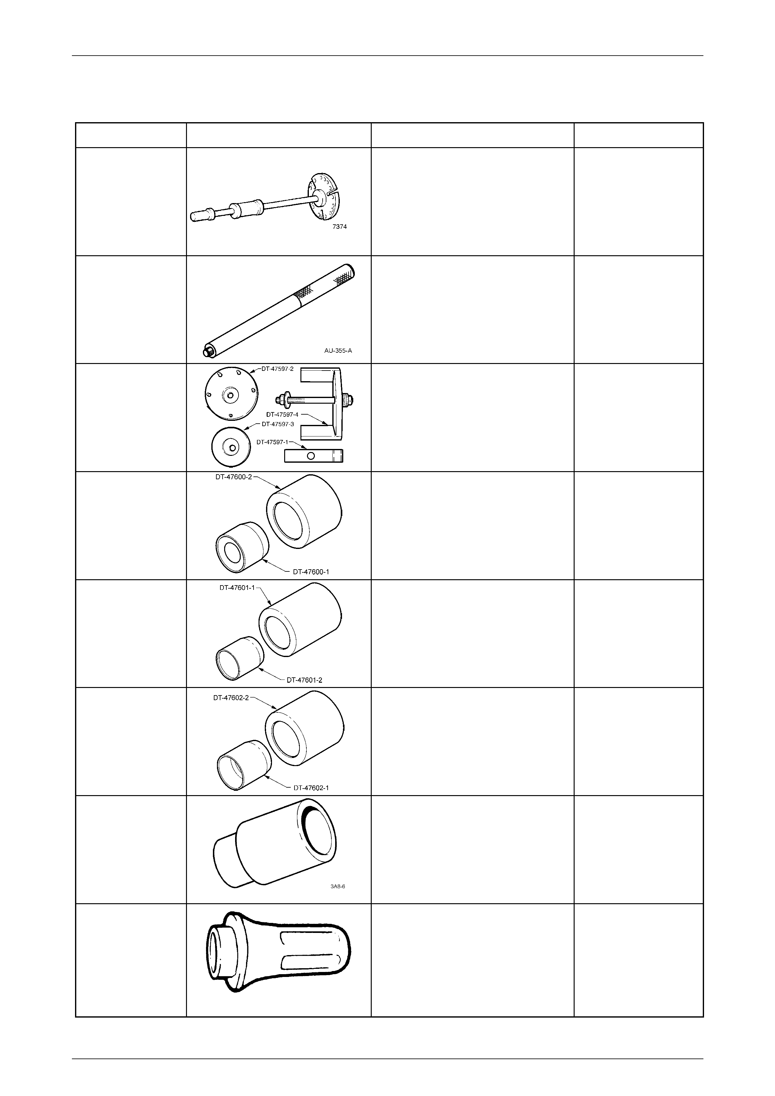
7 Special Tools
Tool Number Illustration Description Tool Classification
7374
Slide Hammer
Used with three screws to remove the
front output flange from the transfer
case.
Previously released.
Desirable
AU-355-A
Driver
Used in conjunction with various
installers.
Previously released.
Available
DT-47597
Rear Mount Remover/Installer
Used to remove and install the rear
support mount from/to the tran sfer
case.
New release.
Available
DT-47600
Seal Protector & Installer
Used to protect and install the front
input shaft oil seal to the transfer
case.
New release.
Available
DT-47601
Seal Protector & Installer
Used to protect and install the rear
output shaft oil seal to the transfer
case.
New release.
Available
DT-47602
Seal Protector & Installer
Used to protect and install the front
output shaft oil seal to the transfer
case.
New release
Available
E1896-6
Sleeve
Used in conjunction with seal installer
J 21426 to remove the oil seal from
the adaptor housing.
Previously released.
Unique
J 21426
Seal Installer
Used in conjunction with sleeve
E1896-6 to remove the oil seal from
the adaptor housing and to install the
new seal.
Previously released.
Unique
Transfer Case & Adaptor Housing Page 7F – 40
Page 7F-40
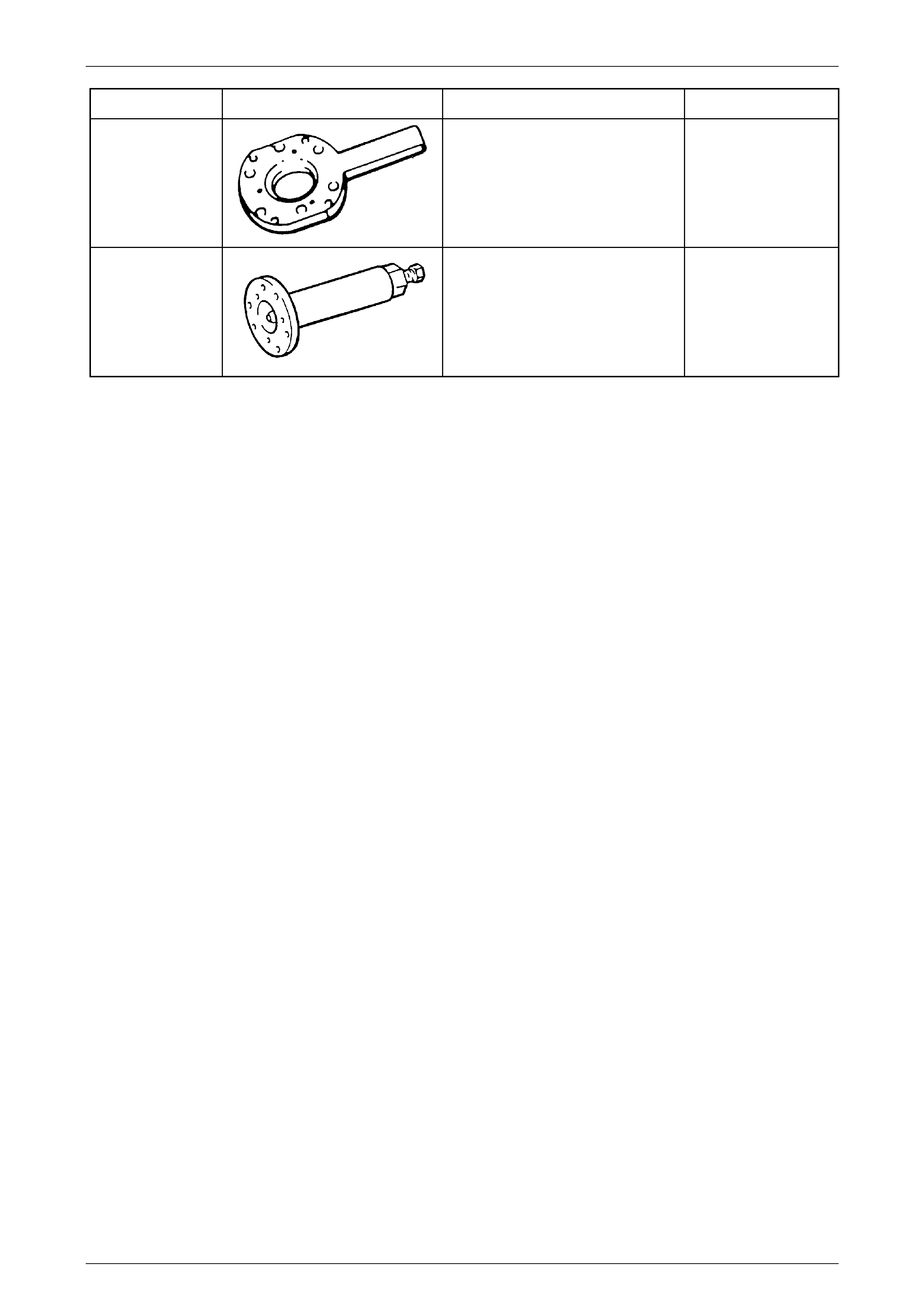
Tool Number Illustration Description Tool Classification
KM 620-1A
Holding Tool
Part of Tool No. KM 620-A. The
holding tool is used to hold the output
flange while removing the flange nut.
Previously released.
Unique
KM 628-A
Extractor
Used to remove the rear output flange
from the rear of the transfer case.
Previously released.
Unique