
Exhaust System Page 8B –1
Page 8B–1
Section 8B
Exhaust System
ATTENTION
Before performing any Service Operation or other procedure described in this Section, refer to Section 00
Cautions And Notes for correct workshop practices with regard to safety and/or property damage.
1 General Information............................................................................................................................... 2
2 Service Operations................................................................................................................................3
2.1 Service Notes..........................................................................................................................................................3
2.2 Exhaust Fitment and Tightening Sequence.........................................................................................................4
Installation ..............................................................................................................................................................4
Tightening Sequence..........................................................................................................................................4
2.3 Exhaust Manifold Install atio n................................................................................................................................6
2.4 Exhaust System Layout.........................................................................................................................................7
2.5 Exhaust System Clearances..................................................................................................................................9
2.6 Exhaust System Heat Shields.............................................................................................................................11
3 Exhaust System Diagnosis................................................................................................................. 13
4 Specifications....................................................................................................................................... 14
5 Torque Wrench Specifications........................................................................................................... 15

Exhaust System Page 8B –2
Page 8B–2
1 General Information
The exhaust system as fitted to MY2004 VY All Wheel Drive Wagon, consists of two engine exhaust manifolds connect
to two equal length symmetrical stainless steel front pipes of a dual wall air gap construction.
The design of the exhaust system is similar to that of earlier Gen III V8 engine exhaust system designs, retaining a dual
exhaust system back to the rear of the twin intermediate mufflers. At this point, the dual exhaust system converges into a
single rear muffler incorporating two inlet pipes with a dual tailpipe arrangement.
A catalytic converter is welded to each engine pipe, with a welded flange gasket joint to connect each of the catalytic
converter and front engine pipe assemblies to the twin intermediate exhaust pipe and muffler assembly. A service
catalytic converter is available for replacement purposes.
The intermediate exhaust pipes are stiffened by a welded bridging piece and balance pipe before the twin intermediate
mufflers.
A bracket bolted to each engine pipe and the transmission extension housing supports the catalytic converter and front
engine pipe assemblies.
Further support of the exhaust system is provided by two rubber support rings attached to the rear suspension cross
member and the rear of each intermediate muffler. Rear muffler support, is provided by two rubber rings attached to
brackets welded to the vehicle underbody, and brackets attached to the rear tail pipes, rear of the rear muffler.
The rubber support rings are a common part for all locations and are secured by:
• Clips at the intermediate muffler brackets, welded to the rear suspension cross member and clips at the rear
body hanger bracket.
• Flanged pegs at other locations.

Exhaust System Page 8B –3
Page 8B–3
2 Service Operations
ATTENTION
All exhaust system fasteners are important attaching parts as they affect the performance of vital
components and/or could result in major repair expense. Where specified in this Section, fasteners MUST be
replaced with parts of the same part number or a GM approved equivalent. Do not use fasteners of an inferior
quality or substitute design.
Torque values must be used as specified during reassembly to ensure proper retention of all steering
components.
Through out this Section, fastener torque wrench specifications may be accompanied with the following
Identification marks:
! Fasteners must be replaced after loosening.
"
""
" Vehicle must be at kerb height before final tightening.
#
##
# Fasteners either have micro encapsulated sealant applied or incorporate a mechanical thread lock and
should only be re-used once. If in doubt, replacement is recommended.
If one of these identification marks is present alongside a fastener torque wrench specification, the
recommendation regarding that fastener must be adhered to.
2.1 Service Notes
When installing any exhaust system component, care must be taken to install each component in the correct relationship
to one another. Incorrect assembly of exhaust system components can frequently be the cause of rattles and ‘booms'
due to incorrect alignment or clearance from body or suspension parts.
When installing the exhaust system, ensure that the correct assembly, installation, tightening sequence and clearance for
the system involved are observed. Step by step procedures for the replacement of individual exhaust system
components are not included as special instructions are not required; only normal workshop practices are necessary.
Both clearances and torque specifications for fasteners are detailed in the illustrations included in this Section.
For Oxygen Sensor (1) replacement, refer to Section 6C 3
Powertrain Management – Gen III V8 Engine in this Service
Information.
The catalytic converters (2) are an integral part of the front
engine pipe assemblies.
A service replacement catalytic converter is available,
allowing the exhaust pipe to be welded to the component. If
removing or replacing the converter and front engine
exhaust pipe, always ensure that new sealing gaskets are
instal led on reassembly.
The catalytic converter and front engine pipe assemblies
are supported by a brace, which is mounted to the rear of
the transmission by two attaching bolts (3).
Refer to Figure 8B-1. Figure 8B-1
Exhaust System Page 8B –4
Page 8B–4
2.2 Exhaust Fitment and Tightening
Sequence
ATTENTION
The following fasteners have either micro encapsulation or incorporate a mechanical thread lock and should
only be used once. If in doubt, replacement is recommended when performing this operation:
#
##
# Exhaust manifold to front engine pipe flange attaching nut
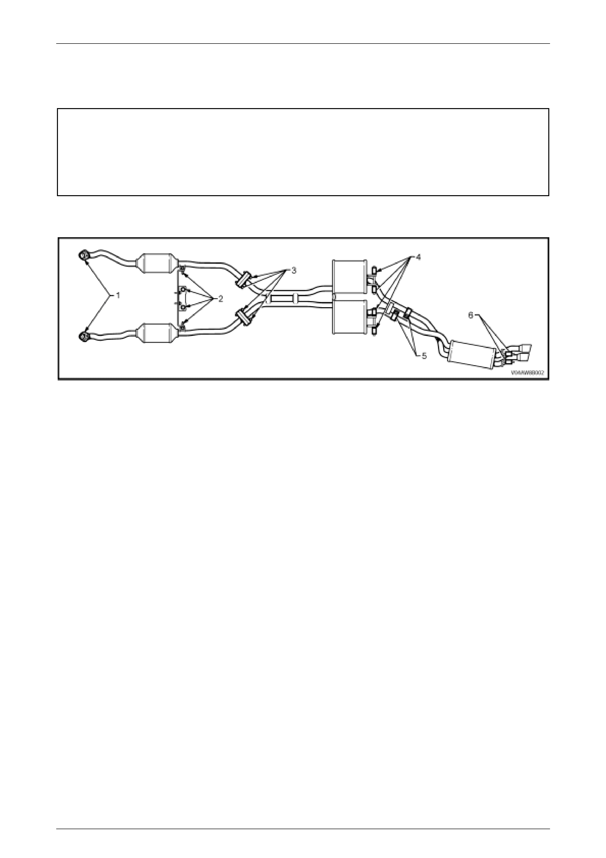
Figure 8B-2 shows the exhaust system layout as viewed from the top without the vehicle body.
Figure 8B-2
Installation
Loosely install exhaust system as follows;
1 Attach the front engine pipe and catalytic converter assembles, loosely to the exhaust manifolds (1).
2 Attach the exhaust hanger support bracket to the transmission adapter hous ing and loosely attach the front engine
pipe and catalytic converter assemblies to the exhaust hanger support bracket (2).
3 Hook the intermediate muffler assembly to suspension brackets with four bumper rubbers (two per intermediate
muffler) and fit the four retaining clips to the suspension bracket ends (4).
4 Hand start the bolts for the intermediate muffler to catalytic converter connecting flanges, after installing a new
gasket to each flange (3).
5 Install the intermediate muffler assembly to the rear muffler assembly and loosely install the two slip joint exhaust
pipe clamps (5).
6 Attach the rear muffler assembly to the body mount hangers with two bumper rubbers (6) and retaining clips.
Tightening Sequence
1 Tighten the bolts for the intermediate muffler to catalytic converter connecting flanges (3).
2 Evenly tighten the intermediate muffler assembly to rear muffler assembly slip joint exhaust pipe clamp nuts (5).
3 Evenly tighten each exhaust manifold to front engine pipe flange nut (two per flange), so that a similar amount of
thread is showing on each (1).
4 Ensure that all bumper rubbers are under load (4 and 6). If this is not achieved, loosen exhaust joints in the reverse
order to the above. Load the hangers and re-tighten in the sequence described, from steps 1 to 3.
5 After all other operations have been completed; tighten the exhaust hanger support bracket to the transmission
adapter housing and catalytic converter assembly to the exhaust hanger support bracket bolts (2).

Exhaust System Page 8B –5
Page 8B–5
NOTE:
The exhaust system should be self-aligning and
not require further adjustment, provided step 4 is
achieved.
Intermediate muffler assembly to
catalytic converter assembly flange
attaching bolt torque specification................40 – 50 Nm
Intermediate muffler assembly to rear
muffler assembly slip joint U-bolt clamp
attaching nut torque specification.................37 – 50 Nm
$ Exhaust manifold to front engine pipe
flange attaching nut torque specification.......18 –35 Nm
Exhaust hanger support bracket to
transmission adapter housing
attaching bolt torque specification................20 – 50 Nm
Catalytic converter assembly to
exhaust hanger support bracket
attaching bolt torque specification................20 – 50 Nm
Exhaust System Page 8B –6
Page 8B–6
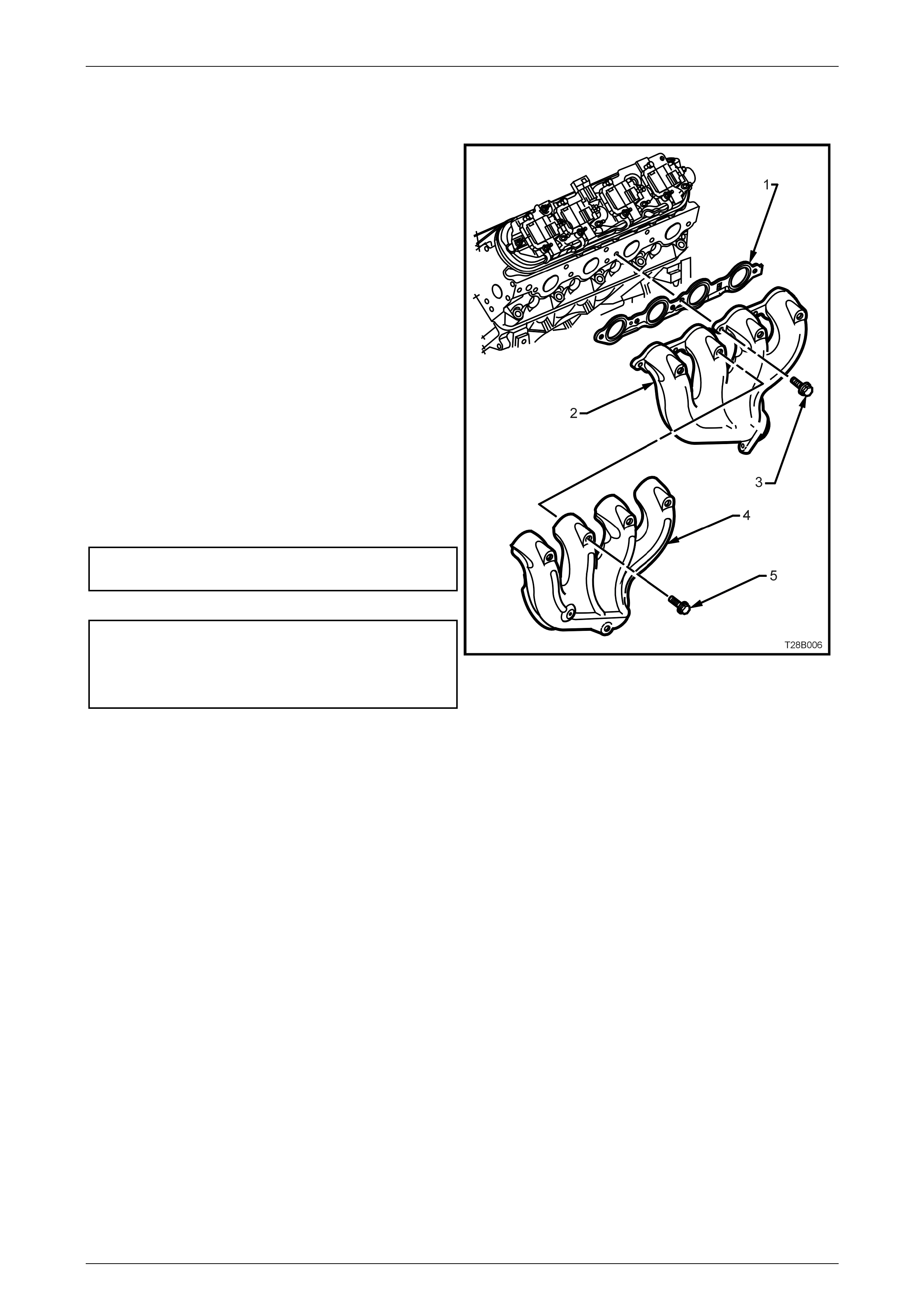
2.3 Exhaust Manifold Installation
The exhaust manifolds fitted to the GEN III V8 engine, are
of a one piece, high temperature silicone molybdenum cast
iron and direct exhaust gases from the combustion
chamber s to the ex haust syst e m.
Each manifold (2) also has an externally mounted, heat
shield (4) attached, which is made from aluminiumised
steel. Each heat shield is attached to the manifold by five
screws (5).
NOTE:
While the left hand exhaust manifold (2) is
shown, the right hand arrangement is similar.
Legend:
1 Gasket – Exhaust Manifold.
2 Manifold – Exhaust.
3 Bolt – Exhaust Manifold to Cyli nder Head.
4 Shield – Exhaust Manifold Heat.
5 Screw – Heat Shield to Exhaust Manifold (5 places).
Exhaust manifold heat shield
attaching bolt.................................................. 8 – 10 Nm
Exhaust man ifol d to cylin der head
attaching bolts torque specification.
Stage 1.................................................................15 Nm
Stage 2 ................................................................25 Nm
Figure 8B-3

Exhaust System Page 8B –7
Page 8B–7
2.4 Exhaust System Layout
Figure 8B-4
Legend
1 Bolt – Support Bracket to Catalytic Converter Assembly
Attaching (2 Places)
2 Bolt – Transmission Bracke t Attaching (2 Pl aces)
3 Support Bracket – Catal yt ic Convert er to Transmission
4 Bolt – Support Bracket to Transmission Bracket Attaching
(2 Places)
5 Nut – Engine Pipe to Exhaust Manifold Attaching (4 places)
6 Front Engine Pipe and Catalytic Converter Assembly.
7 Bolt – Front Engine Pipe and Catalytic Converte r As sembly
to Intermediat e Muffl er and Exhaust Pipe Assembly
(4 places)
8 Intermediate Muffler and Exhaust Pipe Assembly
9 Gasket – Front Engine Pipe and Catalytic Converter
Assembly to Intermediate Muffler and Exhaust Pipe
Assembl y (2 places)
Exhaust System Page 8B –8
Page 8B–8
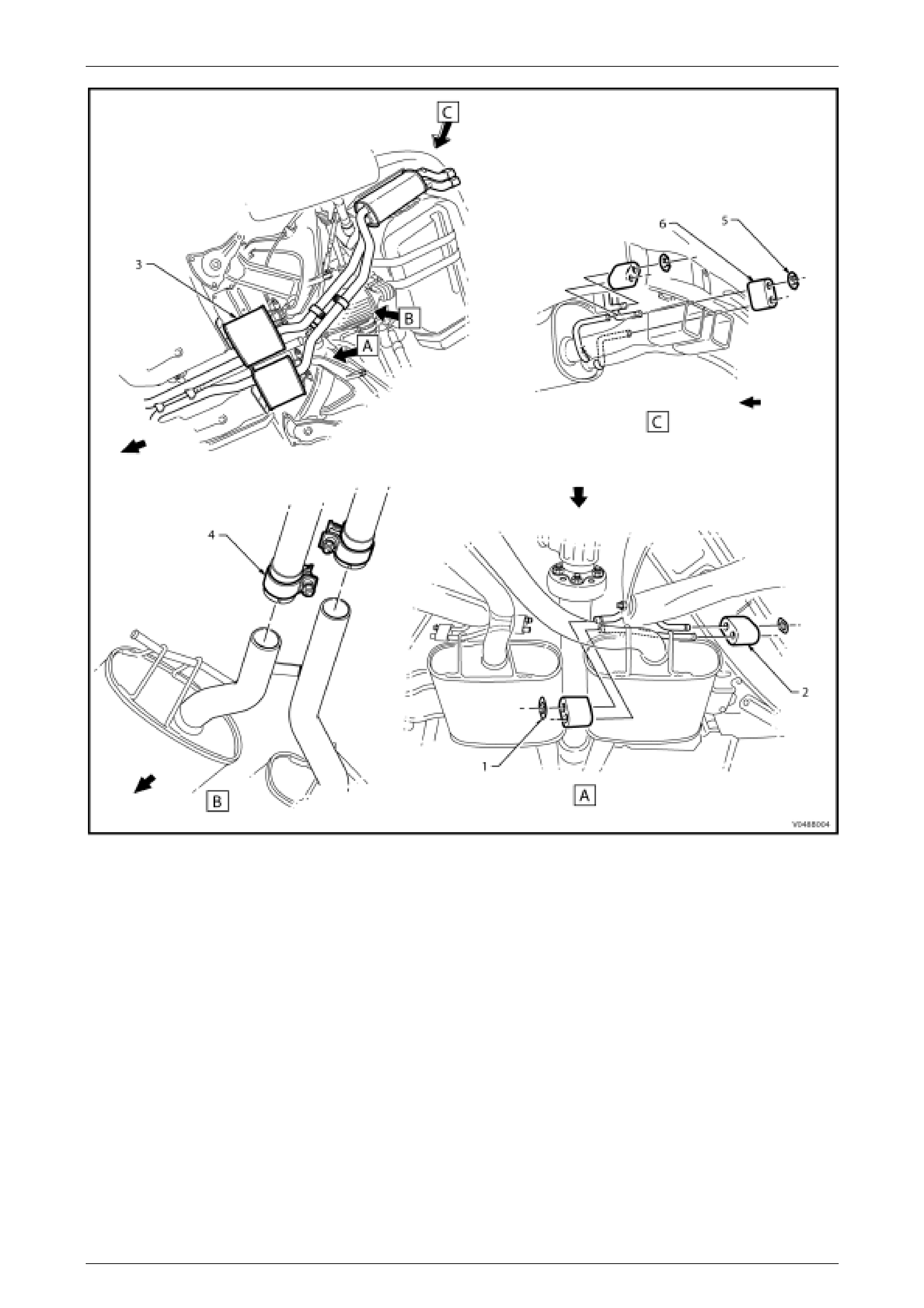
Figure 8B-5
Legend
1 Retainer – Bumper Rubber Intermediate Muf f l er (2 plac es)
2 Bumper Rubber – Intermedi ate Muffler and Exhaust Pipe
Assembl y (2 places)
3 Intermediate Muffler and Exhaust Pipe Assembly
4 Clamp – Intermediate Muffler and Exhaust P i pe Assembly to
Rear Exhaust Pipe and Muffler Assembly Attac hing (2
places)
5 Retainer – Bumper Rubber Rear Exhaust Pipe and Muffl er
Assembl y (2 places)
6 Bumper Rubber – Rear Exhaust Pipe and Muffler Ass embly
(2 places)
Exhaust System Page 8B –9
Page 8B–9
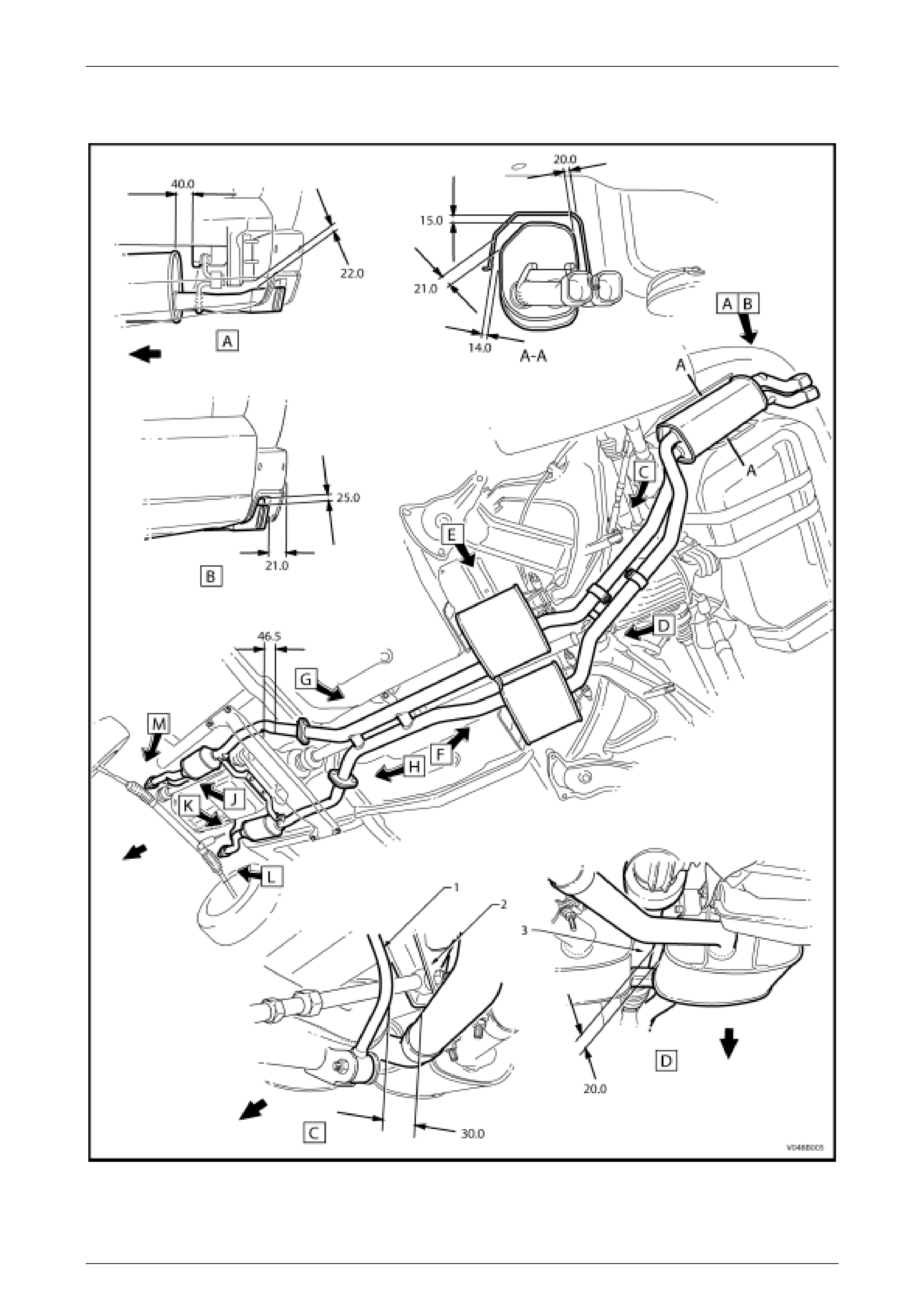
2.5 Exhaust System Clearances
Figure 8B-6
Legend
1 Rear Stabilis er Bar Link. 2 Rear Suspension Cont rol Arm
Mount 3 Rear Propeller Shaft

Exhaust System Page 8B –10
Page 8B–10
Figure 8B-7
Legend
1 Rear Footwell
2 Intermedi at e Heat Shiel d 3 RH Sub Frame
4 Engine Block
Exhaust System Page 8B –11
Page 8B–11
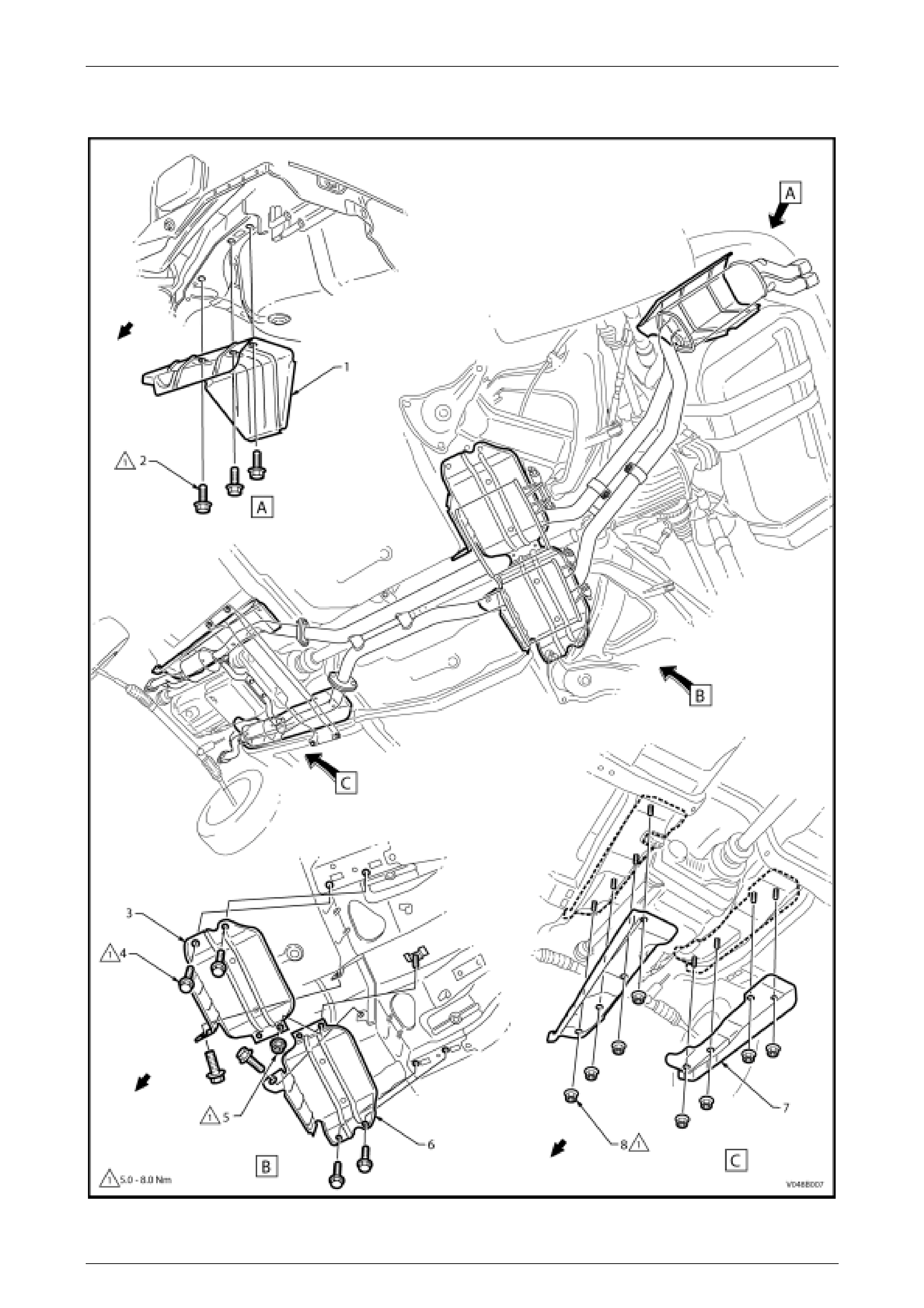
2.6 Exhaust System Heat Shields
Figure 8B-8

Exhaust System Page 8B –12
Page 8B–12
Legend
1 Heat Shiel d – Rear Muffler
2 Screw – Heat Shield Attaching (3 places)
3 Heat Shield – Intermedi ate Muffler – Left Hand
4 Screw – Heat Shield Attaching (6 places)
5 Nut – Heat Shield Attaching (2 places)
6 Heat Shiel d – Intermediate Muffler – Ri ght Hand
7 Heat Shield – Front Engine Pipe (2 places)
8 Nut – Heat Shield Attaching (8 places)

Exhaust System Page 8B –13
Page 8B–13
3 Exhaust System Di agnosis
CONDITION PROBABLE CAUSE CORRECTION
Leaking exhaust gases Leaks at pipe joints. Tighten U-bolt nuts and joint bolts to
the correct torque specifications.
Damaged or improperly installed
converter sealing ring/gaskets. Replace gasket as nec essar y.
Burned or rusted out exhaust pipe or
muffler/s. Replace component as necessary.
Exhaust noises Leaks at manifold or pipe connections. Tighten clamps at leaking
connect ion s to the corre ct torq ue
sp ecifications. Re place gask et as
required.
Burned or blown out pipe or muffler/s. Replace pipe/muffler assembly as
necessary.
Exhaust manifold/s cracked or broken. Replace manifold.
Leak between man ifol d/s and cy lind er
head/s. Tighten manifold to cylinder head
studs to the correct tor qu e
specification.
Loss of engine pow er, hesitat i on,
surging, poor fuel econo my , stalli ng
or
Clogged catalytic converter (may
result from serious engine
malfunction).
Replace catalytic converter.
hard starting Crushed pipework. Replace pipework.
Internal rattling in muffler Dislodged tubes and/or baffles in
muffler. Replace muffler.
Catalytic converter monolith has
crumbled and pieces blown into
muffler.
Replace catalytic converter
assembly and affected muffler.

Exhaust System Page 8B –14
Page 8B–14
4 Specifications
General
Exhaust System Type..........................................................................................Dual System
Engine Pipe Material..................................................................................409 Stainless Steel
Intermediate Muffler Assembly Material.....................................................409 Stainless Steel
Rear Muffler Assembly Material.................................................................409 Stainless Steel
Catalytic Converter
Make.................................................................................................................... AC Australia
Type......................................................................................................... Three Way Monolith
Outer Shell Material ..........................................................................................Stainless Steel
Inlet Diameter................................................................................................................ 57 mm
Outlet Diameter............................................................................................................. 57 mm
Volume............................................................................................................1.4 Litres (each)
Cells............................................................................................................................400 in%

Exhaust System Page 8B –15
Page 8B–15
5 Torque Wrench Specifications
ATTENTION
All exhaust system fasteners are important attaching parts as they affect the performance of vital
components and/or could result in major repair expense. Where specified in this Section, fasteners MUST be
replaced with parts of the same part number or a GM approved equivalent. Do not use fasteners of an inferior
quality or substitute design.
Torque values must be used as specified during reassembly to ensure proper retention of all steering
components.
Through out this Section, fastener torque wrench specifications may be accompanied with the following
Identification marks:
! Fasteners must be replaced after loosening.
"
""
" Vehicle must be at kerb height before final tightening.
#
##
# Fasteners either have micro encapsulated sealant applied or incorporate a mechanical thread lock and
should only be re-used once. If in doubt, replacement is recommended.
If one of these identification marks is present alongside a fastener torque wrench specification, the
recommendation regarding that fastener must be adhered to.
Nm
Intermediate Muffler Assembly to Catalytic Converter
Assembly Flange Attaching Bolt............................................................40 – 50
Intermediate Muffler Assembly to Rear Muffler Assembly
Slip Joint U-Bolt Clamp Attaching Nut....................................................37 – 50
# Exhaust Manifold to Front Engine Pipe Flange Attaching Nut.............18 – 35
Exhaust Hanger Support Bracket to Transmission Adapter
Housing Attaching Bolt...........................................................................20 – 50
Catalytic Converter Assembly to Exhaust Hanger Support
Bracket Attaching Bolt............................................................................20 – 50
Exhaust Manifold to Cylinder Head Attaching Bolts
Stage 1.................................................................................................15
Stage 2.................................................................................................25
Exhaust Manifold Heat Shield Attaching Screw.......................................8 – 10
Heat Shield Attaching Screws/Nuts To Underbody....................................5 – 8