
Steering Page 9–1
Page 9–1
Section 9
Steering
ATTENTION
Before performing any Service Operation or other procedure described in this Section, refer to Section 00
Cautions And Notes for correct workshop practices with regard to safety and/or property damage.
1 General Information............................................................................................................................... 2
2 Service Operations................................................................................................................................3
2.1 Power Steering gear...............................................................................................................................................3
Remove ...................................................................................................................................................................5
Reinstall ..................................................................................................................................................................5
2.3 Power Steering Fluid Cooler and Hose/Pipe Routing.........................................................................................6
Arrangement...........................................................................................................................................................6
3 Torque Wrench Specifications............................................................................................................. 9
Techline
Techline
Techline
Techline
Techline
Techline

Steering Page 9–2
Page 9–2
1 General Information
The power assisted steering system for MY2004 VY All Wheel Drive Wagon carries over from MY2004 VY & V2 Series
vehicles with the following exceptions.
• The steering gear pinion shaft is longer due to the unique new cross member design of the All Wheel Drive
Wagon, catering for the higher ground clearance and front drive train. The lower steering coupling to the
steering gear remains unchanged.
• The steering gear retains the VY steering gear specification, but utilises the roll imprinted Monaro control valve.
This control valve improves steering assist boost for parking speeds to offset the increase in front end weight.
• The location of the steering gear assembly mounting points are lower due to the unique new cross member
design of the All Wheel Drive Wagon, catering for the higher ground clearance and front drive train.
• New power steering oil pipes, hoses and cooler locations catering for the unique new cross member design of
the All Wheel Drive Wagon.
For information not contained within this Section, refer to Section 9, Steering in the MY2004 VY and V2 Series Service
Information.
NOTE
A driver’s inflatable restraint (airbag) is fitted as
standard equipment on all MY2004 VY & V2
Series vehicles. For detailed information
regarding the driver's airbag, including system
enable and disable procedures, refer to
Section 12M, Occupant Protection System in the
MY2004 VY & V2 Series Service Information.

Steering Page 9–3
Page 9–3
2 Service Operations
ATTENTION
All steering gear fasteners are important attaching parts as they affect the performance of vital components
and/or could result in major repair expense. Where specified in this Section, fasteners MUST be replaced with
parts of the same part number or a GM approved equivalent. Do not use fasteners of an inferior quality or
substitute design.
Torque values must be used as specified during reassembly to ensure proper retention of all steering
components.
Through out this Section, fastener torque wrench specifications may be accompanied with the following
Identification marks:
! Fasteners must be replaced after loosening.
"
""
" Vehicle must be at kerb height before final tightening.
#
##
# Fasteners either have micro encapsulated sealant applied or incorporate a mechanical thread lock and
should only be re-used once. If in doubt, replacement is recommended.
If one of these identification marks is present alongside a fastener torque wrench specification, the
recommendation regarding that fastener must be adhered to.
2.1 Power Steering gear
LT Section No. – 06-275
ATTENTION
The following fasteners have either micro encapsulation or incorporate a mechanical thread lock and should
only be used once. If in doubt, replacement is recommended when performing this operation:
#$ Steering gear pinion shaft to intermediate steering shaft coupling attaching nut.
The following fasteners MUST be replaced when performing this operation:
!
!!
! Steering gear to cross member attaching nut.
Steering Page 9–4
Page 9–4
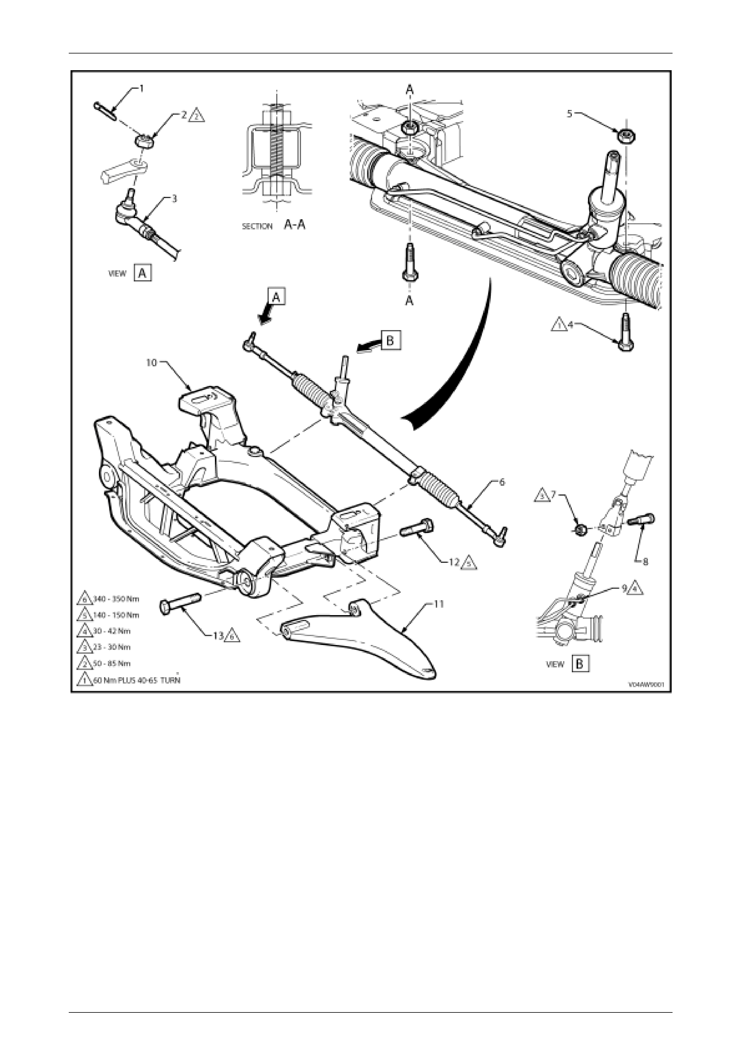
Figure 9-1Legend
1 Pin – Split, Tie Rod Socket Retaining Nut
2 Nut – Retaining, Tie Rod Socket to Steering Knuckle
3 Tie Rod Socket Assembly
4 Bolt – Attaching, Steering Gear to Cross Member
5 Nut – Attaching, Steering Gear to Cross Member
6 Steering Gear Assembly
7 Nut – Retaining, St eeri ng Coupling Cam Bolt
8 Cam Bolt – Attaching, Steering c oupling
9 Pipe – Fluid, Steering Gear
10 Cross Member Assembly
11 Control Arm – Lower
12 Bolt – Attaching, Lower Control Arm, Rear
13 Bolt – Att aching, Lower Control Arm, Front

Steering Page 9–5
Page 9–5
Remove
For removal procedure information not contained within this Section, refer to Section 9, Steering in the MY2004 VY and
V2 Series Service Information.
Reinstall
For reinstallation procedure information not contained within this Section, refer to Section 9, Steering in the MY2004 VY
and V2 Series Service Information.
For wheel alignment information refer to Section 3, Front Suspension in the MY2004 VY and V2 Series Service
Information.
! Steering gear to cross member
retaining nut torque specification.....................................
Stage 1.................................................................60 Nm
Stage 2............................................ 40º – 60º turn angle
% Steering coupling cam bolt
attaching nut torque specification.................23 – 30 Nm
Steering gear tie-rod lock
nut torque specification ................................ 40 – 60 Nm
Tie-rod socket attaching
nut torque specification ................................ 50 – 85 Nm
Steering gear fluid pipe flare nut
torque specification ...................................... 30 – 42 Nm

Steering Page 9–6
Page 9–6
2.3 Power Steering Fluid Cooler and
Hose/Pipe Routing
LT Section No. – 06-400
Arrangement
Refer to Figure 9-2 for the general layout of the power steering fluid cooler, pipes, hoses and fittings.

Steering Page 9–7
Page 9–7
Figure 9-2
Legend

Steering Page 9–8
Page 9–8
1 Steering Gear Assembly
2 O-ring – Power Steering Fluid Hose
3 Flare Nut – Power Steering Fluid Hose
4 Pipe and Hose Assembly – Steering Gear to Fluid Cooler
5 Pipe and Hose Assembly – Power Steering Pump to
Steering Gear
6 Clamp – Power Steering Fluid Reservoir Hose t o Pum p
7 Hose – Power Steering Fluid Reservoir to Pump
8 O-ring – Power Steering Pump Outlet Pipe
9 Flare Nut – Power Steering Pump Outlet Pipe
10 Hose – Power Steering Flui d Return to Reservoir, corpora
ting a restrict or at the reservoir end.
11 Bolt – Attaching, Return Pipe to Cross Member
12 Clamp – Power Steering Flui d Return Hose t o Return Pipe
13 Pipe – Power Steering Fluid Return
14 Bolt – Attaching, Return Pipe to Cross Member
15 Reservoir – Power Steering Fluid
16 Clamp – Power Steering Flui d Reservoir Out l et Hose to
Pump
17 Bolt – Attaching, Fluid Pipe Mounting Bracket t o Engine Oil
Pan

Steering Page 9–9
Page 9–9
3 Torque Wrench Specifications
ATTENTION
All exhaust system fasteners are important attaching parts as they affect the performance of vital
components and/or could result in major repair expense. Where specified in this Section, fasteners MUST be
replaced with parts of the same part number or a GM approved equivalent. Do not use fasteners of an inferior
quality or substitute design.
Torque values must be used as specified during reassembly to ensure proper retention of all steering
components.
Through out this Section, fastener torque wrench specifications may be accompanied with the following
Identification marks:
! Fasteners must be replaced after loosening.
"
""
" Vehicle must be at kerb height before final tightening.
#
##
# Fasteners either have micro encapsulated sealant applied or incorporate a mechanical thread lock and
should only be re-used once. If in doubt, replacement is recommended.
If one of these identification marks is present alongside a fastener torque wrench specification, the
recommendation regarding that fastener must be adhered to.
Nm
! Steering gear to cross member attaching nut................................................
Stage 1.................................................................................................60
Stage 2......................................................................40º – 60º turn angle
% Steering gear pinion shaft to intermediate steering shaft coupling
attaching nut..........................................................................................23 – 30
Steering gear tie-rod lock nut.................................................................40 – 60
Steering gear fluid pipe flare nut............................................................30 – 42
Flare Nut – Power Steering Fluid Hose..................................................30 – 42
Flare Nut – Power Steering Pump Outlet Pipe.......................................30 – 42
Clamp – Power Steering Fluid Reservoir Hose to Pump.....................2.0 – 3.0
Clamp – Power Steering Fluid Return Hose to Return Pipe ................2.0 – 3.0
Bolt – Attaching, Return Pipe to Cross Member ..................................5.5 – 7.5
Bolt – Attaching, Return Pipe to Cross Member ..................................5.5 – 7.5
Bolt – Attaching, Fluid Pipe Mounting Bracket to Engine Oil Pan..........20 – 30