Body Page 1A1–1
Page 1A1–1
Section 1A1
Body
ATTENTION
Before performing any Service Operation or other procedure described in this Section, refer to Section 00
Warnings, Cautions and Notes for correct workshop practices with regard to safety and/or property damage.
1 General Information............................................................................................................................... 2
2 Service Operations................................................................................................................................ 3
2.1 Plastic Components...............................................................................................................................................3
2.2 Rear Wheelhouse Liner .........................................................................................................................................6
Remove ...................................................................................................................................................................6
Reinstall..................................................................................................................................................................6
2.3 Inner Rear Body Panel...........................................................................................................................................7
Remove ...................................................................................................................................................................7
Reinstall..................................................................................................................................................................8
2.4 Rear Mudflap ..........................................................................................................................................................9
Remove ...................................................................................................................................................................9
Reinstallation..........................................................................................................................................................9
3 Torque Specifications ......................................................................................................................... 10

Body Page 1A1–2
Page 1A1–2
1 General Information
With the following exceptions, MY 2004 VY Regular Cab and Crew Cab Body information carries over from MY 2004 VY
Series vehicles and MY 2003 VY Regular Cab vehicles.
Crew Cab:
• Plastic components
• Rear wheelhouse liner
• Inner rear body panel
• Rear mudflap
For information not contained within this Section, refer to Section 1A1 Body in the MY 2004 VY and V2 Series Service
Information and Section 1A1 Body in the MY 2003 VY Regular Cab Service Information.
Body Page 1A1–3
Page 1A1–3
2 Service Operations
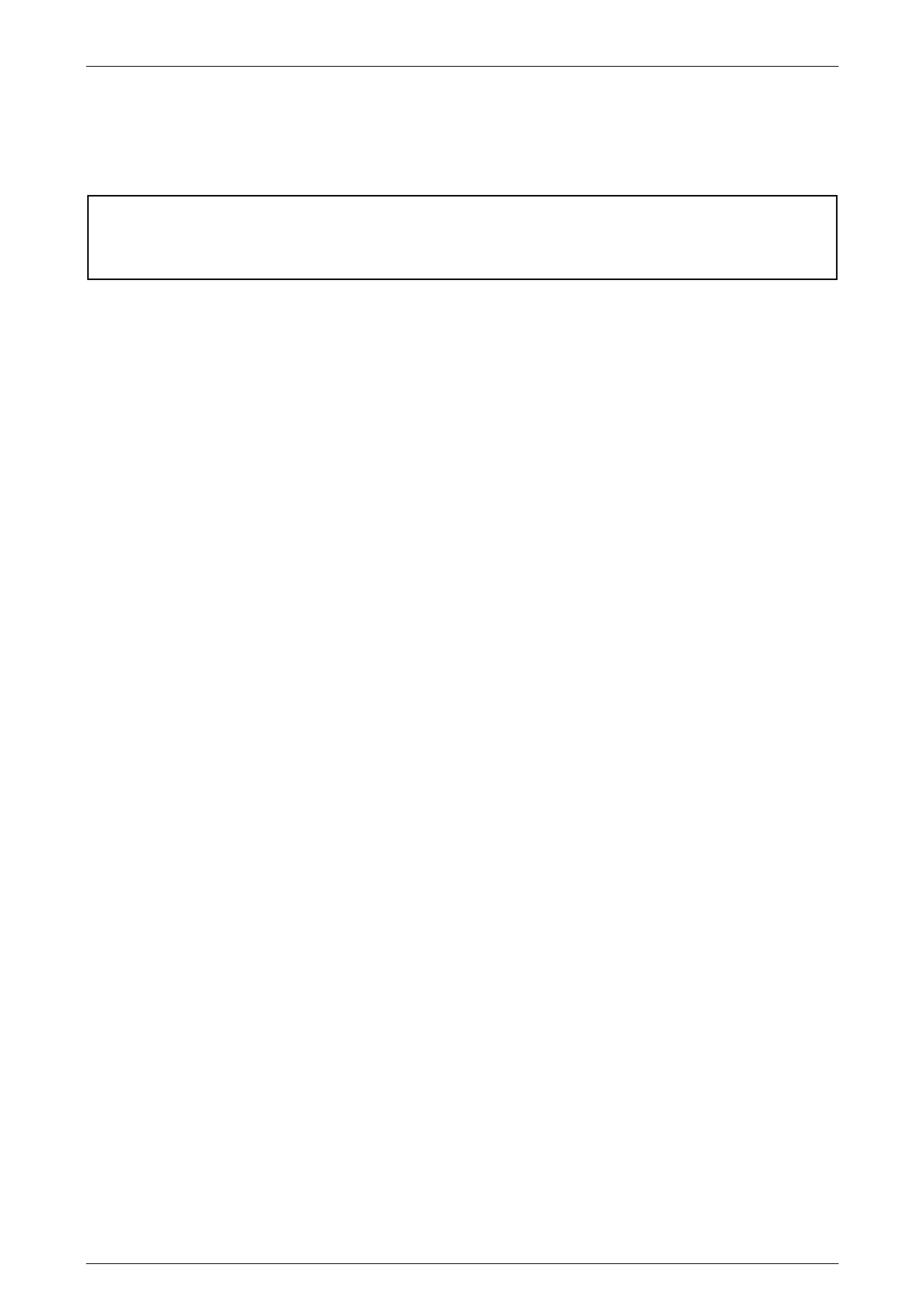
2.1 Plastic Components
NOTE
Most components are also identified with the
material code in an inconspicuous place.
Rear Wheelhouse Liner
Material: PP
Rear Body Rear Rocker Moulding
Material: Mineral Filled PP
Body Lock Pillar Trim Retainer Moulding
Material: Mineral Filled PP
Body Page 1A1–4
Page 1A1–4
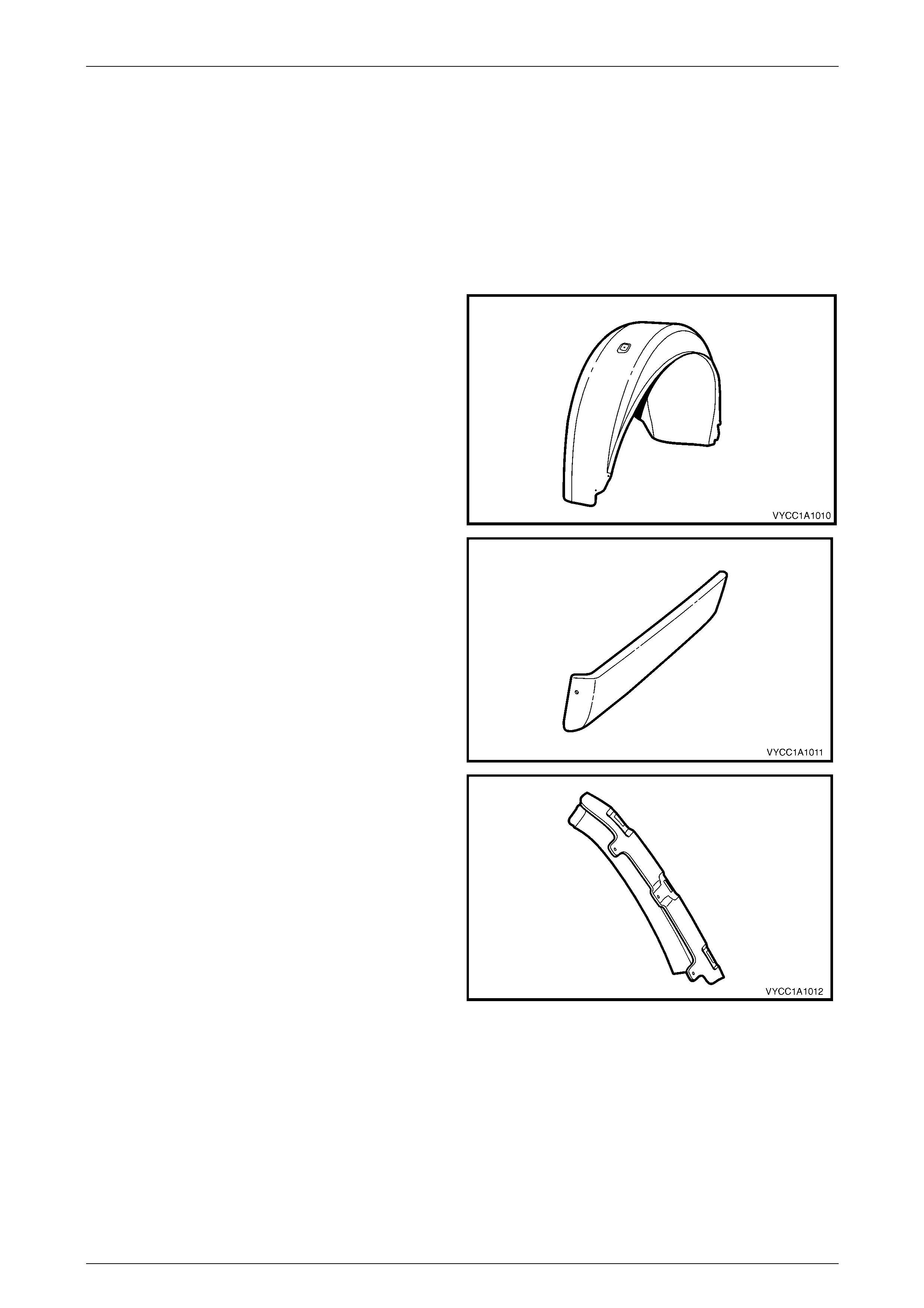
Rear Body Front Rocker Moulding
Material: PP
Rear Window Lower Finisher
Material: ABS / PC
Inner Rear Body Panel
Material:
10% GF Recycled PP
Rear Header Trim Assembly
Material: ABS / PC
Body Page 1A1–5
Page 1A1–5
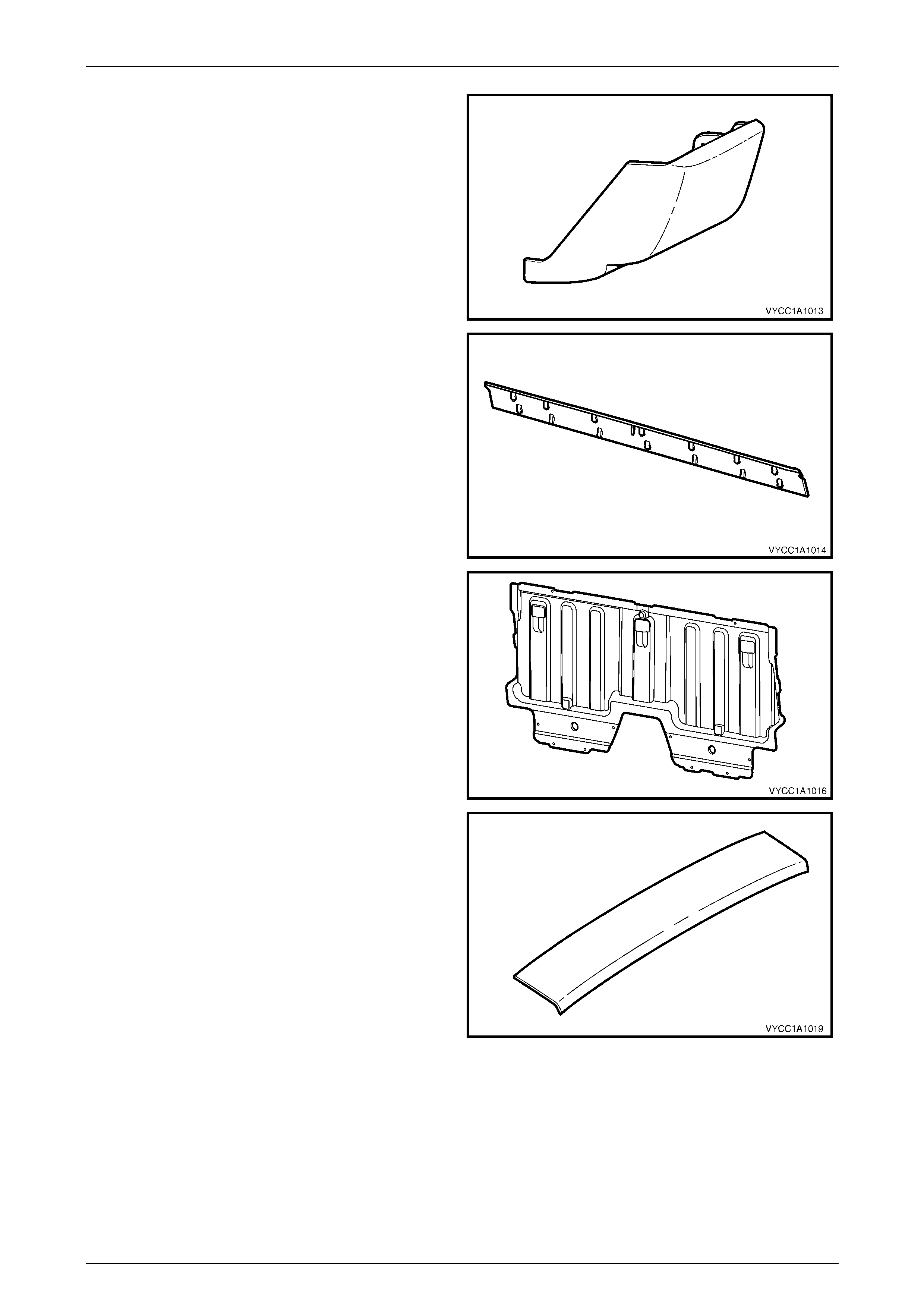
Body Lock Pillar Trim
Material: ABS / PC
Rear Body Front Rail Cover
Material: Mineral Filled PP
Body Lock Pillar Door Finisher
Material: ABS / PC
Rear Mudflap
Material: PP
Body Page 1A1–6
Page 1A1–6
2.2 Rear Wheelhouse Liner
Remove
1 Remove the rear road wheel, refer to Section 10, Wheels & Tyres in the MY 2004 VY and V2 Series Service
Information.
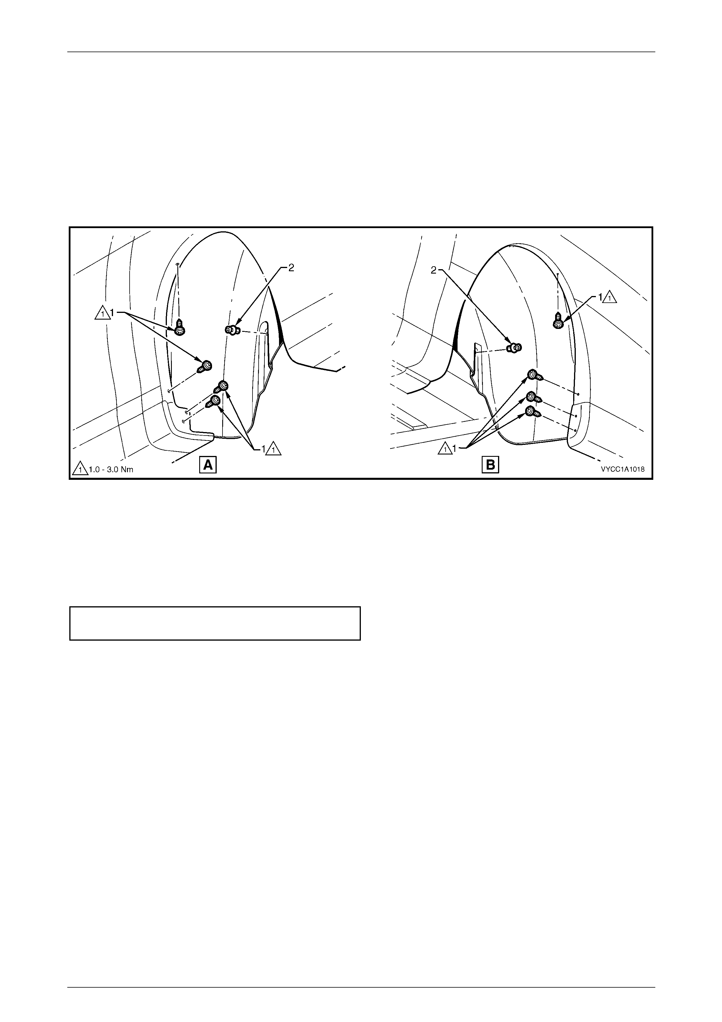
2 Remove the eight screws (1), attaching the rear wheelhouse liner to the body, refer to Figure 1A1–1.
3 Remove the two fasteners (2), attaching the rear wheelhouse liner to the body.
Figure 1A1 – 1
4 From the rear of the vehicle, gently pull the liner down and remove.
Reinstall
1 Reinstallation of the rear wheelhouse liner is the reverse of the removal procedure ensuring all fasteners are
attached correctly and all screws are tightened to the specified torque.
Rear wheelhouse liner attaching screw
torque specification....................................1.0 – 3.0 Nm
Body Page 1A1–7
Page 1A1–7
2.3 Inner Rear Body Panel
Remove
As required, remove the following:
1 Remove the rear seat-back assembly, refer to Section 1A7, 4.4 Rear Seat-back Assembly.
2 Remove the upper cross beam cover, refer to Section 1A8, 3.5 Upper Cross-beam Cover.
3 Remove the child seat restraint and seatbelts, refer to Section 12M Occupant Protection System.
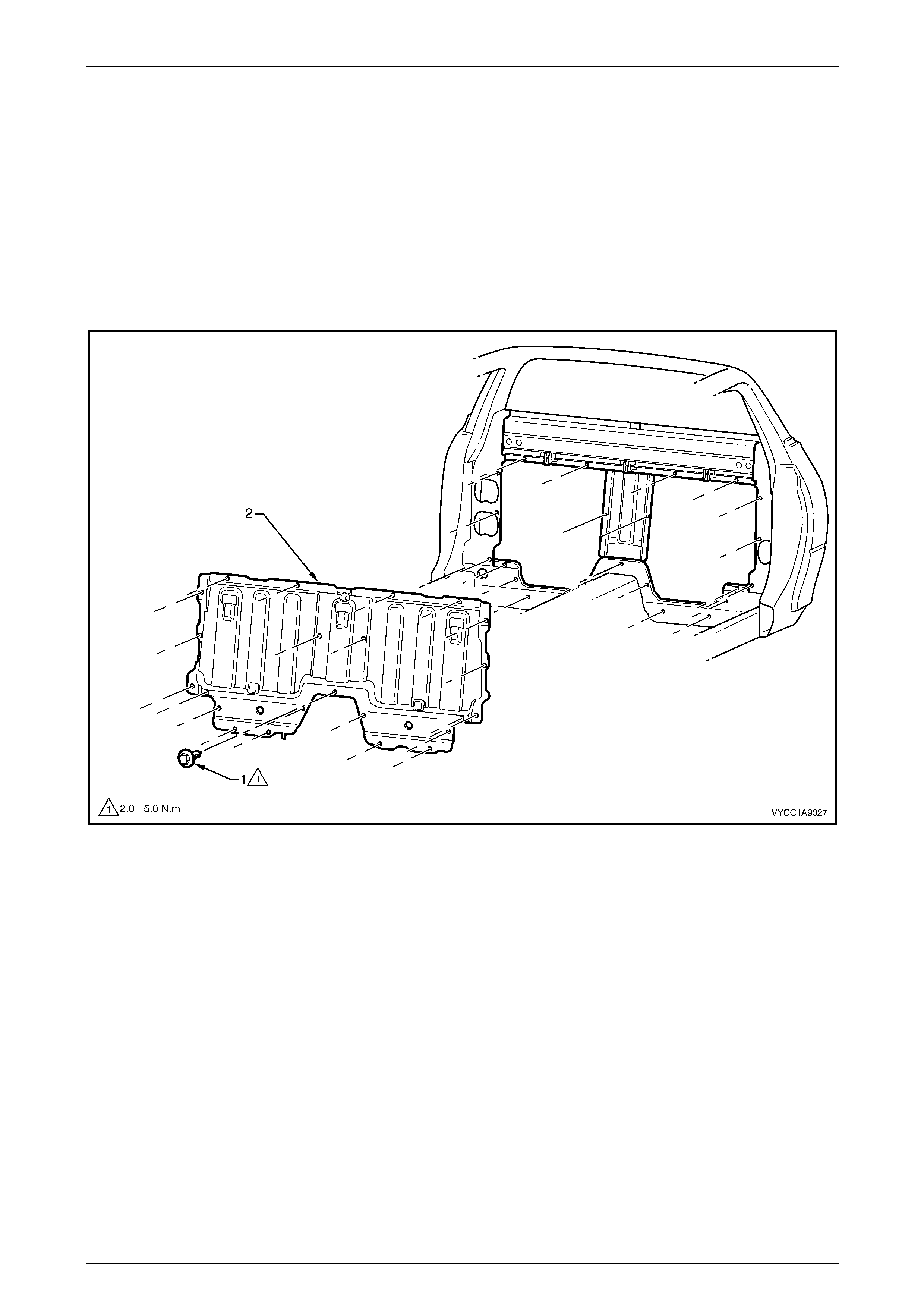
4 Remove the 23 screws (1), attaching the inner rear body panel (2), to the body, refer to Figure 1A1 – 2.
Figure 1A1 – 2
5 Using a suitable screwdriver, gently lever the inner rear body panel forward to loosen the sealer and remove the
panel through the rear door.
NOTE
If the noise reduction foam has not been
removed use care not to dislodge the foam
where it is glued to the rear panel support in the
two places, refer to Section 1A9, 4.10 Rear Outer
Trim Panel and NVH Foam.
Body Page 1A1–8
Page 1A1–8
Reinstall
1 Clean off any residual sealer from the surfaces of the inner rear body panel and body.
2 Ensure the NVH foam is fitted in the correct location, refer to Section 1A9, 4.10 Rear Outer Trim Panel and
NVH Foam.
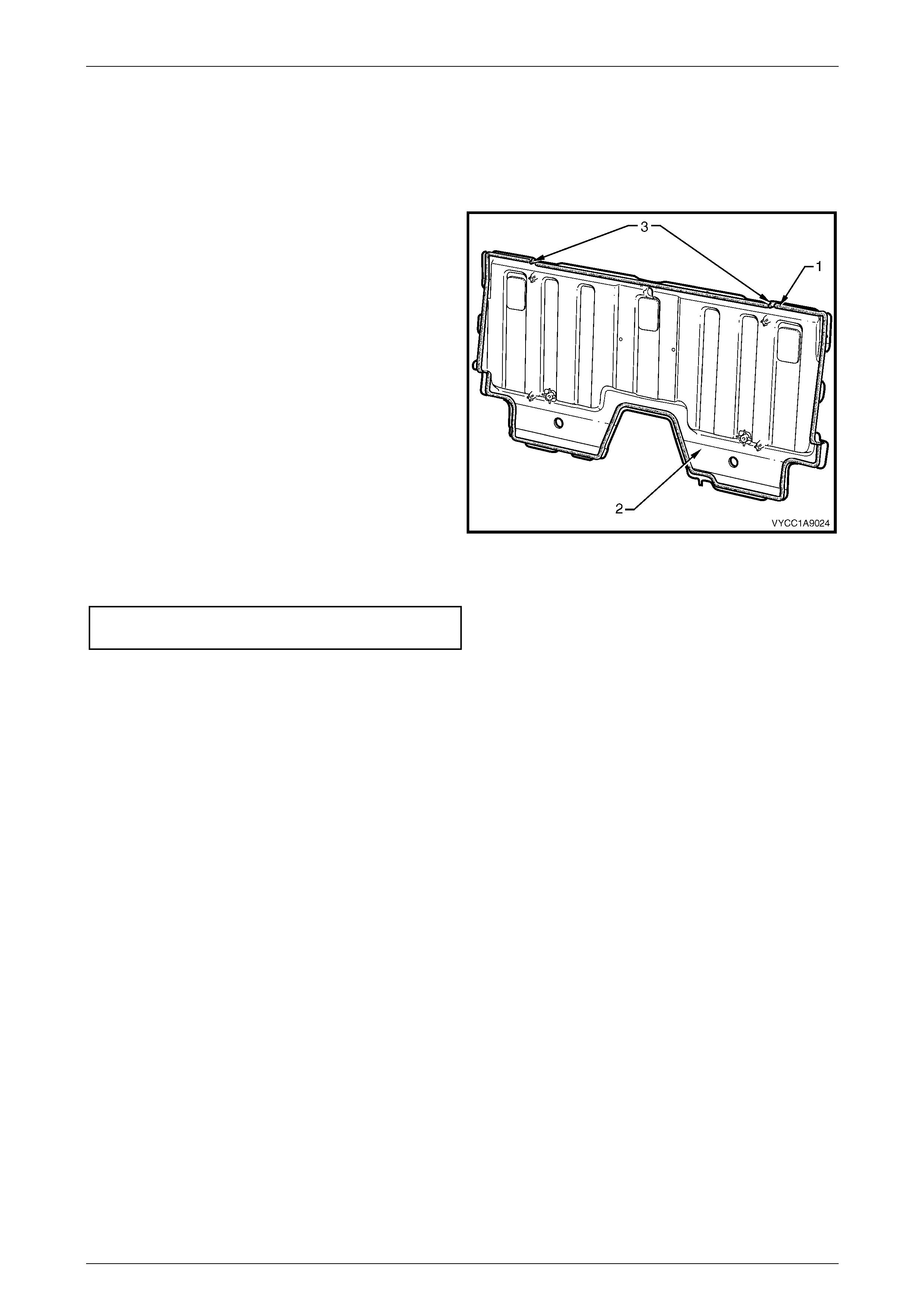
3 Apply a bead of mastic sealer (1), mastic or similar
around the edges of the inner rear body panel (2).
4 Using the data pins (3) on the inner rear body panel,
align the panel to the body.
Figure 1A7 – 3
5 Reinstall the 23 screws attaching the inner rear body panel and tighten to the specified torque.
Inner rear body panel attaching screw
torque specification....................................2.0 – 5.0 Nm
6 Reinstall the upper cross beam cover, refer to Section 1A8, 3.5 Upper Cross Beam Cover.
7 Reinstall the child seat restraint and seatbelts, refer to Section 12M, Supplementary Restraint System.
8 Reinstall the rear seat-back assembly, refer to Section 1A7, 4.4 Rear Seat-back Assembly.
Body Page 1A1–9
Page 1A1–9
2.4 Rear Mudflap
Remove
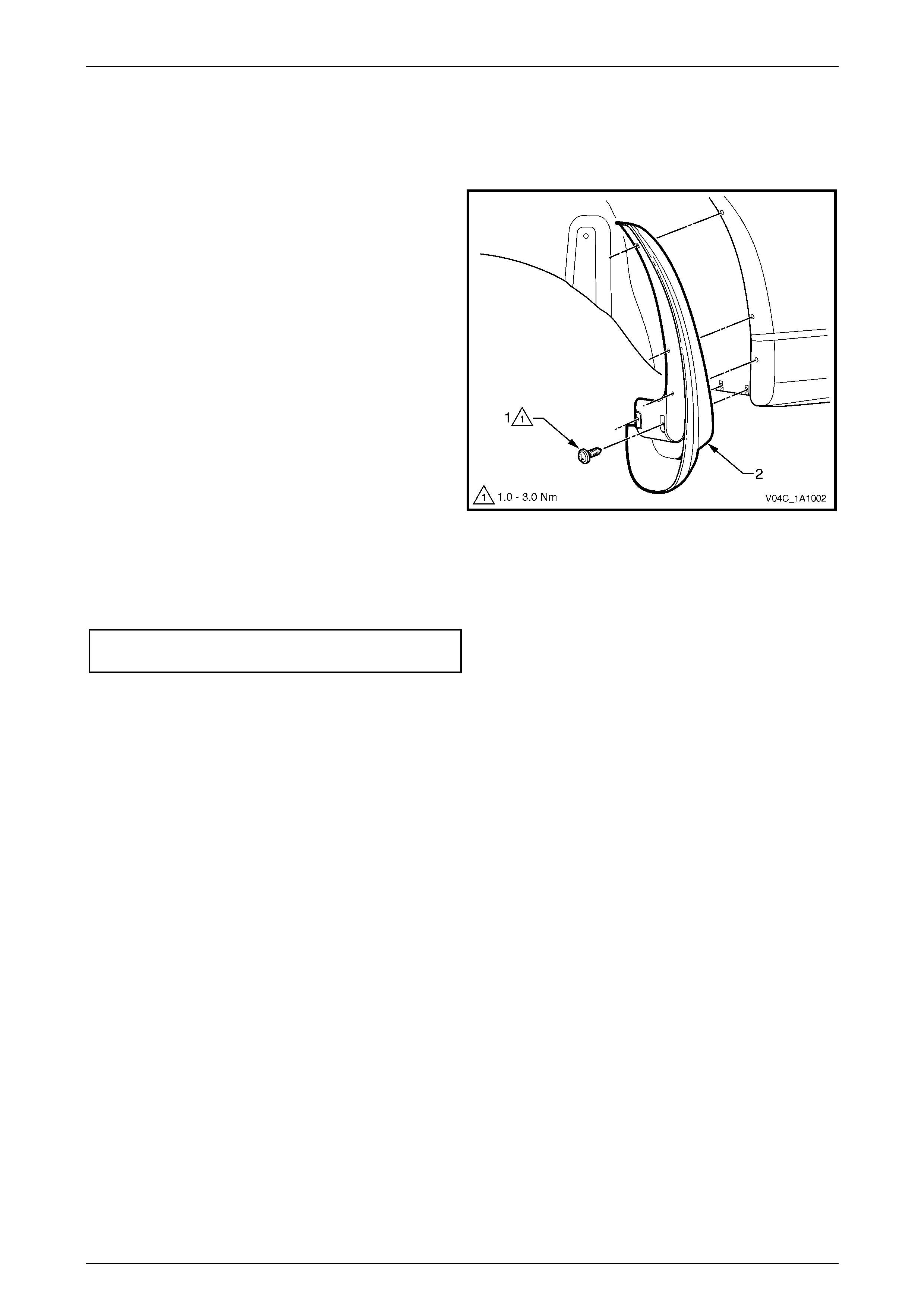
1 Remove the screw (1), five places attaching the rear
mudflap (2) to the rear body and remove the mudflap.
Figure 1A1 – 4
Reinstallation
Reinstallation of the rear mudflap is the reverse of the removal procedure. Tighten the screws to the specified torque.
Rear mudflap attaching screw
torque specification....................................1.0 – 3.0 Nm

Body Page 1A1–10
Page 1A1–10
3 Torque Specifications
Rear Wheelhouse Liner Attaching Screw......................................1.0 – 3.0 Nm
Inner Rear Body Panel Attaching Screw .......................................2.0 – 5.0 Nm
Rear Mudflap Attaching Screw......................................................1.0 – 3.0 Nm