
Body Dimensi ons Page 1A2–1
Page 1A2–1
Section 1A2
Body Dimensions
ATTENTION
Before performing any Service Operation or other procedure described in this Section, refer to Section 00
Warnings, Cautions and Notes for correct workshop practices with regard to safety and/or property damage.
1 General Information............................................................................................................................... 2
2 Service Operations................................................................................................................................3
2.1 Upper Body Dimensions Projected ......................................................................................................................3
Measuring Points ...................................................................................................................................................4
Underbody ..............................................................................................................................................................5
2.2 Upperbody Dimensions – Actual..........................................................................................................................6
Front........................................................................................................................................................................6
Side and Interior.....................................................................................................................................................7
Rear Body ...............................................................................................................................................................8

Body Dimensi ons Page 1A2–2
Page 1A2–2
1 General Information
With the following exceptions, MY 2004 VY Regular Cab and Crew Cab Body Dimensions information carries over from
MY 2004 VY Series vehicles and MY 2003 VY Regular Cab vehicles.
• Crew Cab Body Dimensions
For information not contained within this Section, refer to Section 1A2 Body Dimensions in the MY 2004 VY and V2
Series Service Information and Section 1A2 Body Dimensions in the MY 2003 VY Regular Cab Service Information.
Correct alignment of the body structure is essential to ensure the vehicle performs as intended. A body structure that is
outside design tolerances can suffer difficult operation and poor fitment of the doors, hood or endgate. Suspension
performance and vehicle handling can also suffer and noise, vibration and harshness may become evident.
The body structure should therefore be aligned to within ± 1.5 mm of the dimensions specified in this Section.
As a minimum, these dimensions should be accurately checked with a trammel gauge consisting of a parallel bar or rod
fitted with two adjustable trammels.
In preparation for an underbody alignment check, the vehicle must be correctly set-up on a level surface, preferably
using a measuring or jigging system specifically designed for the task of checking and correcting vehicle body alignment.
Note that the dimensions provided for the underbody are projected: the measuring points are transposed onto a two
dimensiona l (flat) surfa ce and the meas ure ment s are taken along the one plane.
All upperbody measurements are actual: the distance from point to point.
Incorrect alignment of the front suspension frame and transmission support can have an adverse affect on the vehicle’s
performance and introduce noise, vibration and harshness. Whenever they are replaced they must be aligned correctly,
refer to Section 1A2 Body Dimensions in the MY 2004 VY and V2 Series Service Information.

Body Dimensi ons Page 1A2–3
Page 1A2–3
2 Service Operations
2.1 Upper Body Dimensions Projected
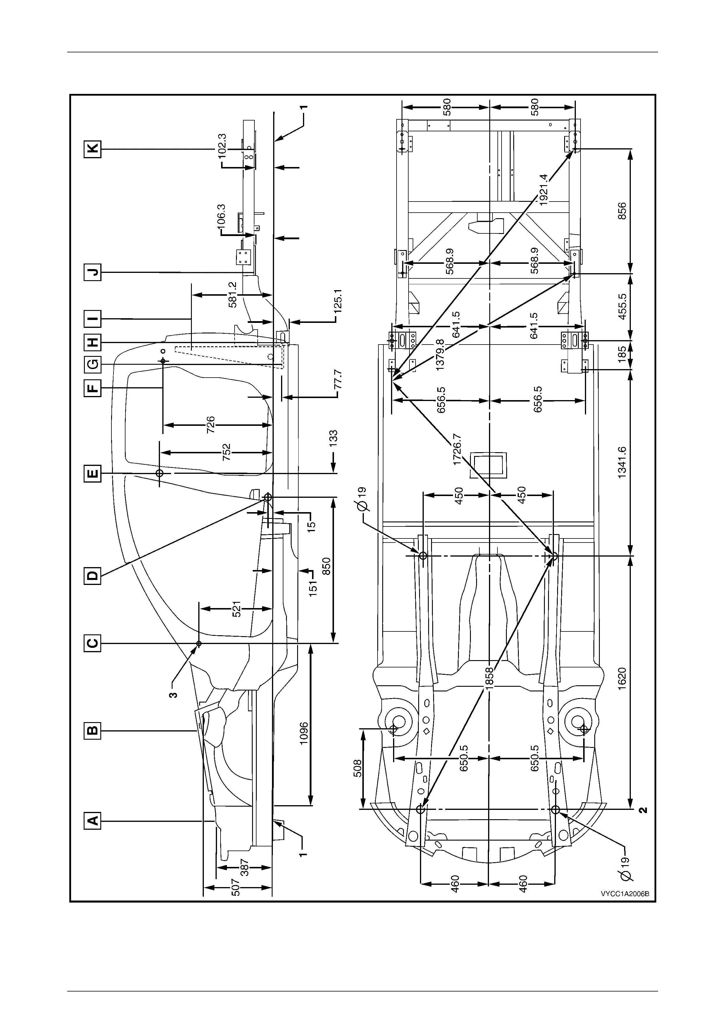
All dimensions are given in millimetres and are measured from the centre of holes, on the outer side of the metal surface.
The main datum surface (1) is the underside of the front side rail assembly, refer to Figure 1A2 – 2.
The main datum hole (2) is a 19 mm hole on the underside of the front side rail assembly, refer to Figure 1A2 – 2.
The dash panel assembly attaching hole (3) in Figure 1A2 – 2 is also the same datum hole depicted at View C, in
Figure 1A2 – 1.
Body Dimensi ons Page 1A2–4
Page 1A2–4
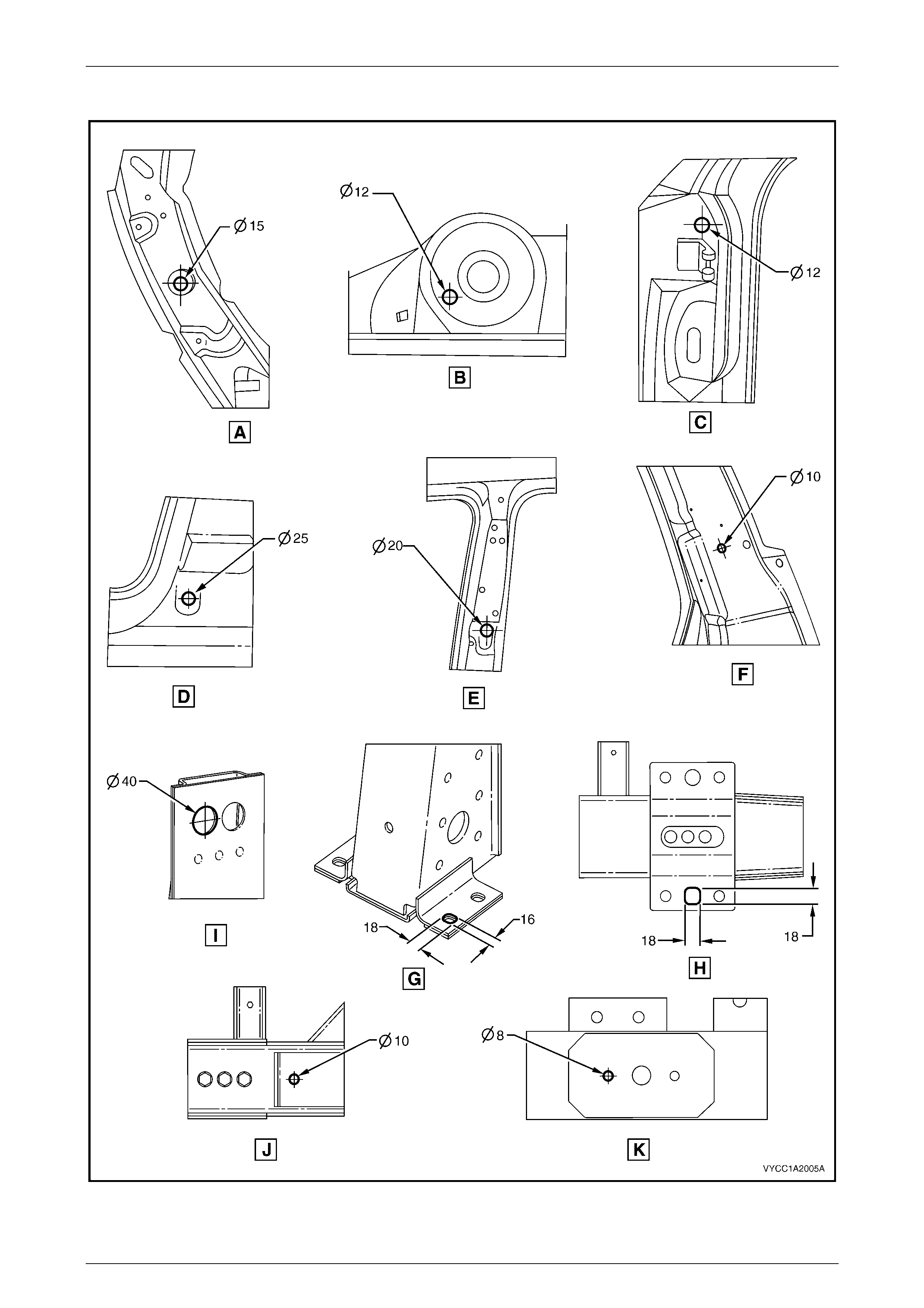
Measuring Points
Figure 1A2 – 1
Body Dimensi ons Page 1A2–5
Page 1A2–5
Underbody
Figure 1A2 – 2
Body Dimensi ons Page 1A2–6
Page 1A2–6
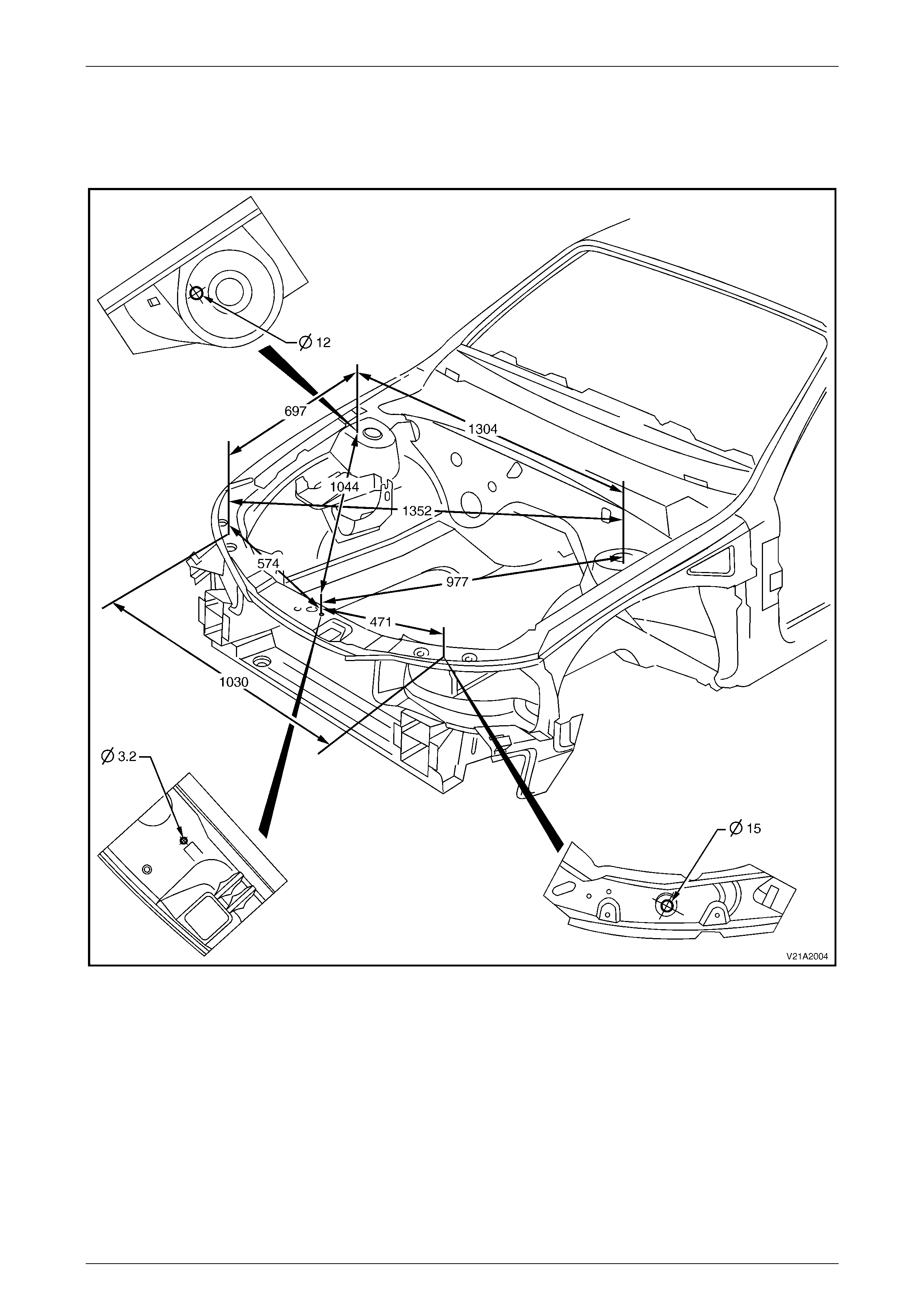
2.2 Upperbody Dimensions – Actual
Front
Figure 1A2 – 3
Body Dimensi ons Page 1A2–7
Page 1A2–7
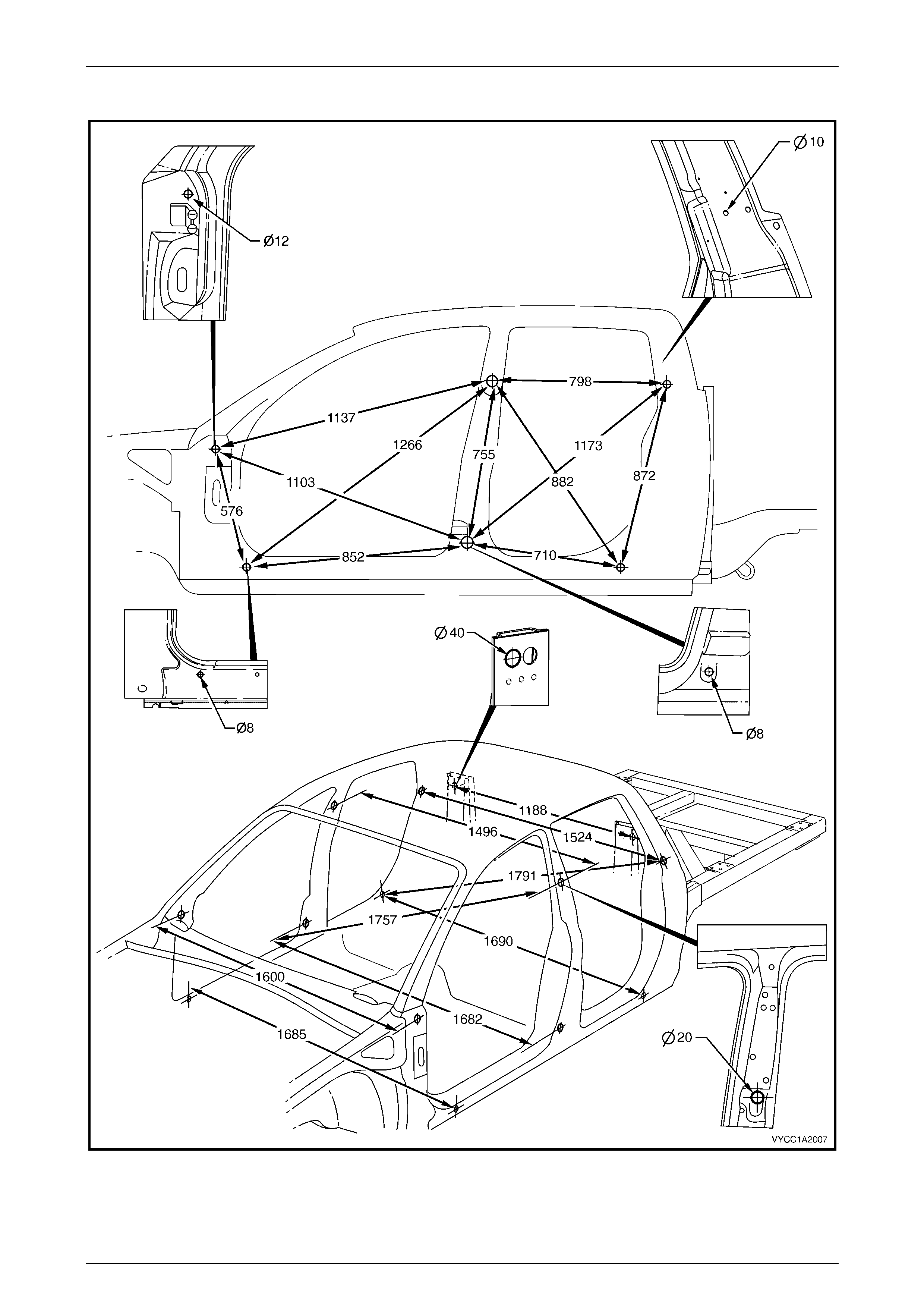
Side and Interior
Figure 1A2 – 4
Body Dimensi ons Page 1A2–8
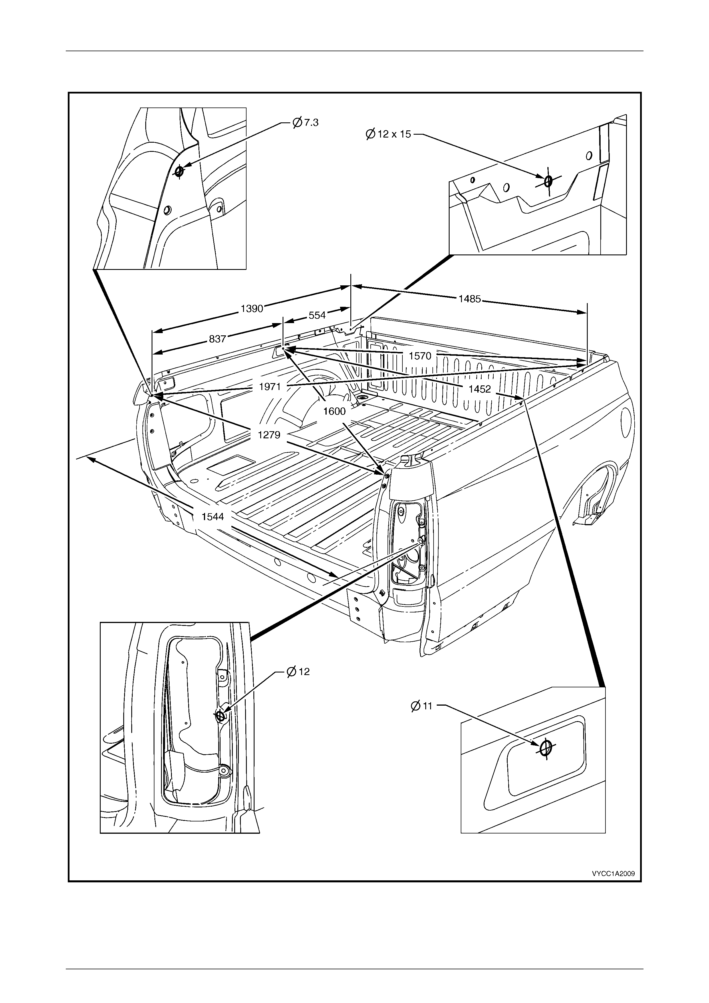
Page 1A2–8
Rear Body
Figure 1A2 – 5