
Front and Rear Door Assemblies Page 1A5–1
Page 1A5–1
Section 1A5
Front and Rear Door Assemblies
ATTENTION
Before performing any service operation or other procedure described in this Section, refer to Section 00
Warnings, Cautions and Notes for correct workshop practices with regard to safety and/or property damage.
1 General Information............................................................................................................................... 2
1.1 General Description...............................................................................................................................................2
2 Service Operations – Rear Doors......................................................................................................... 3
2.1 Rear Door Trim Panel Assembly...........................................................................................................................3
Remove ...................................................................................................................................................................3
Disassemble ...........................................................................................................................................................4
Rear Door Power Window Switch.......................................................................................................................5
Rear Door Armrest Insert Assembly...................................................................................................................5
Rear Door Pull Cup.............................................................................................................................................6
Rear Door Radio Speaker Grille.........................................................................................................................6
Rear Door W indow Inner Sealing Strip...............................................................................................................6
Reinstall ..................................................................................................................................................................7
2.2 Rear Door Lock Assembly.....................................................................................................................................8
Remove ...................................................................................................................................................................8
Disassemble ...........................................................................................................................................................9
Reassemble ............................................................................................................................................................9
Reinstall ..................................................................................................................................................................9
2.3 Rear Door Window Channel Assembly..............................................................................................................10
Remove .................................................................................................................................................................10
Reinstall ................................................................................................................................................................12
3 Torque Wrench Specifications........................................................................................................... 13
Techline
Techline
Techline
Techline
Techline
Techline

Front and Rear Door Assemblies Page 1A5–2
Page 1A5–2
1 General Information
With the following exceptions, MY 2004 VY Regular Cab and Crew Cab Front and Rear Door Assemblies carries over
from MY 2004 VY and V2 Series vehicles and MY 2003 VY Regular Cab vehicles.
Crew Cab
• Rear doors
For Front and Rear Door Assemblies information not contained in this section, refer to Section 1A5 Front and Rear Door
Assemblies in the MY 2004 VY and V2 Series Service Information and Section 1A5 Front and Rear Door Assemblies in
the MY 2003 VY Regular Cab Service Information.
1.1 General Description
The rear door assemblies fitted to the Crew Cab are unique, however, they are similar to the rear door assemblies fitted
to the Sedan and Wagon. Differences in the Crew Cab rear doors as compared to Sedan and Wagon include:
• Rear door assembly
• Rear door trim panel assembly
• Rear door armrest insert assembly
• Rear door pull cup
• Rear door pull cup bracket
• Rear door seal
• Rear door locking rods
• Rear door power window switch location
• Rear door window channel assembly
• Rear door window inner sealing strip
Front and Rear Door Assemblies Page 1A5–3
Page 1A5–3
2 Service Operations – Rear Doors
2.1 Rear Door Trim Panel Assembly
LT Section – 14-270
Remove
The orange rear door locking rod knob
retainer will be damaged during this operation
and must be replaced.
1 Remove the rear window regulator handle assembly (if fitted), refer to Section 1A5 Front and Rear Door Assemblies
in the MY 2004 VY and V2 Series Service Information.
2 Remove the door inside handle assembly, refer to Section 1A5 Front and Rear Door Assemblies in the MY 2004
VY and V2 Series Service Information.
Take care not to damage the rear door
locking rod knob assembly.
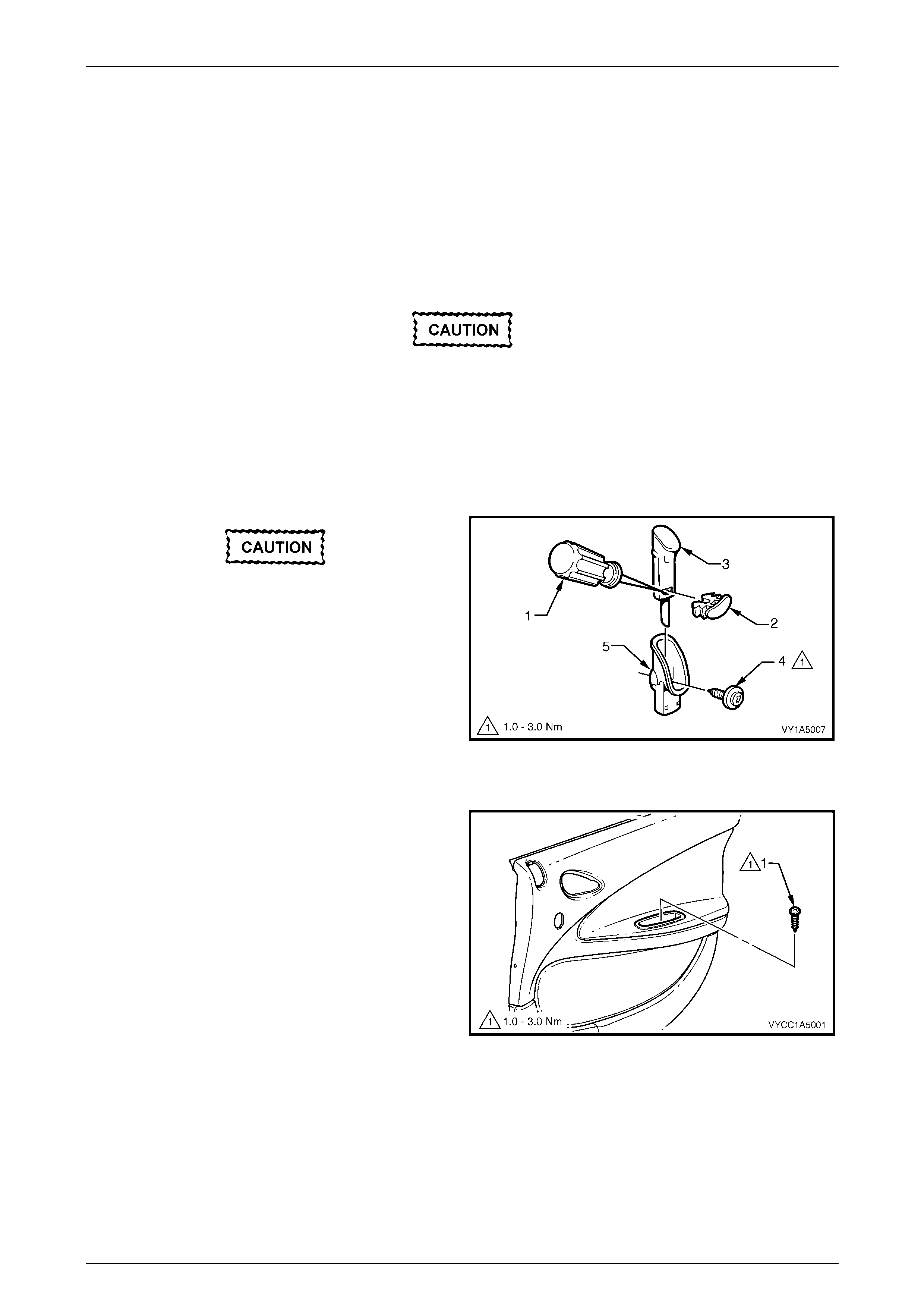
3 Using a small flat bladed screwdriver or scriber (1),
gently prise the orange rear door locking rod knob
retainer (2) from the rear door locking rod knob
assembly (3).
4 Remove the rear door locking rod knob assembly from
the rear door locking rod.
5 Remove the screw (4) attaching the rear door locking
rod ferrule (5) to the rear door trim panel assembly
and remove the rear door locking rod ferrule.
Figure 1A5 – 1
6 Remove the screw (1) from the rear door pull cup.
Figure 1A5 – 2
Front and Rear Door Assemblies Page 1A5–4
Page 1A5–4
7 Remove the screws (1), in six places, attaching the
rear door trim panel assembly to the rear door
assembly.
8 Lift the rear door trip panel assembly upwards to
release it from the rear door inner channel and remove
the rear door trim panel assembly from the rear door
assembly.
NOTE
The wiring harness connectors will still be
connected.
9 Support the rear door trim panel assembly and
disconnect the rear door wiring harness connectors.
10 Remove the rear door trim panel assembly.
Figure 1A5 – 3
Disassemble
Figure 1A5 – 4
Legend
1 Rear Door Pull Cup
2 Rear Door Armrest Ins ert Assembly
3 Rear Door Armrest Ins ert Assembly Clip (2 Places)
4 Rear Door Power Window Switch (If Fitted)
5 Rear Door Radio Grille Speaker
6 Rear Door Trim Panel Assembly
7 Radio Rear Door Speaker Grille Retainer (7 Places)
8 Rear Door Insulator Assembly
9 Rear Door Armrest Ins ert Assembly Nut (4 Places)
10 Rear Door W i ndow Inner Sealing Stri p

Front and Rear Door Assemblies Page 1A5–5
Page 1A5–5
Rear Door Power Window Switch
Remove
1 From behind the rear door trim panel assembly, press
the tangs and remove the rear door power window
switch (1).
NOTE
For further information regarding service and
diagnosis of the rear door power window switch,
refer to Section 12J Body Control Module in the
MY 2004 VY and V2 Series Service Information.
Reinstall
1 Ensuring that the rear door power window switch
connector points upwards, press the rear door power
window switch into the rear door trim panel assembly.
Figure 1A5 – 5
Rear Door Armrest Inse rt Assemb l y
Remove
1 To allow access to the rear door armrest insert assembly attaching parts, peel back the rear door insulator
assembly from the upper portion of the rear door trim panel assembly, refer to Section 1A5 Front and Rear Door
Assemblies in the MY 2004 VY and V2 Series Service Information.
2 Remove the clips (1), in two places, by sliding them
away from the rear door trim panel assembly (2).
When removing the insert assembly door
armrest nuts, a rotating action may cut off
the shaft. If a shaft is cut off, replace the rear
door insert assembly.
3 Remove the rear door armrest insert assembly
nuts (3), in four places, attaching the rear door armrest
insert assembly (4) to the rear door trim panel
assembly.
4 Prise the rear door armrest insert assembly away from
the rear door trim panel assembly. Slide the rear door
armrest insert assembly towards the rear of the rear
door trim panel assembly and remove.
Reinstall
Reinstallation of the rear door armrest insert assembly is the
reverse of the removal procedure, noting the following:
1 Check that the rear door armrest insert assembly sits
flush against the entire length of the top contacting
surface of the rear door trim panel assembly.
2 Tighten the nuts to the specified torque.
Rear door armrest insert assembly nut
torque specific atio n .................................... 0.7 – 0.9 Nm
Figure 1A5 – 6
Front and Rear Door Assemblies Page 1A5–6
Page 1A5–6
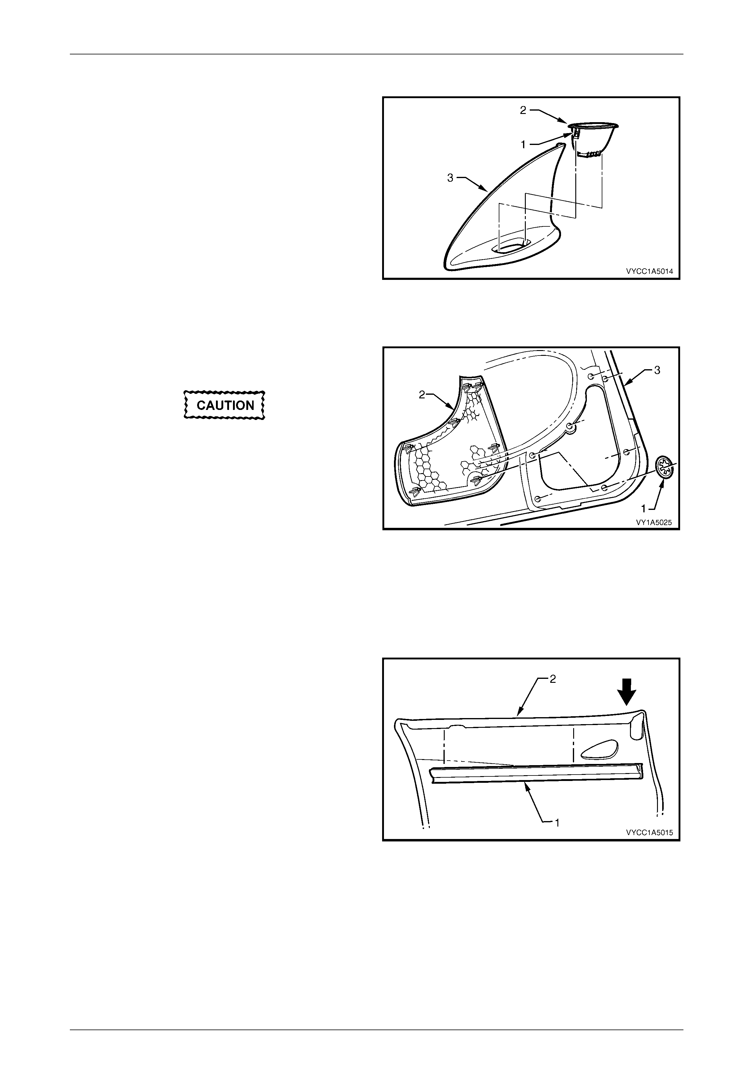
Rear Door Pull Cup
Remove
1 Press the retaining tabs (1), in two places, on the rear
door pull cup (2) and remove the rear door pull cup
from the rear door armrest insert assembly (3).
Reinstall
Reinstallation of the rear door pull cup is the reverse of the
removal procedur e.
Figure 1A5 – 7
Rear Door Radio Speaker Grille
Remove
Take care when removing the rear door radio
speaker grille retainers not to break the
speaker grille shafts on which the retainers
are attached.
1 Remove the retainers (1), in seven places, attaching
the rear door radio speaker grille (2) to the rear door
trim panel assembly (3).
2 Remove the rear door radio speaker grille.
Figure 1A5 – 8
Reinstall
Reinstallation of the rear door radio speaker grille is the reverse of the removal procedure.
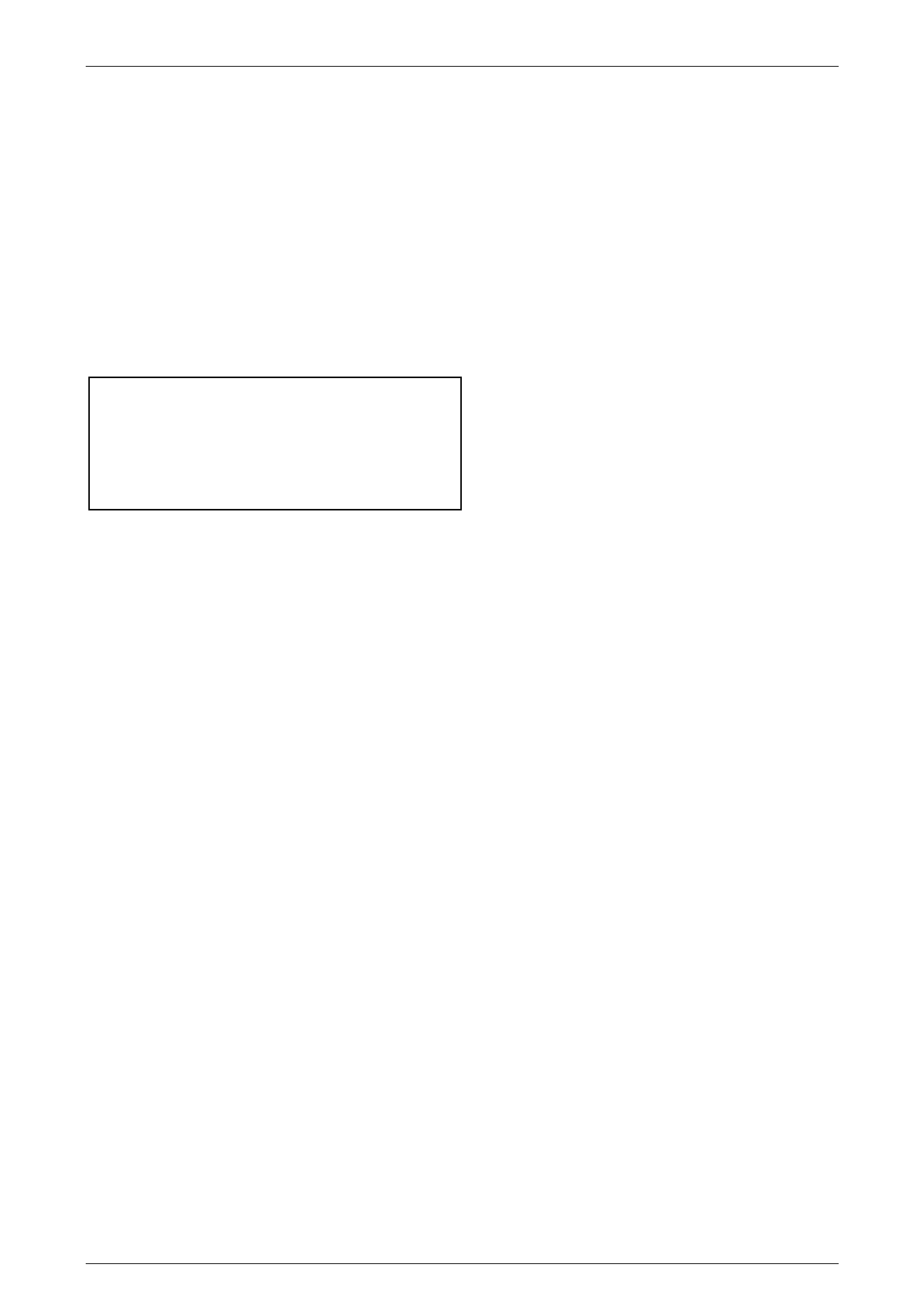
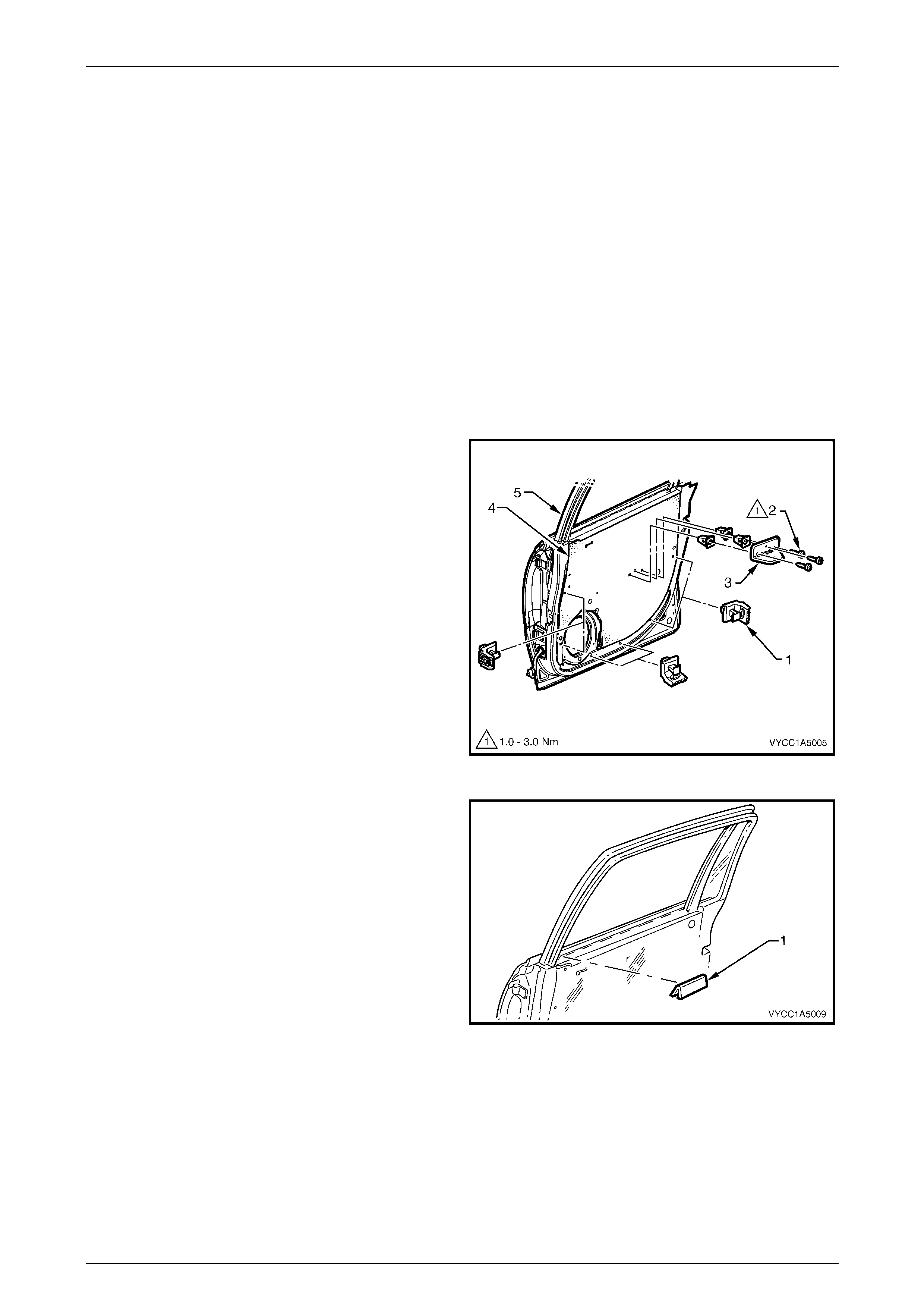
Rear Door Window Inner Sealing Strip
Remove
1 By pushing down on one end, progressively remove
the rear door window inner sealing strip (1) from the
rear door assembly (2).
Reinstall
Reinstallation of the rear door window inner sealing strip is
the reverse of the removal procedure, noting the following:
1 Align sealing strip with the edge of door trim.
Figure 1A5 – 9
Front and Rear Door Assemblies Page 1A5–7
Page 1A5–7
Reinstall
Reinstallation of the rear door trim panel assembly is the reverse of the removal procedure, noting the following:
1 Connect the rear door wiring harness connector to the rear door power window switch (if fitted).
2 Ensure that the rear door handle assembly and the rear inside handle rod are engaged before final fitment, refer to
Section 1A5 Front and Rear Door Assemblies in the MY 2004 VY and V2 Series Service Information.
NOTE
Screws along the bottom of the rear door trim are
wax tip sealing screws. If required, apply sealer
to the screws. Refer to Figure 1A5 – 3.
3 Tighten the screws to the specified torque.
Rear door trim panel assembly retaining
screw torque specification.......................... 1.0 – 3.0 Nm
Rear door pull cup retaining screw
torque specific atio n .................................... 1.0 – 3.0 Nm
Rear door locking rod ferrule retaining
screw torque specification.......................... 1.0 – 3.0 Nm
4 Refit the rear door locking rod knob assembly onto the rear door locking rod using a new orange locking rod knob
retainer, refer to Figure 1A5 – 1.
Front and Rear Door Assemblies Page 1A5–8
Page 1A5–8
2.2 Rear Door Lock Assembly
LT Section – 11-725
Remove
1 Remove the rear window regulator handle assembly (if fitted), refer to Section 1A5 Front Door Assemblies in the
MY 2004 VY and V2 Series Service Information.
2 Remove the rear door inside handle assembly, refer to Section 1A5 Front and Rear Door Assemblies in the
MY 2004 VY and V2 Series Service Information.
3 Remove the rear door trim panel assembly, refer to 2.1 Rear Door Trim Panel Assembly.
4 If required, remove the rear door trim panel assembly
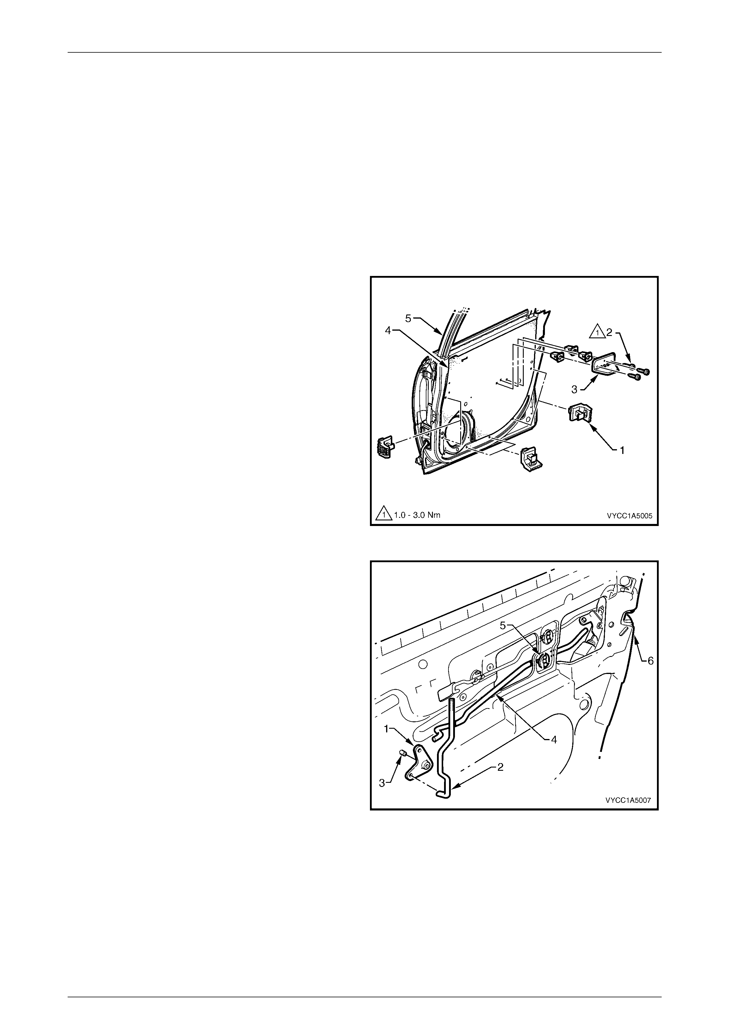
brackets (1), in six places, from the rear door
assembly by levering out the centre pin of each
bracket.
5 If required, remove the screws (2), in three places,
attaching the rear door pull cup bracket (3) to the rear
door assembly and remove the rear door pull cup
bracket.
NOTE
The rear door seal needs only partial removal to
provide access to complete this procedure.
6 Carefully peel off the rear door seal (4) from the rear
door inner panel (5) to gain access for the following
steps.
Figure 1A5 – 10
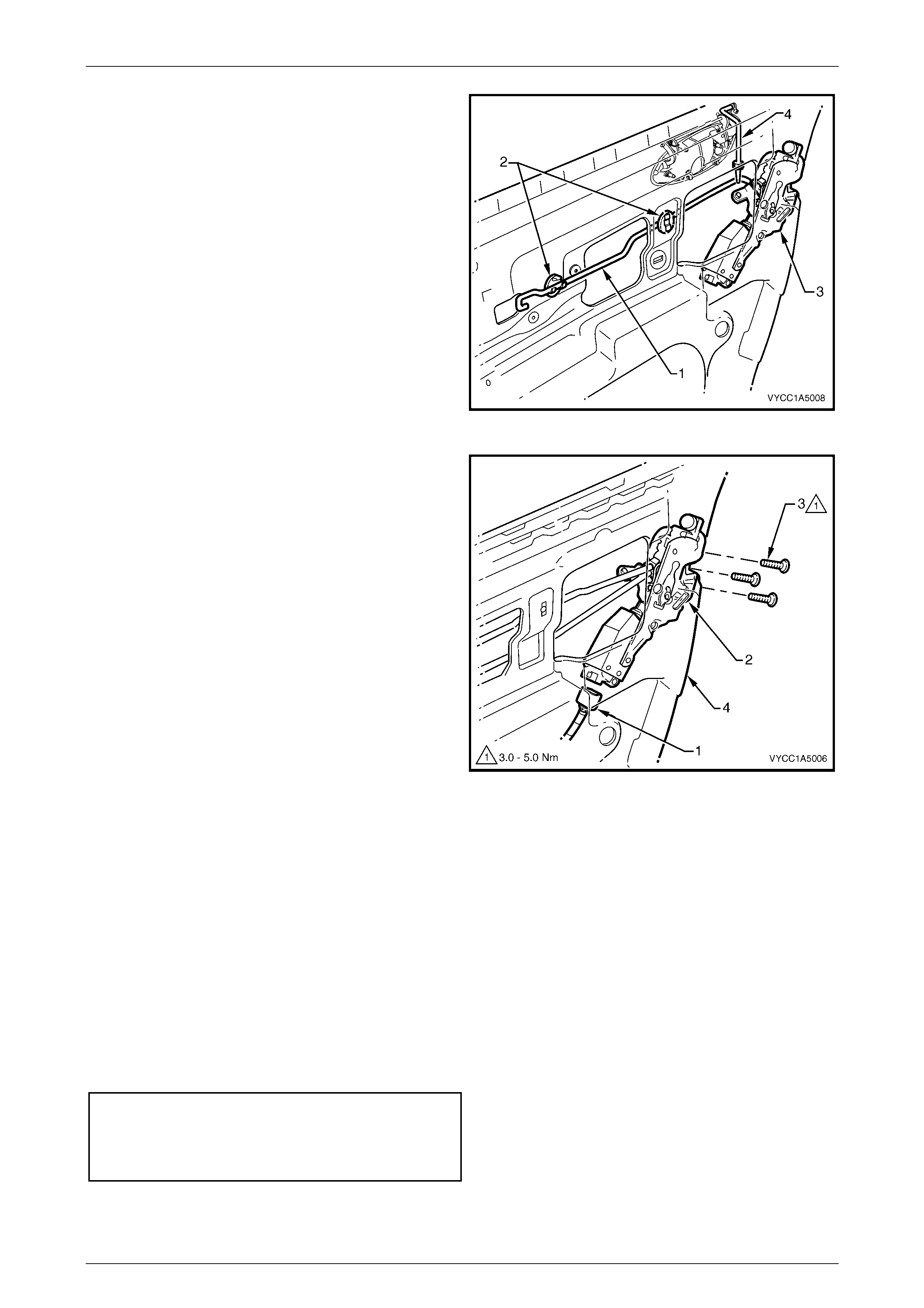
7 Lever the bell crank assembly (1) with the rear door
locking rod (2) from the pivot shaft (3).
8 Remove the rear door locking bell crank rod (4) from
the retainer (5) and rear door lock assembly (6).
Figure 1A5 – 11
Front and Rear Door Assemblies Page 1A5–9
Page 1A5–9
9 Disconnect the rear door inside handle rod (1) from
the two retainers (2) and disengage the rod from the
rear door lock assembly (3) by releasing the rod
retainer.
10 The rear door outside handle rod assembly (4) will
disengage from the rear door lock assembly when the
lock assembly is removed.
Figure 1A5 – 12
11 Disconnect the door wiring harness connector (1) from
the rear door lock assembly (2).
12 If required, remove the rear door window channel
assembly, refer to 2.3 Rear Door Window Channel
Assembly.
13 Remove the screws (3), in three places, attaching the
rear door lock assembly to the door inner panel (4).
14 Remove the lock assembly through the aperture in the
door inner panel.
Figure 1A5 – 13
Disassemble
For disassembly procedures of the rear door lock assembly, refer to Section 1A5 Front and Rear Door Assemblies in the
MY 2004 VY and V2 Series Service Information.
Reassemble
For reassembly procedures of the rear door lock assembly, refer to Section 1A5 Front and Rear Door Assemblies in the
MY 2004 VY and V2 Series Service Information.
Reinstall
Reinstallation of the rear door lock assembly is the reverse of the removal procedure, noting the following:
1 Tighten the screws to the specified torque.
Rear door lock assembly attaching screw
torque specific atio n .................................... 3.0 – 5.0 Nm
Rear door pull cup bracket att achi ng screw
torque specific atio n .................................... 1.0 – 3.0 Nm
2 Ensure that the rear door outside handle rod assembly is engaged correctly with the rear door lock assembly.
3 Ensure that the rear door seal is correctly fitted to the door panel.
Front and Rear Door Assemblies Page 1A5–10
Page 1A5–10
2.3 Rear Door Window Channel Assembly
LT Section No. – 11-020
Remove
1 Remove the rear window regulator handle assembly (where fitted), refer to Section 1A5 Front and Rear Door
Assemblies in the MY 2004 VY and V2 Series Service Information.
2 Remove the rear door inside handle assembly, refer to Section 1A5 Front and Rear Door Assemblies in the
MY 2004 VY and V2 Series Service Information.
3 Remove the rear door trim panel assembly, refer to 2.1 Rear Door Trim Panel Assembly.
4 Remove the rear door belt outer reveal moulding assembly, refer to Section 1A5 Front and Rear Door Assemblies
in the MY 2004 VY and V2 Series Service Information.
5 Partly remove the rear door upper weatherstrip assembly, refer to Section 1A5 Front and Rear Door Assemblies in
the MY 2004 VY and V2 Series Service Information.
6 If required, remove the rear door trim panel assembly
brackets (1), in six places, from the rear door
assembly by levering out the centre pin of each
bracket.
7 If required, remove the screws (2), in three places,
attaching the rear door pull cup bracket (3) to the rear
door assembly and remove the rear door pull cup
bracket.
NOTE
The rear door seal needs only partial removal to
provide access to complete this procedure.
8 Carefully peel off the rear door seal (4) from the rear
door inner panel (5) to gain access for the following
steps.
Figure 1A5 – 14
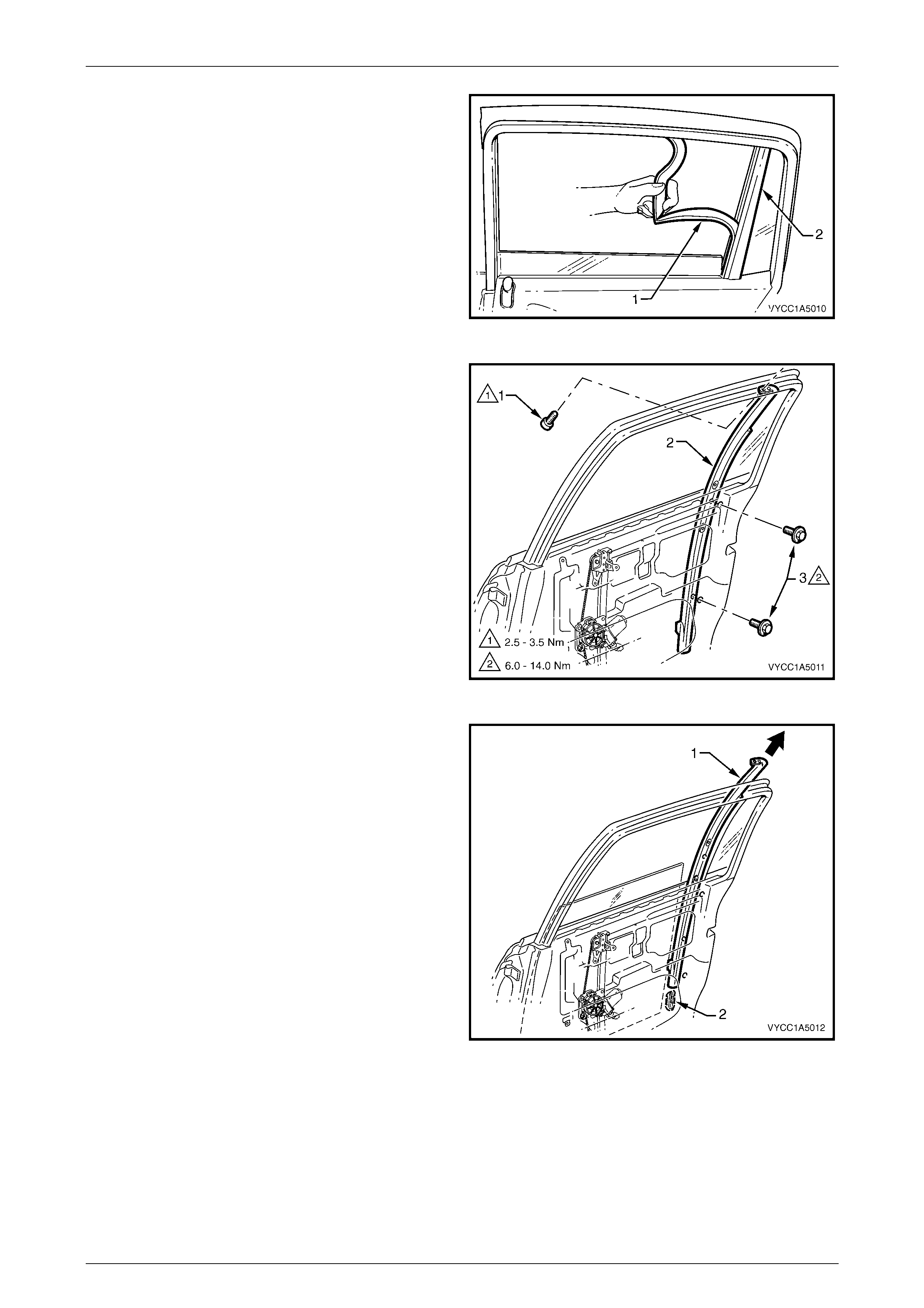
9 Remove the rear door inner panel belt seal (1) from
the rear door assembly.
Figure 1A5 – 15
Front and Rear Door Assemblies Page 1A5–11
Page 1A5–11
10 Carefully remove the rear door window upper
weatherstrip assembly (1) from the rear door window
channel asse mbly (2).
NOTE
Remove the rear door window upper
weatherstrip assembly only from the rear door
window channel assembly. It is not necessary to
completely remove the rear door window upper
weatherstrip assembly.
Figure 1A5 – 16
11 Remove the screws (1), in two places, attaching the
rear door window channel assembly (2) to the top of
the rear door assembly.
12 Remove the screws (3), in two places, attaching the
rear door window channel assembly to the rear door
assembly.
Figure 1A5 – 17
13 Disengage the rear door window channel assembly (1)
from the rear door window assembly (2).
14 In an upward direction, remove the rear door window
channel assembly from the rear door assembly.
Figure 1A5 – 18

Front and Rear Door Assemblies Page 1A5–12
Page 1A5–12
Reinstall
Reinstallation of the rear door window channel assembly is the reverse of the removal procedure, noting the following:
1 Tighten the fasteners to the specified torque.
Rear door window channel assembly
lower retaining screw torque
specification..............................................6.0 – 14.0 Nm
Rear door window channel assembly
upper retaining screw torque
specification................................................2.5 – 3.5 Nm
Rear door pull cup bracket att achi ng
screw torque specification.......................... 1.0 – 3.0 Nm
2 If required, before installing door inner trim panel, adjust the rear door window and regulator, refer to Section 1A5
Front and Rear Door Assemblies in the MY 2004 VY and V2 Series Service Information.
3 Ensure that the rear door seal is correctly sealed against the rear door inner panel.

Front and Rear Door Assemblies Page 1A5–13
Page 1A5–13
3 Torque Wrench Specifications
Rear Door Armrest Insert Assembly Nut........................................0.7 – 0.9 Nm
Rear Door Lock Assembly Attaching Screw ..................................3.0 – 5.0 Nm
Rear Door Locking Rod Ferrule Retaining Screw..........................1.0 – 3.0 Nm
Rear Door Pull Cup Bracket Attaching Screw................................1.0 – 3.0 Nm
Rear Door Pull Cup Retaining Screw ............................................1.0 – 3.0 Nm
Rear Door Trim Panel Assembly Retaining Screw ........................1.0 – 3.0 Nm
Rear Door Window Channel Assembly Lower
Retaining Screw...........................................................................6.0 – 14.0 Nm
Rear Door Window Channel Assembly Upper
Retaining Screw ............................................................................2.5 – 3.5 Nm