
Seat Assemblies Page 1A7–1
Page 1A7–1
Section 1A7
Seat Assemblies
ATTENTION
Before performing any Service Operation or other procedure described in this Section, refer to Section 00
Warnings, Cautions And Notes for correct workshop practices with regard to safety and/or property damage.
1 General Information............................................................................................................................... 3
1.1 Regular Cab............................................................................................................................................................3
1.2 Crew Cab.................................................................................................................................................................4
Front Seats..............................................................................................................................................................4
Rear Seats...............................................................................................................................................................4
2 Service Operations – Regular Cab Front Seats.................................................................................. 5
2.1 Front Seat Usage Chart .........................................................................................................................................5
How To Use This Chart..........................................................................................................................................5
Domestic.............................................................................................................................................................5
Front Seat Type 1...................................................................................................................................................6
Front Seat Type 2...................................................................................................................................................8
2.2 Front Seat-back Pad and Cover Assembly ........................................................................................................10
Remove .................................................................................................................................................................10
Disassemble .........................................................................................................................................................10
Reassemble ..........................................................................................................................................................11
Reinstall ................................................................................................................................................................12
2.3 Front Seat Cushion Pad and Cover Assembly ..................................................................................................13
Remove .................................................................................................................................................................13
Disassemble .........................................................................................................................................................13
Reassemble ..........................................................................................................................................................14
Reinstall ................................................................................................................................................................15
3 Service Operations – Crew Cab Front Seats .................................................................................... 16
3.1 Front Seat Usage Chart .......................................................................................................................................16
How To Use This Chart........................................................................................................................................16
Domestic...........................................................................................................................................................16
4 Service Operations – Crew Cab Rear Seats...................................................................................... 17
4.1 Rear Seat Usage Chart.........................................................................................................................................17
How To Use The Chart.........................................................................................................................................17
Domestic...........................................................................................................................................................17
Rear Seat Type 1 ..................................................................................................................................................18
4.2 Rear Seat Cushion Assembly..............................................................................................................................20
Remove .................................................................................................................................................................20
Disassemble .........................................................................................................................................................21
Cushion Cover and Pad Assembly...................................................................................................................21
Rear Seat Hinge...............................................................................................................................................24
Rear Seat Latch................................................................................................................................................25
Rear Seat Release Button................................................................................................................................26
Reinstall ................................................................................................................................................................26
4.3 Rear Seat-back Insert...........................................................................................................................................28
Remove .................................................................................................................................................................28
Disassemble.....................................................................................................................................................28
Reassemble......................................................................................................................................................29
Reinstall ................................................................................................................................................................29
Techline
Techline
Techline
Techline

Seat Assemblies Page 1A7–2
Page 1A7–2
4.4 Rear Seat-back Assembly....................................................................................................................................30
Remove .................................................................................................................................................................30
Disassemble .........................................................................................................................................................30
Rear Seat-back Cover......................................................................................................................................30
Reinstall ................................................................................................................................................................34
4.5 Head Restraint Assembly....................................................................................................................................35
Remove .................................................................................................................................................................35
Disassemble .........................................................................................................................................................36
Reassemble ..........................................................................................................................................................37
Reinstall ................................................................................................................................................................37
4.6 Head Restraint Sleeve ..........................................................................................................................................38
Remove .................................................................................................................................................................38
Reinstall ................................................................................................................................................................38
5 Torque Wrench Specifications........................................................................................................... 39

Seat Assemblies Page 1A7–3
Page 1A7–3
1 General Information
With the following exceptions, MY 2004 VY Regular Cab and Crew Cab Seat Assemblies information carries over from
MY 2004 VY Series vehicles and MY 2003 VY Regular Cab vehicles.
Regular Cab S vehicles:
• Front seat-back pad and cover assembly
• Front seat cushion pad and cover assemb ly
Crew Cab:
• Front seat assembl ies
• Rear seat assembly
For information not contained within this Section, refer to Section 1A7 Seat Assemblies in the MY 2004 VY and V2
Series Service Information and Section 1A7 Seat Assemblies in the MY 2003 VY Regular Cab Service Information.
1.1 Regular Cab
The front seat assemblies fitted to MY 2004 Regular Cab vehicles carry over from MY 2003 Regular Cab vehicles except
that a new front seat-back pad and cover assembly, and front seat cushion pad and cover assembly are fitted to S
models.
The covers are attached to the pads with a hook and loop system. Hook and loop refers to the seat cover being attached
to the seat pad with a Velcro type material and both the cover and pad being serviced as separate parts. Previously
these have been Surebond type which were only available as an assembly with the pad.

Seat Assemblies Page 1A7–4
Page 1A7–4
1.2 Crew Cab
Front Seats
The front seat assemblies fitted to MY 2004 Crew Cab vehicles carry over from MY 2004 VY Series vehicles. Eight
configurations are fitted depending on Model Level. For further information, refer to 3 Service Operations – Crew Cab
Front Seats.
Rear Seats
The Crew Cab rear seat cushion assembly is hinged at the rear of the base. This allows the rear seat cushion assembly
to be raised for access to a storage area below the seat containing the jack and spare wheel replacement tools. The rear
seat cushion assembly is locked in place by a central latch with the release button located at the front of the seat, above
the transmission tunnel.
Four rear seat cover options are available for MY 2004 Crew Cab vehicles, however, the service procedures are the
same for all rear seats. The covers are attached to the rear seat cushion and seat-back pads using a hook and loop
system and both the cover and pad are serviced as separate parts.
Unique features of the MY 2004 Crew Cab rear seats are:
• Hinged rear seat cushion assembly allowing access to the jack box below the seat,
• Rear cross-beam mounted head restraints,
• Rear seat-back inserts for child restraint access.
• Optional leather or cloth trim for Crew Cab SS.
The rear seat-back assembly incorporates a wire frame that is moulded within the pad and is serviced only as an
assembly. A one-piece moulded plastic base is used instead of a wire frame for the rear seat cushion. This base
supports the cushion pad as well as having provision for the cushion cover to be attached to the base. The base and
cushion pad are servi ced as s eparat e comp onen ts.
Seat Assemblies Page 1A7–5
Page 1A7–5
2 Service Operations – Regular
Cab Front Seats
2.1 Front Seat Usage Chart
How To Use This Chart
Four front seat configurations are fitted to MY 2004 Regular Cab vehicles. The following usage chart is provided to help
determine the seat type fitted to the vehicle. This is important prior to repairs being performed as the failed/damaged part
may not be serviceabl e.
To determine the seat fitted to the vehicle, obtain the vehicle model, which seat requires attention and the seat cover
fabric. Then establish other features of the seat such as the electric movement functions. Using the chart will lead to the
elimination of all other seat combinations, allowing the identification of the type and the construction of the seat. Finally,
refer to the Figure shown in Front Seat Type for a component breakdown of the front seat assembly.
1 Vehicle – Vehicle model identification. For Model Level definitions refer to Section 0A General Information.
2 Seating – Driver front seat or passenger front seat.
3 Fabric – Cloth or leather seat covers.
4 Movement – Indicates the number of movement functions of the seat:
• Two-way – Seat cushion mechanical fore/aft movement.
• Four-way – As two-way plus seat cushion electric front and rear raise/lower.
5 Memory – Indicates if a seat memory module is fitted.
6 SIAB – If the front seat is fitted with a side impact airbag assembly.
7 Construction – Surebond refers to the seat cover being glued to the seat pad. This type is serviced as a cover and
pad assembly only. Hook and Loop refers to the seat cover being attached to the seat pad with a Velcro type
material and both being serviced as separate parts.
8 Head Restraint – Indicates whether fixed or active head restraints are fitted.
9 Front Seat Type – Identifies the seat type and provides reference to the following illustrations which show a
breakdown of the serviced component for each front seat assembly.
Domestic
Vehicle Seating Fabric Movement Memory SIAB Construction Head
Restraint Front Seat Type
(refer to)
Driver Cloth Two-way No No Surebond Fixed MY 2003
Regular Cab
Base
Passenger Cloth Two-way No No Surebond Fixed MY 2003
Regular Cab
Driver Cloth Four-way No No Hook & Loop Fixed 1
(Figure 1A7 – 1)
S
Passenger Cloth Two-way No No Hook & Loop Fixed 2
(Figure 1A7 – 2 )
Techline
Seat Assemblies Page 1A7–6
Page 1A7–6
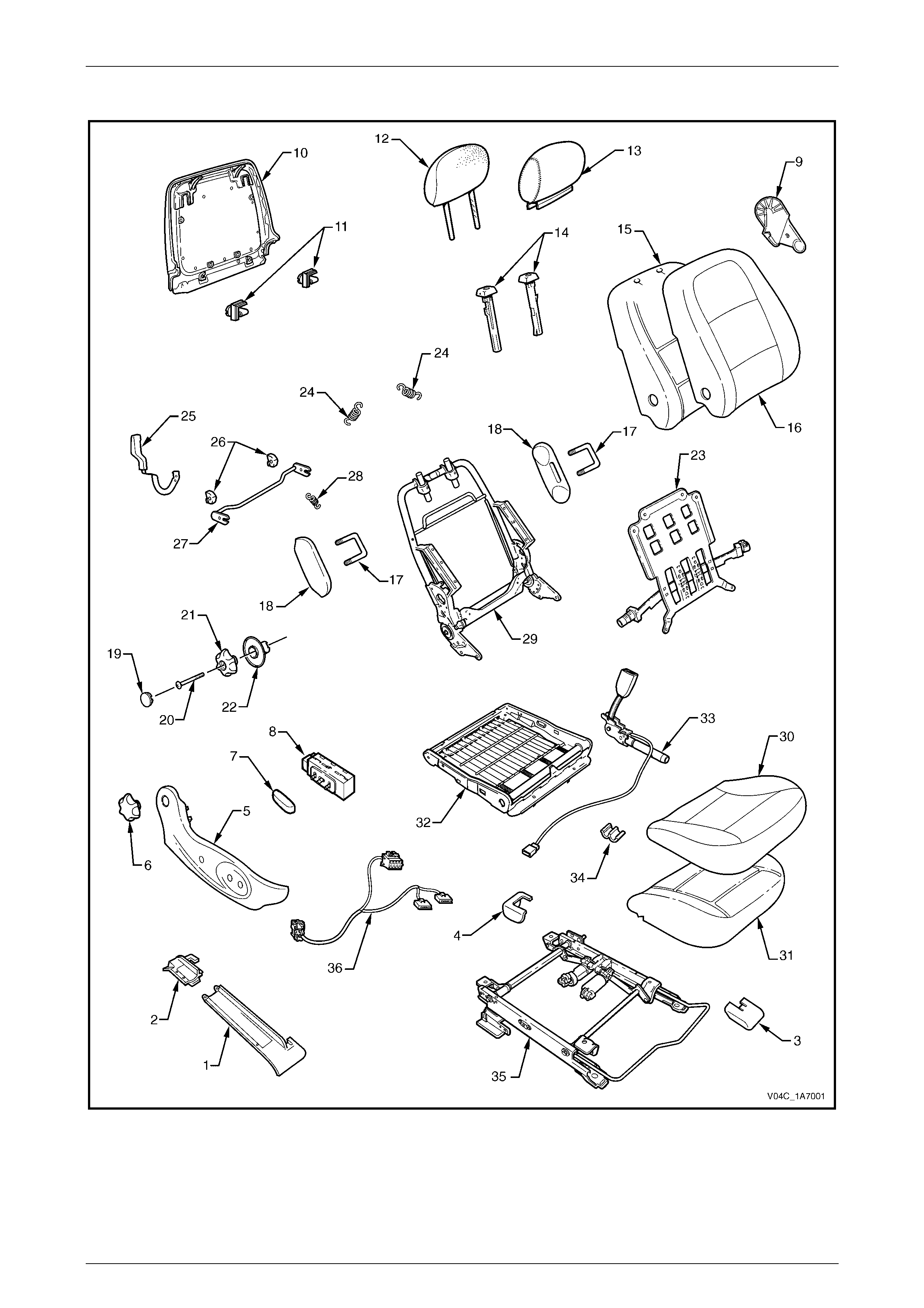
Front Seat Type 1
Figure 1A7 – 1

Seat Assemblies Page 1A7–7
Page 1A7–7
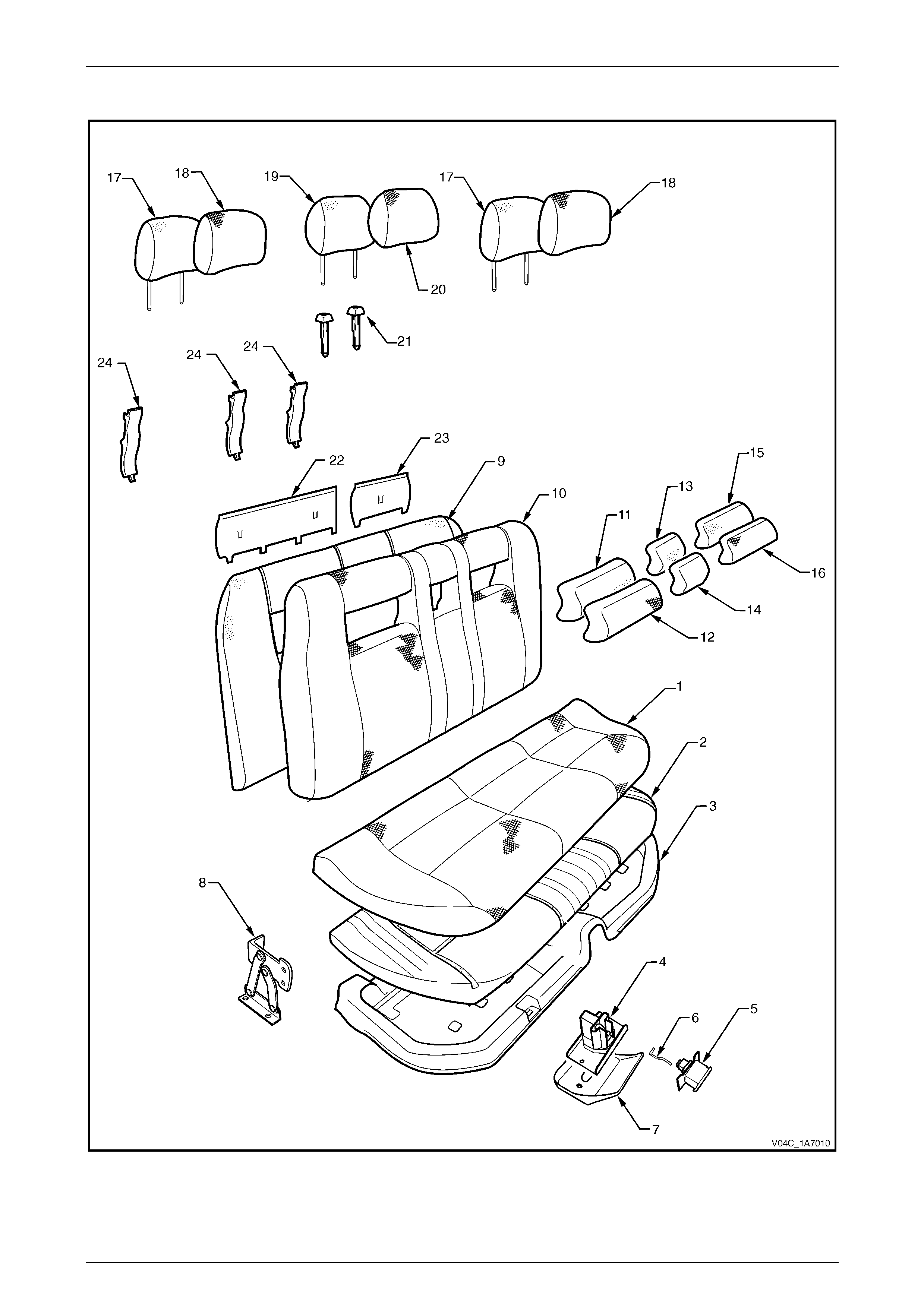
Legend
1 Front Seat Outer Front Cover
2 Front Seat Outer Rear Cover
3 Front Seat Inner Front Cover
4 Front Seat Inner Rear Cover
5 Front Seat Outer Side Cover
6 Recline Adjuster Knob
7 Front Sea t Adju stmen t Switch Knob
8 Front Sea t Adju s tment Switch
9 Front Seat Inner Side Cover
10 Front Seat-back Rear Cover
11 Front Seat-back Rear Cover Retaining Clips
12 Front Seat Head Restraint Pad Assembly
13 Front Seat Head Restraint Cover
14 Front Seat Head Restraint Sleeves
15 Front Seat-back Pad
16 Front Seat-back Cover
17 Front Seat Dummy Block U-bolt
18 Front Seat Dummy Block Insert
19 Lumbar Support Knob Cover
20 Lumbar Support Knob Screw
21 Lumbar Support Knob
22 Lumbar Support Deflector Ring
23 Lumbar Support Assembly
24 Lumbar Support Retaining Spring
25 Dump-latc h Releas e Lever
26 Dump-latc h Releas e Rod Retainer
27 Dump-latc h Releas e Rod
28 Dump-latch Release Spring
29 Front Seat-back Frame Assembly
30 Front Seat Cushion Cover
31 Front Seat Cushion Pad
32 Front Seat Cushion Frame Assembly
33 Seatbelt Buckle and Pretensioner Assembly
34 Wiring Harness Retaining Clip
35 Track and Height Adjust Assembl y
36 Wiring Harness Assembly
Seat Assemblies Page 1A7–8
Page 1A7–8
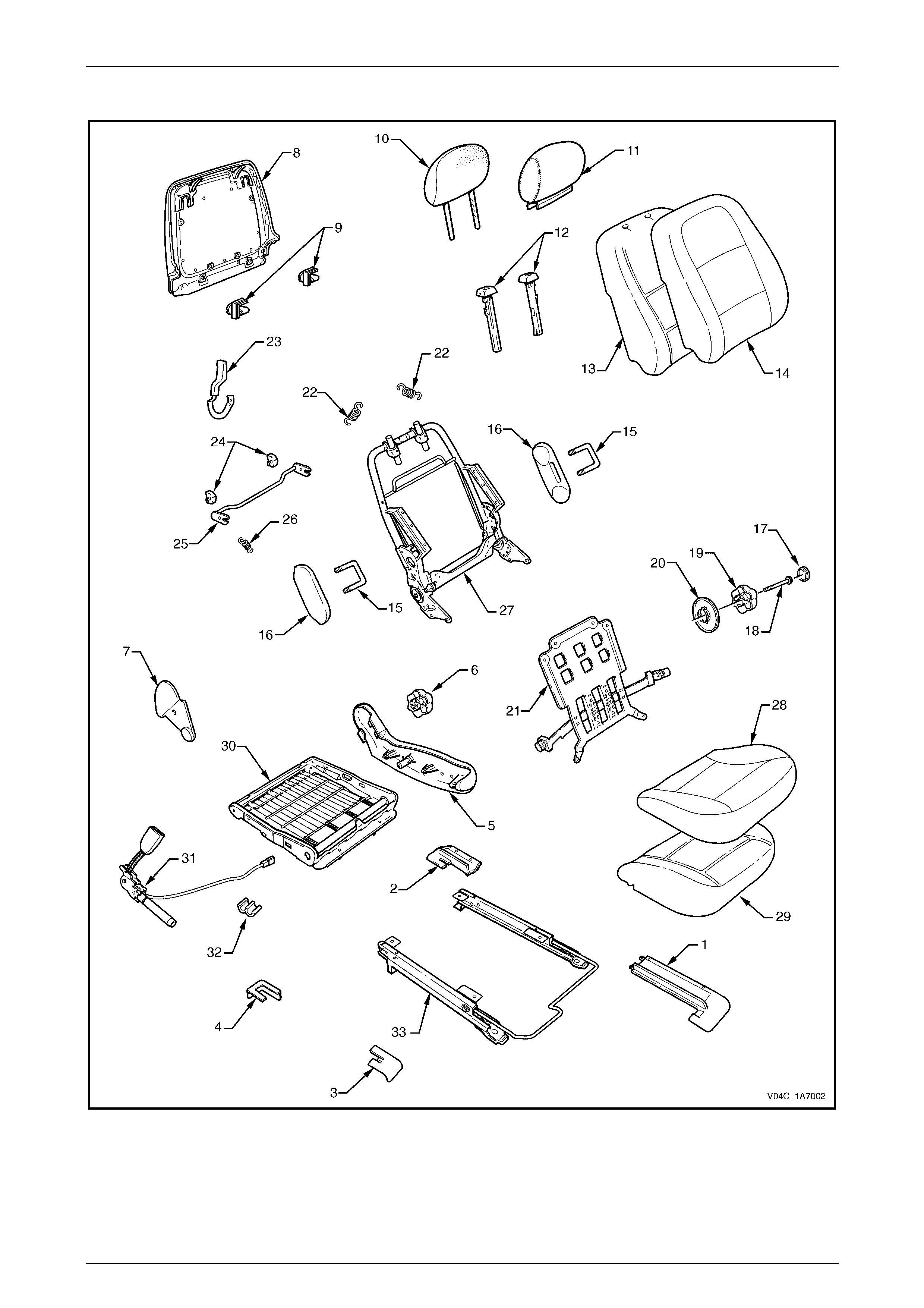
Front Seat Type 2
Figure 1A7 – 2

Seat Assemblies Page 1A7–9
Page 1A7–9
Legend
1 Front Seat Outer Front Cover
2 Front Seat Outer Rear Cover
3 Front Seat Inner Front Cover
4 Front Seat Inner Rear Cover
5 Front Seat Outer Side Cover
6 Recline Adjuster Knob
7 Front Seat Inner Side Cover
8 Front Seat-back Rear Cover
9 Front Seat-back Rear Cover Retaining Clips
10 Front Seat Head Restraint Pad Assembly
11 Front Seat Head Restraint Cover
12 Front Seat Head Restraint Sleeves
13 Front Seat-back Pad
14 Front Seat-back Cover
15 Front Seat Dummy Block U-bolt
16 Front Seat Dummy Block Insert
17 Lumbar Support Knob Cover
18 Lumbar Support Knob Screw
19 Lumbar Support Knob
20 Lumbar Support Deflector Ring
21 Lumbar Support Assembly
22 Lumbar Support Retaining Spring
23 Dump-latc h Releas e Lever
24 Dump-latc h Releas e Rod Retainer
25 Dump-latc h Releas e Rod
26 Dump-latch Release Spring
27 Front Seat-back Frame Assembly
28 Front Seat Cushion Cover
29 Front Seat Cushion Pad
30 Front Seat Cushion Frame Assembly
31 Seatbelt Buckle and Pretensioner Assembly
32 Wiring Harness Retaining Clip
33 Track and Height Adjust Assembl y
Seat Assemblies Page 1A7–10
Page 1A7–10
2.2 Front Seat-back Pad and Cover
Assembly
Remove
Remove the front seat-back pad and cover assembly, refer to Section 1A7, 2.10 Front Seat-back Pad and Cover
Assembly in the MY 2003 VY Regular Cab Service Information.
Disassemble
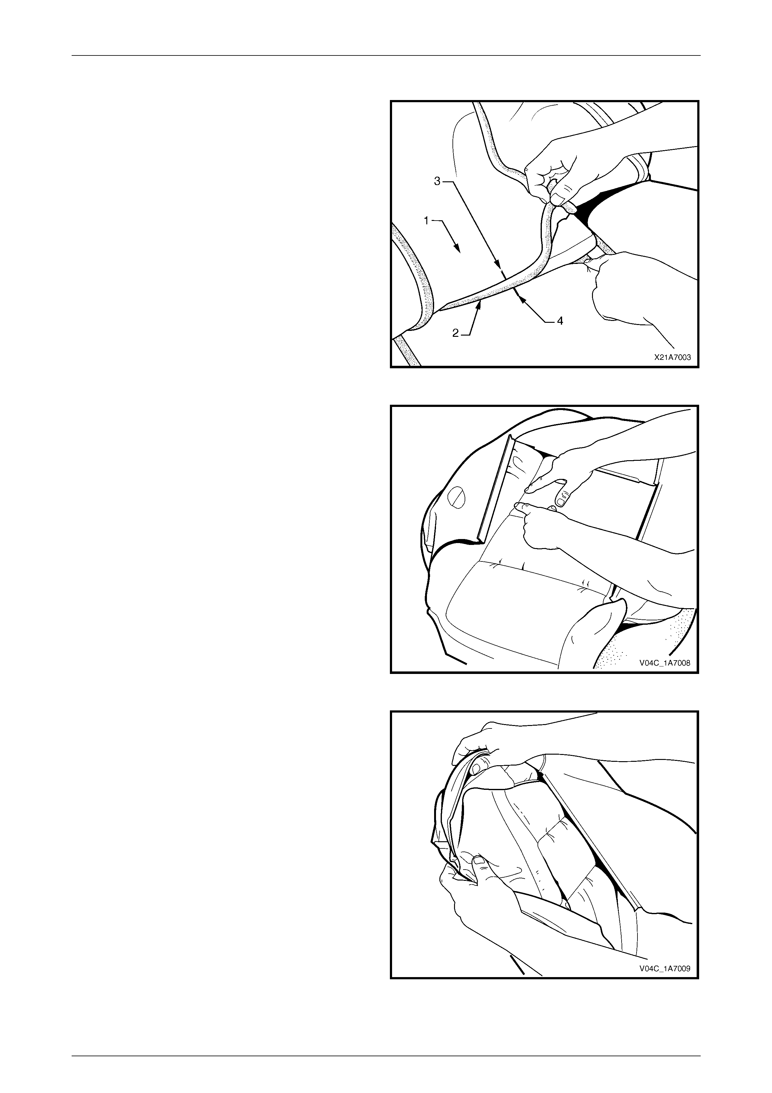
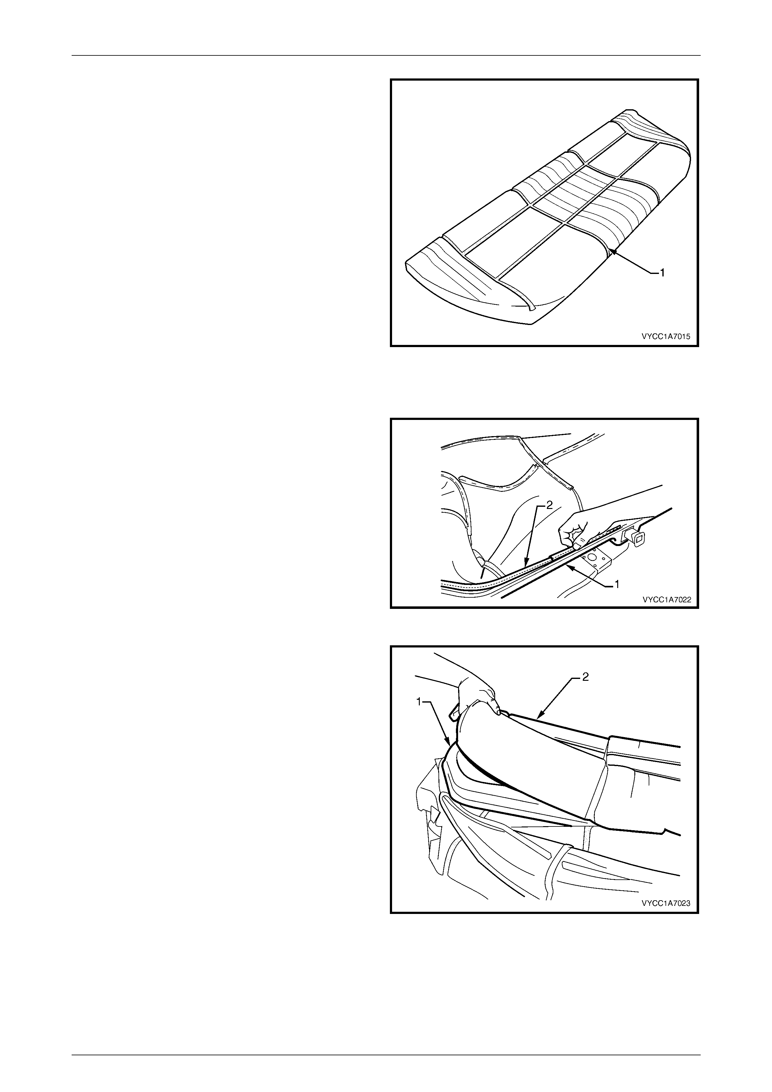
1 Fold the lower corners of the seat-back cover (1) over
the seat-back pad (2).
Figure 1A7 – 3
2 While holding the front seat-back pad (1), pull the
lower corners of the seat-back cover (2), upwards and
away from the front seat-back pad to disengage the
hook and loop strips (3).
3 Pull the cover up and over the upper edge of the pad.
Figure 1A7 – 4
Seat Assemblies Page 1A7–11
Page 1A7–11
Reassemble
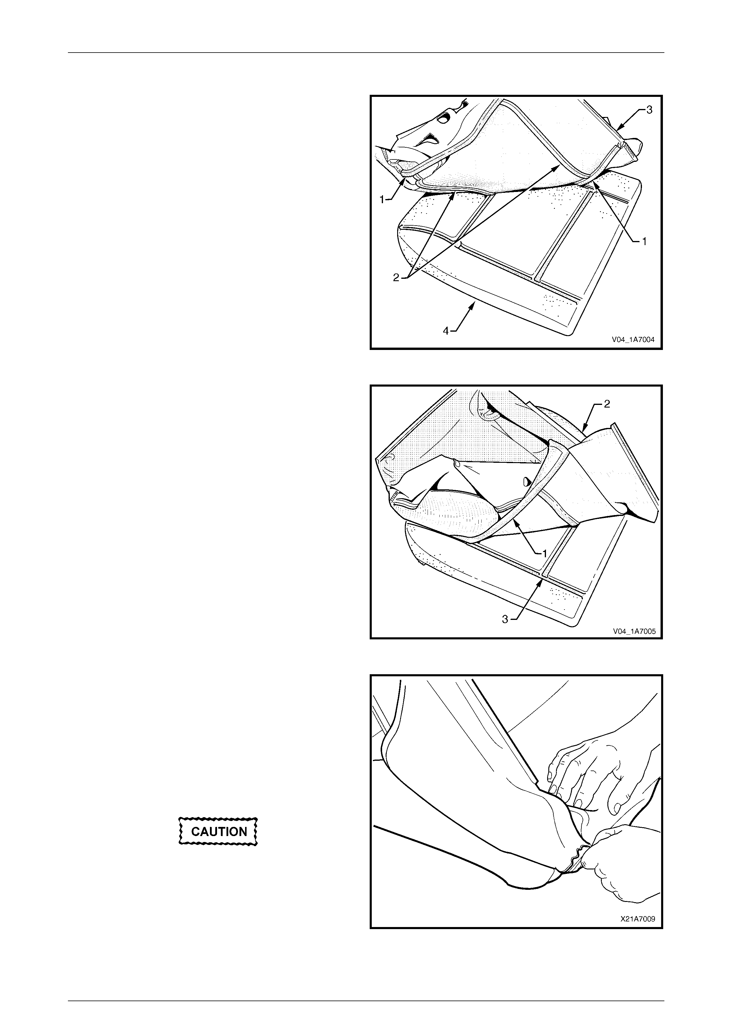
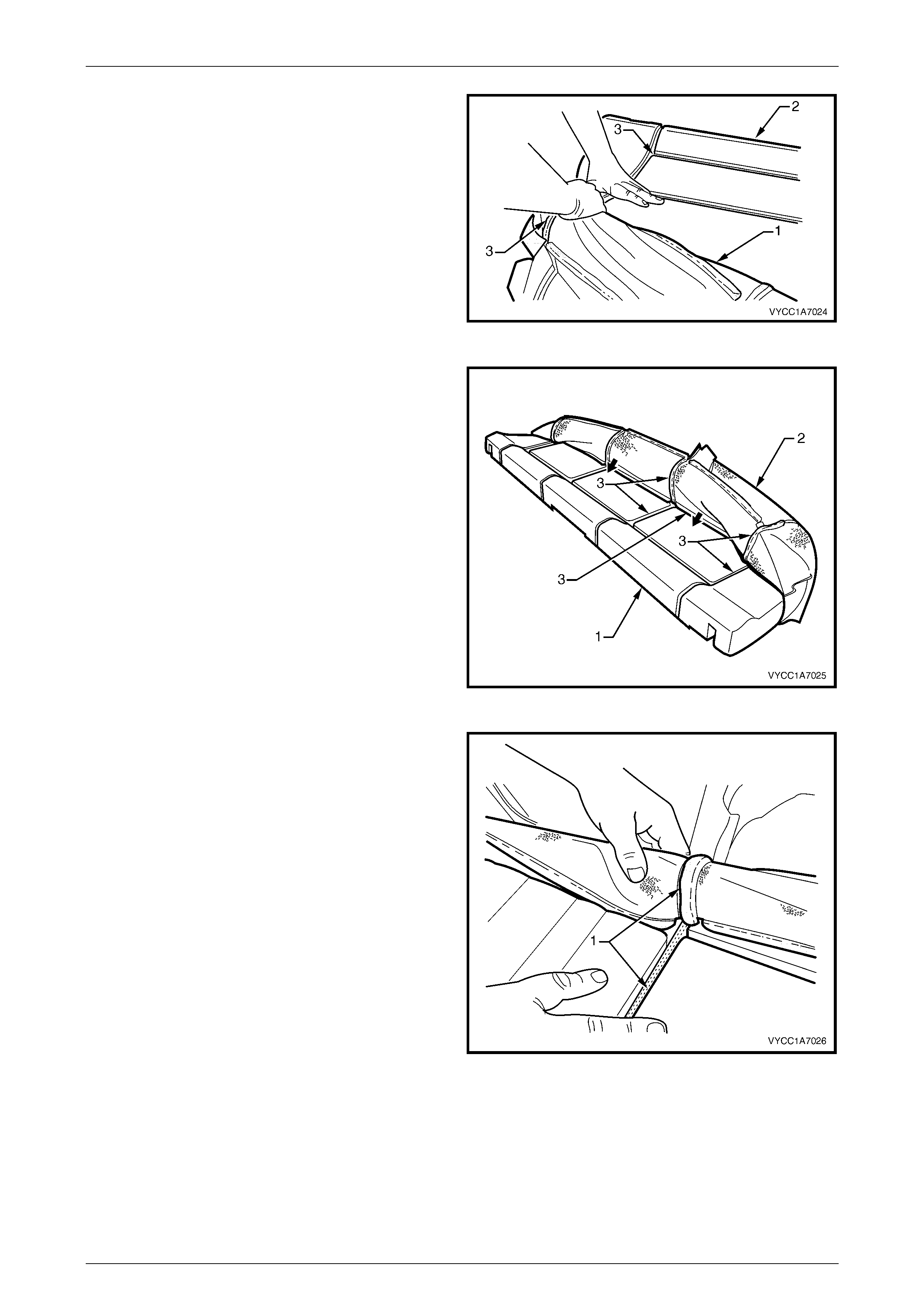
1 W ith the seat-back cover (1) folded at the central
horizontal strip of hook and loop (2), align the centre
mark (3) on the front seat-back cover with the centre
mark (4) on the front seat-back pad.
2 Press the cover firmly into the corresponding groove in
the pad to engage the hook and loop.
Figure 1A7 – 5
3 W ith the cover folded at the two vertical strips of the
hook and loop, press the seat-back cover firmly into
the corresponding grooves in the pad.
Figure 1A7 – 6
4 Roll the upper corners of the cover over the pad.
5 Roll the sides of the cover over the pad.
6 Roll the lower corners of the cover over the pad.
NOTE
Make sure the cover is fitted neatly by hand into
all corners and contours of the pad.
Figure 1A7 – 7

Seat Assemblies Page 1A7–13
Page 1A7–13
2.3 Front Seat Cushion Pad and Cover
Assembly
Remove
Remove the front seat cushion and pad assembly, refer to Section 1A7, 2.13 Front Seat Cushion and Pad Assembly in
the MY 2003 VY Regular Cab Service Information.
Disassemble
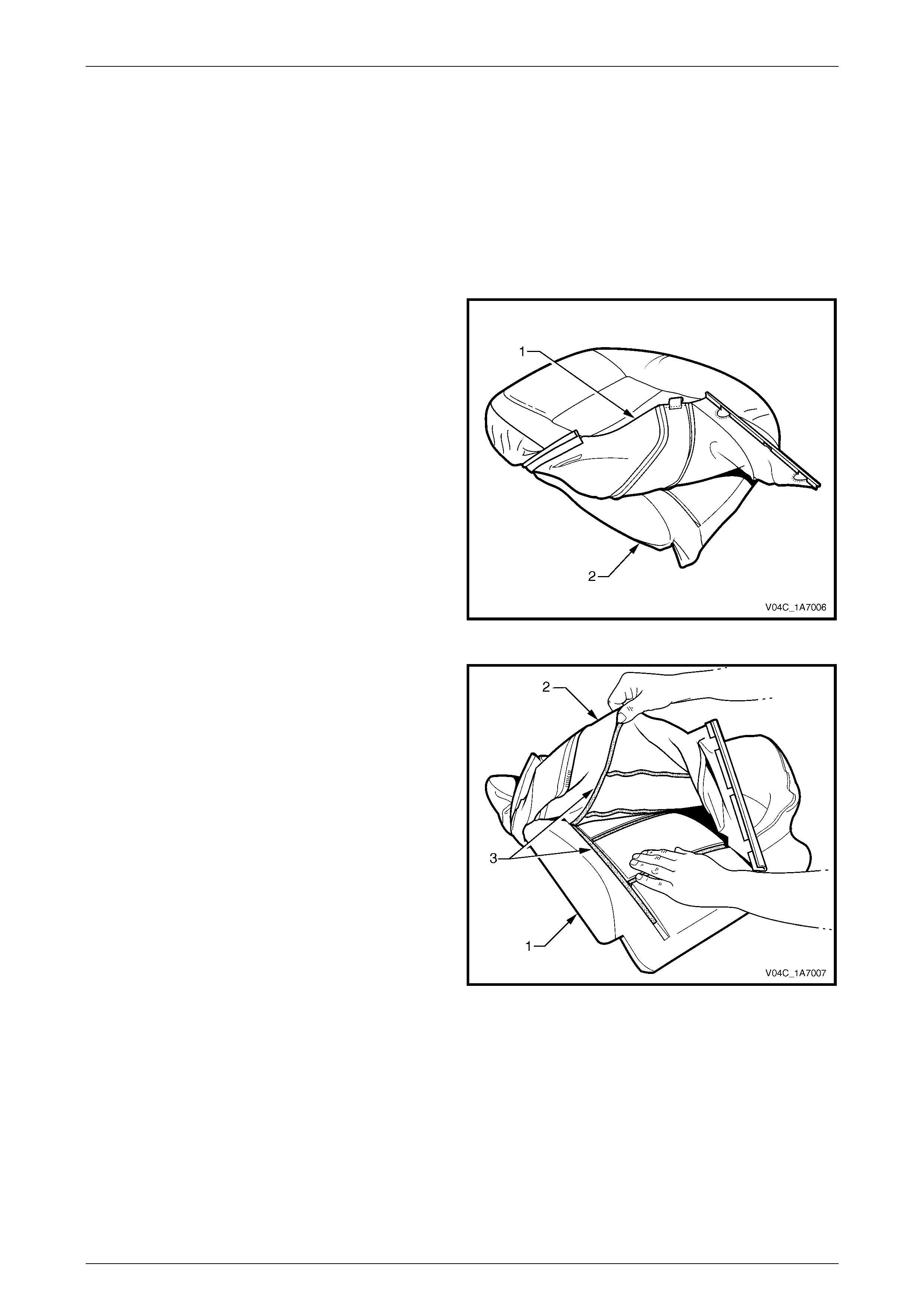
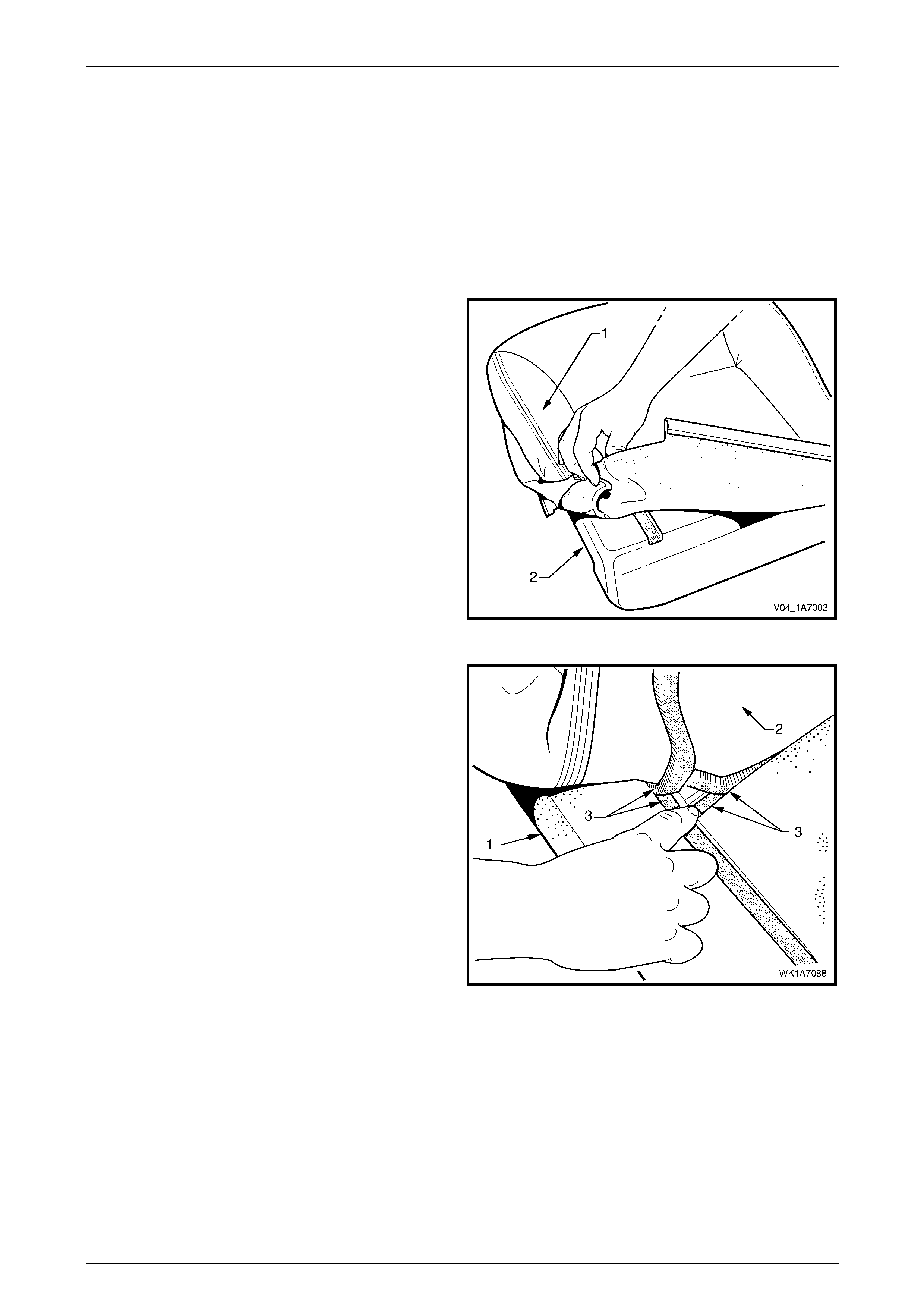
1 Fold the rear corners of the front seat cushion
cover (1) over the front seat cushion pad (2).
Figure 1A7 – 8
2 While holding the pad (1), pull the rear corners of the
cover (2) forward and away from the pad to disengage
the hook and loop strips (3).
3 Pull the cover up and over the forward edge of the
pad.
Figure 1A7 – 9
Seat Assemblies Page 1A7–14
Page 1A7–14
Reassemble
1 Align either of the outer hook and loop strips (1) and
the one or two cross hook and loop strips (2) on the
front seat cushion cover (3) with the front seat cushion
pad (4).
2 Press the folded edge of the cover firmly into the
corresponding groove in the pad to engage the hook
and loop strip.
Figure 1A7 – 10
3 Align and press the outer hook and loop strip (1) on
the cover (2) with the corresponding groove in the
pad (3).
Figure 1A7 – 11
4 Roll the front corners of the cover over the pad.
5 Roll the sides of the cover over the pad.
6 Roll the rear corners of the cover over the seat pad.
NOTE
Make sure the pad is fitted neatly by hand into all
corners and contours of the seat cover.
Do not pull the cover onto the pad from
underneath using the J-strip to make it fit
neatly, as the fabric may be damaged.
Figure 1A7 – 12

Seat Assemblies Page 1A7–16
Page 1A7–16
3 Service Operations – Crew Cab
Front Seats
3.1 Front Seat Usage Chart
How To Use This Chart
Eight front seat configurations are fitted to MY 2004 Crew Cab vehicles. The following usage chart is provided to help
determine the seat type fitted to the vehicle. This is important prior to repairs being performed as the failed/damaged part
may not be serviceabl e.
To determine the seat fitted to the vehicle, obtain the vehicle model, which seat requires attention, and the seat cover
fabric. Then establish other features of the seat such as the electric movement functions. Using the chart will lead to the
elimination of all other seat combinations, allowing the identification of the type and the construction of the seat.
1 Vehicle – Vehicle model identification. For Model Level definitions refer to Section 0A General Information.
2 Seating – Driver front seat or passenger front seat.
3 Fabric – Cloth or leather seat covers.
4 Movement – Indicates the number of movement functions of the seat:
• Two-way – Seat cushion mechanical fore/aft movement.
• Four-way – As two-way plus seat cushion electric front and rear raise/lower.
5 Memory – Indicates if a seat memory module is fitted.
6 SIAB – If the front seat is fitted with a side impact airbag assembly.
7 Construction – Surebond refers to the seat cover being glued to the seat pad. This type is serviced as a cover and
pad assembly only. Hook and Loop refers to the seat cover being attached to the seat pad with a Velcro type
material and both being serviced as separate parts.
8 Head Restraint – Indicates whether fixed or active head restraints are fitted.
9 Front Seat Type – Identifies the seat type and provides reference to the corresponding seat fitted to MY 2004 VY
Series vehicles in the MY 2004 VY and V2 Series Service Information for Service Operations and Diagnostics.
Domestic
Vehicle Seating Fabric Movement Memory SIAB Construction Active Head
Restraint Front Seat Type
(refer to)
Driver Cloth Two-way No No Surebond No MY 2004 VY
Executive
Base
Passenger Cloth Two-way No No Surebond No MY 2004 VY
Executive
Driver Cloth Four-way No No/Opt Hook & Loop No MY 2004 VY
S
S
Passenger Cloth Two-way No No/Opt Hook & Loop No MY 2004 VY
S
Driver Cloth/
Leather Four-way No Yes Hook & Loop No MY 2004 VY
SS
SS
Passenger Cloth/
Leather Two-way No Yes Hook & Loop No MY 2004 VY
SS
Techline
Seat Assemblies Page 1A7–17
Page 1A7–17
4 Service Operations – Crew Cab
Rear Seats
4.1 Rear Seat Usage Chart
How To Use The Chart
Four rear seat configurations are fitted. The following usage chart is provided to help determine the seat type fitted to the
vehicle. This is important prior to repairs being performed as the failed/damaged part may not be serviceable.
To determine the seat fitted to the vehicle, obtain the vehicle model, which seat requires attention and the seat cover
fabric. Using the chart will lead to the elimination of all other seat combinations, allowing the identification of the type and
the construction of the seat. Finally, refer to the Figure shown in Rear Seat Type for a component breakdown of the rear
seat assembly .
1 Vehicle – Vehicle model identification. For Model Level definitions refer to Section 0A General Information.
2 Seating – Rear cushion or seat-ba ck.
3 Fabric – Cloth or leather seat covers.
4 Inserts – Cloth or leather covers.
5 Construction – Hook and Loop refers to the seat cover being attached to the seat pad with a Velcro type material
and both being serviced as separate parts.
6 Head Restraint – Indicates whether fixed or active head restraints are fitted.
7 Rear Seat Type – Identifies the seat type and provides reference to the following illustrations, which show a
breakdown of the serviced component for each rear seat assembly.
Domestic
Vehicle Seating Fabric Construction Inserts Head Restraint Rear Seat Type
(refer to)
Cushion
Base
Seat-back Cloth Hook and Loop Cloth Fixed and mounted In
upper cross-beam 1
(Figure 1A7 – 13)
Cushion
S
Seat-back Cloth Hook and Loop Cloth Fixed and mounted In
upper cross-beam 1
(Figure 1A7 – 13)
Cushion
SS
Seat-back Cloth Hook and Loop Cloth Fixed and mounted In
upper cross-beam 1
(Figure 1A7 – 13)
Cushion
SS
Seat-back Leather Hook and Loop Leather Fixed and mounted In
upper cross-beam 1
(Figure 1A7 – 13
Seat Assemblies Page 1A7–18
Page 1A7–18
Rear Seat Type 1
Figure 1A7 – 13

Seat Assemblies Page 1A7–19
Page 1A7–19
Legend
1 Rear Seat Cushion Cover
2 Rear Seat Cushion Pad
3 Rear Seat Cushion Base
4 Rear Seat Cushion Latch
5 Rear Seat Cushion Latch Releas e Button
6 Rear Seat Cushion Latch Releas e Rod
7 Rear Seat Latch Cover
8 Rear Seat Cushion Hinge, Two Places
9 Rear Seat-back Cushi on Pad and Frame
10 Rear Seat-back Cushion, Cover
11 Rear Seat-back Insert Pad, Left-hand
12 Rear Seat-back Ins ert Cover, Left -hand
13 Rear Seat-back Insert Pad, Centre
14 Rear Seat-back Ins ert Cover, Centre
15 Rear Seat-back Insert Pad Right-hand
16 Rear Seat-back Ins ert Cover, Ri ght-hand
17 Rear Head Restraint P ad, Outer
18 Rear Head Restraint Cover, Outer
19 Rear Head Restraint P ad, Cent re
20 Rear Head Restraint Cover, Centre
21 Head Restraint S l eeve, Six Places
22 Rear Seat-back Ins ert Opening Cover, Ri ght -hand
23 Rear Seat-back Insert Opening Cover, Left-hand
24 Seatbelt Guide, Three Places
Seat Assemblies Page 1A7–20
Page 1A7–20
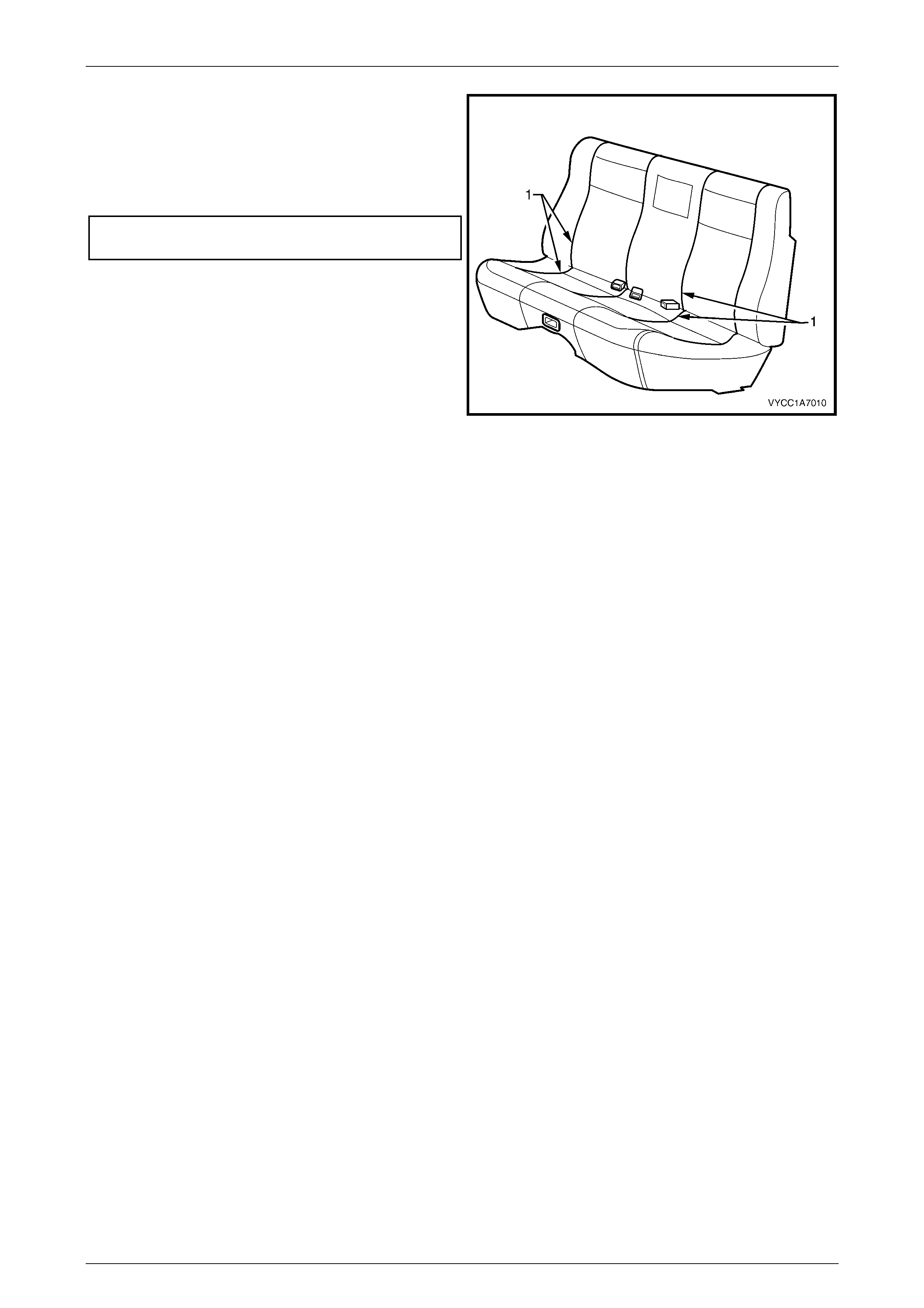
4.2 Rear Seat Cushion Assembly
LT Section No. – 14-330
Remove
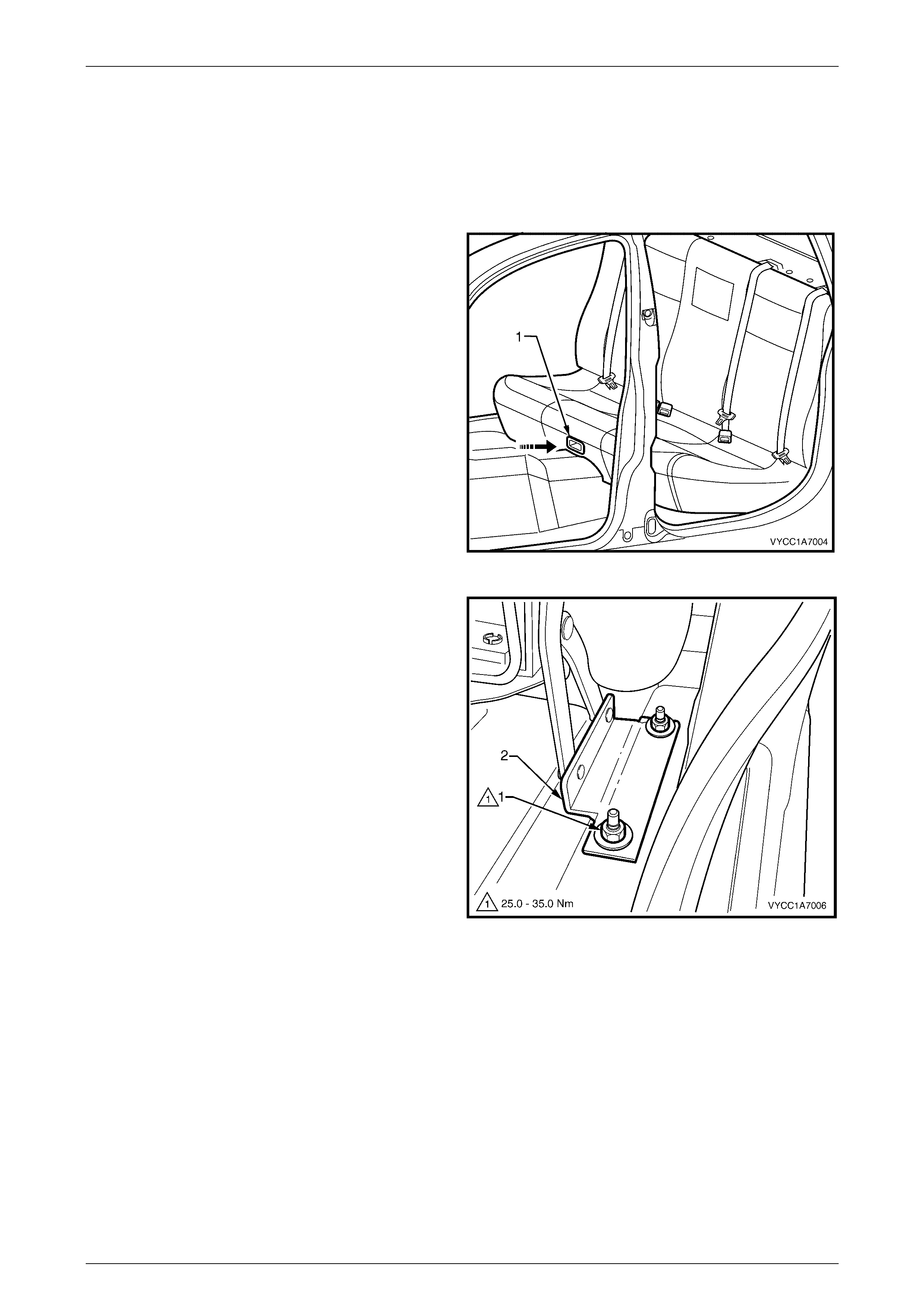
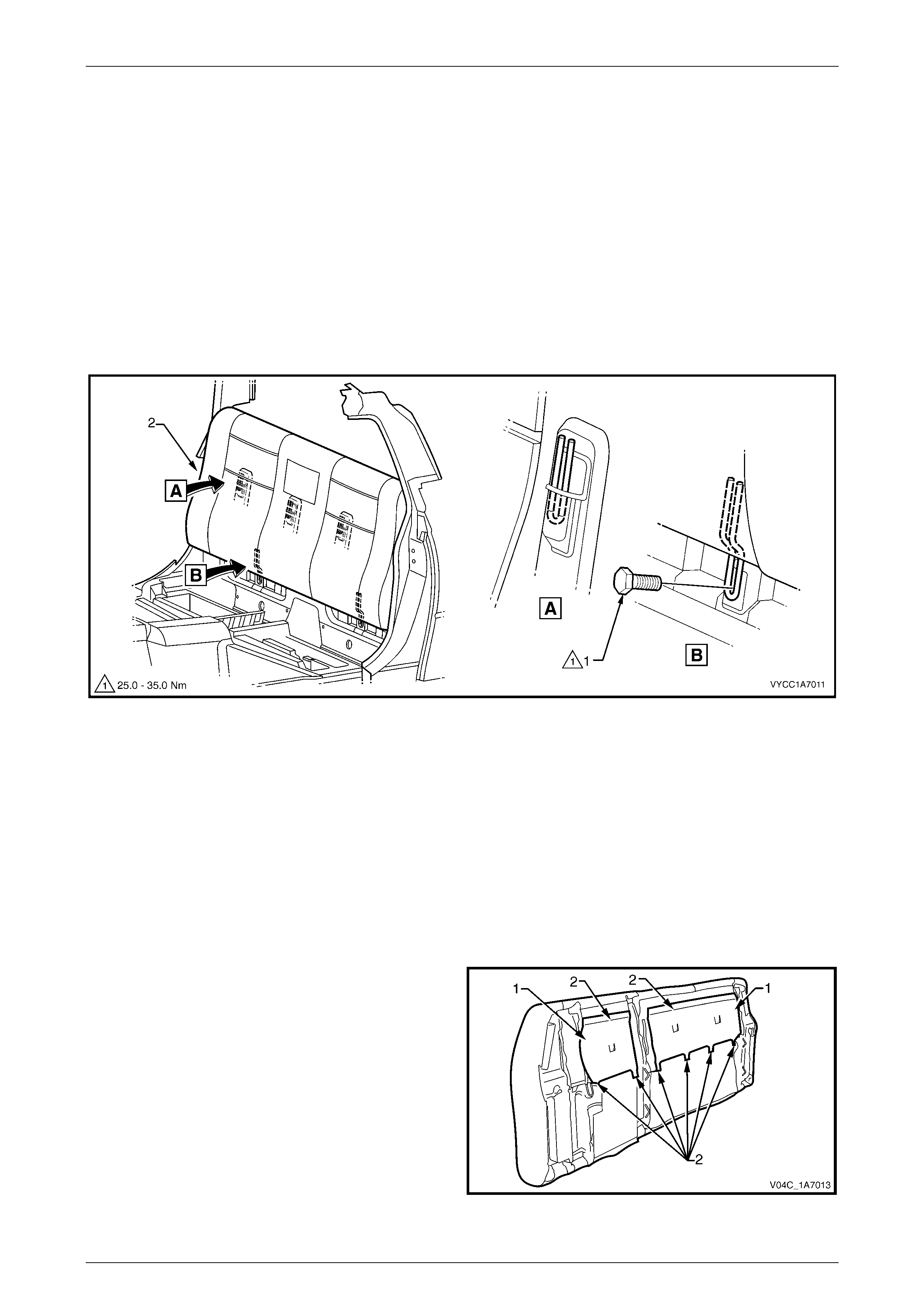
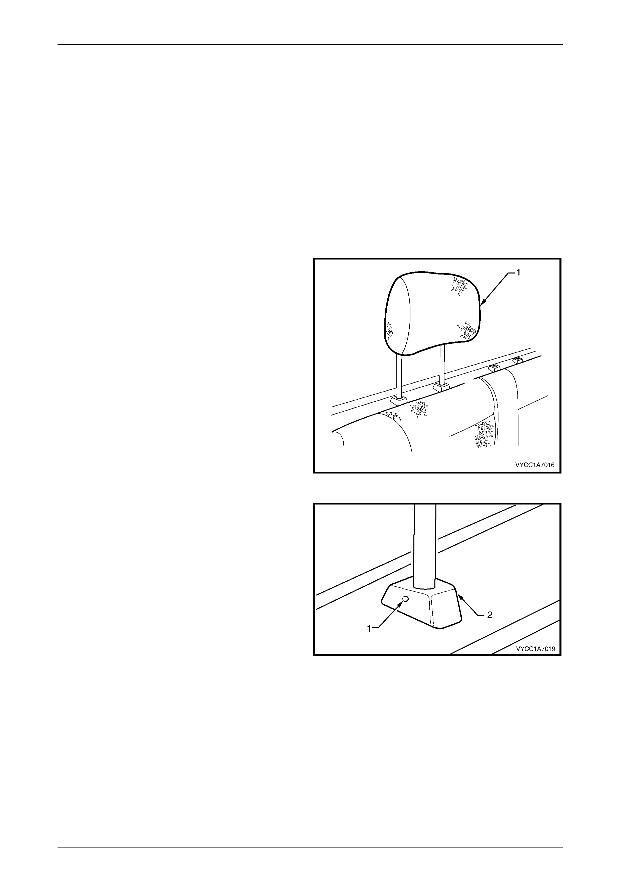
1 Press the rear seat release button (1) inward and lift
the rear seat cushion to the raised position.
2 Remove the rocker panel cover extension, refer to
Section 1A8, 2.2 Rocker Panel Cover Extension.
Figure 1A7 – 14
3 Remove the nut (1) two places each side, attaching
the rear seat cushion assembly hinge (2) to the
vehicle.
4 Remove the rear seat cushion assembly from the
vehicle by manoeuvring it through either rear door
opening.
Figure 1A7 – 15
Seat Assemblies Page 1A7–21
Page 1A7–21
Disassemble
Cushion Cover and Pad Assembly
Remove
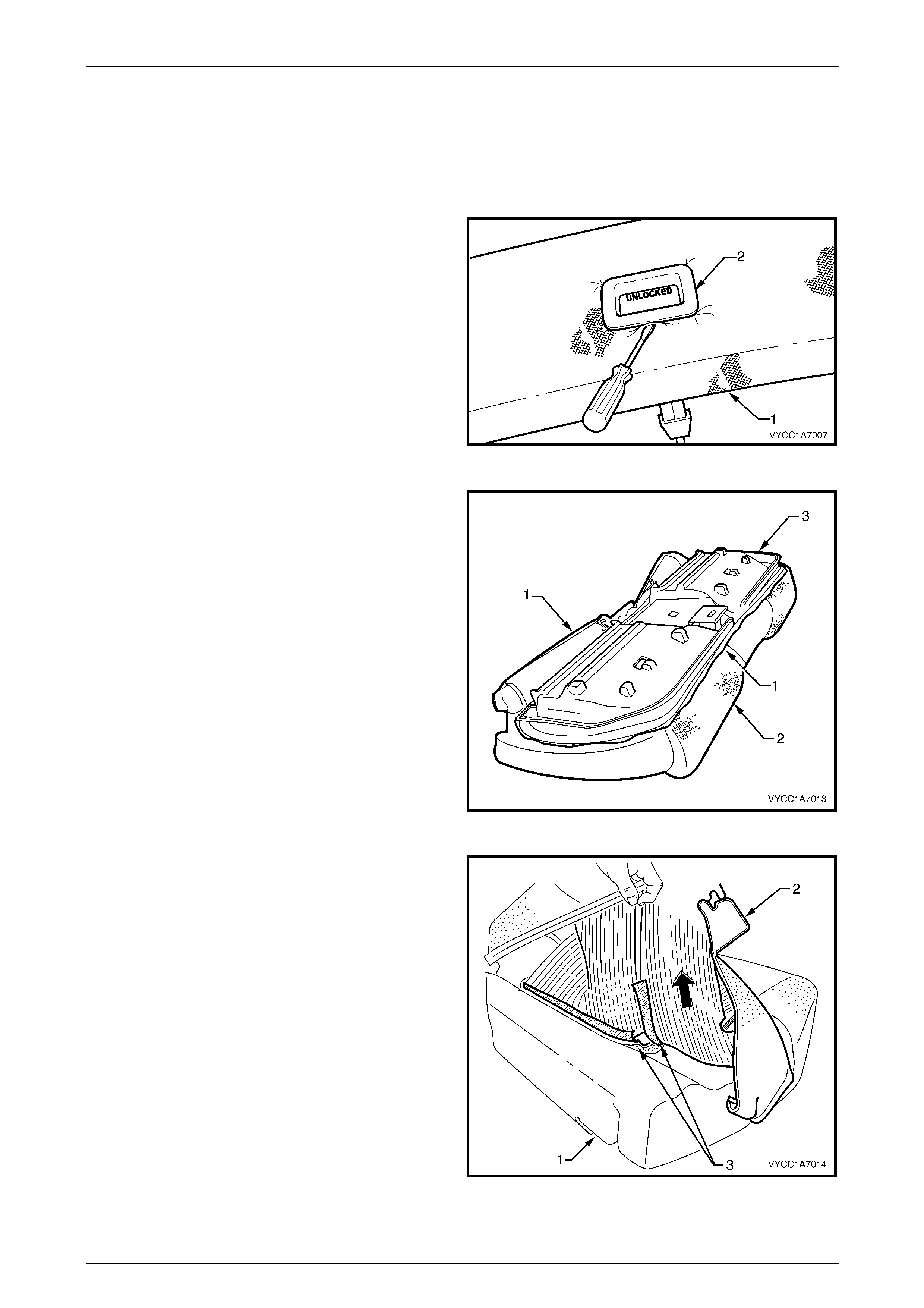
1 Using a suitable screwdriver or similar, carefully prise
the cushion cover (1) over the seat latch
escutcheon (2).
Figure 1A7 – 16
2 Prise up the retaining strips (1), attaching the cushion
cover (2) to the rear seat cushion base (3).
Figure 1A7 – 17
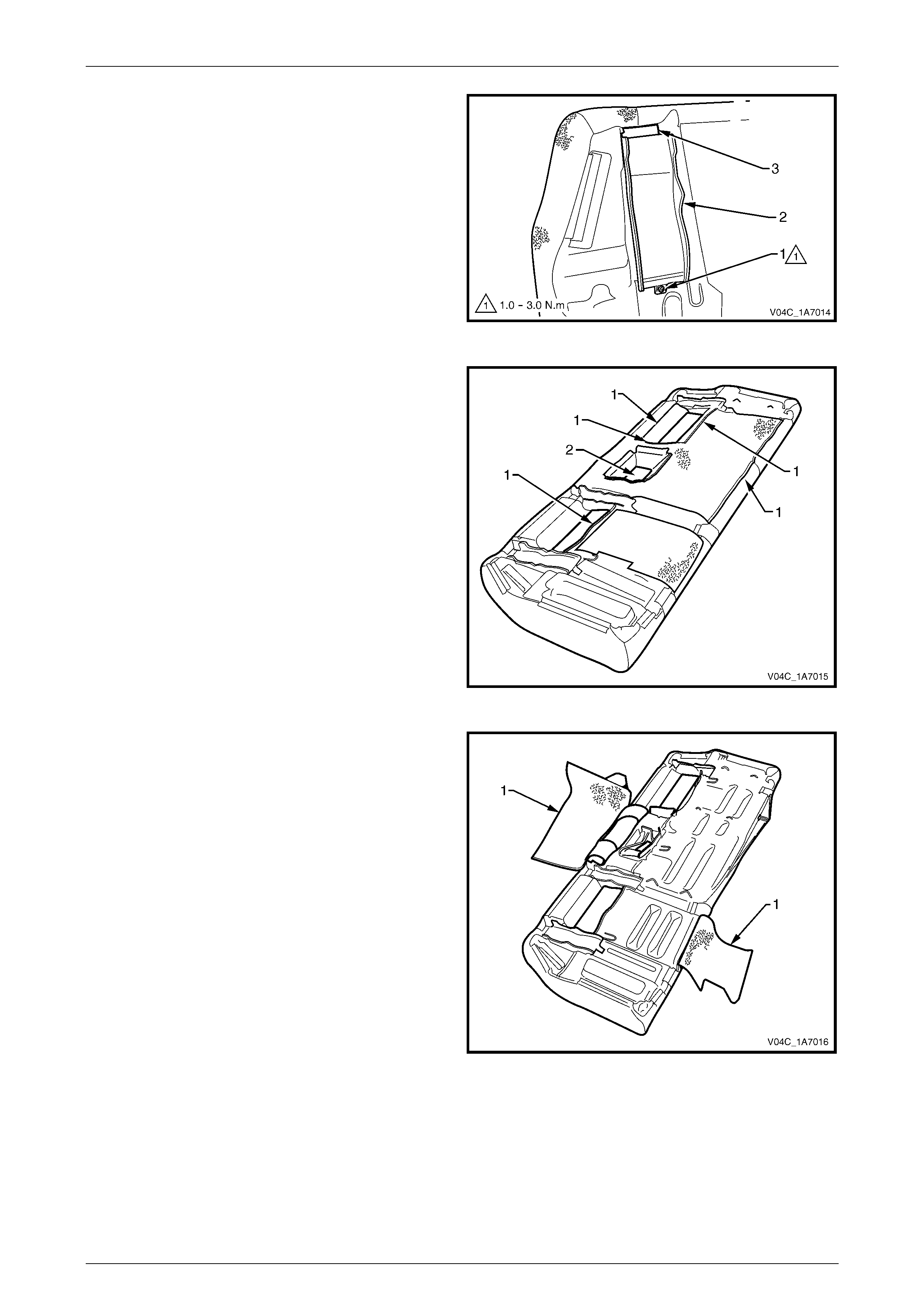
3 Starting at a rear corner of the cushion assembly (1),
carefully peel the cushion cover (2) back, releasing the
hook and loop strips (3).
Figure 1A7 – 18
Seat Assemblies Page 1A7–22
Page 1A7–22
4 Carefully continue folding the cover back releasing the
hook and loop strip (1), in 10 places at the locations
shown.
5 Remove the cover and cushion from the base.
Figure 1A7 – 19
Reinstall
1 Place the rear seat base (1) upside down and install
the cushion cover front retaining strip (2), two places
into the base.
Figure 1A7 – 20
2 Turn the rear seat base (1) over and position the rear
seat cushion pad (2) to the base.
Figure 1A7 – 21
Seat Assemblies Page 1A7–23
Page 1A7–23
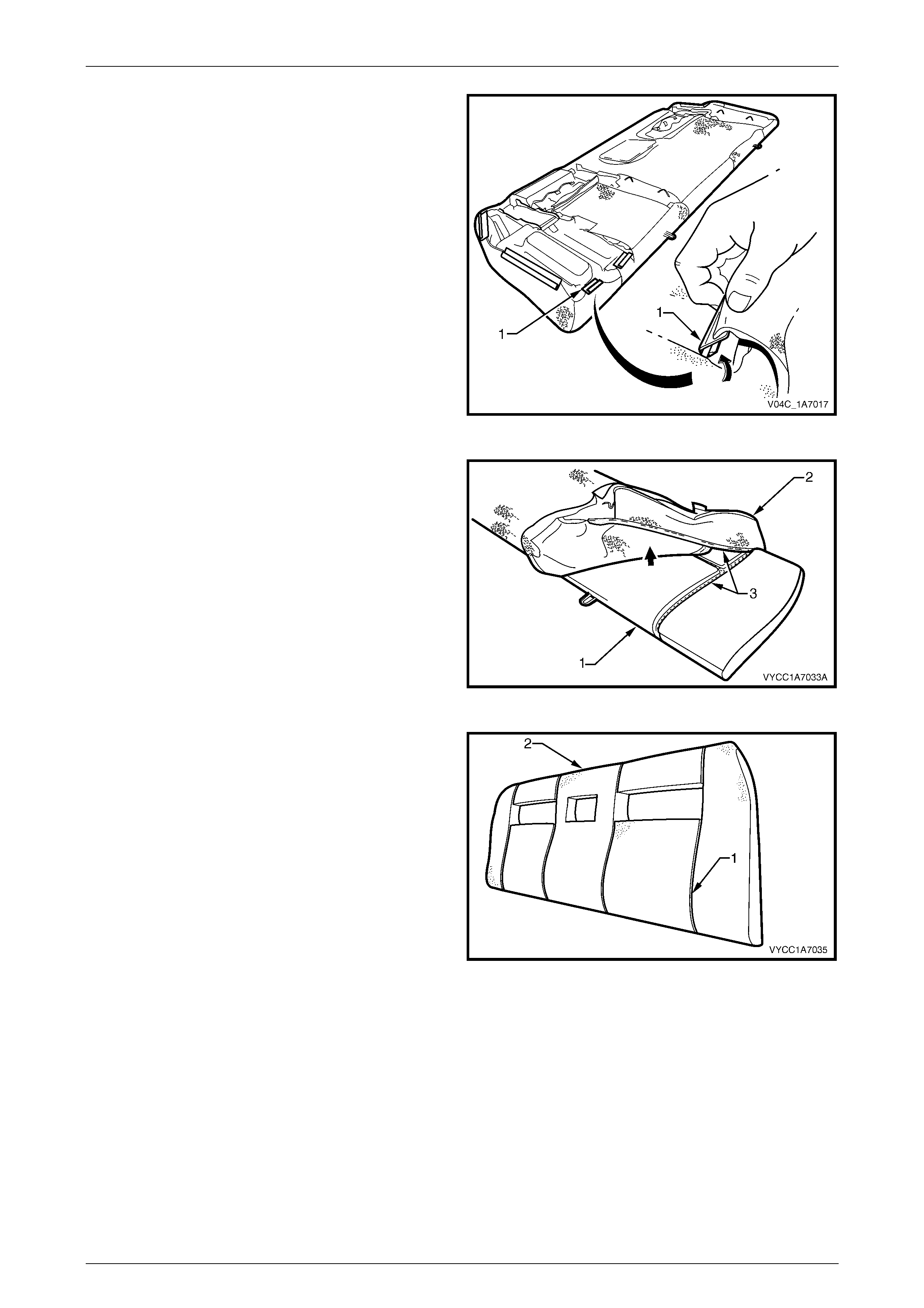
3 Starting at the front corner, pull the cushion cover (1)
over the top of the cushion pad (2), aligning the hook
and loop strips (3).
4 Repeat step 3 for the other side of the cushion
assembly.
Figure 1A7 – 22
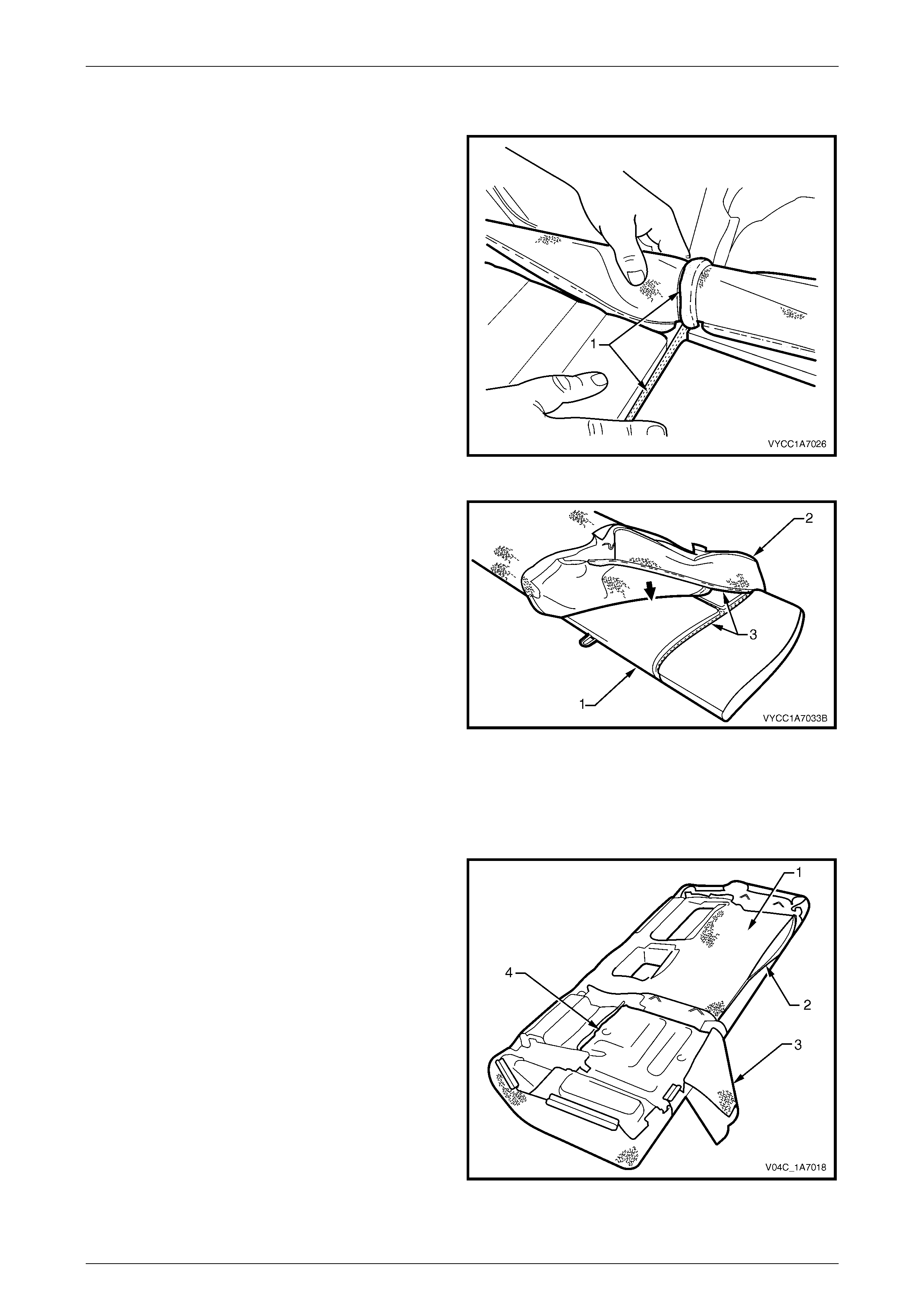
5 Working from one corner of the cushion pad (1), and
pull the cushion cover (2) over the cushion pad,
aligning the hook and loop strips (3).
Figure 1A7 – 23
6 Align the hook and loop strips (1) and push the cover
into the corresponding groove. Ensuring the mating
strips are attached fully and are aligned correctly.
Figure 1A7 – 24
Seat Assemblies Page 1A7–24
Page 1A7–24
7 Pull the cushion cover (1) over the rear of the cushion
pad and fasten the rear retainer strip (2), three places.
NOTE
Ensure the rear retainer strips are fitted to the
second inner groove of the base.
Figure 1A7 – 25
8 Fold the corners of the cushion cover (1) neatly in
behind the cushion pad.
NOTE
Ensure the cushion cover is fitted neatly by hand
into all corners and grooves and it is free from
any creases. As part of their designed
appearance, leather cushion covers have
inherent minor cr eas es in the mater ial.
Figure 1A7 – 26
Rear Seat Hinge
Remove
1 If the rear seat cushion pad and cover assembly has
not been removed, fold the rear seat cushion pad and
cover assembly (1) back sufficiently to gain access to
the hinge and attaching bolt (2).
2 Remove the bolt, four places, attaching the hinge to
the rear seat cushion base.
3 Remove the hinge past the cushion cover.
Figure 1A7 – 27
Seat Assemblies Page 1A7–25
Page 1A7–25
Reinstall
1 If the seat cushion pad and cover assembly (1) has not been removed, fold the rear seat cushion pad and cover
assembly back sufficiently to gain enough access to install the hinge and attaching bolt (2), four places, refer to
Figure 1A7 – 27.
2 Position the hinge to the base and install the four attaching bolts.
3 Tighten the attaching bolts to the correct torque specification.
Rear seat cushion hinge attaching bolt
torque specification ................................ 18.0 – 20.0 Nm
4 Ensure the cushion cover is fitted neatly into the corners of the cushion and is free from any creases.
NOTE
As part of their designed appearance, leather
cushion covers have inherent minor creases in
the material.
Rear Seat Latch
Remove
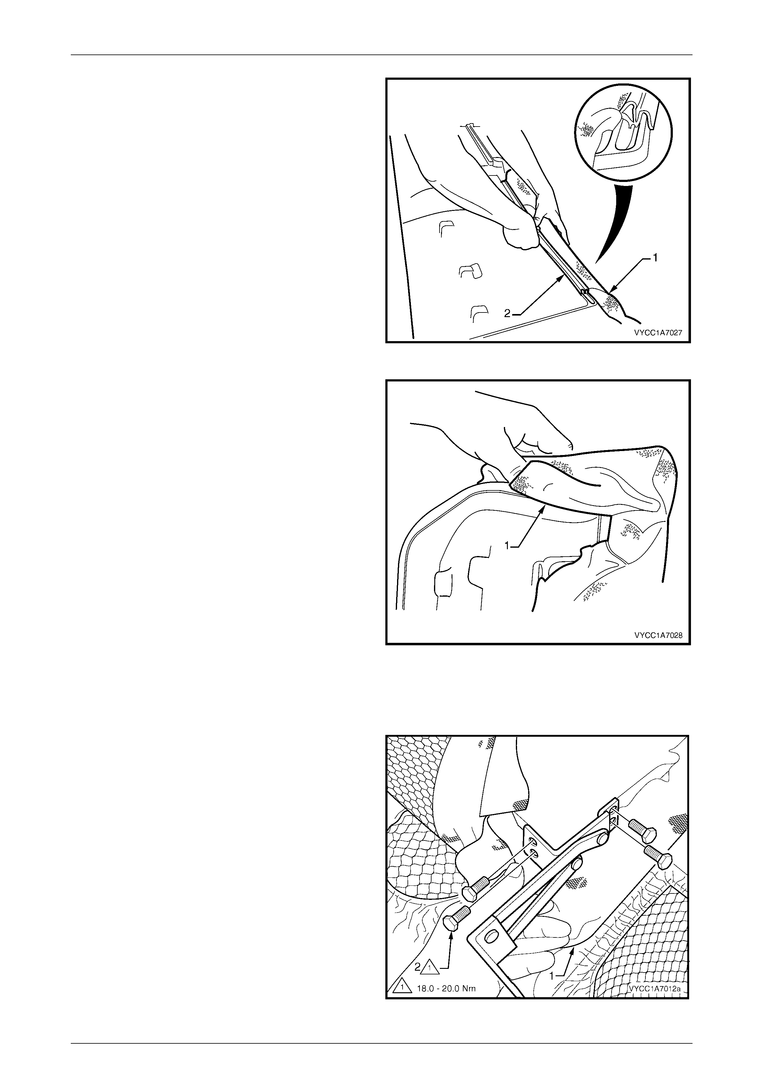
1 Remove the screw (1), two places, attaching the rear
seat latch and latch cover (2) to the seat cushion
base (3).
2 Unhook the latch release rod from the latch.
3 Lift the latch clear of the release button.
Figure 1A7 – 28
Reinstall
Reinstallation of the rear seat latch is the reverse of the removal process noting the following:
1 Locate the release rod in the latch fully.
2 Tighten the attaching screws to the correct torque specification.
Rear seat cushion latch attaching screw
torque specification ................................ 12.0 – 15.0 Nm
3 Check that the release button and latch operate smoothly.
Seat Assemblies Page 1A7–26
Page 1A7–26
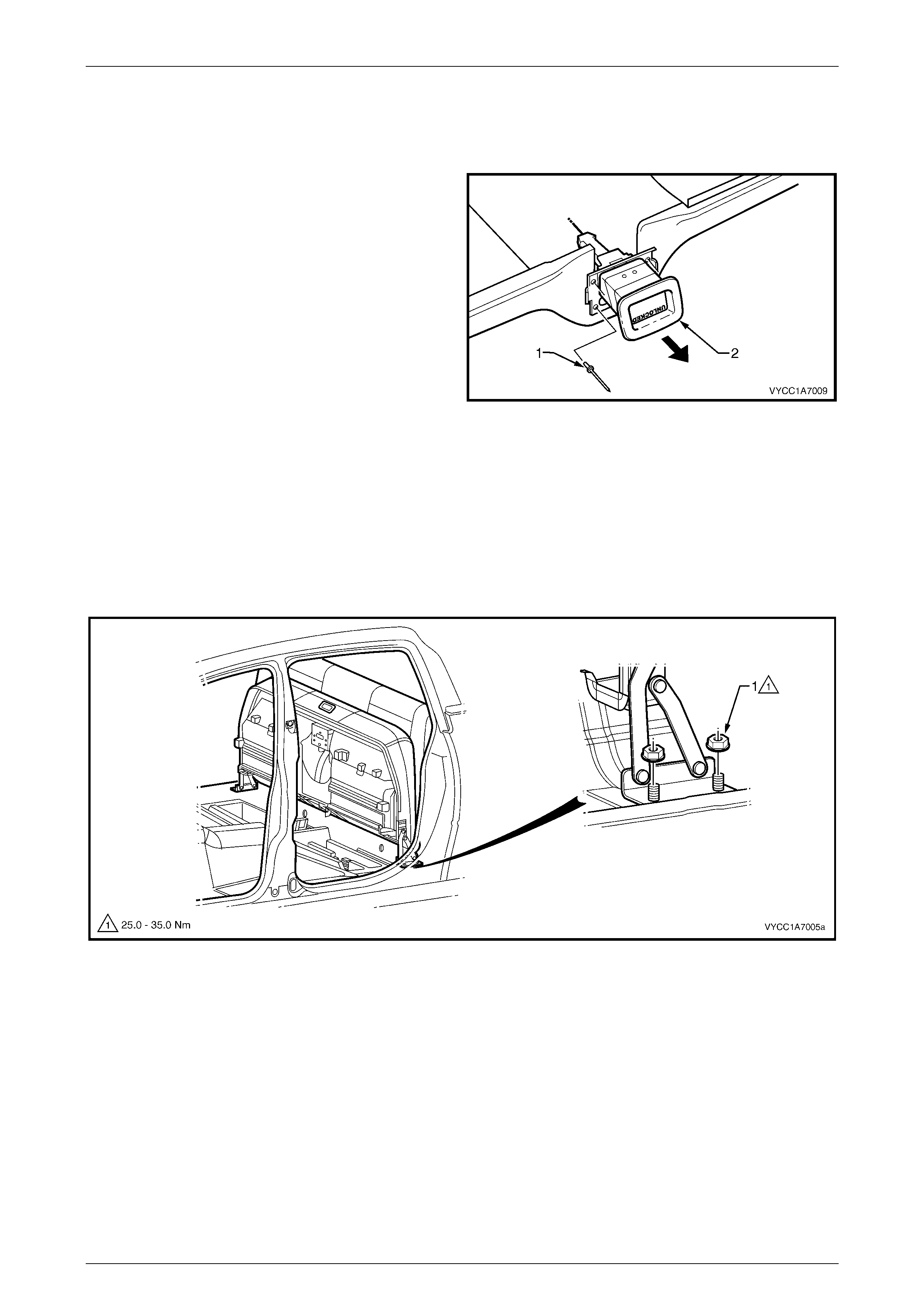
Rear Seat Release Button
Remove
1 Remove the pop rivets (1), four places, attaching the
rear seat cushion release button (2) to the rear seat
cushion base by drilling the heads off the rivets.
2 Remove the release button from the rear seat cushion
base.
Figure 1A7 – 29
Reinstall
Reinstallation of the rear seat release button is the reverse of the removal process. Secure with new pop rivets.
Reinstall
Reinstallation of the rear seat cushion assembly is the reverse of the removal process noting the following:
1 Ensure the rear seat assembly is in the upright position and the hinge is horizontal, refer to Figure 1A7 – 30.
Figure 1A7 – 30
Seat Assemblies Page 1A7–27
Page 1A7–27
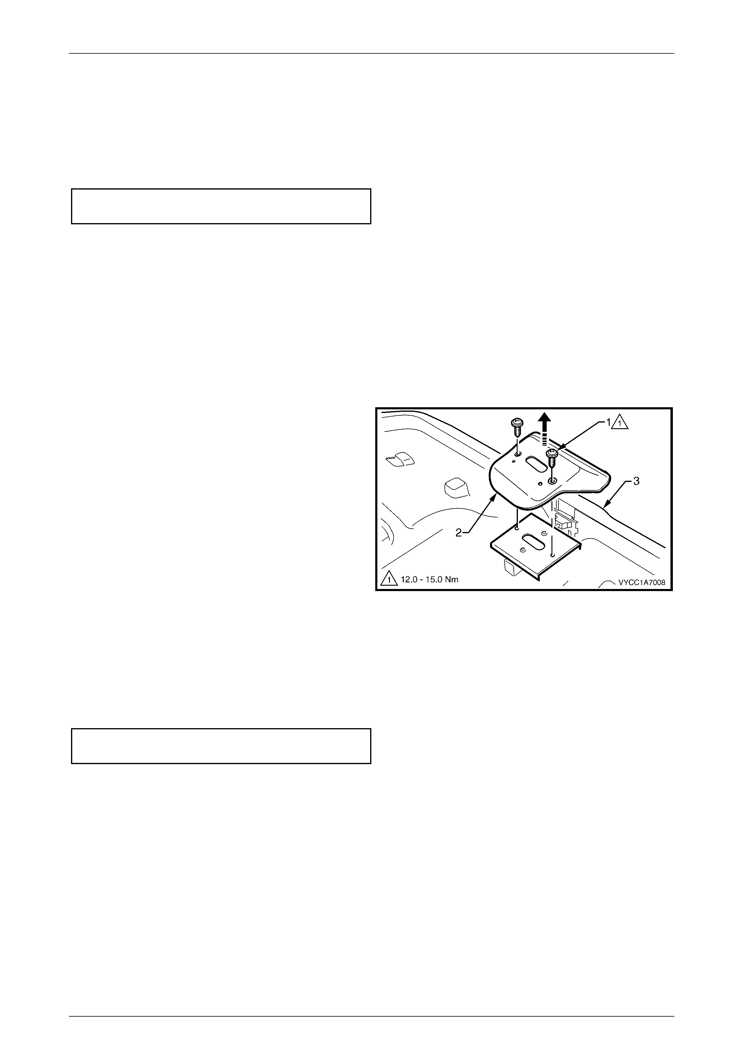
2 Initially tighten the attaching nuts and ensure the
design lines (1) match up to within 10mm when
measured in a lateral direction, readjust if required, by
loosening the attaching nuts and repositioning.
3 Install the nut (1), two places each side, and tighten to
the correct torque specification.
Rear seat hinge attaching nut
torque specification ................................ 25.0 – 35.0 Nm
Figure 1A7 – 31
Seat Assemblies Page 1A7–28
Page 1A7–28
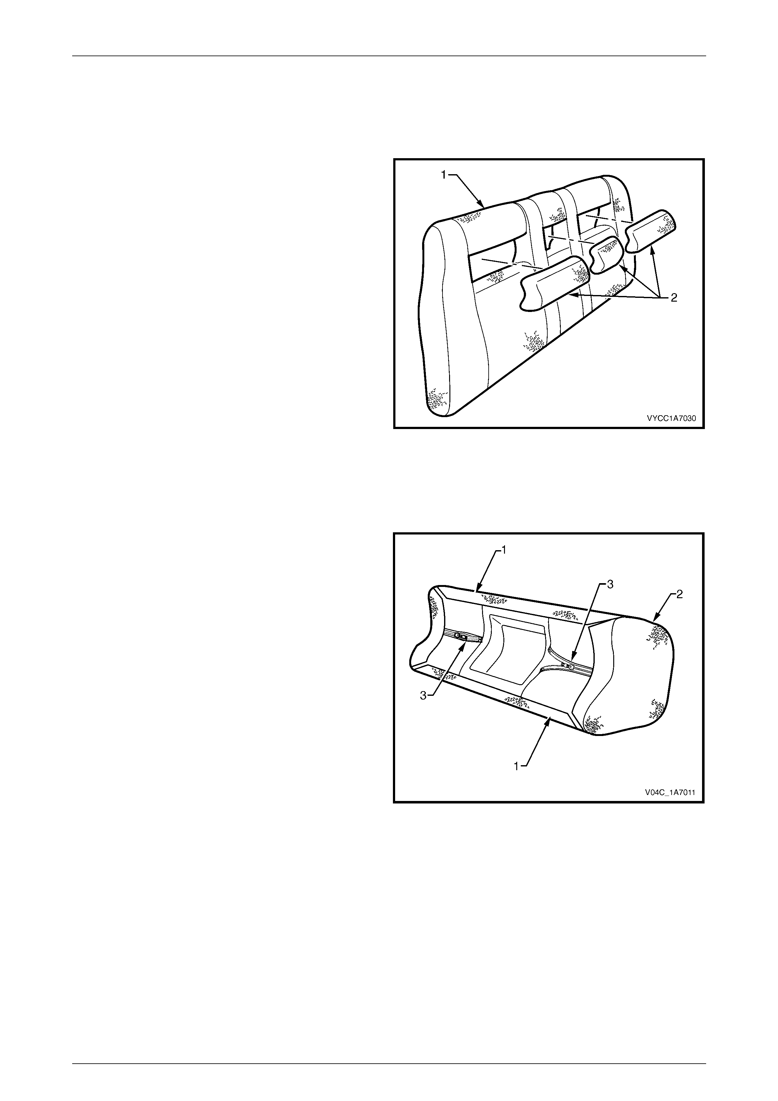
4.3 Rear Seat-back Insert
Remove
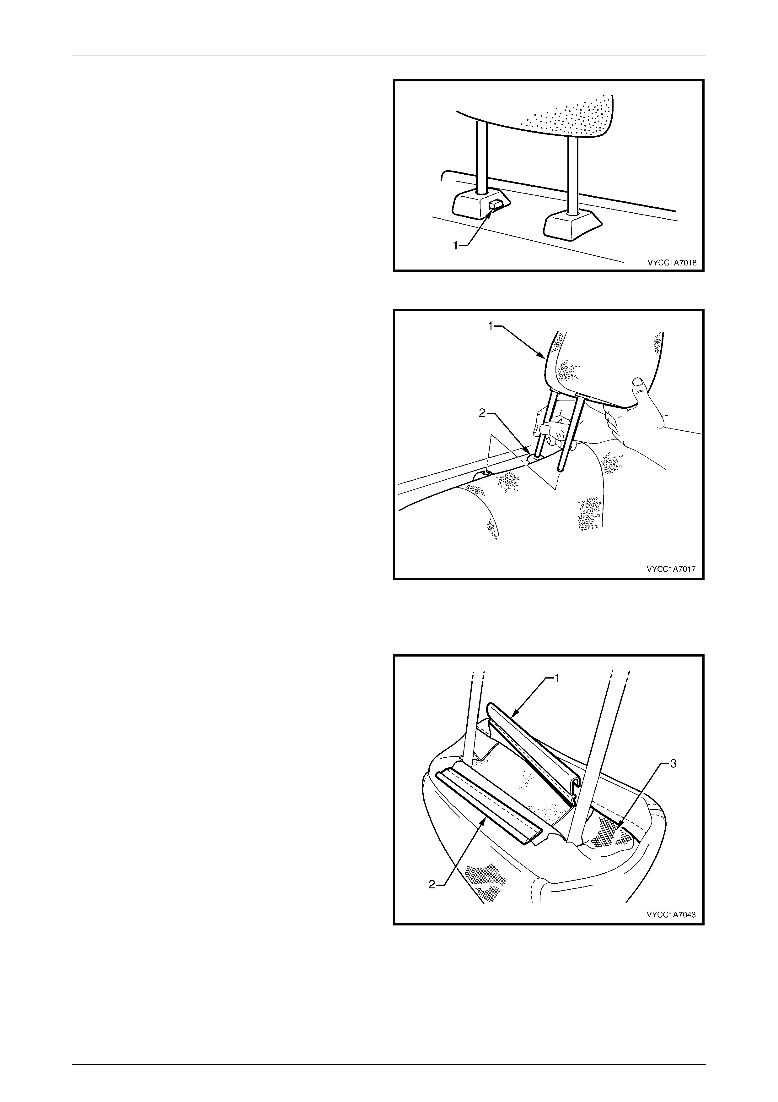
1 Holding the rear seat-back assembly (1), place your
hand over the top of the insert (2) and pull the rear
seat-back insert out towards the front of the rear seat-
back assembly.
Figure 1A7 – 32
Disassemble
Outer Insert
1 Peel back the two hook and loop strips (1), attaching
the cover (2) to the pad.
2 Remove the two zip fasteners (3).
3 Starting from one corner, carefully remove the cover
from the pad.
Figure 1A7 – 33
Seat Assemblies Page 1A7–29
Page 1A7–29
Inner Insert
1 Pull the zip fastener (1) back slightly to allow access to
the tag (2) on the fastener.
2 Unzip the cover completely .
3 Starting from one corner, carefully remove the cover
from the pad.
Figure 1A7 – 34
Reassemble
Reassembly of the rear seat-back inner and outer insert cover is the reverse of the removal process, noting the following:
1 Ensure the cover is fitted neatly by hand without any creases and the hook and loop strips on the outer insert are
sitting flat against the pad and are fully fastened.
2 Ensure the centre insert zip fastener is fully closed and the tag is tucked in underneath the insert cover, refer Figure
1A7 – 34.
NOTE
As part of their designed appearance, leather
cushion covers have inherent minor creases in
the material.
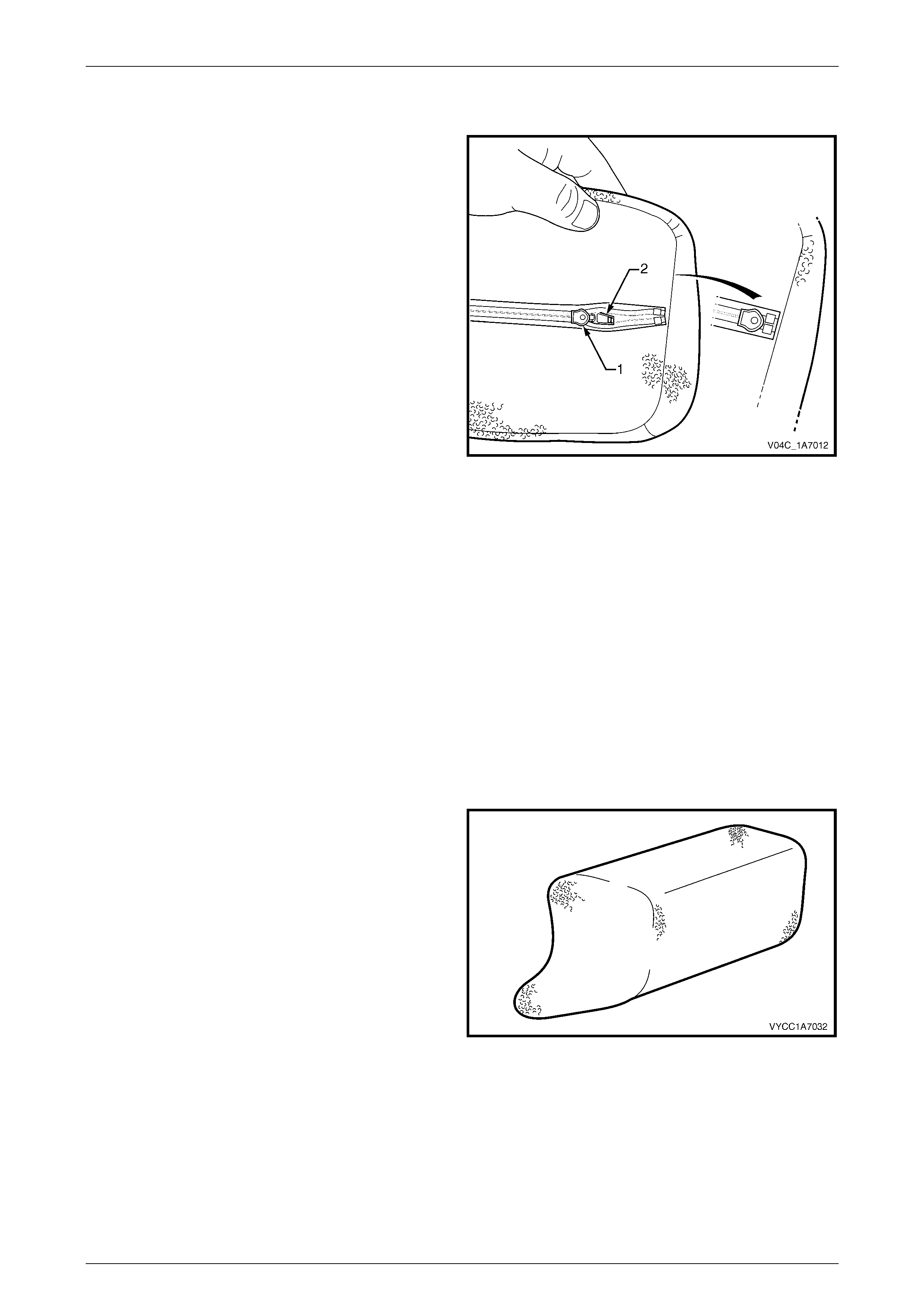
Reinstall
Reinstall atio n of the rear seat- bac k insert is the rev erse of
the removal procedure ensuring the wider section is facing
towards the bottom of the seat-back assembly.
Figure 1A7 – 35
Seat Assemblies Page 1A7–30
Page 1A7–30
4.4 Rear Seat-back Assembly
LT Section No. – 14-350
If required, remove the following:
1 Rear seat cushion assembly, refer to 4.2 Rear Seat Cushion Assembly.
2 Rear seatbelts, refer to Section 12M, 2.1 Rear Seatbelt Assembly.
Remove
1 If required, raise the head restraints to the upper stop, refer to 4.5 Head Restraint Assembly.
2 Remove the bolt (1), two places, attaching the rear seat-back assembly (2) to the body, refer to Figure 1A7 – 36.
Figure 1A7 – 36
3 Holding the rear seat-back assembly at the lower edge, carefully raise the assembly evenly until the upper
attaching hook (View A), three places, are released.
4 Remove the rear seat-back assembly through the rear door opening.
Disassemble
Rear Seat-b ack Cov er
Remove
1 If required, remove the rear seat-back inserts, refer to 4.3 Rear Seat-back Inserts.
2 Remove the two rear seat-back insert opening covers
(1), by carefully pulling the cover away from the seat-
back assembly, releasing the eight hook and loop
strips (2).
Figure 1A7 – 37
Seat Assemblies Page 1A7–31
Page 1A7–31
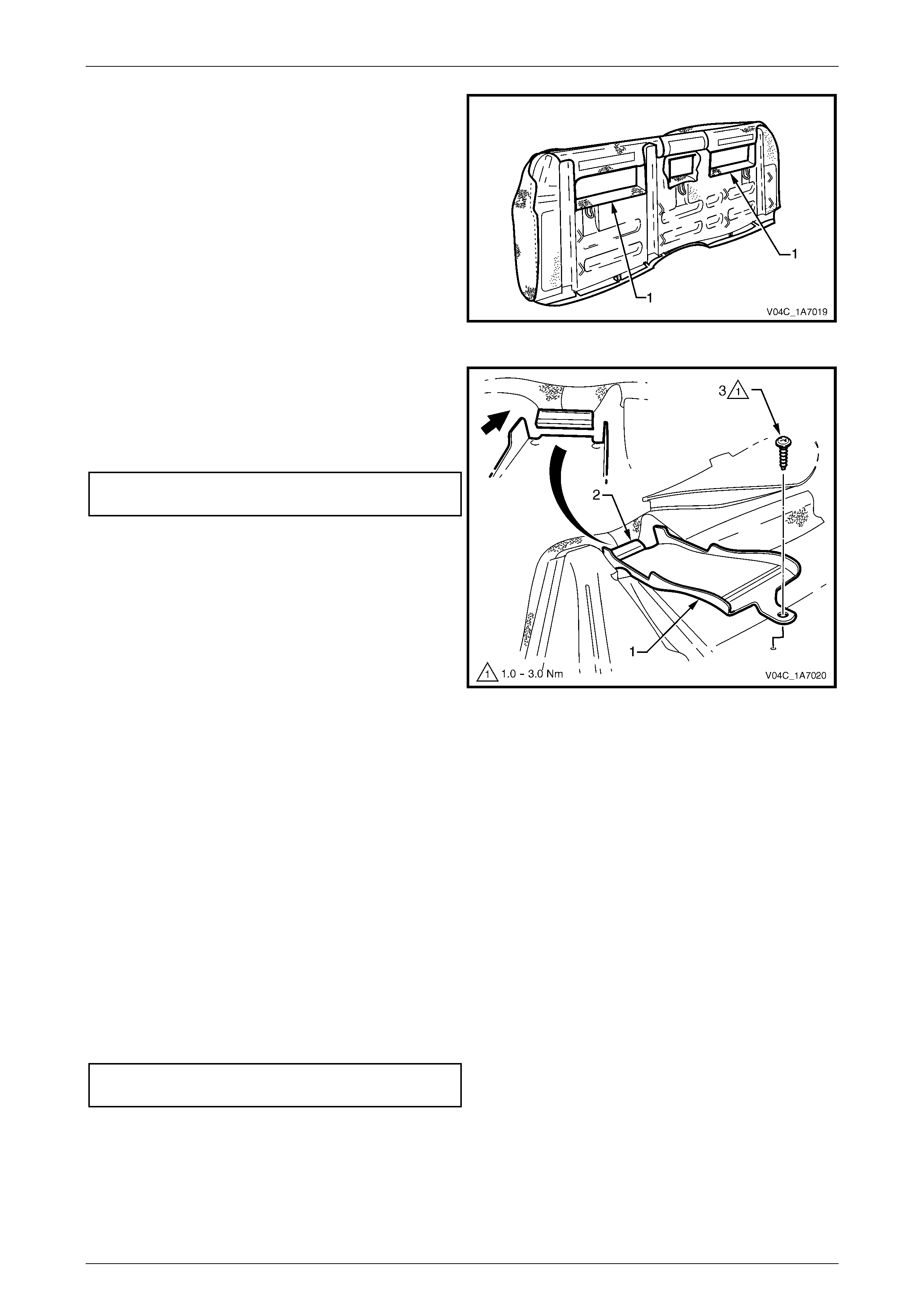
3 Remove the screw (1), attaching the seatbelt guide
(2), to the rear seat-back assembly and remove the
guide by sliding it out from under the J-strip (3).
4 Repeat step 3 for the two remaining seatbelt guides.
Figure 1A7 – 38
5 Remove the five hook and loop strips (1) and the four
hook and loop strips around the centre insert cavity
(2).
Figure 1A7 – 39
6 Fold back the two rear seat-back rear covers (1).
Figure 1A7 – 40
Seat Assemblies Page 1A7–32
Page 1A7–32
7 Remove the J-strips (1), 12 places, attaching the rear
seat-back cover to the seat-back frame, by raising the
J-strip slightly and pushing toward the centre of the
rear seat-back assembly.
8 Carefully fold the cover over the corners of the rear
seat-back cushion pad.
Figure 1A7 – 41
9 Starting at the corner of the rear seat-back pad
assembly (1), carefully pull the cushion cover (2),
releasing the hook and loop strips (3).
Figure 1A7 – 42
10 Continue removing the cover, releasing all hook and
loop strips (1) from the pad (2) until the cover is
removed.
Figure 1A7 – 43
Seat Assemblies Page 1A7–33
Page 1A7–33
Reinstall
1 Align the rear seat-back cushion cover to the pad and
push the cover in to the groove, engaging the hook
and loop strips (1).
Figure 1A7 – 44
2 Working along the rear seat-back pad (1) continue
inserting the cover (2) into the corresponding grooves
aligning the hook and loop strips (3).
Figure 1A7 – 45
3 Place the rear seat-back assembly face down on a clean surface.
4 Fold and position the cover neatly over the corners of the rear seat-back cushion pad.
5 Reinstall the 12 J-strips by raising the J-strip slightly then clipping it onto the frame, refer to Figure 1A7 – 41.
6 Fold the right-hand rear seat-back rear cover (1) over
the back of the seat-back assembly and fasten the
lower hook and loop strip (2).
7 Fold the Left-hand rear seat-back rear cover (3) over
the seat-back assembly and fasten the hook and loop
strip (4) in the insert cavity.
NOTE
Ensure the rear seat-back rear covers are sitting
flat and free from any creases. Realign the hook
and loop strips if necess ary .
Figure 1A7 – 46
Seat Assemblies Page 1A7–34
Page 1A7–34
8 Reattach the hook and loop strips (1), four places
around the rear seat-back insert cavities.
Figure 1A7 – 47
9 Reinstall the seatbelt guide (1) by gently pushing the
seatbelt guide into the groove in the rear seat-back
pad under the J-strip (2).
10 Tighten the attaching screw (3) to the correct torque
specification.
Seatbelt guide attaching screw
torque specific atio n .................................... 1.0 – 3.0 Nm
11 Repeat steps 9 and 10 for the two remaining seatbelt
guides.
Figure 1A7 – 48
12 Reinstall the two rear seat-back insert opening covers ensuring the flap in cover for the child restraint anchor in the
centre of the rear seat-back insert cavity, refer to Figure 1A7 – 37.
NOTE
Ensure the cushion cover is fitted neatly by hand
into all corners and grooves and is free from any
creases. As part of their designed appearance,
leather cushion covers have inherent minor
creases in the material.
Reinstall
Reinstallation of the rear seat-back assembly is the reverse of the removal process noting the following:
1 Ensure the two, rear seat-back insert opening covers align with the child restraint anchor.
2 Ensure the upper attaching hooks (View A) lock into place and the lower attaching bolts (1), are tightened to the
correct torque specification, refer to Figure 1A7 – 36.
Rear seat-back assembly attaching bolt
torque specification ................................ 25.0 – 35.0 Nm
3 If required, reinstall the rear seatbelts, refer to Section 12M, 2.1 Rear Seatbelt Assembly.
4 Reinstall the rear seat cushion assembly, refer to 4.2 Rear Seat Cushion Assembly.
Seat Assemblies Page 1A7–35
Page 1A7–35
4.5 Head Restraint Assembly
LT Section No. – 14-350
Remove
NOTE
Although the rear seat-back centre head restraint
is different in appearance than the outer head
restraints, the same service procedures apply for
both.
If required, remove the rear seat-back assembly, refer to 4.4 Rear Seat-Back Assembly.
1 Raise the head restraint fully.
Figure 1A7 – 49
2 Insert a suitable size probe into the hole (1) in the
left-hand head restraint guide (2).
3 Push the probe in slightly while applying slight upward
pressure on the head restraint. Hold the upward
pressure.
Figure 1A7 – 50
Seat Assemblies Page 1A7–36
Page 1A7–36
4 Depress the right-hand head restraint sleeve height
adjuster lock (1) and raise the head restraint so that
the right-hand head restraint post is clear of the
sleeve.
Figure 1A7 – 51
5 Remove the head restraint from the right-hand sleeve
and rotate the head restraint (1).
6 Remove the head restraint from the left-hand head
restraint sleeve (2).
NOTE
The right-hand head restraint post has a reduced
height to assist in the removal and reinstallation
of the head restraint.
Figure 1A7 – 52
Disassemble
1 Disengage the front head restraint cover J-strip by
pulling the flap (1) back and out of flap (2) in the
direction shown.
2 Beginning at one corner of the head restraint, gently
remove the cover from the p ad assembly.
Figure 1A7 – 53

Seat Assemblies Page 1A7–37
Page 1A7–37
Reassemble
Reassembly of the front seat head restraint assembly is the reverse of the removal procedure, ensuring the head
restraint cover J-clips are fully engaged and the cover (3) is tucked neatly into the corners, refer Figure 1A7 – 53.
NOTE
Ensure the head restraint cover is fitted neatly by
hand and is free from any creases. As part of
their designed appearance, leather cushion
covers have inherent minor creases in the
material.
Reinstall
Reinstallation of the rear head restraint is the reverse of the removal procedure.
Seat Assemblies Page 1A7–38
Page 1A7–38
4.6 Head Restraint Sleeve
LT Section No. – 14-350
Remove
1 If required, remove the head restraint, refer to 4.5 Head Restraint Assembly.
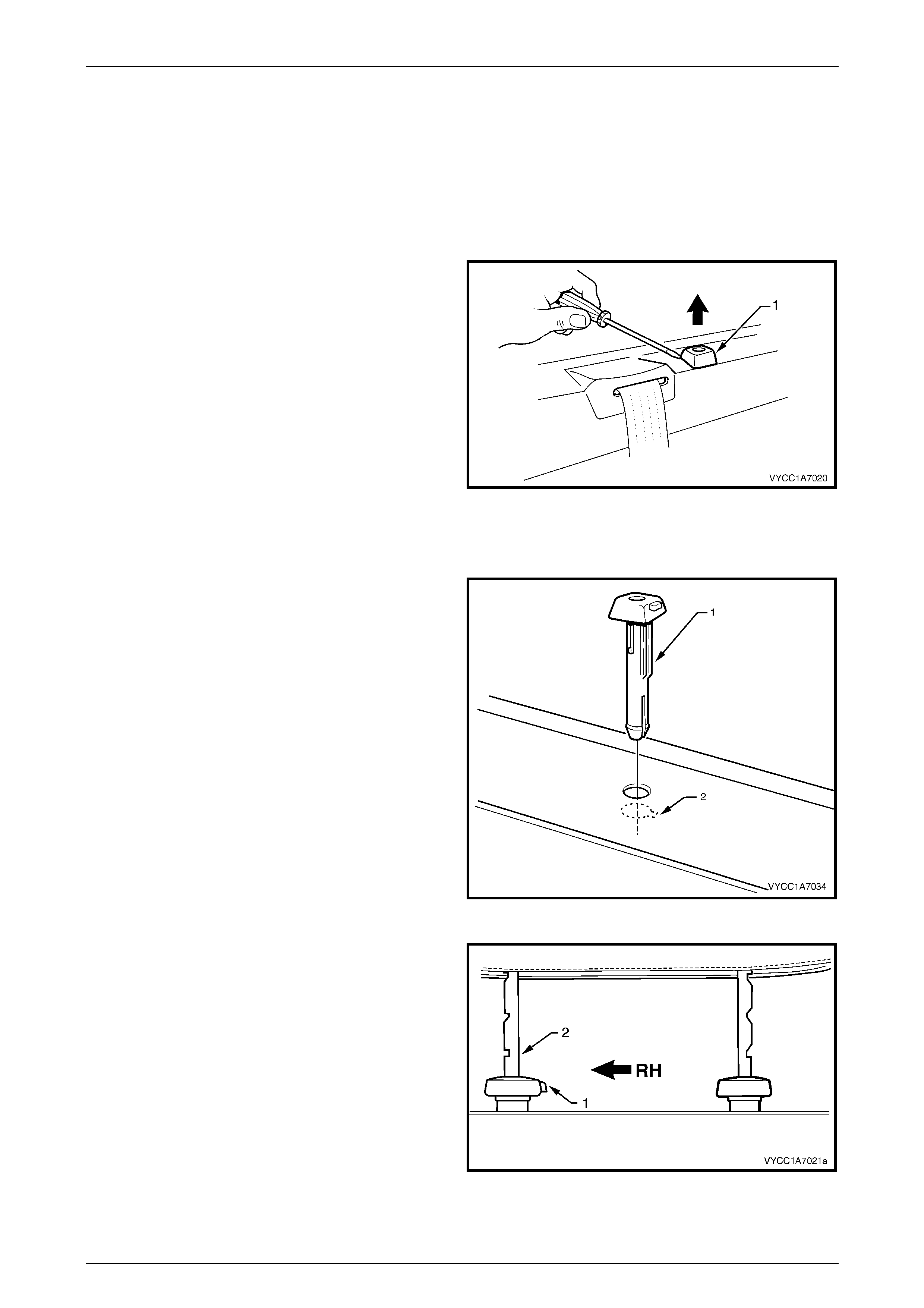
2 Using a suitable sized screwdriver, gently lever the
head restraint sleeve up while applying a slight upward
pressure.
3 Remove the head restraint sleeve form the upper
cross beam cover and pane l.
Figure 1A7 – 54
Reinstall
1 Align the head restraint sleeve ensuring the locating
ribs (1) of the head restraint sleeve aligns with the key-
way (2) in the upper cross beam cover, then insert the
sleeve into the rear cross beam panel until it clips into
place.
NOTE
The head restraint sleeve shown is the
right-hand side. When viewed from inside of the
vehicle the release button in the right-hand and
the hole in the left-hand side should face each
other when installed correctly.
Figure 1A7 – 55
2 Ensure the sleeve with the height adjuster lock (1) is
installed on the right-hand side of the upper
cross-beam cover when viewed from the front of the
vehicle; that is the side that corresponds to the lower
square notch (2) in the head restraint shaft.
3 Reinstall the rear head restraint, refer to
4.5 Head Restraint Assembly.
Figure 1A7 – 56

Seat Assemblies Page 1A7–39
Page 1A7–39
5 Torque Wrench Specifications
Rear Seat Cushion Hinge Attaching Bolt...................................18.0 – 20.0 Nm
Rear Seat Cushion Latch Attaching Screw................................12.0 – 15.0 Nm
Rear Seat Cushion Hinge Attaching Nut....................................25.0 – 35.0 Nm
Rear Seatbelt Guide Attaching Screw............................................1.0 – 3.0 Nm
Rear Seat-back Assembly Attaching Bolt..................................25.0 – 35.0 Nm