
Headlining and Int eri or Tri m Page 1A8–1
Page 1A8–1
Section 1A8
Headlining and Interior Trim
ATTENTION
Before performing any Service Operation or other procedure described in this Section, refer to Section 00
Warnings, Cautions and Notes for correct workshop practices w ith regard to safety and/or property damage.
1. General Information............................................................................................................................... 2
2 Service Operations................................................................................................................................ 3
2.1 Pictorial Index .........................................................................................................................................................3
2.2 Rocker Panel Cover Extension.............................................................................................................................4
Remove ...................................................................................................................................................................4
Reinstall..................................................................................................................................................................4
2.3 Jack Box .................................................................................................................................................................5
Remove ...................................................................................................................................................................5
Reinstall..................................................................................................................................................................6
2.4 Body Lock Pillar Trim Assembly...........................................................................................................................7
Remove ...................................................................................................................................................................7
Reinstall..................................................................................................................................................................7
2.5 Upper Cross-Beam Cover......................................................................................................................................8
Remove ...................................................................................................................................................................8
Reinstall..................................................................................................................................................................8
2.6 Headlining...............................................................................................................................................................9
Remove ...................................................................................................................................................................9
Reinstall................................................................................................................................................................10
2.7 Carpet Assembly..................................................................................................................................................11
Remove .................................................................................................................................................................11
Reinstall................................................................................................................................................................12
3 Trim Clearances................................................................................................................................... 13
4 Torque Specifications ......................................................................................................................... 14

Headlining and Int eri or Tri m Page 1A8–2
Page 1A8–2
1. General Information
With the following exceptions, MY 2004 VY Regular Cab and Crew Cab headlining and interior trim information carries
over from MY 2004 VY Series vehicles and MY 2003 VY Regular Cab vehicles.
Crew Cab:
• Inner rear panel storage pockets
• Inner rear panel carpet
• Rocker panel cover extensions
• Upper cross-beam cover
• Headlining
• Body lock pillar trim assembly
• Carpet assembly
• Jack box
For information not contained within this Section, refer to Section 1A8 Headlining and Interior Trim in the MY 2004 VY
and V2 Series Service Information and Section 1A8 Headlining and Interior Trim in the MY 2003 VY Regular Cab
Service Information.
To further assist in the identification of the interior trim and headlining components and the correct service procedure
location, refer to the appropriate pictorial index diagrams and reference charts.
Jack boxes are fitted on each side of the vehicle, under the rear seat. These boxes form part of the vehicles safety
structure and must be fitted using the correct fasteners and sealers to ensure that the structural integrity of the vehicle is
maintained.
When working on the body interior trim, clean hands are essential and a protective covering must be placed over the
interior trim.

Headlining and Int eri or Tri m Page 1A8–3
Page 1A8–3
2 Service Operations
2.1 Pictorial Index
Figure 1A8 – 1
1 Headlining
2 Centre Pillar Upper Trim, refer to Section 1A8, 3.3 Centre
Pillar Upper Trim in t he MY 2004 V Y and V2 Series Service
Information.
3 Body Lock Pillar Trim Assembly
4 Window Side Garnish, ref er to Section 1A8 Headl i n i ng and
Interior Tri m in the MY 2004 VY and V2 Series Service
Information.
5 Centre Pillar Lower Trim, ref er to Section 1A8 Headlining
and Interior Tri m in the MY 2004 VY and V2 Series Service
Information.
6 Upper Cross-beam Cover
7 Side Sill Trim, refer to Sect ion 1A 8 Headlining and Interior
Trim i n the MY 2004 VY and V2 Series Service Inf ormation
8 Rocker P anel E xtens i ons
9 Hinge Pillar Trim, refer to Section 1A8 Headlining and
Interior Tri m in the MY 2004 VY and V2 Series Service
Information.
10 Jack Boxes
11 Floor Carpet
Headlining and Int eri or Tri m Page 1A8–4
Page 1A8–4
2.2 Rocker Panel Cover Extension
Remove
1 Raise the rear seat, refer to Section 1A7, 4.2 Rear Seat Cushion Assembly.
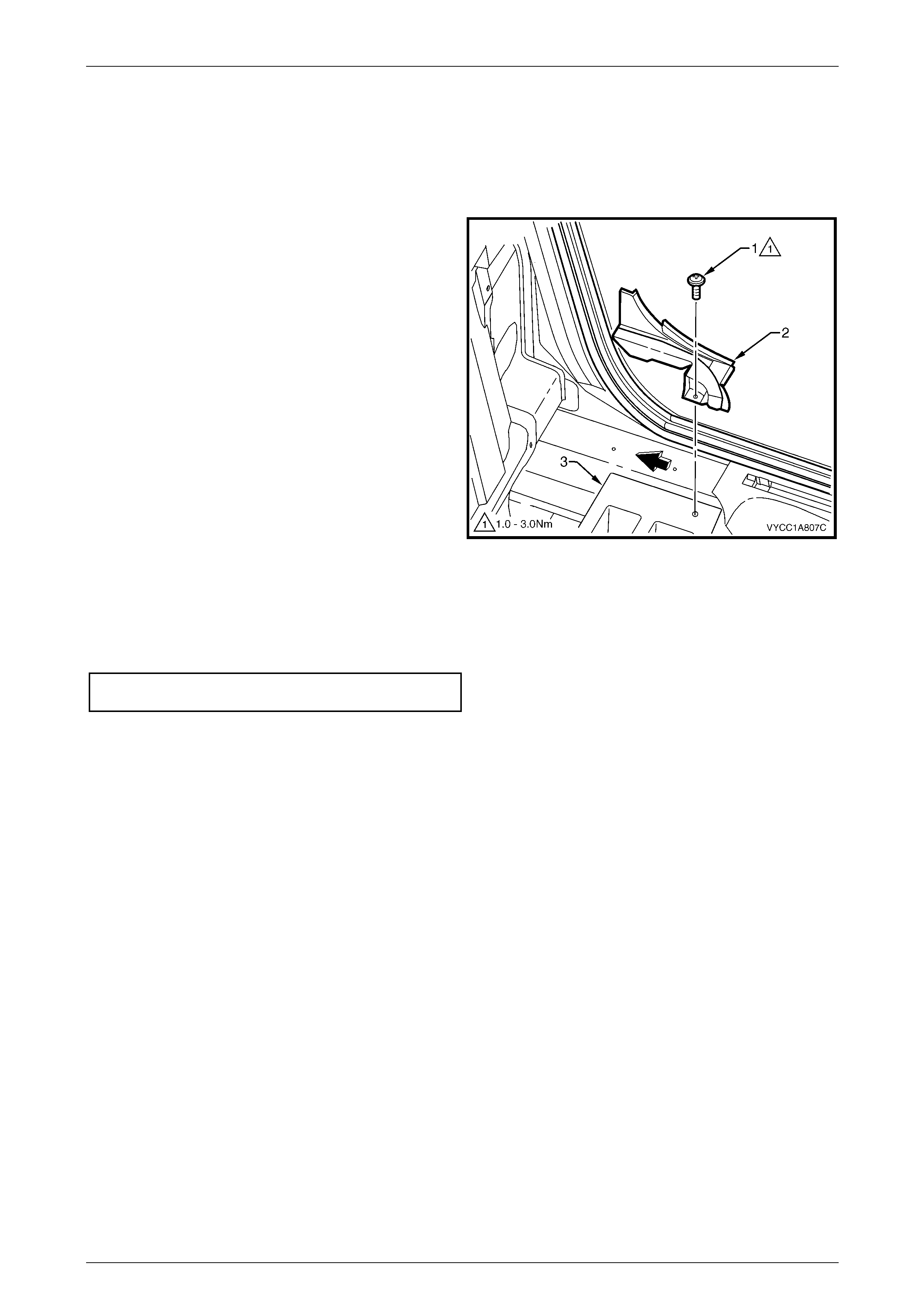
2 Remove the screw (1) securing the rocker panel cover
extension (2) to the jack box (3).
3 Partially, remove the doorframe weather strip.
4 Remove the rocker panel cover extension by sliding it
towards the rear of the vehicle, raising the front and
pulling it forward.
Figure 1A8 – 2
Reinstall
Reinstallation of the rocker panel cover extension is the reverse of the removal process. Ensure the rocker panel cover
extension sits against the doorframe weather strip and the screw is tightened to the specified torque.
Rocker panel extension screw
torque specification....................................1.0 – 3.0 Nm
Headlining and Int eri or Tri m Page 1A8–5
Page 1A8–5
2.3 Jack Box
The jack box form part of the vehicle's safety
structure and must be installed correctly
using the correct fasteners, sealers and
screw torques. The jack box is not to be
cleaned with solvents and if damaged, they
must be replaced. Ensure the jack and brace
is secured correctly in the left-hand side jack
box as per the owners manual.
Remove
1 Remove the rear seat cushion, refer to Section 1A7, 4.2 Rear Seat Cushion Assembly.
2 Remove the rocker panel cover extension, refer 2.2 Rocker Panel Cover Extension.
3 Remove the seatbelt retractors, refer to Section 12M, Occupant Protection System.
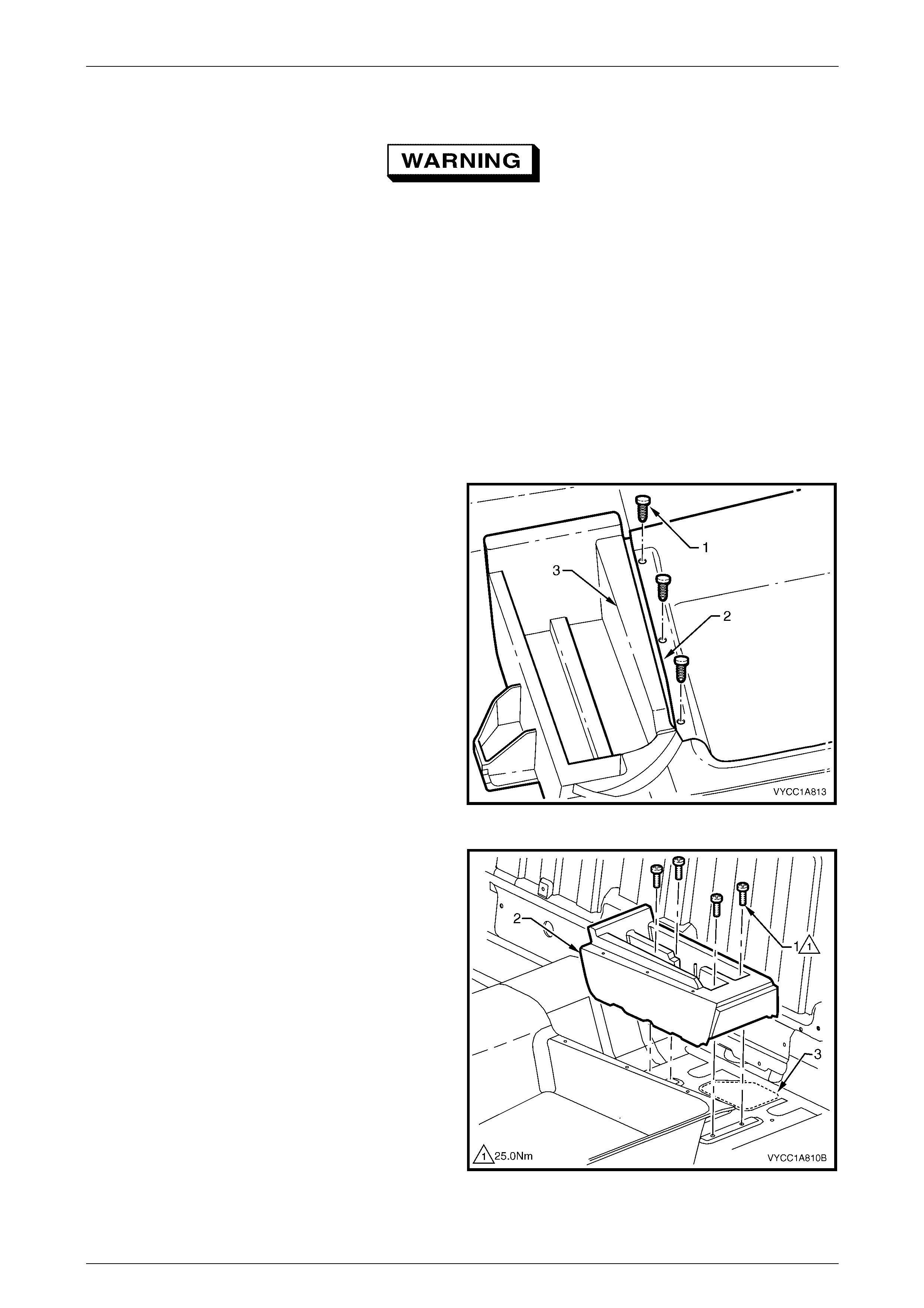
4 Remove the fastener (1), three places, attaching the
rear section of the carpet (2) to the jack box and peel
the carpet back slightly.
Figure 1A8 – 3
5 Remove the Torx head screw (1), four places, in the
base of the jack box (2).
NOTE
A bead of mastic sealer is applied around the
rear of the jack box to seal the carriage hole (3)
in the floor pan. This may require some effort to
release the bond from the sealer.
6 Lift the jack box slightly and slide it towards the rear of
the vehicle, then lift it up to remove.
Figure 1A8 – 4
Headlining and Int eri or Tri m Page 1A8–6
Page 1A8–6
Reinstall
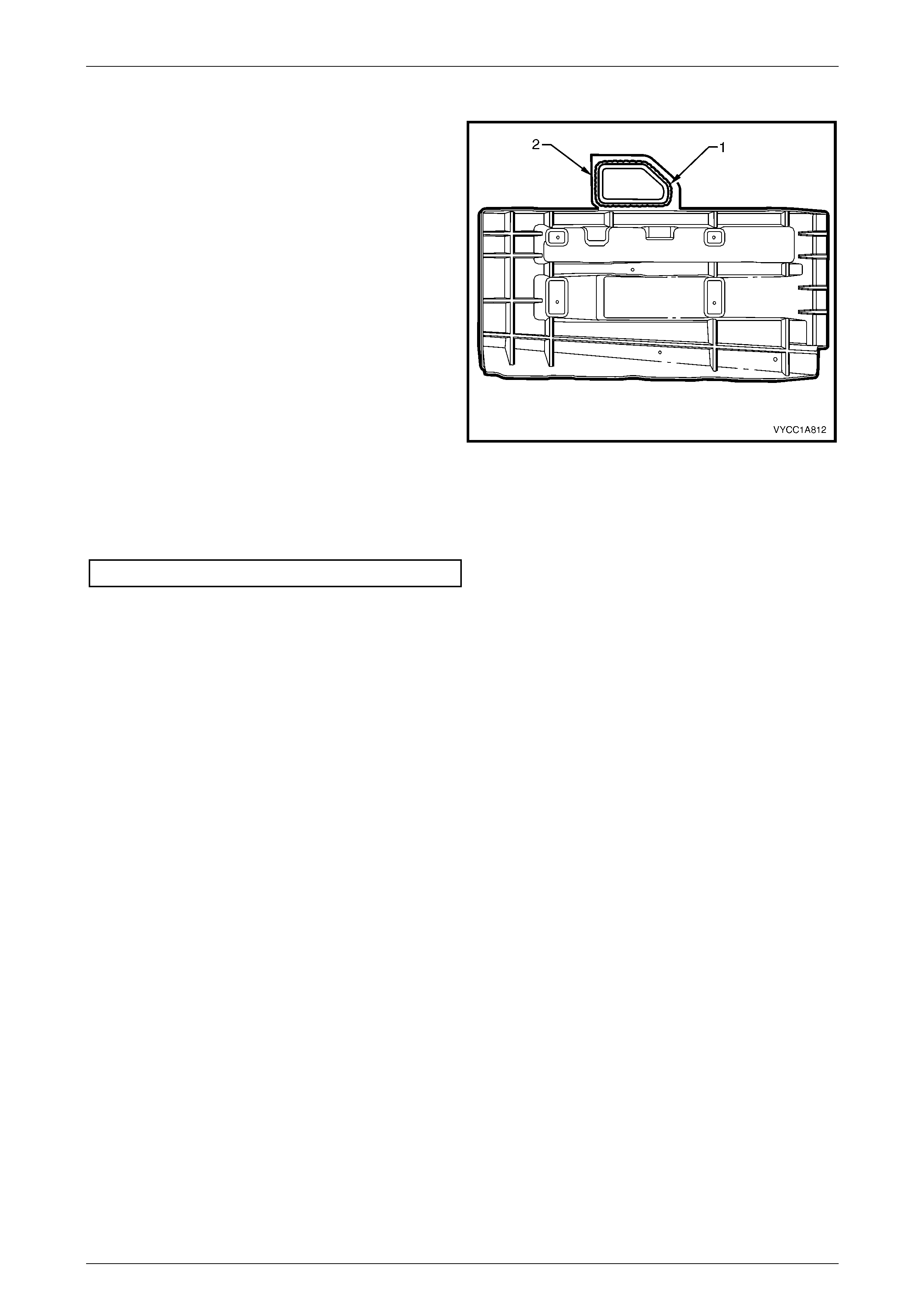
1 Apply a bead of mastic sealer or similar (1) to the jack
box (2) in the location shown.
Figure 1A8 – 5
2 While holding the rear section of the jack box up slightly to avoid sealer contact, slide the jack box forward into
position.
3 Install the four Torx head screws (1), refer to Figure 1A8 – 4 and tighten to the specified torque.
Jack box screw torque specification................. 25.0 Nm
4 Refit the seatbelt retractors, refer to Section 12M, Occupant Protection System.
5 Refit the rocker panel extension cover, refer to 2.2 Rocker Panel Cover Extension.
6 Refit the fasteners (1), three places securing the rear section of the carpet, refer to Figure 1A8 – 3.
7 Refit the rear seat cushion, refer to Section 1A7, 4.2 Rear Seat Cushion Assembly.
Headlining and Int eri or Tri m Page 1A8–7
Page 1A8–7
2.4 Body Lock Pillar Trim Assembly
Remove
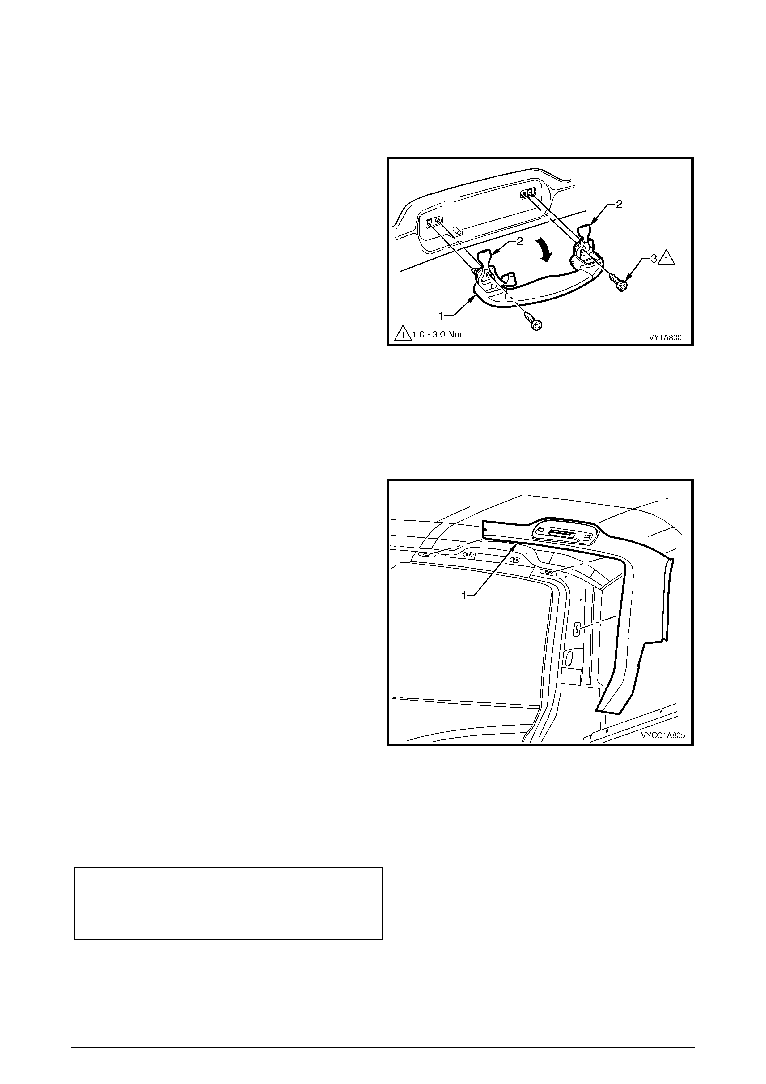
1 Pull the assist handle (1) into the down position.
2 Prise open the assist handle screw cover (2) and
remove the attaching screw (3), two places.
3 Remove the assist handle ensuring care is taken not
to damage the locating pins.
Figure 1A8 – 6
4 If fitted, remove the roof rail courtesy lamp, refer to Section 12B, Roof Rail Courtesy and Reading Lamp Assembly
in the MY 2003 VY and V2 Series Service Information.
5 Partially remove the centre pillar upper trim by removing the upper attaching screw, refer to Section 1A8
Headlining and Interior Trim in the MY 2004 VY and V2 Series Service Information.
6 Remove the rear seat-back assembly, refer to Section 1A7, 4.4 Rear Seat-back Assembly.
7 Beginning at the front of the body lock pillar trim (1),
carefully remove the trim by carefully pulling it away
from the body to release three clips.
Figure 1A8 – 7
Reinstall
Reinstallation of the body lock pillar upper trim is the reverse of the removal, noting the following:
1 Tighten all fasteners to the specified torque.
Body lock pillar trim screw
torque specification.....................................1.0 - 3.0 Nm
Assist handle screw
torque specification.....................................1.0 - 3.0 Nm
Headlining and Int eri or Tri m Page 1A8–8
Page 1A8–8
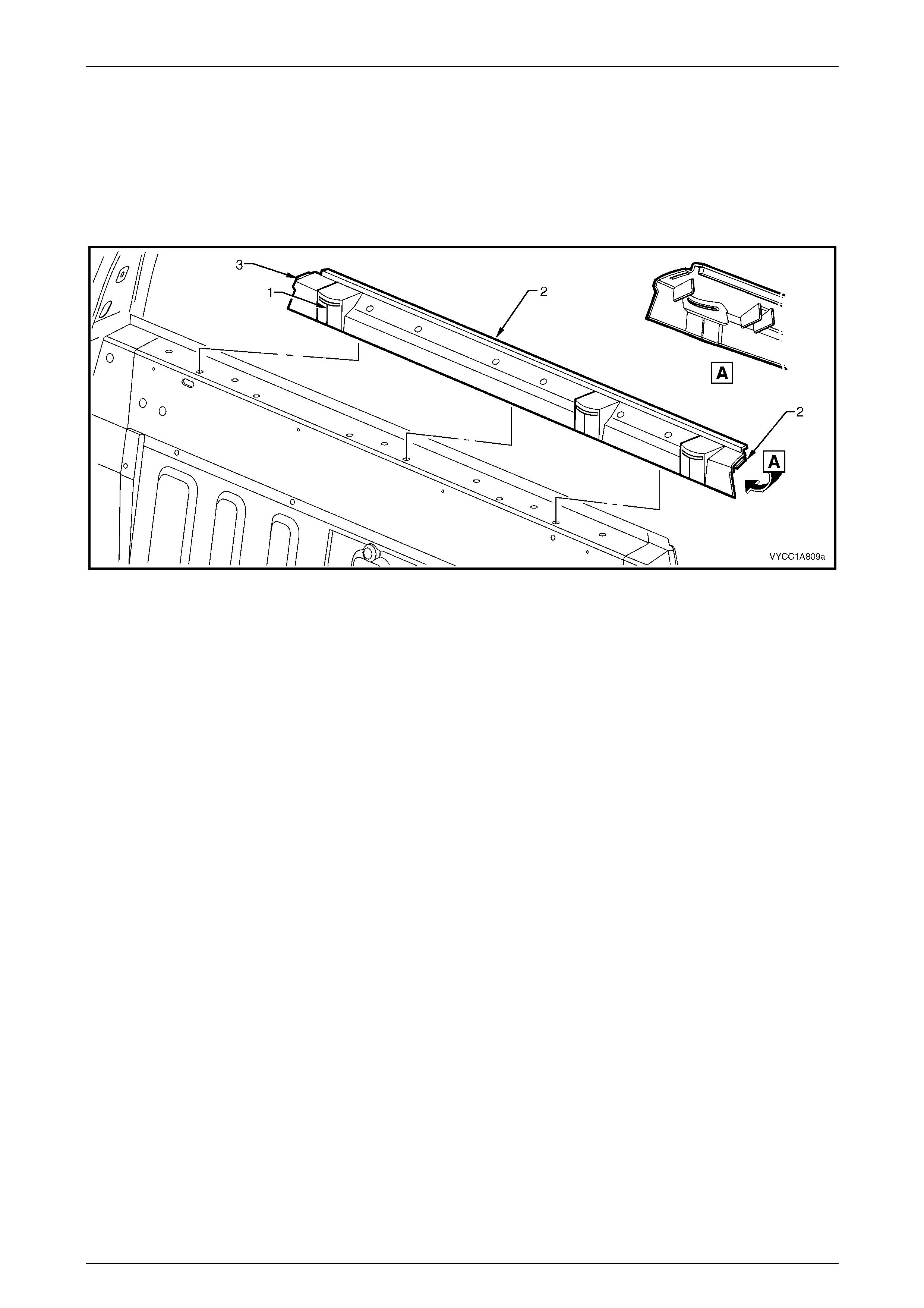
2.5 Upper Cross-Beam Cover
Remove
1 Remove the rear seat back head restraint sleeves, refer to Section 1A7, 4.6 Head Restraint Sleeves.
2 Remove the body lock pillar trim assembly, refer to 2.4 Body Lock Pillar Trim Assembly.
Figure 1A8 – 8
3 Manoeuvre the seat belt webbing through the slot (1), three places in the upper cross-beam cover (2).
4 Lift the upper cross-beam cover from the rear panel and remove.
Reinstall
Reinstallation of the upper cross-beam cover is the reverse of the removal procedure. Ensure that the seat belts are not
twisted through the cover and the locating tabs (3) engage in the body lock pillar trim.
Headlining and Int eri or Tri m Page 1A8–9
Page 1A8–9
2.6 Headlining
Remove
As required remove the following:
1 Remove the fuse F6 from the passenger compartment fuse and relay assembly, refer to Section 12O Fuses,
Relays and Wiring Harnesses in the MY 2004 VY and V2 Series Service Information.
2 Remove the rear seat-back assembly, refer to Section 1A7, 4.4 Rear Seat-back Assembly.
3 Place a protective covering over both front seats and the interior trim.
4 Partially remove the centre pillar upper trim, refer to Section 1A8 Headlining and Interior Trim in the MY 2004 VY
and V2 Series Service Information.
5 Remove the windshield side garnish, refer to Section 1A8 Headlining and Interior Trim in the MY 2004 VY and V2
Series Service Information.
6 Remove the body lock pillar trim assembly, refer to 2.4 Body Lock Pillar Trim Assembly.
7 Remove the sunshade assembly, refer to Section 1A8 Headlining and Interior Trim in the MY 2004 VY and V2
Series Service Information.
8 Remove the roof console, refer to Section 1A8 Headlining and Interior Trim in the MY 2004 VY and V2 Series
Service Information.
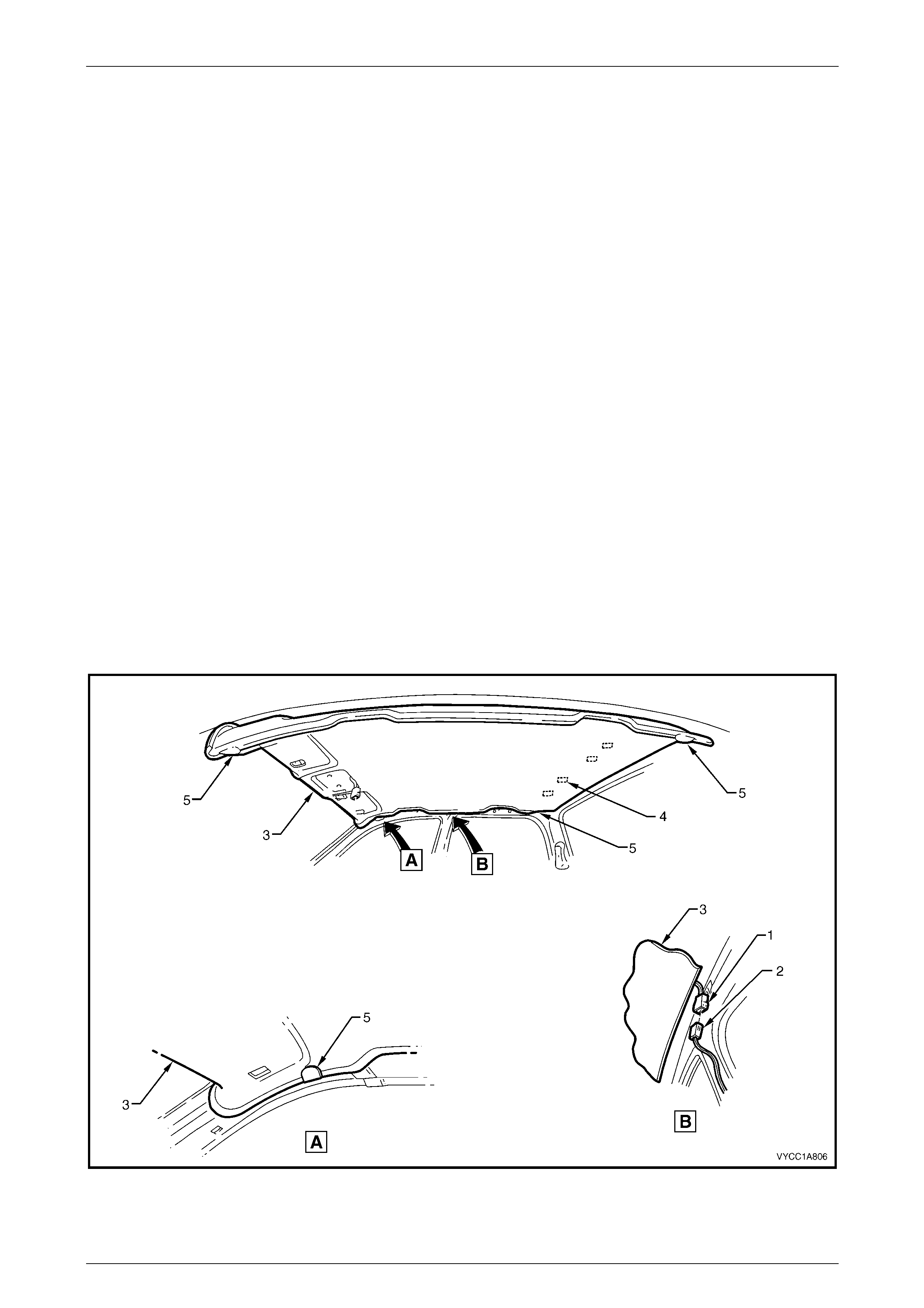
9 Disconnect the headlining assembly harness (1) from the body harness connector (2), located above and slightly
forward of the right-hand centre pillar, refer to Figure 1A8 – 9.
NOTE
It may be necessary to flex the headlining
assembly (3) down slightly to gain access to
the harness connector.
Figure 1A8 – 9
10 Carefully pull down on the rear section of the headlining to release the Velcro fasteners (4), four places.

Headlining and Int eri or Tri m Page 1A8–10
Page 1A8–10
11 With the aid of an assistant, flex the headlining assembly to disengage the corners and centre from the D-tabs (5),
six places on the sides of the roof panel.
12 Carefully remove the headlining from the vehicle.
Reinstall
1 Temporaraly support the headlining assembly on the D-tabs, (5), six places, before the trim components are
reinstalled.
2 Position the headlining and ensure the four Velcro fasteners are secured correctly.
3 Reconnect the headlining assembly wiring harness, located above and slightly forward of the right-hand centre
pillar, refer Figure 1A8 – 9.
4 Reinstallation of the remaining trim components is the reverse of the removal process.
Headlining and Int eri or Tri m Page 1A8–11
Page 1A8–11
2.7 Carpet Assembly
If required, first remove the following components:
1 Remove the right and left-hand centre pillar lowe r trims, refer to Section 1A8 Headlining and Interior Trim in the
MY 2004 VY and V2 Series Service Information.
2 Raise the rear seat cushion, refer to Section 1A7, 4.2 Rear Seat Cushion Assembly.
4 Remove the right and left-hand side sill trims, refer to Section 1A8 Headlining and Interior Trim in the MY 2004 VY
and V2 Series Service Information.
5 Remove the right and left-hand hinge pillar trim assemblies, refer to Section 1A8 Headlining and Interior Trim in
the MY 2004 VY and V2 Series Service Information.
6 Remove both front seats, refer to Section 1A7 Seat Assemblies.
7 Remove the driver's footrest, refer to Section 1A8 Headlining and Interior Trim in the MY 2004 VY and V2 Series
Service Information.
8 Remove the park brake lever cover by grasping the cover firmly by hand and sliding the cover over the park brake
lever, refer to Section 5A Service and Park Braking Systems in the MY 2003 VY and V2 Series Service
Information.
9 Remove the instrument panel compartment, refer to Section 1A3 Instrument Panel and Console in the MY 2004
VY and V2 Series Service Information.
10 Remove the instrument panel lower trim panel, refer to Section 1A3 Instrument Panel and Console in the MY 2004
VY and V2 Series Service Information.
11 Remove the right and left-hand instrument panel lower trim plate assembly, refer to Section 1A3 Instrument Panel
and Console in the MY 2003 VY and V2 Series Service Information.
12 Remove instrument panel lower extension side trim panel, refer to Section 1A3 Instrument Panel and Console in
the MY 2004 VY and V2 Series Service Information.
13 Remove floor console assembly, refer to Section 1A3 Instrument Panel and Console in the MY 2004 VY and V2
Series Service Information.
14 As required remove the following transmission selector components:
a For vehicles fitted with an automatic transmission, remove the selector control lever assembly, refer
Section 7C4, Automatic Transmission On Vehicle Servicing in the MY 2004 VY and V2 Series Service
Information.
b For vehicles fitted with manual transmission, remove the gearshift lever, refer to Section 7B1, Manual
Transmission – V6 Engine or Section 7B2, Manual Transmission - GEN III V8 Engine in the MY 2004 VY and
V2 Series Service Information.
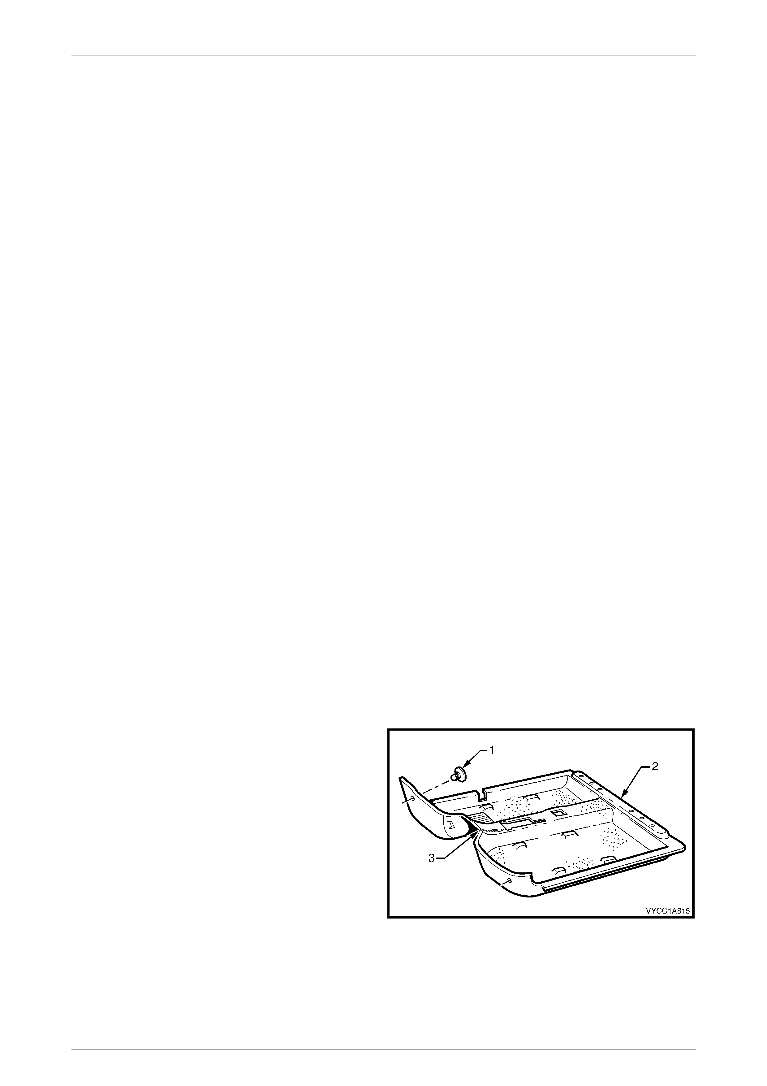
Remove
1 Remove the retaining clip (1), two places, from the
front floor carpet assembly (2) by rotating the clips
counter- clockwise and lifting clear of the attaching
studs.
NOTE
To assist in the removal and installation of the
front floor carpet assembly, it has been
perforated (3) from the front edge through the
centre of the evaporator drain cut out to the
forward edge of the lower radio bracket cut out,
refer to Figure 1A8 – 12.
Figure 1A8 – 10
Headlining and Int eri or Tri m Page 1A8–12
Page 1A8–12
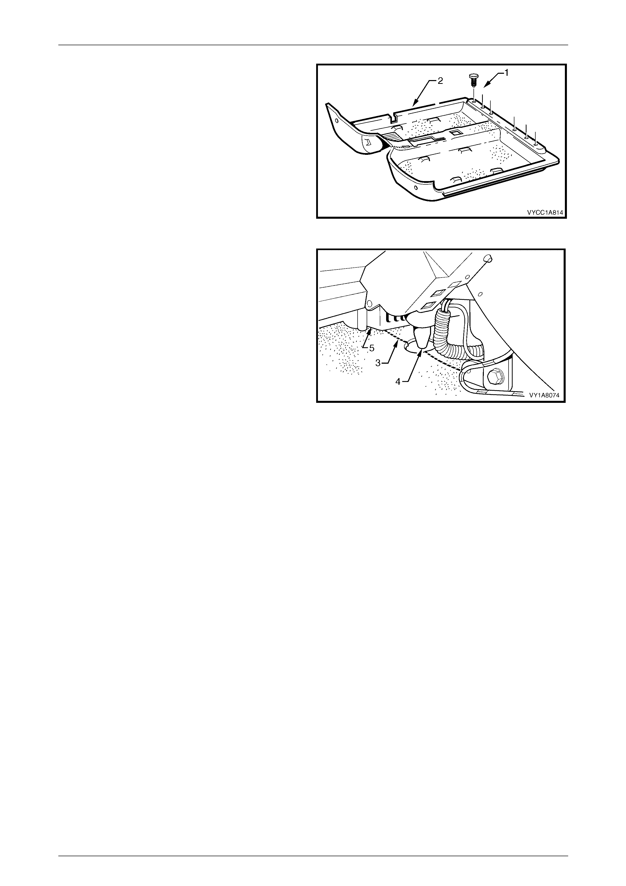
2 Remove the retaining clip (1), six places, attaching the
rear section of the floor carpet assembly (2) to the
jack boxes.
Figure 1A8 – 11
3 From with in the left-hand foot-well, grasp the edge of
the hole in the front floor carpet assembly around the
evaporator drain hose (4) and tear open the
perforated line (3) by pulling the carpet away from the
transmission tunnel.
4 Slide the remaining flap of carpet out from under the
heating, ventilation and air conditioning (HVAC) unit
(5) and into the right-hand foot-well.
5 Carefully, manoeuvre the floor carpet and insulator
assembly from the vehicle.
Figure 1A8 – 12
Reinstall
The reinstallation procedure for the front floor carpet assembly is the reverse of the removal procedure, noting the
following:
1 If a new carpet is being fitted, cut along the perforated line in the floor carpet that runs from the forward edge of
the carpet, through the evaporator drain cut-out, to the forward edge of the lower radio bracket cut-out, prior to
installation, refer Figure 1A8 – 12.
2 Ensure all the cut-outs in the carpet are correctly aligned and install the two retaining clips and the front seat belt
lower attaching bolts to secure the carpet, prior to installing the seats and console.
3 Ensure the carpet fits neatly into all corners and over the transmission tunnel and all fasteners are installed.
Headlining and Int eri or Tri m Page 1A8–13
Page 1A8–13
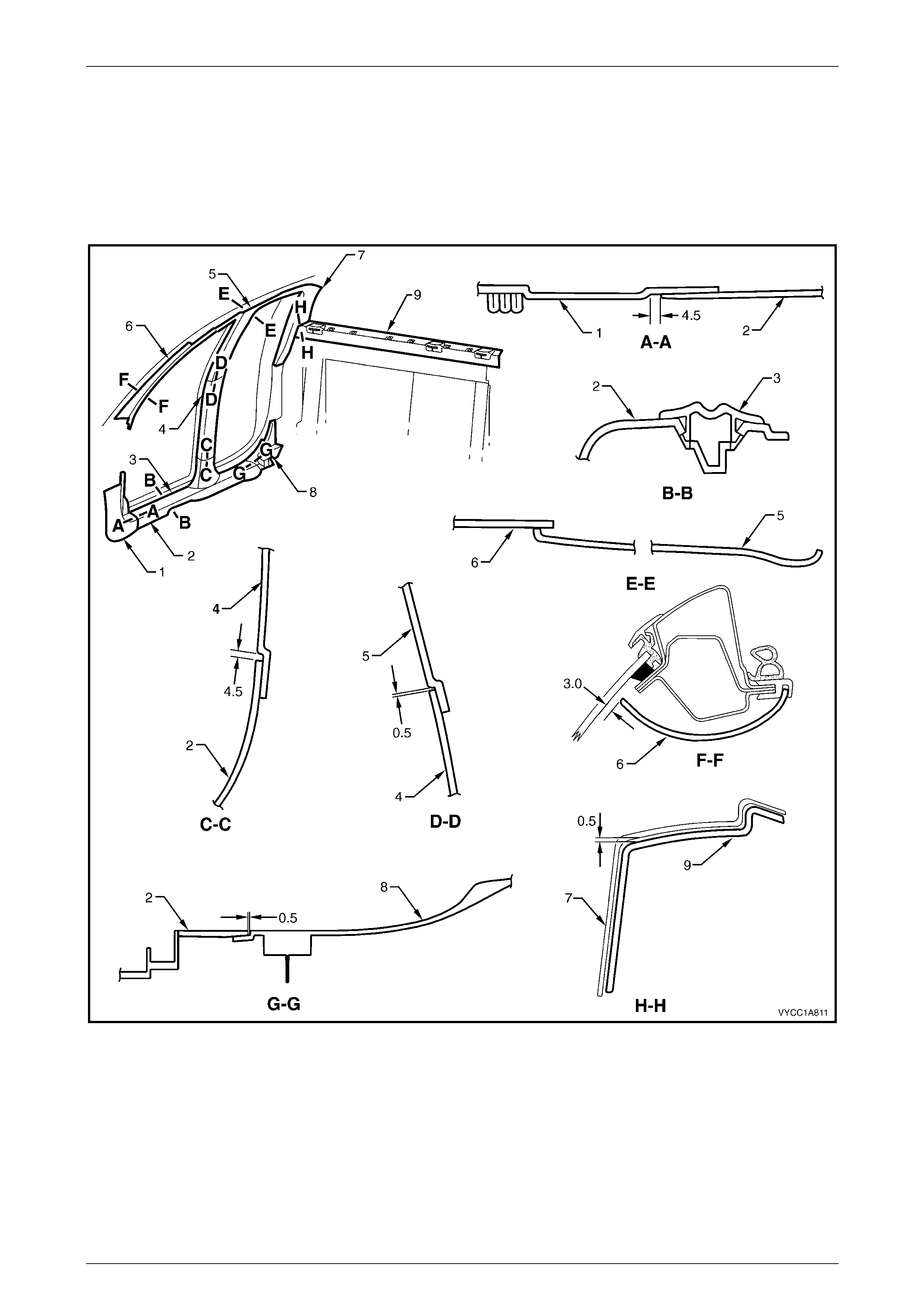
3 Trim Clearances
NOTE
All interior trim clearance measurements are in
millimetres.
Figure 1A8 – 13
1 Hinge Pillar Trim
2 Side Sill Trim
3 Sill Plate
4 Centre Pillar Lower Trim
5 Centre Pillar Upper Trim
6 Windshield Si de Garni sh
7 Body Lock Pillar Trim
8 Rocker P anel Cover Extension
9 Upper Cross-beam Cover

Headlining and Int eri or Tri m Page 1A8–14
Page 1A8–14
4 Torque Specifications
Rocker Panel Extension Screw..................................................... 1.0 – 3.0 Nm
Jack Box Screw....................................................................................25.0 Nm
Assist Handle Screw .....................................................................1.0 – 3.0 Nm
Body Lock Pillar Trim Screw .........................................................1.0 – 3.0 Nm