
Exterior Ornamentation Page 1A9–1
Page 1A9–1
Section 1A9
Exterior Ornamentation
ATTENTION
Before performing any service operation or other procedure described in this Section, refer to Section 00
Warnings, Cautions and Notes for correct workshop practices w ith regard to safety and/or property damage.
1 General Information............................................................................................................................... 3
2 Service Operations................................................................................................................................ 4
2.1 Pictorial Index .........................................................................................................................................................4
Reference Chart .....................................................................................................................................................6
2.2 Body Lock Pillar Door Moulding...........................................................................................................................7
Remove ...................................................................................................................................................................7
Reinstall..................................................................................................................................................................7
2.3 Door Opening Moulding ........................................................................................................................................8
Remove ...................................................................................................................................................................8
Reinstall..................................................................................................................................................................8
2.4 Body Lock Pillar Trim ............................................................................................................................................9
Remove ...................................................................................................................................................................9
Reinstall..................................................................................................................................................................9
2.5 Body Lock Pillar Finisher ....................................................................................................................................10
Remove .................................................................................................................................................................10
Reinstall................................................................................................................................................................10
2.6 Rear Header Trim .................................................................................................................................................11
Remove .................................................................................................................................................................11
Reinstall................................................................................................................................................................11
2.7 Rear Header Trim Retainer..................................................................................................................................13
Remove .................................................................................................................................................................13
Reinstall................................................................................................................................................................13
2.8 Roof Panel Joint Moulding..................................................................................................................................14
Remove .................................................................................................................................................................14
Reinstall................................................................................................................................................................14
2.9 Rear Window Lower Finisher..............................................................................................................................15
Remove .................................................................................................................................................................15
Reinstall................................................................................................................................................................15
2.10 Rear Outer Trim Panel and NVH Foam...............................................................................................................16
Remove .................................................................................................................................................................16
Reinstall................................................................................................................................................................17
2.11 Rocker Panel Moulding Assembly......................................................................................................................18
Remove .................................................................................................................................................................18
Reinstall................................................................................................................................................................18
2.12 Rear Body Front Rocker Moulding.....................................................................................................................19
Remove .................................................................................................................................................................19
Reinstall................................................................................................................................................................19
2.13 Rear Body Rear Rocker Moulding ......................................................................................................................20
Remove .................................................................................................................................................................20
Reinstall................................................................................................................................................................20
2.14 Rear Body Rail Cover...........................................................................................................................................21
Remove .................................................................................................................................................................21
Reinstall................................................................................................................................................................21

Exterior Ornamentation Page 1A9–2
Page 1A9–2
2.15 Rear Body Front Rail Cover.................................................................................................................................22
Remove .................................................................................................................................................................22
Reinstall................................................................................................................................................................22
2.16 Emblems and Name Plates .................................................................................................................................23
Rear Door Nameplate – SS..................................................................................................................................23
Remove............................................................................................................................................................23
Reinstall............................................................................................................................................................23
Endgate Nameplate – Crewman..........................................................................................................................24
Remove............................................................................................................................................................24
Reinstall............................................................................................................................................................24
Endgate Nameplate – S and SS ..........................................................................................................................24
Remove............................................................................................................................................................24
Reinstall............................................................................................................................................................24
3 Torque Wrench Specifications........................................................................................................... 26
Exterior Ornamentation Page 1A9–3
Page 1A9–3
1 General Information
With the following exceptions, MY 2004 VY Regular Cab and Crew Cab Exterior Ornamentation information carries over
from MY 2004 VY Series vehicles and MY 2003 VY Regular Cab vehicles.
Crew Cab:
• Rear header trim
• Roof panel joint moulding
• Door opening moulding
• Body lock pillar trim
• Rear body rail covers
• Rocker panel mouldings
• Body lock pillar finisher
• Rear window lower finisher
• Rear outer trim panel and NVH foam
• Rear door name plate
• Endgate name plates
For exterior ornamentation information not contained within this Section, refer to Section 1A9 Exterior Ornamentation in
the MY 2004 VY and V2 Series Service Information and Section 1A9 Exterior Ornamentation in the MY 2003 VY Regular
Cab Service Information.
To aid in identification and service procedure location, refer to the pictorial index diagram on the following pages.
Many of the components are affixed to the
vehicle with double-sided adhesive tape. It is
imperative that the correct materials, as
specified in this Section are used when
reassembling these parts. Use of materials
other than those specified may lead to
premature failure.
NOTE
Some exterior ornamentation fastening screws
are encapsulated with a wax sealer. It is
recommended that the screws be replaced once
removed, however if this is impractical, apply a
small amount of sealer to the end of the thread.

Exterior Ornamentation Page 1A9–4
Page 1A9–4
2 Service Operations
2.1 Pictorial Index
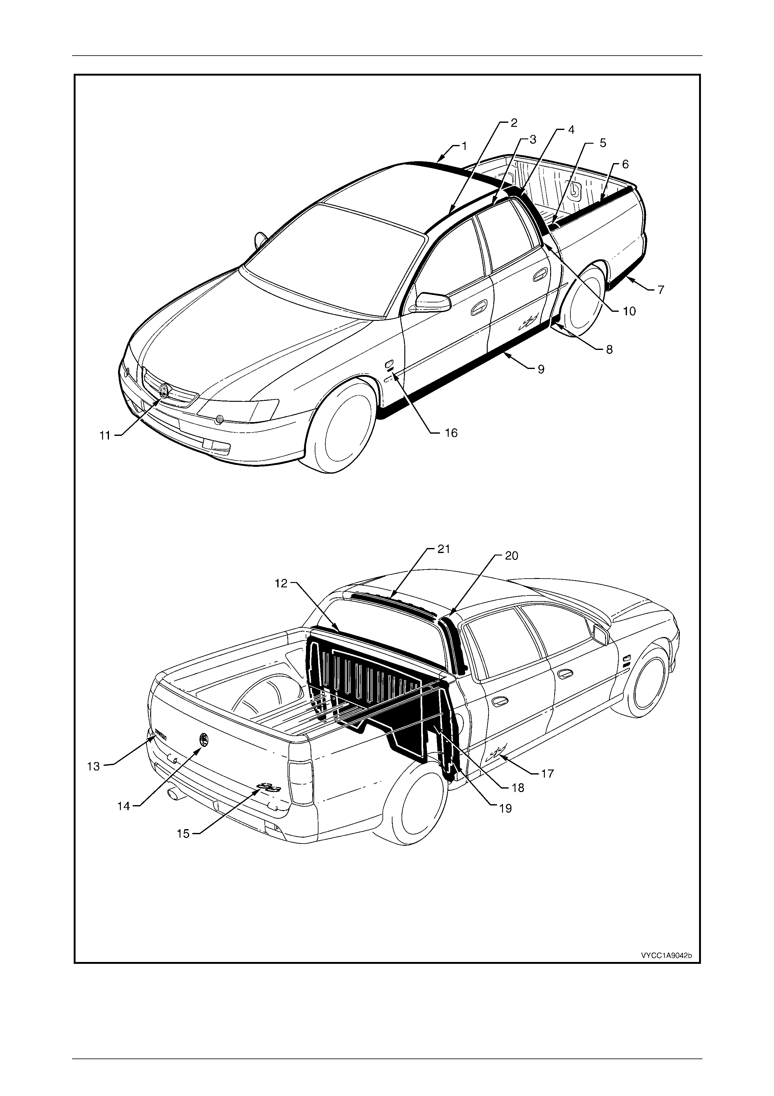
The following diagram provides a quick reference to the correct service procedures for the exterior ornamentation
components.
Simply locate the component in Figure 1A9 – 1, cross-reference it in the accompanying table below the figure and using
the reference listed, go to the appropriate service procedure.
Exterior Ornamentation Page 1A9–5
Page 1A9–5
Figure 1A9 – 1

Exterior Ornamentation Page 1A9–6
Page 1A9–6
Reference Chart
Item Description Refer to
1 Rear Header Trim 2.6 Rear Header Trim
2 Roof Panel Joint Moulding 2.8 Roof Panel Joint Moulding
3 Door Opening Moulding 2.3 Door Opening Moulding
4 Body Lock Pillar Trim 2.4 Body Lock Pillar Trim
5 Rear Body Front Rail Cover 2.15 Rear Body Front Rail Cover
6 Rear Body Rail Cove r 2.14 Rear Body Rail Cove r
7 Rear Body Rear Rocker Moulding 2.13 Rear Body Rear Rocker Moulding. Excludes SS.
8 Rear Body Front Rocker Moulding 2.12 Rear Body Front Rocker Moulding
9 Rocker Panel Moulding Assembly 2.11 Rocker Panel Moulding Assembly
10 Body Lock Pillar Door Moulding 2.2 Body Lock Pillar Door Moulding
11 Radiator Grille Emblem: Holden Section 1A9, 4.1 Radiator Grille Emblem in the MY2003 VY and V2
Series Service Information.
12 Rear Window Lower Finisher 2.9 Rear Window Lower Finisher
13 Endgate Name Plate: Crewman 2.16 Emblems and Name Plates
14 Endgate Emblem: Holden Section 1A9, 4.4 Endgate Emblem in the MY 2003 VY and V2 Series
Service Information.
15 Endgate Name Plate: S, SS 2.16 Emblems and Name Plates
16 Fender Name Plate:
V6, V8 Section 1A9, 4.2 Fender Name Plate in the MY 2003 VY and V2
Series Service Information.
17 Rear Door Name Plate: SS 2.16 Emblems and Name Plates
18 Rear Outer Trim Panel 2.10 Rear Outer Trim Panel and NVH Foam
19 NVH Foam 2.10 Rear Outer Trim Panel and NVH Foam
20 Body Lock Pillar Finisher 2.5 Body Lock Pillar Finisher
21 Rear Header Retainer 2.7 Rear Header Trim Re tainer
Exterior Ornamentation Page 1A9–7
Page 1A9–7
2.2 Body Lock Pillar Door Moulding
Remove
1 Remove the screw (1), two places, attaching the body
lock pillar door moulding (2) and remove the
moulding.
Figure 1A9 – 2
Reinstall
Reinstallation of the body lock pillar door moulding is the reverse of the removal procedure. Tighten the attaching
screws to the correct torque specification.
Body lock pillar door moulding
attaching screw torque specification......... .0.3 – 1.0 Nm
Exterior Ornamentation Page 1A9–8
Page 1A9–8
2.3 Door Opening Moulding
Remove
1 Open the front and rear doors on the relevant side of
the vehicle.
2 Beginning at each end and working towards the
middle of the door opening moulding (1), remove the
screw (2), 10 places, attaching the door opening
moulding to the vehicle.
3 Carefully remove the moulding.
Figure 1A9 – 3
Reinstall
Reinstallation of the door opening moulding is the reverse of the removal procedure, noting the following:
NOTE
The screws are encapsulated with a wax sealer.
It is recommended that the screws be replaced
once removed, however if this is impractical,
apply a small amount of sealer to the end of the
thread.
1 Tighten the attaching screws to the correct torque specification.
Door opening moulding attaching
screw torque specification.......................... 0.3 – 1.0 Nm
Exterior Ornamentation Page 1A9–9
Page 1A9–9
2.4 Body Lock Pillar Trim
Remove
1 Remove the body lock pillar door moulding, refer to 2.2 Body Lock Pillar Door Moulding.
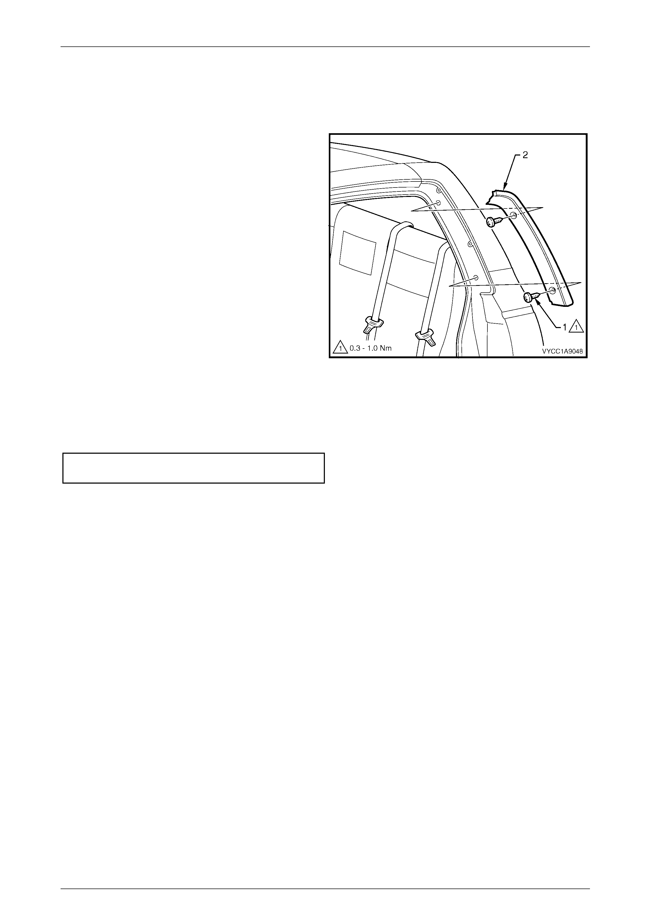
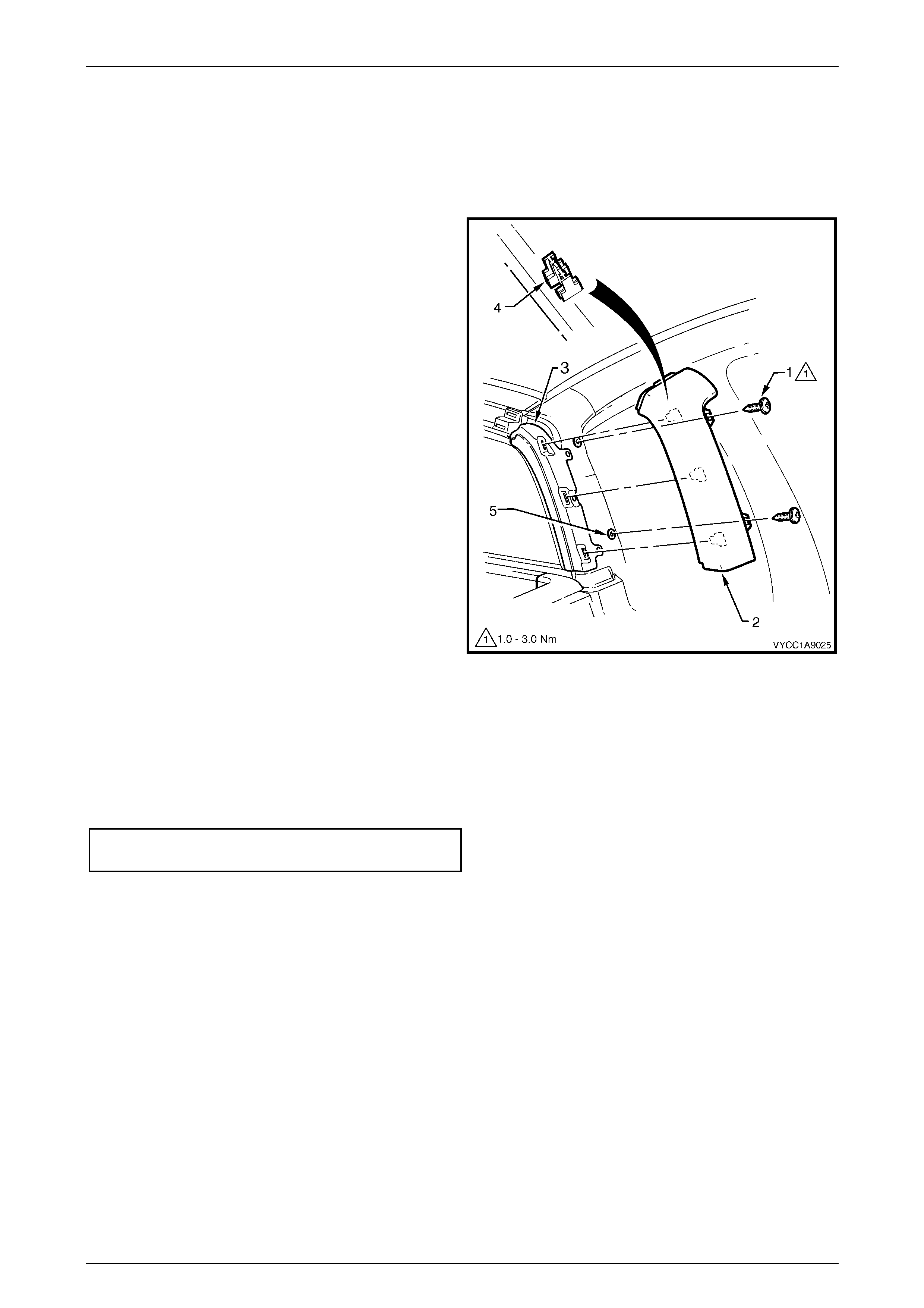
2 Remove the screw (1), two places, attaching the body
lock pillar trim (2), to the body lock pillar.
3 Remove the trim from the body lock pillar finisher (3),
disengaging the three retaining clips (4).
4 If required remove the foam seals (5), two places.
Figure 1A9 – 4
Reinstall
Reinstallation of the body lock pillar trim is the reverse of the removal procedure, noting the following:
1 If required, position the foam seals centrally over the holes for the attaching screws, refer to Figure 1A9 – 4.
2 Tighten the attaching screws to the correct torque specification.
Body lock pillar trim attaching
screw torque specification.......................... 1.0 – 3.0 Nm
Exterior Ornamentation Page 1A9–10
Page 1A9–10
2.5 Body Lock Pillar Finisher
Remove
1 Remove the body lock pillar trim, refer to 2.4 Body Lock Pillar Trim.
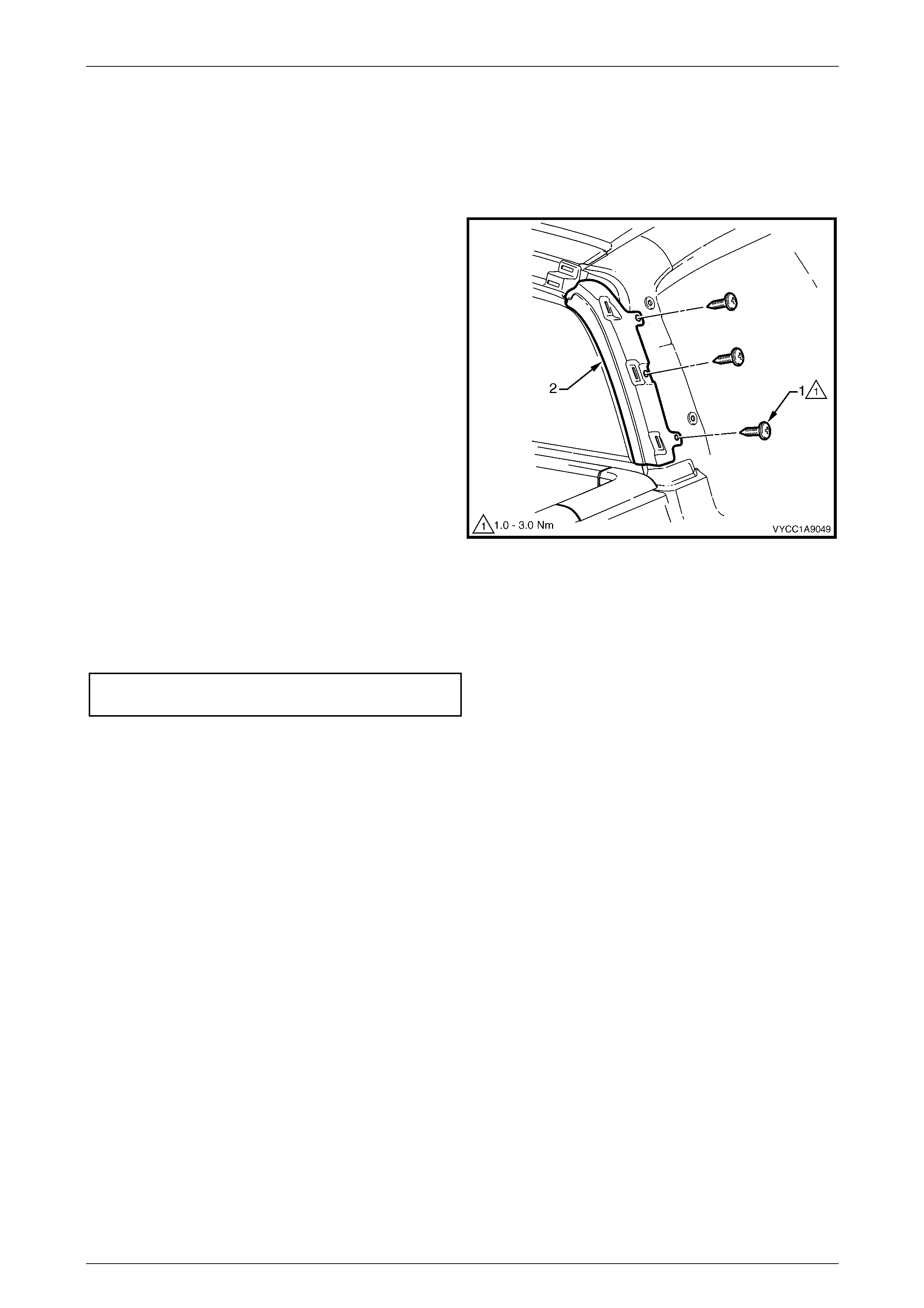
2 Remove the screw (1), three places, attaching the
body lock pillar finisher (2) to the body lock pillar and
remove.
Figure 1A9 – 5
Reinstall
Reinstallation of the body lock pillar finisher is the reverse of the removal procedure. Tighten the attaching screws to the
correct torque specification.
Body lock pillar finisher
attaching screw torque specification.......... 1.0 – 3.0 Nm
Exterior Ornamentation Page 1A9–11
Page 1A9–11
2.6 Rear Header Trim
Remove
1 Remove the body lock pillar trim, refer to 2.4 Body Lock Pillar Trim.
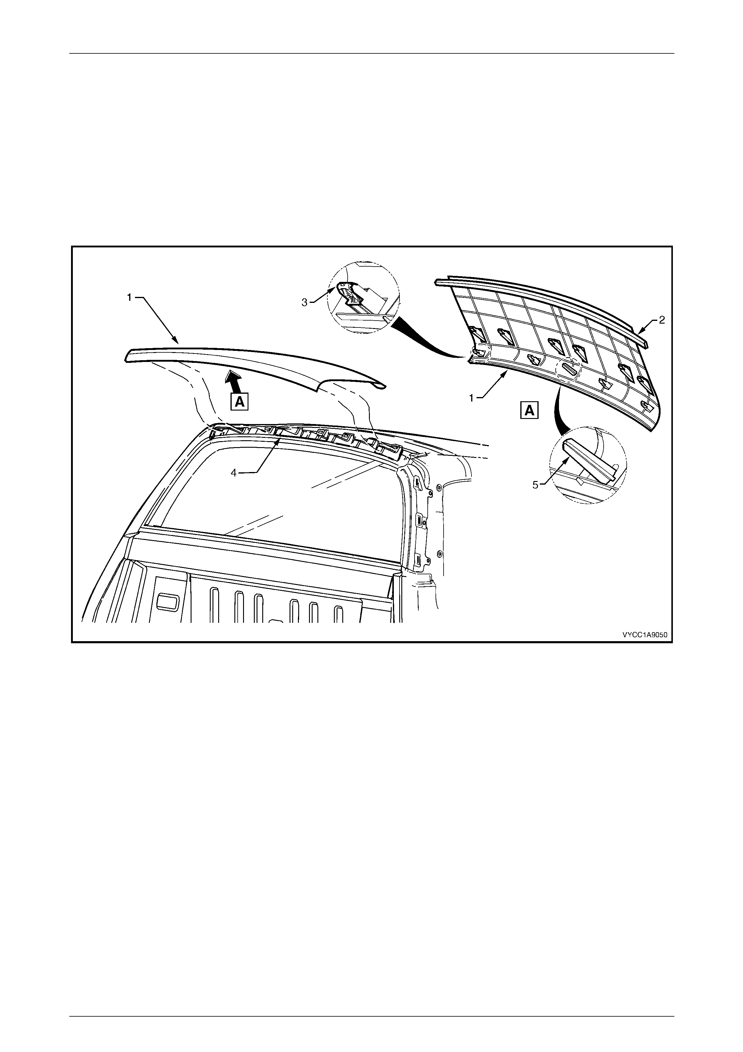
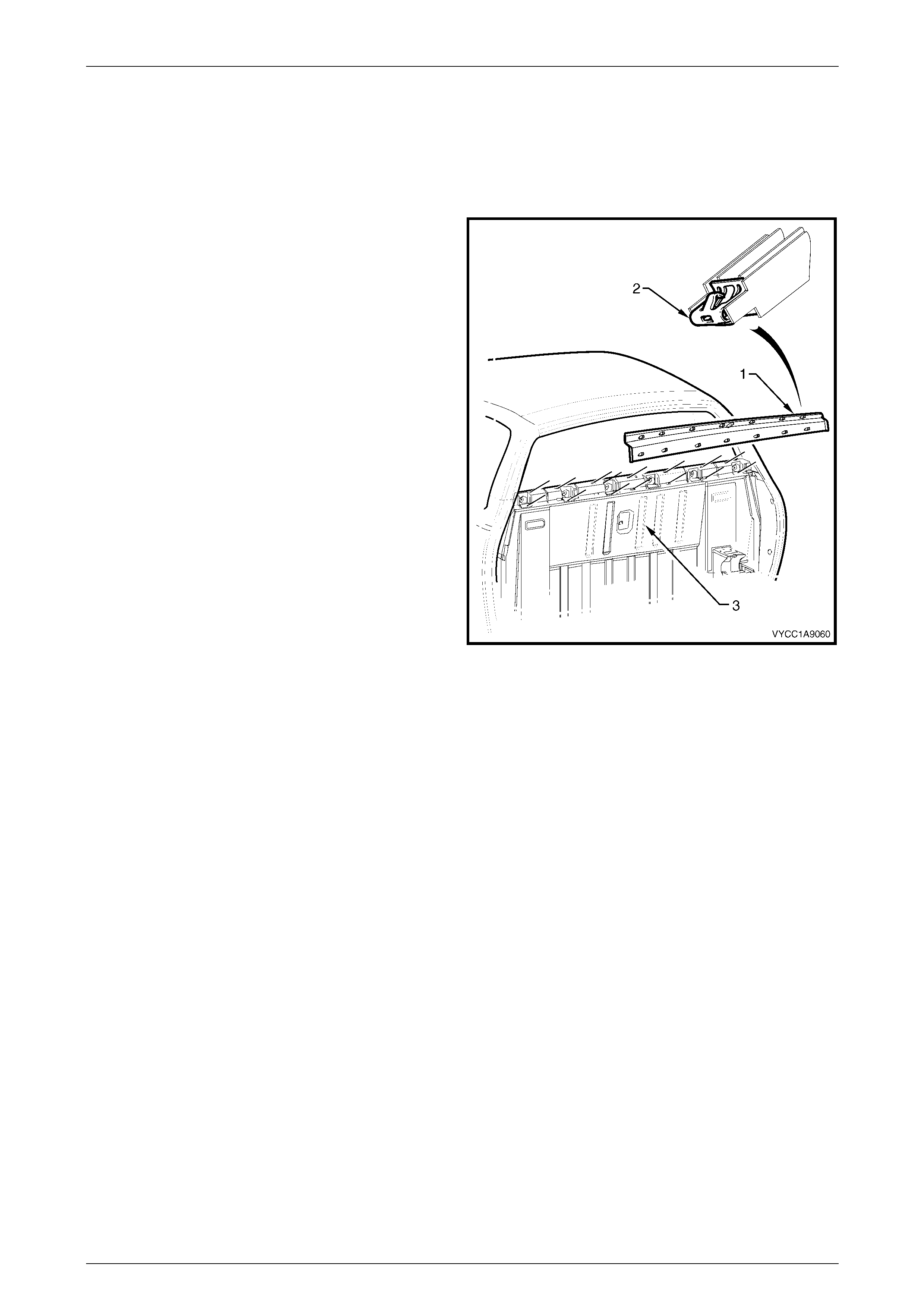
2 Starting from the front edge, prise the rear header trim (1) free from the double sided adhesive tape (2), refer to
Figure 1A9 – 6.
3 Gently pull the rear header trim assembly rearward to release the retaining clips (3), 10 places, from the rear
header trim retainer (4).
Figure 1A9 – 6
Reinstall
1 As required, thoroughly clean and dry the roof panel and trim along the surfaces to be contacted with the double
sided tape using Prepsol or equivalent.
Exterior Ornamentation Page 1A9–12
Page 1A9–12
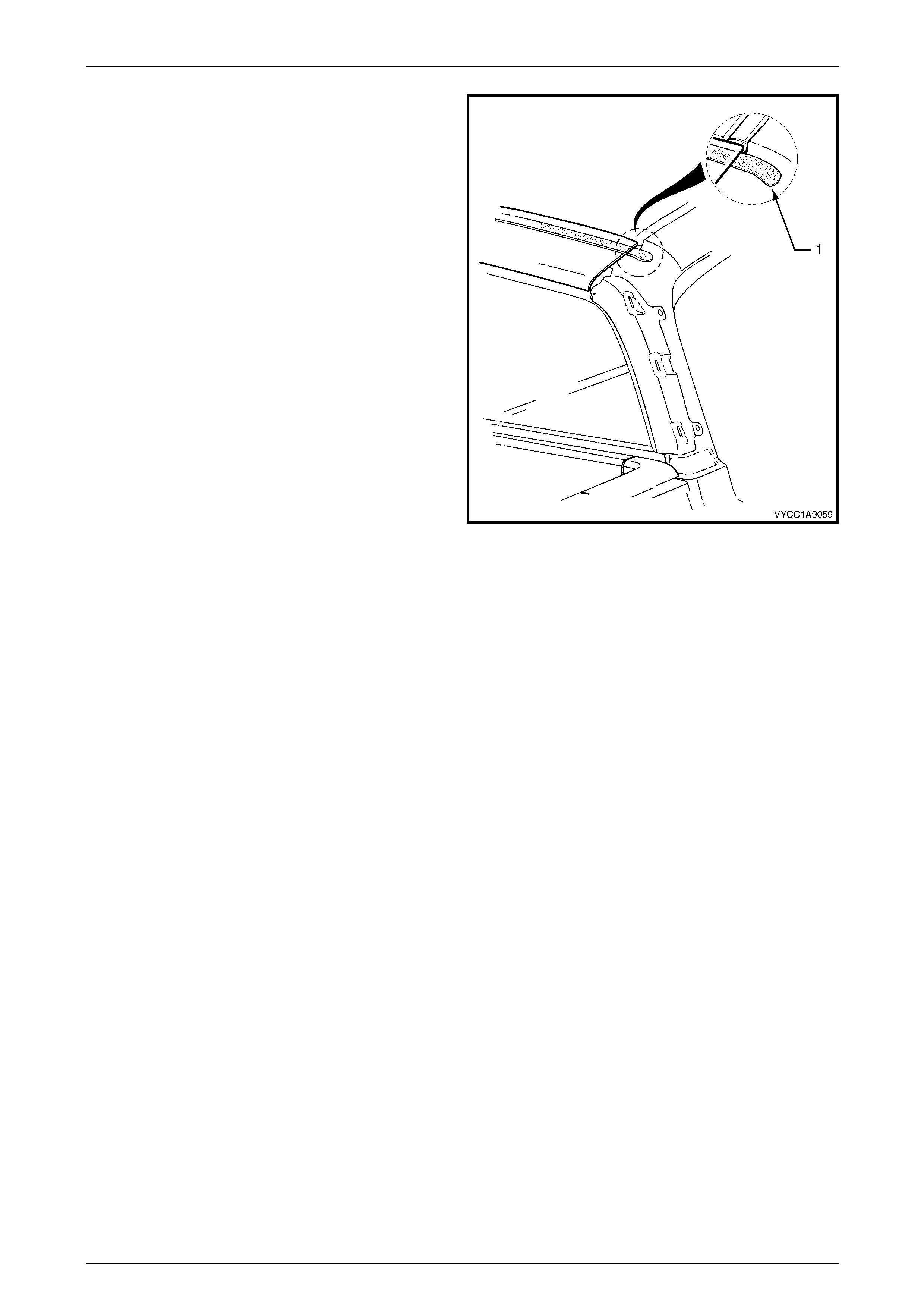
2 If reinstalling the existing header trim, apply a length
of double sided tape, such as 3M 4428 or equivalent
along the mating surface of the trim assembly, leaving
at least a 30 mm overhang of tape at either end (1).
NOTE
Do not remove the backing paper from the
double sided tape at this stage.
3 Position the header trim so that the locating pins (5)
are aligned with the slots in the rear header trim
retainer moulding. Starting at a corner of the rear
header trim, hold the front edge up slightly and gently
tap the header trim evenly until all retaining clips
engage into position, refer to Figure 1A9 – 6.
4 Check for correct alignment of the header trim.
5 Peel the backing paper from the underside of one end
of the double sided tape (1).
6 Position and press the double sided tape down onto
the roof panel. Peel back and remove the remaining
length of backing paper and allow the rear header trim
to contact and adhere to the roof panelling.
7 Firmly press down along the front edge of the header
trim to ensure that the double sided tape is completely
adhered to the roof panel. Figure 1A9 – 7
8 Reinstall the body lock pillar trim, refer to 2.4 Body Lock Pillar Trim.
Exterior Ornamentation Page 1A9–13
Page 1A9–13
2.7 Rear Header Trim Retainer
Remove
1 Remove the rear header trim, refer to 2.6 Rear Header Trim.
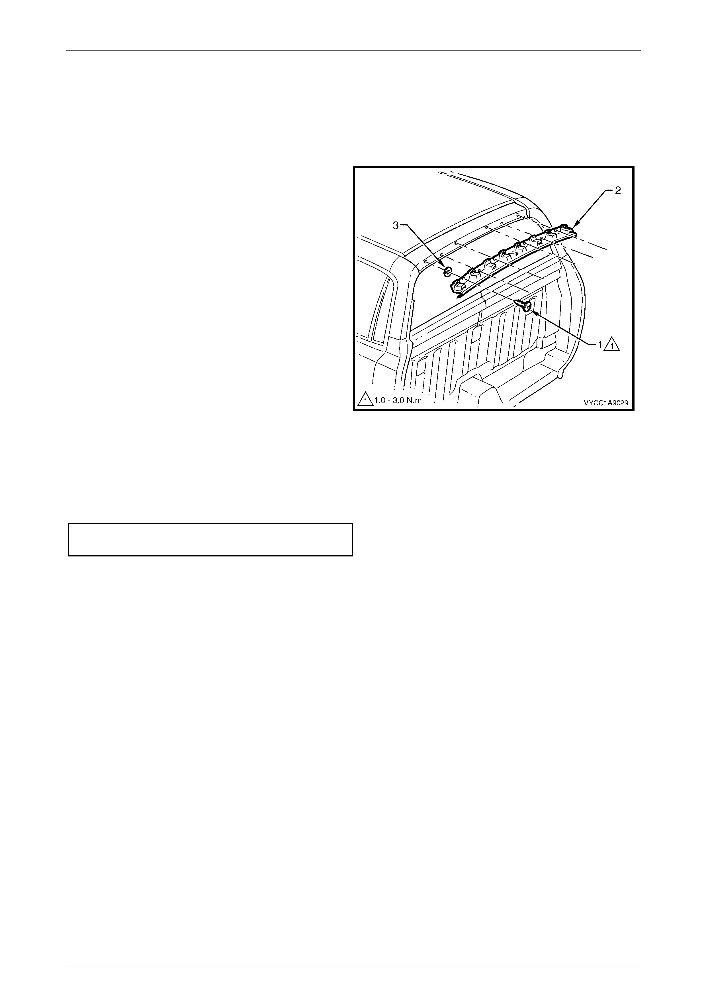
2 Remove the screw (1), six places, attaching the rear
header trim retainer (2) to the roof panel.
3 If required, remove the foam seal (3), six places, from
the roof panel.
Figure 1A9 – 8
Reinstall
1 Position the foam seals, centrally over the screw holes in the roof panel, refer to Figure 1A9 – 8.
2 Align the retainer with the screw holes, install the screws and tighten to the correct torque specification.
Rear header trim retainer attaching
screw torque specification.......................... 1.0 – 3.0 Nm
3 Refit the rear header trim, refer to 2.6 Rear Header Trim.
Exterior Ornamentation Page 1A9–14
Page 1A9–14
2.8 Roof Panel Joint Moulding
Remove
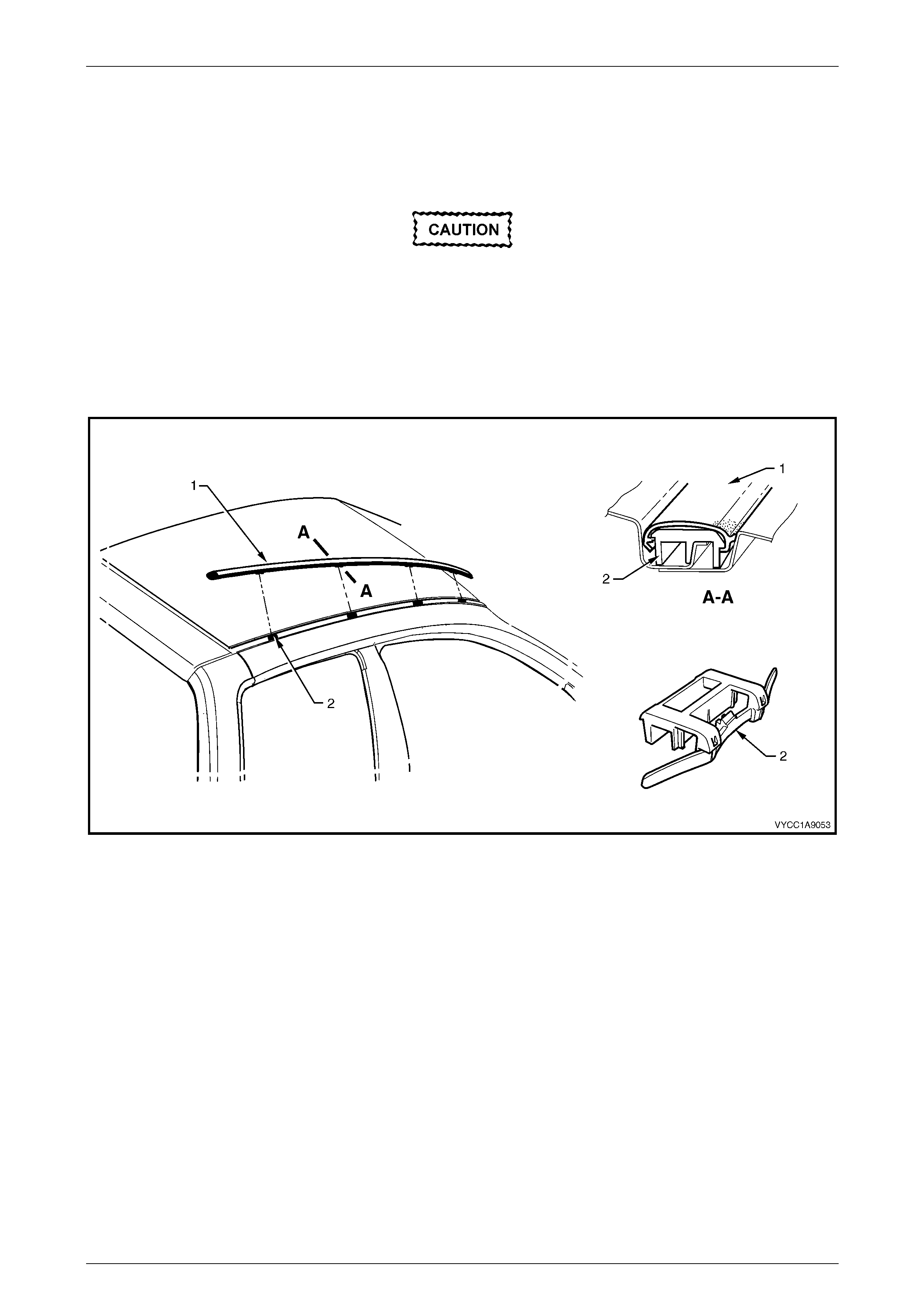
Take care as the retaining clips can easily
break. Protect the paintwork with a shop
cloth.
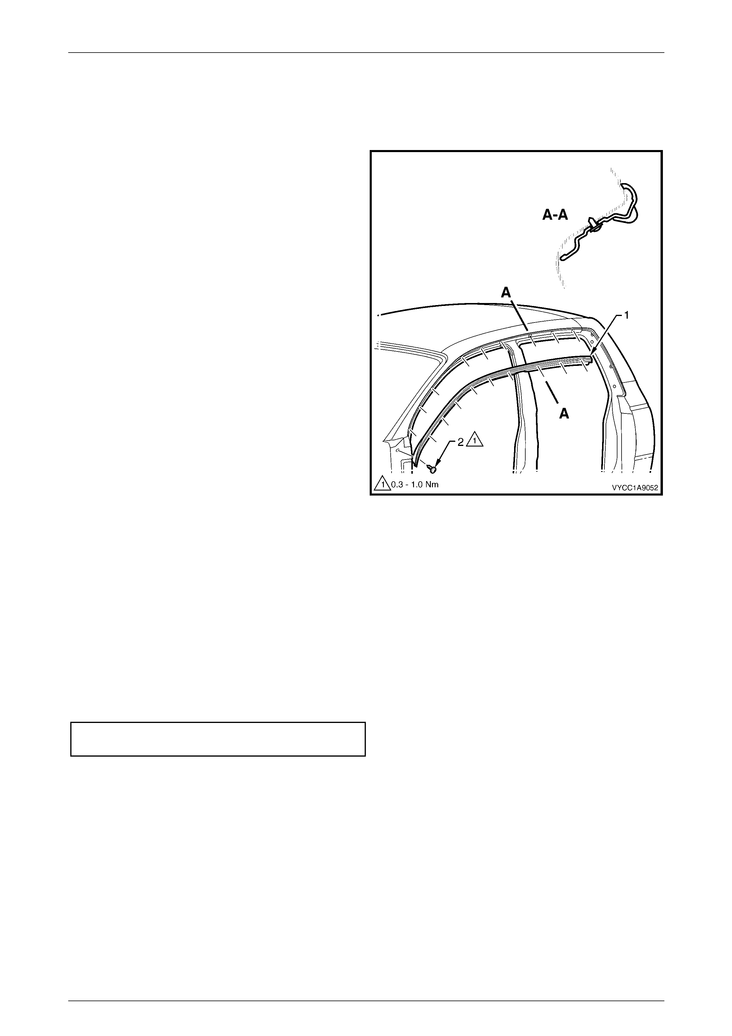
1 Beginning at the front of the roof panel, use a screwdriver to carefully prise the roof panel joint moulding (1) from
the roof channel, disengaging the retaining clips (2) at four places.
2 Disengage the rear locating lug on the roof panel joint moulding from the rear header trim by lifting the moulding at
the front.
Figure 1A9 – 9
Reinstall
1 Ensure the roof joint channel is clean and clear of sealant which may obstruct the clips.
2 As required, seat the four clips onto the roof joint moulding, spaced as indicated.
3 Position the roof joint moulding locating lug in position in the rear header trim.
4 Seat the roof joint moulding over the roof channel and beginning at the rear, clip it in place ensuring the moulding
is installed under the windshield moulding cover.
Exterior Ornamentation Page 1A9–15
Page 1A9–15
2.9 Rear Window Low er Finisher
Remove
1 If required, remove the rear body assembly, refer to Section 1B Sheetmetal and Rear Subframe.
2 Beginning at either edge, use a flat blade screwdriver
to gently prise the rear window lower finisher (1) up to
disengage the retainer clips (2) from the slots in the
rear outer trim panel (3).
3 Remove the finisher.
Figure 1A9 – 10
Reinstall
1 Align the rear window lower finisher with the slots in the rear outer trim panel and apply hand pressure evenly to
the outer face of the finisher to engage each of the retainer clips.
2 Reinstall the rear body assembly if removed, refer to Section 1B Sheetmetal and Rear Subframe.
Exterior Ornamentation Page 1A9–16
Page 1A9–16
2.10 Rear Outer Trim Panel and NVH Foam
Remove
1 Remove the rear body assembly, refer to Section 1B Sheetmetal and Rear Subframe.
2 Remove the rear window lower finisher, refer to 2.9 Rear Window Lower Finisher.
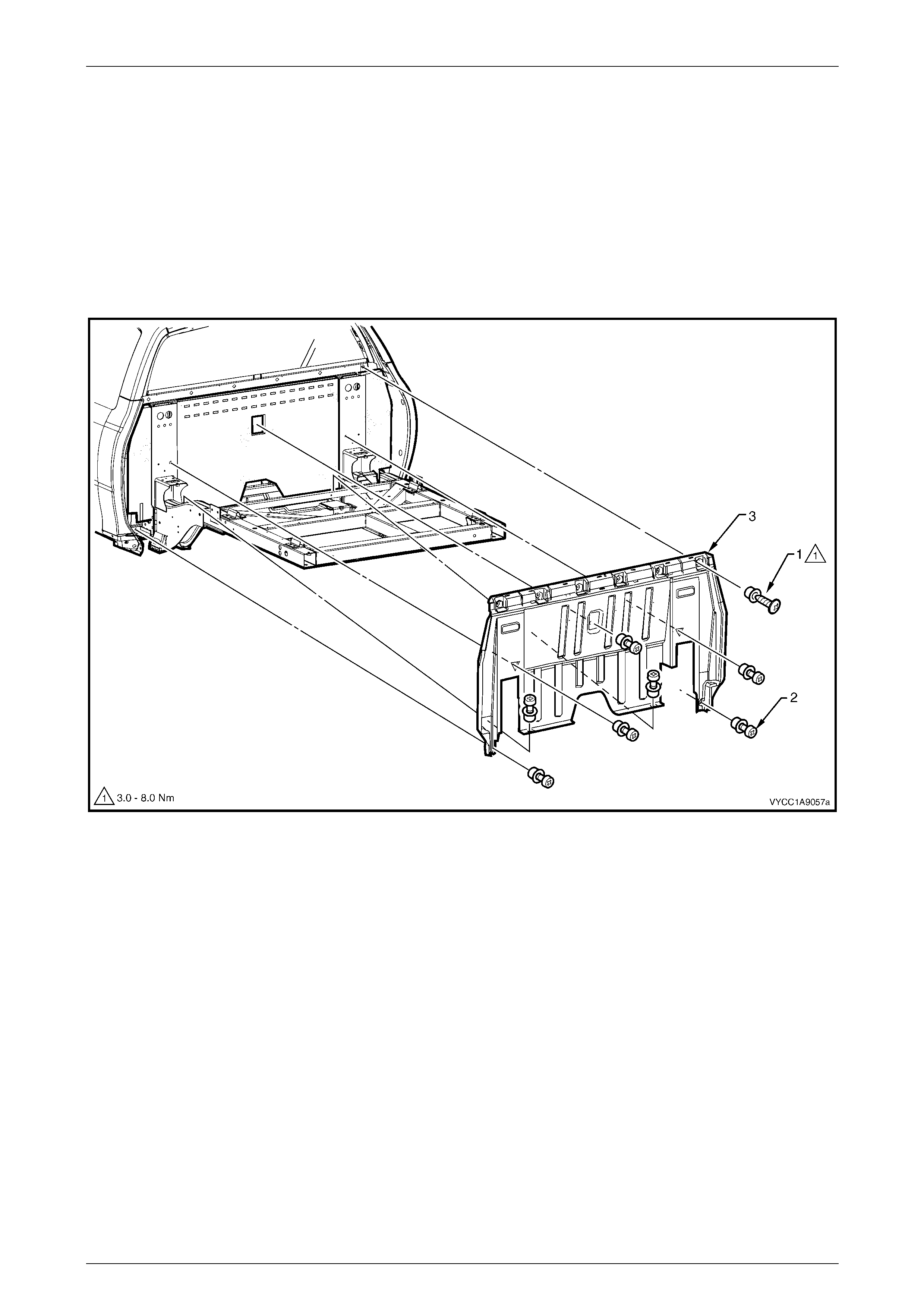
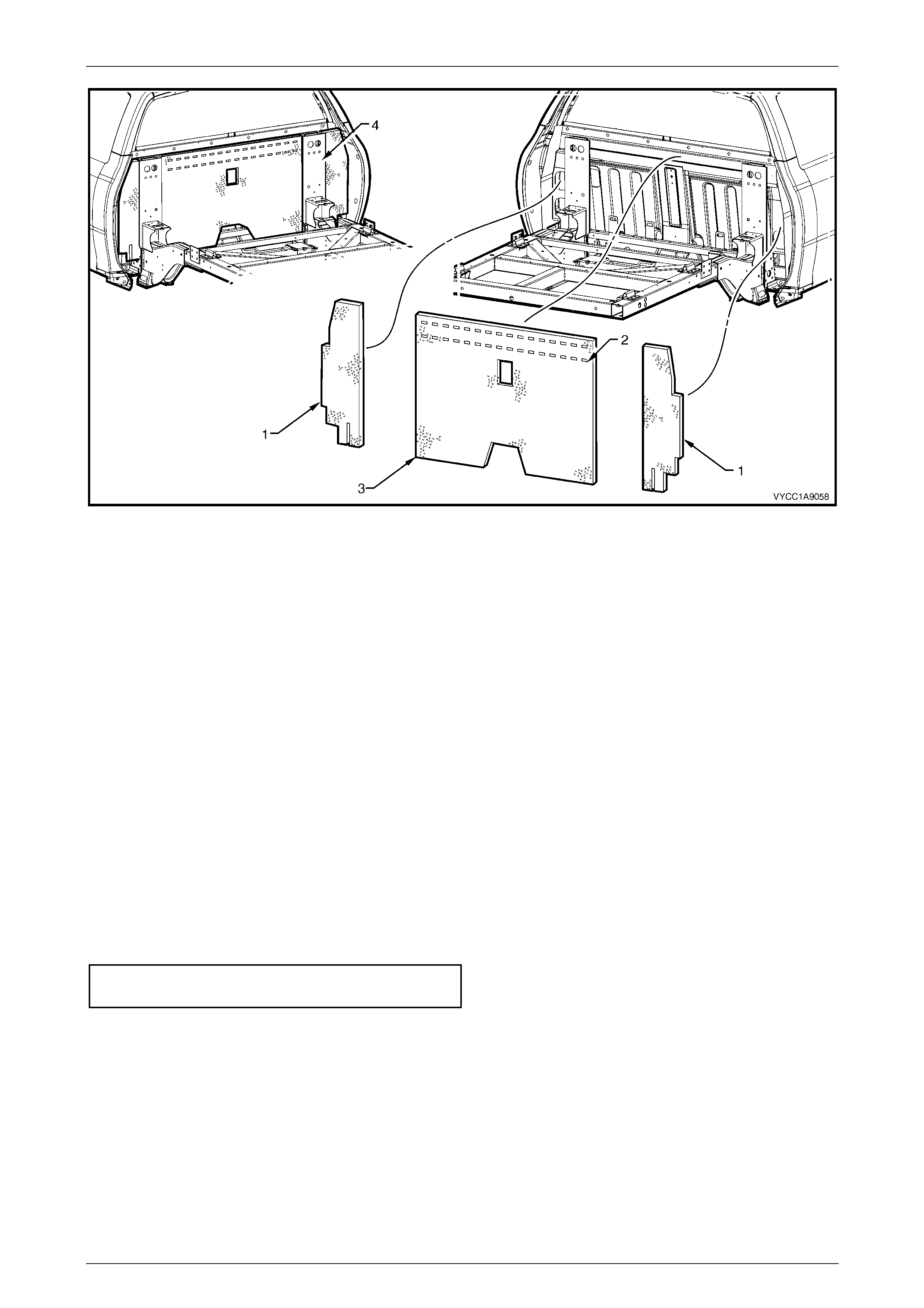
3 Remove the rear outer trim panel attaching screws and cups (1), six places, refer to
Figure 1A9 – 11.
4 Remove the rear outer trim panel retainers (2), seven places, and remove the rear outer trim panel (3).
Figure 1A9 – 11
5 As required, remove the NVH Foam, referring to Figure 1A9 – 12 for the following:
a Note the routing of the wiring harness at the lower right-hand side of the rear outer trim panel and NVH foam.
b Carefully pull the two outer sections of foam (1) from inside the panelling cavity and remove.
c Use a flat-blade scraper to dislodge the hot-melt glue (2) attaching the centre section of foam (4) onto the
body panelling and remove the foam, refer to Figure 1A9 – 12.
Exterior Ornamentation Page 1A9–17
Page 1A9–17
Figure 1A9 – 12
Reinstall
NOTE
The outer sections of the NVH foam are identical
and can be installed at either side of the vehicle.
When installed correctly, the glossy backing
attached to the foam will be visible on one side of
the vehicle only.
1 Remove any hot-melt glue remaining on the body panelling using a scraper and Prepsol or equivalent to
thoroughly clean and dry the surface.
2 Position the two outer side foam pieces into the panel cavity, and tuck each inner edge evenly behind the rear
sub-frame (4), refer to Figure 1A9 – 12.
3 Route the wiring harness as noted during the removal procedure.
4 Apply two solid rows of hot-melt glue along the top inner face of the centre section of foam as indicated.
5 Fit the foam into position and firmly press the foam onto the panel to ensure correct adhesion is achieved.
6 Fit the rear outer trim panel and install the seven retainers, refer to Figure 1A9 – 11.
7 Install the rear outer trim panel to body attaching screws, six places and tighten to the correct torque specification.
Rear outer trim panel attaching screw
torque specification.................................... 3.0 – 8.0 Nm
8 Install the rear window lower finisher, refer to 2.9 Rear Window Lower Finisher.
9 Install the rear body assembly, refer to Section 1B Sheetmetal and Rear Subframe.
Exterior Ornamentation Page 1A9–18
Page 1A9–18
2.11 Rocker Panel Moulding Assembly
Remove
Refer to Figure 1A9 – 13 for the following:
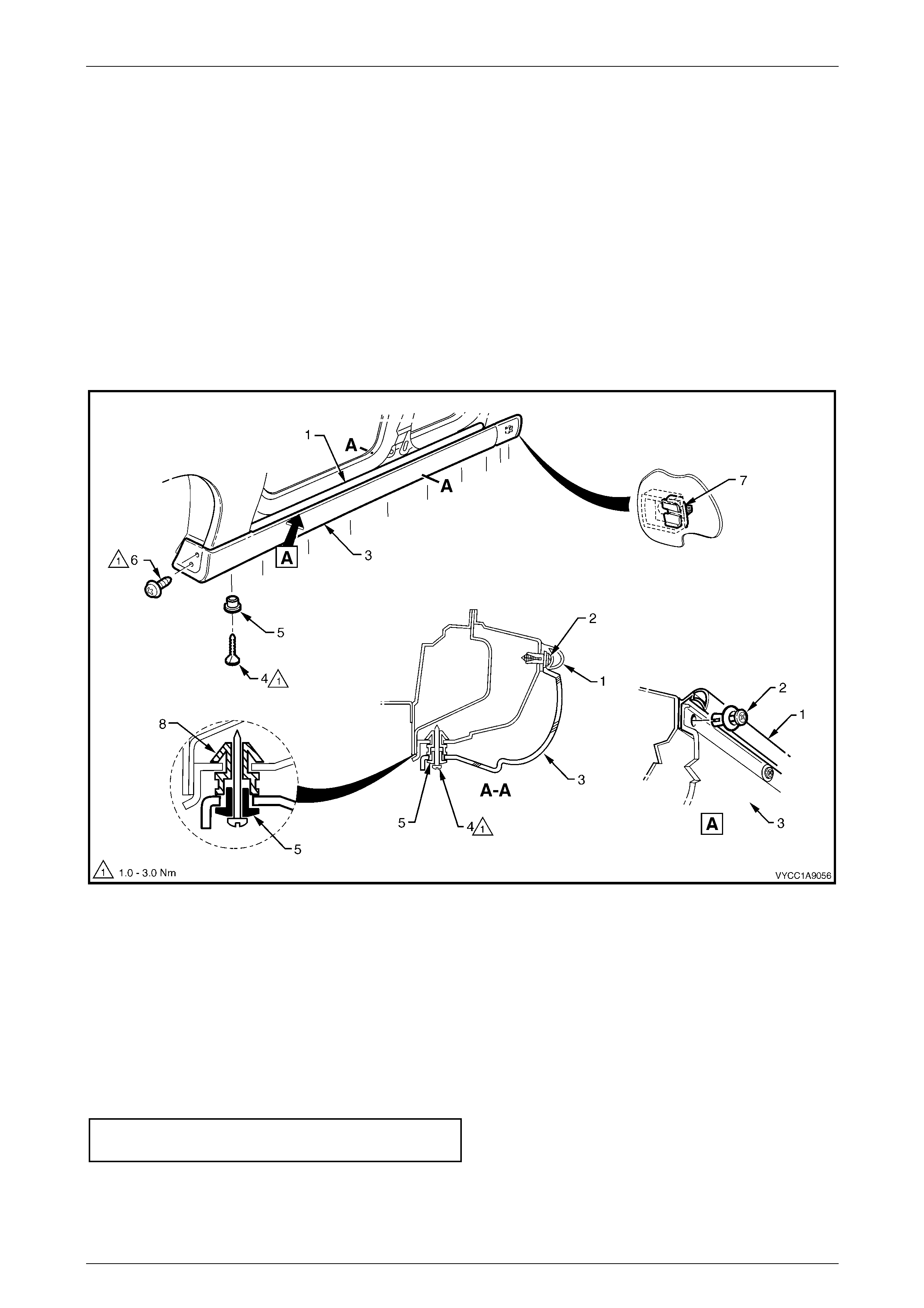
1 Lift up the rocker panel weatherstrip (1) to gain access and remove the retainer (2), nine places, attaching both the
rocker moulding (3) and weather strip to the front body rocker panel.
2 Remove the screw and cup (4 and 5), 10 places, from the underside of the rocker moulding.
3 Remove the screw (6), two places, attaching the rocker moulding to the fender and liner.
4 From the rear outside edge of the rocker moulding, push forward to slide the moulding clear of the retaining clip (7)
and remove the weather strip and the moulding.
5 If removed, remove the retaining clip from the body panelling and place to one side.
Figure 1A9 – 13
Reinstall
Reinstallation of the front body rocker moulding is the reverse of the removal procedure, noting the following:
1 Check that all ten retainers (8) are installed correctly and replace where necessary, refer to
Figure 1A9 – 13.
2 Install the retaining clip into the holder on the back of the rocker moulding and, with the weatherstrip in place,
press the moulding against the rocker panelling to clip it into position.
3 Tighten the attaching screws to the correct specified torque.
Rocker panel moulding attaching
screw torque specification.......................... 1.0 – 3.0 Nm
Exterior Ornamentation Page 1A9–19
Page 1A9–19
2.12 Rear Body Front Rocker Moulding
Remove
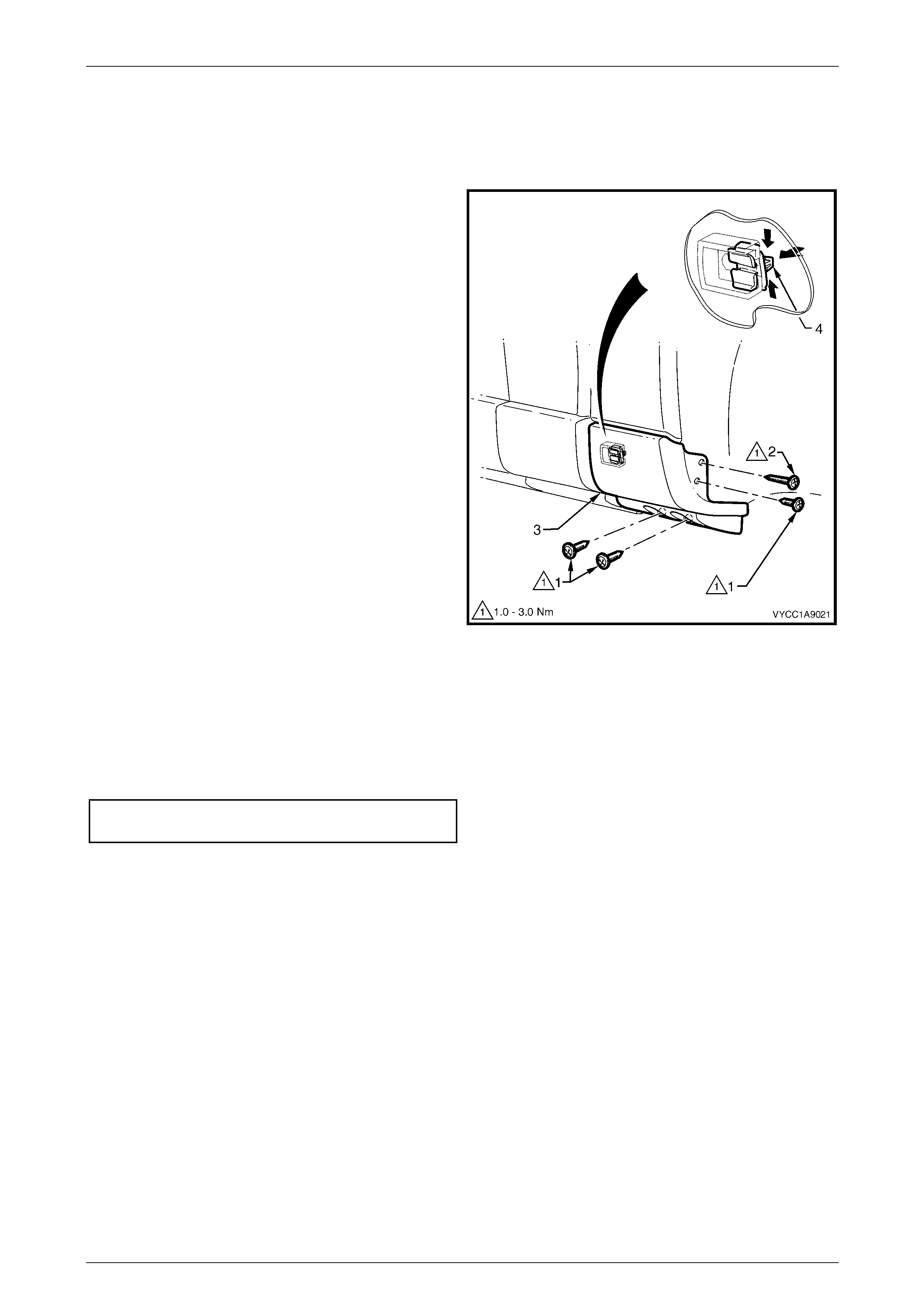
1 Remove the three screws (1) and the longer screw (2)
attaching the rear body front rocker moulding (3) to
the rear body side panel.
2 From behind the body panel, press the retainer clip
tabs (4) together and push the clip out from the panel
to release the rocker moulding.
3 If required, slide the clip out to one side to remove
from the moulding.
Figure 1A9 – 14
Reinstall
1 Slide the clip into place on the moulding if removed
2 Locate and press the moulding onto the panelling.
3 Tighten the screws to the correct torque specification.
Rear body front rocker moulding attaching
screw torque specification.......................... 1.0 – 3.0 Nm
Exterior Ornamentation Page 1A9–20
Page 1A9–20
2.13 Rear Body Rear Rocker Moulding
NOTE
The rear body rear rocker moulding on SS
vehicles is integrated into the rear bumper fascia
assembly. For service procedures on the rear
bumper fascia, refer to Section 1D Bumper Bars.
Remove
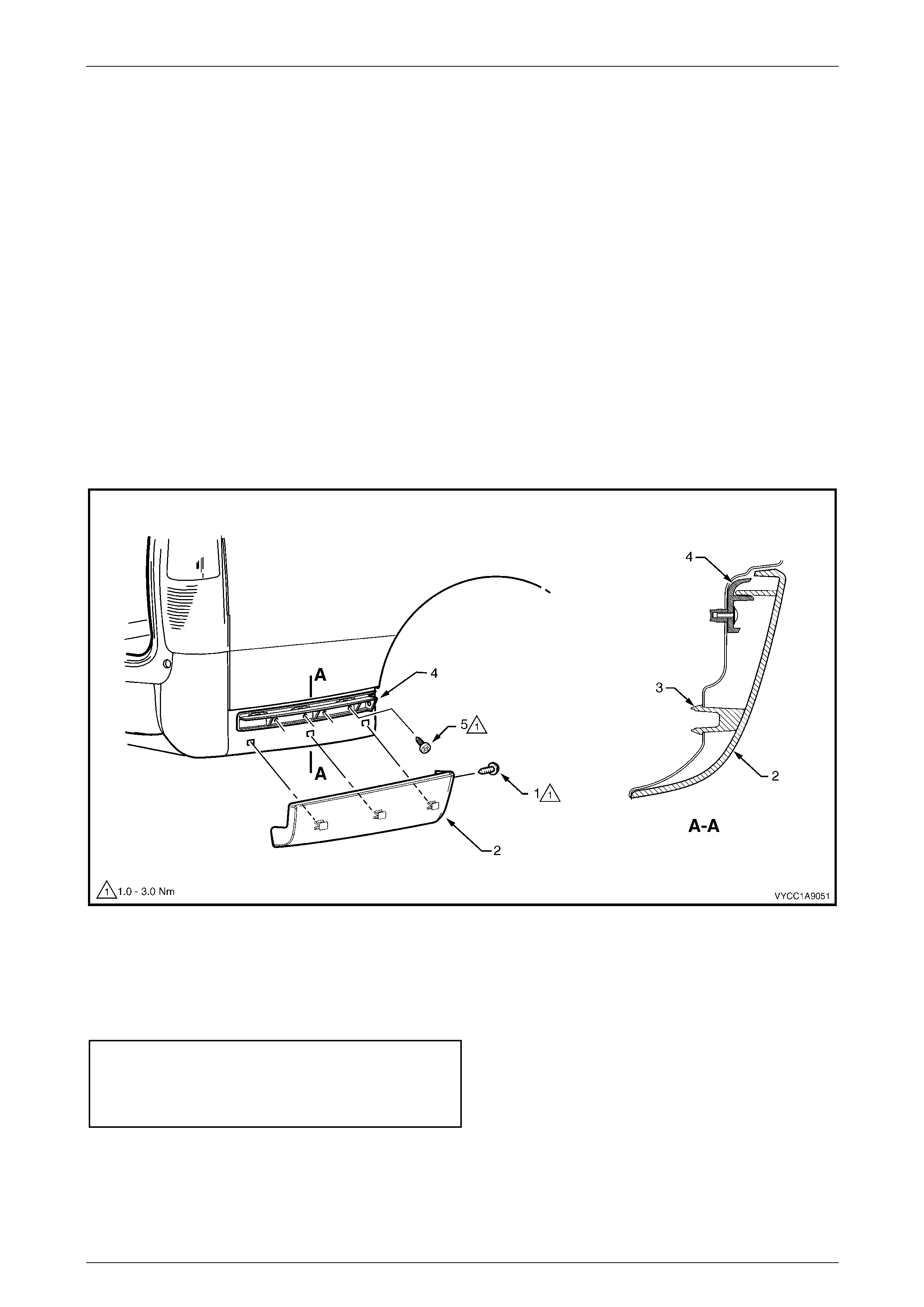
1 Remove the screw (1) attaching the rear body rear rocker moulding (2) to the rear wheelhouse liner, refer to Figure
1A9 – 15
2 From behind the rear quarter panel, press and push out each of the three rocker moulding retaining tangs (3) to
release the rocker moulding from the body panelling.
3 Gently prise the rocker moulding outward from the lower edge to release it from the rear bumper fascia guide
assembly (4).
4 If required, remove the screw (5), four places, attaching the rear bumper facia guide assembly to the panel and
remove the guide assembly.
Figure 1A9 – 15
Reinstall
Reinstallation of the rear body assembly rear rocker moulding is the reverse of the removal procedure. Tighten the
screws the specified torque.
Rear bumper fascia guide assembly
attaching screw torque specification.......... 1.0 – 3.0 Nm
Rear body rear rocker moulding
attaching screw torque specification.......... 1.0 – 3.0 Nm
Exterior Ornamentation Page 1A9–21
Page 1A9–21
2.14 Rear Body Rail Cover
Remove
1 Remove the relevant rear body quarter panel moulding, refer to Section 1A9, 4.13 Quarter Panel Rails in the
MY 2003 VY and V2 Series Service Information.
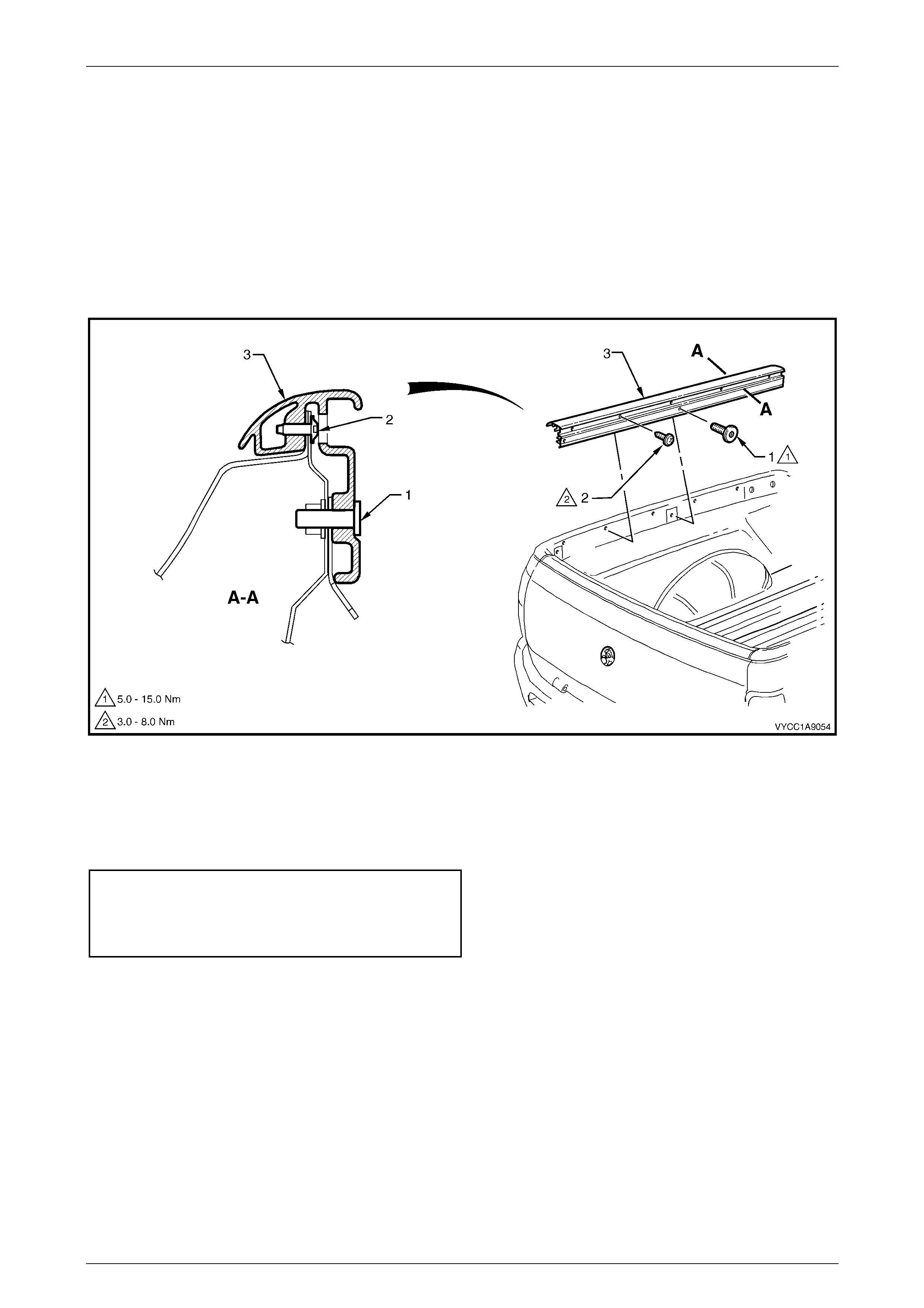
2 Remove the Torx head screw (1), two places, refer to Figure 1A9 – 16.
3 Remove the screw (2), five places, attaching the rear body rail cover (3) to the body.
4 Raise the rear body rail cover slightly at the rear and slide rearwards to release from the front rail cover.
Figure 1A9 – 16
Reinstall
Reinstallation of the rear body rail cover is the reverse of the removal procedure. Tighten the rear body rail cover
attaching screws to the correct torque specification.
Rear body rail cover attaching
screw torque specification.......................... 3.0 – 8.0 Nm
Rear body rail cover Torx-head
attaching screw torque specification........ 5.0 – 15.0 Nm
Exterior Ornamentation Page 1A9–22
Page 1A9–22
2.15 Rear Body Front Rail Cover
Remove
1 Remove the relevant rear body rail cover, refer to 2.14 Rear Body Rail Cover.
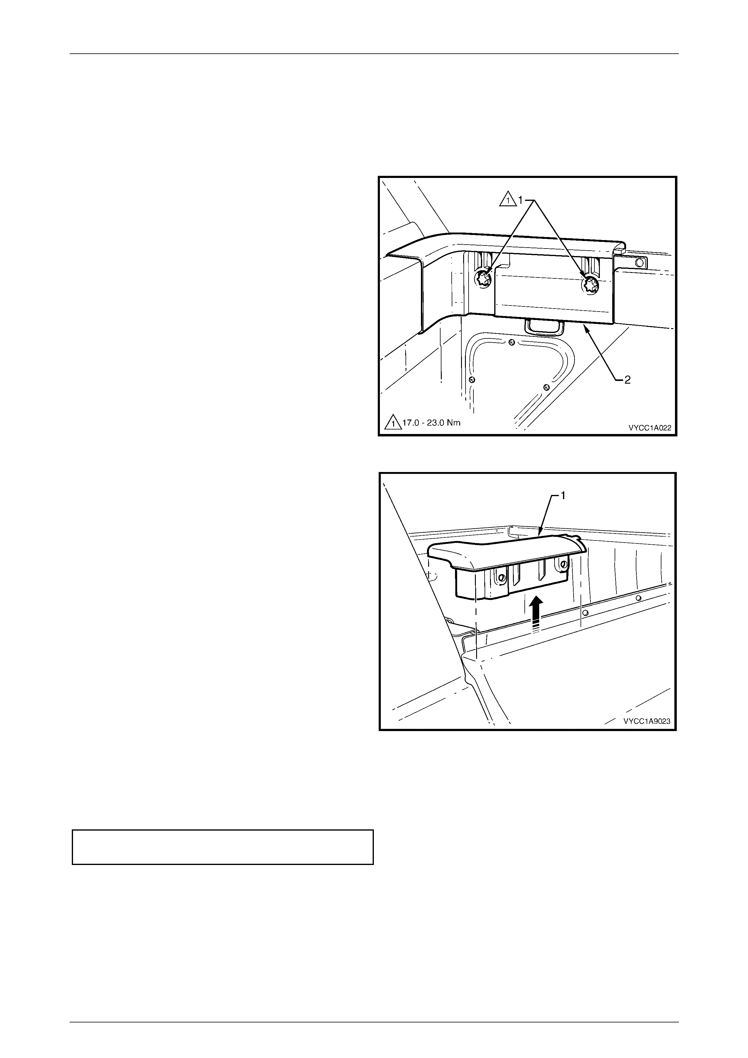
2 Remove the Torx-head bolts (1).
Figure 1A9 – 17
3 Gently lift the rail (1) up from the rear body assembly.
Figure 1A9 – 18
Reinstall
Reinstallation of the rear body front rail cover is the reverse of the removal procedure. Tighten the Torx head screw to
the correct torque specification.
Rear body front rail cover Torx-head
attaching bolt torque specification..........17.0 – 23.0 Nm

Exterior Ornamentation Page 1A9–23
Page 1A9–23
2.16 Emblems and Name Plates
Rear Door Nameplate – SS
Remove
1 Protect the paint and bodywork with tape or a rag.
2 To assist removal, warm the name plate with a heat-
lamp or heat-gun to soften the adhesive.
3 Using a paint scraper or similar, carefully prise the
name plate from the rear door.
4 As required, remove any remaining double-sided tape
from the name plate and/or rear door and clean the
surfaces with Prepsol or equivalent.
Figure 1A9 – 19
Reinstall
1 If reusing the name plate, apply new polyethylene
double-sided tape such as 3M 4428 or equivalent to
the back and trim the edges of the tape slightly in from
the edge of the name plate.
2 Clean the door panel surface with Prepsol or
equivalent.
3 Remove the backing paper from the double-sided
tape.
4 Apply the name plate onto the lower section of the
door panel in the position shown.
5 Press firmly over the entire plate for at least ten
seconds to ensure maximum adhesion.
Figure 1A9 – 20
Exterior Ornamentation Page 1A9–24
Page 1A9–24
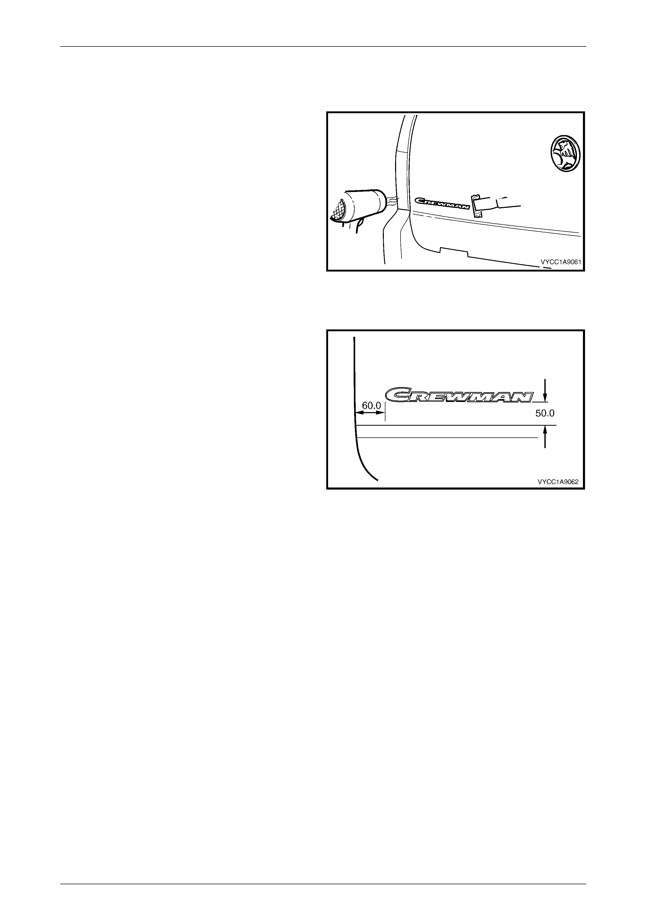
Endgate Nameplate – Crewman
Remove
1 Protect the paint and bodywork with tape or a rag.
2 To assist removal, warm the name plate with a heat-
lamp or heat-gun to soften the adhesive.
3 Using a paint scraper or similar, carefully prise the
name plate from the endgate.
4 As required, remove any remaining double-sided tape
from the name plate and/or endgate and clean the
surfaces with Prepsol or equivalent.
Figure 1A9 – 21
Reinstall
1 If reusing the name plate, apply new polyethylene
double-sided tape such as 3M 4428 or equivalent to
the back and trim the edges of the tape slightly in from
the edge of the name plate.
2 Clean the endgate panel surface with Prepsol or
equivalent.
3 Remove the backing paper from the double-sided
adhesive tape.
4 Apply the name plate onto the left-hand side section
of the tailgate panel in the position shown.
5 Press firmly over the entire name plate for at least ten
seconds to ensure maximum adhesion.
Figure 1A9 – 22
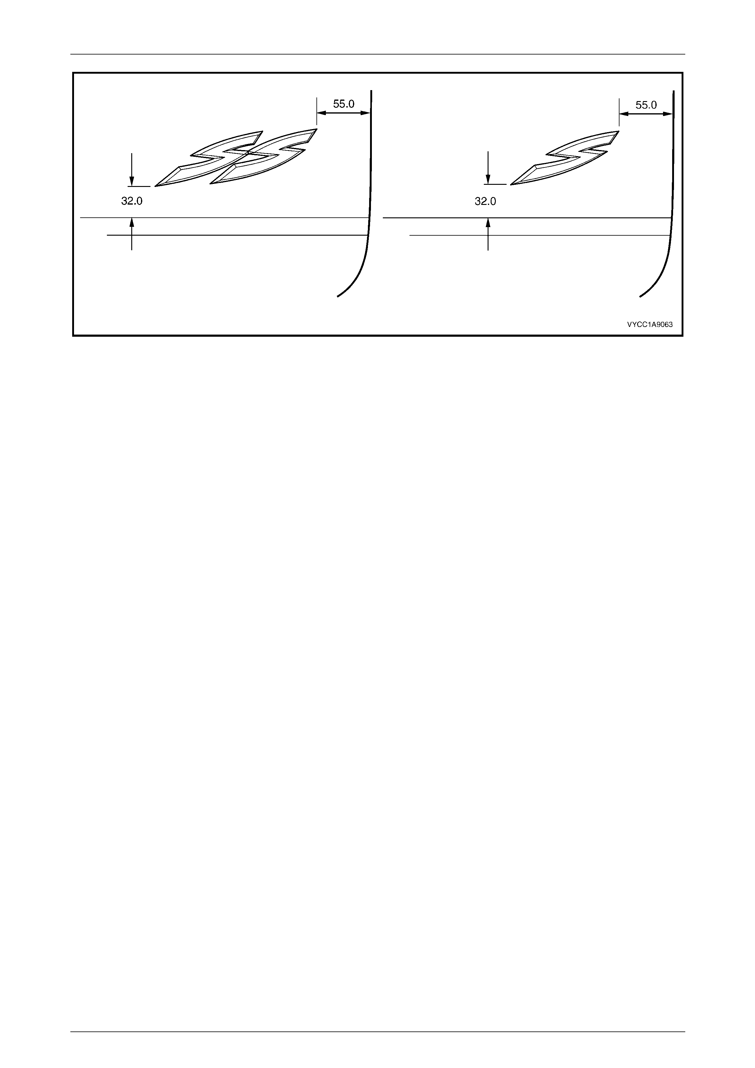
Endgate Nameplate – S and SS
Remove
1 Protect the paint and bodywork with tape or a rag.
2 To assist removal, warm the name plate with a heat-lamp or heat-gun to soften the adhesive, refer
Figure 1A9 – 19.
3 Using a paint scraper or similar, carefully prise the name plate from the endgate.
4 As required, remove any remaining double-sided tape from the name plate and/or endgate and clean the surfaces
with Prepsol or equivalent.
Reinstall
1 If reusing the name plate, apply new polyethylene double-sided tape such as 3M 4428 or equivalent to the back
and trim the edges of the tape slightly in from the edge of the name plate.
2 Clean the endgate surface with Prepsol or equivalent.
3 Remove the backing paper from the double-sided tape.
4 Apply the name plate onto the lower section of the endgate in the position shown, refer Figure 1A9 – 23.
5 Press firmly over the entire plate for at least ten seconds to ensure maximum adhesion.
Exterior Ornamentation Page 1A9–25
Page 1A9–25
Figure 1A9 – 23

Exterior Ornamentation Page 1A9–26
Page 1A9–26
3 Torque Wrench Specifications
Body Lock Pillar Door Moulding Attaching Screw..........................0.3 – 1.0 Nm
Door Opening Moulding Attaching Screw......................................0.3 – 1.0 Nm
Body Lock Pillar Trim Attaching Screw.......................................... 1.0 – 3.0 Nm
Body Lock Pillar Finisher Attaching Screw....................................1.0 – 3.0 Nm
Rear Header Trim Retainer Attaching Screw ................................1.0 – 3.0 Nm
Rear Outer Trim Panel Attaching Screw........................................3.0 – 8.0 Nm
Rocker Panel Moulding Attaching Screw ......................................1.0 – 3.0 Nm
Rear Body Front Rocker Moulding Attaching Screw......................1.0 – 3.0 Nm
Rear Bumper Fascia Guide Assembly Attaching Screw................1.0 – 3.0 Nm
Rear Body Rear Rocker Moulding Attaching Screw......................1.0 – 3.0 Nm
Rear Body Rail Cover Attaching Screw .......................................3.0 – 8.0 Nm
Rear Body Rail Cover Torx-Head Attaching Screw ....................5.0 – 15.0 Nm
Rear Body Front Rail Cover Torx-Head Attaching Bolt .............17.0 – 23.0 Nm