
Sheetmetal and Subfram e Page 1B–1
Page 1B–1
Section 1B
Sheetmetal and Subfram e
ATTENTION
Before performing any Service Operation or other procedure described in this Section, refer to Section 00
Warnings, Cautions and Notes for correct workshop practices with regard to safety and/or property damage.
1 General Information............................................................................................................................... 2
2 Service Operations – Crew Cab ........................................................................................................... 3
2.1 Body Structure Replacement Parts ......................................................................................................................3
Underbody ..............................................................................................................................................................4
Upperbody Sheetmetal..........................................................................................................................................6
Body Assembly ......................................................................................................................................................8
Rear Tray Body Assembly...................................................................................................................................10
2.2 Rear Tray Body Assembly...................................................................................................................................12
Remove .................................................................................................................................................................13
Reinstall ................................................................................................................................................................14
2.3 Inner Side Panel Extension Cover......................................................................................................................16
Remove .................................................................................................................................................................16
Reinstall ................................................................................................................................................................16
2.4 Front End Panel Cover.........................................................................................................................................17
Remove .................................................................................................................................................................17
Reinstall ................................................................................................................................................................17
2.5 Subframe Assembly.............................................................................................................................................18
Remove .................................................................................................................................................................18
Disassemble.....................................................................................................................................................19
Reassemble......................................................................................................................................................19
Reinstall ................................................................................................................................................................20
3 Torque Wrench Specifications........................................................................................................... 23

Sheetmetal and Subfram e Page 1B–2
Page 1B–2
1 General Information
With the following exceptions, MY 2004 VY Regular Cab and Crew Cab Sheetmetal and Rear Subframe information
carries over from MY 2004 VY Series vehicles and MY 2003 VY Regular Cab vehicles.
Crew Cab:
• Body structure replacement parts
• Rear tray body assembly
• Inner side panel ex tension cover
• Front End panel cover
• Subframe Assembly
For information not contained within this Section, refer to Section 1B Sheetmetal in the MY 2004 VY and V2 Series
Service Information and Section 1B Sheetmetal and Rear Subframe in the MY 2003 VY Regular Cab Service
Information.
Endgate service information carries over from the MY 2004 VY Utility. For all endgate service information, refer to
Section 1A4 Hood, Rear Compartment Lid, Liftgate and Endgate in the MY 2004 VY and V2 Series Service Information.
The MY 2004 VY Crew Cab rear tray body assembly is attached to the subframe assembly using six mounting points
and has an additional four supports attached to the subframe and body assembly. Figure 1B – 5 illustrates the locations
of these mounting points and the shows a detailed view of the supports.

Sheetmetal and Subfram e Page 1B–3
Page 1B–3
2 Service Operations – Crew Cab
2.1 Body Structure Replacement Parts
The following illustrations and tables describe the Crew Cab body structure assemblies and panels that are available for
se rvice replacement.
The purpose of this information is to provide the repairer with a better understanding of available replacement sections.
For further information regarding the body structure, refer to the VY Regular Cab and Crew Cab Service Information
Supplement, Body Structure Repair.
Sheetmetal and Subfram e Page 1B–4
Page 1B–4
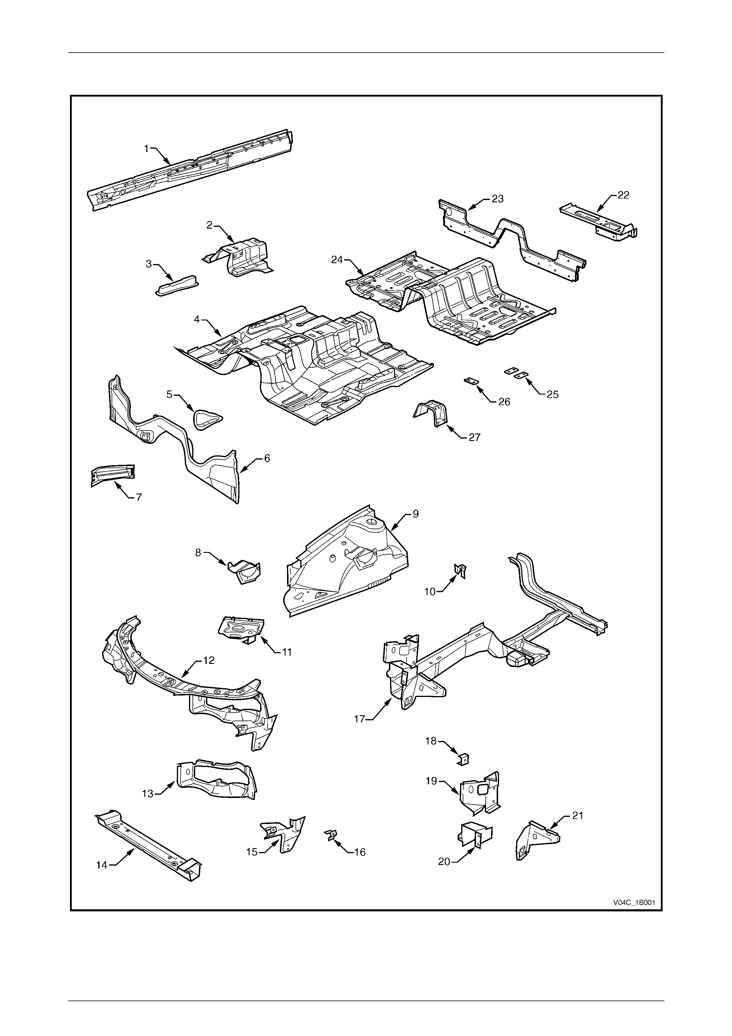
Underbody
Figure 1B – 1

Sheetmetal and Subfram e Page 1B–5
Page 1B–5
Legend
1 Inner Rocker P anel Assembl y
2 Seat Inner Bracket Assembly
3 Seat Outer Bracket Ass embly, RH/ LH
4 Front Floor Panel Assembly
5 Transmission Support Bracket, LH/ RH
6 Front Floor Panel Extension
7 Front Side Rail Brace, RH/ LH
8 ABS Modulator Bracket Assembly
9 Front Wheelhouse Panel Assembly
10 Horn Bracket Assembly
11 Battery Tray Assembly
12 Front End Panel Assembly
13 Headlamp Panel, LH/ RH
14 Radiator Lower Support Ass em bly
15 Headlamp & Front Fascia Mount Bracket, LH/ RH
16 Fender Front Lower Bracket, LH/ RH
17 Front Side Rail Assembly, LH/ RH
18 Radiator Side Mounting B rack et, LH/ RH
19 Front Wheelhouse Bracket Assembly, LH/ RH
20 Front Bumper Impact Bar Bracket, LH/ RH
21 Front Wheelhouse Panel Bracket, LH/ RH
22 Rear Lower Body Panel Assem bly, LH/ RH
23 Rear Lower Body Panel
24 Front Floor Panel Extension Assembly
25 Floor Panel Plate Assembly, 2 each LH/ RH
26 Rear Seatbelt Anchor Plat e Assembly, 3 places
27 Propeller Shaft Hanger Assembly
Sheetmetal and Subfram e Page 1B–6
Page 1B–6
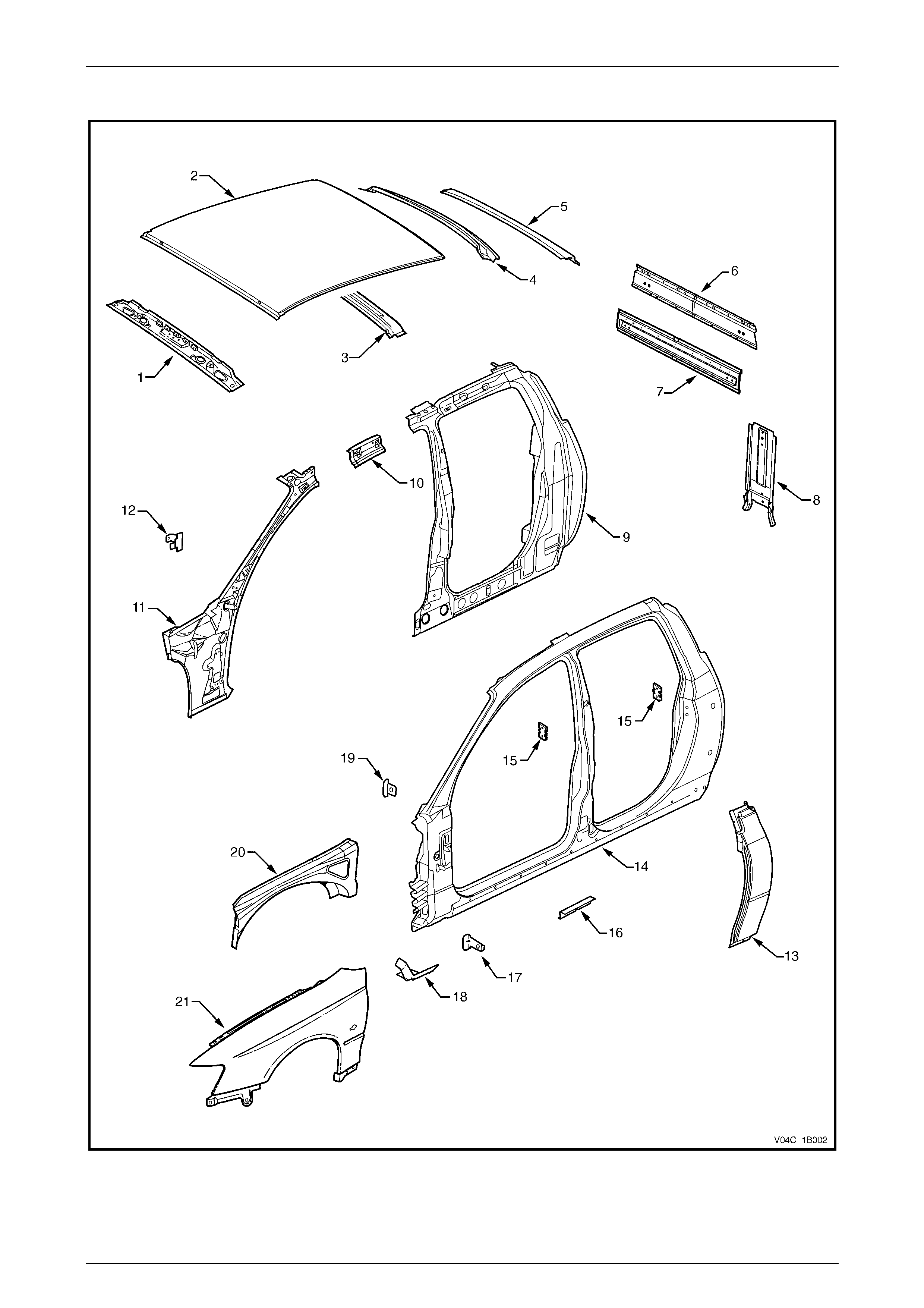
Upperbody Sheetmetal
Figure 1B – 2

Sheetmetal and Subfram e Page 1B–7
Page 1B–7
Legend
1 Roof Front Header Panel
2 Roof Panel
3 Roof Bow Panel
4 Roof Rear Header Inner Panel
5 Roof Rear Header Outer Panel
6 Rear Body Upper Outer Panel Assembly
7 Rear Body Upper Inner Panel Assembly
8 Rear Body Lower Panel Assem bly
9 Quarter Panel Inner Assembl y
10 Quarter Panel Inner Extensi on
11 Hinge Pillar Inner Panel Assembly
12 Hinge Pillar Trim Panel Bracket
13 Quarter Panel
14 Door Opening Frame Assembly
15 Door Striker Anchor Plate
16 Underbody Jack i ng Locator
17 Fender Rear Bracket
18 Fender Lower Rear Bracket
19 Fender Upper Rear Bracket
20 Front Wheelhouse Panel Upper Side Rail
21 Front Fender
Sheetmetal and Subfram e Page 1B–8
Page 1B–8
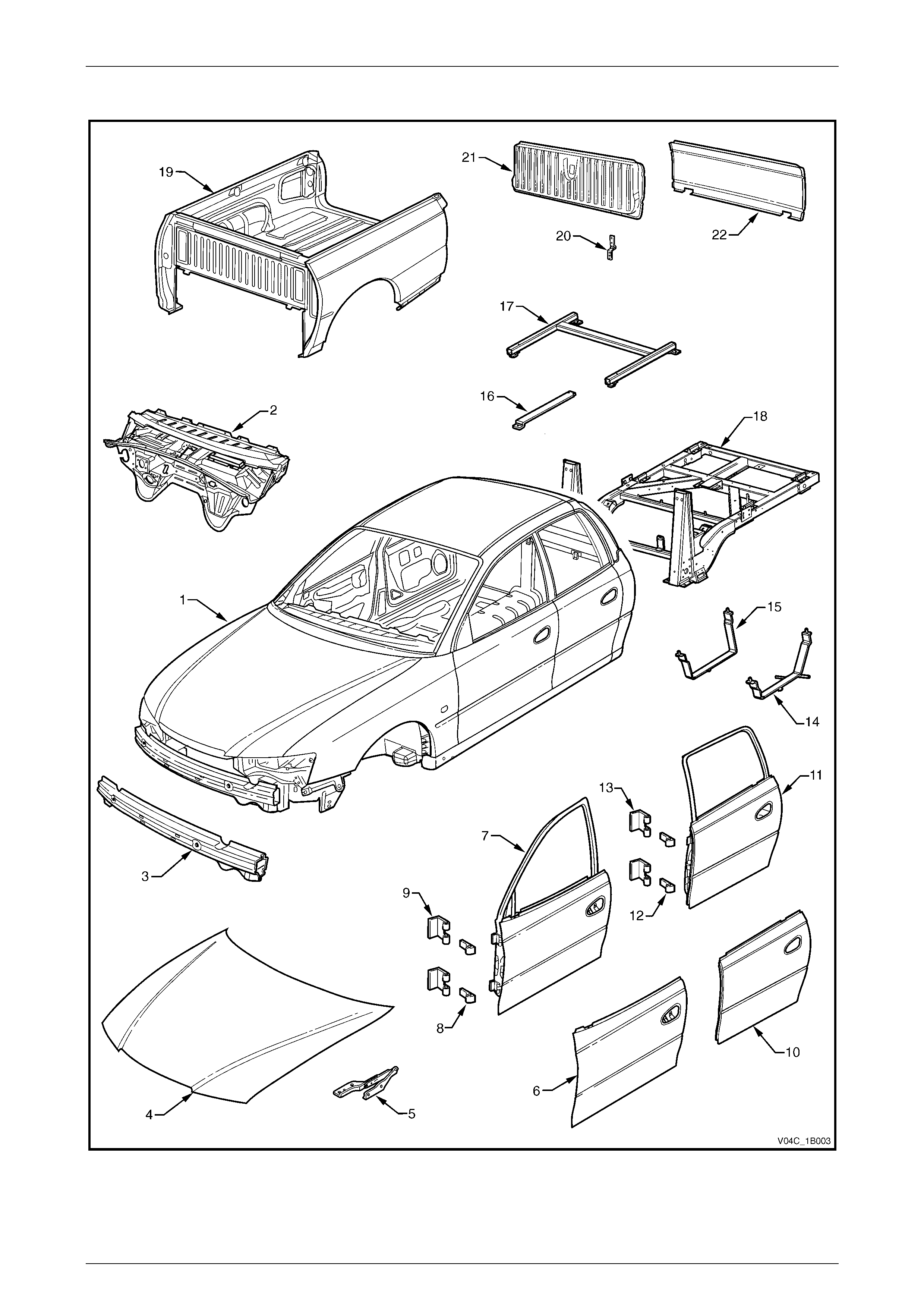
Body Assembly
Figure 1B – 3

Sheetmetal and Subfram e Page 1B–9
Page 1B–9
Legend
1 Body Assembly
2 Dash Panel Assembly
3 Front Bumper Impact Bar Assembly
4 Hood Assembly
5 Hood Hinge Assembly
6 Front Door Outer Panel
7 Front Door Assembly
8 Front Door Hinge (door side)
9 Front Door Hinge (body side)
10 Rear Door Outer Panel
11 Rear Door Assembl y
12 Rear Door Hinge (door side)
13 Rear Door Hinge (body side)
14 Fuel Tank Lower Strap, LH
15 Fuel Tank Lower Strap, RH
16 Fuel Tank Upper Strap LH/ RH
17 Floor Support Frame
18 Subframe Assembly
19 Rear Tray Body Assembly
20 Endgate Hinge Assembly
21 Endgate Assembly
22 Endgate Outer Panel
Sheetmetal and Subfram e Page 1B–10
Page 1B–10
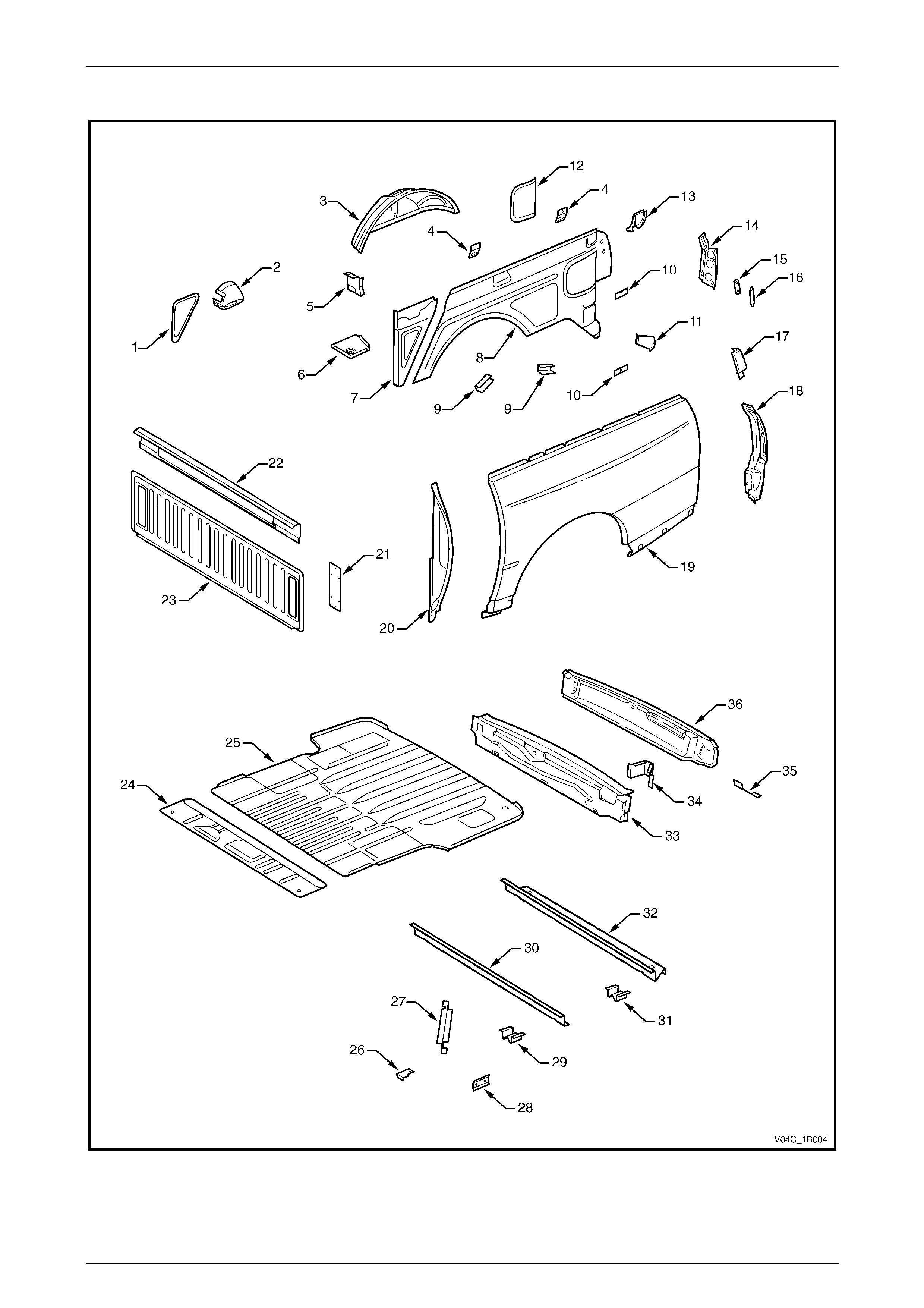
Rear Tray Body Assembly
Figure 1B – 4

Sheetmetal and Subfram e Page 1B–11
Page 1B–11
Legend
1 Inner Side Panel Extension Cover, RH
2 Fuel Filler Pipe Housing, RH
3 Rear Wheelhouse Inner Panel
4 Cargo Tie Down Bracket
5 Front Cover Attachment B eam
6 Load Floor Panel Front Extension
7 Inner Side Panel Extension Assem bly
8 Inner Side Panel
9 Wheelhouse Filler Panel Bracket
10 Cargo Tie Down Bracket Anchor Plate Assembly
11 Quarter Panel Rear Brace
12 Rear Inner Side Panel Cover
13 Quarter Lower Rear Panel
14 Quarter Inner Lower Rear Extension
15 Endgate Striker Anchor Plate
16 Endgate Striker Anchor Plate Retainer
17 Quarter Panel Upper Extension
18 Quarter Panel Extension
19 Rear Quarter Panel
20 Quarter Panel Front Gusset
21 Front End Panel Cover
22 Front End Panel Sill Assembly
23 Front End Panel
24 Load Floor Front Extension
25 Load Floor Panel
26 Front End Panel Locator
27 Load Floor Panel Support
28 Load Floor Panel Side Support
29 Load Floor Panel Locator
30 Load Floor Panel Front Support
31 Load Floor Panel Locator Guide
32 Load Floor Panel Rear Support
33 Rear End Panel
34 Endgate Hinge Reinforcement
35 Rear Fascia Centre Bracket
36 Rear End Lower Panel

Sheetmetal and Subfram e Page 1B–12
Page 1B–12
2.2 Rear Tray Body Assembly
Figure 1B – 5
Sheetmetal and Subfram e Page 1B–13
Page 1B–13
Remove
1 Disconnect the wiring harness at the rear of the cab, refer to Section 12A Battery & Cables.
2 Remove the fuel filler neck, refer to Section 8A1, 2.2 Fuel Filler Neck and Splash Guard.
3 Remove the mounting bolt (1), 2 places each side of
the vehicle, attaching the rear tray body assembly to
the subframe centre moun t (2) .
Figure 1B – 6
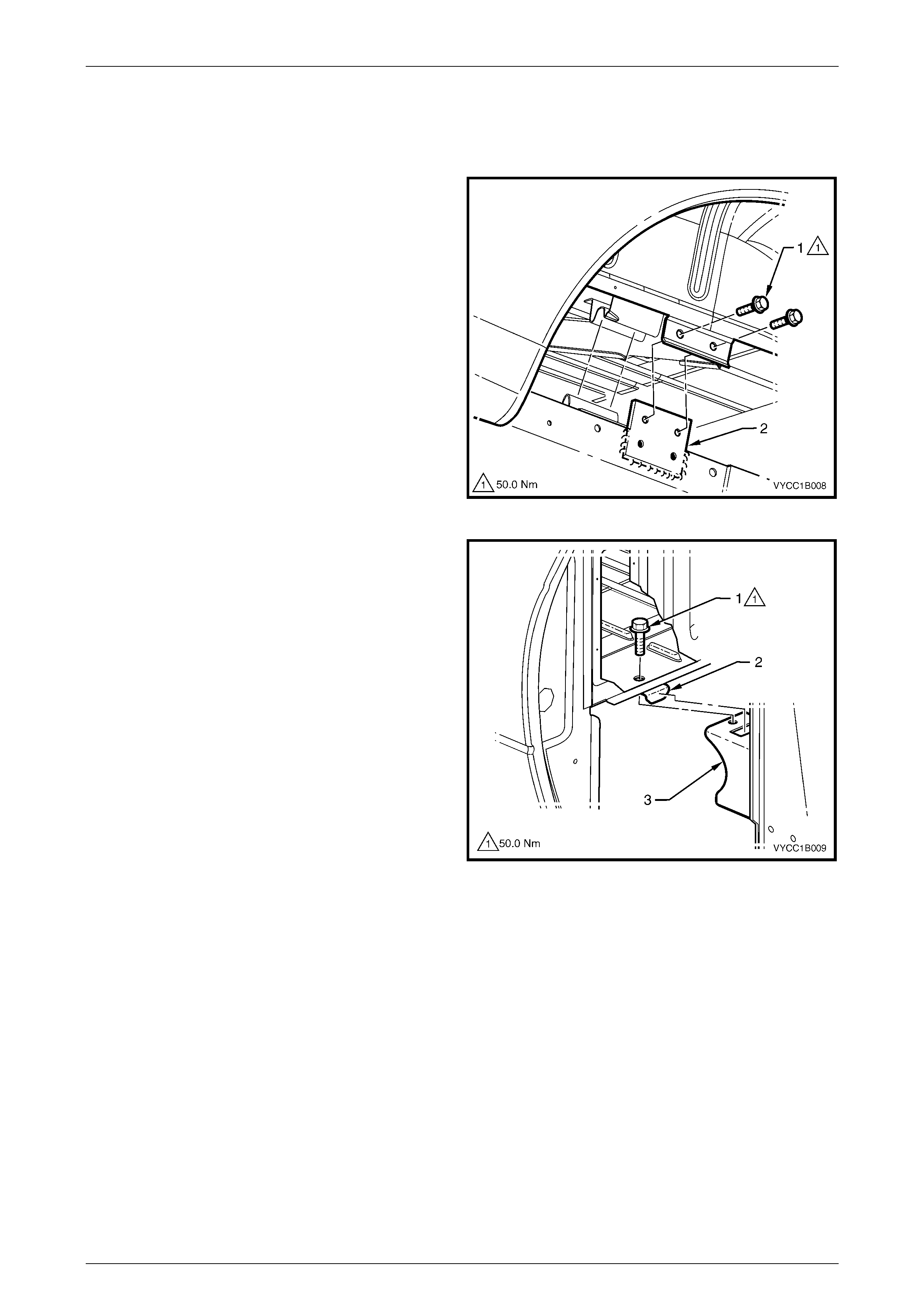
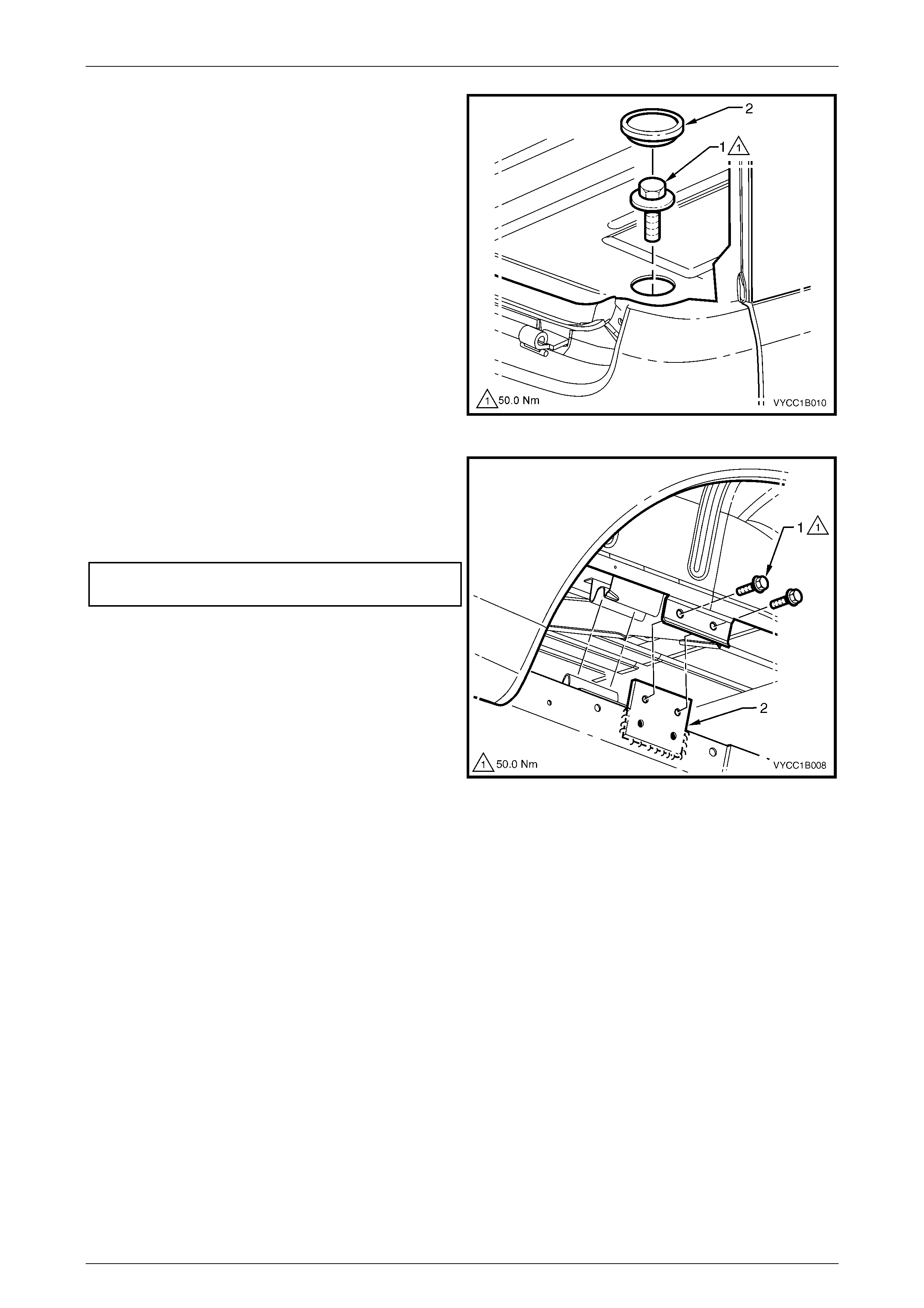
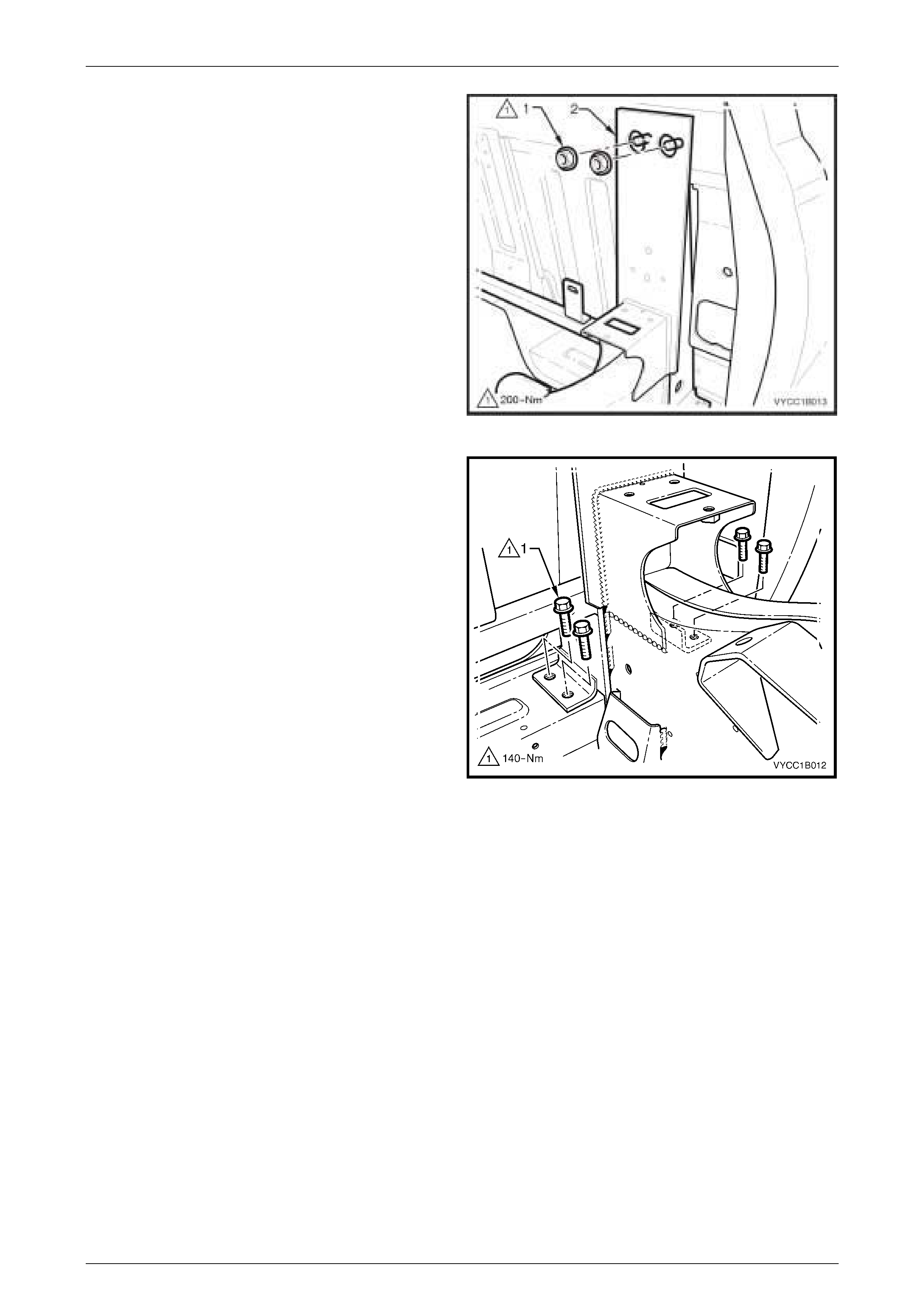
4 Remove the bolt (1), one place each side attaching
each front corner of the body assembly (2) to the
subframe (3).
Figure 1B – 7
Sheetmetal and Subfram e Page 1B–14
Page 1B–14
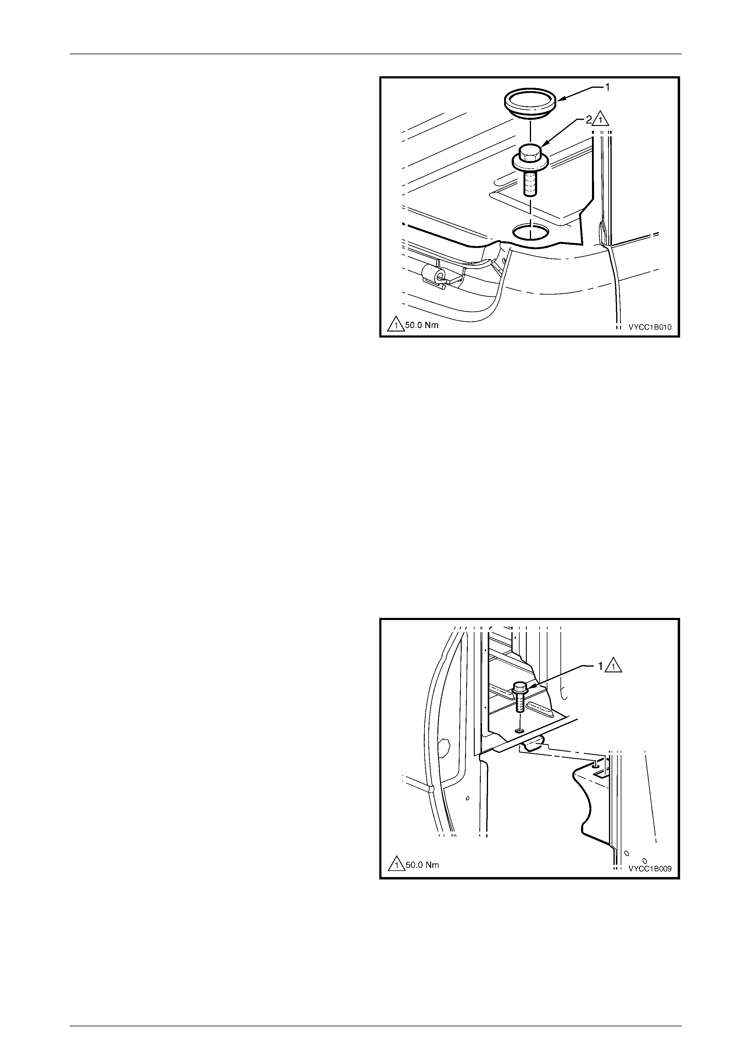
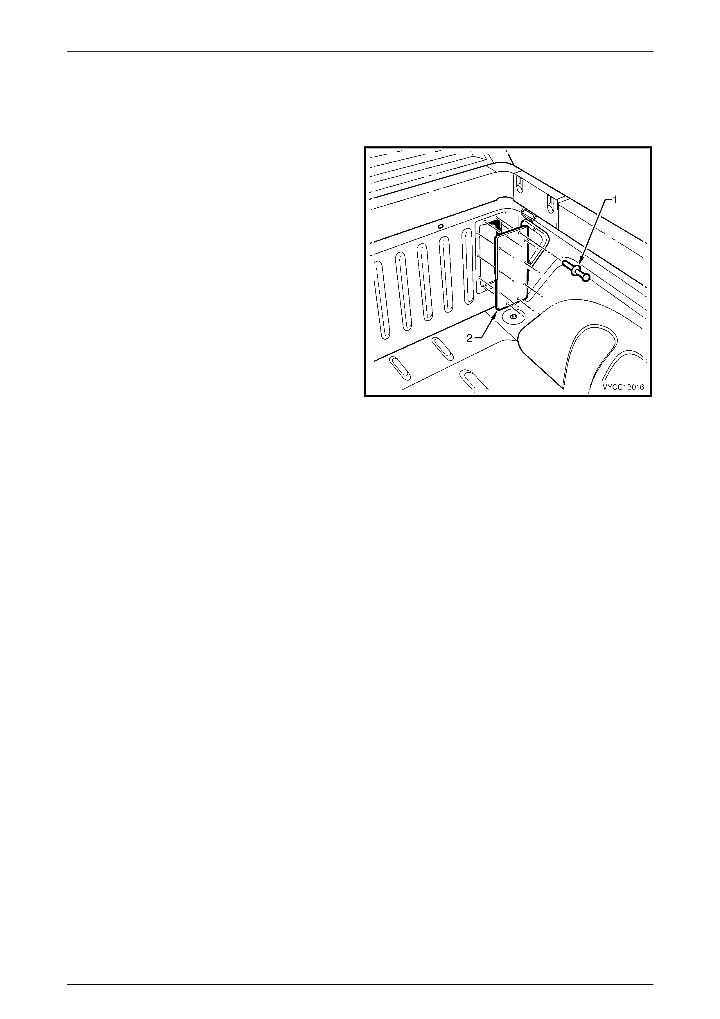
5 Remove the grommet (1), one place each side to allow
access to the mounting bolt (2).
6 Remove the bolt, one place each side attaching each
rear corner of the body assembly to the subframe.
7 With the aid of several assistants or using a suitable
lifting hoist, carefully raise the body assembly clear of
the vehicle and remove.
Figure 1B – 8
Reinstall
NOTE
The floor support frame has strips of foam glued
to it. If the foam is damaged, replace it with
commercially available high-density foam and fix
with contact adhesive.
1 With the aid of several assistants or using a suitable lifting hoist, carefully position the rear tray body assembly over
the subframe.
NOTE
Ensure the front location tab is positioned in the
slot of the front subframe mount correctly.
2 Slide the tray as far forward as possible, then reinstall
the bolt (1), one place in each front corner, but do not
tighten.
Figure 1B – 9
Sheetmetal and Subfram e Page 1B–15
Page 1B–15
3 Reinstall the bolt (1), one place in each rear corner,
but do not tighten. Do not install the grommet (2) at
this stage.
Figure 1B – 10
4 Reinstall the two bolts (1) in the centre mount (2),
each side of the vehicle, but do not tighten.
5 Ensure the rear body is positioned correctly on all
mounting points and tighten all fixtures to the specified
torque.
Rear tray body assembly mounting bolt
torque specific atio n ...........................................50.0 Nm
6 Reinstall the grommet (2), one place each side in the
rear body floor, refer to Figure 1B – 10.
7 Refit the fuel filler neck, refer to Section 8A1, 2.2 Fuel
Filler Neck and Splash Guard.
8 Reconnect the wiring harness at the rear of the body,
refer to Section 12A Battery & Cables.
9 Ensure all lights are working correctly.
Figure 1B – 11
Sheetmetal and Subfram e Page 1B–16
Page 1B–16
2.3 Inner Side Panel Extension Cover
Remove
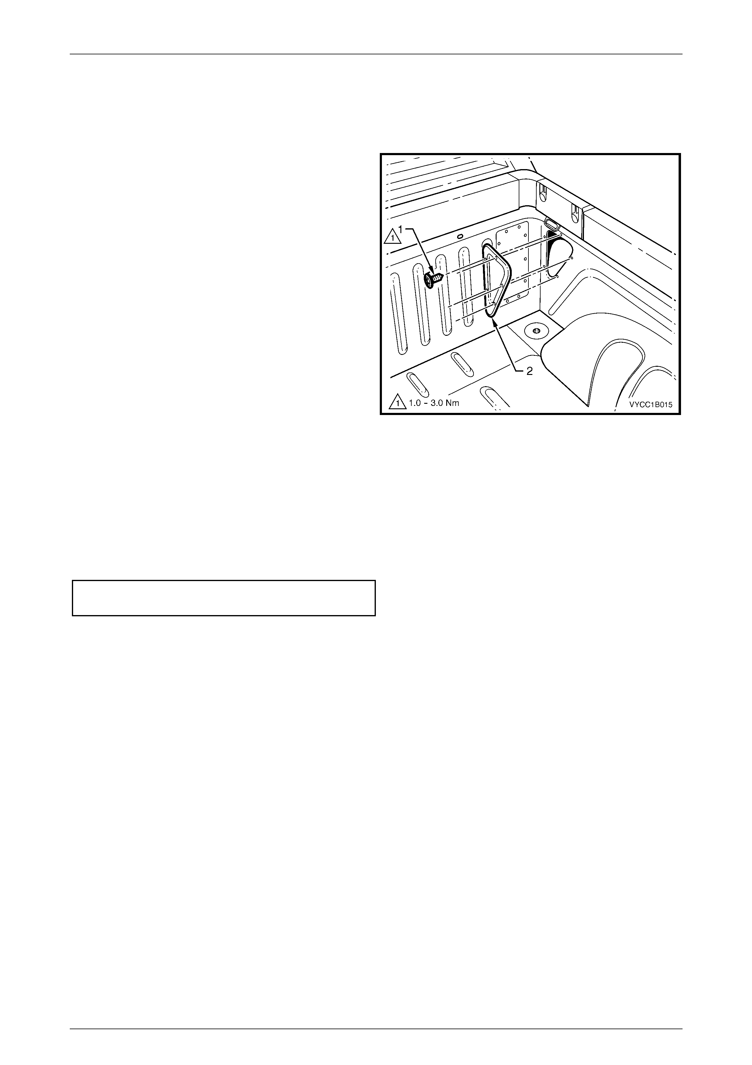
1 Remove the screw (1) five places, attaching the inner
side panel extension cover (2).
NOTE
Protect the paintwork with a rag when performing
the following operation.
2 Using a flat-blade screwdriver or suitable lever,
carefully prise the corner of the cover from the inner
side panel to break the sealer.
3 Remove t he cover .
Figure 1B – 12
Reinstall
1 Clean off any old sealer and ensure the cover and inner side panel are clean and dry.
2 Apply a continuous bead of sealer such as non-hardening butyl sealer around the perimeter of the cover.
3 Install the cover ensuring it is correctly orientated.
4 Start all screws and then, tighten to the specified torque.
Inner side panel ex tension cover attachi ng
screw torque specification.......................... 1.0 – 3.0 Nm
5 Remove any residual sealer as required.
Sheetmetal and Subfram e Page 1B–17
Page 1B–17
2.4 Front End Panel Cover
Remove
1 Remove the 10 pop rivets (1) attaching the front end
panel cover (2) to the front end panel by drilling the
heads of the rivets.
NOTE
Use a rag to avoid damage to the front end
panel or paintwork when removing the front end
panel cover.
2 Using a flat-blade screwdriver, carefully prise the
corner of the cover from the front end panel to break
the sealer.
3 Remove t he cover .
Figure 1B – 13
Reinstall
1 If required, clean off any old sealer and ensure the front end panel cover and front end panel are clean and dry.
2 Apply a continuous bead of sealer such as non-hardening butyl sealer around the perimeter of the cover.
3 Install the cover ensuring it is correctly orientated and attach with new pop rivets
4 Remove any residual sealer as required.

Sheetmetal and Subfram e Page 1B–18
Page 1B–18
2.5 Subframe Assembly
Any collision that has damaged the subframe assembly to the extent that it needs to be replaced may, have caused
some deformation to the cab structure and a complete thorough inspection and a dimensions check of the cab bodywork
is recommended.
Where a replacement of the subframe assembly is required, ancillary components will need to be removed from the
subframe. In this case it may be more convenient for the technician to remove these components while the subframe
assembly is still assembled to the vehicle.
The vehicle may become unbalanced on
stands or a hoist once the subframe
assembly, rear axle or rear suspension is
removed. Ensure the cab and subframe are
supported sufficiently to avoid injury or
damage before proceeding.
Remove
1 If required, remo ve the rear tray body assembly, refer to 2.2 Rear Tray Body Assembly.
2 Disconnect and plug the fuel lines at the connectors located just behind the cab and, if required, remove the fuel
tank, refer to Section 8A1 Fuel Tank.
3 Disconnect the handbrake cable and brake lines, refer to Section 5A Service & Park Braking System.
4 If fitted, disconnect the rear ABS sensor leads, refer to Section 5B ABS.
5 Remove the rear and intermediate exhaust assemblies, refer to Section 8B Exhaust System.
NOTE
Once the propeller shaft has been removed from
the transmission, it may be necessary to fit a
blanking plug into the rear of the transmission to
prevent any loss of transmission fluid.
6 Remove the propeller shaft, refer to Section 4C Propeller Shaft and Universal Joint.
NOTE
Removal of the rear suspension and axle
assemblies is not a mandatory requirement for
the removal of the subframe assembly. The rear
suspension and axle assembly may if required,
be removed from the subframe assembly as a
complete unit. If removed, support the subframe
with a suitable jack or lifting crane.
7 If required, remove the rear axle assembly, refer to Section 4B Rear Axle.
8 If required, remove the rear suspension assembly, refer to Section 4A Rear Suspension.
9 Remove the outer trim panel and noise reduction foam from between the subframe mounts and the cab, refer to
Section 1A9, 2.10 Rear Outer Trim Panel and NVH Foam.
Sheetmetal and Subfram e Page 1B–19
Page 1B–19
10 Remove the two flange nuts (1), either side, attaching
the subframe assembly (2) to the cab.
Figure 1B – 14
11 Remove the lower bolt (1), four plac es each side of the
vehicle.
12 With the aid of an assistant, remove the subframe
assembly from the cab by either, lifting or rolling it
clear of the cab.
Figure 1B – 15
Disassemble
If not already removed, as required remove the following:
1 Remove the fuel tank, carbon canister, fuel filler neck, lower fuel tank straps, heat shield and the remaining fuel
and vapour lines attached to the subframe, refer to Section 8A1 Fuel Tank.
2 Remove the brake proportioning valve and the remaining rear brake lines, refer to Section 5A Service & Park
Braking System.
3 Remove the rear axle assembly, refer to Section 4B Final Drive and Drive Shafts.
4 Remove the rear suspension, shock absorbers and bump stops, refer to Section 4A Rear Suspension.
5 Remove the spare wheel winch, refer to Section 10 Wheels & Tyres.
Reassemble
1 Reassemble the subframe components in the reverse order of the disassemble process. Follow the assembly
procedures in the Sections referred to for the relevant components.
Sheetmetal and Subfram e Page 1B–20
Page 1B–20
Reinstall
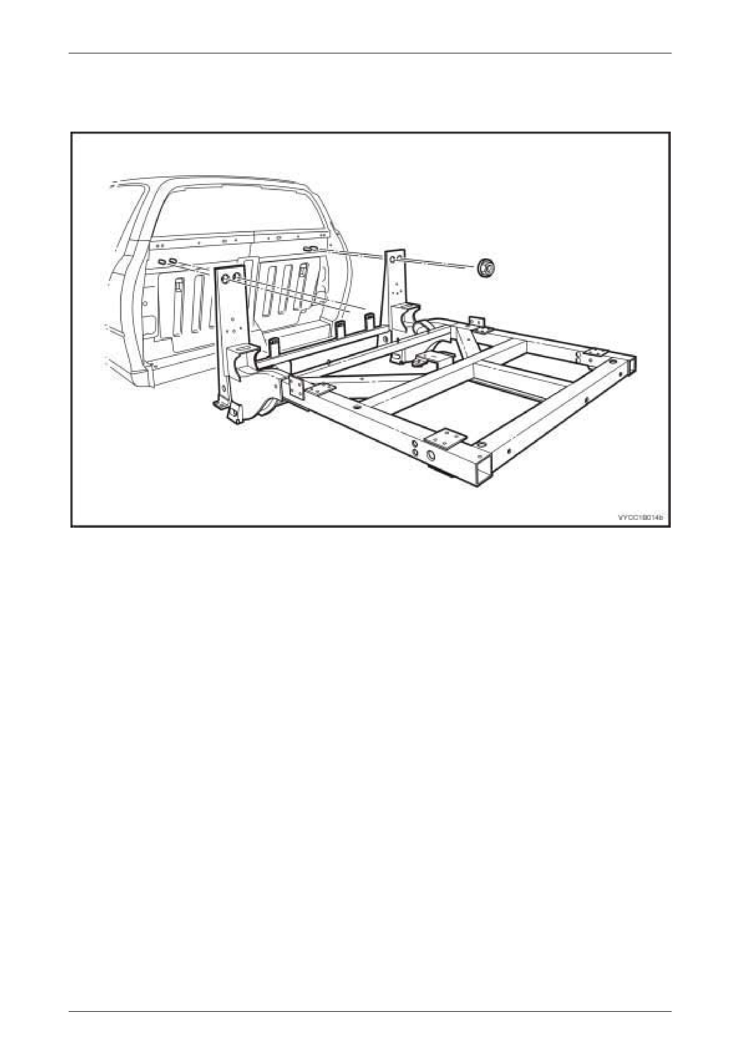
1 With the aid of an assistant and using a suitable jack or lifting device, align the subframe assembly squarely to the
cab and position the subframe on to the mating surfaces of the cab lower cross member, refer to Figure 1B – 16.
Figure 1B – 16
2 Slide the subframe forward until the upper face contacts the back of the cab.
Sheetmetal and Subfram e Page 1B–21
Page 1B–21
Ensure new subframe stud plates, mounting
bolts and nuts are used when reinstalling the
rear subframe. When installing the new
attaching nuts and bolts do not use any
sealers or thread locking compounds on the
bolts, nuts or between the joints on the
subframe mounts.
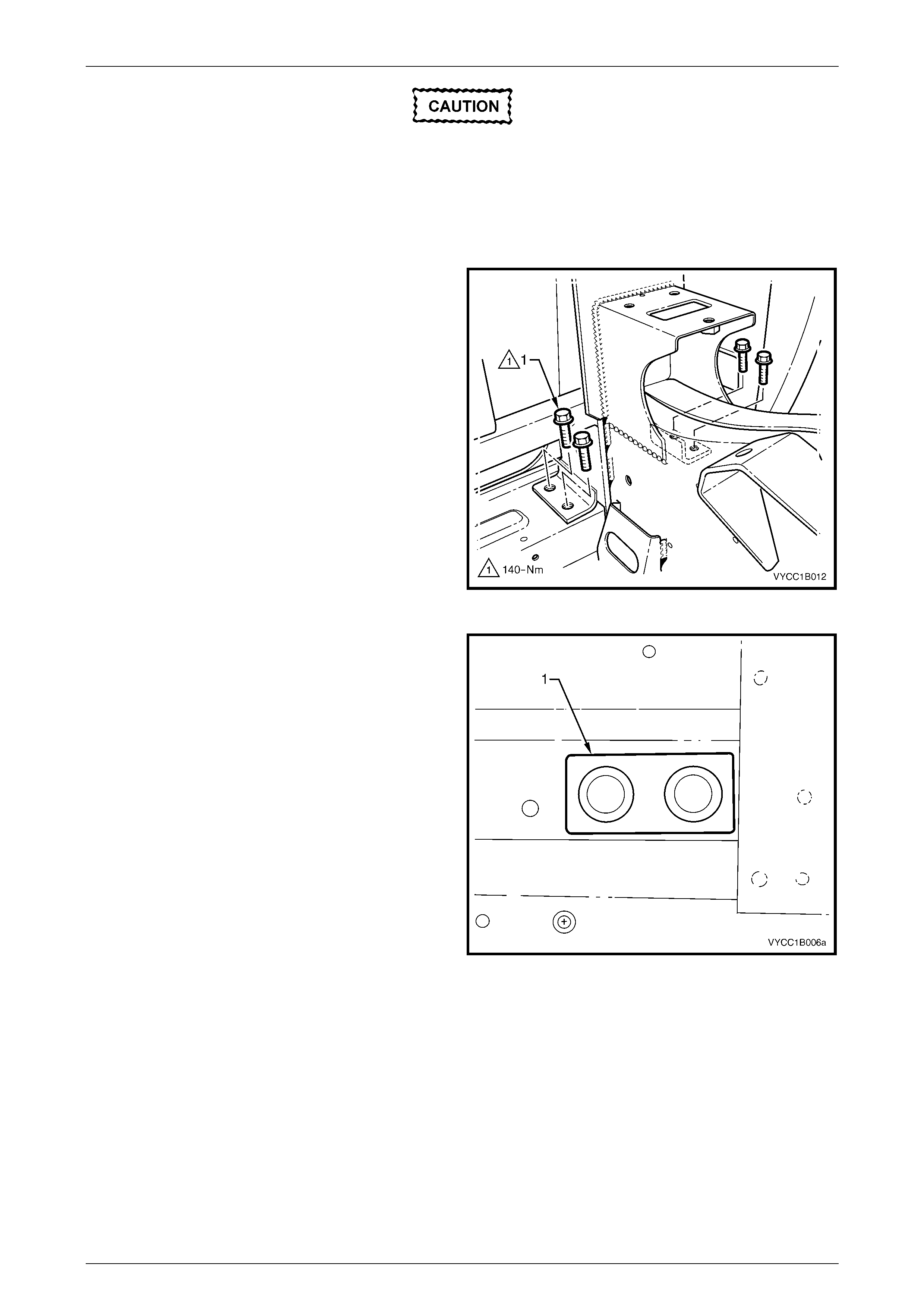
3 Insert the new lower bolt (1), four places each side of
the vehicle, but do not tighten.
Figure 1B – 17
4 If removed, from inside the vehicle reinstall the stud
plate (1) through the rear body upper panel, one place
each side of the vehicle.
Figure 1B – 18
Sheetmetal and Subfram e Page 1B–22
Page 1B–22
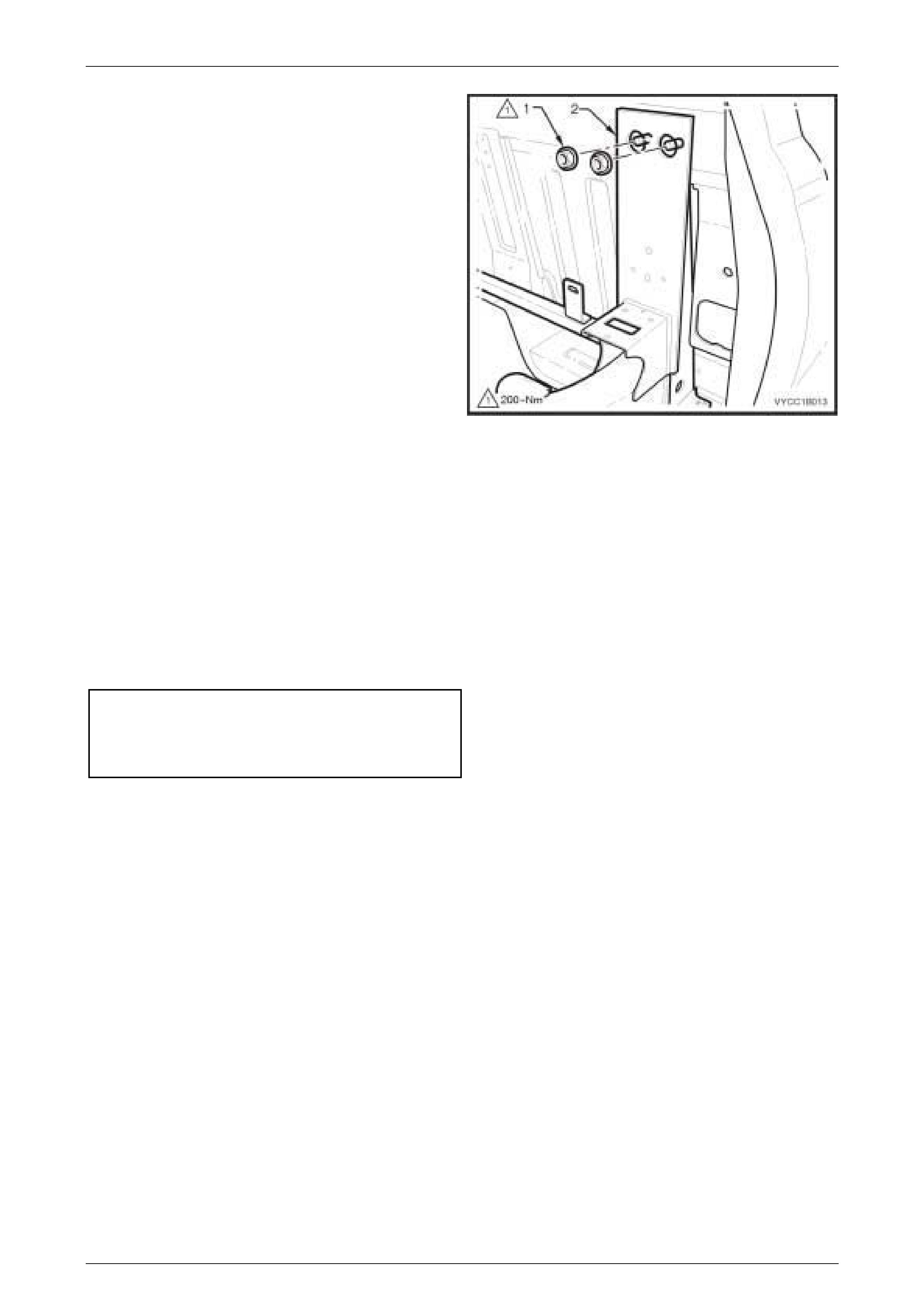
5 Install the two new top flange nuts (1), either side,
attaching the subframe assembly (2) to the cab, but do
not tighten.
Figure 1B – 19
NOTE
Support the subframe assembly so that the
weight of the subframe does not hang on the
mounting points causing an adverse effect on the
tightening of the bolt s.
6 Initially tighten all mounting fixtures to obtain the correct location of the subframe assembly, ensuring there are no
gaps at the mounting points to the cab.
7 Tighten the four lower mounting bolts in a diagonal pattern to the specified torque, repeat for the other side of the
vehicle.
8 Tighten the two top mounting nuts to the specified torque, repeat for the other side of the vehicle.
Subframe assembly lower attaching bolt
torque specific atio n .........................................140.0 Nm
Subframe assembly top stud plate nut
torque specific atio n .........................................200.0 Nm
9 To ensure correct alignment of the subframe to the cab, it is recommended that a check of the body dimensions be
performed, refer to Section 1A2 Body Dimensions.
10 Reinstall the remaining components in the reverse order to removal, referring to the appropriate Sections.
NOTE
To ensure that the vehicle’s steering and
handling is at its optimum performance, it is
recommended that a wheel alignment be
performed after the subframe assembly has been
removed and refitted, refer to Section 3 Front
Suspension.

Sheetmetal and Subfram e Page 1B–23
Page 1B–23
3 Torque Wrench Specifications
Rear Tray Body Assembly Mounting Bolt .............................................50.0 Nm
Inner Side Panel Extension Cover Attaching Screw......................1.0 – 3.0 Nm
Subframe Assembly Lower Attaching Bolt..........................................140.0 Nm
Subframe Assembly Top Stud Plate Attaching Nut.............................200.0 Nm