
Bumper Ba r s Page 1D–1
Page 1D–1
Section 1D
Bumper Bars
ATTENTION
Before performing any service operation or other procedure described in this Section, refer to Section 00
Warnings, Cautions and Notes for correct workshop practices with regard to safety and/or property damage.
1 General Information............................................................................................................................... 2
1.1 General Description...............................................................................................................................................2
2 Service Operations................................................................................................................................3
2.1 Paint Systems.........................................................................................................................................................3
Paint Masking.........................................................................................................................................................3
2.2 Rear Bumper Fascia Assembly.............................................................................................................................4
Remove ...................................................................................................................................................................4
Disassemble ...........................................................................................................................................................6
Reassemble ............................................................................................................................................................6
Reinstall ..................................................................................................................................................................6
2.3 Rear Bumper Fascia Support................................................................................................................................7
Remove ...................................................................................................................................................................7
Reinstall ..................................................................................................................................................................7
3 Torque Wrench Specifications............................................................................................................. 8
Bumper Ba r s Page 1D–2
Page 1D–2
1 General Information
With the following exceptions, MY 2004 VY Regular Cab and Crew Cab Bumper Bars information carries over from
MY 2004 VY and V2 Series vehicles and MY 2003 VY Regular Cab Vehicles:
• Crew Cab rear bumper fascia assembly
For Bumper Bars information not contained within this Section, refer to Section 1D Bumper Bars in the MY 2004 VY and
V2 Series Service information and Section 1D Bumper Bars in the MY 2003 VY Regular Cab Service Information.
1.1 General Description
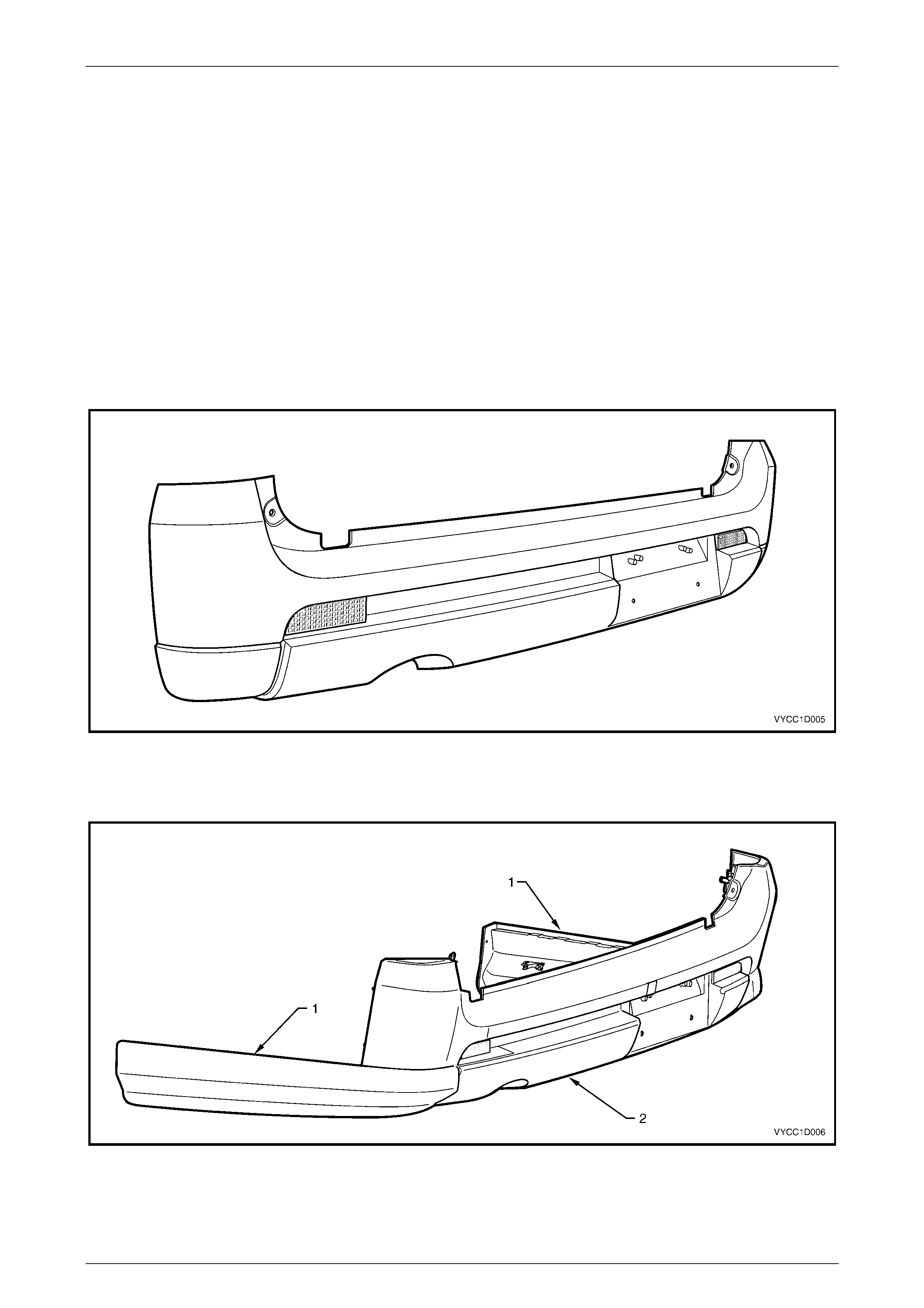
The rear bumper fascia assemblies fitted to Crew Cab vehicles are constructed from polypropylene. Two unique rear
bumper fascia assemblies are fitted to Crew Cab vehicles.
Base and S models are fitted with a full width rear bumper fascia assembly incorporating reflex reflectors and rear
number plate attachment, refer to Figure 1D – 1.
Figure 1D – 1
The rear bumper fascia assembly fitted to SS Crew Cab vehicles incorporates the rear body rear rocker moulding (1),
which is permanently heat staked to the rear bumper fascia assembly (2), refer to Figure 1D – 2.
Figure 1D – 2
Bumper Ba r s Page 1D–3
Page 1D–3
2 Service Operations
2.1 Paint Systems
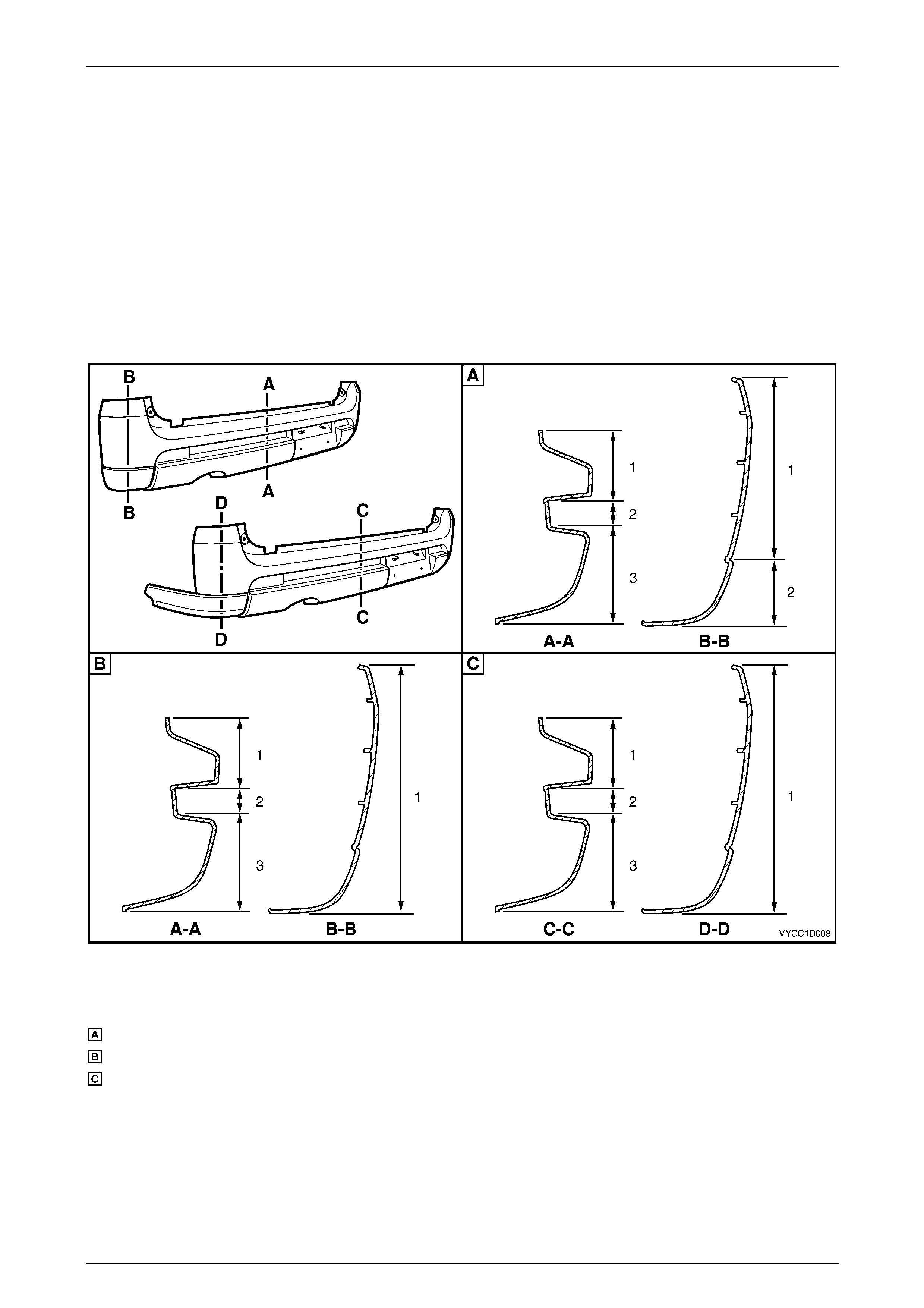
Paint Ma s king
The following illustration shows the rear bumper fascia assembly masking areas for each vehicle model and is provided
to assist when painting a rear bumper fascia assembly to match the factory finish.
For information to refinish the rear bumper fascia assembly, refer to Section 1D Bumper Bars in the MY 2004 VY and V2
Series Service Information.
For further information on the specific model levels, refer to Section 0A General Information.
Figure 1D – 3
Legend
Base Model
S Model
SS Model
1 Body Colour
2 Unpainted
3 Skirt Black
Bumper Ba r s Page 1D–4
Page 1D–4
2.2 Rear Bumper Fascia Assembly
LT Section – 07-525
Remove
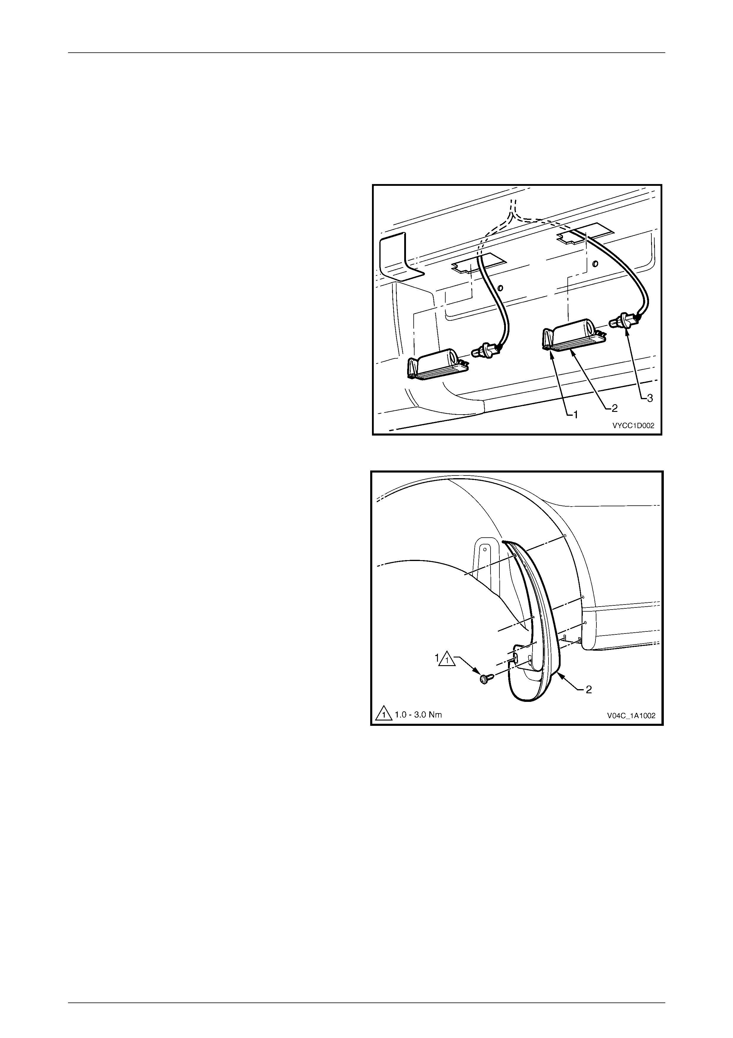
1 Push the locking tang (1) located at the end of the
lamp housing (2) towards the lens. Pivot the lamp
housing down and remove it from the aperture.
2 Remove the bulb socket (3) from the lamp housing
and place the lamp housing in a safe location.
3 Pass the bulb socket through the aperture in the rear
bumper fascia assembly.
4 Repeat Steps 1 to 3 for the other lamp assembly.
Figure 1D – 4
5 For SS vehicles:
a Remove the screw (1), five places attaching the
rear mudflap (2) to the rear body and remove the
mudflap.
Figure 1A1 – 5
Bumper Ba r s Page 1D–5
Page 1D–5
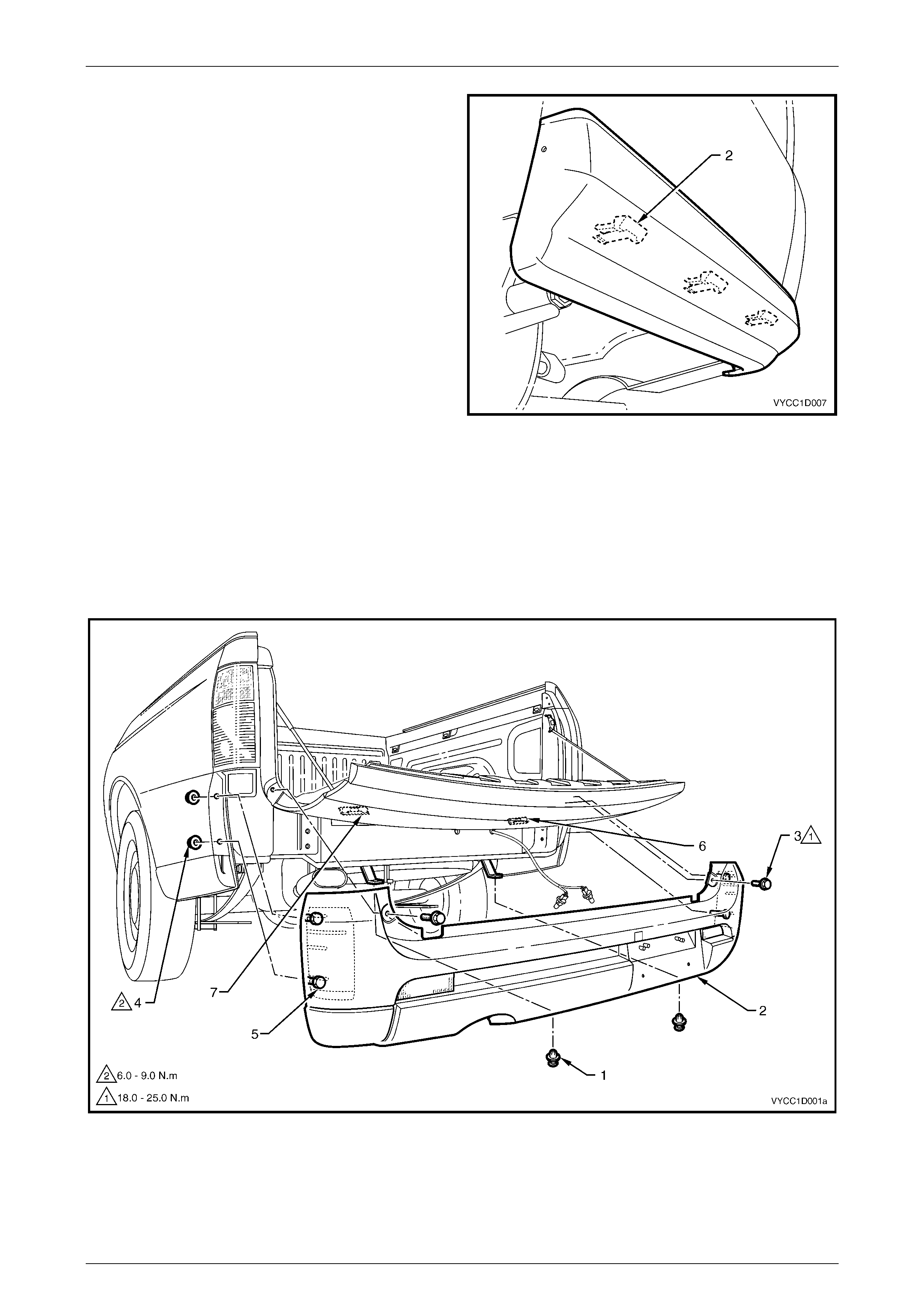
b From behind the rear body panel unclip the
retainers (2), in three places.
c Repeat for the opposite side of the vehicle.
Figure 1D – 6
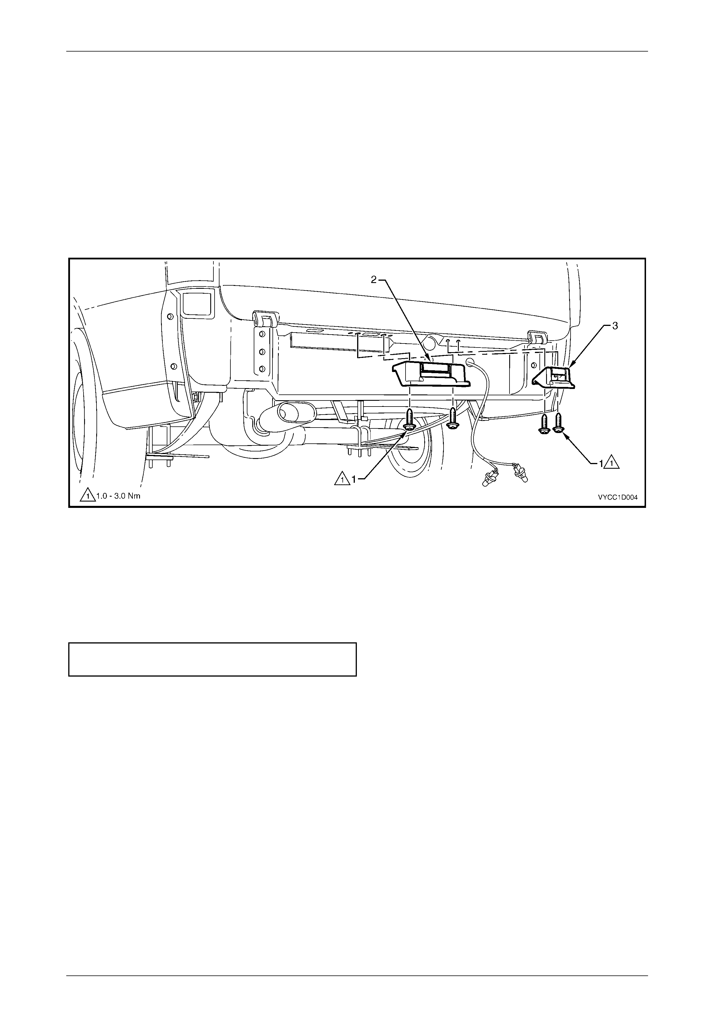
6 Remove the two retainers (1) from beneath the lower edge of the rear bumper fascia assembly (2), refer to Figure
1D – 7.
7 Open the endgate, remove the two screws (3) and close the endgate.
8 Remove the nuts (4) from the studs (5) in two places on each side of the vehicle.
9 Disengage the rear bumper fascia assembly from the rear bumper fascia assembly supports (6) and (7).
10 With the aid of an assistant, remove the rear bumper fascia assembly from the vehicle.
Figure 1D – 7
Bumper Ba r s Page 1D–6
Page 1D–6
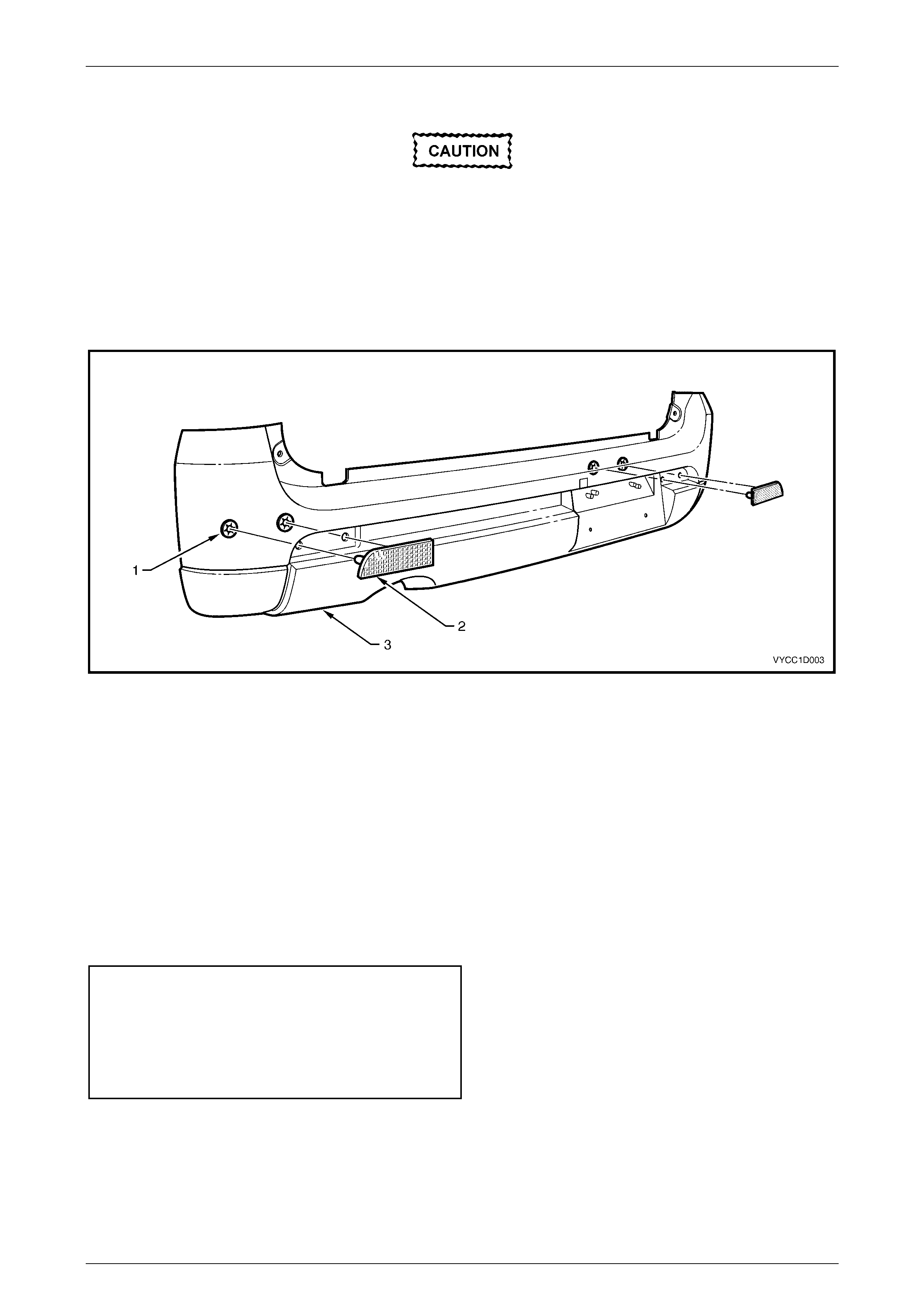
Disassemble
When removing the retainers in Step 1, take care
not to break the shafts on which the retainers are
attached.
1 Remove the two retainers (1) securing the reflex reflector (2) to the rear bumper fascia assembly (3), refer to
Figure 1D – 8.
2 Remove the reflex reflector from the rear bumper fascia.
3 Repeat for the opposite side if required.
Figure 1D – 8
Reassemble
Reassembly of the rear bumper fascia assembly is the reverse of the disassembly procedure.
Reinstall
Reinstallation of the rear bumper fascia assembly is the reverse of the removal procedure, noting the following:
1 If required, refinish the rear bumper fascia assembly, refer to 2.1 Paint Systems.
2 With the aid of an assistant, fit the rear bumper fascia assembly to the vehicle. Ensure that the rear bumper fascia
assembly snaps onto the rear bumper fascia assembly supports.
3 Tighten the fasteners to the specified torque.
Rear bumper fascia assembly attaching
screw torque specification......................18.0 – 25.0 Nm
Rear bumper fascia assembly attaching
nut torque specification .............................. 6.0 – 9.0 Nm
Rear mudflap attaching screw
torque specific atio n .................................... 1.0 – 3.0 Nm
Bumper Ba r s Page 1D–7
Page 1D–7
2.3 Rear Bumper Fascia Support
LT Section – 07-525
Remove
1 As required, remove the rear bumper fascia assembly, refer to 2.2 Rear Bumper Fascia
2 Remove the two screws (1) attaching the rear bumper fascia assembly support and remove the rear bumper fascia
assembly support, refer to Figure 1D – 9.
3 Repeat for the opposite side if required.
Figure 1D – 9
Reinstall
Installation is the reverse of the removal procedure, noting the following:
1 The rear bumper fascia assembly supports (2) and (3) are not interchangeable.
2 Tighten the fasteners to the specified torque.
Rear bumper fascia support assembly
screw torque specification..........................1.0 – 3.0 Nm

Bumper Ba r s Page 1D–8
Page 1D–8
3 Torque Wrench Specifications
Rear Bumper Fascia Assembly Attaching Screw.......................18.0 – 25.0 Nm
Rear Bumper Fascia Assembly Attaching Nut...............................6.0 – 9.0 Nm
Rear Bumper Fascia Assembly Support Screw.............................1.0 – 3.0 Nm
Rear Mudflap Attaching Screw ......................................................1.0 – 3.0 Nm