
Body Control Module Page 12J–1
Page 12J–1
Section 12J
Body Control Module
ATTENTION
Before performing any Service Operation or other procedure described in this Section, refer to Section 00
Warnings, Cautions and Notes for correct workshop practices with regard to safety and / or property damage.
1 General Information............................................................................................................................... 2
1.1 General Description...............................................................................................................................................2
Techline
Techline
Techline
Techline
Techline
Techline
Body Control Module Page 12J–2
Page 12J–2
1 General Information
This section provides information on the Body Control Module (BCM) fitted to the MY 2004 VY Regular and Crew Cab
vehicles.
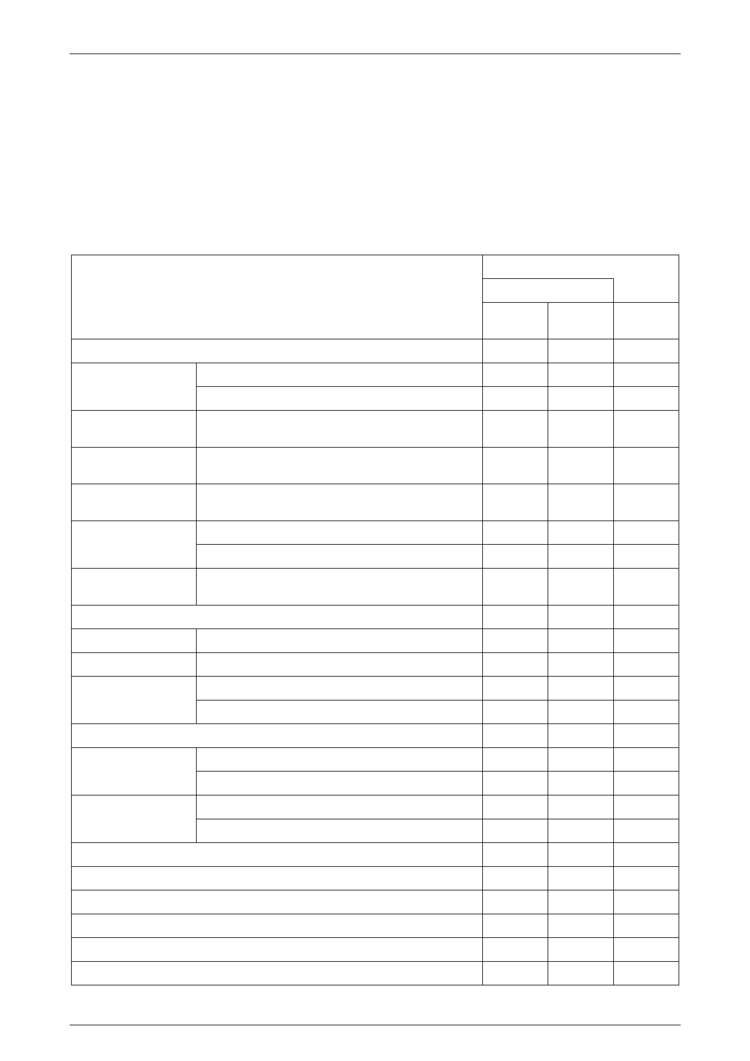
1.1 General Description
The specific BCM features enabled for the MY 2004 VY Regular and Crew Cab vehicles are detailed in the following
table. If a BCM is suspected to be faulty, ensure that the correct BCM as indicated in the table is used as a replacement
item.
Crew Cab
Reg Cab
BCM Features
Base
Model S Model SS Model
BCM Part Number 92155208 92155210 92155209
With deadlocking A A A Central door locki ng
Auto lock in drive User User User
2-Door power window
system With express down on both doors – A –
4-Door power window
system With express down on front doors only. – A A
Approach illuminated
entry At night only User User User
Entry delay and central locking A A A Dome lamp delay
control Ignition OFF courtesy illumination A A A
Intermittent wiper
control With road speed dependent variable dwell A A A
Instrument dimming control A A A
Automatic lights OFF With adjustable delay User User User
Automatic lights ON At twilight User User User
Entry alarm A A A Theft deterrent system
Immobiliser A A A
Engine cooling low speed fan control A A A
Reduce standing current A A A Battery saver
Pre-delivery 3 minute cut-out A A A
Remote central locking with two-stage unlock A A A Remote control via
coded key Remote deadlo ck and und ead l ock w ith stat e feedba ck A A A
Cruise control interface N/A A A
Airbag deploymen t vehi cle shu tdow n A A A
Heated rear window control with delay A A A
Air conditioning system interface (A / C switch) A A A
Multi-function display support A A A
Accessory power control (delayed accessories bus) A A A
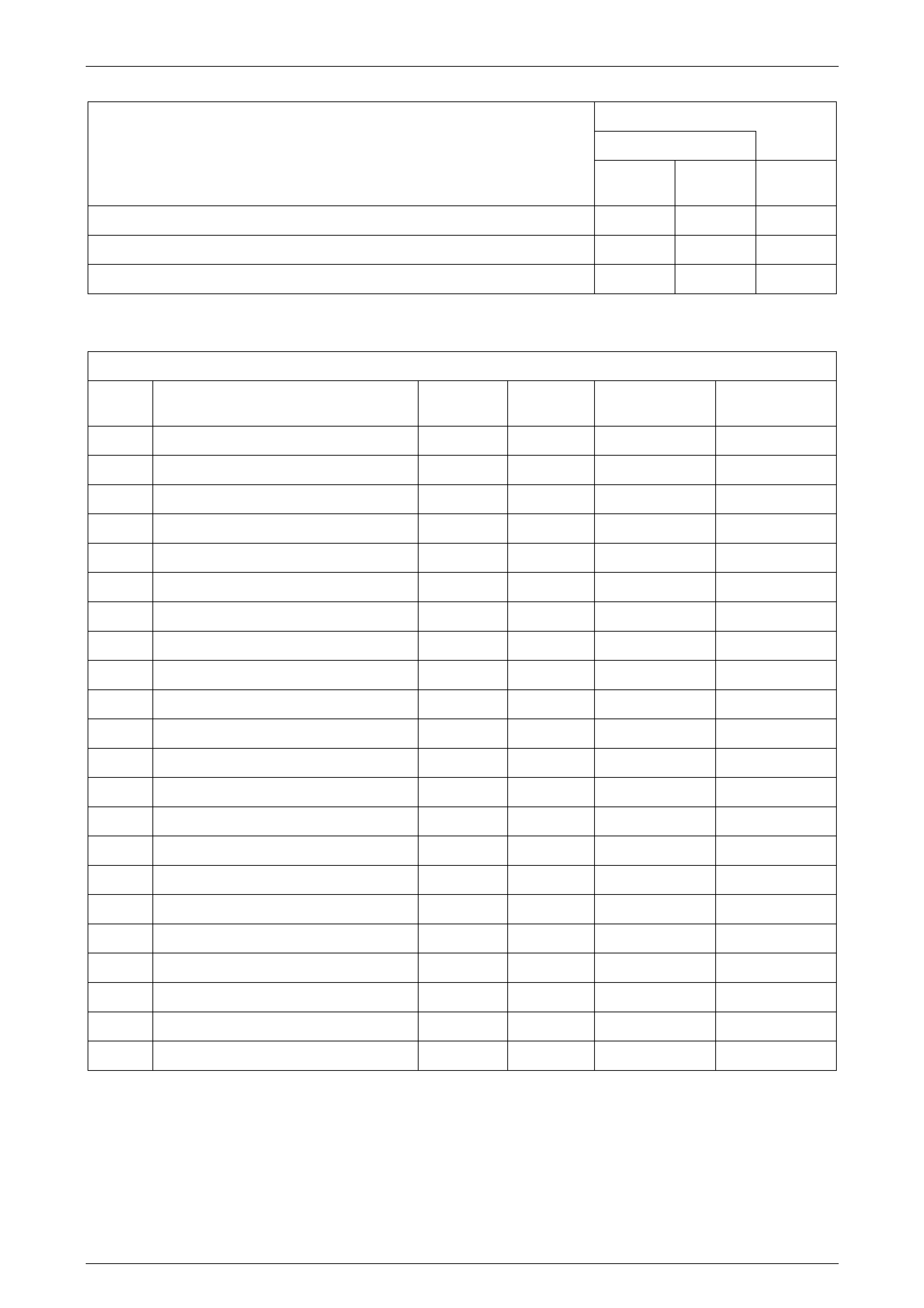
Body Control Module Page 12J–3
Page 12J–3
Crew Cab
Reg Cab
BCM Features
Base
Model S Model SS Model
BCM Part Number 92155208 92155210 92155209
Serial data interface A A A
Daytime running lamps (option) A A A
BCM Terminal Identification
A15 Connector X1
Pin
No. Description Circuit Wire
Colour Active
Signal Circuit
Type
X1–1 Wiper park switch 196 YE Pull to B+ PD/O
X1–2 Intermittent front wiper motor power 243 BN / WH ACC and IGN P
X1–3 Right indicator drive 1315 BU Switch to B+ O
X1–4 Left indicator drive 1314 L-BU Switch to B+ O
X1–5 Instrument illumination drive 230 GY Switch to GND O
X1–6 Auto headlamps on ground 103 WH / RD Switch to GND I
X1–7 – – – – –
X1–8 Power window drive 1351 YE Switch to GND O
X1–9 Accessories relay drive 755 BN / BK Switch to GND O
X1–10 Battery main power 740 OG / BK Always active P
X1–11 Power ground 151 BK / GN Always active GND
X1–12 Wiper drive 96 GN Switch to GND O
X1–13 Turn signal power 140 OG / RD Always active P
X1–14 Receiver ground 219 BN / GN GND GND
X1–15 Low speed fan drive 335 OG / BK Switch to GND O
X1–16 Interior lamps drive 1393 WH Switch to GND O
X1–17 Horn drive 28 BK / YE Switch to GND O
X1–18 Demist drive 681 BK / RD Switch to GND O
X1–19 Air conditioner LED 762 RD / BK Switch to GND O
X1–20 Electronic ground 251 BK / YE Always active GND
X1–21 Security status telltale LED 264 L-BU Switch to GND O
X1–22 Door-lock power 440 OG / PU Always active P
Body Control Module Page 12J–4
Page 12J–4
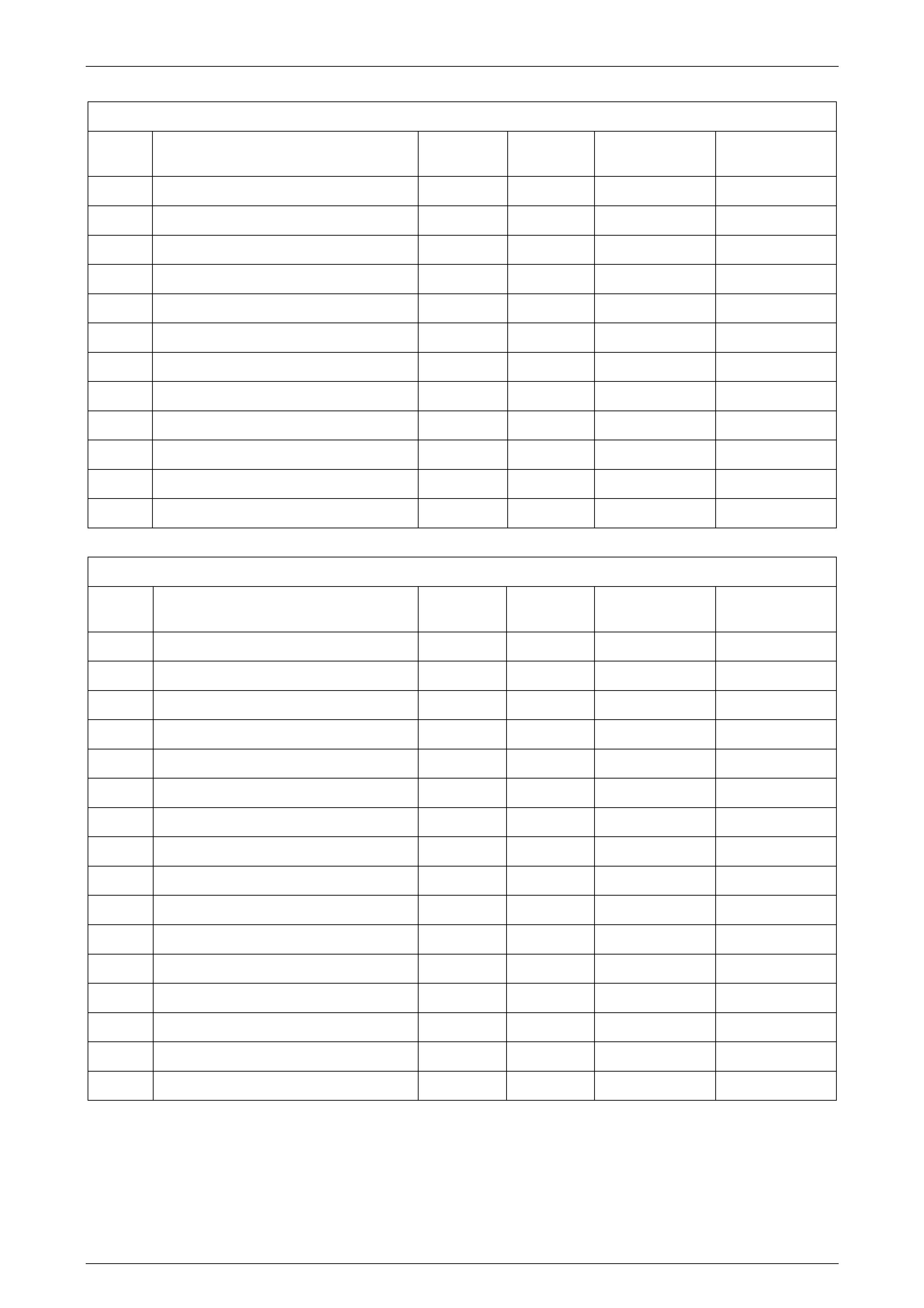
A15 Connector X2
Pin
No. Description Circuit Wire
Colour Active
Signal Circuit
Type
X2–1 Receiver data 218 YE COMMS I
X2–2 Twilight sensor input 1784 YE / BK 0–5 V I/O
X2–3 Instrument dim setting 44 WH 0–5 V PU
X2–4 – – – – –
X2–5 Primary serial data bus 800 RD / BK COMMS I/O
X2–6 Tertiary serial data bus 774 WH / GN COMMS I/O
X2–7 Key reader 1073 PU / RD COMMS I/O
X2–8 – – – – –
X2–9 Secondary serial data bus 1061 GN / WH COMMS I/O
X2–10 Auto headlamps off ground 306 BK Switch to GND PD/O
X2–11 Bonnet pull up 109 RD / WH RES to B+ PPU
X2–12 Demist switch 292 OG Pull to B+ I
A15 Connector X3
Pin No. Description Circuit Wire
Colour Act ive
Signal Circuit
Type
X3–1 Battery – 150 BK Always GND GND
X3–2 Ignition input 300 OG Pull to B+ PD,P
X3–3 Intermittent wiper switch position 112 BU / WH Pull to B+ PPD
X3–4 Accessories on 4 BN / WH Pull to B+ PD,P
X3–5 A / C S w it ch 66 RD / WH Pull to B+ PPD
X3–6 – – – – –
X3–7 – – – – –
X3–8 – – – – –
X3–9 Air conditioner blower switch 63 D-GN / YE Pull to GND PPU
X3–10 – – – – –
X3–11 Hood open 263 YE / BK Pull to GND PPU
X3–12 – – – – –
X3–13 Washer / wiper 228 L-BU Pull to B+ PPD
X3–14 – – – – –
X3–15 Theft horn drive 1149 GN Switch to B+ O
X3–16 Hazard lamps 111 BN Pull to GND PPU
Body Control Module Page 12J–5
Page 12J–5
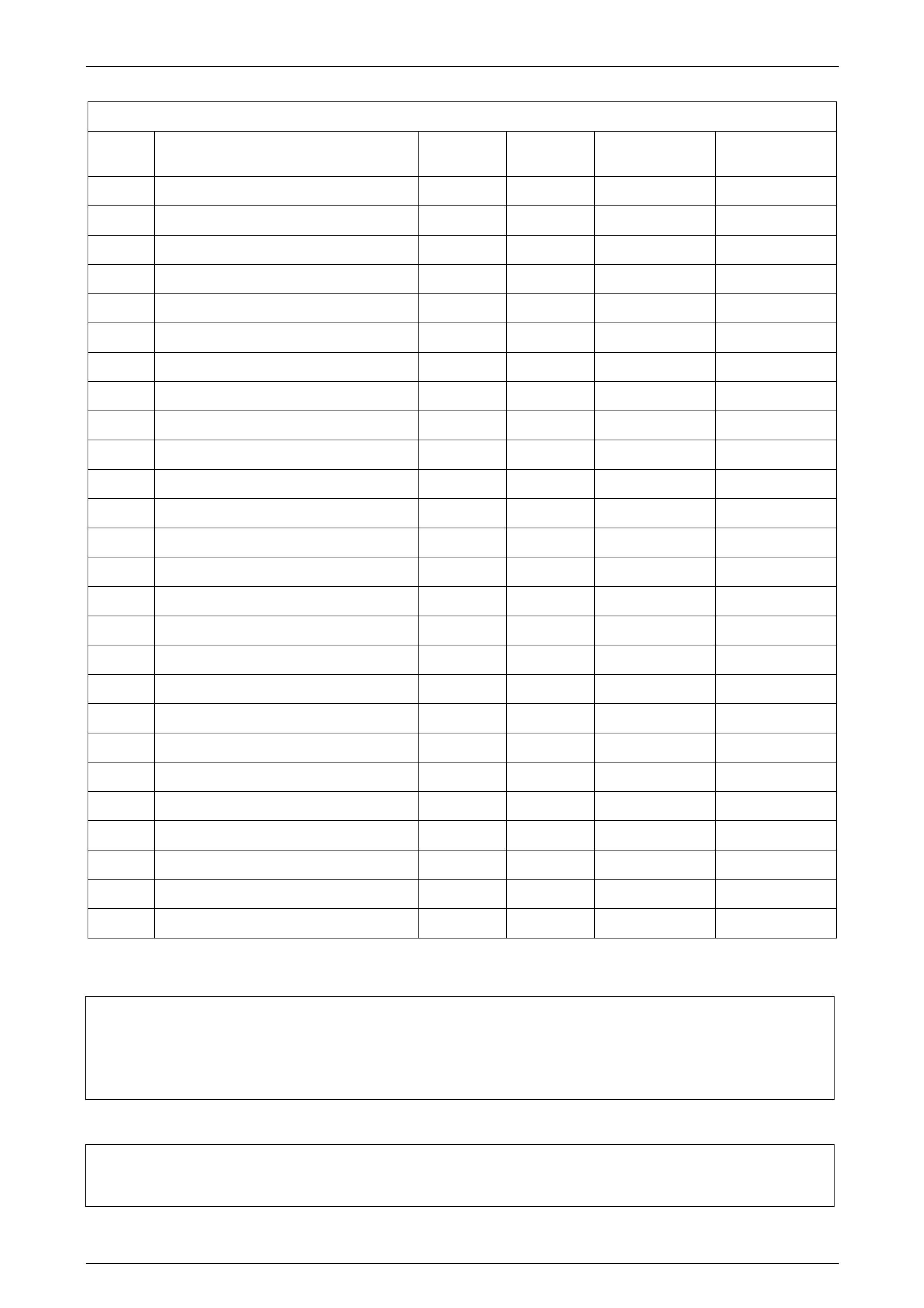
A15 Connector X4
Pin No. Description Circuit Wire
Colour Act ive
Signal Circuit
Type
X4–1 Passenger door unlock drive 294 BK / RD Switch to B+ PPU
X4–2 – – – – –
X4–3 – – – – –
X4–4 Passenger ’s door ajar 745 WH Pull to GND PPU
X4–5 Passenger door unlock request 194 BN / OG Pull to GND PPU
X4–6 – – – – –
X4–7 – – – – –
X4–8 Driver’s door unlock drive 694 BU / BK Switch to B+ O
X4–9 Deadlock drive 5171 PU / WH Switch to B+ O
X4–10 Door-lock drive 295 BK / YE Switch to B+ O
X4–11 Passenger window power source 638 OG / YE Active via relay P
X4–12 Driver window down request 167 GN / BK Pull to B+ PPD
X4–13 Driver window motor 667 GN / OG Switch to B+ O
X4–14 Driver window up request 666 BU / WH Pull to B+ PPD
X4–15 Passenger window up request 164 GN Pull to B+ PPD
X4–16 Driver’s door unlock request 781 L-GN / YE Pull to GND PPU
X4–17 Lock and deadlock request 780 BN / WH Pull to B+ PPU
X4–18 – – – – –
X4–19 Driver’s door ajar 746 GY / WH Pull to GND PPU
X4–20 Lock request 195 BN / RD Pull to GND PPU
X4–21 – – – – –
X4–22 Dome light drive 660 WH / GN Switch to GND O
X4–23 – – – – –
X4–24 – – – – –
X4–25 Passenger side window motor 165 YE Switch to B+ O
X4–26 Passenger window down request 1136 BU Pull to B+ PPD
Legend – Wire Colour
Legend – Circuit Type
GND Earth PD Pull Down PU Pull Up
O Output I Input P P U Pulsed Pull Up
P Power I/O Input / Output
For further information, refer to Section 12J Body Control Module in the MY 2004 VY and V2 Series Service Information.
BK Black GY Grey PU Purple
BN Brown L-BU Light-blue RD Red
BU Blue L-GN Light-green TN Tan
D-GN Dark-green OG Orange WH White
GN Green PK Pink YE Yellow